US20030191925A1 - Technique for reduced-tag dynamic scheduling - Google Patents
Technique for reduced-tag dynamic scheduling Download PDFInfo
- Publication number
- US20030191925A1 US20030191925A1 US10/406,475 US40647503A US2003191925A1 US 20030191925 A1 US20030191925 A1 US 20030191925A1 US 40647503 A US40647503 A US 40647503A US 2003191925 A1 US2003191925 A1 US 2003191925A1
- Authority
- US
- United States
- Prior art keywords
- tag
- operand
- instruction
- subset
- stations
- Prior art date
- Legal status (The legal status is an assumption and is not a legal conclusion. Google has not performed a legal analysis and makes no representation as to the accuracy of the status listed.)
- Granted
Links
- 238000000034 method Methods 0.000 title claims description 12
- 101100534231 Xenopus laevis src-b gene Proteins 0.000 description 8
- 101100496858 Mus musculus Colec12 gene Proteins 0.000 description 5
- 230000001419 dependent effect Effects 0.000 description 2
- 230000015654 memory Effects 0.000 description 2
- 101100534223 Caenorhabditis elegans src-1 gene Proteins 0.000 description 1
- 101100534229 Caenorhabditis elegans src-2 gene Proteins 0.000 description 1
- 230000003111 delayed effect Effects 0.000 description 1
- 230000003467 diminishing effect Effects 0.000 description 1
- 230000008030 elimination Effects 0.000 description 1
- 238000003379 elimination reaction Methods 0.000 description 1
- 238000010348 incorporation Methods 0.000 description 1
- 238000011084 recovery Methods 0.000 description 1
- 230000001373 regressive effect Effects 0.000 description 1
- 239000000523 sample Substances 0.000 description 1
- 238000009738 saturating Methods 0.000 description 1
- 238000010200 validation analysis Methods 0.000 description 1
Images


Classifications
-
- G—PHYSICS
- G06—COMPUTING; CALCULATING OR COUNTING
- G06F—ELECTRIC DIGITAL DATA PROCESSING
- G06F9/00—Arrangements for program control, e.g. control units
- G06F9/06—Arrangements for program control, e.g. control units using stored programs, i.e. using an internal store of processing equipment to receive or retain programs
- G06F9/30—Arrangements for executing machine instructions, e.g. instruction decode
- G06F9/38—Concurrent instruction execution, e.g. pipeline, look ahead
- G06F9/3836—Instruction issuing, e.g. dynamic instruction scheduling or out of order instruction execution
-
- G—PHYSICS
- G06—COMPUTING; CALCULATING OR COUNTING
- G06F—ELECTRIC DIGITAL DATA PROCESSING
- G06F9/00—Arrangements for program control, e.g. control units
- G06F9/06—Arrangements for program control, e.g. control units using stored programs, i.e. using an internal store of processing equipment to receive or retain programs
- G06F9/30—Arrangements for executing machine instructions, e.g. instruction decode
- G06F9/38—Concurrent instruction execution, e.g. pipeline, look ahead
- G06F9/3824—Operand accessing
-
- G—PHYSICS
- G06—COMPUTING; CALCULATING OR COUNTING
- G06F—ELECTRIC DIGITAL DATA PROCESSING
- G06F9/00—Arrangements for program control, e.g. control units
- G06F9/06—Arrangements for program control, e.g. control units using stored programs, i.e. using an internal store of processing equipment to receive or retain programs
- G06F9/30—Arrangements for executing machine instructions, e.g. instruction decode
- G06F9/38—Concurrent instruction execution, e.g. pipeline, look ahead
- G06F9/3836—Instruction issuing, e.g. dynamic instruction scheduling or out of order instruction execution
- G06F9/3842—Speculative instruction execution
- G06F9/3844—Speculative instruction execution using dynamic branch prediction, e.g. using branch history tables
-
- G—PHYSICS
- G06—COMPUTING; CALCULATING OR COUNTING
- G06F—ELECTRIC DIGITAL DATA PROCESSING
- G06F9/00—Arrangements for program control, e.g. control units
- G06F9/06—Arrangements for program control, e.g. control units using stored programs, i.e. using an internal store of processing equipment to receive or retain programs
- G06F9/30—Arrangements for executing machine instructions, e.g. instruction decode
- G06F9/38—Concurrent instruction execution, e.g. pipeline, look ahead
- G06F9/3867—Concurrent instruction execution, e.g. pipeline, look ahead using instruction pipelines
- G06F9/3875—Pipelining a single stage, e.g. superpipelining
Definitions
- the present invention generally relates to a dynamic scheduling technique, and more particularly, the present invention relates to a dynamic scheduling technique that uses tag elimination to improve the performance of dynamic scheduling.
- microprocessor designs In an effort to secure higher levels of system performance, microprocessor designs often employ dynamic scheduling as a technique to extract information level parallelism (ILP) from serial instruction streams.
- ILP information level parallelism
- Conventional dynamic scheduler designs house a window of candidate instructions from which ready instructions are sent to functional units in an out-of-order data flow fashion.
- the instruction window is implemented using large monolithic content addressable memories (CAMs) that track instructions and their input dependencies. While more ILP can be extracted with larger instruction windows (and accordingly larger CAM structures), such an increase in parallelism comes at the expense of slower scheduler clock speed.
- CAMs monolithic content addressable memories
- the present invention provides a dynamic scheduling scheme that uses reservation stations having at least one station that stores an at least two operand instruction.
- An allocator portion determines that the instruction, entering the pipeline, has one ready operand and one not-ready operand, and accordingly places it in a station having only one comparator.
- the one comparator compares the not-ready operand with tags broadcasted on a result tag bus to determine when the not-ready operand becomes ready. Once ready, execution is requested to the corresponding functional unit.
- the last received operand of the two operand instruction is predicted.
- the instruction is then scheduled for execution based on the prediction.
- FIG. 1 is a schematic view of a dynamic scheduler pipeline according to one aspect of the present invention
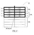
- FIG. 2 is a schematic view of a reservation station according to one aspect of the present invention.
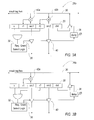
- FIG. 3A is a schematic view of an instruction in a reservation station according to the present invention.
- FIG. 3B is a schematic view of an instruction in a reservation station according to an aspect of the present invention.
- FIG. 4 is a schematic view of a dynamic scheduler pipeline according to an aspect of the present invention.
- FIG. 5 is a schematic view of a last tag predictor according to an aspect of the present invention.
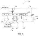
- FIG. 6 is a schematic view of an instruction in a reservation station according to an aspect of the present invention.
- the present invention is based on most tag scheduler comparisons being superfluous to correct operation of the instruction scheduler. Specifically, most instructions placed into the instruction window do not require two source tag comparators due to one or more operands being ready, or because the operation doesn't require two register operands.
- the dynamic scheduler pipeline 10 generally includes an allocator 12 , scheduler stage 14 , register read stage 16 and execution stage 18 . Instruction 20 is passed from stage to stage to ultimately result in its execution as described below.
- the allocator 12 is responsible for reserving all resources necessary to house an instruction in the processor instruction window. These resources include reservation stations 24 , reorder buffer entries, and physical registers.
- Scheduler stage 14 houses instructions in reservation stations 24 until they are ready to execute. Reservation stations 24 track the availability of instruction source operands. When all input operands are available, a request is made to the select logic 32 for execution (as will be described in greater detail).
- the select logic 32 chooses the next instructions 20 to execute from all ready instructions, based on the scheduler policy of scheduler stage 14 .
- the selected instructions 20 receive a grant signal from the selection logic 32 , at which point they are sent to later stages of the pipeline 10 .
- source register tags of an instruction 20 are used to access the register file in the register read stage 16 of the pipeline 10 .
- Operand values read from the register file of the register read stage 16 are forwarded to the appropriate functional unit in the execution stage 18 of the pipeline 10 . If a dependent operation immediately follows an instruction, it will read a stale value from the physical register file.
- a bypass multiplexer is provided in the execution stage 18 to select between the incoming register operand, or a more recent value on the by-pass bus.
- Dependent instructions that execute in subsequent cycles must communicate via the by-pass bus. All other instructions preferably communicate by way of the physical register file.
- a reservation station 24 contains two tag comparator entires 26 A, one tag comparator entries 26 B and zero tag comparator entries 26 C.
- tag comparator entries 26 B and 26 C the reservations station 24 according to the present invention eliminates the need for extra tag comparisons. Specifically, when allocator 12 encounters an instruction 20 with one or more unavailable operands, the allocator assigns the instruction 20 to a reservation station having a matching number of tag comparators. For example, if instruction 20 enters the reservation station 24 without any operands ready, then the instruction is placed into one of the reservation stations 26 A.
- the instructions 20 enters the reservation station having one ready operand, then the instructions 20 is placed into one of the reservation stations 26 B. If all operands are ready, then the instruction 20 is placed into one of the reservation stations 26 C. If a reservation station with a sufficient number of tag comparators is not available, due to more instructions than available reservation stations, then allocator 12 stalls the front end pipeline until a reservation station is available. As a result of the scheme of FIG. 2, unnecessary tag comparisons on instructions are eliminated.
- FIGS. 3A and 3B further describe the data paths and control logic for reservation stations 26 A, having no operands ready, and 26 B, having one operand ready.
- instruction 20 is positioned in one of the available reservation stations 26 A by the allocator 12 .
- the allocator 12 determines that neither operand SRC 1 nor SRC 2 are ready, and therefore places the instruction 20 in one of these reservation stations.
- ready bits R 1 and R 2 are set invalid until the operand is ready.
- the tag comparators 42 a and 42 b compare tags of the operands src 1 and src 2 with tags broadcasted on the result tag bus 30 .
- the select logic 32 grants the execution quest if the appropriate functional unit is available and a requesting instruction 20 has the highest priority among instructions that are ready to execute. If so, the select logic 32 sends the instruction 20 to execution by driving its grant signal.
- the input operand tags src 1 and src 2 are driven onto an output bus where they are latched for use by the register read stage 16 in the following cycle.
- the grant signal 36 is latched at the reservation station 26 A.
- the instruction 20 drives its result tag onto the result tag bus 30 . If the execution pipeline supports multicycle operations, the result tag broadcast must be delayed by a delay element 38 until the instruction result is produced.
- This select logic 32 forms the control critical path in the dynamically scheduled pipeline 10 .
- this logic forms a critical speed path in most regressive designs because it limits the rate at which instructions can begin execution.
- This critical path includes the result tag driver 40 , the result tag bus 30 interconnect, reservation station comparators 42 A and 42 B, the select logic 32 and the grant signal 36 interconnect.
- FIG. 3B illustrates reservations stations 26 B which are dedicated for instructions 20 having one ready operand when they enter the reservation station. Therefore, they do not need to have both tag comparators to compare both tags to the result tag bus 30 as did instructions 20 in FIG. 3A. Accordingly, reservation stations 26 B include only one tag comparator 42 A.
- allocator 12 identifies that operand src 2 , in this particular example, is ready. Therefore, the R 2 bit is set as ready when the allocator places the instruction in the scheduler stage 14 and the operand src 1 is positioned to allow the tag comparator 42 A to snoop the result tag bus and determine when src 1 is ready.
- the tag comparator 42 A compares only the value src 1 with the tags broadcasted on the result tag bus 32 to determine when src 1 is ready. Once the tag comparator 42 A determines that the value src 1 is ready, the ready bit R 1 is set. Then, the execution is requested for the ready instruction 20 . When the instruction is granted permission to execute, the source operand register tags are again driven out to the register stage of the pipeline 10 . With regard to remaining reservation stations 26 C, the instructions having ready values for both src 1 and src 2 are loaded into these reservations stations by the allocator 12 , which contains no tag comparators. As such, these instructions immediately request execution upon entry into the reservation station, and await permission to execute.
- the allocator 12 assigns instructions to a reservation station 24 having a matching number of tag comparators. If both operands src 1 and src 2 are ready, the instruction 20 is placed into the reservation station 26 C without tag comparators and immediately request execution. If there are no available reservation stations having a matching number of tag comparators, the allocator 12 assigns the instruction through reservation stations with more tag comparators. For example, instructions 20 waiting for one operand can be assigned to reservation stations 26 A or 26 B with one or two tag comparators. Of course, if a reservation station with a sufficient number of tag comparators is not available, the allocator will stall the front end pipeline 10 until one becomes available. It should be noted that the scheme depicted in FIG.
- the reservation station 24 includes two entries for two tag comparisons, four entries for one tag comparisons (each block counts as one tag comparison), and the remaining entries for ready instructions.
- FIGS. 4, 5 and 6 another embodiment of the present invention is shown and described.
- the embodiments of FIGS. 4 - 6 include a process for reducing the tag reservation stations by use of a last tag predictor.
- the reservation station is partitioned into stations having one tag comparator.
- allocator 12 accesses the last tag predictor 52 upon receiving instructions 20 with multiple available operands and inserts the instruction 20 into a reservation station 24 with a single tag comparator 50 (see FIG. 6).
- the last tag predictor 52 predicts which operand srcL or srcF, will be available last. If the prediction is correct, the instruction wakes up at the same time it would have in a window without speculation.
- the last tag predictor 52 is indexed with the PC of an instruction 20 (with multiple unavailable operands) hashed with global control history.
- the control history is XOR'ed at 227 with the least significant bits of the instruction PC and that result is used as an index into a table 229 of two-bit saturating counters.
- the value of the upper counter bit indicates the prediction: one indicates the left operand will arrive last, zero indicates the right operand will arrive last.
- the predictors are updated when last tag predictions are validated. If the prediction is incorrect, the instruction wakes up before all operands are ready, and a mis-speculation recovery sequence is initiated.
- the operation of the last tag predictor is described in greater detail.
- the input operand tags are loaded into the reservation station with the operand predicted to be available last is placed under the comparator 50 .
- the operand predicted to be available last is the srcL value.
- the other input operand tag srcF and the result tag are also loaded into the reservation station 24 A.
- the drive operation which drives the operand register tags srcL and srcF out onto the register read stage 16 of the pipeline 10 must be driven through the multiplexers 56 to sort the source operands srcL and srcF into the original instruction order, which is the format used by the register file and later functional units.
- the tag predicted to arrive first is forwarded to the register read stage 16 , where it is used to check the correctness of the last tag prediction.
- the last tag prediction is validated to ensure that the instruction does not commence execution before all of its operands srcL and srcF are available.
- a prediction is validated if the operand predicted to arrive first (srcF) is available when the instruction enters the register read stage 16 of the pipeline 10 .
- the srcF tag is used to probe a small register scoreboard or RDY 58 .
- RDY 58 contains one bit per physical register, where bits are set if the register value is valid in the physical register file.
- RDY 18 is available in the allocator 12 stage of the pipeline 10 where it is used to determine if the valid bit should be set when operand tags are written into reservation stations 24 . A number of ports equal to the issue with RDY 18 will suffice for validating last tag predictions. Alternatively, an additional RDY 18 can be maintained specifically for last tag prediction validation.
- the instruction 20 continues through the scheduler pipeline 10 as the scheduler has made the correct scheduling decision. If the prediction is incorrect, the scheduler pipeline is flushed and restarted, in a fashion identical to latency mispredictions. Unlike latency mispredictions, however, which are detected in memory with a three cycle penalty, last tag mispredictions can be detected before the execution stage 18 , and thus only cause one cycle to bubble in the scheduler pipeline 10 .
Abstract
Description
- This application claims priority based on U.S. Provisional Patent Application No. 60/370,027 filed Apr. 4, 2002, the entirety of which is incorporated herein by reference.
- The present invention generally relates to a dynamic scheduling technique, and more particularly, the present invention relates to a dynamic scheduling technique that uses tag elimination to improve the performance of dynamic scheduling.
- In an effort to secure higher levels of system performance, microprocessor designs often employ dynamic scheduling as a technique to extract information level parallelism (ILP) from serial instruction streams. Conventional dynamic scheduler designs house a window of candidate instructions from which ready instructions are sent to functional units in an out-of-order data flow fashion. The instruction window is implemented using large monolithic content addressable memories (CAMs) that track instructions and their input dependencies. While more ILP can be extracted with larger instruction windows (and accordingly larger CAM structures), such an increase in parallelism comes at the expense of slower scheduler clock speed.
- In addition to performance, power dissipation has become an increasing concern in the design of high performance microprocessors. Increasing clock speeds and diminishing voltage margins have combined to produce designs that are increasingly difficult to cool. Additionally, embedded processors are more sensitive to energy usage as these designs are often powered by batteries. The present invention was developed in light of these and other obstacles.
- To address these and other drawbacks, the present invention provides a dynamic scheduling scheme that uses reservation stations having at least one station that stores an at least two operand instruction. An allocator portion determines that the instruction, entering the pipeline, has one ready operand and one not-ready operand, and accordingly places it in a station having only one comparator. The one comparator then compares the not-ready operand with tags broadcasted on a result tag bus to determine when the not-ready operand becomes ready. Once ready, execution is requested to the corresponding functional unit.
- In another aspect of the invention, the last received operand of the two operand instruction is predicted. The instruction is then scheduled for execution based on the prediction.
- Other aspects o f the invention will be apparent to those skilled in the art after reviewing the drawings and the detailed description below.
- The present invention will now be described, by way of example, with reference to the accompanying drawings, in which:
- FIG. 1 is a schematic view of a dynamic scheduler pipeline according to one aspect of the present invention;
- FIG. 2 is a schematic view of a reservation station according to one aspect of the present invention;
- FIG. 3A is a schematic view of an instruction in a reservation station according to the present invention;
- FIG. 3B is a schematic view of an instruction in a reservation station according to an aspect of the present invention;
- FIG. 4 is a schematic view of a dynamic scheduler pipeline according to an aspect of the present invention;
- FIG. 5 is a schematic view of a last tag predictor according to an aspect of the present invention;
- FIG. 6 is a schematic view of an instruction in a reservation station according to an aspect of the present invention.
- It is to be understood that the present invention may be embodied in other specific forms without departing from its essential characteristics. The illustrated and described embodiments are to be considered in all respects only as illustrative and not restrictive. The scope of the invention is, therefore, indicated by the appended claims rather than by the foregoing description. All changes that come within the meaning and range of equivalency of the claims are to be embraced within their scope.
- The present invention is based on most tag scheduler comparisons being superfluous to correct operation of the instruction scheduler. Specifically, most instructions placed into the instruction window do not require two source tag comparators due to one or more operands being ready, or because the operation doesn't require two register operands.
- Referring now to FIG. 1, a
dynamic scheduler pipeline 10 according to an aspect of the present invention is shown and described. Thedynamic scheduler pipeline 10 generally includes anallocator 12,scheduler stage 14, register readstage 16 andexecution stage 18.Instruction 20 is passed from stage to stage to ultimately result in its execution as described below. - The
allocator 12 is responsible for reserving all resources necessary to house an instruction in the processor instruction window. These resources includereservation stations 24, reorder buffer entries, and physical registers.Scheduler stage 14 houses instructions inreservation stations 24 until they are ready to execute.Reservation stations 24 track the availability of instruction source operands. When all input operands are available, a request is made to theselect logic 32 for execution (as will be described in greater detail). Theselect logic 32 chooses thenext instructions 20 to execute from all ready instructions, based on the scheduler policy ofscheduler stage 14. The selectedinstructions 20 receive a grant signal from theselection logic 32, at which point they are sent to later stages of thepipeline 10. - Once granted execution, source register tags of an
instruction 20 are used to access the register file in the register readstage 16 of thepipeline 10. Operand values read from the register file of the register readstage 16 are forwarded to the appropriate functional unit in theexecution stage 18 of thepipeline 10. If a dependent operation immediately follows an instruction, it will read a stale value from the physical register file. A bypass multiplexer is provided in theexecution stage 18 to select between the incoming register operand, or a more recent value on the by-pass bus. Dependent instructions that execute in subsequent cycles must communicate via the by-pass bus. All other instructions preferably communicate by way of the physical register file. - Referring now to FIGS. 2, 3A and 3B,
reservations stations 24 according to thedynamic scheduler pipeline 10 are described in greater detail. In FIG. 2, areservation station 24 contains two tag comparator entires 26A, one tag comparator entries 26B and zero tag comparator entries 26C. By defining tag comparator entries 26B and 26C, thereservations station 24 according to the present invention eliminates the need for extra tag comparisons. Specifically, whenallocator 12 encounters aninstruction 20 with one or more unavailable operands, the allocator assigns theinstruction 20 to a reservation station having a matching number of tag comparators. For example, ifinstruction 20 enters thereservation station 24 without any operands ready, then the instruction is placed into one of the reservation stations 26A. Likewise, if theinstruction 20 enters the reservation station having one ready operand, then theinstructions 20 is placed into one of the reservation stations 26B. If all operands are ready, then theinstruction 20 is placed into one of the reservation stations 26C. If a reservation station with a sufficient number of tag comparators is not available, due to more instructions than available reservation stations, thenallocator 12 stalls the front end pipeline until a reservation station is available. As a result of the scheme of FIG. 2, unnecessary tag comparisons on instructions are eliminated. - FIGS. 3A and 3B further describe the data paths and control logic for reservation stations 26A, having no operands ready, and 26B, having one operand ready. In FIG. 3A,
instruction 20 is positioned in one of the available reservation stations 26A by theallocator 12. Theallocator 12 determines that neitheroperand SRC 1 nor SRC 2 are ready, and therefore places theinstruction 20 in one of these reservation stations. Here, ready bits R1 and R2 are set invalid until the operand is ready. To ascertain when either operand src1 or src2 is ready, thetag comparators result tag bus 30. Specifically, when general instructions are nearing the completion of their execution, they broadcast their result tag onto theresult tag bus 30. The reservation stations 26A thus snoop theresult tag bus 30, via thetag comparators select logic 32. Theselect logic 32 grants the execution quest if the appropriate functional unit is available and a requestinginstruction 20 has the highest priority among instructions that are ready to execute. If so, theselect logic 32 sends theinstruction 20 to execution by driving its grant signal. The input operand tags src1 and src2 are driven onto an output bus where they are latched for use by the register readstage 16 in the following cycle. In addition, thegrant signal 36 is latched at the reservation station 26A. In the subsequent cycle, theinstruction 20 drives its result tag onto theresult tag bus 30. If the execution pipeline supports multicycle operations, the result tag broadcast must be delayed by adelay element 38 until the instruction result is produced. - This
select logic 32 forms the control critical path in the dynamically scheduledpipeline 10. Thus, this logic forms a critical speed path in most regressive designs because it limits the rate at which instructions can begin execution. This critical path includes theresult tag driver 40, theresult tag bus 30 interconnect, reservation station comparators 42A and 42B, theselect logic 32 and thegrant signal 36 interconnect. - FIG. 3B illustrates reservations stations 26B which are dedicated for
instructions 20 having one ready operand when they enter the reservation station. Therefore, they do not need to have both tag comparators to compare both tags to theresult tag bus 30 as didinstructions 20 in FIG. 3A. Accordingly, reservation stations 26B include only one tag comparator 42A. In this example,allocator 12 identifies that operand src2, in this particular example, is ready. Therefore, the R2 bit is set as ready when the allocator places the instruction in thescheduler stage 14 and the operand src1 is positioned to allow the tag comparator 42A to snoop the result tag bus and determine when src1 is ready. The tag comparator 42A compares only the value src1 with the tags broadcasted on theresult tag bus 32 to determine when src1 is ready. Once the tag comparator 42A determines that the value src1 is ready, the ready bit R1 is set. Then, the execution is requested for theready instruction 20. When the instruction is granted permission to execute, the source operand register tags are again driven out to the register stage of thepipeline 10. With regard to remaining reservation stations 26C, the instructions having ready values for both src1 and src2 are loaded into these reservations stations by theallocator 12, which contains no tag comparators. As such, these instructions immediately request execution upon entry into the reservation station, and await permission to execute. - Accordingly, the
allocator 12 assigns instructions to areservation station 24 having a matching number of tag comparators. If both operands src1 and src2 are ready, theinstruction 20 is placed into the reservation station 26C without tag comparators and immediately request execution. If there are no available reservation stations having a matching number of tag comparators, theallocator 12 assigns the instruction through reservation stations with more tag comparators. For example,instructions 20 waiting for one operand can be assigned to reservation stations 26A or 26B with one or two tag comparators. Of course, if a reservation station with a sufficient number of tag comparators is not available, the allocator will stall thefront end pipeline 10 until one becomes available. It should be noted that the scheme depicted in FIG. 2 may be altered to include more or less of any of the reservation station type 26A-26C. In a preferred embodiment of the present invention, thereservation station 24 includes two entries for two tag comparisons, four entries for one tag comparisons (each block counts as one tag comparison), and the remaining entries for ready instructions. - Referring now to FIGS. 4, 5 and 6, another embodiment of the present invention is shown and described. The embodiments of FIGS. 4-6 include a process for reducing the tag reservation stations by use of a last tag predictor. In this embodiment, the reservation station is partitioned into stations having one tag comparator. Here, as shown in FIG. 4,
allocator 12 accesses thelast tag predictor 52 upon receivinginstructions 20 with multiple available operands and inserts theinstruction 20 into areservation station 24 with a single tag comparator 50 (see FIG. 6). Thelast tag predictor 52 predicts which operand srcL or srcF, will be available last. If the prediction is correct, the instruction wakes up at the same time it would have in a window without speculation. As shown in FIG. 5, thelast tag predictor 52 is indexed with the PC of an instruction 20 (with multiple unavailable operands) hashed with global control history. The control history is XOR'ed at 227 with the least significant bits of the instruction PC and that result is used as an index into a table 229 of two-bit saturating counters. The value of the upper counter bit indicates the prediction: one indicates the left operand will arrive last, zero indicates the right operand will arrive last. The predictors are updated when last tag predictions are validated. If the prediction is incorrect, the instruction wakes up before all operands are ready, and a mis-speculation recovery sequence is initiated. - With reference to FIG. 6, the operation of the last tag predictor is described in greater detail. In FIG. 6, the input operand tags are loaded into the reservation station with the operand predicted to be available last is placed under the
comparator 50. In the present example, the operand predicted to be available last is the srcL value. The other input operand tag srcF and the result tag are also loaded into the reservation station 24A. Once the instruction requests execution and execution is granted, the instruction undergoes a similar process as described previously for execution. However, in addition, the drive operation which drives the operand register tags srcL and srcF out onto the register readstage 16 of thepipeline 10 must be driven through themultiplexers 56 to sort the source operands srcL and srcF into the original instruction order, which is the format used by the register file and later functional units. In addition, the tag predicted to arrive first is forwarded to the register readstage 16, where it is used to check the correctness of the last tag prediction. - The last tag prediction is validated to ensure that the instruction does not commence execution before all of its operands srcL and srcF are available. A prediction is validated if the operand predicted to arrive first (srcF) is available when the instruction enters the register read
stage 16 of thepipeline 10. In parallel with the register file access in register readstage 16, the srcF tag is used to probe a small register scoreboard orRDY 58.RDY 58 contains one bit per physical register, where bits are set if the register value is valid in the physical register file.RDY 18 is available in theallocator 12 stage of thepipeline 10 where it is used to determine if the valid bit should be set when operand tags are written intoreservation stations 24. A number of ports equal to the issue withRDY 18 will suffice for validating last tag predictions. Alternatively, anadditional RDY 18 can be maintained specifically for last tag prediction validation. - If the prediction is correct, the
instruction 20 continues through thescheduler pipeline 10 as the scheduler has made the correct scheduling decision. If the prediction is incorrect, the scheduler pipeline is flushed and restarted, in a fashion identical to latency mispredictions. Unlike latency mispredictions, however, which are detected in memory with a three cycle penalty, last tag mispredictions can be detected before theexecution stage 18, and thus only cause one cycle to bubble in thescheduler pipeline 10. - While the present invention has been particularly shown and described with reference to the foregoing preferred and alternative embodiments, it should be understood by those skilled in the art that various alternatives to the embodiments of the invention described herein may be employed in practicing the invention without departing from the spirit and scope of the invention as defined in the following claims. It is intended that the following claims define the scope of the invention and that the method and apparatus within the scope of these claims and their equivalents be covered thereby. This description of the invention should be understood to include all novel and non-obvious combinations of elements described herein, and claims may be presented in this or a later application to any novel and non-obvious combination of these elements. The foregoing embodiments are illustrative, and no single feature or element is essential to all possible combinations that may be claimed in this or a later application. Where the claims recite “a” or “a first” element of the equivalent thereof, such claims should be understood to include incorporation of one or more such elements, neither requiring nor excluding two or more such elements.
Claims (18)
Priority Applications (3)
| Application Number | Priority Date | Filing Date | Title |
|---|---|---|---|
| US10/406,475 US7398375B2 (en) | 2002-04-04 | 2003-04-03 | Technique for reduced-tag dynamic scheduling and reduced-tag prediction |
| AU2003223450A AU2003223450A1 (en) | 2002-04-04 | 2003-04-04 | Technique for reduced-tag dynamic scheduling |
| PCT/US2003/010329 WO2003085515A1 (en) | 2002-04-04 | 2003-04-04 | Technique for reduced-tag dynamic scheduling |
Applications Claiming Priority (2)
| Application Number | Priority Date | Filing Date | Title |
|---|---|---|---|
| US37002702P | 2002-04-04 | 2002-04-04 | |
| US10/406,475 US7398375B2 (en) | 2002-04-04 | 2003-04-03 | Technique for reduced-tag dynamic scheduling and reduced-tag prediction |
Publications (2)
| Publication Number | Publication Date |
|---|---|
| US20030191925A1 true US20030191925A1 (en) | 2003-10-09 |
| US7398375B2 US7398375B2 (en) | 2008-07-08 |
Family
ID=28678305
Family Applications (1)
| Application Number | Title | Priority Date | Filing Date |
|---|---|---|---|
| US10/406,475 Active 2025-03-23 US7398375B2 (en) | 2002-04-04 | 2003-04-03 | Technique for reduced-tag dynamic scheduling and reduced-tag prediction |
Country Status (3)
| Country | Link |
|---|---|
| US (1) | US7398375B2 (en) |
| AU (1) | AU2003223450A1 (en) |
| WO (1) | WO2003085515A1 (en) |
Cited By (6)
| Publication number | Priority date | Publication date | Assignee | Title |
|---|---|---|---|---|
| US20100058035A1 (en) * | 2008-08-28 | 2010-03-04 | International Business Machines Corporation | System and Method for Double-Issue Instructions Using a Dependency Matrix |
| GB2448276B (en) * | 2006-02-28 | 2011-06-15 | Mips Tech Inc | Distributive scoreboard scheduling in an out-of-order processor |
| US8135942B2 (en) | 2008-08-28 | 2012-03-13 | International Business Machines Corpration | System and method for double-issue instructions using a dependency matrix and a side issue queue |
| US9256428B2 (en) | 2013-02-06 | 2016-02-09 | International Business Machines Corporation | Load latency speculation in an out-of-order computer processor |
| WO2021206801A1 (en) * | 2020-04-08 | 2021-10-14 | Microsoft Technology Licensing, Llc | Operand pool instruction reservation clustering in a scheduler circuit in a processor |
| CN114816526A (en) * | 2022-04-19 | 2022-07-29 | 北京微核芯科技有限公司 | Operand domain multiplexing-based multi-operand instruction processing method and device |
Families Citing this family (2)
| Publication number | Priority date | Publication date | Assignee | Title |
|---|---|---|---|---|
| US20070203161A1 (en) | 2006-02-24 | 2007-08-30 | Rigel Pharmaceuticals, Inc. | Compositions and methods for inhibition of the jak pathway |
| US8838544B2 (en) * | 2009-09-23 | 2014-09-16 | International Business Machines Corporation | Fast history based compression in a pipelined architecture |
Citations (13)
| Publication number | Priority date | Publication date | Assignee | Title |
|---|---|---|---|---|
| US5404470A (en) * | 1991-11-26 | 1995-04-04 | Matsushita Electric Industrial Co., Ltd. | Information processing apparatus for processing instructions by out-of-order execution |
| US5473526A (en) * | 1994-04-22 | 1995-12-05 | University Of Southern California | System and method for power-efficient charging and discharging of a capacitive load from a single source |
| US5506520A (en) * | 1995-01-11 | 1996-04-09 | International Business Machines Corporation | Energy conserving clock pulse generating circuits |
| US5517145A (en) * | 1994-10-31 | 1996-05-14 | International Business Machines Corporation | CMOS toggle flip-flop using adiabatic switching |
| US5526319A (en) * | 1995-01-31 | 1996-06-11 | International Business Machines Corporation | Memory with adiabatically switched bit lines |
| US5546597A (en) * | 1994-02-28 | 1996-08-13 | Intel Corporation | Ready selection of data dependent instructions using multi-cycle cams in a processor performing out-of-order instruction execution |
| US5559478A (en) * | 1995-07-17 | 1996-09-24 | University Of Southern California | Highly efficient, complementary, resonant pulse generation |
| US5590352A (en) * | 1994-04-26 | 1996-12-31 | Advanced Micro Devices, Inc. | Dependency checking and forwarding of variable width operands |
| US5604912A (en) * | 1992-12-31 | 1997-02-18 | Seiko Epson Corporation | System and method for assigning tags to instructions to control instruction execution |
| US5634026A (en) * | 1995-05-12 | 1997-05-27 | International Business Machines Corporation | Source identifier for result forwarding |
| US5655096A (en) * | 1990-10-12 | 1997-08-05 | Branigin; Michael H. | Method and apparatus for dynamic scheduling of instructions to ensure sequentially coherent data in a processor employing out-of-order execution |
| US5838203A (en) * | 1996-12-06 | 1998-11-17 | Intel Corporation | Method and apparatus for generating waveforms using adiabatic circuitry |
| US6516405B1 (en) * | 1999-12-30 | 2003-02-04 | Intel Corporation | Method and system for safe data dependency collapsing based on control-flow speculation |
-
2003
- 2003-04-03 US US10/406,475 patent/US7398375B2/en active Active
- 2003-04-04 AU AU2003223450A patent/AU2003223450A1/en not_active Abandoned
- 2003-04-04 WO PCT/US2003/010329 patent/WO2003085515A1/en not_active Application Discontinuation
Patent Citations (14)
| Publication number | Priority date | Publication date | Assignee | Title |
|---|---|---|---|---|
| US5655096A (en) * | 1990-10-12 | 1997-08-05 | Branigin; Michael H. | Method and apparatus for dynamic scheduling of instructions to ensure sequentially coherent data in a processor employing out-of-order execution |
| US5404470A (en) * | 1991-11-26 | 1995-04-04 | Matsushita Electric Industrial Co., Ltd. | Information processing apparatus for processing instructions by out-of-order execution |
| US5604912A (en) * | 1992-12-31 | 1997-02-18 | Seiko Epson Corporation | System and method for assigning tags to instructions to control instruction execution |
| US5546597A (en) * | 1994-02-28 | 1996-08-13 | Intel Corporation | Ready selection of data dependent instructions using multi-cycle cams in a processor performing out-of-order instruction execution |
| US5473526A (en) * | 1994-04-22 | 1995-12-05 | University Of Southern California | System and method for power-efficient charging and discharging of a capacitive load from a single source |
| USRE37552E1 (en) * | 1994-04-22 | 2002-02-19 | University Of Southern California | System and method for power-efficient charging and discharging of a capacitive load from a single source |
| US5590352A (en) * | 1994-04-26 | 1996-12-31 | Advanced Micro Devices, Inc. | Dependency checking and forwarding of variable width operands |
| US5517145A (en) * | 1994-10-31 | 1996-05-14 | International Business Machines Corporation | CMOS toggle flip-flop using adiabatic switching |
| US5506520A (en) * | 1995-01-11 | 1996-04-09 | International Business Machines Corporation | Energy conserving clock pulse generating circuits |
| US5526319A (en) * | 1995-01-31 | 1996-06-11 | International Business Machines Corporation | Memory with adiabatically switched bit lines |
| US5634026A (en) * | 1995-05-12 | 1997-05-27 | International Business Machines Corporation | Source identifier for result forwarding |
| US5559478A (en) * | 1995-07-17 | 1996-09-24 | University Of Southern California | Highly efficient, complementary, resonant pulse generation |
| US5838203A (en) * | 1996-12-06 | 1998-11-17 | Intel Corporation | Method and apparatus for generating waveforms using adiabatic circuitry |
| US6516405B1 (en) * | 1999-12-30 | 2003-02-04 | Intel Corporation | Method and system for safe data dependency collapsing based on control-flow speculation |
Cited By (9)
| Publication number | Priority date | Publication date | Assignee | Title |
|---|---|---|---|---|
| GB2448276B (en) * | 2006-02-28 | 2011-06-15 | Mips Tech Inc | Distributive scoreboard scheduling in an out-of-order processor |
| US20100058035A1 (en) * | 2008-08-28 | 2010-03-04 | International Business Machines Corporation | System and Method for Double-Issue Instructions Using a Dependency Matrix |
| US8135942B2 (en) | 2008-08-28 | 2012-03-13 | International Business Machines Corpration | System and method for double-issue instructions using a dependency matrix and a side issue queue |
| US8239661B2 (en) | 2008-08-28 | 2012-08-07 | International Business Machines Corporation | System and method for double-issue instructions using a dependency matrix |
| US9256428B2 (en) | 2013-02-06 | 2016-02-09 | International Business Machines Corporation | Load latency speculation in an out-of-order computer processor |
| US9262160B2 (en) | 2013-02-06 | 2016-02-16 | International Business Machines Corporation | Load latency speculation in an out-of-order computer processor |
| WO2021206801A1 (en) * | 2020-04-08 | 2021-10-14 | Microsoft Technology Licensing, Llc | Operand pool instruction reservation clustering in a scheduler circuit in a processor |
| US11392410B2 (en) | 2020-04-08 | 2022-07-19 | Microsoft Technology Licensing, Llc | Operand pool instruction reservation clustering in a scheduler circuit in a processor |
| CN114816526A (en) * | 2022-04-19 | 2022-07-29 | 北京微核芯科技有限公司 | Operand domain multiplexing-based multi-operand instruction processing method and device |
Also Published As
| Publication number | Publication date |
|---|---|
| AU2003223450A1 (en) | 2003-10-20 |
| WO2003085515A1 (en) | 2003-10-16 |
| US7398375B2 (en) | 2008-07-08 |
Similar Documents
| Publication | Publication Date | Title |
|---|---|---|
| KR101754462B1 (en) | Method and apparatus for implementing a dynamic out-of-order processor pipeline | |
| US9524164B2 (en) | Specialized memory disambiguation mechanisms for different memory read access types | |
| US7181598B2 (en) | Prediction of load-store dependencies in a processing agent | |
| US7941607B1 (en) | Method and system for promoting traces in an instruction processing circuit | |
| US8166282B2 (en) | Multi-version register file for multithreading processors with live-in precomputation | |
| Kim et al. | Warped-preexecution: A GPU pre-execution approach for improving latency hiding | |
| CN108845830B (en) | Execution method of one-to-one loading instruction | |
| US20120023314A1 (en) | Paired execution scheduling of dependent micro-operations | |
| KR20120070584A (en) | Store aware prefetching for a data stream | |
| CN1945525A (en) | System and method for time-of-life counter design for handling instruction flushes from a queue | |
| US20070101110A1 (en) | Processor core and method for managing branch misprediction in an out-of-order processor pipeline | |
| US7398375B2 (en) | Technique for reduced-tag dynamic scheduling and reduced-tag prediction | |
| US6988185B2 (en) | Select-free dynamic instruction scheduling | |
| US20160011874A1 (en) | Silent memory instructions and miss-rate tracking to optimize switching policy on threads in a processing device | |
| US7949854B1 (en) | Trace unit with a trace builder | |
| US7734901B2 (en) | Processor core and method for managing program counter redirection in an out-of-order processor pipeline | |
| US7966479B1 (en) | Concurrent vs. low power branch prediction | |
| US5784639A (en) | Load buffer integrated dynamic decoding logic | |
| US20190057093A1 (en) | Ranking items | |
| EP3757772A1 (en) | System, apparatus and method for a hybrid reservation station for a processor | |
| US7953933B1 (en) | Instruction cache, decoder circuit, basic block cache circuit and multi-block cache circuit | |
| Iliakis et al. | LOOG: Improving GPU Efficiency With Light-Weight Out-Of-Order Execution | |
| KR100861701B1 (en) | Register renaming system and method based on value similarity | |
| US8015359B1 (en) | Method and system for utilizing a common structure for trace verification and maintaining coherency in an instruction processing circuit | |
| WO2007084202A2 (en) | Processor core and method for managing branch misprediction in an out-of-order processor pipeline |
Legal Events
| Date | Code | Title | Description |
|---|---|---|---|
| AS | Assignment |
Owner name: REGENTS OF THE UNIVERSITY OF MICHIGAN, THE, MICHIG Free format text: ASSIGNMENT OF ASSIGNORS INTEREST;ASSIGNORS:ERNST, DANIEL J.;AUSTIN, TODD M.;REEL/FRAME:013936/0751 Effective date: 20030403 |
|
| STCF | Information on status: patent grant |
Free format text: PATENTED CASE |
|
| FPAY | Fee payment |
Year of fee payment: 4 |
|
| AS | Assignment |
Owner name: NATIONAL SCIENCE FOUNDATION, VIRGINIA Free format text: CONFIRMATORY LICENSE;ASSIGNOR:UNIVERSITY OF MICHIGAN;REEL/FRAME:028382/0190 Effective date: 20120614 |
|
| FPAY | Fee payment |
Year of fee payment: 8 |
|
| MAFP | Maintenance fee payment |
Free format text: PAYMENT OF MAINTENANCE FEE, 12TH YR, SMALL ENTITY (ORIGINAL EVENT CODE: M2553); ENTITY STATUS OF PATENT OWNER: SMALL ENTITY Year of fee payment: 12 |