US20030192921A1 - Interchangeable container cover - Google Patents
Interchangeable container cover Download PDFInfo
- Publication number
- US20030192921A1 US20030192921A1 US10/447,389 US44738903A US2003192921A1 US 20030192921 A1 US20030192921 A1 US 20030192921A1 US 44738903 A US44738903 A US 44738903A US 2003192921 A1 US2003192921 A1 US 2003192921A1
- Authority
- US
- United States
- Prior art keywords
- plastic container
- container
- cover
- paint
- plastic
- Prior art date
- Legal status (The legal status is an assumption and is not a legal conclusion. Google has not performed a legal analysis and makes no representation as to the accuracy of the status listed.)
- Abandoned
Links
Images


Classifications
-
- B—PERFORMING OPERATIONS; TRANSPORTING
- B44—DECORATIVE ARTS
- B44D—PAINTING OR ARTISTIC DRAWING, NOT OTHERWISE PROVIDED FOR; PRESERVING PAINTINGS; SURFACE TREATMENT TO OBTAIN SPECIAL ARTISTIC SURFACE EFFECTS OR FINISHES
- B44D3/00—Accessories or implements for use in connection with painting or artistic drawing, not otherwise provided for; Methods or devices for colour determination, selection, or synthesis, e.g. use of colour tables
- B44D3/12—Paint cans; Brush holders; Containers for storing residual paint
- B44D3/121—Paint cans equipped with permanently attached brush holding means
-
- B—PERFORMING OPERATIONS; TRANSPORTING
- B44—DECORATIVE ARTS
- B44D—PAINTING OR ARTISTIC DRAWING, NOT OTHERWISE PROVIDED FOR; PRESERVING PAINTINGS; SURFACE TREATMENT TO OBTAIN SPECIAL ARTISTIC SURFACE EFFECTS OR FINISHES
- B44D3/00—Accessories or implements for use in connection with painting or artistic drawing, not otherwise provided for; Methods or devices for colour determination, selection, or synthesis, e.g. use of colour tables
- B44D3/12—Paint cans; Brush holders; Containers for storing residual paint
- B44D3/127—Covers or lids for paint cans
-
- B—PERFORMING OPERATIONS; TRANSPORTING
- B44—DECORATIVE ARTS
- B44D—PAINTING OR ARTISTIC DRAWING, NOT OTHERWISE PROVIDED FOR; PRESERVING PAINTINGS; SURFACE TREATMENT TO OBTAIN SPECIAL ARTISTIC SURFACE EFFECTS OR FINISHES
- B44D3/00—Accessories or implements for use in connection with painting or artistic drawing, not otherwise provided for; Methods or devices for colour determination, selection, or synthesis, e.g. use of colour tables
- B44D3/12—Paint cans; Brush holders; Containers for storing residual paint
- B44D3/128—Wiping bars; Rim protectors; Drip trays; Spill catchers
Definitions
- the present invention relates generally to the field of containers and more specifically a container for the distribution, sale, and use of paint.
- paint for application to a house or building for both interior and exterior applications is sold in a cylindrical one gallon metal container.
- the metal container includes a round base and a cylindrical side wall attached to and extending from the base.
- the side wall terminates in an upper rim or chime having a u-shaped channel that frictionally receives and engages a plug or lid having a downwardly extending u-shaped annular ring that is frictionally engaged by the walls of the u-shaped channel.
- the lid of a conventional paint container is removed by prying the annular ring out of the channel. This is accomplished by using a lever between an outer upper edge of the cylinder and the outer edge of the lid.
- the channel of the container is sufficient to require the use of tools to remove the lid.
- a lever such as a screwdriver is used to pry the lid off of the upper rim by using the edge of the side wall as a fulcrum to apply sufficient force to the outer edge of the lid to remove the annular ring form the u-shaped channel.
- a user usually has to apply pressure at a number of points about the circumference of the lid and container. The repeated insertion of the lever may result in damage to the lid or the coating on the inner surface of the metal lid that is intended to prevent rust or contamination of the paint.
- the paint may be poured from the container into a tray or other smaller container to be used by the painter to apply the paint to the intended surface either by brush, pad, roller or other mechanical or electrical system. Almost any time paint is poured, paint drips down the outside of the cylindrical wall and covers any identifying label. If the drips are significant, the paint may streak down the outer edge of the cylindrical wall and drip to the supporting surface that the paint container has been placed on. In any event, a certain amount of paint will be trapped within the u-shaped annular ring of the upper edge of the cylindrical side wall.
- the cylindrical container provides other disadvantages in the shipping, display and handling of the container by the end user.
- the area between the cans represents wasted space when the container are shipped from the factory to the retail outlet. This wasted space must be paid for in terms of shipping costs.
- shelf space at the retail outlet is wasted by the area between the cans.
- the cans are cylindrical, the label must also be cylindrical and therefore does not present the ideal display surface for the consumer at the retail outlet. As the consumer typically walks down the isle, the customer views the container at an angle which reveals only a portion of the label. Many display shelves also permit more than one can to be stacked in a front to back fashion. The cylindrical shape also limits the number of rows of cans that may be stacked on a display shelf.
- the handle of the typical paint container is a thin curved wire member comprised of a 0.105 gauge material that digs into the user's hand under the weight of the paint and the container. It is difficult to carry more than one paint container in each hand utilizing the curved wire. Additionally, the curved wire handle requires handle pivot or “ear” supports to be added to the outer surface of the cylindrical can. These pivot supports add assembly and material costs to the container. The pivot supports further affect how the containers must be packed for shipping and for display. Since the pivot supports extend outward from the container, additional space between products or placement such that the pivot supports are in the “dead” space zone between the containers is required.
- the cylindrical paint can does not provide a surface to support a paint brush.
- the brush In order to balance a paint brush on the open container, the brush must be supported by two points on the outer lip. This is most easily accomplished with the bristles balanced at one point and the ferrule or handle balanced at another point.
- paint often collects in the channel of the container resulting in the ferrule or handle being soiled.
- the channel does not contain paint, the placement of the bristles on the edge of the container will likely result in paint dripping into the channel and/or on to the edge of the container, which will likely soil the ferrule or handle if the ferrule or handle is subsequently placed on the soiled region.
- Paint that falls into the channel also presents a problem when the lid is being secured to the container after use.
- the paint in the channel is forced out of the channel as the annular ring of the lid is being located into the channel. Unless the lid is covered, the paint in the channel will splatter about the room as the lid is securely attached to the container. This result is due to the fact that the lid must be fully seated within the channel and a significant force is required. Typically a rubber mallet is used and the lid is struck a number of times with significant force.
- Another problem with the existing paint container is that if the paint is shaken in the container with the lid securely attached, the underside of the lid will become covered with paint and becomes difficult to handle when it is removed from the container.
- a container having a paint reclamation pouring mechanism in order to maintain a clean work area. It would also be desirable to provide a paint container that eliminates the need for handle supports or ears on the cylinder. It would also be desirable to provide a handle that is easy for the user to use and does not cut into the user's hand. Additionally, it would be desirable to provide a container with a lid that also serves as a paint container. It would still further be desirable to provide a lid that may be attached securely onto the container without the need for tools. It would also be desirable to provide a container with a spout that provides for a brush to be inserted into the container and includes a non-curved edge to provide for even wiping of the brush.
- An exemplary embodiment relates to a plastic container set for holding paint.
- the plastic container set comprises a first plastic container having a body with a first transverse cross dimension and a threaded upstanding collar defining an opening to the interior of the first container body.
- the plastic container set also comprises a second plastic container having a body with a second transverse cross dimension and a threaded upstanding collar defining an opening to the interior of the second container body.
- the plastic container set comprises a cover having a top portion, a substantially circular annulus coupled to the top portion, the annulus defining the outer perimeter of the cover, the annulus having a diameter, and a thread inside the cover for coupling with the collar of both of the first plastic container and the second plastic container.
- the first transverse cross dimension is substantially the same as the diameter and the second transverse cross dimension is substantially greater than the diameter.
- FIG. 1 Another embodiment relates to a cover for a plastic container for holding paint.
- the plastic container comprises a top portion, a substantially circular annulus coupled to the top portion, the annulus defining the outer perimeter of the cover, and the annulus having a diameter, and a thread inside the cover.
- the cover is interchangeable with a first plastic container for holding paint, the first plastic container having a body with a transverse cross dimension that is substantially the same as the diameter and with a second plastic container for holding paint, the second plastic container body having a body with a transverse cross dimension that is substantially greater than the diameter.
- a further embodiment relates to a method of storing paint in containers of different sizes.
- the method comprises providing a first plastic container having a body with a first transverse cross dimension and a threaded upstanding collar defining an opening to the interior of the first container body, the first plastic container having a first volume.
- the method also comprises providing a second plastic container having a body with a second transverse cross dimension and a threaded upstanding collar defining an opening to the interior of the second container body, the second plastic container having a second volume.
- the method further comprises coupling a first cover on the first plastic container, the first cover having a top portion, a substantially circular annulus coupled to the top portion, the annulus defining the outer perimeter of the cover, and the annulus having a diameter, and a thread inside the cover for coupling with the collar of both of the first plastic container and the second plastic container. Further still, the method comprises coupling a second cover on the second plastic container, the second cover being of the same size as the first cover.
- the first transverse cross dimension is substantially the same as the diameter and the second transverse cross dimension is substantially greater than the diameter.
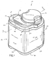
- FIG. 1 is a perspective view of a paint container.
- FIG. 2 is a side view of the paint container of FIG. 1.
- FIG. 3 is a top view of the paint container.
- FIG. 4 is a front view of the paint container.
- FIG. 5 is a front view of the paint container.
- FIG. 6 is a bottom view of the paint container.
- FIG. 7 is a cross-sectional view of the paint container taken generally along lines 7 - 7 of FIG. 1.
- FIG. 8 is bottom perspective view of the paint container.
- FIG. 9 is an exploded view of the paint container.
- FIG. 10 is a top view of the paint container without the cap.
- a paint container 10 includes a body 12 , a handle 14 , a cap or cover 16 , and a pour spout insert 18 .
- body 12 has a general D-shape configuration and includes a bottom 20 , a front wall 22 , a back wall 24 , and a pair of opposing side walls 26 , 28 .
- body 12 includes a top 30 having a land region 32 and a neck 34 with external threads 36 to secure the cap 16 .
- container 10 is formed from a plastic material that may be injection molded, blow molded, or injection blow molded. The container may be formed from any other method known in the art.
- Body 12 includes a recessed region 38 that extends across the front wall 22 , the side walls 26 , 28 and a portion of the curved back wall 24 .
- the recessed region 38 may receive a label that could be applied during the forming operation such as in the mold, or a label may be affixed to the container after the container has been formed.
- Body 12 further includes a first hand or top recess 40 located on the top edge of the container between the front wall 12 and the top 30 .
- Top recess 40 enables a user to easily access the handle 14 when the handle 14 is in a first or rest position adjacent the top 30 . A user can easily raise the handle 14 by simply sliding his or her hand within the recess under handle 14 .
- the top recess 40 may be fully covered by the handle 14 on the top of the container as illustrated in FIG. 3, or the recess may be accessible from the top of the container when the handle is in the rest position. This would allow a user to reach under the handle from either the front of the container or from the top of the container.
- a second hand or bottom recess 42 is located on the bottom edge of the container between the front wall 12 and the bottom 20 .
- the bottom or access recess 42 allows a user to reach under the bottom 20 of the container 10 while the container is resting on a supporting surface.
- the bottom recess 42 further facilitates pouring paint from the container.
- the bottom recess 42 is connected to a finger recess 44 via channel 46 on the bottom 20 of the container.
- the finger recess 44 allows a user to insert his or her fingers into the recess 44 to provide support for pouring paint from the container in combination with handle 14 .
- the height of the bottom recess 42 and channel 46 as measured from a supporting surface may be sufficient to allow a user to insert his or her fingers in the finger recess 44 while the container is on the support surface. This would aid in pulling a container off of the support surface or off of a lower container where the containers were stacked.
- Land 32 includes a pair of recess openings 48 to receive a pair of tabs 50 on handle 14 .
- land 32 could include tabs that would be received in apertures located in the handle 14 .
- the tabs and apertures allow the handle 14 to pivot about the land from the rest position to a carrying position or intermediate pouring position.
- Other mechanical fastening structures that are know in the art may also be employed.
- a snap in feature that releasably locks the handle 14 in the rest or in use position may be helpful to ensure the handle does not move.
- the snap or lock feature may be accomplished by irregular geometry of the handle tabs and land apertures, or any other known means for securing a handle in specific position relative to the container.
- the bottom 20 further includes additional recesses 52 , 54 to provide structural rigidity to the container.
- the recesses 52 and finger recess 44 extend into the container.
- the geometry of the recesses 52 should be such that a user can still access the paint on the inside of the container with a brush.
- the spaces between the recesses 44 and 52 should be sufficient to allow a user to access the paint between the resulting raised areas with a brush.
- the recesses may also be constructed to permit a top to bottom nesting feature with an adjacent stacked container.
- the bottom 20 also includes an outer periphery 56 that defines a plane that is parallel with the top of the cap 16 and top of the handle 14 for use in a compression type mixing apparatus.
- the portions 58 between the recesses 44 , 52 and 54 are in the same plane as the periphery 56 to provide additional support for the container.
- Handle 14 includes a top surface 60 , a front surface 62 , a rear surface 64 , and a pair of opposing side surfaces 66 , 68 . When the handle 14 is in the rest position, the front and side surfaces 62 , 66 and 68 are flush with the upper portion of the body.
- the handle may include a soft raised portion 69 that may be molded into the top surface 60 of the handle 14 .
- the handle 14 includes a lower contour 70 that substantially follows the contour of the land 32 and upper portion of the body 12 .
- cap 14 includes an outer wall 72 with inner threads 74 that allow the cap 14 to be threaded onto threads 36 of neck 34 .
- Cap 14 further includes an inner wall 76 extending from cap top 78 a distance greater than the distance that the outer wall 72 extends from the cap top 78 .
- Outer wall 72 includes a compression surface 80 that engages the top portion of neck 34 to seal the cap to the container. As the cap 14 is threaded onto the neck 34 , the inner wall 76 extends into the neck area of the container.
- Cap 14 further includes finger recesses 81 to facilitate closing and opening of the cap as well as holding the cap when the cap is being used as a paint dish.
- the top surface of cap 80 includes a substantially planar surface portion to enable the top to rest on a support surface to serve as a paint dish.
- the top of the cap includes geometry that enables the cap to rest on a support surface in a stable manner. This geometry could include a raised peripheral region.
- Finger recesses 81 form a land area 83 that facilitates use of the cap as a paint dish, since the land area allows for easy handling of the cap.
- Other embodiments of the cap could also be employed.
- the cap could include more than two finger recesses or could include a knurled outer surface to help facilitate tightening the cap onto the body or removing the cap from the body.
- the cap could be ergonomically designed to conform to the palm of a user's hand when the cap is being used as a paint dish.
- an inner wall 76 and outer wall 80 allows the cap to be used as a paint dish without the paint soiling the threads of the container, or dripping paint on to the outside of the body when the cap is secured to the body after it has been used as a container. Since the inner wall 76 extends beyond the outer wall, any paint that drips out of the cap when the cap is secured to the container will drip directly into the container. Additionally, any paint that drips into the channel 82 between the inner wall 76 and outer wall 72 will drip into the container between inner wall 76 and the spout insert 18 .
- the spout insert 18 includes an outer lip 84 that rests on the top rim 86 of the neck 34 of the body 12 . Insert 18 is secured to the body 12 by either an adhesive, friction fit, welding, or any other method known in the art. Insert includes an outer wall 88 and an inner wall 90 that includes a spout 92 . In one embodiment spout 92 extends upward above the outer lip 84 of the outer wall 88 . Spout 92 includes a “v” shaped recess with a circular recess 93 at the bottom portion of the “v”. Insert 18 includes an angled floor 94 connecting the inner wall 90 ad outer wall 88 .
- Floor 94 is angled downward from the rear wall 92 of the body and “v” region of the spout 92 toward the front wall 26 of the body 12 .
- Other spout configurations may also be employed.
- the shape of the spout recess could be a shape other than a “v” shape.
- the recess could be “U” shaped or rectangular.
- the spout could not include a recess portion at all but rather the spout could extend toward a single apex, where the apex is the highest of the spout and the paint is guided to pour over the apex.
- a channel 96 is formed between the inner wall 90 , and outer wall 88 .
- the angled floor 94 includes an opening 96 to connect the channel 96 with the interior of the container, to permit paint that drips over spout 92 to be reclaimed into the container via opening 96 .
- Insert 18 also includes a raised wipe portion 98 terminating in a straight edge 100 .
- the raised wipe portion 98 extends from the inner wall 90 into the opening 102 defined by the inner wall 98 and the straight edge 100 of the wiper portion 98 .
- the angle of the wipe potion 98 allows for reclamation of paint back into the container if the paint drips onto the top portion 99 of the wipe portion 98 .
- the opening 102 has a diameter of three and one half inches, allowing for easy insertion of a three inch brush.
- the straight edge has a width of at least three inches to permit the brush to be wiped along straight edge 100 without curving the bristles. It is possible to replace the straight edge with a comb or undulated edge feature.
- a comb feature could be releasably attached to the raised wipe portion to provide another type of wiping edge geometry if desired.
- the geometry of the opening 102 may be modified to allow for a larger or smaller brush width to enter the interior of the container to apply paint to a brush.
- the opening could be four inches or greater to allow for a four inch brush to be inserted.
- the “D” shape of the container allows for a convenient curved rear surface over which the paint is poured, and a substantially straight rear surface to allow for a label having a flat surface to be applied.
- the flat surface permits easier viewing of the label on the store shelf for the consumer. If the front of the container with the flat surface is facing the isle, the consumer can easily pick up the container by using both the handle 14 and the bottom finger recess 44 through recess 42 and channel 46 as discussed above.
- the curved rear surface guides the paint toward the spout 92 aiding in the removal of the last portion of paint in the container.
- the cap 16 is easily removed both in the retail outlet for easy tinting and at home or on the job site without requiring additional tools.
- the cap is screwed back on to the body of the container such that the top of the cap and the top surface of the handle are in the same plane. Since the top surface of the handle and cap are in a plane parallel to the button supporting surface, the paint in the container can then be mixed utilizing a standard mixing apparatus where the top and bottom of the container is trapped and compressed between two surfaces and subsequently shaken.
- the surface area of the handle and cap provide a stable surface for this type of compression apparatus.
- the container may employ other geometry to ensure that the container may be securely located in a compression type mixer.
- the mixer itself could employ a top member that matches the profile of the top of the container including the handle and cap.
- the container, cap and/or handle could include raised features to permit the top member of the mixer to effectively clamp onto the container for mixing.
- the geometry of the body facilitates access to the paint, once the level of paint drops. Since the recess 42 , channel 44 and finger recess 46 protrude into the interior of the container a greater amount than recesses 52 and 54 , a greater amount of paint will be in the region directly below the opening 102 to facilitate removal of the paint from the bottom of the container. Additionally, curved portion of the back wall 24 focuses the last amount of paint in a single area proximate the spout 92 , when the paint is being poured from the container.
- the container may also include features to promote stacking of the container.
- the container may include four small bumps on the bottom periphery that would act as feet and interlocking features with structure on the top of the container.
- the top of the container could include four small indents that would receive the bumps, or the bumps could be restrained from moving in a lateral direction by four offset guides.
- any locating feature could be arranged such that there is no impediment form sliding an upper stacked container off of a lower stacked container, by having the rear portion of the guides open.
- the raised portion or bumps could also be located on the top of the container and the recess or guides be located on the bottom of the container.
- the bumps could also be flexible such that they would be resiliently deflected when the container is clamped in a paint mixer that clamps the container on the top and bottom.
- a top member including one or more of the features discussed above such as the spout, reclamation structure, paint brush support, cap support, and others may be integrally formed with the body member or may be fastened to the container as a separate component.
- the container may include transparent areas to allow the user to see the contents of the container.
- the cap attachment may include a transparent area to indicate whether the cap is securely attached to the container to prevent paint from accidentally being spilled.
- the container has been referred to as a paint container other liquids may be stored and poured as well.
- the label that is applied to the container may include a blank white portion to permit the user or manufacture to dab or paint an sample of the paint in the container to clearly show what color is contained within the container and how it will appear when painted on a white background. It is also noted that the features described in the specification and shown in the Figures either alone or in combination may also be combined with individual or multiple features disclosed in the priority applications noted above. These and other modifications may be made in the design, arrangement and combination of the elements without departing from the scope of the invention as expressed in the appended claims.
Abstract
A plastic container set for holding paint is disclosed. The plastic container set comprises a first plastic container having a body with a first transverse cross dimension and a threaded upstanding collar defining an opening to the interior of the first container body. The plastic container set also comprises a second plastic container having a body with a second transverse cross dimension and a threaded upstanding collar defining an opening to the interior of the second container body. Further, the plastic container set comprises a cover having a top portion, a substantially circular annulus coupled to the top portion, the annulus defining the outer perimeter of the cover, the annulus having a diameter, and a thread inside the cover for coupling with the collar of both of the first plastic container and the second plastic container. The first transverse cross dimension is substantially the same as the diameter and the second transverse cross dimension is substantially greater than the diameter.
Description
- This application is a continuation of U.S. patent Application Ser. No. 10/006,985 entitled Paint Container, which is incorporated herein by reference; U.S. patent application Ser. No. 29/1 57,524 entitled Container, which is also incorporated herein by reference; U.S. patent application Ser. No. 29/159,661 entitled Container, which is further incorporated herein by reference; and U.S. patent application Ser. No. 10/132,682 entitled Container, which is further incorporated herein by reference.
- The present invention relates generally to the field of containers and more specifically a container for the distribution, sale, and use of paint.
- Typically, paint for application to a house or building for both interior and exterior applications is sold in a cylindrical one gallon metal container. The metal container includes a round base and a cylindrical side wall attached to and extending from the base. The side wall terminates in an upper rim or chime having a u-shaped channel that frictionally receives and engages a plug or lid having a downwardly extending u-shaped annular ring that is frictionally engaged by the walls of the u-shaped channel.
- The lid of a conventional paint container is removed by prying the annular ring out of the channel. This is accomplished by using a lever between an outer upper edge of the cylinder and the outer edge of the lid. In order to ensure that the lid does not fall off of the container, the channel of the container is sufficient to require the use of tools to remove the lid. Accordingly, a lever such as a screwdriver is used to pry the lid off of the upper rim by using the edge of the side wall as a fulcrum to apply sufficient force to the outer edge of the lid to remove the annular ring form the u-shaped channel. Depending on the amount of friction that must be overcome, a user usually has to apply pressure at a number of points about the circumference of the lid and container. The repeated insertion of the lever may result in damage to the lid or the coating on the inner surface of the metal lid that is intended to prevent rust or contamination of the paint.
- The paint may be poured from the container into a tray or other smaller container to be used by the painter to apply the paint to the intended surface either by brush, pad, roller or other mechanical or electrical system. Almost any time paint is poured, paint drips down the outside of the cylindrical wall and covers any identifying label. If the drips are significant, the paint may streak down the outer edge of the cylindrical wall and drip to the supporting surface that the paint container has been placed on. In any event, a certain amount of paint will be trapped within the u-shaped annular ring of the upper edge of the cylindrical side wall.
- When the lid is placed back onto the top of the container, the downwardly extending u-shaped ring on the lid will be soiled by the paint in the annular receiving area of the cylindrical wall. This creates a potential problem the next time the lid is removed and placed on a supporting surface. The paint on the annular surface may soil the surface upon which the paint lid rests or the hands of the user when they replace the lid again after use. If latex paint is in the container then the latex may dry in the channel and act as an adhesive between the lid and container making subsequent removal of the lid more difficult. The dried paint in the channel may prevent an air tight seal as result of paint buildup preventing the lid from being fully seated within the channel. Further, paint trapped in the channel may be splattered about the room when the lid is replaced and the trapped paint will likely spill over the edge and streak down the side of the container.
- Additionally, if the can itself is used as the container from which a brush is dipped by the painter, a significant amount of paint will accumulate in the channel as the brush is removed and excess paint is wiped against the edge of the can. Further, the inner annular edge of the container channel makes it difficult to uniformly wipe paint off of the brush. This results in an uneven application of paint on the brush and on the surface to be painted.
- Further the cylindrical container provides other disadvantages in the shipping, display and handling of the container by the end user. First, since the containers are round, the area between the cans represents wasted space when the container are shipped from the factory to the retail outlet. This wasted space must be paid for in terms of shipping costs. Similarly, shelf space at the retail outlet is wasted by the area between the cans. Since the cans are cylindrical, the label must also be cylindrical and therefore does not present the ideal display surface for the consumer at the retail outlet. As the consumer typically walks down the isle, the customer views the container at an angle which reveals only a portion of the label. Many display shelves also permit more than one can to be stacked in a front to back fashion. The cylindrical shape also limits the number of rows of cans that may be stacked on a display shelf.
- The handle of the typical paint container is a thin curved wire member comprised of a 0.105 gauge material that digs into the user's hand under the weight of the paint and the container. It is difficult to carry more than one paint container in each hand utilizing the curved wire. Additionally, the curved wire handle requires handle pivot or “ear” supports to be added to the outer surface of the cylindrical can. These pivot supports add assembly and material costs to the container. The pivot supports further affect how the containers must be packed for shipping and for display. Since the pivot supports extend outward from the container, additional space between products or placement such that the pivot supports are in the “dead” space zone between the containers is required.
- The cylindrical paint can does not provide a surface to support a paint brush. In order to balance a paint brush on the open container, the brush must be supported by two points on the outer lip. This is most easily accomplished with the bristles balanced at one point and the ferrule or handle balanced at another point. As discussed above, paint often collects in the channel of the container resulting in the ferrule or handle being soiled. Alternatively, if the channel does not contain paint, the placement of the bristles on the edge of the container will likely result in paint dripping into the channel and/or on to the edge of the container, which will likely soil the ferrule or handle if the ferrule or handle is subsequently placed on the soiled region.
- Paint that falls into the channel also presents a problem when the lid is being secured to the container after use. The paint in the channel is forced out of the channel as the annular ring of the lid is being located into the channel. Unless the lid is covered, the paint in the channel will splatter about the room as the lid is securely attached to the container. This result is due to the fact that the lid must be fully seated within the channel and a significant force is required. Typically a rubber mallet is used and the lid is struck a number of times with significant force.
- Another problem with the existing paint container is that if the paint is shaken in the container with the lid securely attached, the underside of the lid will become covered with paint and becomes difficult to handle when it is removed from the container.
- From the foregoing, it would be desirable to provide a paint container that would minimize shipping costs and permit a maximum number of containers to be stacked on a retail outlet shelf per linear foot of display. It would be further desirable to provide a product and method for displaying a paint product that allows for non-curved labeling. It would be desirable to provide a container that must be positioned correctly on the shelf, and is not easily rotated to a position that makes it difficult for a consumer to see the label. Another feature that would be desirable is a container system that facilitates stacking the containers one in front of the other.
- It would also be desirable to provide a container having a paint reclamation pouring mechanism in order to maintain a clean work area. It would also be desirable to provide a paint container that eliminates the need for handle supports or ears on the cylinder. It would also be desirable to provide a handle that is easy for the user to use and does not cut into the user's hand. Additionally, it would be desirable to provide a container with a lid that also serves as a paint container. It would still further be desirable to provide a lid that may be attached securely onto the container without the need for tools. It would also be desirable to provide a container with a spout that provides for a brush to be inserted into the container and includes a non-curved edge to provide for even wiping of the brush. It would also be desirable to provide a container that does not permanently dent when dropped or hit. It would also be desirable to provide secure surfaces for a container having one or more of the foregoing features to be employed in shaker equipment, to mix and or shake the paint. It would be desirable to provide a paint container with the foregoing features alone or in any combination.
- An exemplary embodiment relates to a plastic container set for holding paint. The plastic container set comprises a first plastic container having a body with a first transverse cross dimension and a threaded upstanding collar defining an opening to the interior of the first container body. The plastic container set also comprises a second plastic container having a body with a second transverse cross dimension and a threaded upstanding collar defining an opening to the interior of the second container body. Further, the plastic container set comprises a cover having a top portion, a substantially circular annulus coupled to the top portion, the annulus defining the outer perimeter of the cover, the annulus having a diameter, and a thread inside the cover for coupling with the collar of both of the first plastic container and the second plastic container. The first transverse cross dimension is substantially the same as the diameter and the second transverse cross dimension is substantially greater than the diameter.
- Another embodiment relates to a cover for a plastic container for holding paint. The plastic container comprises a top portion, a substantially circular annulus coupled to the top portion, the annulus defining the outer perimeter of the cover, and the annulus having a diameter, and a thread inside the cover. The cover is interchangeable with a first plastic container for holding paint, the first plastic container having a body with a transverse cross dimension that is substantially the same as the diameter and with a second plastic container for holding paint, the second plastic container body having a body with a transverse cross dimension that is substantially greater than the diameter.
- A further embodiment relates to a method of storing paint in containers of different sizes. The method comprises providing a first plastic container having a body with a first transverse cross dimension and a threaded upstanding collar defining an opening to the interior of the first container body, the first plastic container having a first volume. The method also comprises providing a second plastic container having a body with a second transverse cross dimension and a threaded upstanding collar defining an opening to the interior of the second container body, the second plastic container having a second volume. The method further comprises coupling a first cover on the first plastic container, the first cover having a top portion, a substantially circular annulus coupled to the top portion, the annulus defining the outer perimeter of the cover, and the annulus having a diameter, and a thread inside the cover for coupling with the collar of both of the first plastic container and the second plastic container. Further still, the method comprises coupling a second cover on the second plastic container, the second cover being of the same size as the first cover. The first transverse cross dimension is substantially the same as the diameter and the second transverse cross dimension is substantially greater than the diameter.
- Alternative exemplary embodiments relate to other features and combinations of features as may be generally recited in the claims.
- FIG. 1 is a perspective view of a paint container.
- FIG. 2 is a side view of the paint container of FIG. 1.
- FIG. 3 is a top view of the paint container.
- FIG. 4 is a front view of the paint container.
- FIG. 5 is a front view of the paint container.
- FIG. 6 is a bottom view of the paint container.
- FIG. 7 is a cross-sectional view of the paint container taken generally along lines 7-7 of FIG. 1.
- FIG. 8 is bottom perspective view of the paint container.
- FIG. 9 is an exploded view of the paint container.
- FIG. 10 is a top view of the paint container without the cap.
- Referring to FIG. 1 and FIG. 9, a
paint container 10 includes abody 12, ahandle 14, a cap or cover 16, and a pourspout insert 18. Referring to FIGS. 1-6,body 12 has a general D-shape configuration and includes a bottom 20, afront wall 22, aback wall 24, and a pair of opposingside walls body 12 includes a top 30 having aland region 32 and aneck 34 with external threads 36 to secure thecap 16. In one embodiment,container 10 is formed from a plastic material that may be injection molded, blow molded, or injection blow molded. The container may be formed from any other method known in the art. -
Body 12 includes a recessedregion 38 that extends across thefront wall 22, theside walls curved back wall 24. The recessedregion 38 may receive a label that could be applied during the forming operation such as in the mold, or a label may be affixed to the container after the container has been formed. -
Body 12 further includes a first hand ortop recess 40 located on the top edge of the container between thefront wall 12 and the top 30.Top recess 40 enables a user to easily access thehandle 14 when thehandle 14 is in a first or rest position adjacent the top 30. A user can easily raise thehandle 14 by simply sliding his or her hand within the recess underhandle 14. Thetop recess 40 may be fully covered by thehandle 14 on the top of the container as illustrated in FIG. 3, or the recess may be accessible from the top of the container when the handle is in the rest position. This would allow a user to reach under the handle from either the front of the container or from the top of the container. - A second hand or
bottom recess 42 is located on the bottom edge of the container between thefront wall 12 and the bottom 20. The bottom oraccess recess 42 allows a user to reach under the bottom 20 of thecontainer 10 while the container is resting on a supporting surface. Thebottom recess 42 further facilitates pouring paint from the container. Thebottom recess 42 is connected to afinger recess 44 viachannel 46 on the bottom 20 of the container. Thefinger recess 44 allows a user to insert his or her fingers into therecess 44 to provide support for pouring paint from the container in combination withhandle 14. Additionally, the height of thebottom recess 42 andchannel 46 as measured from a supporting surface may be sufficient to allow a user to insert his or her fingers in thefinger recess 44 while the container is on the support surface. This would aid in pulling a container off of the support surface or off of a lower container where the containers were stacked. -
Land 32 includes a pair ofrecess openings 48 to receive a pair oftabs 50 onhandle 14. Of course land 32 could include tabs that would be received in apertures located in thehandle 14. The tabs and apertures allow thehandle 14 to pivot about the land from the rest position to a carrying position or intermediate pouring position. Other mechanical fastening structures that are know in the art may also be employed. Additionally, a snap in feature that releasably locks thehandle 14 in the rest or in use position may be helpful to ensure the handle does not move. The snap or lock feature may be accomplished by irregular geometry of the handle tabs and land apertures, or any other known means for securing a handle in specific position relative to the container. - The bottom 20 further includes
additional recesses 52, 54 to provide structural rigidity to the container. The recesses 52 andfinger recess 44 extend into the container. The geometry of the recesses 52 should be such that a user can still access the paint on the inside of the container with a brush. The spaces between therecesses 44 and 52 should be sufficient to allow a user to access the paint between the resulting raised areas with a brush. The recesses may also be constructed to permit a top to bottom nesting feature with an adjacent stacked container. The bottom 20 also includes anouter periphery 56 that defines a plane that is parallel with the top of thecap 16 and top of thehandle 14 for use in a compression type mixing apparatus. Theportions 58 between therecesses periphery 56 to provide additional support for the container. -
Handle 14 includes atop surface 60, afront surface 62, arear surface 64, and a pair of opposing side surfaces 66, 68. When thehandle 14 is in the rest position, the front and side surfaces 62, 66 and 68 are flush with the upper portion of the body. The handle may include a soft raisedportion 69 that may be molded into thetop surface 60 of thehandle 14. Thehandle 14 includes alower contour 70 that substantially follows the contour of theland 32 and upper portion of thebody 12. - As illustrated in FIGS. 7 and 9,
cap 14 includes anouter wall 72 withinner threads 74 that allow thecap 14 to be threaded onto threads 36 ofneck 34.Cap 14 further includes aninner wall 76 extending from cap top 78 a distance greater than the distance that theouter wall 72 extends from the cap top 78.Outer wall 72 includes acompression surface 80 that engages the top portion ofneck 34 to seal the cap to the container. As thecap 14 is threaded onto theneck 34, theinner wall 76 extends into the neck area of the container.Cap 14 further includes finger recesses 81 to facilitate closing and opening of the cap as well as holding the cap when the cap is being used as a paint dish. The top surface ofcap 80 includes a substantially planar surface portion to enable the top to rest on a support surface to serve as a paint dish. Alternatively, the top of the cap includes geometry that enables the cap to rest on a support surface in a stable manner. This geometry could include a raised peripheral region. Finger recesses 81 form aland area 83 that facilitates use of the cap as a paint dish, since the land area allows for easy handling of the cap. Other embodiments of the cap could also be employed. For example, the cap could include more than two finger recesses or could include a knurled outer surface to help facilitate tightening the cap onto the body or removing the cap from the body. Further the cap could be ergonomically designed to conform to the palm of a user's hand when the cap is being used as a paint dish. - The use of an
inner wall 76 andouter wall 80 allows the cap to be used as a paint dish without the paint soiling the threads of the container, or dripping paint on to the outside of the body when the cap is secured to the body after it has been used as a container. Since theinner wall 76 extends beyond the outer wall, any paint that drips out of the cap when the cap is secured to the container will drip directly into the container. Additionally, any paint that drips into thechannel 82 between theinner wall 76 andouter wall 72 will drip into the container betweeninner wall 76 and thespout insert 18. - The
spout insert 18 includes anouter lip 84 that rests on thetop rim 86 of theneck 34 of thebody 12.Insert 18 is secured to thebody 12 by either an adhesive, friction fit, welding, or any other method known in the art. Insert includes anouter wall 88 and aninner wall 90 that includes aspout 92. In oneembodiment spout 92 extends upward above theouter lip 84 of theouter wall 88.Spout 92 includes a “v” shaped recess with acircular recess 93 at the bottom portion of the “v”.Insert 18 includes anangled floor 94 connecting theinner wall 90 adouter wall 88.Floor 94 is angled downward from therear wall 92 of the body and “v” region of thespout 92 toward thefront wall 26 of thebody 12. Other spout configurations may also be employed. For example the shape of the spout recess could be a shape other than a “v” shape. The recess could be “U” shaped or rectangular. Alternatively, the spout could not include a recess portion at all but rather the spout could extend toward a single apex, where the apex is the highest of the spout and the paint is guided to pour over the apex. - A
channel 96 is formed between theinner wall 90, andouter wall 88. Theangled floor 94 includes anopening 96 to connect thechannel 96 with the interior of the container, to permit paint that drips overspout 92 to be reclaimed into the container viaopening 96. -
Insert 18 also includes a raised wipeportion 98 terminating in astraight edge 100. The raised wipeportion 98 extends from theinner wall 90 into theopening 102 defined by theinner wall 98 and thestraight edge 100 of thewiper portion 98. The angle of the wipepotion 98 allows for reclamation of paint back into the container if the paint drips onto thetop portion 99 of the wipeportion 98. In one embodiment theopening 102 has a diameter of three and one half inches, allowing for easy insertion of a three inch brush. The straight edge has a width of at least three inches to permit the brush to be wiped alongstraight edge 100 without curving the bristles. It is possible to replace the straight edge with a comb or undulated edge feature. It is also contemplated that a comb feature could be releasably attached to the raised wipe portion to provide another type of wiping edge geometry if desired. The geometry of theopening 102 may be modified to allow for a larger or smaller brush width to enter the interior of the container to apply paint to a brush. For example the opening could be four inches or greater to allow for a four inch brush to be inserted. - The “D” shape of the container allows for a convenient curved rear surface over which the paint is poured, and a substantially straight rear surface to allow for a label having a flat surface to be applied. The flat surface permits easier viewing of the label on the store shelf for the consumer. If the front of the container with the flat surface is facing the isle, the consumer can easily pick up the container by using both the
handle 14 and thebottom finger recess 44 throughrecess 42 andchannel 46 as discussed above. The curved rear surface guides the paint toward thespout 92 aiding in the removal of the last portion of paint in the container. - The
cap 16 is easily removed both in the retail outlet for easy tinting and at home or on the job site without requiring additional tools. Once the tinting coloring has been added the cap is screwed back on to the body of the container such that the top of the cap and the top surface of the handle are in the same plane. Since the top surface of the handle and cap are in a plane parallel to the button supporting surface, the paint in the container can then be mixed utilizing a standard mixing apparatus where the top and bottom of the container is trapped and compressed between two surfaces and subsequently shaken. The surface area of the handle and cap provide a stable surface for this type of compression apparatus. The container may employ other geometry to ensure that the container may be securely located in a compression type mixer. The mixer itself could employ a top member that matches the profile of the top of the container including the handle and cap. The container, cap and/or handle could include raised features to permit the top member of the mixer to effectively clamp onto the container for mixing. - The geometry of the body facilitates access to the paint, once the level of paint drops. Since the
recess 42,channel 44 andfinger recess 46 protrude into the interior of the container a greater amount thanrecesses 52 and 54, a greater amount of paint will be in the region directly below theopening 102 to facilitate removal of the paint from the bottom of the container. Additionally, curved portion of theback wall 24 focuses the last amount of paint in a single area proximate thespout 92, when the paint is being poured from the container. - The container may also include features to promote stacking of the container. For example, the container may include four small bumps on the bottom periphery that would act as feet and interlocking features with structure on the top of the container. For example, the top of the container could include four small indents that would receive the bumps, or the bumps could be restrained from moving in a lateral direction by four offset guides. Of course there could be more or less than four locating features. Additionally, any locating feature could be arranged such that there is no impediment form sliding an upper stacked container off of a lower stacked container, by having the rear portion of the guides open. The raised portion or bumps could also be located on the top of the container and the recess or guides be located on the bottom of the container. The bumps could also be flexible such that they would be resiliently deflected when the container is clamped in a paint mixer that clamps the container on the top and bottom.
- Further modifications may be made in the design, arrangement and combination of the elements without departing from the scope of the invention as expressed in the appended claims For example a top member including one or more of the features discussed above such as the spout, reclamation structure, paint brush support, cap support, and others may be integrally formed with the body member or may be fastened to the container as a separate component. Additionally, the container may include transparent areas to allow the user to see the contents of the container. Further the cap attachment may include a transparent area to indicate whether the cap is securely attached to the container to prevent paint from accidentally being spilled. Although the container has been referred to as a paint container other liquids may be stored and poured as well. While some of the features have a unique application to the storage and application of paint, other features may be used for other liquids as well. Additionally, the label that is applied to the container may include a blank white portion to permit the user or manufacture to dab or paint an sample of the paint in the container to clearly show what color is contained within the container and how it will appear when painted on a white background. It is also noted that the features described in the specification and shown in the Figures either alone or in combination may also be combined with individual or multiple features disclosed in the priority applications noted above. These and other modifications may be made in the design, arrangement and combination of the elements without departing from the scope of the invention as expressed in the appended claims.
Claims (27)
1. A plastic container set for holding paint, comprising:
a first plastic container having a body with a first transverse cross dimension and a threaded upstanding collar defining an opening to the interior of the first container body;
a second plastic container having a body with a second transverse cross dimension and a threaded upstanding collar defining an opening to the interior of the second container body; and
a cover having a top portion, a substantially circular annulus coupled to the top portion, the annulus defining the outer perimeter of the cover, the annulus having a diameter, and a thread inside the cover for coupling with the collar of both of the first plastic container and the second plastic container,
wherein the first transverse cross dimension is substantially the same as the diameter and the second transverse cross dimension is substantially greater than the diameter.
2. The plastic container set of claim 1 , further comprising:
paint in the first and second plastic containers.
3. The plastic container set of claim 1 , wherein the first plastic container holds approximately one quart of paint and the second plastic container holds approximately one gallon of paint.
4. The plastic container set of claim 1 , wherein the cross-sectional shape of the first container is substantially D-shaped.
5. The plastic container set of claim 1 , wherein the cross-sectional shape of the second container is substantially D-shaped.
6. The plastic container set of claim 1 , further comprising:
an integral handle configured in the body of the first plastic container.
7. The plastic container set of claim 1 , further comprising:
a bail-type handle coupled to the second plastic container.
8. The plastic container set of claim 1 , wherein the diameter of the collar of the first and second plastic containers are at most approximately 4.5 inches each.
9. The plastic container set of claim 1 , further comprising:
a pour spout coupled to the collar of the second plastic container.
10. The plastic container set of claim 1 , further comprising:
an integral handle configured in the body of the first plastic container;
a bail-type handle coupled to the second plastic container; and
a pour spout coupled to the collar of the second plastic container,
wherein the cross-sectional shape of the first container is substantially D-shaped and the cross-sectional shape of the second container is substantially D-shaped.
11. A cover for a plastic container for holding paint, comprising:
a top portion;
a substantially circular annulus coupled to the top portion, the annulus defining the outer perimeter of the cover, and the annulus having a diameter;
a thread inside the cover,
wherein the cover is interchangeable with a first plastic container for holding paint, the first plastic container having a body with a transverse cross dimension that is substantially the same as the diameter and with a second plastic container for holding paint, the second plastic container body having a body with a transverse cross dimension that is substantially greater than the diameter.
12. The cover of claim 11 , further comprising:
a gripping portion coupled to the annulus, the gripping portion having at least one indentation provided for gripping the cover.
13. The cover of claim 12 , wherein there are a plurality of indentations spaced evenly around the gripping portion.
14. The cover of claim 11 , wherein the top portion is substantially flat.
15. The cover of claim 11 , wherein the top portion is curved.
16. The cover of claim 11 , wherein the top portion is domed.
17. The cover of claim 11 , further comprising:
a contour in the top portion for holding a brush.
18. The cover of claim 11 , wherein the cover is a different color than the body of at least one of the first plastic container and the second plastic container.
19. The cover of claim 11 , wherein the second plastic container has a pour spout.
20. A method of storing paint in containers of different sizes, comprising:
providing a first plastic container having a body with a first transverse cross dimension and a threaded upstanding collar defining an opening to the interior of the first container body, the first plastic container having a first volume;
providing a second plastic container having a body with a second transverse cross dimension and a threaded upstanding collar defining an opening to the interior of the second container body, the second plastic container having a second volume;
coupling a first cover on the first plastic container, the first cover having a top portion, a substantially circular annulus coupled to the top portion, the annulus defining the outer perimeter of the cover, and the annulus having a diameter, and a thread inside the cover for coupling with the collar of both of the first plastic container and the second plastic container; and
coupling a second cover on the second plastic container, the second cover being of the same size as the first cover,
wherein the first transverse cross dimension is substantially the same as the diameter and the second transverse cross dimension is substantially greater than the diameter.
21. The method of claim 20 , further comprising:
filling paint in the first and second plastic containers.
22. The method of claim 20 , wherein the first volume is approximately one quart and the second volume is approximately one gallon.
23. The method of claim 20 , wherein the cross-sectional shape of the first container is substantially D-shaped.
24. The method of claim 20 , wherein the cross-sectional shape of the second container is substantially D-shaped.
25. The method of claim 20 , further comprising:
screwing the first cover onto the first plastic container collar.
26. The method of claim 20 , further comprising:
screwing the second cover onto the second plastic container collar.
27. The method of claim 20 , further comprising:
coupling a pour spout to the second plastic container collar.
Priority Applications (1)
| Application Number | Priority Date | Filing Date | Title |
|---|---|---|---|
| US10/447,389 US20030192921A1 (en) | 2001-12-05 | 2003-05-29 | Interchangeable container cover |
Applications Claiming Priority (6)
| Application Number | Priority Date | Filing Date | Title |
|---|---|---|---|
| US10/006,985 US7036693B2 (en) | 2001-12-05 | 2001-12-05 | Paint container |
| US29/157,524 USD478820S1 (en) | 2002-03-20 | 2002-03-20 | Container |
| US29/159,661 USD497311S1 (en) | 2002-04-25 | 2002-04-25 | Container |
| US10/132,682 US7014078B2 (en) | 2001-12-05 | 2002-04-25 | Container |
| US10/255,564 US7156265B2 (en) | 2001-12-05 | 2002-09-25 | Container |
| US10/447,389 US20030192921A1 (en) | 2001-12-05 | 2003-05-29 | Interchangeable container cover |
Related Parent Applications (4)
| Application Number | Title | Priority Date | Filing Date |
|---|---|---|---|
| US10/006,985 Continuation US7036693B2 (en) | 2001-12-05 | 2001-12-05 | Paint container |
| US29/157,524 Continuation USD478820S1 (en) | 2001-12-05 | 2002-03-20 | Container |
| US29/159,661 Continuation USD497311S1 (en) | 2001-12-05 | 2002-04-25 | Container |
| US10/132,682 Continuation US7014078B2 (en) | 2001-12-05 | 2002-04-25 | Container |
Publications (1)
| Publication Number | Publication Date |
|---|---|
| US20030192921A1 true US20030192921A1 (en) | 2003-10-16 |
Family
ID=27358232
Family Applications (5)
| Application Number | Title | Priority Date | Filing Date |
|---|---|---|---|
| US10/006,985 Expired - Fee Related US7036693B2 (en) | 2001-12-05 | 2001-12-05 | Paint container |
| US10/132,682 Expired - Lifetime US7014078B2 (en) | 2001-12-05 | 2002-04-25 | Container |
| US10/255,564 Expired - Fee Related US7156265B2 (en) | 2001-12-05 | 2002-09-25 | Container |
| US10/447,389 Abandoned US20030192921A1 (en) | 2001-12-05 | 2003-05-29 | Interchangeable container cover |
| US11/351,323 Abandoned US20060273118A1 (en) | 2001-12-05 | 2006-02-09 | Container |
Family Applications Before (3)
| Application Number | Title | Priority Date | Filing Date |
|---|---|---|---|
| US10/006,985 Expired - Fee Related US7036693B2 (en) | 2001-12-05 | 2001-12-05 | Paint container |
| US10/132,682 Expired - Lifetime US7014078B2 (en) | 2001-12-05 | 2002-04-25 | Container |
| US10/255,564 Expired - Fee Related US7156265B2 (en) | 2001-12-05 | 2002-09-25 | Container |
Family Applications After (1)
| Application Number | Title | Priority Date | Filing Date |
|---|---|---|---|
| US11/351,323 Abandoned US20060273118A1 (en) | 2001-12-05 | 2006-02-09 | Container |
Country Status (9)
| Country | Link |
|---|---|
| US (5) | US7036693B2 (en) |
| EP (2) | EP1461257B1 (en) |
| CN (1) | CN100494005C (en) |
| AT (1) | ATE398084T1 (en) |
| AU (1) | AU2002351254A1 (en) |
| CA (1) | CA2469570A1 (en) |
| DE (1) | DE60227106D1 (en) |
| MX (1) | MXPA04005392A (en) |
| WO (1) | WO2003047982A2 (en) |
Cited By (6)
| Publication number | Priority date | Publication date | Assignee | Title |
|---|---|---|---|---|
| WO2007048681A1 (en) * | 2005-10-24 | 2007-05-03 | Akzo Nobel Coatings International B.V. | Lidded container |
| US20070221606A1 (en) * | 2006-03-23 | 2007-09-27 | Eiten Carl T | Liquid Container |
| US20080277418A1 (en) * | 2005-05-17 | 2008-11-13 | Rodney Alan Vockler | Container and a Fitting for a Container |
| US20090038271A1 (en) * | 2001-04-18 | 2009-02-12 | The Sherwin-Williams Company | Container and lid assembly and method of manufacture |
| US20120228331A1 (en) * | 2010-06-24 | 2012-09-13 | Kovrd Products Inc. | Modular paint spout |
| US20120325858A1 (en) * | 2011-06-23 | 2012-12-27 | Kovrd Products Inc. | Modular paint spout |
Families Citing this family (76)
| Publication number | Priority date | Publication date | Assignee | Title |
|---|---|---|---|---|
| US6068161A (en) * | 1997-07-01 | 2000-05-30 | Creative Edge Design Group, Ltd. | Stackable, thin-walled containers having a structural load distributing feature permitting caseless shipping |
| USD480973S1 (en) | 2001-08-14 | 2003-10-21 | Nsi Innovation Llp | Design for a round paint container |
| US7036693B2 (en) * | 2001-12-05 | 2006-05-02 | Masterchem Industries Llc | Paint container |
| US7207466B2 (en) * | 2001-12-05 | 2007-04-24 | Masterchem Industries Llc | Spout |
| EP1503647B1 (en) * | 2002-04-19 | 2010-03-03 | Rieke Corporation | Improved container for holding a product |
| US6896156B2 (en) * | 2002-07-03 | 2005-05-24 | The Sherwin-Williams Company | Plastic paint container having a cube-shaped body |
| US6997354B2 (en) * | 2002-07-19 | 2006-02-14 | Rieke Corporation | Sealing mechanisms for use in liquid-storage containers |
| US6843389B2 (en) * | 2002-07-19 | 2005-01-18 | Rieke Corporation | Sealing mechanisms for use in liquid-storage containers |
| US7347343B2 (en) * | 2002-07-19 | 2008-03-25 | Rieke Corporation | Container for liquids, including sealing mechanisms |
| USD499027S1 (en) | 2002-09-25 | 2004-11-30 | Masterchem Industries, Inc. | Container handle |
| FR2845315B1 (en) * | 2002-10-03 | 2004-11-12 | Impress Group Bv | MULTI-FUNCTION LIDS FOR CLOSING CONTAINERS, TYPICALLY PAINT JARS |
| US6945689B2 (en) * | 2003-04-18 | 2005-09-20 | Masterchem Industries, Llc | System for holding paint container |
| US20050023174A1 (en) * | 2003-05-12 | 2005-02-03 | Lary Banning Gray | Plastic stackable container assembly |
| US6945690B2 (en) * | 2003-05-29 | 2005-09-20 | Masterchem Industries, Inc. | System for holding paint container |
| US7467730B2 (en) * | 2003-07-09 | 2008-12-23 | Masterchem Industries, Llc | Paint container handle |
| US20050133518A1 (en) * | 2003-12-22 | 2005-06-23 | Daniel Chornenky | Modified paint can with pouredge and insert |
| KR20070017341A (en) * | 2004-03-27 | 2007-02-09 | 엥겔하드 코포레이션 | Container |
| US8002133B2 (en) * | 2004-03-27 | 2011-08-23 | Basf Corporation | Colorant container |
| US7654956B2 (en) * | 2004-07-13 | 2010-02-02 | Dexcom, Inc. | Transcutaneous analyte sensor |
| US20060096942A1 (en) * | 2004-11-05 | 2006-05-11 | Lane Dean V | Stackable bottle system |
| US7909201B2 (en) * | 2004-12-22 | 2011-03-22 | Daniel Chornenky | Paint can with pouredge |
| US20060144873A1 (en) * | 2004-12-28 | 2006-07-06 | Tiger Corporation | Liquid container |
| ATE401252T1 (en) * | 2005-01-14 | 2008-08-15 | Superfos As | CONTAINER |
| US7225939B2 (en) * | 2005-07-05 | 2007-06-05 | Conopco, Inc. | Assymetric handleware container having hidden gripping aperture |
| US10370142B2 (en) * | 2006-06-27 | 2019-08-06 | Stephen P. Palisin, Jr. | Shipping container |
| WO2007009076A2 (en) * | 2005-07-12 | 2007-01-18 | Nottingham Spirk Design Associates, Inc. | Polymeric cereal container as well as system and method utilizing same |
| US7611009B2 (en) * | 2005-09-27 | 2009-11-03 | Youngs Darren J | Paint tray with mechanically-opening lid |
| US20070108084A1 (en) * | 2005-11-17 | 2007-05-17 | Randall Susan M | Paint storage and touch-up container |
| US20070210123A1 (en) * | 2006-03-07 | 2007-09-13 | Penny Michael E | Container having blown pour spout |
| US20070235462A1 (en) * | 2006-03-17 | 2007-10-11 | Paul Omdoll | Container |
| US20070235477A1 (en) * | 2006-04-11 | 2007-10-11 | Penny Michael E | Container having blown pour spout |
| US7870979B2 (en) * | 2006-04-13 | 2011-01-18 | The Quaker Oats Company | Container with a scoopable and pourable spout |
| US20070262080A1 (en) * | 2006-05-12 | 2007-11-15 | Bologna James A | Lid assembly with tape roll holder |
| US8025183B2 (en) * | 2006-06-15 | 2011-09-27 | Plastek Industries, Inc. | Pour spout |
| US7686168B1 (en) * | 2006-10-10 | 2010-03-30 | Traex Company | Container |
| MX2009004698A (en) * | 2006-11-07 | 2009-05-21 | Graham Packaging Co | Plastic container and closure and system and method of making the same. |
| US8511499B2 (en) | 2007-12-18 | 2013-08-20 | Abbott Laboratories | Container |
| CA2674004C (en) * | 2006-12-27 | 2016-10-04 | Abbott Laboratories | Container |
| US20080156806A1 (en) * | 2006-12-27 | 2008-07-03 | Perry James P | Container with Sealing Wall |
| US20080156805A1 (en) * | 2006-12-27 | 2008-07-03 | Perry James P | Container with Gasket Seal |
| GB0707352D0 (en) * | 2007-04-17 | 2007-05-23 | Ici Plc | A Painting system |
| US20090072055A1 (en) * | 2007-09-19 | 2009-03-19 | Silgan Plastics Corporation | Shaker dispensing container |
| US7900469B2 (en) * | 2008-02-26 | 2011-03-08 | Champion Cooler Corporation | Evaporative cooler having a novel air flow pattern |
| USD643295S1 (en) | 2008-04-04 | 2011-08-16 | Mcneil-Ppc, Inc. | Bottle |
| US8104618B2 (en) * | 2008-04-04 | 2012-01-31 | Mcneil-Ppc, Inc. | Primary packaging and display therefor |
| GB2469479B (en) * | 2009-04-15 | 2013-04-10 | Akzo Nobel Coatings Int Bv | A painting apparatus |
| US8627981B2 (en) * | 2009-06-05 | 2014-01-14 | Abbott Laboratories | Container |
| US8469223B2 (en) * | 2009-06-05 | 2013-06-25 | Abbott Laboratories | Strength container |
| US20110017625A1 (en) * | 2009-07-22 | 2011-01-27 | Simplicity Products International, Inc. | Cubic eco-package for liquid products with finger engageable pull |
| US20110100856A1 (en) * | 2009-10-29 | 2011-05-05 | Michael Scot Rosko | Interlocking stacking container |
| KR20110009074U (en) * | 2010-03-17 | 2011-09-23 | 씨제이제일제당 (주) | Fluid storage tank |
| US20110315566A1 (en) * | 2010-06-29 | 2011-12-29 | Clever Girl Concepts, LLC | Customizable storage container system |
| US8887940B2 (en) * | 2010-08-16 | 2014-11-18 | Taras Kiceniuk, Jr. | Portable paint and tool container |
| US8777033B2 (en) | 2010-10-29 | 2014-07-15 | Graham Packaging Company, L.P. | Plastic container with reinforced base and closure and system and method of making same |
| CN104728750B (en) * | 2010-11-13 | 2017-12-19 | S·卡撒诺斯 | Adjustable solar charging electric light |
| US8919590B2 (en) * | 2010-12-29 | 2014-12-30 | Whirlpool Corporation | Mixing bowl liner and lid |
| US9637302B2 (en) * | 2011-09-13 | 2017-05-02 | Ring Container Technologies, Llc | Economically improved plastic bottle and package system |
| US9108757B2 (en) * | 2011-10-28 | 2015-08-18 | Raul M. Paredes | Container with pour spout |
| FR2983840B1 (en) * | 2011-12-12 | 2013-12-27 | Sidel Participations | STACKABLE CONTAINER COMPRISING A VOUTE BACK WITH A WIDE CONTACT SURFACE |
| IN2014DN08897A (en) | 2012-04-27 | 2015-05-22 | Abbott Lab | |
| US10232971B2 (en) * | 2013-03-08 | 2019-03-19 | Robert M. Jennings | Measuring and dispensing container |
| USD733320S1 (en) | 2013-04-26 | 2015-06-30 | Abbott Laboratories | Container |
| US9630446B1 (en) | 2015-08-13 | 2017-04-25 | Donald Kobasky | Paint can crown |
| USD824766S1 (en) * | 2016-03-25 | 2018-08-07 | The Sherwin-Williams Company | Storage container |
| USD801116S1 (en) * | 2016-04-27 | 2017-10-31 | Platinum Products, Llc | Portable hydration bottle |
| USD809097S1 (en) * | 2016-09-21 | 2018-01-30 | S. C. Johnson & Son, Inc. | Dispenser with container |
| US10836531B2 (en) * | 2016-11-04 | 2020-11-17 | Pepsico, Inc. | Plastic bottle with a champagne base and production methods thereof |
| USD873667S1 (en) * | 2017-07-10 | 2020-01-28 | The Sherwin-Williams Company | Storage container |
| US11033131B2 (en) * | 2017-09-29 | 2021-06-15 | Hanging Ip Llc | Glassware |
| US10167115B1 (en) | 2017-12-29 | 2019-01-01 | Buddeez, Inc. | Sealable container assembly with internal, removable panel and spout |
| US10464716B1 (en) * | 2018-05-22 | 2019-11-05 | The Procter & Gamble Company | Container having an adhesively attached fitment |
| DE102018120136A1 (en) * | 2018-08-17 | 2020-02-20 | Rickard Nilsson | Pushing device for exerting a compressive force against goods of a goods presentation device, shelf unit and goods presentation device |
| US11052701B2 (en) * | 2019-10-11 | 2021-07-06 | Adrien Casey | Paint can accessory |
| CN111114191B (en) * | 2019-12-28 | 2021-04-09 | 杭州欣禾工程管理咨询有限公司 | Architectural coatings storage box convenient to high altitude construction |
| CA3168733A1 (en) * | 2020-02-21 | 2021-08-26 | Jr. Grover J. Manderfield | Boxed container system |
| USD1012730S1 (en) | 2021-03-29 | 2024-01-30 | Swimc Llc | Storage container |
Citations (23)
| Publication number | Priority date | Publication date | Assignee | Title |
|---|---|---|---|---|
| US1768098A (en) * | 1929-01-22 | 1930-06-24 | Continental Can Co | Pouring spout for containers |
| US1794098A (en) * | 1929-03-29 | 1931-02-24 | Continental Can Co | Pouring spout for containers |
| US3158284A (en) * | 1961-03-30 | 1964-11-24 | Continental Can Co | Plastic handle and cleat attachment for containers |
| US4020975A (en) * | 1975-08-21 | 1977-05-03 | Stauffer R Thomas | Wall-mountable dispensing device for bulk and encapsulated materials |
| US4632888A (en) * | 1985-08-30 | 1986-12-30 | Gnb Incorporated | Battery carrying handle |
| US4696416A (en) * | 1984-09-28 | 1987-09-29 | The Procter & Gamble Company | Liquid product dispensing package with self draining feature employing drip concentrator |
| US4752543A (en) * | 1987-04-02 | 1988-06-21 | Anderson Carl J | Universal terminal storage battery with handle |
| US4805793A (en) * | 1987-10-23 | 1989-02-21 | Pioneer/Eclipse Corporation | Stackable bottle |
| US4844270A (en) * | 1988-06-13 | 1989-07-04 | Rampart Packaging Inc. | Screw cap jar |
| US4895269A (en) * | 1988-04-25 | 1990-01-23 | Cade Daniel W | Paint bucket |
| US5339487A (en) * | 1990-01-19 | 1994-08-23 | Rexair, Inc. | Filtering means for a liquid pan assembly for a liquid bath vacuum cleaner |
| US5415956A (en) * | 1991-04-29 | 1995-05-16 | Optima Batteries, Inc. | Cover assembly for rechargeable battery |
| US5436467A (en) * | 1994-01-24 | 1995-07-25 | Elsner; Norbert B. | Superlattice quantum well thermoelectric material |
| US5507543A (en) * | 1993-01-26 | 1996-04-16 | Shefflin; Joanne | Reusable container for carrying baby feeding products |
| US5579556A (en) * | 1995-12-14 | 1996-12-03 | Chung; Fu S. | Handle of a stroller |
| US5669526A (en) * | 1996-03-28 | 1997-09-23 | Keyfauver; Terry L. | Stackable spill proof paint can |
| US5678684A (en) * | 1995-08-11 | 1997-10-21 | Binney & Smith Inc. | Container for liquids |
| US5749652A (en) * | 1994-10-27 | 1998-05-12 | Red Devil Equipment Company | Mixing apparatus and method |
| US5794803A (en) * | 1996-11-01 | 1998-08-18 | Rexam Closures, Inc. | Child-resistant measuring cup closure and dispensing container |
| US5904269A (en) * | 1996-07-30 | 1999-05-18 | Rubbermaid Incorporated | Storage container |
| US5921448A (en) * | 1997-10-17 | 1999-07-13 | Stewart; Michael | Paint container lid |
| US20030102340A1 (en) * | 2001-12-05 | 2003-06-05 | Masterchem Industries, Inc. | Paint container |
| US6896156B2 (en) * | 2002-07-03 | 2005-05-24 | The Sherwin-Williams Company | Plastic paint container having a cube-shaped body |
Family Cites Families (201)
| Publication number | Priority date | Publication date | Assignee | Title |
|---|---|---|---|---|
| US1488397A (en) | 1924-03-25 | oe cincinnati | ||
| US2374430A (en) | 1945-04-24 | Paint dispensing apparatus | ||
| US164128A (en) | 1875-06-08 | Improvement in sirup-pitchers | ||
| US2743844A (en) | 1956-05-01 | livingstone | ||
| US1199680A (en) | 1914-01-31 | 1916-09-26 | Frederick H Fabian | Bail attachment. |
| US1196492A (en) | 1915-05-24 | 1916-08-29 | George Washington Sykes | Detachable handle or bail for containers and vessels. |
| US1448446A (en) | 1921-06-30 | 1923-03-13 | Pfister & Vogel Leather Compan | Mixing device |
| US1696240A (en) | 1926-11-05 | 1928-12-25 | Jr Albert G Kircher | Paint can |
| US1755763A (en) | 1927-11-23 | 1930-04-22 | James T Barber | Drum-washing machine |
| US1947398A (en) | 1931-08-18 | 1934-02-13 | Stuhler Martin | Agitating machine |
| US1893604A (en) | 1931-08-29 | 1933-01-10 | Surgident Ltd | Sanitary covered receptacle |
| US1873624A (en) * | 1932-01-26 | 1932-08-23 | John G Moxey | Measuring and dispensing device |
| US1952288A (en) | 1932-06-29 | 1934-03-27 | James R Saxon | Pouring attachment for cans |
| US2006451A (en) | 1933-01-02 | 1935-07-02 | United Shoe Machinery Corp | Receptacle holder |
| US2022527A (en) | 1934-09-29 | 1935-11-26 | Fred A Schletz | Mixing machine |
| US2120487A (en) | 1935-12-06 | 1938-06-14 | Wheeling Steel Corp | Container |
| US2077027A (en) | 1935-12-31 | 1937-04-13 | Torras Joaquin Vincent | Container |
| US2060932A (en) | 1936-02-25 | 1936-11-17 | Charles K Hullinger | Agitating apparatus |
| US2347401A (en) | 1940-12-09 | 1944-04-25 | Wilson & Bennett Mfg Co | Pail cover |
| US2324338A (en) | 1941-07-31 | 1943-07-13 | Newell R Tripp | Pouring can |
| US2387270A (en) | 1944-07-07 | 1945-10-23 | William B Johnson | Container |
| US2661872A (en) * | 1949-10-24 | 1953-12-08 | Heintz Mfg Co | Container |
| US2601039A (en) | 1949-12-01 | 1952-06-17 | Livingstone Jay Gould | Pouring spout |
| US2787402A (en) | 1952-04-16 | 1957-04-02 | Color Carousel Corp | Liquid proportioning and dispensing apparatus |
| US2763402A (en) | 1952-06-10 | 1956-09-18 | Livingstone Jay Gould | Adapter |
| US2763403A (en) | 1953-06-16 | 1956-09-18 | Jay G Livingstone | Fittings |
| US2848019A (en) | 1953-10-27 | 1958-08-19 | Color Carousel Corp | Paint mixing machine |
| US2851196A (en) | 1954-01-11 | 1958-09-09 | Jay G Livingstone | Adapter |
| US2690281A (en) | 1954-04-02 | 1954-09-28 | Livingstone Jay Gould | Capped vessel with adapter |
| US2797902A (en) | 1955-05-13 | 1957-07-02 | Samuel B Beugler | Mixing machine |
| US2889079A (en) | 1955-09-22 | 1959-06-02 | Livingstone Jay Gould | Adapter and adapter combination |
| US2848142A (en) | 1956-02-20 | 1958-08-19 | Jay G Livingstone | Container |
| US2921330A (en) | 1957-03-11 | 1960-01-19 | Prytikin George | Attachment for a paint can or the like |
| US2894309A (en) | 1957-12-10 | 1959-07-14 | Harry S Brzowski | Container clamp for liquid mixing apparatus |
| US3066830A (en) | 1958-02-24 | 1962-12-04 | Valspar Corp | Dispensing machine |
| US3018092A (en) | 1958-06-12 | 1962-01-23 | Harold T Johnson | Paint-can shaker |
| US2935223A (en) | 1958-07-30 | 1960-05-03 | Jerome J Crowley | Can bail construction |
| US3074597A (en) | 1958-11-21 | 1963-01-22 | Microdot Inc | Pigment measuring and dispensing device |
| US3015415A (en) | 1960-02-25 | 1962-01-02 | Marien Metal Products Co | Mixing and dispensing apparatus |
| US3122272A (en) | 1960-08-04 | 1964-02-25 | Marsh Lyle | Fluid dispenser |
| US3138284A (en) | 1961-04-12 | 1964-06-23 | Continental Can Co | Bail attachment for can tops |
| US3085710A (en) | 1961-12-06 | 1963-04-16 | Frieda A Mcilroy | Attachment for drinking container |
| US3220048A (en) | 1964-02-10 | 1965-11-30 | Wei Tohchung | Detachable handle for stacked food vessels |
| US3291295A (en) | 1964-05-13 | 1966-12-13 | Gerald J Caligiuri | Paint container and brush holder |
| US3214052A (en) | 1964-08-10 | 1965-10-26 | Climalene Company | Bottle construction |
| US3275366A (en) | 1965-02-23 | 1966-09-27 | Walter E Hidding | Plastic carrier for bottles |
| US3307752A (en) | 1965-03-15 | 1967-03-07 | Johnson & Son Inc S C | Captive plastic closure for container with integral container handle |
| US3301534A (en) | 1965-03-22 | 1967-01-31 | Chamberlain Corp | Paint shaker machine |
| CH435556A (en) | 1965-04-26 | 1967-05-15 | Ruetz Joseph | Drop insert for a container |
| US3298561A (en) | 1965-06-04 | 1967-01-17 | Arthur E Mcconnie | Combined paint can cover and brush wiper |
| US3284057A (en) | 1965-07-07 | 1966-11-08 | Robert J Duquette | Combination paint mixing and can closing devices |
| US3300104A (en) | 1965-07-09 | 1967-01-24 | Procter & Gamble | Pouring adapter for liquid containers |
| US3292815A (en) | 1965-08-05 | 1966-12-20 | Wooster Brush Co | Pail |
| US3387749A (en) | 1966-10-06 | 1968-06-11 | Bennett Ind Inc | Plastic containers |
| US3412887A (en) | 1967-02-07 | 1968-11-26 | Ira T. Swartwood | Plastic bottle |
| US3451590A (en) | 1967-06-21 | 1969-06-24 | Eastman Kodak Co | Recessed handle assembly |
| US3419196A (en) * | 1967-10-19 | 1968-12-31 | Carnation Co | Plastic pail with bail having two interchangeable positions |
| US3463366A (en) | 1968-01-24 | 1969-08-26 | Francis D Spencer | Paint can attachment ring with pouring lip |
| US3590416A (en) * | 1968-11-14 | 1971-07-06 | Painter Corp E Z | Paint tray and pail combination |
| US3542344A (en) | 1969-07-09 | 1970-11-24 | Dynatech Corp | Method and apparatus for mixing flowable materials in closed containers |
| BE757851A (en) | 1969-10-23 | 1971-04-01 | Focke Heinz | PACKAGING IN CARTON OR CORRUGATED CARTON AND INTENDED FOR BOTTLES OR THE LIKE |
| US3612595A (en) | 1969-11-12 | 1971-10-12 | Haynes Mfg Co The | Container handle |
| US3659758A (en) | 1969-12-10 | 1972-05-02 | Atlantic Design & Dev Corp | Sliding top internal pourer bottle cap |
| US3679103A (en) | 1970-03-06 | 1972-07-25 | John F Chmela | Combination carrying handle and pour spout |
| US3620410A (en) | 1970-04-20 | 1971-11-16 | Nat Can Corp | Plastic bail for container and method of attaching bail |
| US3695488A (en) | 1970-10-26 | 1972-10-03 | Sven O Olsson | Container spout |
| NL7108244A (en) | 1971-06-16 | 1971-08-25 | ||
| US3727792A (en) | 1971-06-30 | 1973-04-17 | E Z Por Corp | Attachment to rim of a paint can or the like |
| US3744671A (en) | 1971-10-08 | 1973-07-10 | H Saunders | Open container adaptor |
| US3735962A (en) | 1971-11-23 | 1973-05-29 | Raymond Lee Organization Inc | Automatic jar shaker |
| US3735964A (en) | 1972-02-07 | 1973-05-29 | R K Lorenzen | Powered mechanical shaker device |
| US3866791A (en) | 1972-05-17 | 1975-02-18 | Roper Frank | Container and cover including corner pouring and bail nesting features |
| US3807679A (en) | 1972-08-04 | 1974-04-30 | Burron Medical Prod Inc | One piece molded bottle band |
| US3853249A (en) | 1973-04-02 | 1974-12-10 | C Weir | Pouring spout for cans |
| US3924775A (en) * | 1973-06-04 | 1975-12-09 | Weston Instruments Inc | Positively lockable angularly adjustable handle |
| US3980213A (en) | 1973-06-12 | 1976-09-14 | Three Dimensional Circuits, Inc. | Covers for paint cans |
| FI49000C (en) | 1973-08-09 | 1975-03-10 | Winter Oy | Mixing device for paints, in particular paints and their shades. |
| US3942688A (en) | 1974-06-27 | 1976-03-09 | Umc Industries, Inc. | Post-mix vendor syrup tank |
| US4078700A (en) | 1974-08-05 | 1978-03-14 | Hidding Walter E | Dripless pouring spout and closure cap therefor |
| US3899107A (en) | 1974-08-12 | 1975-08-12 | Denes Gaal | Paint can adaptor |
| US3945527A (en) | 1974-10-30 | 1976-03-23 | Pylant Andrew A | Paint brush wiping device |
| US3972453A (en) | 1975-06-20 | 1976-08-03 | Kapples Lawrence J | Combined closure and pouring device |
| US4009802A (en) | 1975-09-02 | 1977-03-01 | Leon Hayduchok | Paint can attachment |
| US4014465A (en) | 1975-09-02 | 1977-03-29 | Ritter John C | Paint can pour spout |
| GB1516415A (en) | 1975-10-14 | 1978-07-05 | Ho Hoi | Combined closure and pouring device for a container |
| US4061242A (en) | 1976-08-11 | 1977-12-06 | Donlon Joseph J | Dripless paint container |
| US4033473A (en) | 1976-09-20 | 1977-07-05 | Rheem Manufacturing Company | Molded plastic container |
| US4118801A (en) | 1976-11-05 | 1978-10-03 | Kraft Jack A | Rack for vessels and means for agitating the vessels in the rack |
| US4128189A (en) | 1977-04-04 | 1978-12-05 | National Plastics Corporation | Device for improving the pourability of fluids and also forming an improved closure for a container of such fluids |
| US4125210A (en) | 1977-07-26 | 1978-11-14 | Lawrence Peska Associates, Inc. | Attachment for paint cans |
| US4203537A (en) | 1977-08-25 | 1980-05-20 | Plastic-Craft, Inc. | Paint can accessory |
| US4164299A (en) * | 1977-10-14 | 1979-08-14 | Fuhr Patti S | Tray for paint and brushes |
| AU526813B2 (en) | 1978-02-24 | 1983-02-03 | Innovative Design Co. Pty. Ltd. | Method of connecting a bail to a container |
| US4189804A (en) | 1978-03-24 | 1980-02-26 | Keeler Corporation | Back plate and bail assembly |
| US4150763A (en) | 1978-04-03 | 1979-04-24 | Simpson Catherine L | Paint brush scraper |
| US4240568A (en) | 1978-06-05 | 1980-12-23 | Robert R. Pool | Attachment for liquid carrying container |
| USD258563S (en) | 1978-06-29 | 1981-03-17 | Romagnoli G Franco | Container for liquids |
| CA1132534A (en) | 1978-09-25 | 1982-09-28 | John C. Gall | Material tumbler with non-perpendicular rotation axes |
| US4235348A (en) | 1979-01-18 | 1980-11-25 | Watson Lionel E | Drinking vessels for reclining position usage |
| US4225064A (en) | 1979-01-25 | 1980-09-30 | Richard Westcott | Painter's accessory |
| JPS6020599Y2 (en) | 1979-03-09 | 1985-06-20 | 固 飯田 | Injection barrel of injection container |
| FI58264C (en) | 1979-05-10 | 1981-01-12 | Winter Oy | MASKIN FOER NYANSERING AV MAOLFAERGER |
| US4266686A (en) | 1979-07-02 | 1981-05-12 | Carter Joseph F | Paint can attachment for holding brushes |
| USD261362S (en) | 1979-08-10 | 1981-10-20 | Invention Development Equity Assoc., Inc. | Stackable container for liquids or the like |
| US4312459A (en) | 1979-09-27 | 1982-01-26 | Leach Albert E | Paint can rim cover and lid combination |
| US4281936A (en) | 1979-11-13 | 1981-08-04 | Red Devil, Inc. | Paint mixing and conditioning machine |
| US4497581A (en) | 1979-11-15 | 1985-02-05 | Miller Paint Equipment, Inc. | Paint shaker |
| US4387828A (en) | 1980-02-11 | 1983-06-14 | Yates Jr George | Plastic container and lid |
| USD267631S (en) | 1980-04-16 | 1983-01-18 | The Procter & Gamble Company | Bottle |
| US4329068A (en) | 1980-04-21 | 1982-05-11 | Neuner Terry E | Mixing machine |
| US4351454A (en) * | 1980-07-16 | 1982-09-28 | Maynard Jr Walter P | Liquid container having stacking feature |
| US4440328A (en) | 1982-01-26 | 1984-04-03 | Termolar S/A | Wide-mouthed isothermal container with integrated handle equipped with immersed pump |
| US4474303A (en) | 1981-08-28 | 1984-10-02 | Maccise Adiv Y | Portable modular food container |
| IT8221696V0 (en) | 1982-04-27 | 1982-04-27 | Gargioni Domenico | MIXER APPARATUS, IN PARTICULAR FOR THE MIXING OF PAINT PRODUCTS OR SIMILAR SUSPENSIONS. |
| US4399926A (en) | 1982-04-29 | 1983-08-23 | Eidels Dubovoy Samuel | Resealable easy-opening container |
| US4520936A (en) | 1982-05-20 | 1985-06-04 | Polybottle | Blow moulded plastic containers |
| USD276890S (en) | 1982-05-24 | 1984-12-25 | Hancher Jon W | Jug |
| US4446986A (en) | 1982-08-02 | 1984-05-08 | Genpak Corporation | Fluid tight container and closure assembly |
| US4445782A (en) | 1982-08-27 | 1984-05-01 | Peerless Pressed Metal, Inc. | Apparatus for shaking contained mixtures including paint and other fluid materials |
| US4550862A (en) | 1982-11-17 | 1985-11-05 | The Procter & Gamble Company | Liquid product pouring and measuring package with self draining feature |
| US4512494A (en) * | 1983-02-28 | 1985-04-23 | Holdt J W Von | Plastic container having tongue and groove retention |
| USD279763S (en) | 1983-03-18 | 1985-07-23 | Bomatic, Inc. | Container for paint or the like |
| US4583666A (en) | 1983-03-21 | 1986-04-22 | Buck Donald C | Container attachment |
| US4541529A (en) | 1983-07-19 | 1985-09-17 | Bomatic, Inc. | Blow molded container and supplemental handle therefor |
| IT8420420V0 (en) | 1984-01-04 | 1984-01-04 | Fast Spa | DEVICE FOR THE QUICK LOCKING OF CONTAINERS, IN MIXING APPLIANCES FOR THE MIXING OF PAINT PRODUCTS, OR SUSPENSIONS AND SIMILAR. |
| USD288535S (en) | 1984-09-11 | 1987-03-03 | John Bozich | Pouring attachment for a can or the like |
| US4702395A (en) | 1984-09-24 | 1987-10-27 | Reinhold Nitsch | Paint can handle and spout attachment |
| USD292490S (en) * | 1984-10-09 | 1987-10-27 | The Procter & Gamble Company | Pouring attachment for bottles |
| USD292491S (en) | 1984-10-09 | 1987-10-27 | The Proctor & Gamble Company | Pouring attachment for bottles |
| USD292489S (en) | 1984-10-09 | 1987-10-27 | The Proctor & Gamble Company | Pouring attachment for bottles |
| USD292492S (en) | 1984-10-09 | 1987-10-27 | The Procter & Gamble Company | Combined closure and measuring cup |
| USD289377S (en) | 1984-10-12 | 1987-04-21 | Tone Brothers, Inc. | Bottle or similar article |
| US4713064A (en) | 1985-04-30 | 1987-12-15 | Sherwood Medical Company | Enteral feeding devices |
| USD296420S (en) | 1985-09-09 | 1988-06-28 | Frahm Carl E | Bottle |
| USD296671S (en) | 1985-09-30 | 1988-07-12 | Jordan Alfred R | Storage container for hypodermic syringes |
| US4615456A (en) | 1985-10-04 | 1986-10-07 | Robert Cousar | Combination brush holder and tray |
| CA1236040A (en) * | 1985-10-31 | 1988-05-03 | C. Bruce Hewson | Fermentation vessel |
| US4706829A (en) | 1986-02-07 | 1987-11-17 | Owens-Illinois Closure Inc. | Liquid containing and dispensing package |
| US4671421A (en) | 1986-03-06 | 1987-06-09 | Owens-Illinois, Inc. | Plastic container |
| US4993565A (en) * | 1986-04-14 | 1991-02-19 | Yoshino Kogyosho Co., Ltd. | Biaxial-orientation blow-molded bottle-shaped container having opposed recesses and grooves for stable gripping and anti-buckling stiffness |
| USD304296S (en) | 1986-07-29 | 1989-10-31 | Robert Wilson | Combined bottle and handle |
| DE3626154A1 (en) | 1986-08-01 | 1988-02-04 | Henkel Kgaa | MEASURING CUP CLOSURE AND METHOD FOR MOUNTING THE CLOSURE |
| USD302526S (en) | 1986-09-05 | 1989-08-01 | Ritter John C | Combined pouring spout and cover |
| USD304014S (en) | 1986-11-05 | 1989-10-17 | Thomas Industries Inc. | Paint container |
| US4736874A (en) | 1986-11-24 | 1988-04-12 | Durant Will G | Apparatus for use on open-mouth cans for pouring liquid therefrom |
| US4865282A (en) | 1986-12-31 | 1989-09-12 | Yonkman Robert K | Paint roller wiper with paintbrush holder |
| US4927046A (en) | 1987-01-05 | 1990-05-22 | Armstrong Robert E | Holding vessel with supportive handle |
| US4771501A (en) | 1987-03-20 | 1988-09-20 | Leiter Thomas E | Brush holder |
| GB2206095B (en) | 1987-06-16 | 1991-01-02 | Metal Box Co Ltd | Securing handles to plastics containers |
| JPH0751481Y2 (en) | 1987-06-17 | 1995-11-22 | 株式会社資生堂 | Liquid container outlet plug |
| FR2617133B1 (en) | 1987-06-25 | 1990-01-26 | Astra Plastique | METERING CAP FOR CONTAINER WITH THREADED NECK AND SIDE HANDLE |
| US4895415A (en) | 1987-11-09 | 1990-01-23 | Ford Motor Company | Vehicle wheel cover and assembly |
| US4892207A (en) | 1988-03-28 | 1990-01-09 | The Perrier Group Of America, Inc. | Bottled water container |
| US4917268A (en) | 1988-06-20 | 1990-04-17 | The Clorox Company | Liquid dispensing package with drainback spout |
| US4893723A (en) | 1988-06-28 | 1990-01-16 | Seabolt John K | Paint can attachment |
| US4993605A (en) | 1988-11-16 | 1991-02-19 | Colgate-Palmolive Company | Closure assembly with pouring spout and measuring cup |
| US4941586A (en) | 1989-01-18 | 1990-07-17 | Sarvis Oy | Container |
| USD323115S (en) * | 1989-03-17 | 1992-01-14 | Crown Berger Europe Ltd. | Container for paint or the like |
| GB2229987B (en) * | 1989-03-21 | 1992-12-16 | Crown Berger Europ | Containers for liquids |
| US4911319A (en) | 1989-03-31 | 1990-03-27 | Dejean Milton V | Paint can attachment |
| USD318228S (en) * | 1989-08-11 | 1991-07-16 | American National Can Co. | Bottle |
| US4928839A (en) | 1989-09-08 | 1990-05-29 | The Dow Chemical Company | Plastic drums for storing or transporting liquid and solid products |
| US4949884A (en) | 1989-12-11 | 1990-08-21 | Dahl Gordon T | Paint can lid with drip-free pour spout |
| US4984714A (en) | 1990-01-09 | 1991-01-15 | Specialty Packaging Licensing Company | Spouted bottle |
| US5012960A (en) | 1990-01-30 | 1991-05-07 | Arnold Samuel C | Groove protector and spout |
| US5078289A (en) * | 1990-03-15 | 1992-01-07 | Kraft General Foods, Inc. | Container with measuring cup closure |
| USD355366S (en) * | 1991-03-22 | 1995-02-14 | Imperial Chemical Industries Plc | Container |
| USD332747S (en) * | 1991-09-11 | 1993-01-26 | Plastipak Packaging, Inc. | Bottle with handle |
| US5199570A (en) * | 1991-12-02 | 1993-04-06 | Bonar Inc. | Liquid transportation container |
| GB2262929A (en) * | 1991-12-30 | 1993-07-07 | Lin Pac Mouldings | Container assembly |
| DE4236484A1 (en) * | 1992-10-29 | 1994-05-05 | Berolina Kunststoff | Bottle crate |
| US5316054A (en) * | 1993-04-30 | 1994-05-31 | The Procter & Gamble Company | Self-contained package for housing, dispensing and diluting concentrated liquid |
| US5449087A (en) * | 1993-09-08 | 1995-09-12 | Sonoco Products Company | Molded plastic drum |
| GB2281894B (en) * | 1993-09-16 | 1997-10-08 | Ici Plc | Combination of a paint container, lid and a paint-roller tray |
| GB2284587B (en) * | 1993-12-10 | 1997-04-30 | Lin Pac Mouldings | A container and handle assembly |
| USD374178S (en) * | 1994-01-18 | 1996-10-01 | Fiskars Inc. | Paint container |
| US5535910A (en) * | 1994-02-25 | 1996-07-16 | Tucker Housewares | Stakable refuse container with improved handle and lid drain |
| US5400916A (en) * | 1994-03-01 | 1995-03-28 | Weber; Daniel C. | Paint roller bucket |
| US5435467A (en) * | 1994-04-20 | 1995-07-25 | Phoenix Closures, Inc. | Stackable dispenser closure |
| USD370153S (en) * | 1994-05-23 | 1996-05-28 | Rubbermaid Specialty Products Inc. | Beverage container |
| AUPM809794A0 (en) * | 1994-09-14 | 1994-10-06 | Jones, Peter Timothy | A container |
| US5850939A (en) * | 1995-07-05 | 1998-12-22 | Spector; Donald | Squeeze canteen for soft drink |
| US5709314A (en) * | 1996-03-01 | 1998-01-20 | Petry; Robert W. | Stackable container with an easy clean seal |
| US5850953A (en) * | 1997-01-28 | 1998-12-22 | Aptargroup, Inc. | Drip-free dispensing structure with collecting reservoir |
| US5938080A (en) * | 1997-02-21 | 1999-08-17 | The Geon Company | System and apparatus for dispensing high-viscosity pigments |
| US6068161A (en) * | 1997-07-01 | 2000-05-30 | Creative Edge Design Group, Ltd. | Stackable, thin-walled containers having a structural load distributing feature permitting caseless shipping |
| US5941422A (en) * | 1998-04-06 | 1999-08-24 | Owens-Brockway Plastic Products Inc. | Liquid containing and dispensing package |
| US6029858A (en) * | 1998-05-01 | 2000-02-29 | Srokose; John S. | Jug and method |
| US6085949A (en) * | 1998-05-05 | 2000-07-11 | Liquid Container L.P. | Container with molded-in directional pour guide |
| US6237792B1 (en) * | 1999-01-19 | 2001-05-29 | State Industrial Products | Reinforced bottle having integral handles |
| US6213338B1 (en) * | 1999-03-05 | 2001-04-10 | James E. Cogdill | Brush scraper for paint cans |
| US6210382B1 (en) * | 1999-05-04 | 2001-04-03 | Chadwick B. Hogg | Emesis device |
| US6257401B1 (en) * | 1999-05-14 | 2001-07-10 | Pactiv Corporation | Vented container with handles and embossment |
| US6530500B2 (en) * | 1999-07-08 | 2003-03-11 | The Sherwin-Williams Company | Storage and dispensing container for viscous fluids, paints and the like, and method of minimizing dripping |
| US6138963A (en) * | 1999-08-23 | 2000-10-31 | Malvasio; William A. | Paint cup and brush holder |
| US6412661B1 (en) * | 1999-09-09 | 2002-07-02 | Robert E. Hannah, Sr. | Plastic paint container with redundant closure, spill resistant pour spout and liquid recovery |
| US6269962B1 (en) * | 2000-01-21 | 2001-08-07 | Colgate-Palmolive Company | Enhanced strength container |
| CA2449416C (en) * | 2001-04-18 | 2011-02-22 | Nottingham-Spirk Partners, Llc | Improved container and lid assembly |
| USD480973S1 (en) * | 2001-08-14 | 2003-10-21 | Nsi Innovation Llp | Design for a round paint container |
| USD474115S1 (en) * | 2002-03-20 | 2003-05-06 | Masterchem Industries, Inc. | Container |
| USD475628S1 (en) * | 2002-04-25 | 2003-06-10 | Masterchem Industries, Inc. | Container |
-
2001
- 2001-12-05 US US10/006,985 patent/US7036693B2/en not_active Expired - Fee Related
-
2002
- 2002-04-25 US US10/132,682 patent/US7014078B2/en not_active Expired - Lifetime
- 2002-09-25 US US10/255,564 patent/US7156265B2/en not_active Expired - Fee Related
- 2002-12-05 AU AU2002351254A patent/AU2002351254A1/en not_active Abandoned
- 2002-12-05 CA CA002469570A patent/CA2469570A1/en not_active Abandoned
- 2002-12-05 MX MXPA04005392A patent/MXPA04005392A/en active IP Right Grant
- 2002-12-05 EP EP02786902A patent/EP1461257B1/en not_active Expired - Lifetime
- 2002-12-05 CN CNB02827847XA patent/CN100494005C/en not_active Expired - Fee Related
- 2002-12-05 DE DE60227106T patent/DE60227106D1/en not_active Expired - Fee Related
- 2002-12-05 WO PCT/US2002/038952 patent/WO2003047982A2/en not_active Application Discontinuation
- 2002-12-05 AT AT02786902T patent/ATE398084T1/en not_active IP Right Cessation
- 2002-12-05 EP EP08008998A patent/EP1955953A3/en not_active Withdrawn
-
2003
- 2003-05-29 US US10/447,389 patent/US20030192921A1/en not_active Abandoned
-
2006
- 2006-02-09 US US11/351,323 patent/US20060273118A1/en not_active Abandoned
Patent Citations (23)
| Publication number | Priority date | Publication date | Assignee | Title |
|---|---|---|---|---|
| US1768098A (en) * | 1929-01-22 | 1930-06-24 | Continental Can Co | Pouring spout for containers |
| US1794098A (en) * | 1929-03-29 | 1931-02-24 | Continental Can Co | Pouring spout for containers |
| US3158284A (en) * | 1961-03-30 | 1964-11-24 | Continental Can Co | Plastic handle and cleat attachment for containers |
| US4020975A (en) * | 1975-08-21 | 1977-05-03 | Stauffer R Thomas | Wall-mountable dispensing device for bulk and encapsulated materials |
| US4696416A (en) * | 1984-09-28 | 1987-09-29 | The Procter & Gamble Company | Liquid product dispensing package with self draining feature employing drip concentrator |
| US4632888A (en) * | 1985-08-30 | 1986-12-30 | Gnb Incorporated | Battery carrying handle |
| US4752543A (en) * | 1987-04-02 | 1988-06-21 | Anderson Carl J | Universal terminal storage battery with handle |
| US4805793A (en) * | 1987-10-23 | 1989-02-21 | Pioneer/Eclipse Corporation | Stackable bottle |
| US4895269A (en) * | 1988-04-25 | 1990-01-23 | Cade Daniel W | Paint bucket |
| US4844270A (en) * | 1988-06-13 | 1989-07-04 | Rampart Packaging Inc. | Screw cap jar |
| US5339487A (en) * | 1990-01-19 | 1994-08-23 | Rexair, Inc. | Filtering means for a liquid pan assembly for a liquid bath vacuum cleaner |
| US5415956A (en) * | 1991-04-29 | 1995-05-16 | Optima Batteries, Inc. | Cover assembly for rechargeable battery |
| US5507543A (en) * | 1993-01-26 | 1996-04-16 | Shefflin; Joanne | Reusable container for carrying baby feeding products |
| US5436467A (en) * | 1994-01-24 | 1995-07-25 | Elsner; Norbert B. | Superlattice quantum well thermoelectric material |
| US5749652A (en) * | 1994-10-27 | 1998-05-12 | Red Devil Equipment Company | Mixing apparatus and method |
| US5678684A (en) * | 1995-08-11 | 1997-10-21 | Binney & Smith Inc. | Container for liquids |
| US5579556A (en) * | 1995-12-14 | 1996-12-03 | Chung; Fu S. | Handle of a stroller |
| US5669526A (en) * | 1996-03-28 | 1997-09-23 | Keyfauver; Terry L. | Stackable spill proof paint can |
| US5904269A (en) * | 1996-07-30 | 1999-05-18 | Rubbermaid Incorporated | Storage container |
| US5794803A (en) * | 1996-11-01 | 1998-08-18 | Rexam Closures, Inc. | Child-resistant measuring cup closure and dispensing container |
| US5921448A (en) * | 1997-10-17 | 1999-07-13 | Stewart; Michael | Paint container lid |
| US20030102340A1 (en) * | 2001-12-05 | 2003-06-05 | Masterchem Industries, Inc. | Paint container |
| US6896156B2 (en) * | 2002-07-03 | 2005-05-24 | The Sherwin-Williams Company | Plastic paint container having a cube-shaped body |
Cited By (12)
| Publication number | Priority date | Publication date | Assignee | Title |
|---|---|---|---|---|
| US20090038271A1 (en) * | 2001-04-18 | 2009-02-12 | The Sherwin-Williams Company | Container and lid assembly and method of manufacture |
| US20080277418A1 (en) * | 2005-05-17 | 2008-11-13 | Rodney Alan Vockler | Container and a Fitting for a Container |
| WO2007048681A1 (en) * | 2005-10-24 | 2007-05-03 | Akzo Nobel Coatings International B.V. | Lidded container |
| US20080308556A1 (en) * | 2005-10-24 | 2008-12-18 | Akzo Nobel Coating International B.V. | Lidded Container |
| JP2009512598A (en) * | 2005-10-24 | 2009-03-26 | アクゾ ノーベル コーティングス インターナショナル ビー ヴィ | Container with lid |
| AU2006308076B2 (en) * | 2005-10-24 | 2011-07-28 | Akzo Nobel Coatings International B.V. | Lidded container |
| US8157122B2 (en) | 2005-10-24 | 2012-04-17 | Akzo Nobel Coatings International B.V. | Lidded container |
| KR101276598B1 (en) * | 2005-10-24 | 2013-06-19 | 아크조노벨코팅스인터내셔널비.브이. | Lidded container |
| NO340153B1 (en) * | 2005-10-24 | 2017-03-13 | Akzo Nobel Coatings Int Bv | Container with lid |
| US20070221606A1 (en) * | 2006-03-23 | 2007-09-27 | Eiten Carl T | Liquid Container |
| US20120228331A1 (en) * | 2010-06-24 | 2012-09-13 | Kovrd Products Inc. | Modular paint spout |
| US20120325858A1 (en) * | 2011-06-23 | 2012-12-27 | Kovrd Products Inc. | Modular paint spout |
Also Published As
| Publication number | Publication date |
|---|---|
| AU2002351254A1 (en) | 2003-06-17 |
| US20030102340A1 (en) | 2003-06-05 |
| ATE398084T1 (en) | 2008-07-15 |
| CN1622899A (en) | 2005-06-01 |
| EP1461257B1 (en) | 2008-06-11 |
| WO2003047982A3 (en) | 2003-10-30 |
| EP1461257A2 (en) | 2004-09-29 |
| MXPA04005392A (en) | 2004-10-11 |
| US20030121941A1 (en) | 2003-07-03 |
| WO2003047982A2 (en) | 2003-06-12 |
| US20030102339A1 (en) | 2003-06-05 |
| CA2469570A1 (en) | 2003-06-12 |
| US7014078B2 (en) | 2006-03-21 |
| CN100494005C (en) | 2009-06-03 |
| EP1955953A2 (en) | 2008-08-13 |
| EP1955953A3 (en) | 2008-11-05 |
| US20060273118A1 (en) | 2006-12-07 |
| DE60227106D1 (en) | 2008-07-24 |
| AU2002351254A8 (en) | 2003-06-17 |
| US7156265B2 (en) | 2007-01-02 |
| EP1461257A4 (en) | 2005-04-27 |
| US7036693B2 (en) | 2006-05-02 |
Similar Documents
| Publication | Publication Date | Title |
|---|---|---|
| US7014078B2 (en) | Container | |
| US20040240314A1 (en) | System for holding paint container | |
| US7207466B2 (en) | Spout | |
| US7434706B2 (en) | Container and lid assembly | |
| US8123066B2 (en) | Container | |
| US7658299B2 (en) | Sealable paint tray assembly | |
| US20040206761A1 (en) | Handheld container with removable divider | |
| CA2561666C (en) | Paint container and lid assembly | |
| US6105816A (en) | Painter's aid | |
| JP2007509829A (en) | Container sealing system | |
| MXPA06000784A (en) | Spout | |
| WO2006061019A2 (en) | A paint tray and a packaging | |
| CA2481963A1 (en) | Handheld container with removable divider |
Legal Events
| Date | Code | Title | Description |
|---|---|---|---|
| AS | Assignment |
Owner name: MASTERCHEM INDUSTRIES LLC, MISSOURI Free format text: ASSIGNMENT OF ASSIGNORS INTEREST;ASSIGNOR:MASTERCHEM BRANDS, INC.;REEL/FRAME:016643/0204 Effective date: 20040316 Owner name: MASTERCHEM BRANDS, INC., MISSOURI Free format text: CHANGE OF NAME;ASSIGNOR:MASTERCHEM INDUSTRIES, INC.;REEL/FRAME:016643/0150 Effective date: 20040224 |
|
| STCB | Information on status: application discontinuation |
Free format text: ABANDONED -- FAILURE TO RESPOND TO AN OFFICE ACTION |