US20030192932A1 - Tool with nosepiece for bending fastener upon installation and fastener therefor - Google Patents
Tool with nosepiece for bending fastener upon installation and fastener therefor Download PDFInfo
- Publication number
- US20030192932A1 US20030192932A1 US10/424,515 US42451503A US2003192932A1 US 20030192932 A1 US20030192932 A1 US 20030192932A1 US 42451503 A US42451503 A US 42451503A US 2003192932 A1 US2003192932 A1 US 2003192932A1
- Authority
- US
- United States
- Prior art keywords
- fastener
- workpiece
- formation
- nosepiece
- deformation
- Prior art date
- Legal status (The legal status is an assumption and is not a legal conclusion. Google has not performed a legal analysis and makes no representation as to the accuracy of the status listed.)
- Granted
Links
Images


Classifications
-
- B—PERFORMING OPERATIONS; TRANSPORTING
- B25—HAND TOOLS; PORTABLE POWER-DRIVEN TOOLS; MANIPULATORS
- B25C—HAND-HELD NAILING OR STAPLING TOOLS; MANUALLY OPERATED PORTABLE STAPLING TOOLS
- B25C5/00—Manually operated portable stapling tools; Hand-held power-operated stapling tools; Staple feeding devices therefor
- B25C5/02—Manually operated portable stapling tools; Hand-held power-operated stapling tools; Staple feeding devices therefor with provision for bending the ends of the staples on to the work
- B25C5/0207—Particular clinching mechanisms
-
- B—PERFORMING OPERATIONS; TRANSPORTING
- B25—HAND TOOLS; PORTABLE POWER-DRIVEN TOOLS; MANIPULATORS
- B25C—HAND-HELD NAILING OR STAPLING TOOLS; MANUALLY OPERATED PORTABLE STAPLING TOOLS
- B25C5/00—Manually operated portable stapling tools; Hand-held power-operated stapling tools; Staple feeding devices therefor
- B25C5/06—Manually operated portable stapling tools; Hand-held power-operated stapling tools; Staple feeding devices therefor without provision for bending the ends of the staples on to the work
- B25C5/08—Manually operated portable stapling tools; Hand-held power-operated stapling tools; Staple feeding devices therefor without provision for bending the ends of the staples on to the work with means for forming the staples in the tool
- B25C5/085—Manually operated portable stapling tools; Hand-held power-operated stapling tools; Staple feeding devices therefor without provision for bending the ends of the staples on to the work with means for forming the staples in the tool starting from performed staples
-
- B—PERFORMING OPERATIONS; TRANSPORTING
- B25—HAND TOOLS; PORTABLE POWER-DRIVEN TOOLS; MANIPULATORS
- B25C—HAND-HELD NAILING OR STAPLING TOOLS; MANUALLY OPERATED PORTABLE STAPLING TOOLS
- B25C5/00—Manually operated portable stapling tools; Hand-held power-operated stapling tools; Staple feeding devices therefor
- B25C5/16—Staple-feeding devices, e.g. with feeding means, supports for staples or accessories concerning feeding devices
- B25C5/1665—Staple-feeding devices, e.g. with feeding means, supports for staples or accessories concerning feeding devices with means for preventing jamming or aiding unjamming within the drive channel
Definitions
- the present invention relates generally to fastener driving tools used for driving fasteners into workpieces to secure materials to the workpieces (referred to as workpiece materials), and specifically to fastener driving tools configured for driving two-legged fasteners, one example of such being referred to as a staple.
- Conventional fastener driving tools feature a reciprocating driver blade which impacts a fastener fed to a nosepiece by a magazine. Whether powered pneumatically, manually, by combustion or electricity, such tools provide sufficient force to the driver blade that it separates the fastener from adjacent fasteners in the magazine, and drives the fastener so that the fastener is sufficiently embedded in the workpiece.
- two-legged fasteners include a pair of separated, generally parallel legs separated by a crown to form an inverted “U”-shape. Such fasteners are typically used in the installation of workpiece materials such as asphalt roofing shingles, building siding, wallboard, Romex® wire, Nomex® wire, Tyvek® insulation wrap, other insulation felts and other similar applications.
- workpiece materials such as asphalt roofing shingles, building siding, wallboard, Romex® wire, Nomex® wire, Tyvek® insulation wrap, other insulation felts and other similar applications.
- One operational problem of two-legged fasteners is that the legs are sometimes driven too deeply into the workpiece, causing the crown to pierce the surface of the workpiece material. When this happens, the workpiece material is not as securely held. In other words, the amount of force needed to pull the workpiece material away from the workpiece (“pull through”) decreases when the workpiece material has been pierced. A side effect of this piercing is that the workpiece material may be damaged.
- a fastener driving tool configured for driving a fastener so that, upon impact with the workpiece or substrate, the fastener has a nonlinear shape projecting transversely to a plane of the fastener for providing increased clamping force.
- Another advantage of the nonlinear fastener shape described above is the resistance to penetrating the workpiece material.
- the tool drives the fastener by impacting the crown near the leg portion without contacting the clamping portion of the fastener crown.
- a fastener driving tool having a reciprocating driver blade and a nosepiece, and being configured for sequentially feeding fasteners to the nosepiece for engagement by the driver blade for subsequent driving into a workpiece.
- Each of the fasteners defines a plane.
- the tool further includes a deformation formation in the nosepiece configured for engaging a portion of each of the fasteners, so that upon impact of the fastener by the driver blade, the engaged fastener portion is deformed in a direction transverse to the plane to attain a deformed condition.
- the deformed condition of the deformation portion of the fastener is configured for providing a clamping force upon workpiece material secured to the workpiece.
- a fastener for use in such a tool having a reciprocating driver blade and a nosepiece with a deformation formation, the tool being configured for sequentially feeding the fasteners to the nosepiece for engagement by the driver blade and impacting upon the deformation formation for subsequent driving into a workpiece and deformation.
- the fastener includes a pair of legs each having a lower end configured for entering a workpiece, and a crown disposed between and joining the legs and being configured so that, upon impact with the deformation formation with workpiece material secured to the workpiece, the crown has a nonlinear configuration and includes a portion which projects from a plane defined by legs.
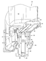
- FIG. 1 is a fragmentary front perspective view of a fastener driving tool featuring the present deformation formation
- FIG. 2 is a fragmentary exploded view of the operation of the driver blade of the present tool upon the present fastener which is being driven into a workpiece;
- FIG. 3 is a front elevational view of the present fastener
- FIG. 4 is a top perspective view of the present fastener prior to being driven
- FIG. 5 is a top perspective view of an alternate embodiment of the present fastener
- FIG. 6 is a top perspective view of a nosepiece back plate of the present tool
- FIG. 7 is a front elevational view of the back plate of FIG. 6;
- FIG. 8 is a side elevational view thereof
- FIG. 9 is a rear elevational view thereof
- FIG. 10 is a top perspective view of the present deformation formation
- FIG. 11 is a fragmentary vertical cross-section of the deformation formation in the nosepiece
- FIG. 12 is a schematic side view of the present fastener shown in various operational positions
- FIGS. 13 - 16 are vertical cross-sections of the present nosepiece in a fastener-driving sequence
- FIG. 17 is a fragmentary cross-section of a workpiece having the present fastener driven therein;
- FIG. 18 is a fragmentary cross-section of a workpiece including a cable attached to a substrate
- FIG. 19 is a fragmentary front elevational view of the present tool driving the present fastener with an optional standoff fitting
- FIG. 20 is a fragmentary front elevational view of an alternate embodiment to the present fastener
- FIG. 21 is a fragmentary front elevational view of a second alternate embodiment of the present fastener.
- FIG. 22 is a fragmentary front elevational view of a third alternate embodiment of the present fastener.
- a fastener driving tool suitable for use with the present invention is generally designated 10 and includes a housing 12 enclosing a reciprocating driver blade 14 , and a magazine 16 configured for providing a sequence of fasteners for driving.
- the tool 10 may be pneumatic, combustion-powered, manual, electrically-powered or powder activated, and a variety of such configurations of such tools are known in the art. Examples of such tools are sold under the trademark PASLODE® by Illinois Tool Works, Inc., the present assignee.
- a nosepiece 18 receives fasteners through a fastener opening 20 , and is configured for positioning a next-to-be-driven fastener 22 a for engagement by the descending driver blade 14 .
- the fastener preferred for use in the tool 10 is a two-legged fastener 22 , in some cases known as a staple, having two legs 24 , each leg having a point 26 shaped to pierce and become embedded in a workpiece 28 and joined together by a crown 30 .
- the crown is generally linear or straight, and the fastener forms an inverted “U”-shape.
- the present fastener 22 is provided with a crown 30 that is less likely to pierce or damage workpiece material 32 which is to be attached to the workpiece 28 , and also which has relatively greater clamping force over the workpiece material 32 than standard inverted “U”-shaped fasteners.
- the workpiece material 32 is intended to be attached to the workpiece or substrate 28
- the fastener legs 24 are configured, depending on the type of material, to either penetrate or avoid the material 32 and penetrate the substrate, while the crown 30 typically is designed to hold the material against the substrate.
- the present crown 30 includes a pair of shoulders 36 separated by a deformation portion 38 . While it is contemplated that the deformation portion 38 may have a variety of shapes, as is discussed below, it is preferred that the portion defines a general “V” configuration which depends from the shoulders 36 and is generally coplanar with the fastener 22 . As an alternative, and referring to FIG. 5, it is also contemplated that a fastener 39 may be provided to the tool 10 in a format in which, prior to driving, the deformation portion 38 a projects at an angle to the plane of the fastener. As will be seen below, the deformation portion 38 provides enhanced clamping force over conventional staples, and, at the same time, reduces the possibility that the workpiece material 32 will be pierced or otherwise damaged in the fastener driving operation.
- the present nosepiece 18 includes a back plate 40 , a front plate 42 and a workpiece contact element 44 .
- the nosepiece 18 is preferably configured so that the front plate 42 is pivotably mounted to the back plate 40 so that the front plate may be displaced from the back plate to remove jammed fasteners or to make other necessary adjustments.
- the back and front plates 40 , 42 combine to form a driver blade passageway 46 when they are held together in an operational position (best seen in FIGS. 13 - 16 ) by a latch mechanism 48 .
- the fastener opening 20 is located in the back plate 40 and permits the sequential passage of fasteners 22 from the magazine 16 .
- the workpiece contact element 44 (best seen in FIG. 1) is slidably mounted to the front plate 42 to trigger operational prefiring or pre-driving sequences as is well known in the art.
- the tool 10 Prior to driving the fastener 22 , the tool 10 is pressed against the workpiece 28 so that the workpiece contact element 44 is depressed and moves (usually upward) relative to the front plate 42 .
- the tool 10 will be described in a normal operational position relative to the workpiece 28 as shown in FIG. 1, with the tool above the workpiece, it is also contemplated that the present tool may be operated in an inverted position over the user's head for ceiling work or other overhead work, as well as other orientations known to skilled operators in the art.
- a leading edge 50 of the workpiece contact element has a notch 52 .
- the tool 10 may be equipped with a depth of drive adjustment 54 which allows the user to change the depth the fastener 22 is driven into the workpiece 28 or to adjust for variable fastener lengths, as is known in the art.
- an important feature of the present tool 10 is that the nosepiece 18 is provided with a deformation formation 56 configured to receive the fastener 22 , deform the deformation portion 38 and thus protect the workpiece material 32 from penetration by the crown 30 .
- Another function of the present deformation formation 56 is to provide additional clamping force by the fastener 22 upon the workpiece material 32 which is enhanced over conventional “U”-shaped staple-type fasteners. The latter function is provided by deforming the deformation portion 38 , or providing a pre-deformed deformation portion 38 a, so that it has an increased “footprint”, or covers a relatively large area of the workpiece material 32 , compared to conventional staples.
- Still another feature of the present tool is that the clamping force provided by the fastener 22 is independent of the depth to which the fastener legs 24 have been driven into the workpiece 28 .
- FIGS. 13 - 16 depict a sequential operational cycle of the driving of a single fastener
- the fastener 22 defines a plane (FIG. 13).
- the deformation portion 38 of the crown 30 is deformed in a direction which projects from the fastener plane.
- the projection is generally transverse to the fastener plane, and at the conclusion of the deformation process, the crown 30 attains a deformed condition. It is contemplated that the amount of transverse angular deformation relative to the plane may vary to suit the application, and deformations in the range of 30°-120° are contemplated.
- the deformed condition of the deformation portion 38 is achieved through interaction of the fastener 22 and the nosepiece 18 of the tool. More specifically, the driver blade 14 is provided with a lower impact edge 58 having two tabs 60 separated by a notch or recess 62 . The recess 62 is dimensioned for accommodating the deformation formation 56 . Once the tool 10 is fired, initiating the fastener driving operation, the driver blade 14 is propelled down the driver blade passageway 46 .
- the tabs 60 impact corresponding shoulders 36 of the next-to-be-driven fastener 22 a, separating it from the remaining fasteners in the magazine 16 and driving the fastener 22 a towards the deformation formation 56 , and ultimately, the workpiece 28 , securing the workpiece material 32 thereto.
- the fastener legs 24 pass the deformation formation 56 on either side, and enter the workpiece 28 .
- the configuration of the fastener 22 is such that the legs 24 are substantially embedded in the workpiece material 32 and the workpiece 28 before the crown 30 engages the deformation formation 56 .
- the crown 30 engages a ramp portion 64 which deforms the deformation portion 38 , forcing it to project from, and preferably transversely out of the plane of, the fastener 22 .
- the driver blade 14 does not directly engage the deformation portion 38 , the driving force applied to the shoulders 36 , and the sloping, arcuate, radiused or inclined shape of the ramped portion 64 cause the deformation portion to attain the deformed condition shown in FIGS. 2, 12, 16 and 17 .
- the driver blade 14 is prevented from driving the fastener 22 further into the substrate 28 by one or more of the interaction of the tab 60 , the shoulders 36 and the substrate, the engagement between the recess 62 and the deformation formation 56 , and the depth of drive mechanism 54 . It will be appreciated that the notch 52 in the workpiece contact element 44 is configured for also accommodating the deformation formation 56 .
- the deformed condition provides increased clamping force in the form of a larger footprint on the workpiece material 32 compared to standard, linear crown staples, while avoiding the potential for the crown 30 to pierce the material.
- the ramp portion 64 forms a wedge-like shape or point 65 which contributes to the shape attained by the deformation portion 38 upon impact with the substrate material 32 .
- the deformation formation 56 includes a toe portion 66 located beneath the ramp portion which actually contacts the workpiece 28 or workpiece material 32 in most applications.
- the height of the toe portion 66 may vary to suit the application, depending on the type of material 32 being secured to the substrate 34 .
- the height of the toe portion 66 relative to the geometry of the ramp portion 64 may be varied to adjust the amount of clamping force applied by the fastener 22 .
- the formation includes at least one fastening structure 68 extending laterally from the formation. As shown in FIG. 10, the formation 56 has a general “T” shape when viewed from above.
- the nosepiece includes a notch 69 in at least one of the back plate 40 and the front plate 42 for accommodating the deformation formation 56 .
- the orientation of the ramp portion 64 and the formation 56 in general may change depending on whether it is attached to the back plate 40 or the front plate 42 .
- Each fastening structure 68 has at least one fastening formation 70 for securing the formation 56 to one of the back plate 40 and the front plate 42 .
- the formation 56 is secured to the back plate 40
- the fastening formation 70 is an eyelet dimensioned for receiving a fastener 72 which also engages the back plate.
- the specific fastening technology may vary depending on the particular application.
- the deformation formation 56 may be adjusted laterally relative to the nosepiece to vary a point “P” on the ramped portion 64 where the driver blade 14 intersects (FIG. 11). In this manner, the degree of deformation of the deformation portion 38 may be varied. Thus, deformation at a point P 1 will be greater than at a point P 2 . Accordingly, one or more spacers 73 may be disposed or removed between the fastening structure 68 and a rear surface 74 of the back plate 40 to adjust the lateral disposition of the ramp formation 64 relative to the driver blade passageway 46 . While in the above description, the deformation formation 56 is releasably attached to the nosepiece 18 , it is also contemplated that the formation may be integrally secured thereto.
- the nosepiece 18 is optionally provided with a guide 76 which is configured for limiting the penetration of the driver blade 14 into the workpiece, and thus creating a standoff of the crown away from the substrate 28 a sufficient distance to prevent the crown from piercing the workpiece material 32 .
- the deformation portion 38 still exerts sufficient clamping force on the workpiece material 32 that the cable or wire is held in place (best seen in FIG. 18).
- Another function of the guide 76 is to protect the workpiece material 32 from unwanted contact or damage caused by the fastener legs 24 .
- the guide 76 is preferably secured to a bottom of the nosepiece 18 by suitable releasable fasteners, by chemical adhesives or by welding, depending on the application. Included on the guide 76 is an upper-most support surface 78 which engages the nosepiece 18 , and at least one and preferably two depending legs 80 which together define a distance or separation space 82 between the workpiece 28 and the nosepiece 18 sufficient to accommodate the workpiece material 32 . Also, the legs 80 are preferably spaced apart sufficiently to accommodate the workpiece material 32 a therebetween. The legs 80 thus protect the workpiece material 32 a from damage or unwanted contact with the fastener legs 24 . In the preferred embodiment, the guide 76 defines a generally inverted “U”-shape, however other shapes are contemplated depending on the application, provided sufficient separation space 82 is defined.
- the support surface 78 receives the impact of the driver blade 14 through contact with the tabs 60 to prevent further penetration of the legs 24 into the workpiece 28 .
- the deformation portion 38 is manipulated to project from the plane of the fastener 22 to provide a clamping force upon the wire or cable 32 .
- the deformation portion 38 be deformed so that a maximum surface area or footprint is contacting the workpiece material 32 (best seen in FIG. 17), it is contemplated that increased clamping force is still obtained when the angular displacement is greater or less than 90°. It will be seen in FIGS. 12 and 18 that a material 32 a is sti sufficiently engaged by the deformation portion 38 to clamp it to the substrate 28 , even-though the angular displacement is greater than 90°. Conversely, in applications where the driver blade does not drive the legs 24 as far into the substrate 28 , the deformation may be less than 90°, as seen in the case of the substrate 32 b and the deformation portion 38 b (FIGS.
- the amount of angular deformation of the deformation portion 38 from the plane of the fastener 22 is determined in part by the configuration of the workpiece material 32 itself, in combination with the configuration of the deformation formation 56 . However, the amount of deformation is independent of the force provided to the shoulders 36 .
- the fastener 22 may be provided in a variety of configurations in which the deformation portion 38 assumes different shapes while still being able to provide increased clamping force upon the workpiece material 32 .
- the deformation portion 38 which in the deformed condition projects at an angle transverse to the plane of the fastener 22 as described above, requires approximately 35-50% increased pullout force than conventional flat-crowned staples.
- deformation portion 38 is “V”-shaped, it is contemplated that in an alternate fastener 22 b a deformation portion 38 b may be “U”-shaped and generally symmetrically positioned on the crown 30 , as seen in FIG. 20.
- an alternate fastener 22 c is shown having a deformation portion 38 c which is more free-form and is non-symmetrical on the crown 30 .
- FIG. 22 shows in which a fastener 22 d has a radiused or arcuate deformation portion 38 d.
Abstract
A fastener driving tool having a reciprocating driver blade and a nosepiece, and being configured for sequentially feeding fasteners to the nosepiece for engagement by the driver blade for subsequent driving into a workpiece, each fastener defining a plane, further includes a deformation formation in the nosepiece configured for engaging a portion of each of the fasteners so that upon impact of the fastener by the driver blade, the engaged fastener portion is deformed in a direction transverse to the plane to define a deformed portion, the deformed portion configured for providing a clamping force upon at least one of the workpiece and a workpiece material being secured to the workpiece. A fastener is provided for use in such a tool and includes a crown configured so that, upon impact with at least one of the workpiece and the workpiece material, the crown has a nonlinear configuration.
Description
- The present invention relates generally to fastener driving tools used for driving fasteners into workpieces to secure materials to the workpieces (referred to as workpiece materials), and specifically to fastener driving tools configured for driving two-legged fasteners, one example of such being referred to as a staple.
- Conventional fastener driving tools feature a reciprocating driver blade which impacts a fastener fed to a nosepiece by a magazine. Whether powered pneumatically, manually, by combustion or electricity, such tools provide sufficient force to the driver blade that it separates the fastener from adjacent fasteners in the magazine, and drives the fastener so that the fastener is sufficiently embedded in the workpiece.
- Commercially available two-legged fasteners include a pair of separated, generally parallel legs separated by a crown to form an inverted “U”-shape. Such fasteners are typically used in the installation of workpiece materials such as asphalt roofing shingles, building siding, wallboard, Romex® wire, Nomex® wire, Tyvek® insulation wrap, other insulation felts and other similar applications. One operational problem of two-legged fasteners is that the legs are sometimes driven too deeply into the workpiece, causing the crown to pierce the surface of the workpiece material. When this happens, the workpiece material is not as securely held. In other words, the amount of force needed to pull the workpiece material away from the workpiece (“pull through”) decreases when the workpiece material has been pierced. A side effect of this piercing is that the workpiece material may be damaged.
- Another drawback of currently available two-legged fasteners has resulted in an effort to increase the clamping force provided. In some cases, workpiece material secured to a substrate by two-legged fasteners can become detached if the material is exposed to certain forces, including high winds.
- Still another design consideration of such two-legged fasteners is that if relatively delicate workpiece materials are intended for installation, including the cable or wire products described above, the crown portion of the fastener may damage the cable or other material.
- The above-identified design considerations are addressed by providing a fastener driving tool configured for driving a fastener so that, upon impact with the workpiece or substrate, the fastener has a nonlinear shape projecting transversely to a plane of the fastener for providing increased clamping force. Another advantage of the nonlinear fastener shape described above is the resistance to penetrating the workpiece material. The tool drives the fastener by impacting the crown near the leg portion without contacting the clamping portion of the fastener crown.
- More specifically, a fastener driving tool is provided having a reciprocating driver blade and a nosepiece, and being configured for sequentially feeding fasteners to the nosepiece for engagement by the driver blade for subsequent driving into a workpiece. Each of the fasteners defines a plane. The tool further includes a deformation formation in the nosepiece configured for engaging a portion of each of the fasteners, so that upon impact of the fastener by the driver blade, the engaged fastener portion is deformed in a direction transverse to the plane to attain a deformed condition. The deformed condition of the deformation portion of the fastener is configured for providing a clamping force upon workpiece material secured to the workpiece.
- Also provided is a fastener for use in such a tool having a reciprocating driver blade and a nosepiece with a deformation formation, the tool being configured for sequentially feeding the fasteners to the nosepiece for engagement by the driver blade and impacting upon the deformation formation for subsequent driving into a workpiece and deformation. The fastener includes a pair of legs each having a lower end configured for entering a workpiece, and a crown disposed between and joining the legs and being configured so that, upon impact with the deformation formation with workpiece material secured to the workpiece, the crown has a nonlinear configuration and includes a portion which projects from a plane defined by legs.
- FIG. 1 is a fragmentary front perspective view of a fastener driving tool featuring the present deformation formation;
- FIG. 2 is a fragmentary exploded view of the operation of the driver blade of the present tool upon the present fastener which is being driven into a workpiece;
- FIG. 3 is a front elevational view of the present fastener;
- FIG. 4 is a top perspective view of the present fastener prior to being driven;
- FIG. 5 is a top perspective view of an alternate embodiment of the present fastener;
- FIG. 6 is a top perspective view of a nosepiece back plate of the present tool;
- FIG. 7 is a front elevational view of the back plate of FIG. 6;
- FIG. 8 is a side elevational view thereof;
- FIG. 9 is a rear elevational view thereof;
- FIG. 10 is a top perspective view of the present deformation formation;
- FIG. 11 is a fragmentary vertical cross-section of the deformation formation in the nosepiece;
- FIG. 12 is a schematic side view of the present fastener shown in various operational positions;
- FIGS. 13-16 are vertical cross-sections of the present nosepiece in a fastener-driving sequence;
- FIG. 17 is a fragmentary cross-section of a workpiece having the present fastener driven therein;
- FIG. 18 is a fragmentary cross-section of a workpiece including a cable attached to a substrate;
- FIG. 19 is a fragmentary front elevational view of the present tool driving the present fastener with an optional standoff fitting;
- FIG. 20 is a fragmentary front elevational view of an alternate embodiment to the present fastener;
- FIG. 21 is a fragmentary front elevational view of a second alternate embodiment of the present fastener; and
- FIG. 22 is a fragmentary front elevational view of a third alternate embodiment of the present fastener.
- Referring now to FIGS. 1 and 2, a fastener driving tool suitable for use with the present invention is generally designated 10 and includes a
housing 12 enclosing a reciprocatingdriver blade 14, and amagazine 16 configured for providing a sequence of fasteners for driving. Thetool 10 may be pneumatic, combustion-powered, manual, electrically-powered or powder activated, and a variety of such configurations of such tools are known in the art. Examples of such tools are sold under the trademark PASLODE® by Illinois Tool Works, Inc., the present assignee. Anosepiece 18 receives fasteners through a fastener opening 20, and is configured for positioning a next-to-be-driven fastener 22 a for engagement by the descendingdriver blade 14. - Referring now to FIGS. 2-4, the fastener preferred for use in the
tool 10 is a two-leggedfastener 22, in some cases known as a staple, having twolegs 24, each leg having apoint 26 shaped to pierce and become embedded in aworkpiece 28 and joined together by acrown 30. In conventional staples, the crown is generally linear or straight, and the fastener forms an inverted “U”-shape. In an effort to increase the utility of two-legged fasteners, thepresent fastener 22 is provided with acrown 30 that is less likely to pierce or damageworkpiece material 32 which is to be attached to theworkpiece 28, and also which has relatively greater clamping force over theworkpiece material 32 than standard inverted “U”-shaped fasteners. For the purposes of this discussion, theworkpiece material 32 is intended to be attached to the workpiece orsubstrate 28, and thefastener legs 24 are configured, depending on the type of material, to either penetrate or avoid thematerial 32 and penetrate the substrate, while thecrown 30 typically is designed to hold the material against the substrate. - The
present crown 30 includes a pair ofshoulders 36 separated by adeformation portion 38. While it is contemplated that thedeformation portion 38 may have a variety of shapes, as is discussed below, it is preferred that the portion defines a general “V” configuration which depends from theshoulders 36 and is generally coplanar with thefastener 22. As an alternative, and referring to FIG. 5, it is also contemplated that afastener 39 may be provided to thetool 10 in a format in which, prior to driving, thedeformation portion 38 a projects at an angle to the plane of the fastener. As will be seen below, thedeformation portion 38 provides enhanced clamping force over conventional staples, and, at the same time, reduces the possibility that theworkpiece material 32 will be pierced or otherwise damaged in the fastener driving operation. - Referring again to FIGS. 1, 2, 6-9 and 13-16, the
present nosepiece 18 includes aback plate 40, afront plate 42 and aworkpiece contact element 44. Thenosepiece 18 is preferably configured so that thefront plate 42 is pivotably mounted to theback plate 40 so that the front plate may be displaced from the back plate to remove jammed fasteners or to make other necessary adjustments. In addition, the back andfront plates driver blade passageway 46 when they are held together in an operational position (best seen in FIGS. 13-16) by alatch mechanism 48. Thefastener opening 20 is located in theback plate 40 and permits the sequential passage offasteners 22 from themagazine 16. - As is typical in
such tools 10, the workpiece contact element 44 (best seen in FIG. 1) is slidably mounted to thefront plate 42 to trigger operational prefiring or pre-driving sequences as is well known in the art. Prior to driving thefastener 22, thetool 10 is pressed against theworkpiece 28 so that theworkpiece contact element 44 is depressed and moves (usually upward) relative to thefront plate 42. While thetool 10 will be described in a normal operational position relative to theworkpiece 28 as shown in FIG. 1, with the tool above the workpiece, it is also contemplated that the present tool may be operated in an inverted position over the user's head for ceiling work or other overhead work, as well as other orientations known to skilled operators in the art. In the preferred embodiment, a leadingedge 50 of the workpiece contact element has anotch 52. - Also, in some applications, the
tool 10 may be equipped with a depth ofdrive adjustment 54 which allows the user to change the depth thefastener 22 is driven into theworkpiece 28 or to adjust for variable fastener lengths, as is known in the art. - Referring now to FIGS. 2, 10 and 11, an important feature of the
present tool 10 is that thenosepiece 18 is provided with adeformation formation 56 configured to receive thefastener 22, deform thedeformation portion 38 and thus protect theworkpiece material 32 from penetration by thecrown 30. Another function of thepresent deformation formation 56 is to provide additional clamping force by thefastener 22 upon theworkpiece material 32 which is enhanced over conventional “U”-shaped staple-type fasteners. The latter function is provided by deforming thedeformation portion 38, or providing apre-deformed deformation portion 38 a, so that it has an increased “footprint”, or covers a relatively large area of theworkpiece material 32, compared to conventional staples. Still another feature of the present tool is that the clamping force provided by thefastener 22 is independent of the depth to which thefastener legs 24 have been driven into theworkpiece 28. - Referring now to FIGS. 13-16, which depict a sequential operational cycle of the driving of a single fastener, in the preferred embodiment, prior to driving, the
fastener 22 defines a plane (FIG. 13). Upon impact of thefastener 22 by thedriver blade 14, thedeformation portion 38 of thecrown 30 is deformed in a direction which projects from the fastener plane. In the depicted embodiment, the projection is generally transverse to the fastener plane, and at the conclusion of the deformation process, thecrown 30 attains a deformed condition. It is contemplated that the amount of transverse angular deformation relative to the plane may vary to suit the application, and deformations in the range of 30°-120° are contemplated. - Referring now to FIGS. 2 and 13- 16, the deformed condition of the
deformation portion 38 is achieved through interaction of thefastener 22 and thenosepiece 18 of the tool. More specifically, thedriver blade 14 is provided with alower impact edge 58 having twotabs 60 separated by a notch orrecess 62. Therecess 62 is dimensioned for accommodating thedeformation formation 56. Once thetool 10 is fired, initiating the fastener driving operation, thedriver blade 14 is propelled down thedriver blade passageway 46. Along the way, thetabs 60impact corresponding shoulders 36 of the next-to-be-driven fastener 22 a, separating it from the remaining fasteners in themagazine 16 and driving thefastener 22 a towards thedeformation formation 56, and ultimately, theworkpiece 28, securing theworkpiece material 32 thereto. - During the driving operation, the
fastener legs 24 pass thedeformation formation 56 on either side, and enter theworkpiece 28. The configuration of thefastener 22 is such that thelegs 24 are substantially embedded in theworkpiece material 32 and theworkpiece 28 before thecrown 30 engages thedeformation formation 56. At theformation 56, thecrown 30 engages aramp portion 64 which deforms thedeformation portion 38, forcing it to project from, and preferably transversely out of the plane of, thefastener 22. While thedriver blade 14 does not directly engage thedeformation portion 38, the driving force applied to theshoulders 36, and the sloping, arcuate, radiused or inclined shape of the rampedportion 64 cause the deformation portion to attain the deformed condition shown in FIGS. 2, 12, 16 and 17. - The
driver blade 14 is prevented from driving thefastener 22 further into thesubstrate 28 by one or more of the interaction of thetab 60, theshoulders 36 and the substrate, the engagement between therecess 62 and thedeformation formation 56, and the depth ofdrive mechanism 54. It will be appreciated that thenotch 52 in theworkpiece contact element 44 is configured for also accommodating thedeformation formation 56. - It will be seen that the deformed condition provides increased clamping force in the form of a larger footprint on the
workpiece material 32 compared to standard, linear crown staples, while avoiding the potential for thecrown 30 to pierce the material. It will also be seen that theramp portion 64 forms a wedge-like shape orpoint 65 which contributes to the shape attained by thedeformation portion 38 upon impact with thesubstrate material 32. - Referring now to FIGS. 2, 10 and 11, in addition to the
ramp portion 64, thedeformation formation 56 includes atoe portion 66 located beneath the ramp portion which actually contacts theworkpiece 28 orworkpiece material 32 in most applications. The height of thetoe portion 66 may vary to suit the application, depending on the type ofmaterial 32 being secured to the substrate 34. The height of thetoe portion 66 relative to the geometry of theramp portion 64 may be varied to adjust the amount of clamping force applied by thefastener 22. To secure theformation 56 to thenosepiece 18, the formation includes at least onefastening structure 68 extending laterally from the formation. As shown in FIG. 10, theformation 56 has a general “T” shape when viewed from above. The nosepiece includes anotch 69 in at least one of theback plate 40 and thefront plate 42 for accommodating thedeformation formation 56. The orientation of theramp portion 64 and theformation 56 in general may change depending on whether it is attached to theback plate 40 or thefront plate 42. - Each
fastening structure 68 has at least onefastening formation 70 for securing theformation 56 to one of theback plate 40 and thefront plate 42. In the preferred embodiment, theformation 56 is secured to theback plate 40, and thefastening formation 70 is an eyelet dimensioned for receiving afastener 72 which also engages the back plate. However, it is contemplated that the specific fastening technology may vary depending on the particular application. - Another feature of the
present tool 10 is that thedeformation formation 56 may be adjusted laterally relative to the nosepiece to vary a point “P” on the rampedportion 64 where thedriver blade 14 intersects (FIG. 11). In this manner, the degree of deformation of thedeformation portion 38 may be varied. Thus, deformation at a point P1 will be greater than at a point P2. Accordingly, one ormore spacers 73 may be disposed or removed between thefastening structure 68 and arear surface 74 of theback plate 40 to adjust the lateral disposition of theramp formation 64 relative to thedriver blade passageway 46. While in the above description, thedeformation formation 56 is releasably attached to thenosepiece 18, it is also contemplated that the formation may be integrally secured thereto. - Referring now to FIGS. 18 and 19, in applications where the
workpiece material 32 is relatively fragile, as for example where the material is wire or cable, it is important that thefastener crown 30 not pierce the material. To this end, thenosepiece 18 is optionally provided with aguide 76 which is configured for limiting the penetration of thedriver blade 14 into the workpiece, and thus creating a standoff of the crown away from the substrate 28 a sufficient distance to prevent the crown from piercing theworkpiece material 32. By the same token, thedeformation portion 38 still exerts sufficient clamping force on theworkpiece material 32 that the cable or wire is held in place (best seen in FIG. 18). Another function of theguide 76 is to protect theworkpiece material 32 from unwanted contact or damage caused by thefastener legs 24. - More specifically, the
guide 76 is preferably secured to a bottom of thenosepiece 18 by suitable releasable fasteners, by chemical adhesives or by welding, depending on the application. Included on theguide 76 is anupper-most support surface 78 which engages thenosepiece 18, and at least one and preferably two dependinglegs 80 which together define a distance orseparation space 82 between the workpiece 28 and thenosepiece 18 sufficient to accommodate theworkpiece material 32. Also, thelegs 80 are preferably spaced apart sufficiently to accommodate theworkpiece material 32 a therebetween. Thelegs 80 thus protect theworkpiece material 32 a from damage or unwanted contact with thefastener legs 24. In the preferred embodiment, theguide 76 defines a generally inverted “U”-shape, however other shapes are contemplated depending on the application, providedsufficient separation space 82 is defined. - The
support surface 78 receives the impact of thedriver blade 14 through contact with thetabs 60 to prevent further penetration of thelegs 24 into theworkpiece 28. At the same time, upon impact of thedriver blade 14 with thefastener 22 and the engagement with thedeformation formation 56, thedeformation portion 38 is manipulated to project from the plane of thefastener 22 to provide a clamping force upon the wire orcable 32. - Referring now to FIGS. 12, 17 and 18, while it is preferred that the
deformation portion 38 be deformed so that a maximum surface area or footprint is contacting the workpiece material 32 (best seen in FIG. 17), it is contemplated that increased clamping force is still obtained when the angular displacement is greater or less than 90°. It will be seen in FIGS. 12 and 18 that a material 32 a is sti sufficiently engaged by thedeformation portion 38 to clamp it to thesubstrate 28, even-though the angular displacement is greater than 90°. Conversely, in applications where the driver blade does not drive thelegs 24 as far into thesubstrate 28, the deformation may be less than 90°, as seen in the case of thesubstrate 32 b and thedeformation portion 38 b (FIGS. 12 and 19). Since the fastener driving force is applied by thedriver blade 14 to theshoulders 36, the amount of angular deformation of thedeformation portion 38 from the plane of thefastener 22 is determined in part by the configuration of theworkpiece material 32 itself, in combination with the configuration of thedeformation formation 56. However, the amount of deformation is independent of the force provided to theshoulders 36. - Referring now to FIGS. 20-22, it is contemplated that the
fastener 22 may be provided in a variety of configurations in which thedeformation portion 38 assumes different shapes while still being able to provide increased clamping force upon theworkpiece material 32. In fact, it has been found that thedeformation portion 38, which in the deformed condition projects at an angle transverse to the plane of thefastener 22 as described above, requires approximately 35-50% increased pullout force than conventional flat-crowned staples. - While the preferred configuration of the
deformation portion 38 is “V”-shaped, it is contemplated that in analternate fastener 22 b adeformation portion 38 b may be “U”-shaped and generally symmetrically positioned on thecrown 30, as seen in FIG. 20. Alternatively, referring to FIG. 21, analternate fastener 22 c is shown having adeformation portion 38 c which is more free-form and is non-symmetrical on thecrown 30. A further alternative is shown in FIG. 22, in which afastener 22 d has a radiused orarcuate deformation portion 38 d. - While specific embodiments of the tool with a nosepiece for bending a fastener upon installation and fastener therefor of the present invention have been shown and described, it will be appreciated by those skilled in the art that changes and modifications may be made thereto without departing from the invention in its broader aspects and as set forth in the following claims.
Claims (4)
1. A deformation formation for use in a fastener driving tool having a reciprocating driver blade and a nosepiece, said tool being configured for sequentially feeding fasteners to said nosepiece for engagement by said driver blade for subsequent driving into a workpiece, each fastener defining a plane, said deformation formation comprising:
a toe portion with a lower surface for contacting at least one of the workpiece and a workpiece material being secured to the workpiece, and for providing a displacement distance from the workpiece or the workpiece material; and
a ramp portion connected to said toe portion and defining an inclined surface upon which a fastener portion is deformed in a direction transverse to the plane of the fastener.
2. The formation of claim 1 further including at least one fastening structure extending laterally from said formation for securing said formation to the nosepiece.
3. The formation of claim 1 wherein said formation is configured for engaging a portion of each of the fasteners so that upon impact of the fastener by the driver blade, the engaged fastener portion is deformed in a direction transverse to the plane to define a deformed portion, the deformed portion configured for providing a clamping force upon the workpiece material.
4. The tool of claim 1 wherein said deformation formation is adjustable on said nosepiece so that the driver blade is alignable with different selected locations on said ramp portion, which determine the amount of deformation performed on the fastener.
Priority Applications (1)
| Application Number | Priority Date | Filing Date | Title |
|---|---|---|---|
| US10/424,515 US6915937B2 (en) | 2002-04-10 | 2003-04-28 | Tool with nosepiece for bending fastener upon installation and fastener therefor |
Applications Claiming Priority (2)
| Application Number | Priority Date | Filing Date | Title |
|---|---|---|---|
| US10/119,597 US6957756B2 (en) | 2002-04-10 | 2002-04-10 | Tool with nosepiece for bending fastener upon installation and fastener therefor |
| US10/424,515 US6915937B2 (en) | 2002-04-10 | 2003-04-28 | Tool with nosepiece for bending fastener upon installation and fastener therefor |
Related Parent Applications (1)
| Application Number | Title | Priority Date | Filing Date |
|---|---|---|---|
| US10/119,597 Division US6957756B2 (en) | 2002-04-10 | 2002-04-10 | Tool with nosepiece for bending fastener upon installation and fastener therefor |
Publications (2)
| Publication Number | Publication Date |
|---|---|
| US20030192932A1 true US20030192932A1 (en) | 2003-10-16 |
| US6915937B2 US6915937B2 (en) | 2005-07-12 |
Family
ID=28453991
Family Applications (3)
| Application Number | Title | Priority Date | Filing Date |
|---|---|---|---|
| US10/119,597 Expired - Lifetime US6957756B2 (en) | 2002-04-10 | 2002-04-10 | Tool with nosepiece for bending fastener upon installation and fastener therefor |
| US10/424,515 Expired - Lifetime US6915937B2 (en) | 2002-04-10 | 2003-04-28 | Tool with nosepiece for bending fastener upon installation and fastener therefor |
| US11/047,922 Abandoned US20050145666A1 (en) | 2002-04-10 | 2005-02-01 | Fastener for tool with nosepiece with installation for bending fastener |
Family Applications Before (1)
| Application Number | Title | Priority Date | Filing Date |
|---|---|---|---|
| US10/119,597 Expired - Lifetime US6957756B2 (en) | 2002-04-10 | 2002-04-10 | Tool with nosepiece for bending fastener upon installation and fastener therefor |
Family Applications After (1)
| Application Number | Title | Priority Date | Filing Date |
|---|---|---|---|
| US11/047,922 Abandoned US20050145666A1 (en) | 2002-04-10 | 2005-02-01 | Fastener for tool with nosepiece with installation for bending fastener |
Country Status (12)
| Country | Link |
|---|---|
| US (3) | US6957756B2 (en) |
| EP (1) | EP1352717B1 (en) |
| JP (1) | JP4180958B2 (en) |
| CN (1) | CN100351050C (en) |
| AT (1) | ATE433836T1 (en) |
| AU (1) | AU2003203423B2 (en) |
| CA (1) | CA2419363C (en) |
| DE (1) | DE60327963D1 (en) |
| DK (1) | DK1352717T3 (en) |
| ES (1) | ES2327824T3 (en) |
| MX (1) | MXPA03002709A (en) |
| NZ (2) | NZ525123A (en) |
Cited By (1)
| Publication number | Priority date | Publication date | Assignee | Title |
|---|---|---|---|---|
| US20150202757A1 (en) * | 2012-06-18 | 2015-07-23 | Quick Grip Staples (Hk) Limited | Accessory for a fastening gun |
Families Citing this family (37)
| Publication number | Priority date | Publication date | Assignee | Title |
|---|---|---|---|---|
| WO2003088846A1 (en) * | 2002-04-22 | 2003-10-30 | Tyco Healthcare Group, Lp | Tack and tack applier |
| US6986448B2 (en) * | 2003-09-09 | 2006-01-17 | Illinois Tool Works Inc. | Fastener driving tool for spacing object from substrate |
| US6918222B2 (en) * | 2003-09-09 | 2005-07-19 | Illinois Tool Works Inc. | Fastener for spacing object from substrate |
| JP4513443B2 (en) * | 2004-07-20 | 2010-07-28 | マックス株式会社 | Staple guide mechanism in stapler |
| US20060174590A1 (en) * | 2005-02-04 | 2006-08-10 | Robert Pinto | Net clip and clipper |
| CA2549224A1 (en) * | 2005-06-02 | 2006-12-02 | Tyco Healthcare Group Lp | Expandable backspan staple |
| US7926691B2 (en) * | 2008-04-14 | 2011-04-19 | Tyco Healthcare Group, L.P. | Variable compression surgical fastener cartridge |
| US20100023024A1 (en) * | 2008-07-25 | 2010-01-28 | Zeiner Mark S | Reloadable laparoscopic fastener deploying device with disposable cartridge for use in a gastric volume reduction procedure |
| US20100023022A1 (en) * | 2008-07-25 | 2010-01-28 | Zeiner Mark S | Reloadable laparoscopic fastener deploying device with disposable cartridge use in a gastric volume reduction procedure |
| US20110082471A1 (en) * | 2009-10-06 | 2011-04-07 | Holcomb Matthew D | Reloadable Laparoscopic Fastener Deploying Device |
| US9713471B2 (en) | 2009-01-26 | 2017-07-25 | Ethicon Endo-Surgery, Inc. | Surgical device with tandem fasteners |
| US8801732B2 (en) * | 2009-01-26 | 2014-08-12 | Ethicon Endo-Surgery, Inc. | Surgical stapler to secure a tissue fold |
| US20100187283A1 (en) * | 2009-01-26 | 2010-07-29 | Lawrence Crainich | Method For Feeding Staples In a Low Profile Surgical Stapler |
| US20100191255A1 (en) * | 2009-01-26 | 2010-07-29 | Lawrence Crainich | Method for Applying A Surgical Staple |
| US8469252B2 (en) | 2009-01-26 | 2013-06-25 | Ethicon Endo-Surgery, Inc. | Surgical stapler fastening device with adjustable anvil |
| US8439244B2 (en) | 2010-01-20 | 2013-05-14 | Ethicon Endo-Surgery, Inc. | Surgical stapler fastening device with movable anvil |
| US20100191262A1 (en) * | 2009-01-26 | 2010-07-29 | Harris Jason L | Surgical stapler for applying a large staple through small delivery port and a method of using the stapler to secure a tissue fold |
| US8453905B2 (en) | 2009-01-26 | 2013-06-04 | Ethicon Endo-Surgery, Inc. | Surgical fastener for applying a large staple through a small delivery port |
| US20100187285A1 (en) * | 2009-01-26 | 2010-07-29 | Harris Jason L | Surgical stapler for applying a large staple though a small delivery port and a method of using the stapler to secure a tissue fold |
| US9713468B2 (en) | 2009-01-26 | 2017-07-25 | Ethicon Endo-Surgery, Inc. | Surgical stapler for applying a large staple through a small delivery port and a method of using the stapler to secure a tissue fold |
| US8602286B2 (en) * | 2009-01-26 | 2013-12-10 | Ethicon Endo-Surgery, Inc. | Apparatus for feeding staples in a low profile surgical stapler |
| US8387848B2 (en) * | 2009-08-20 | 2013-03-05 | Covidien Lp | Surgical staple |
| US20120261456A1 (en) * | 2009-10-05 | 2012-10-18 | Christopher John Lacy | Apparatus and methods for inserting a fastener |
| US8236011B2 (en) * | 2009-10-06 | 2012-08-07 | Ethicon Endo-Surgery, Inc. | Method for deploying fasteners for use in a gastric volume reduction procedure |
| EP2374724B1 (en) * | 2010-04-09 | 2014-09-17 | Poly-clip System GmbH & Co. KG | Closure clip and die for closing said clip |
| DE202011106293U1 (en) | 2011-09-30 | 2013-01-07 | Poly-Clip System Gmbh & Co. Kg | Locking clip with several thorns |
| CN202318236U (en) * | 2011-11-11 | 2012-07-11 | 张桂琼 | Multifunctional nail gun |
| US9179913B2 (en) * | 2012-03-16 | 2015-11-10 | Covidien Lp | Surgical fastening apparatus with directed overcrimp |
| US8992547B2 (en) | 2012-03-21 | 2015-03-31 | Ethicon Endo-Surgery, Inc. | Methods and devices for creating tissue plications |
| US9121427B2 (en) | 2013-08-30 | 2015-09-01 | Illinois Tool Works Inc. | Staple assembly |
| US9796072B2 (en) | 2013-08-30 | 2017-10-24 | Illinois Tool Works Inc. | Staple tool |
| CN106640896B (en) * | 2017-01-01 | 2018-08-21 | 张卫 | Special-shaped clasp nail and for follow closely device |
| EP3600779A2 (en) | 2017-05-03 | 2020-02-05 | Signode Industrial Group LLC | Electrically driven staple device |
| WO2022066759A1 (en) | 2020-09-22 | 2022-03-31 | Milwaukee Electric Tool Corporation | Staple and staple collation |
| USD976093S1 (en) | 2020-09-22 | 2023-01-24 | Milwaukee Electric Tool Corporation | Staple collation |
| US11944310B2 (en) | 2021-08-13 | 2024-04-02 | Cilag Gmbh International | Non-circular end effector features for surgical stapler |
| US11911039B2 (en) * | 2021-08-13 | 2024-02-27 | Cilag Gmbh International | Circular surgical stapler having staples with expandable crowns |
Citations (12)
| Publication number | Priority date | Publication date | Assignee | Title |
|---|---|---|---|---|
| US506861A (en) * | 1893-10-17 | Island | ||
| US770479A (en) * | 1904-09-20 | Barrel-hoop staple | ||
| US2741147A (en) * | 1953-06-30 | 1956-04-10 | Wilson Jones Co | Staple with raised bridge portion |
| US2896213A (en) * | 1954-06-14 | 1959-07-28 | United Shoe Machinery Corp | Machines for cutting, forming and fastening components |
| US2906547A (en) * | 1957-02-20 | 1959-09-29 | Allen A Bortner | Pad mountings |
| US3443298A (en) * | 1966-09-12 | 1969-05-13 | Usm Corp | Means for inserting and deflecting components |
| US3960147A (en) * | 1975-03-10 | 1976-06-01 | Murray William M | Compression bone staples and methods of compressing bone segments |
| US4489875A (en) * | 1980-10-17 | 1984-12-25 | United States Surgical Corporation | Self-centering surgical staple and stapler for applying the same |
| US4691427A (en) * | 1982-09-28 | 1987-09-08 | Vanguard-Hill, Inc. | Tape fastening system |
| US5715987A (en) * | 1994-04-05 | 1998-02-10 | Tracor Incorporated | Constant width, adjustable grip, staple apparatus and method |
| US5725554A (en) * | 1993-10-08 | 1998-03-10 | Richard-Allan Medical Industries, Inc. | Surgical staple and stapler |
| US6193126B1 (en) * | 2000-07-14 | 2001-02-27 | Nailermate Enterprise Corporation | Nose assembly for a nail ejection gun |
Family Cites Families (21)
| Publication number | Priority date | Publication date | Assignee | Title |
|---|---|---|---|---|
| GB428552A (en) * | 1933-12-13 | 1935-05-15 | Emanuel Robert Posnack | Improvements in stapling machine |
| US2473253A (en) * | 1942-09-03 | 1949-06-14 | Bocjl Corp | Stapling apparatus |
| US2392160A (en) * | 1942-09-03 | 1946-01-01 | Bocjl Corp | Method of driving staples |
| GB690446A (en) * | 1950-10-31 | 1953-04-22 | British Brehmer Ltd | Improvements in staple-tacks or nails |
| US2748645A (en) * | 1955-01-04 | 1956-06-05 | Robert L Brown | Bendable sheet metal wedging fastener |
| US3527477A (en) * | 1968-04-29 | 1970-09-08 | Witrick Louis | Staple fastener |
| US3690147A (en) | 1969-08-15 | 1972-09-12 | Massachusetts Inst Technology | Torsional vibration densitometer |
| US3807619A (en) * | 1972-06-05 | 1974-04-30 | Fastener Corp | Apparatus for driving staples |
| US4014492A (en) * | 1975-06-11 | 1977-03-29 | Senco Products, Inc. | Surgical staple |
| US4236440A (en) * | 1978-08-31 | 1980-12-02 | Haber Terry M | Truss staple |
| DE3204532C2 (en) * | 1982-02-10 | 1983-12-08 | B. Braun Melsungen Ag, 3508 Melsungen | Surgical skin staple |
| US4741336A (en) * | 1984-07-16 | 1988-05-03 | Ethicon, Inc. | Shaped staples and slotted receivers (case VII) |
| US4719917A (en) * | 1987-02-17 | 1988-01-19 | Minnesota Mining And Manufacturing Company | Surgical staple |
| US5068861A (en) * | 1990-07-19 | 1991-11-26 | Spectra-Physics Lasers, Inc. | Etalon apparatus |
| US5497933A (en) * | 1991-10-18 | 1996-03-12 | United States Surgical Corporation | Apparatus and method for applying surgical staples to attach an object to body tissue |
| US5289963A (en) * | 1991-10-18 | 1994-03-01 | United States Surgical Corporation | Apparatus and method for applying surgical staples to attach an object to body tissue |
| US5222975A (en) * | 1992-07-13 | 1993-06-29 | Lawrence Crainich | Surgical staples |
| US6113332A (en) | 1996-07-08 | 2000-09-05 | Hill; Delmar J. | Multi-purpose fastening system |
| US6113331A (en) * | 1997-07-29 | 2000-09-05 | Ejot Verbindungstechnik Gmbh & Co. Kg | Self tapping screw for screwing into thermoplastics and the like |
| EP0955011A1 (en) | 1998-05-06 | 1999-11-10 | EOS Sarl | Orthopaedic staple |
| IES20010547A2 (en) * | 2001-06-07 | 2002-12-11 | Christy Cummins | Surgical Staple |
-
2002
- 2002-04-10 US US10/119,597 patent/US6957756B2/en not_active Expired - Lifetime
-
2003
- 2003-02-20 CA CA002419363A patent/CA2419363C/en not_active Expired - Fee Related
- 2003-03-27 MX MXPA03002709A patent/MXPA03002709A/en active IP Right Grant
- 2003-03-31 CN CNB031215661A patent/CN100351050C/en not_active Expired - Fee Related
- 2003-04-01 AU AU2003203423A patent/AU2003203423B2/en not_active Ceased
- 2003-04-02 NZ NZ525123A patent/NZ525123A/en not_active IP Right Cessation
- 2003-04-02 NZ NZ535599A patent/NZ535599A/en not_active IP Right Cessation
- 2003-04-10 AT AT03290902T patent/ATE433836T1/en not_active IP Right Cessation
- 2003-04-10 DE DE60327963T patent/DE60327963D1/en not_active Expired - Lifetime
- 2003-04-10 JP JP2003106643A patent/JP4180958B2/en not_active Expired - Fee Related
- 2003-04-10 EP EP03290902A patent/EP1352717B1/en not_active Expired - Lifetime
- 2003-04-10 DK DK03290902T patent/DK1352717T3/en active
- 2003-04-10 ES ES03290902T patent/ES2327824T3/en not_active Expired - Lifetime
- 2003-04-28 US US10/424,515 patent/US6915937B2/en not_active Expired - Lifetime
-
2005
- 2005-02-01 US US11/047,922 patent/US20050145666A1/en not_active Abandoned
Patent Citations (12)
| Publication number | Priority date | Publication date | Assignee | Title |
|---|---|---|---|---|
| US506861A (en) * | 1893-10-17 | Island | ||
| US770479A (en) * | 1904-09-20 | Barrel-hoop staple | ||
| US2741147A (en) * | 1953-06-30 | 1956-04-10 | Wilson Jones Co | Staple with raised bridge portion |
| US2896213A (en) * | 1954-06-14 | 1959-07-28 | United Shoe Machinery Corp | Machines for cutting, forming and fastening components |
| US2906547A (en) * | 1957-02-20 | 1959-09-29 | Allen A Bortner | Pad mountings |
| US3443298A (en) * | 1966-09-12 | 1969-05-13 | Usm Corp | Means for inserting and deflecting components |
| US3960147A (en) * | 1975-03-10 | 1976-06-01 | Murray William M | Compression bone staples and methods of compressing bone segments |
| US4489875A (en) * | 1980-10-17 | 1984-12-25 | United States Surgical Corporation | Self-centering surgical staple and stapler for applying the same |
| US4691427A (en) * | 1982-09-28 | 1987-09-08 | Vanguard-Hill, Inc. | Tape fastening system |
| US5725554A (en) * | 1993-10-08 | 1998-03-10 | Richard-Allan Medical Industries, Inc. | Surgical staple and stapler |
| US5715987A (en) * | 1994-04-05 | 1998-02-10 | Tracor Incorporated | Constant width, adjustable grip, staple apparatus and method |
| US6193126B1 (en) * | 2000-07-14 | 2001-02-27 | Nailermate Enterprise Corporation | Nose assembly for a nail ejection gun |
Cited By (2)
| Publication number | Priority date | Publication date | Assignee | Title |
|---|---|---|---|---|
| US20150202757A1 (en) * | 2012-06-18 | 2015-07-23 | Quick Grip Staples (Hk) Limited | Accessory for a fastening gun |
| US10391619B2 (en) * | 2012-06-18 | 2019-08-27 | Quick Grip Staples (Hk) Limited | Accessory for a fastening gun |
Also Published As
| Publication number | Publication date |
|---|---|
| US20050145666A1 (en) | 2005-07-07 |
| DK1352717T3 (en) | 2009-09-28 |
| AU2003203423A1 (en) | 2003-10-30 |
| CN100351050C (en) | 2007-11-28 |
| ATE433836T1 (en) | 2009-07-15 |
| US6957756B2 (en) | 2005-10-25 |
| MXPA03002709A (en) | 2004-10-29 |
| DE60327963D1 (en) | 2009-07-30 |
| CA2419363C (en) | 2008-07-29 |
| EP1352717B1 (en) | 2009-06-17 |
| EP1352717A3 (en) | 2005-11-09 |
| US6915937B2 (en) | 2005-07-12 |
| CN1449897A (en) | 2003-10-22 |
| CA2419363A1 (en) | 2003-10-10 |
| ES2327824T3 (en) | 2009-11-04 |
| US20030192935A1 (en) | 2003-10-16 |
| AU2003203423B2 (en) | 2005-09-22 |
| NZ535599A (en) | 2005-10-28 |
| NZ525123A (en) | 2004-11-26 |
| JP4180958B2 (en) | 2008-11-12 |
| JP2003311649A (en) | 2003-11-05 |
| EP1352717A2 (en) | 2003-10-15 |
Similar Documents
| Publication | Publication Date | Title |
|---|---|---|
| US6915937B2 (en) | Tool with nosepiece for bending fastener upon installation and fastener therefor | |
| EP1973705B1 (en) | 45 degree adjustable adapter for flooring nailer | |
| CA2465209C (en) | Insulated staple and method of forming the same | |
| US5884829A (en) | Dual purpose staple gun tacker | |
| US8322010B2 (en) | Fastening tool with modified driver travel path | |
| CA2104490C (en) | Positioning mechanism for powered fastener-driving tool | |
| US20050053448A1 (en) | Fastener for spacing object from substrate | |
| CA2212425A1 (en) | Fasteners | |
| CA1253316A (en) | Tool for fastening an elongated object on a supporting surface by means of u-shaped clips | |
| CA2478938C (en) | Fastener driving tool for spacing object from substrate | |
| US4187589A (en) | Slotting fastener driving device | |
| US20040182908A1 (en) | Power tool for metal piercing fasteners | |
| US20040184898A1 (en) | Fastener having guide rails | |
| WO1994021430A1 (en) | Portable fastener driver assembly |
Legal Events
| Date | Code | Title | Description |
|---|---|---|---|
| STCF | Information on status: patent grant |
Free format text: PATENTED CASE |
|
| FPAY | Fee payment |
Year of fee payment: 4 |
|
| FPAY | Fee payment |
Year of fee payment: 8 |
|
| FPAY | Fee payment |
Year of fee payment: 12 |