US20030193575A1 - Removable apparatus for use in a digital recording/reproducing device for outputing position information, and a digital recording/reproducing device having the same - Google Patents
Removable apparatus for use in a digital recording/reproducing device for outputing position information, and a digital recording/reproducing device having the same Download PDFInfo
- Publication number
- US20030193575A1 US20030193575A1 US10/409,582 US40958203A US2003193575A1 US 20030193575 A1 US20030193575 A1 US 20030193575A1 US 40958203 A US40958203 A US 40958203A US 2003193575 A1 US2003193575 A1 US 2003193575A1
- Authority
- US
- United States
- Prior art keywords
- position information
- recording
- image
- calculator
- reproducing device
- Prior art date
- Legal status (The legal status is an assumption and is not a legal conclusion. Google has not performed a legal analysis and makes no representation as to the accuracy of the status listed.)
- Abandoned
Links
Images


Classifications
-
- G—PHYSICS
- G01—MEASURING; TESTING
- G01S—RADIO DIRECTION-FINDING; RADIO NAVIGATION; DETERMINING DISTANCE OR VELOCITY BY USE OF RADIO WAVES; LOCATING OR PRESENCE-DETECTING BY USE OF THE REFLECTION OR RERADIATION OF RADIO WAVES; ANALOGOUS ARRANGEMENTS USING OTHER WAVES
- G01S19/00—Satellite radio beacon positioning systems; Determining position, velocity or attitude using signals transmitted by such systems
- G01S19/01—Satellite radio beacon positioning systems transmitting time-stamped messages, e.g. GPS [Global Positioning System], GLONASS [Global Orbiting Navigation Satellite System] or GALILEO
- G01S19/13—Receivers
- G01S19/35—Constructional details or hardware or software details of the signal processing chain
-
- H—ELECTRICITY
- H04—ELECTRIC COMMUNICATION TECHNIQUE
- H04N—PICTORIAL COMMUNICATION, e.g. TELEVISION
- H04N23/00—Cameras or camera modules comprising electronic image sensors; Control thereof
-
- G—PHYSICS
- G01—MEASURING; TESTING
- G01S—RADIO DIRECTION-FINDING; RADIO NAVIGATION; DETERMINING DISTANCE OR VELOCITY BY USE OF RADIO WAVES; LOCATING OR PRESENCE-DETECTING BY USE OF THE REFLECTION OR RERADIATION OF RADIO WAVES; ANALOGOUS ARRANGEMENTS USING OTHER WAVES
- G01S19/00—Satellite radio beacon positioning systems; Determining position, velocity or attitude using signals transmitted by such systems
- G01S19/01—Satellite radio beacon positioning systems transmitting time-stamped messages, e.g. GPS [Global Positioning System], GLONASS [Global Orbiting Navigation Satellite System] or GALILEO
- G01S19/13—Receivers
- G01S19/14—Receivers specially adapted for specific applications
-
- G—PHYSICS
- G01—MEASURING; TESTING
- G01S—RADIO DIRECTION-FINDING; RADIO NAVIGATION; DETERMINING DISTANCE OR VELOCITY BY USE OF RADIO WAVES; LOCATING OR PRESENCE-DETECTING BY USE OF THE REFLECTION OR RERADIATION OF RADIO WAVES; ANALOGOUS ARRANGEMENTS USING OTHER WAVES
- G01S19/00—Satellite radio beacon positioning systems; Determining position, velocity or attitude using signals transmitted by such systems
- G01S19/01—Satellite radio beacon positioning systems transmitting time-stamped messages, e.g. GPS [Global Positioning System], GLONASS [Global Orbiting Navigation Satellite System] or GALILEO
- G01S19/13—Receivers
- G01S19/34—Power consumption
-
- H—ELECTRICITY
- H04—ELECTRIC COMMUNICATION TECHNIQUE
- H04N—PICTORIAL COMMUNICATION, e.g. TELEVISION
- H04N23/00—Cameras or camera modules comprising electronic image sensors; Control thereof
- H04N23/60—Control of cameras or camera modules
- H04N23/66—Remote control of cameras or camera parts, e.g. by remote control devices
- H04N23/663—Remote control of cameras or camera parts, e.g. by remote control devices for controlling interchangeable camera parts based on electronic image sensor signals
Definitions
- the present invention generally relates to a digital recording/reproducing device, and more particularly, to a digital recording/reproducing device capable of recording information pertaining to a position of an object of which an image is being recorded by the digital recording/reproducing device.
- a digital recording/reproducing device has the function of a video camera that captures an image of an object, and of a video recorder that records the image of the object.
- An operator of such a digital recording/reproducing device can take images of an object and record the images of the object on a recording medium, such as a magnetic tape and a memory stick. Furthermore, the operator can check the images of the object by reproducing the image from the recording medium. Such a reproduced image is typically displayed through a view finder.
- the advantage of a digital recording/reproducing device is that it is a portable image capturing device that is easy to use and can capture an image of a desired object in any place, namely, outside, at a concert, and so on.
- the digital recording/reproducing device has a disadvantage in that the operator cannot check the position of the object when displaying the reproduced image from the recording medium.
- GPS global positioning system
- the operator experiences an inconvenience of having to carry the portable GPS terminal for every shooting of the object. Additionally, because the portable GPS terminal requires a memory of enough storage capacity to store the position information calculated by the portable GPS terminal, the unit price of the portable GPS terminal is quite expensive. The operator also experiences an inconvenience because he or she needs to check the respective time on the screen by connecting to a personal computer in order to match the time of the position information stored in the portable GPS terminal and the time of the image information stored in the recording medium of the digital recording/reproducing device.
- a predetermined time elapses from when the power is supplied to the GPS terminal until the position measurement is made from which the position of the object is calculated. Accordingly, from the time power is supplied to a certain point in time, the position information is not properly recorded on the recording medium. Further, if the image shooting is performed in places where there is unstable reception of the signals from the GPS satellites, for example, if the shooting is performed in the skyscraper where the satellite signal reception is usually blocked, the position information is not calculated, and thus the position information of the image cannot be recorded on the recording medium.
- Another object of the present invention is to provide a GPS terminal capable of solving the problem in which an error is generated in the position information due to a certain amount of time lapse from when the power is supplied until the position measurement is taken.
- a global positioning system (GPS) terminal which includes a receiver for receiving data for position calculation transmitted from a satellite; a calculator for calculating the position information using the data for position calculation; a connecting portion comprising a fixing portion for removably connecting to an external device, and a transmitting terminal for transmitting the position information to the external device; and a transmitter for transmitting the position information calculated by the calculator to the external device connected to the fixing portion through the transmitting terminal.
- GPS global positioning system
- a power supply for supplying power to the receiver, the calculator and the transmitter.
- a digital recording/reproducing device including an image capturing unit for capturing an image of an object; a recording unit for recording an image of the object taken by the image capturing unit on a recording medium; a GPS terminal for externally receiving a data for position calculation, and calculating the position information using the data for position calculation as received; and a connecting portion provided on a part of a casing that houses the image capturing unit and the recording unit therein, the connecting portion comprising a fixing portion for removably connecting the position information outputting apparatus with the casing, and a transmitting terminal for transmitting the position information output from the position information outputting apparatus to the recording unit.
- the recording unit records the image of the object on the recording medium together with the position information.
- the position information outputting apparatus includes a receiver for externally receiving the data for position calculation; a calculator for calculating the position information using the data for position calculation; and a transmitter for transmitting the position information calculated at the calculator to the recording unit through the transmitting terminal.
- the position information outputting apparatus further includes a power supply for supplying a driving power to the receiver, the calculator and the transmitter.
- the position information outputting apparatus is, for example, a GPS terminal.
- FIG. 1 is a block diagram showing an example of a digital recording/reproducing device according to an embodiment of the present invention
- FIG. 2 is a sectional view showing an example of the connecting unit of FIG. 1;
- FIG. 3 is a block diagram showing an example of the calculating unit of FIG. 1;
- FIG. 4 is a block diagram showing an example of the transmitting unit of FIG. 1;
- FIG. 5 is a block diagram showing an example of the shooting unit of FIG. 1 in greater detail.
- FIG. 6 is a block diagram showing a recording unit of FIG. 1 in greater detail.
- FIG. 1 is a block diagram showing an example of a digital recording/reproducing device according to an embodiment of the present invention, which is capable of recording position information of an object whose image is being captured.
- the digital recording/reproducing device will be described.
- the digital recording/reproducing device includes a position information outputting apparatus 100 for calculating and outputting position information, a recording system 200 for shooting and taking images of an object and recording the taken images in association with the position information output from the position information outputting apparatus 100 , and a connecting portion 300 for separably connecting the position information outputting apparatus 100 with the recording system 200 and for transmitting the position information from the position information outputting apparatus 100 to the recording system 200 .
- the recording system 200 is capable of recording the images of the object together with the position information received through the connecting portion 300 .
- the operator can check the position information of the image on the recording medium.
- a GPS terminal will be described as the position information outputting apparatus 100 by way of example.
- the position information outputting apparatus 100 includes a receiver 120 , a calculator 140 , a transmitter 160 and a power supply 180 .
- the receiver 120 receives the data to be used for position calculation from the satellite.
- the calculator 140 calculates the position information corresponding to the current position of the object based on the data for position calculation received at the receiver 120 .
- the transmitter 160 transmits the position information calculated at the calculator 140 to the recording system 200 through the connecting portion 300 .
- the power supply 180 supplies independent power to the position information outputting apparatus 100 irrespective of whether or not the position information outputting apparatus 100 is connected to the recording system 200 through the connecting portion 300 . That is, the power supply 180 supplies independent power to the receiver 120 , to the calculator 140 and to the transmitter 160 , respectively.
- the recording system 200 includes an image capturing device, referred to as a shooting unit 220 , and a recording unit 240 .
- the shooting unit 220 takes the images of the object, and converts the images into a format suitable for recording.
- the recording unit 240 combines the image output from the shooting unit 220 with the position information received through the connecting portion 300 and records the combined data on the recording medium.
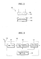
- FIG. 2 is a sectional view showing an example of connecting portion 300 .
- the connecting portion 300 includes a first fixing portion 320 and a second fixing potion 340 , and a first transmitting terminal 360 and a second transmitting terminal 380 .
- the first fixing portion 320 and the first transmitting terminal 360 are provided on part of a casing of the recording system 200 .
- the second fixing portion 340 and the second transmitting terminal 380 are provided on part of a casing of the recording system 200 .
- the second fixing portion 340 and the second transmitting terminal 380 are constructed based on the common specification so as to permit mounting of necessary accessories for shooting.
- the first and the second fixing portions 320 and 340 are formed to have a structure that allows separable connection.
- the first and the second transmitting terminals 360 and 380 are connected with each other by the first and the second fixing portions 320 and 340 , thereby receiving position information from the position information outputting apparatus 100 and transmitting the received information to the recording system 200 . Accordingly, the operator no longer experiences an inconvenience of having to connect the position information outputting apparatus 100 to the computer to check the position of the object.
- FIG. 3 is a block diagram showing an example of the calculator 140 of FIG. 1.
- the calculator 140 includes an amplifier 142 , a high frequency signal processor 144 , a synchronization amplifier 146 and a position calculator 148 .
- the amplifier 142 analogue-amplifies the position calculation data received at an antenna 120 , that is, at the receiver 120 that receives the data from the satellites for position calculation.
- the synchronization amplifier 146 provides the synchronization signal of the data used for position calculation that is amplified at the amplifier 142 .
- the high frequency signal processor 144 high-frequency signal processes the data for position calculation that is amplified at the amplifier 142 , based on the synchronization signal provided by the synchronization amplifier 146 .
- the position calculator 148 calculates the current position of the object based on the synchronization signal provided by the synchronization amplifier 146 and the data for position calculation output from the high frequency signal processor 144 .
- FIG. 4 is a block diagram showing an example of the transmitter 160 of FIG. 1.
- the transmitter 160 includes an output controller 162 , a storage 164 , a display element 166 and an interface 168 .
- the output controller 162 outputs the position information calculated from the position calculator 148 to a corresponding part via a data transfer bus.
- the storage 164 stores the position information output from the output controller 162 .
- the display element 166 displays the position information output from the output controller 162 in a display device such as a liquid crystal display (LCD).
- the interface 168 outputs the position information output from the output controller 162 to external devices such as a computer and so on.
- the output controller 162 transmits the position information calculated at the position calculator 148 when the position information outputting apparatus 100 is connected to the recording system 200 through the connecting portion 300 .
- the output controller 162 stores the position information calculated at the position calculator 148 in the storage 164 when the position information outputting apparatus 100 is not connected with the recording system 200 .
- FIG. 5 is a block diagram showing an exemplary of the shooting unit 220 of FIG. 1 in greater detail.
- the shooting unit 220 includes a lens 221 , a charge coupled device (CCD) 223 , a first image processor 225 , an image controller 229 , and a compression processor 227 .
- the lens 221 is used for capturing images of the object.
- the CCD 223 accumulates the images of the object and transmits the accumulated images.
- the first image processor 225 converts the image provided by the CCD 223 into a signal suitable for recording.
- the image controller 229 controls the signal conversion of the first image processor 225 .
- the compression processor 227 compresses the images converted at the first image processor 225 into a predetermined recording format of the recording system 200 .
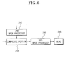
- FIG. 6 is a block diagram showing an example of the recording unit 240 of FIG. 1 in greater detail.
- the recording unit 240 includes a second image processor 242 , a combining portion 244 , a third image processor 246 and a head 248 .
- the second image processor 242 converts the position information provided through the connecting portion 300 into a format suitable for recording on the recording medium.
- the combining portion 244 combines the compressed image output from the compression processor 227 with the position information into a single signal.
- the third image processor 246 converts the combined signal of image and position information from the combining portion 244 into a format suitable for recording on the recording medium.
- the head 248 records the signal converted at the third image processor 246 on the recording medium.
- a magnetic tape is used as the recording medium by way of an example.
- the image of the object and the position information are matched with each other before being recorded on the recording medium.
- the position information outputting apparatus 100 since the position information outputting apparatus 100 operates on the independent power supply separate from the recording system 200 , the position information outputting apparatus 100 can be separated from the digital recording/reproducing device. Accordingly, in the case of obtaining the position information of the current position of the object without recording the images of the object, since the power is not supplied to the recording system 200 , power consumption can be reduced.
- the present invention it is possible to estimate the position of the object even under the unstable reception, by separately placing the position information outputting apparatus 100 in a place where reception is better.
- the position information outputting apparatus 100 receives the data for position calculation from the satellites in a more stable manner. Since the position information outputting apparatus 100 can be separately used, the position information outputting apparatus 100 can store the calculated position information periodically, and thus it is possible to predict the position of the object even when the position information cannot be acquired, by using such stored position information.
Abstract
A removable apparatus for use in a digital recording/reproducing device, for outputting position information, and a digital recording/reproducing device having the same. The removable apparatus has a global positioning system (GPS) having a receiver for externally receiving data for position calculation, a calculator for calculating the position information using the data for position calculation, a connecting portion comprising a fixing portion removably secured to an external device and a transmitting terminal for transmitting the position information to the external device, and a transmitter for transmitting the position information calculated by the calculator to the external device connected to the fixing portion through the transmitting terminal. Preferably, the GPS terminal further includes a power supply for supplying a driving power to the receiver, the calculator and the transmitter. Accordingly, by matching the image of the object with the position information of the image, and then recording the same on the recording medium, it becomes easier to check the position information of the image being displayed during the reproducing of the recording medium.
Description
- This application claims benefit under 35 U.S.C. §119 from Korean Patent Application No. 2002-20536, filed on Apr. 16, 2002, the entire content of which is incorporated herein by reference.
- 1. Field of the Invention
- The present invention generally relates to a digital recording/reproducing device, and more particularly, to a digital recording/reproducing device capable of recording information pertaining to a position of an object of which an image is being recorded by the digital recording/reproducing device.
- 2. Description of the Related Art
- Generally, a digital recording/reproducing device has the function of a video camera that captures an image of an object, and of a video recorder that records the image of the object. An operator of such a digital recording/reproducing device can take images of an object and record the images of the object on a recording medium, such as a magnetic tape and a memory stick. Furthermore, the operator can check the images of the object by reproducing the image from the recording medium. Such a reproduced image is typically displayed through a view finder.
- The advantage of a digital recording/reproducing device is that it is a portable image capturing device that is easy to use and can capture an image of a desired object in any place, namely, outside, at a concert, and so on. However, the digital recording/reproducing device has a disadvantage in that the operator cannot check the position of the object when displaying the reproduced image from the recording medium.
- In order to overcome the above-mentioned disadvantage, conventionally, a global positioning system (GPS) has been used. One method that uses GPS is to find the position of the object by calculating the position information through the portable GPS terminal during the time that the digital recording/reproducing device is capturing an image of the object, and then matching that time with the time indicated by a portable GPS terminal. Another method is to record the image of the object together with the position information calculated from a built-in GPS terminal while the image is being captured.
- According to the first method mentioned above, the operator experiences an inconvenience of having to carry the portable GPS terminal for every shooting of the object. Additionally, because the portable GPS terminal requires a memory of enough storage capacity to store the position information calculated by the portable GPS terminal, the unit price of the portable GPS terminal is quite expensive. The operator also experiences an inconvenience because he or she needs to check the respective time on the screen by connecting to a personal computer in order to match the time of the position information stored in the portable GPS terminal and the time of the image information stored in the recording medium of the digital recording/reproducing device.
- According to the second method mentioned above that uses the built-in GPS terminal, a predetermined time elapses from when the power is supplied to the GPS terminal until the position measurement is made from which the position of the object is calculated. Accordingly, from the time power is supplied to a certain point in time, the position information is not properly recorded on the recording medium. Further, if the image shooting is performed in places where there is unstable reception of the signals from the GPS satellites, for example, if the shooting is performed in the skyscraper where the satellite signal reception is usually blocked, the position information is not calculated, and thus the position information of the image cannot be recorded on the recording medium.
- Accordingly, it is an object of the present invention to provide a GPS terminal with which a user of a digital recording/reproducing device does not experience the inconvenience of having to carry a portable GPS terminal for every shooting in order to check the position information of an object.
- Another object of the present invention is to provide a GPS terminal capable of solving the problem in which an error is generated in the position information due to a certain amount of time lapse from when the power is supplied until the position measurement is taken.
- The above objects, as well as other objects, are substantially accomplished by a global positioning system (GPS) terminal according to an embodiment of the present invention, which includes a receiver for receiving data for position calculation transmitted from a satellite; a calculator for calculating the position information using the data for position calculation; a connecting portion comprising a fixing portion for removably connecting to an external device, and a transmitting terminal for transmitting the position information to the external device; and a transmitter for transmitting the position information calculated by the calculator to the external device connected to the fixing portion through the transmitting terminal. Preferably, further provided is a power supply for supplying power to the receiver, the calculator and the transmitter.
- The above objects are also substantially accomplished by a digital recording/reproducing device according to an embodiment of the present invention, including an image capturing unit for capturing an image of an object; a recording unit for recording an image of the object taken by the image capturing unit on a recording medium; a GPS terminal for externally receiving a data for position calculation, and calculating the position information using the data for position calculation as received; and a connecting portion provided on a part of a casing that houses the image capturing unit and the recording unit therein, the connecting portion comprising a fixing portion for removably connecting the position information outputting apparatus with the casing, and a transmitting terminal for transmitting the position information output from the position information outputting apparatus to the recording unit.
- Preferably, when the position information is received through the transmitting terminal, the recording unit records the image of the object on the recording medium together with the position information.
- The position information outputting apparatus includes a receiver for externally receiving the data for position calculation; a calculator for calculating the position information using the data for position calculation; and a transmitter for transmitting the position information calculated at the calculator to the recording unit through the transmitting terminal. The position information outputting apparatus further includes a power supply for supplying a driving power to the receiver, the calculator and the transmitter. The position information outputting apparatus is, for example, a GPS terminal.
- According to an object of the present invention, because the images of the object are recorded in association with the calculated position information at the time the image of the object is being captured, it is easier to check the position information of the object during the reproducing of the recorded images.
- The above and other objects, features and other advantages of the present invention will be more clearly understood from the following detailed description taken in conjunction with the accompanying drawings, in which:
- FIG. 1 is a block diagram showing an example of a digital recording/reproducing device according to an embodiment of the present invention;
- FIG. 2 is a sectional view showing an example of the connecting unit of FIG. 1;
- FIG. 3 is a block diagram showing an example of the calculating unit of FIG. 1;
- FIG. 4 is a block diagram showing an example of the transmitting unit of FIG. 1;
- FIG. 5 is a block diagram showing an example of the shooting unit of FIG. 1 in greater detail; and
- FIG. 6 is a block diagram showing a recording unit of FIG. 1 in greater detail.
- Reference will now be made in detail to certain embodiments of the present invention.
- FIG. 1 is a block diagram showing an example of a digital recording/reproducing device according to an embodiment of the present invention, which is capable of recording position information of an object whose image is being captured. Hereinafter, the digital recording/reproducing device will be described.
- As shown in FIG. 1, the digital recording/reproducing device includes a position
information outputting apparatus 100 for calculating and outputting position information, arecording system 200 for shooting and taking images of an object and recording the taken images in association with the position information output from the positioninformation outputting apparatus 100, and a connectingportion 300 for separably connecting the positioninformation outputting apparatus 100 with therecording system 200 and for transmitting the position information from the positioninformation outputting apparatus 100 to therecording system 200. Accordingly, therecording system 200 is capable of recording the images of the object together with the position information received through the connectingportion 300. In reproducing of the recording medium, the operator can check the position information of the image on the recording medium. Throughout the description of the embodiments, a GPS terminal will be described as the positioninformation outputting apparatus 100 by way of example. - The position
information outputting apparatus 100 includes areceiver 120, acalculator 140, atransmitter 160 and apower supply 180. Thereceiver 120 receives the data to be used for position calculation from the satellite. Thecalculator 140 calculates the position information corresponding to the current position of the object based on the data for position calculation received at thereceiver 120. Thetransmitter 160 transmits the position information calculated at thecalculator 140 to therecording system 200 through the connectingportion 300. Thepower supply 180 supplies independent power to the positioninformation outputting apparatus 100 irrespective of whether or not the positioninformation outputting apparatus 100 is connected to therecording system 200 through the connectingportion 300. That is, thepower supply 180 supplies independent power to thereceiver 120, to thecalculator 140 and to thetransmitter 160, respectively. - Meanwhile, the
recording system 200 includes an image capturing device, referred to as ashooting unit 220, and arecording unit 240. Theshooting unit 220 takes the images of the object, and converts the images into a format suitable for recording. Therecording unit 240 combines the image output from theshooting unit 220 with the position information received through the connectingportion 300 and records the combined data on the recording medium. - FIG. 2 is a sectional view showing an example of connecting
portion 300. Referring to FIG. 2, the connectingportion 300 includes afirst fixing portion 320 and asecond fixing potion 340, and a first transmittingterminal 360 and a second transmittingterminal 380. Thefirst fixing portion 320 and the first transmittingterminal 360 are provided on part of a casing of therecording system 200. Further, thesecond fixing portion 340 and the secondtransmitting terminal 380 are provided on part of a casing of therecording system 200. Preferably, thesecond fixing portion 340 and the second transmittingterminal 380 are constructed based on the common specification so as to permit mounting of necessary accessories for shooting. - Accordingly, the first and the
second fixing portions terminals second fixing portions information outputting apparatus 100 and transmitting the received information to therecording system 200. Accordingly, the operator no longer experiences an inconvenience of having to connect the positioninformation outputting apparatus 100 to the computer to check the position of the object. - FIG. 3 is a block diagram showing an example of the
calculator 140 of FIG. 1. Thecalculator 140 includes anamplifier 142, a highfrequency signal processor 144, asynchronization amplifier 146 and aposition calculator 148. Theamplifier 142 analogue-amplifies the position calculation data received at anantenna 120, that is, at thereceiver 120 that receives the data from the satellites for position calculation. Thesynchronization amplifier 146 provides the synchronization signal of the data used for position calculation that is amplified at theamplifier 142. The highfrequency signal processor 144 high-frequency signal processes the data for position calculation that is amplified at theamplifier 142, based on the synchronization signal provided by thesynchronization amplifier 146. Theposition calculator 148 calculates the current position of the object based on the synchronization signal provided by thesynchronization amplifier 146 and the data for position calculation output from the highfrequency signal processor 144. - FIG. 4 is a block diagram showing an example of the
transmitter 160 of FIG. 1. As shown, thetransmitter 160 includes anoutput controller 162, astorage 164, adisplay element 166 and aninterface 168. Theoutput controller 162 outputs the position information calculated from theposition calculator 148 to a corresponding part via a data transfer bus. Thestorage 164 stores the position information output from theoutput controller 162. Thedisplay element 166 displays the position information output from theoutput controller 162 in a display device such as a liquid crystal display (LCD). Theinterface 168 outputs the position information output from theoutput controller 162 to external devices such as a computer and so on. Preferably, theoutput controller 162 transmits the position information calculated at theposition calculator 148 when the positioninformation outputting apparatus 100 is connected to therecording system 200 through the connectingportion 300. Theoutput controller 162 stores the position information calculated at theposition calculator 148 in thestorage 164 when the positioninformation outputting apparatus 100 is not connected with therecording system 200. - FIG. 5 is a block diagram showing an exemplary of the
shooting unit 220 of FIG. 1 in greater detail. Theshooting unit 220 includes alens 221, a charge coupled device (CCD) 223, afirst image processor 225, animage controller 229, and acompression processor 227. Thelens 221 is used for capturing images of the object. TheCCD 223 accumulates the images of the object and transmits the accumulated images. Thefirst image processor 225 converts the image provided by theCCD 223 into a signal suitable for recording. Theimage controller 229 controls the signal conversion of thefirst image processor 225. Thecompression processor 227 compresses the images converted at thefirst image processor 225 into a predetermined recording format of therecording system 200. - FIG. 6 is a block diagram showing an example of the
recording unit 240 of FIG. 1 in greater detail. Therecording unit 240 includes asecond image processor 242, a combiningportion 244, athird image processor 246 and ahead 248. Thesecond image processor 242 converts the position information provided through the connectingportion 300 into a format suitable for recording on the recording medium. The combiningportion 244 combines the compressed image output from thecompression processor 227 with the position information into a single signal. Thethird image processor 246 converts the combined signal of image and position information from the combiningportion 244 into a format suitable for recording on the recording medium. Thehead 248 records the signal converted at thethird image processor 246 on the recording medium. As described below, a magnetic tape is used as the recording medium by way of an example. - According to an embodiment of the present invention, the image of the object and the position information are matched with each other before being recorded on the recording medium. As a result, it is easy for the operator to check the position information of the displayed images during reproducing of the recording medium.
- Further, since the position
information outputting apparatus 100 operates on the independent power supply separate from therecording system 200, the positioninformation outputting apparatus 100 can be separated from the digital recording/reproducing device. Accordingly, in the case of obtaining the position information of the current position of the object without recording the images of the object, since the power is not supplied to therecording system 200, power consumption can be reduced. - According to an embodiment the present invention, it is possible to estimate the position of the object even under the unstable reception, by separately placing the position
information outputting apparatus 100 in a place where reception is better. Thus, the positioninformation outputting apparatus 100 receives the data for position calculation from the satellites in a more stable manner. Since the positioninformation outputting apparatus 100 can be separately used, the positioninformation outputting apparatus 100 can store the calculated position information periodically, and thus it is possible to predict the position of the object even when the position information cannot be acquired, by using such stored position information. - Although certain embodiments of the present invention have been disclosed for illustrative purposes, those skilled in the art will appreciate that various modifications, additions and substitutions can be made without departing from the scope and spirit of the invention as disclosed in the accompanying claims.
Claims (12)
1. A position determining device, adapted for use with an image recording device, the position determining device comprising:
a receiver, adapted to receive data for position calculation;
a calculator, adapted to calculate position information based on said data for position calculation;
a connecting portion comprising a fixing portion, adapted to removably connect to the image recording device, and a transmitting terminal adapted to provide said position information to the image recording device; and
a transmitter, adapted to transmit said position information calculated by said calculator to the image recording device connected to said fixing portion via said transmitting terminal.
2. A position determining device as claimed in claim 1 , further comprising:
a power supply, adapted to supplying power to said receiver, said calculator and said transmitter.
3. A position determining device as claimed in claim 1 , wherein said receiver is adapted to receive said data from a satellite.
4. A position determining device as claimed in claim 1 , wherein:
said fixing portion comprises first and second fixing portions, adapted to couple to each other; and
said transmitting terminal comprises first and second transmitting terminals, adapted to couple to each other when said first and second fixing portions are coupled to each other.
5. A position determining device as claimed in claim 1 , wherein said calculator comprises:
an amplifier, adapted to amplify said data received by said receiver and output an amplified signal;
a synchronization device, adapted to output a synchronization signal;
a signal processor, adapted to process said data based on said synchronization signal and output a processed signal; and
a position calculator, adapted to calculate said position information based on said processed signal.
6. A position determining device as claimed in claim 1 , wherein:
the image recording device includes a video recording/reproducing device; and
said transmitting terminal is adapted to provide said position information to the video recording/reproducing device.
7. A digital recording/reproducing device, comprising:
an image capturing unit, adapted to capture an image of an object;
a recording unit, adapted to record said image of the object taken by said image capturing unit on a recording medium;
a positing determining device, adapted to receive data for position calculation, and to calculate position information using said data; and
a connecting portion, comprising a fixing portion adapted to removably connect said position determining device to a casing that houses at least one of the image capturing unit and the recording unit therein, and a transmitting terminal adapted to transmit said position information output from said position determining device to said recording unit.
8. A digital recording/reproducing device as claimed in claim 7 , wherein:
said connecting portion is provided on a portion of said casing that houses said image capturing unit and said recording unit therein.
9. A digital recording/reproducing device as claimed in claim 7 , wherein:
said recording unit is further adapted to record said image of the object on said recording medium together with said position information when said recording unit receives said position information via said transmitting terminal.
10. A digital recording/reproducing device as claimed in claim 7 , wherein said position determining device comprises:
a receiver, adapted to receive said data for position calculation;
a calculator, adapted to calculate said position information using said data; and
a transmitter, adapted to transmit said position information calculated by said calculator to said recording unit via said transmitting terminal.
11. A digital recording/reproducing device as claimed in claim 10 , wherein said position determining device comprises:
a power supply, adapted to supply driving power to said receiver, said calculator and said transmitter.
12. A digital recording/reproducing device as claimed in claim 7 , wherein said position determining device comprises:
a global positioning system (GPS) terminal.
Applications Claiming Priority (2)
| Application Number | Priority Date | Filing Date | Title |
|---|---|---|---|
| KR2002-20536 | 2002-04-16 | ||
| KR1020020020536A KR100777458B1 (en) | 2002-04-16 | 2002-04-16 | Apparatus for outputting location information capable of attaching to an image recording apparatus detachably, and an image recording apparatus having the same |
Publications (1)
| Publication Number | Publication Date |
|---|---|
| US20030193575A1 true US20030193575A1 (en) | 2003-10-16 |
Family
ID=28786956
Family Applications (1)
| Application Number | Title | Priority Date | Filing Date |
|---|---|---|---|
| US10/409,582 Abandoned US20030193575A1 (en) | 2002-04-16 | 2003-04-09 | Removable apparatus for use in a digital recording/reproducing device for outputing position information, and a digital recording/reproducing device having the same |
Country Status (2)
| Country | Link |
|---|---|
| US (1) | US20030193575A1 (en) |
| KR (1) | KR100777458B1 (en) |
Cited By (3)
| Publication number | Priority date | Publication date | Assignee | Title |
|---|---|---|---|---|
| EP1648162A1 (en) * | 2003-04-14 | 2006-04-19 | Tai-Her Yang | Combined or standalone hand-held A/V camera system |
| US20080019564A1 (en) * | 2004-06-29 | 2008-01-24 | Sony Corporation | Information Processing Device And Method, Program, And Information Processing System |
| US20130147984A1 (en) * | 2011-12-08 | 2013-06-13 | Canon Kabushiki Kaisha | Image pickup apparatus, method for controlling the same, and program for obtaining position information and direction information |
Families Citing this family (2)
| Publication number | Priority date | Publication date | Assignee | Title |
|---|---|---|---|---|
| KR101452711B1 (en) * | 2008-06-05 | 2014-10-21 | 삼성전자주식회사 | Digital camera and control method thereof |
| KR101028492B1 (en) * | 2009-05-14 | 2011-04-11 | 인하대학교 산학협력단 | A camera flash module with GIS data recording apparatus |
Citations (14)
| Publication number | Priority date | Publication date | Assignee | Title |
|---|---|---|---|---|
| US5267042A (en) * | 1991-01-11 | 1993-11-30 | Pioneer Electronic Corporation | Image pickup device for automatically recording the location where an image is recorded |
| US5488558A (en) * | 1993-10-20 | 1996-01-30 | Daishin Instrument Co., Ltd. | Handy computer with built-in digital camera and spot state recording method using the same |
| US5768640A (en) * | 1995-10-27 | 1998-06-16 | Konica Corporation | Camera having an information recording function |
| US5893037A (en) * | 1994-12-09 | 1999-04-06 | Eastman Kodak Company | Combined electronic/silver-halide image capture system with cellular transmission capability |
| US5893767A (en) * | 1997-05-30 | 1999-04-13 | The Whitaker Corporation | Electrical connector having a switch |
| US5913078A (en) * | 1994-11-01 | 1999-06-15 | Konica Corporation | Camera utilizing a satellite positioning system |
| US6005936A (en) * | 1996-11-28 | 1999-12-21 | Ibm | System for embedding authentication information into an image and an image alteration detecting system |
| US6222985B1 (en) * | 1997-01-27 | 2001-04-24 | Fuji Photo Film Co., Ltd. | Camera which records positional data of GPS unit |
| US6525768B2 (en) * | 1998-10-21 | 2003-02-25 | American Calcar, Inc. | Positional camera and GPS data interchange device |
| US6741864B2 (en) * | 2000-02-21 | 2004-05-25 | Hewlett-Packard Development Company, L.P. | Associating image and location data |
| US6785814B1 (en) * | 1998-07-28 | 2004-08-31 | Fuji Photo Film Co., Ltd | Information embedding method and apparatus |
| US20050046706A1 (en) * | 2003-08-28 | 2005-03-03 | Robert Sesek | Image data capture method and apparatus |
| US6995792B1 (en) * | 1999-09-30 | 2006-02-07 | Casio Computer Co., Ltd. | Camera with positioning capability |
| US7016899B1 (en) * | 2000-09-21 | 2006-03-21 | Lenovo (Singapore) Pte. Ltd. | Camera device, methods and program products for location and environmental stamping of images, communications and other applications |
Family Cites Families (2)
| Publication number | Priority date | Publication date | Assignee | Title |
|---|---|---|---|---|
| JP3743251B2 (en) * | 2000-03-15 | 2006-02-08 | 松下電工株式会社 | Power supply |
| JP2001285785A (en) * | 2001-01-26 | 2001-10-12 | Konica Corp | Image recorder |
-
2002
- 2002-04-16 KR KR1020020020536A patent/KR100777458B1/en not_active IP Right Cessation
-
2003
- 2003-04-09 US US10/409,582 patent/US20030193575A1/en not_active Abandoned
Patent Citations (14)
| Publication number | Priority date | Publication date | Assignee | Title |
|---|---|---|---|---|
| US5267042A (en) * | 1991-01-11 | 1993-11-30 | Pioneer Electronic Corporation | Image pickup device for automatically recording the location where an image is recorded |
| US5488558A (en) * | 1993-10-20 | 1996-01-30 | Daishin Instrument Co., Ltd. | Handy computer with built-in digital camera and spot state recording method using the same |
| US5913078A (en) * | 1994-11-01 | 1999-06-15 | Konica Corporation | Camera utilizing a satellite positioning system |
| US5893037A (en) * | 1994-12-09 | 1999-04-06 | Eastman Kodak Company | Combined electronic/silver-halide image capture system with cellular transmission capability |
| US5768640A (en) * | 1995-10-27 | 1998-06-16 | Konica Corporation | Camera having an information recording function |
| US6005936A (en) * | 1996-11-28 | 1999-12-21 | Ibm | System for embedding authentication information into an image and an image alteration detecting system |
| US6222985B1 (en) * | 1997-01-27 | 2001-04-24 | Fuji Photo Film Co., Ltd. | Camera which records positional data of GPS unit |
| US5893767A (en) * | 1997-05-30 | 1999-04-13 | The Whitaker Corporation | Electrical connector having a switch |
| US6785814B1 (en) * | 1998-07-28 | 2004-08-31 | Fuji Photo Film Co., Ltd | Information embedding method and apparatus |
| US6525768B2 (en) * | 1998-10-21 | 2003-02-25 | American Calcar, Inc. | Positional camera and GPS data interchange device |
| US6995792B1 (en) * | 1999-09-30 | 2006-02-07 | Casio Computer Co., Ltd. | Camera with positioning capability |
| US6741864B2 (en) * | 2000-02-21 | 2004-05-25 | Hewlett-Packard Development Company, L.P. | Associating image and location data |
| US7016899B1 (en) * | 2000-09-21 | 2006-03-21 | Lenovo (Singapore) Pte. Ltd. | Camera device, methods and program products for location and environmental stamping of images, communications and other applications |
| US20050046706A1 (en) * | 2003-08-28 | 2005-03-03 | Robert Sesek | Image data capture method and apparatus |
Cited By (7)
| Publication number | Priority date | Publication date | Assignee | Title |
|---|---|---|---|---|
| EP1648162A1 (en) * | 2003-04-14 | 2006-04-19 | Tai-Her Yang | Combined or standalone hand-held A/V camera system |
| US20080019564A1 (en) * | 2004-06-29 | 2008-01-24 | Sony Corporation | Information Processing Device And Method, Program, And Information Processing System |
| US7739033B2 (en) * | 2004-06-29 | 2010-06-15 | Sony Corporation | Information processing device and method, program, and information processing system |
| US20130147984A1 (en) * | 2011-12-08 | 2013-06-13 | Canon Kabushiki Kaisha | Image pickup apparatus, method for controlling the same, and program for obtaining position information and direction information |
| US9277118B2 (en) * | 2011-12-08 | 2016-03-01 | Canon Kabushiki Kaisha | Image pickup apparatus, method for controlling the same, and program for obtaining position information and direction information |
| US20160155224A1 (en) * | 2011-12-08 | 2016-06-02 | Canon Kabushiki Kaisha | Image pickup apparatus, method for controlling the same, and program for obtaining position information and direction information |
| US9667826B2 (en) * | 2011-12-08 | 2017-05-30 | Canon Kabushiki Kaisha | Image pickup apparatus, method for controlling the same, and program for obtaining position information and direction information |
Also Published As
| Publication number | Publication date |
|---|---|
| KR20030082032A (en) | 2003-10-22 |
| KR100777458B1 (en) | 2007-11-21 |
Similar Documents
| Publication | Publication Date | Title |
|---|---|---|
| US7535415B2 (en) | Image recording apparatus capable of recording position and direction information of object of shooting | |
| US7386174B2 (en) | Image transmission apparatus and method therefor | |
| US20040189813A1 (en) | System and method of photography using digital camera | |
| JP3513084B2 (en) | Information processing system, information equipment and information processing method | |
| KR100397810B1 (en) | Camera, camera system, information recording system, timepiece, and link system and link method for camera and timepiece equipment | |
| US8170411B2 (en) | System and method for inputting position information in captured image | |
| US20120154609A1 (en) | Image recording device, image recording method, and program | |
| US4897732A (en) | Electronic camera | |
| US20030193575A1 (en) | Removable apparatus for use in a digital recording/reproducing device for outputing position information, and a digital recording/reproducing device having the same | |
| JP2005295030A (en) | Map information display system | |
| JP5482169B2 (en) | Digital camera, message display method, and program | |
| JPH0927937A (en) | Recorder for name of image pickup point | |
| KR100806395B1 (en) | Image recording apparatus capable of recoding image and position information | |
| JPH08154228A (en) | Camcorder | |
| JP3997796B2 (en) | Photo composition system, image supply device, digital camera | |
| JP3019771B2 (en) | Recording device | |
| JP2000196987A (en) | Portable information terminal | |
| KR100933289B1 (en) | Photographing apparatus for supplying power to CPU unit only while recording video signal and power control method thereof | |
| JP2005354419A (en) | Video camera | |
| JP3158672B2 (en) | Recording device and playback device | |
| JP4004909B2 (en) | Navigation system and control method thereof | |
| JP2005124016A (en) | Transmitter and receiver | |
| JP2006229276A (en) | Communications device, imaging apparatus, and information recording/reproducing system | |
| JP2009088985A (en) | Digital camera and communication control method thereof, and image processing system | |
| JPH10308917A (en) | Recording/reproducing device with position information recording function |
Legal Events
| Date | Code | Title | Description |
|---|---|---|---|
| AS | Assignment |
Owner name: SAMSUNG ELECTRONICS CO., LTD., KOREA, REPUBLIC OF Free format text: ASSIGNMENT OF ASSIGNORS INTEREST;ASSIGNOR:YOSHIOKA, HARUYUKI;REEL/FRAME:013962/0880 Effective date: 20030403 |
|
| STCB | Information on status: application discontinuation |
Free format text: ABANDONED -- FAILURE TO RESPOND TO AN OFFICE ACTION |