US20030194601A1 - Header for rechargeable lithium batteries - Google Patents
Header for rechargeable lithium batteries Download PDFInfo
- Publication number
- US20030194601A1 US20030194601A1 US10/408,935 US40893503A US2003194601A1 US 20030194601 A1 US20030194601 A1 US 20030194601A1 US 40893503 A US40893503 A US 40893503A US 2003194601 A1 US2003194601 A1 US 2003194601A1
- Authority
- US
- United States
- Prior art keywords
- battery
- header
- rupture disc
- weld plate
- rechargeable lithium
- Prior art date
- Legal status (The legal status is an assumption and is not a legal conclusion. Google has not performed a legal analysis and makes no representation as to the accuracy of the status listed.)
- Granted
Links
Images


Classifications
-
- H—ELECTRICITY
- H01—ELECTRIC ELEMENTS
- H01M—PROCESSES OR MEANS, e.g. BATTERIES, FOR THE DIRECT CONVERSION OF CHEMICAL ENERGY INTO ELECTRICAL ENERGY
- H01M50/00—Constructional details or processes of manufacture of the non-active parts of electrochemical cells other than fuel cells, e.g. hybrid cells
- H01M50/30—Arrangements for facilitating escape of gases
- H01M50/342—Non-re-sealable arrangements
- H01M50/3425—Non-re-sealable arrangements in the form of rupturable membranes or weakened parts, e.g. pierced with the aid of a sharp member
-
- H—ELECTRICITY
- H01—ELECTRIC ELEMENTS
- H01M—PROCESSES OR MEANS, e.g. BATTERIES, FOR THE DIRECT CONVERSION OF CHEMICAL ENERGY INTO ELECTRICAL ENERGY
- H01M50/00—Constructional details or processes of manufacture of the non-active parts of electrochemical cells other than fuel cells, e.g. hybrid cells
- H01M50/50—Current conducting connections for cells or batteries
- H01M50/572—Means for preventing undesired use or discharge
- H01M50/574—Devices or arrangements for the interruption of current
- H01M50/578—Devices or arrangements for the interruption of current in response to pressure
-
- H—ELECTRICITY
- H01—ELECTRIC ELEMENTS
- H01M—PROCESSES OR MEANS, e.g. BATTERIES, FOR THE DIRECT CONVERSION OF CHEMICAL ENERGY INTO ELECTRICAL ENERGY
- H01M10/00—Secondary cells; Manufacture thereof
- H01M10/05—Accumulators with non-aqueous electrolyte
- H01M10/052—Li-accumulators
- H01M10/0525—Rocking-chair batteries, i.e. batteries with lithium insertion or intercalation in both electrodes; Lithium-ion batteries
-
- Y—GENERAL TAGGING OF NEW TECHNOLOGICAL DEVELOPMENTS; GENERAL TAGGING OF CROSS-SECTIONAL TECHNOLOGIES SPANNING OVER SEVERAL SECTIONS OF THE IPC; TECHNICAL SUBJECTS COVERED BY FORMER USPC CROSS-REFERENCE ART COLLECTIONS [XRACs] AND DIGESTS
- Y02—TECHNOLOGIES OR APPLICATIONS FOR MITIGATION OR ADAPTATION AGAINST CLIMATE CHANGE
- Y02E—REDUCTION OF GREENHOUSE GAS [GHG] EMISSIONS, RELATED TO ENERGY GENERATION, TRANSMISSION OR DISTRIBUTION
- Y02E60/00—Enabling technologies; Technologies with a potential or indirect contribution to GHG emissions mitigation
- Y02E60/10—Energy storage using batteries
Definitions
- This invention pertains to an improved header for non-aqueous lithium rechargeable batteries.
- the header incorporates a riveted disconnect mechanism. It is particularly useful for high power applications as the current distribution through the improved header is more efficient and the electrical impedance of the battery is significantly reduced when compared to a conventional header.
- Rechargeable lithium-ion batteries are the preferred rechargeable power source for many consumer electronics applications. These batteries have the greatest energy density (Wh/L) of presently available conventional rechargeable systems (ie. NiCd, NiMH, or lead acid batteries). Additionally, because of the higher operating voltage of lithium ion batteries fewer cells need to be connected in series than for these other rechargeable systems. Consequently lithium ion batteries are increasingly attractive for high power applications such as electric bicycles, portable power tools and hybrid electric vehicles. Lithium ion batteries use two different insertion compounds for the active cathode and anode materials. Lithium ion batteries based on the LiCoO 2 /graphite system are now commercially available.
- lithium transition metal oxide compounds are suitable for use as the cathode material, including LiNiO 2 and LiMn 2 O 4 .
- carbonaceous compounds is suitable for use as the anode material, including coke and non-graphetizing hard carbon.
- the aforementioned products employ non-aqueous electrolytes comprising LiBF 4 or LiPF 6 salts and solvent mixtures of ethylene carbonate, propylene carbonate, diethyl carbonate, ethyl methyl carbonate, and the like. Again, numerous options for the choice of salts and/or solvents in such batteries are known to exist in the art.
- Lithium ion batteries can be sensitive to certain types of abuse, particularly overcharge abuse wherein the normal operating voltage is exceeded during recharge. During overcharge, excessive lithium is extracted from the cathode with a corresponding excessive insertion or even plating of lithium at the anode. This can make both electrodes less stable thermally. Overcharging also results in heating of the battery since much of the input energy is dissipated rather than stored. The decrease in thermal stability combined with battery heating can lead to thermal runaway and fire on overcharge. Many manufacturers have incorporated safety devices to provide protection against overcharge abuse. For instance, as described in U.S. Pat. No. 4,943,497 and Canadian Patent No. 2,099,657 respectively, the present products of Sony and E-One Moli Energy (Canada) Limited incorporate internal disconnect devices which activate when the internal pressure of the battery exceeds a predetermined value during overcharge abuse.
- a jelly roll 4 is created by spirally winding a cathode foil 1 , an anode foil 2 , and two microporous polyolefin sheets 3 that act as separators.
- the jelly roll 4 is inserted into a conventional battery can 10 .
- a header 11 and gasket 12 are used to seal the battery 15 .
- the header includes an internal electrical disconnect device similar to that shown in the aforementioned Canadian Patent No. 2,099,657 and additional safety devices if desired. Often, a safety vent is incorporated that ruptures if excessive pressure builds up in the battery. Also, a positive thermal coefficient device (PTC) may be incorporated into the header to limit the short circuit current capability of the battery.
- PTC positive thermal coefficient device
- the external surface of the header 11 is used as the positive terminal, while the external surface of the can 10 serves as the negative terminal.
- cathode tab 6 and anode tab 7 connections are made to connect the internal electrodes to the external terminals.
- Appropriate insulating pieces 8 and 9 may be inserted to prevent the possibility of internal shorting.
- electrolyte 5 is added to fill the porous spaces in the jelly roll 4 .
- FIG. 2 a shows details of a similar header as depicted in FIG. 1.
- the assembly comprises the following sequence: a cap 1 with vent holes, two nickel rings 2 , a rupture disc 3 , a locating insulator 4 , a weld plate 5 that snap fits into a polypropylene gasket 6 .
- the rupture disc 3 is laser welded to the centre of the weld plate 5 .
- the cathode tab is in turn laser welded to the bottom of the weld plate 5 . Therefore, all the current must flow through the small contact area at the centre of the weld plate 5 making the battery hot during charging and discharging. This is undesirable for high power cells because the localized high current densities can generate heat, which is not easily dissipated from such a confined area. Moreover, it is difficult to decouple disconnect pressure from current carrying capability for conventional header design.
- the present invention is an improved header for cylindrical lithium rechargeable batteries. It is particularly useful for high power applications as the heat generated during battery cycling is dissipated more efficiently.
- the header assembly comprises a cap with tear-tabs on the vent holes, a rupture disc, an insulator disc, and an annular plate that snap fits into the polypropylene gasket. Laser welding between the rupture disc and the weld plate is eliminated. Instead, the annular weld plate is riveted to the rupture disc. The cathode tab or multiple tabs are welded off centre to the annular weld plate.
- the improvement lies in the increased current carrying capacity through the distributed contact between the annular weld plate and the rupture disc and a decrease in the electrical impedance of the battery.
- the number of parts for the header is reduced, thus making the assembly simple to manufacture in large quantities.
- the mechanism to activate the electrical disconnect is also improved.
- the conventional header disconnects by breaking the scored centre section of the rupture disc above a prescribed pressure as shown in FIG. 2 b .
- the improved header disconnects when the rupture disc is deformed as shown in FIG. 3 b .
- the pressure at which the header disconnects is controlled by the degree of crimp applied to the rupture disc 2 . Therefore, the disconnect is not easily activated by shock or vibration.
- the annular weld plate 4 is firmly held in place unless the rupture disc 2 is deformed by internal pressure.
- the scored section of the weld plate is vulnerable to breaking due to shock or vibration.
- FIG. 6 Another advantage of the invention is the addition of tear-tabs 1 located at the vent holes of the cap as shown in FIG. 6. These are projections on the lower part of the vent holes designed to catch and tear open the rupture disc if it continues to bulge due to excessive internal pressure over and above that required to activate the disconnect, allowing gas to escape and thereby preventing explosion from occurring.
- FIG. 1 depicts a cross-sectional view of an embodiment of a conventional cylindrical spiral-wound lithium battery.
- FIG. 2 a depicts a cross-sectional view of a conventional header for a cylindrical lithium battery.
- FIG. 2 b depicts a cross-sectional view of a conventional header for cylindrical lithium battery after the battery is disconnected.
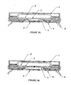
- FIG. 3 a depicts a cross-sectional view of the improved header for a cylindrical lithium battery.
- FIG. 3 b depicts a cross-sectional view of the improved header for a cylindrical lithium battery after the battery is disconnected.
- FIG. 4 depicts the current flow, I, on a cross-sectional view of a conventional header for a cylindrical lithium battery.
- FIG. 5 depicts the current flow, I, on a cross-sectional view of the improved header for a cylindrical lithium battery.
- FIG. 6 depicts the cap of the improved header
- the invention relates to an improved header design for rechargeable lithium batteries.
- the improvement lies in the increased current carrying capacity through the contact between the weld plate and the rupture disc and a decrease in the electrical impedance of the cell.
- the number of parts for the header is reduced, thus making the assembly simple for manufacturing in large quantities.
- the header design of the invention is particularly useful for high power applications.
- FIG. 1 A typical construction for a rechargeable lithium battery is depicted in the cross-sectional view of a conventional spiral-wound battery as shown in FIG. 1.
- Cathode foils are prepared by applying a mixture of a suitable powdered (about 10 micron size typically) cathode material, such as a lithiated transition metal oxide, a binder, and a conductive diluent onto a thin aluminum foil.
- a suitable powdered (about 10 micron size typically) cathode material such as a lithiated transition metal oxide, a binder, and a conductive diluent onto a thin aluminum foil.
- the application method first involves dissolving the binder in a suitable liquid carrier. Then, a slurry is prepared using this solution plus the other powdered solid components. The slurry is then coated uniformly onto the substrate foil. Afterwards, the carrier solvent is evaporated away. Often, both sides of the aluminum foil substrate are coated in this manner and subsequently the cathode foil is calendered.
- Anode foils are prepared in a like manner except that a powdered (also typically about 10 micron size) carbonaceous insertion compound is used instead of the cathode material and thin copper foil is usually used instead of aluminum.
- Anode foils are typically slightly wider than the cathode foils in order to ensure that anode foil is always opposite cathode foil.
- the jelly roll 4 is inserted into a conventional battery can 10 .
- a header 11 and gasket 12 are used to seal the battery 15 .
- the header includes an internal electrical disconnect device similar to that shown in the aforementioned Canadian Patent No. 2,099,657 and additional safety devices if desired. Often, a safety vent is incorporated that ruptures if excessive pressure builds up in the battery. Also, a positive thermal coefficient device (PTC) may be incorporated into the header to limit the short circuit current capability of the battery.
- PTC positive thermal coefficient device
- the external surface of the header 11 is used as the positive terminal, while the external surface of the can 10 serves as the negative
- cathode tab 6 and anode tab 7 connections are made to connect the internal electrodes to the external terminals.
- Appropriate insulating pieces 8 and 9 may be inserted to prevent the possibility of internal shorting.
- electrolyte 5 is added to fill the porous spaces in the jelly roll 4 .
- FIG. 2 a shows details of a similar header as depicted in FIG. 1.
- the assembly comprises the following sequence: a cap 1 with vent holes, two nickel rings 2 , a rupture disc 3 , a locating insulator 4 , a weld plate 5 that snap fits into a polypropylene gasket 6 .
- the rupture disc 3 is laser welded to the centre of the weld plate 5 .
- the cathode tab is in turn laser welded to the bottom of the weld plate 5 . Therefore, all the current must flow through the small contact area at the centre of the weld plate 5 making the battery hot during charging and discharging. This is undesirable for high power cells because the localized high current densities can generate heat, which is not easily dissipated from such a confined area.
- the conventional header structure constrains the electrical current to flow through a small area in the vicinity of the laser weld connecting the rupture disc to the weld plate. This can be graphically represented as a constriction of the lines of current flow (as indicated by the heavy line labeled I) through a tight loop of diameter d as indicated in FIG. 4. If D is the battery diameter, the ratio d/D is less than about 0.1 for conventional headers. This is undesirable for high power cells because the localized high current densities can generate heat which is not easily dissipated from such a confined area.
- FIG. 3 a shows a cross-sectional view of the improved header for a cylindrical lithium battery.
- the improved header assembly comprises the following sequence: a cap 1 with tear-tabs on the vent holes, a rupture disc 2 , a non-melting insulator disc 3 , an annular weld plate 4 that snap fits into a polypropylene gasket 5 .
- the rupture disc 2 and the annular weld plate 4 are riveted together to make a low impedance contact.
- the material of the rupture disc 2 is spread by the rivet punch supported by the ledge of the annular weld plate 4 . This is depicted in FIGS. 3 a and 3 b as the dimples on the rupture disc 2 .
- the current path length is shortened and the current density is reduced, especially at the contact area between the annular weld plate 4 and the rupture disc 2 .
- the contact area at the rivet is essentially the inside circumference of the annular weld plate 4 multiplied by the thickness of the weld plate 4 at that point, which is much larger than the cross sectional area of a laser weld spot as in the conventional headers. Consequently, the impedance is generally lower than for conventional headers.
- FIG. 3 b shows a disconnected header of the invention.
- the improved header design disconnects when the rupture disc 2 is deformed during abnormal charging situations, that is, when an internal pressure inside the battery builds up above the prescribed pressure of the rupture disc. As the rupture disc 2 bulges towards the cap 1 , the rupture disc 2 is pulled out the annular weld plate 4 and breaks the electrical connection.
- the pressure at which the header disconnects is controlled by the degree of crimp applied to the rupture disc 2 .
- the annular weld plate 4 is firmly held in place unless the rupture disc 2 is deformed by internal pressure, therefore, the disconnect is not easily activated by shock or vibration.
- the improved header structure has a distributed contact along the entire circumference of the annular weld plate so that the current flow is spread over a relatively large area. This is graphically represented in FIG. 5 by the narrowest constriction of the lines of current flow (as indicated by the heavy line labeled ‘I’) being through loop of diameter d such that d/D ⁇ 0.4, D being the battery diameter.
- FIG. 6 Another advantage of the invention is the tear-tabs on the vent holes located on the cap as shown in FIG. 6.
- the tear-tabs 1 provide solid support ledges at which the rupture disc will tear when it is deformed by excessive gas pressure generated under abnormal conditions. Since the tabs are located right at the vent holes, a direct unimpeded path is provided for the gas to escape when the rupture disc is torn open.
Abstract
Description
- This invention pertains to an improved header for non-aqueous lithium rechargeable batteries. The header incorporates a riveted disconnect mechanism. It is particularly useful for high power applications as the current distribution through the improved header is more efficient and the electrical impedance of the battery is significantly reduced when compared to a conventional header.
- The demand for rechargeable batteries having ever greater energy density has resulted in substantial research and development activity related to lithium rechargeable batteries. The use of lithium is associated with high energy density, high battery voltage and long shelf life.
- Rechargeable lithium-ion batteries are the preferred rechargeable power source for many consumer electronics applications. These batteries have the greatest energy density (Wh/L) of presently available conventional rechargeable systems (ie. NiCd, NiMH, or lead acid batteries). Additionally, because of the higher operating voltage of lithium ion batteries fewer cells need to be connected in series than for these other rechargeable systems. Consequently lithium ion batteries are increasingly attractive for high power applications such as electric bicycles, portable power tools and hybrid electric vehicles. Lithium ion batteries use two different insertion compounds for the active cathode and anode materials. Lithium ion batteries based on the LiCoO 2/graphite system are now commercially available. Many other lithium transition metal oxide compounds are suitable for use as the cathode material, including LiNiO2 and LiMn2O4. Also, a wide range of carbonaceous compounds is suitable for use as the anode material, including coke and non-graphetizing hard carbon. The aforementioned products employ non-aqueous electrolytes comprising LiBF4 or LiPF6 salts and solvent mixtures of ethylene carbonate, propylene carbonate, diethyl carbonate, ethyl methyl carbonate, and the like. Again, numerous options for the choice of salts and/or solvents in such batteries are known to exist in the art.
- Lithium ion batteries can be sensitive to certain types of abuse, particularly overcharge abuse wherein the normal operating voltage is exceeded during recharge. During overcharge, excessive lithium is extracted from the cathode with a corresponding excessive insertion or even plating of lithium at the anode. This can make both electrodes less stable thermally. Overcharging also results in heating of the battery since much of the input energy is dissipated rather than stored. The decrease in thermal stability combined with battery heating can lead to thermal runaway and fire on overcharge. Many manufacturers have incorporated safety devices to provide protection against overcharge abuse. For instance, as described in U.S. Pat. No. 4,943,497 and Canadian Patent No. 2,099,657 respectively, the present products of Sony and E-One Moli Energy (Canada) Limited incorporate internal disconnect devices which activate when the internal pressure of the battery exceeds a predetermined value during overcharge abuse.
- These pressure activated disconnect devices thus rely on battery constructions wherein the internal pressure is maintained below the predetermined value over a wide range of normal operating conditions yet, during overcharge, the internal pressure reliably exceeds said value.
- In a conventional cylindrical lithium ion battery as depicted in FIG. 1, a
jelly roll 4 is created by spirally winding acathode foil 1, ananode foil 2, and twomicroporous polyolefin sheets 3 that act as separators. - The
jelly roll 4 is inserted into a conventional battery can 10. Aheader 11 andgasket 12 are used to seal thebattery 15. The header includes an internal electrical disconnect device similar to that shown in the aforementioned Canadian Patent No. 2,099,657 and additional safety devices if desired. Often, a safety vent is incorporated that ruptures if excessive pressure builds up in the battery. Also, a positive thermal coefficient device (PTC) may be incorporated into the header to limit the short circuit current capability of the battery. The external surface of theheader 11 is used as the positive terminal, while the external surface of thecan 10 serves as the negative terminal. -
Appropriate cathode tab 6 andanode tab 7 connections are made to connect the internal electrodes to the external terminals. Appropriateinsulating pieces header 11 to thecan 10 in order to seal the battery,electrolyte 5 is added to fill the porous spaces in thejelly roll 4. - FIG. 2 a shows details of a similar header as depicted in FIG. 1. The assembly comprises the following sequence: a
cap 1 with vent holes, twonickel rings 2, arupture disc 3, a locatinginsulator 4, aweld plate 5 that snap fits into apolypropylene gasket 6. Therupture disc 3 is laser welded to the centre of theweld plate 5. The cathode tab is in turn laser welded to the bottom of theweld plate 5. Therefore, all the current must flow through the small contact area at the centre of theweld plate 5 making the battery hot during charging and discharging. This is undesirable for high power cells because the localized high current densities can generate heat, which is not easily dissipated from such a confined area. Moreover, it is difficult to decouple disconnect pressure from current carrying capability for conventional header design. - The present invention is an improved header for cylindrical lithium rechargeable batteries. It is particularly useful for high power applications as the heat generated during battery cycling is dissipated more efficiently. The header assembly comprises a cap with tear-tabs on the vent holes, a rupture disc, an insulator disc, and an annular plate that snap fits into the polypropylene gasket. Laser welding between the rupture disc and the weld plate is eliminated. Instead, the annular weld plate is riveted to the rupture disc. The cathode tab or multiple tabs are welded off centre to the annular weld plate.
- The improvement lies in the increased current carrying capacity through the distributed contact between the annular weld plate and the rupture disc and a decrease in the electrical impedance of the battery. In addition, the number of parts for the header is reduced, thus making the assembly simple to manufacture in large quantities.
- Moreover, the mechanism to activate the electrical disconnect is also improved. The conventional header disconnects by breaking the scored centre section of the rupture disc above a prescribed pressure as shown in FIG. 2 b. The improved header disconnects when the rupture disc is deformed as shown in FIG. 3b. As the
rupture disc 2 bulges towards thecap 1, it pulls out of theannular weld plate 4 and breaks the electrical connection. The pressure at which the header disconnects is controlled by the degree of crimp applied to therupture disc 2. Therefore, the disconnect is not easily activated by shock or vibration. Theannular weld plate 4 is firmly held in place unless therupture disc 2 is deformed by internal pressure. In the conventional header the scored section of the weld plate is vulnerable to breaking due to shock or vibration. - Another advantage of the invention is the addition of tear-
tabs 1 located at the vent holes of the cap as shown in FIG. 6. These are projections on the lower part of the vent holes designed to catch and tear open the rupture disc if it continues to bulge due to excessive internal pressure over and above that required to activate the disconnect, allowing gas to escape and thereby preventing explosion from occurring. - FIG. 1 depicts a cross-sectional view of an embodiment of a conventional cylindrical spiral-wound lithium battery.
- FIG. 2 a depicts a cross-sectional view of a conventional header for a cylindrical lithium battery.
- FIG. 2 b depicts a cross-sectional view of a conventional header for cylindrical lithium battery after the battery is disconnected.
- FIG. 3 a depicts a cross-sectional view of the improved header for a cylindrical lithium battery.
- FIG. 3 b depicts a cross-sectional view of the improved header for a cylindrical lithium battery after the battery is disconnected.
- FIG. 4 depicts the current flow, I, on a cross-sectional view of a conventional header for a cylindrical lithium battery.
- FIG. 5 depicts the current flow, I, on a cross-sectional view of the improved header for a cylindrical lithium battery.
- FIG. 6 depicts the cap of the improved header
- The invention relates to an improved header design for rechargeable lithium batteries. The improvement lies in the increased current carrying capacity through the contact between the weld plate and the rupture disc and a decrease in the electrical impedance of the cell. In addition, the number of parts for the header is reduced, thus making the assembly simple for manufacturing in large quantities. The header design of the invention is particularly useful for high power applications.
- A typical construction for a rechargeable lithium battery is depicted in the cross-sectional view of a conventional spiral-wound battery as shown in FIG. 1.
- Cathode foils are prepared by applying a mixture of a suitable powdered (about 10 micron size typically) cathode material, such as a lithiated transition metal oxide, a binder, and a conductive diluent onto a thin aluminum foil. Typically, the application method first involves dissolving the binder in a suitable liquid carrier. Then, a slurry is prepared using this solution plus the other powdered solid components. The slurry is then coated uniformly onto the substrate foil. Afterwards, the carrier solvent is evaporated away. Often, both sides of the aluminum foil substrate are coated in this manner and subsequently the cathode foil is calendered.
- Anode foils are prepared in a like manner except that a powdered (also typically about 10 micron size) carbonaceous insertion compound is used instead of the cathode material and thin copper foil is usually used instead of aluminum. Anode foils are typically slightly wider than the cathode foils in order to ensure that anode foil is always opposite cathode foil. The
jelly roll 4 is inserted into a conventional battery can 10. Aheader 11 andgasket 12 are used to seal thebattery 15. The header includes an internal electrical disconnect device similar to that shown in the aforementioned Canadian Patent No. 2,099,657 and additional safety devices if desired. Often, a safety vent is incorporated that ruptures if excessive pressure builds up in the battery. Also, a positive thermal coefficient device (PTC) may be incorporated into the header to limit the short circuit current capability of the battery. The external surface of theheader 11 is used as the positive terminal, while the external surface of thecan 10 serves as the negative terminal. -
Appropriate cathode tab 6 andanode tab 7 connections are made to connect the internal electrodes to the external terminals. Appropriate insulatingpieces header 11 to thecan 10 in order to seal the battery,electrolyte 5 is added to fill the porous spaces in thejelly roll 4. - Other configurations of the jelly-roll are also possible, however, we are concerned with the design of the header. Therefore, all reference from this point forward will be strictly on the header design.
- FIG. 2 a shows details of a similar header as depicted in FIG. 1. The assembly comprises the following sequence: a
cap 1 with vent holes, twonickel rings 2, arupture disc 3, a locatinginsulator 4, aweld plate 5 that snap fits into apolypropylene gasket 6. Therupture disc 3 is laser welded to the centre of theweld plate 5. The cathode tab is in turn laser welded to the bottom of theweld plate 5. Therefore, all the current must flow through the small contact area at the centre of theweld plate 5 making the battery hot during charging and discharging. This is undesirable for high power cells because the localized high current densities can generate heat, which is not easily dissipated from such a confined area. - The conventional header structure constrains the electrical current to flow through a small area in the vicinity of the laser weld connecting the rupture disc to the weld plate. This can be graphically represented as a constriction of the lines of current flow (as indicated by the heavy line labeled I) through a tight loop of diameter d as indicated in FIG. 4. If D is the battery diameter, the ratio d/D is less than about 0.1 for conventional headers. This is undesirable for high power cells because the localized high current densities can generate heat which is not easily dissipated from such a confined area.
- FIG. 3 a shows a cross-sectional view of the improved header for a cylindrical lithium battery. The improved header assembly comprises the following sequence: a
cap 1 with tear-tabs on the vent holes, arupture disc 2, anon-melting insulator disc 3, anannular weld plate 4 that snap fits into apolypropylene gasket 5. Therupture disc 2 and theannular weld plate 4 are riveted together to make a low impedance contact. During riveting, the material of therupture disc 2 is spread by the rivet punch supported by the ledge of theannular weld plate 4. This is depicted in FIGS. 3a and 3 b as the dimples on therupture disc 2. As a result the current path length is shortened and the current density is reduced, especially at the contact area between theannular weld plate 4 and therupture disc 2. The contact area at the rivet is essentially the inside circumference of theannular weld plate 4 multiplied by the thickness of theweld plate 4 at that point, which is much larger than the cross sectional area of a laser weld spot as in the conventional headers. Consequently, the impedance is generally lower than for conventional headers. - FIG. 3 b shows a disconnected header of the invention. The improved header design disconnects when the
rupture disc 2 is deformed during abnormal charging situations, that is, when an internal pressure inside the battery builds up above the prescribed pressure of the rupture disc. As therupture disc 2 bulges towards thecap 1, therupture disc 2 is pulled out theannular weld plate 4 and breaks the electrical connection. The pressure at which the header disconnects is controlled by the degree of crimp applied to therupture disc 2. In addition, theannular weld plate 4 is firmly held in place unless therupture disc 2 is deformed by internal pressure, therefore, the disconnect is not easily activated by shock or vibration. - The improved header structure has a distributed contact along the entire circumference of the annular weld plate so that the current flow is spread over a relatively large area. This is graphically represented in FIG. 5 by the narrowest constriction of the lines of current flow (as indicated by the heavy line labeled ‘I’) being through loop of diameter d such that d/D−0.4, D being the battery diameter.
- Another advantage of the invention is the tear-tabs on the vent holes located on the cap as shown in FIG. 6. The tear-
tabs 1 provide solid support ledges at which the rupture disc will tear when it is deformed by excessive gas pressure generated under abnormal conditions. Since the tabs are located right at the vent holes, a direct unimpeded path is provided for the gas to escape when the rupture disc is torn open. - As will be apparent to those skilled in the art in the light of the foregoing disclosure, many alterations and modifications are possible in the practice of this invention without departing from the spirit or scope thereof. Accordingly, the scope of the invention is to be construed in accordance with the substance defined by the following claims.
Claims (4)
Applications Claiming Priority (2)
| Application Number | Priority Date | Filing Date | Title |
|---|---|---|---|
| CA2,381,376 | 2002-04-10 | ||
| CA002381376A CA2381376C (en) | 2002-04-10 | 2002-04-10 | Header for rechargeable lithium batteries |
Publications (2)
| Publication Number | Publication Date |
|---|---|
| US20030194601A1 true US20030194601A1 (en) | 2003-10-16 |
| US7186477B2 US7186477B2 (en) | 2007-03-06 |
Family
ID=28679853
Family Applications (1)
| Application Number | Title | Priority Date | Filing Date |
|---|---|---|---|
| US10/408,935 Expired - Lifetime US7186477B2 (en) | 2002-04-10 | 2003-04-08 | Header for rechargeable lithium batteries |
Country Status (6)
| Country | Link |
|---|---|
| US (1) | US7186477B2 (en) |
| EP (1) | EP1357615B1 (en) |
| JP (1) | JP4439834B2 (en) |
| CN (1) | CN1450680B (en) |
| AT (1) | ATE510310T1 (en) |
| CA (1) | CA2381376C (en) |
Cited By (21)
| Publication number | Priority date | Publication date | Assignee | Title |
|---|---|---|---|---|
| US20050233220A1 (en) * | 2004-02-06 | 2005-10-20 | Gozdz Antoni S | Lithium secondary cell with high charge and discharge rate capability |
| US20060019150A1 (en) * | 2004-07-23 | 2006-01-26 | Saft | Safety device for a sealed cell |
| US20060240290A1 (en) * | 2005-04-20 | 2006-10-26 | Holman Richard K | High rate pulsed battery |
| US20070117011A1 (en) * | 2005-09-02 | 2007-05-24 | A123 Systems, Inc. | Battery cell design and method of its construction |
| US20070141449A1 (en) * | 2005-12-19 | 2007-06-21 | Yong-Sam Kim | Secondary battery and pressing member |
| US20070166617A1 (en) * | 2004-02-06 | 2007-07-19 | A123 Systems, Inc. | Lithium secondary cell with high charge and discharge rate capability and low impedance growth |
| US20070224496A1 (en) * | 2006-03-21 | 2007-09-27 | Soonki Woo | Separator, a lithium rechargeable battery using the same and a method of manufacture thereof |
| US20090169990A1 (en) * | 2007-11-30 | 2009-07-02 | A123 Systems, Inc. | Battery Cell Design With Asymmetrical Terminals |
| US20100081040A1 (en) * | 2008-09-30 | 2010-04-01 | Ching-Tuan Wang | Safety device for rechargeable battery |
| CN101847759A (en) * | 2009-03-27 | 2010-09-29 | 三洋电机株式会社 | Sealed cell |
| US20100310906A1 (en) * | 2009-06-08 | 2010-12-09 | Samsung Sdi, Co., Ltd. | Secondary battery |
| WO2011154777A1 (en) * | 2010-06-11 | 2011-12-15 | Pui Tsang Peter Ling | Battery with over-pressure protection arrangement |
| US8084158B2 (en) | 2005-09-02 | 2011-12-27 | A123 Systems, Inc. | Battery tab location design and method of construction |
| USRE43063E1 (en) * | 2003-10-15 | 2012-01-03 | Samsung Sdi Co., Ltd. | Integrated cap assembly of a secondary battery and fabricating method thereof |
| US8236441B2 (en) | 2007-07-24 | 2012-08-07 | A123 Systems, Inc. | Battery cell design and methods of its construction |
| US20140011077A1 (en) * | 2012-07-02 | 2014-01-09 | Optimum Battery Co., Ltd | Cap assembly for lithium ion secondary battery |
| CN103531730A (en) * | 2012-07-02 | 2014-01-22 | 深圳市沃特玛电池有限公司 | Leak-proof cap for lithium-ion power battery |
| WO2014192986A1 (en) * | 2013-05-27 | 2014-12-04 | 에스케이이노베이션 주식회사 | Apparatus for preventing overcharging of secondary battery cell |
| WO2018231987A1 (en) * | 2017-06-14 | 2018-12-20 | Milwaukee Electric Tool Corporation | Arrangements for inhibiting intrusion into battery pack electrical components |
| US11217846B2 (en) | 2017-03-16 | 2022-01-04 | Eaglepicher Technologies, Llc | Electrochemical cell |
| US11393643B2 (en) * | 2018-09-28 | 2022-07-19 | Taiyo Yuden Co., Ltd. | Electrochemical device and method of producing the same |
Families Citing this family (14)
| Publication number | Priority date | Publication date | Assignee | Title |
|---|---|---|---|---|
| US7666541B2 (en) * | 2006-11-03 | 2010-02-23 | The Gillette Company | Ultrasonic metal welding techniques and batteries manufactured using such techniques |
| JP2009140870A (en) * | 2007-12-10 | 2009-06-25 | Sanyo Electric Co Ltd | Terminal for sealed battery, and sealed battery |
| JP4596289B2 (en) * | 2008-11-06 | 2010-12-08 | トヨタ自動車株式会社 | Sealed battery |
| EP3499609B1 (en) | 2009-05-20 | 2023-11-22 | Clarios Advanced Solutions LLC | Lithium ion battery module |
| KR101056426B1 (en) * | 2009-06-23 | 2011-08-11 | 에스비리모티브 주식회사 | Secondary Battery and Its Module |
| JPWO2012147782A1 (en) * | 2011-04-28 | 2014-07-28 | 三洋電機株式会社 | Sealed battery and method for manufacturing the same |
| CN103682206B (en) * | 2012-09-12 | 2016-12-21 | 深圳市沃特玛电池有限公司 | A kind of Leak-proof cap of lithium-ion-power cell |
| US10637022B2 (en) | 2012-10-11 | 2020-04-28 | Cadenza Innovation, Inc. | Lithium ion battery |
| WO2014059348A2 (en) | 2012-10-11 | 2014-04-17 | Lampe-Onnerud Maria Christina | Lithium ion battery |
| US10790489B2 (en) | 2012-10-11 | 2020-09-29 | Cadenza Innovation, Inc. | Lithium ion battery |
| EP3207578B1 (en) | 2014-10-17 | 2022-12-14 | GP Batteries International Limited | Batteries |
| CN104868067A (en) * | 2015-05-29 | 2015-08-26 | 芜湖天盛伟业新能源有限公司 | Lithium battery cap |
| JP6844612B2 (en) * | 2016-03-25 | 2021-03-17 | 三洋電機株式会社 | Cylindrical battery |
| WO2019026526A1 (en) * | 2017-07-31 | 2019-02-07 | パナソニックIpマネジメント株式会社 | Cylindrical battery |
Citations (11)
| Publication number | Priority date | Publication date | Assignee | Title |
|---|---|---|---|---|
| US4943497A (en) * | 1988-10-21 | 1990-07-24 | Sony Corporation | Cell having current cutoff valve |
| US5418082A (en) * | 1992-06-12 | 1995-05-23 | Sony Corporation | Sealed battery with current cut off means |
| US5691073A (en) * | 1996-04-10 | 1997-11-25 | Duracell Inc. | Current interrupter for electrochemical cells |
| US6207319B1 (en) * | 1998-09-10 | 2001-03-27 | Samsung Display Devices Co., Ltd. | Cap assembly for secondary battery |
| US6207320B1 (en) * | 1998-07-28 | 2001-03-27 | Samsung Display Devices, Co., Ltd. | Cap assembly of secondary battery |
| US6235424B1 (en) * | 1998-09-22 | 2001-05-22 | Samsung Display Devices, Co., Ltd. | Cap assembly for secondary battery and method for assembling the same |
| US6242126B1 (en) * | 1995-10-31 | 2001-06-05 | Matsushita Electric Industrial Co., Ltd. | Explosion-proof seal plate for enclosed type cell and production method thereof |
| US6255016B1 (en) * | 1998-08-24 | 2001-07-03 | Samsung Display Devices Co., Ltd. | Secondary battery |
| US6284403B1 (en) * | 1997-12-18 | 2001-09-04 | Matsushita Electric Industrial Co., Ltd. | Closure assembly for sealed batteries |
| US6326100B1 (en) * | 1999-04-16 | 2001-12-04 | Samsung Sdi Co., Ltd. | Cylindrical secondary battery |
| US6555263B1 (en) * | 2000-02-16 | 2003-04-29 | Samsung Sdi Co., Ltd | Sealed battery with internal pressure activated safety mechanism |
Family Cites Families (4)
| Publication number | Priority date | Publication date | Assignee | Title |
|---|---|---|---|---|
| CA2099657C (en) | 1992-08-10 | 1998-04-07 | Alexander H. Rivers-Bowerman | Electrochemical cell and method of manufacturing same |
| US5741606A (en) * | 1995-07-31 | 1998-04-21 | Polystor Corporation | Overcharge protection battery vent |
| US6344292B1 (en) * | 1997-07-29 | 2002-02-05 | Ngk Insulators, Ltd. | Lithium secondary battery |
| JP2000090911A (en) * | 1998-09-10 | 2000-03-31 | Alps Electric Co Ltd | Electric circuit breaking mechanism of battery |
-
2002
- 2002-04-10 CA CA002381376A patent/CA2381376C/en not_active Expired - Lifetime
-
2003
- 2003-03-20 EP EP03006216A patent/EP1357615B1/en not_active Expired - Lifetime
- 2003-03-20 AT AT03006216T patent/ATE510310T1/en not_active IP Right Cessation
- 2003-04-08 CN CN031102832A patent/CN1450680B/en not_active Expired - Lifetime
- 2003-04-08 US US10/408,935 patent/US7186477B2/en not_active Expired - Lifetime
- 2003-04-10 JP JP2003106762A patent/JP4439834B2/en not_active Expired - Lifetime
Patent Citations (11)
| Publication number | Priority date | Publication date | Assignee | Title |
|---|---|---|---|---|
| US4943497A (en) * | 1988-10-21 | 1990-07-24 | Sony Corporation | Cell having current cutoff valve |
| US5418082A (en) * | 1992-06-12 | 1995-05-23 | Sony Corporation | Sealed battery with current cut off means |
| US6242126B1 (en) * | 1995-10-31 | 2001-06-05 | Matsushita Electric Industrial Co., Ltd. | Explosion-proof seal plate for enclosed type cell and production method thereof |
| US5691073A (en) * | 1996-04-10 | 1997-11-25 | Duracell Inc. | Current interrupter for electrochemical cells |
| US6284403B1 (en) * | 1997-12-18 | 2001-09-04 | Matsushita Electric Industrial Co., Ltd. | Closure assembly for sealed batteries |
| US6207320B1 (en) * | 1998-07-28 | 2001-03-27 | Samsung Display Devices, Co., Ltd. | Cap assembly of secondary battery |
| US6255016B1 (en) * | 1998-08-24 | 2001-07-03 | Samsung Display Devices Co., Ltd. | Secondary battery |
| US6207319B1 (en) * | 1998-09-10 | 2001-03-27 | Samsung Display Devices Co., Ltd. | Cap assembly for secondary battery |
| US6235424B1 (en) * | 1998-09-22 | 2001-05-22 | Samsung Display Devices, Co., Ltd. | Cap assembly for secondary battery and method for assembling the same |
| US6326100B1 (en) * | 1999-04-16 | 2001-12-04 | Samsung Sdi Co., Ltd. | Cylindrical secondary battery |
| US6555263B1 (en) * | 2000-02-16 | 2003-04-29 | Samsung Sdi Co., Ltd | Sealed battery with internal pressure activated safety mechanism |
Cited By (44)
| Publication number | Priority date | Publication date | Assignee | Title |
|---|---|---|---|---|
| USRE43063E1 (en) * | 2003-10-15 | 2012-01-03 | Samsung Sdi Co., Ltd. | Integrated cap assembly of a secondary battery and fabricating method thereof |
| US20050233220A1 (en) * | 2004-02-06 | 2005-10-20 | Gozdz Antoni S | Lithium secondary cell with high charge and discharge rate capability |
| US20050233219A1 (en) * | 2004-02-06 | 2005-10-20 | Gozdz Antoni S | Lithium secondary cell with high charge and discharge rate capability |
| US8080338B2 (en) | 2004-02-06 | 2011-12-20 | A123 Systems, Inc. | Lithium secondary cell with high charge and discharge rate capability |
| US8617745B2 (en) | 2004-02-06 | 2013-12-31 | A123 Systems Llc | Lithium secondary cell with high charge and discharge rate capability and low impedance growth |
| US7799461B2 (en) | 2004-02-06 | 2010-09-21 | A123 Systems, Inc. | Lithium secondary cell with high charge and discharge rate capability |
| US20070166617A1 (en) * | 2004-02-06 | 2007-07-19 | A123 Systems, Inc. | Lithium secondary cell with high charge and discharge rate capability and low impedance growth |
| US7261979B2 (en) | 2004-02-06 | 2007-08-28 | A123 Systems, Inc. | Lithium secondary cell with high charge and discharge rate capability |
| US9608292B2 (en) | 2004-02-06 | 2017-03-28 | A123 Systems Llc | Lithium secondary cell with high charge and discharge rate capability and low impedance growth |
| US7348101B2 (en) | 2004-02-06 | 2008-03-25 | A123 Systems, Inc. | Lithium secondary cell with high charge and discharge rate capability |
| US20080169790A1 (en) * | 2004-02-06 | 2008-07-17 | A123 Systems, Inc. | Lithium secondary cell with high charge and discharge rate capability |
| US8802256B2 (en) | 2004-07-23 | 2014-08-12 | Saft | Safety device for a sealed cell |
| US20110223449A1 (en) * | 2004-07-23 | 2011-09-15 | Saft | Safety device for a sealed cell |
| US20060019150A1 (en) * | 2004-07-23 | 2006-01-26 | Saft | Safety device for a sealed cell |
| US20060240290A1 (en) * | 2005-04-20 | 2006-10-26 | Holman Richard K | High rate pulsed battery |
| US20070117011A1 (en) * | 2005-09-02 | 2007-05-24 | A123 Systems, Inc. | Battery cell design and method of its construction |
| US7927732B2 (en) | 2005-09-02 | 2011-04-19 | A123 Systems, Inc. | Battery cell design and method of its construction |
| US8389154B2 (en) | 2005-09-02 | 2013-03-05 | A123 Systems, Inc. | Battery cell design and method of its construction |
| US8084158B2 (en) | 2005-09-02 | 2011-12-27 | A123 Systems, Inc. | Battery tab location design and method of construction |
| US20070141449A1 (en) * | 2005-12-19 | 2007-06-21 | Yong-Sam Kim | Secondary battery and pressing member |
| US20070224496A1 (en) * | 2006-03-21 | 2007-09-27 | Soonki Woo | Separator, a lithium rechargeable battery using the same and a method of manufacture thereof |
| US8940428B2 (en) * | 2006-03-21 | 2015-01-27 | Samsung Sdi Co., Ltd. | Separator, a lithium rechargeable battery using the same and a method of manufacture thereof |
| US8236441B2 (en) | 2007-07-24 | 2012-08-07 | A123 Systems, Inc. | Battery cell design and methods of its construction |
| US20090169990A1 (en) * | 2007-11-30 | 2009-07-02 | A123 Systems, Inc. | Battery Cell Design With Asymmetrical Terminals |
| US8501345B2 (en) | 2007-11-30 | 2013-08-06 | A123 Systems Llc | Battery cell design with asymmetrical terminals |
| US20100081040A1 (en) * | 2008-09-30 | 2010-04-01 | Ching-Tuan Wang | Safety device for rechargeable battery |
| CN101847759A (en) * | 2009-03-27 | 2010-09-29 | 三洋电机株式会社 | Sealed cell |
| US8435658B2 (en) * | 2009-03-27 | 2013-05-07 | Sanyo Electric Co., Ltd. | Sealed cell with terminal cap and safety valve |
| US20100247984A1 (en) * | 2009-03-27 | 2010-09-30 | Sanyo Electric Co., Ltd. | Sealed cell |
| US20100310906A1 (en) * | 2009-06-08 | 2010-12-09 | Samsung Sdi, Co., Ltd. | Secondary battery |
| US9005787B2 (en) * | 2009-06-08 | 2015-04-14 | Samsung Sdi Co., Ltd. | Secondary battery |
| WO2011154777A1 (en) * | 2010-06-11 | 2011-12-15 | Pui Tsang Peter Ling | Battery with over-pressure protection arrangement |
| US9240577B2 (en) * | 2012-07-02 | 2016-01-19 | Optimum Battery Co., Ltd | Cap assembly for lithium ion secondary battery |
| CN103531730A (en) * | 2012-07-02 | 2014-01-22 | 深圳市沃特玛电池有限公司 | Leak-proof cap for lithium-ion power battery |
| US20140011077A1 (en) * | 2012-07-02 | 2014-01-09 | Optimum Battery Co., Ltd | Cap assembly for lithium ion secondary battery |
| WO2014192986A1 (en) * | 2013-05-27 | 2014-12-04 | 에스케이이노베이션 주식회사 | Apparatus for preventing overcharging of secondary battery cell |
| US11217846B2 (en) | 2017-03-16 | 2022-01-04 | Eaglepicher Technologies, Llc | Electrochemical cell |
| WO2018231987A1 (en) * | 2017-06-14 | 2018-12-20 | Milwaukee Electric Tool Corporation | Arrangements for inhibiting intrusion into battery pack electrical components |
| US10950912B2 (en) | 2017-06-14 | 2021-03-16 | Milwaukee Electric Tool Corporation | Arrangements for inhibiting intrusion into battery pack electrical components |
| US11031651B2 (en) | 2017-06-14 | 2021-06-08 | Milwaukee Electric Tool Corporation | Arrangements for inhibiting intrusion into battery pack electrical components |
| US11777151B2 (en) | 2017-06-14 | 2023-10-03 | Milwaukee Electric Tool Corporation | Arrangements for inhibiting intrusion into battery pack electrical components |
| US11916203B2 (en) | 2017-06-14 | 2024-02-27 | Milwaukee Electric Tool Corporation | Arrangements for inhibiting intrusion into battery pack electrical components |
| US11923514B2 (en) | 2017-06-14 | 2024-03-05 | Milwaukee Electric Tool Corporation | Arrangements for inhibiting intrusion into battery pack electrical components |
| US11393643B2 (en) * | 2018-09-28 | 2022-07-19 | Taiyo Yuden Co., Ltd. | Electrochemical device and method of producing the same |
Also Published As
| Publication number | Publication date |
|---|---|
| CA2381376C (en) | 2008-12-02 |
| CN1450680A (en) | 2003-10-22 |
| EP1357615B1 (en) | 2011-05-18 |
| ATE510310T1 (en) | 2011-06-15 |
| EP1357615A1 (en) | 2003-10-29 |
| JP4439834B2 (en) | 2010-03-24 |
| US7186477B2 (en) | 2007-03-06 |
| JP2003308825A (en) | 2003-10-31 |
| CN1450680B (en) | 2010-09-08 |
| CA2381376A1 (en) | 2003-10-10 |
Similar Documents
| Publication | Publication Date | Title |
|---|---|---|
| US7186477B2 (en) | Header for rechargeable lithium batteries | |
| US11824223B2 (en) | Cylindrical sealed battery and battery pack | |
| US10985400B2 (en) | Nonaqueous electrolyte secondary battery and method for manufacturing the same | |
| US5609972A (en) | Cell cap assembly having frangible tab disconnect mechanism | |
| US6054233A (en) | Destruction controlling mechanism for an electrochemical cell | |
| US20040126650A1 (en) | Electrode assembly for lithium ion cell and lithium cell using the same | |
| WO2009144919A1 (en) | Cylindrical nonaqueous electrolytic secondary battery | |
| KR100305101B1 (en) | Explosion-proof secondary battery | |
| WO2004091013A1 (en) | Nonaqueous electrolytic secondary battery | |
| WO2010125755A1 (en) | Assembled sealing body and battery using same | |
| US10340503B2 (en) | Pouch-shaped secondary battery including electrode lead having notch formed therein | |
| JP2006147180A (en) | Non-aqueous electrolyte secondary battery | |
| JP4382557B2 (en) | Non-aqueous secondary battery | |
| KR20080043533A (en) | Rechargeable battery | |
| US20090148753A1 (en) | Cap assembly and secondary battery having the same | |
| US5747188A (en) | Battery with improved safety during mechanical abuse | |
| JP2023540557A (en) | energy storage cell | |
| KR20180090100A (en) | Short circuiting Structure for Lithium Secondary Battery Having Excellent Stability against Overcharge and Pouch Type Lithium Secondary Battery Comprising the Same | |
| JPH10233237A (en) | Nonaqueous electrolyte secondary battery | |
| JP2009259749A (en) | Nonaqueous electrolyte secondary battery | |
| US20230207833A1 (en) | Lithium-ion cell with high specific energy density | |
| KR101201081B1 (en) | Lithium Rechargeable Battery | |
| JP2006040772A (en) | Lithium ion battery |
Legal Events
| Date | Code | Title | Description |
|---|---|---|---|
| AS | Assignment |
Owner name: E-ONE MOLI ENERGY (CANADA) LIMITED, CANADA Free format text: ASSIGNMENT OF ASSIGNORS INTEREST;ASSIGNOR:LEI, STEVEN KENNETH;REEL/FRAME:013951/0983 Effective date: 20030327 |
|
| FEPP | Fee payment procedure |
Free format text: PAYOR NUMBER ASSIGNED (ORIGINAL EVENT CODE: ASPN); ENTITY STATUS OF PATENT OWNER: LARGE ENTITY |
|
| STCF | Information on status: patent grant |
Free format text: PATENTED CASE |
|
| FPAY | Fee payment |
Year of fee payment: 4 |
|
| SULP | Surcharge for late payment | ||
| FPAY | Fee payment |
Year of fee payment: 8 |
|
| MAFP | Maintenance fee payment |
Free format text: PAYMENT OF MAINTENANCE FEE, 12TH YEAR, LARGE ENTITY (ORIGINAL EVENT CODE: M1553) Year of fee payment: 12 |