US20030196522A1 - Reversible ratchet type wrench - Google Patents
Reversible ratchet type wrench Download PDFInfo
- Publication number
- US20030196522A1 US20030196522A1 US10/131,105 US13110502A US2003196522A1 US 20030196522 A1 US20030196522 A1 US 20030196522A1 US 13110502 A US13110502 A US 13110502A US 2003196522 A1 US2003196522 A1 US 2003196522A1
- Authority
- US
- United States
- Prior art keywords
- box end
- hole
- ratchet type
- reversible ratchet
- type wrench
- Prior art date
- Legal status (The legal status is an assumption and is not a legal conclusion. Google has not performed a legal analysis and makes no representation as to the accuracy of the status listed.)
- Granted
Links
Images


Classifications
-
- B—PERFORMING OPERATIONS; TRANSPORTING
- B25—HAND TOOLS; PORTABLE POWER-DRIVEN TOOLS; MANIPULATORS
- B25B—TOOLS OR BENCH DEVICES NOT OTHERWISE PROVIDED FOR, FOR FASTENING, CONNECTING, DISENGAGING OR HOLDING
- B25B13/00—Spanners; Wrenches
- B25B13/46—Spanners; Wrenches of the ratchet type, for providing a free return stroke of the handle
- B25B13/461—Spanners; Wrenches of the ratchet type, for providing a free return stroke of the handle with concentric driving and driven member
- B25B13/462—Spanners; Wrenches of the ratchet type, for providing a free return stroke of the handle with concentric driving and driven member the ratchet parts engaging in a direction radial to the tool operating axis
- B25B13/463—Spanners; Wrenches of the ratchet type, for providing a free return stroke of the handle with concentric driving and driven member the ratchet parts engaging in a direction radial to the tool operating axis a pawl engaging an externally toothed wheel
Definitions
- the present invention relates to a reversible ratchet type wrench of the type having a bulged portion in a box end thereof, wherein a slot is defined in the bulge portion for installation of a switch member for switching ratcheting directions of the wrench.
- FIG. 16 of the drawings is an exploded perspective view of a conventional reversible ratchet type wrench comprising a handle 3 and a box end 2 extending from the handle 3 .
- FIG. 17 is a sectional view of the reversible ratchet type wrench.
- a bulge portion 4 is formed in a conjunctive area between the handle 3 and the box end 2 .
- a gear wheel 1 is rotatably mounted in a hole 7 defined in the box end 2 .
- a compartment 6 is defined in a peripheral wall defining the box end 2 for receiving a pawl 9 .
- a receptacle 94 is defined in a wall defining the compartment 6 and facing the hole 7 .
- a spring 92 and a ball 93 are mounted in the receptacle 94 for biasing the pawl 9 to engage with the gear wheel 1 .
- a slot 5 is defined in the bulge portion 4 and communicated with the compartment 6 .
- a switch member 8 includes a first end with a protrusion 82 for engaging with a notch or groove 91 in an upper side of the pawl 9 .
- the switch member 8 further includes a second end 81 extending outside of the compartment 6 through the slot 5 for manual operation. Thus, the user may switch the second end 81 of the switch member 91 between two positions corresponding to two ratcheting directions of the wrench.
- An object of the present invention is to provide a reversible ratchet type wrench that prevents entrance of alien objects into an interior of the wrench and that provides reliable engagement between the drive member (e.g., a gear wheel) and the pawl.
- the drive member e.g., a gear wheel
- a reversible ratchet type wrench comprising:
- a box end extending from an end of the handle and having a first side and a second side opposite to the first side, a hole being defined in the box end, a compartment being defined in a peripheral wall defining the hole of the box end and communicated with the hole, a receiving hole extending from the first side of the box end toward the second side of the box end but spaced from the second side of the box end, the receiving hole intersecting the compartment;
- a bulge portion formed in a conjunctive area between the handle and the box end, a slot being defined in the bulge portion and communicated with the compartment;
- a drive member rotatably mounted in the hole of the box end and including a plurality of teeth on an outer periphery thereof;
- a pawl slidably mounted in the compartment of the box end and including a toothed side;
- a switch member extending through the slot of the bulge portion, the switch member including a first end securely engaged with the pivotal member to move therewith and a second end outside the box end for manual operation between two positions corresponding to two ratcheting directions of the wrench;
- a reversible ratchet type wrench handle comprising:
- a box end extending from an end of the handle and having a first side and a second side opposite to the first side, a hole being defined in the box end, a compartment being defined in a peripheral wall defining the hole of the box end and communicated with the hole, a receiving hole extending from the first side of the box end toward the second side of the box end but spaced from the second side of the box end, the receiving hole intersecting the compartment;
- a bulge portion formed in a conjunctive area between the handle and the box end, a slot being defined in the bulge portion and communicated with the compartment.
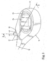
- FIG. 1 is a perspective view of a first embodiment of a reversible ratchet type wrench in accordance with the present invention.
- FIG. 2 is an exploded perspective view of the reversible ratchet type wrench in FIG. 1.
- FIG. 3 is a perspective view, partly cutaway, of the wrench in FIG. 2, illustrating formation of a slot in a bulge portion of a box end of the wrench by a cutter.
- FIG. 4 is a perspective view similar to FIG. 3, wherein formation of the slot is completed.
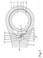
- FIG. 5 is a sectional view taken along plane 5 - 5 in FIG. 1.
- FIG. 6 is a sectional view taken along plane 6 - 6 in FIG. 5.
- FIG. 7 is a sectional view taken along plane 7 - 7 in FIG. 5.
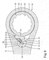
- FIG. 8 is a view similar to FIG. 6, wherein a switch member of the wrench is in a position allowing ratcheting in a reverse direction.
- FIG. 9 is a view similar to FIG. 6, wherein the switch member of the wrench is in a position allowing ratcheting in a reverse direction.
- FIG. 10 is a perspective view illustrating a portion of a second embodiment of the wrench in accordance with the present invention.
- FIG. 11 is a schematic top view of the second embodiment of the wrench.
- FIG. 12 is a sectional view of the wrench in FIG. 11.
- FIG. 13 is perspective view illustrating a portion of a third embodiment of the wrench in accordance with the present invention.
- FIG. 14 is a schematic top view illustrating formation of a slot in a bulge portion of the box end of the wrench in FIG. 13.
- FIG. 15 is a sectional view illustrating formation of a slot in a bulge portion of the box end of the wrench in FIG. 13.
- FIG. 15A is a perspective view illustrating a modified embodiment of the wrench in accordance with the present invention.
- FIG. 16 is an exploded perspective view of a conventional reversible ratchet type wrench.
- FIG. 17 is a sectional view of the reversible ratchet type wrench in FIG. 16.
- a first embodiment of a reversible ratchet type wrench in accordance with the present invention is designated by “ 10 ” and generally comprises a handle 12 having a box end 11 extending from an end of the handle 12 .
- a bulge portion 13 is formed in a conjunctive area between the handle 12 and the box end 10 .
- An annular groove 141 is defined in an end of a peripheral wall defining a hole 14 in the box end 11
- an annular ledge 142 is formed on the other end of the peripheral wall defining the hole 14 of the box end 11 .
- a drive member (e.g., a gear wheel) 20 is rotatably mounted in the hole 14 of the box end 11 and includes an inner periphery 24 for driving a fastener.
- the gear wheel 20 further includes an outer periphery having a first end with an annular groove 21 , a second end with a recessed portion 22 , and an intermediate portion with a plurality of teeth 23 .
- the gear wheel 20 is received in the hole 14 of the box end 11 with a C-clip 25 partially engaged in the annular groove 141 of the box end 11 and partially engaged in the annular groove 21 of the gear wheel 20 and with the recessed portion 22 of the second end of the gear wheel 20 abutting on the annular ledge 142 of the box end 11 .
- the drive member (now designated by 20 ′) includes a drive column 26 instead of the inner periphery in the first embodiment.
- the wrench can be used with a socket (not shown).
- a compartment 15 is defined in a peripheral wall defining the hole 14 of the box end 11 and communicated with the hole 14 .
- a receiving hole 16 extends from a side of the box end 11 toward the other side of the box end 11 but spaced from the other side of the box end 11 .
- the receiving hole 16 intersects with the compartment 15 .
- the receiving hole 16 extends in a direction perpendicular to a general plane of the compartment 15 .
- a slot 17 is defined in the bulge portion 13 and communicated with the receiving hole 16 .
- a pawl 30 is slidably mounted in the compartment 15 of the box end 11 and includes a toothed first side 31 and a second side opposite to the first side 31 .
- the second side of the pawl 30 includes a retaining groove 32 with two sides.
- the pawl 30 includes a first abutting end 33 and a second abutting end 33 for abutting against a wall defining the compartment 15 that receives the pawl 30 .
- a pivotal member 50 is rotatably mounted in the receiving hole 16 and includes an end with an engaging groove 51 . Further, the pivotal member 50 includes a receptacle 52 in a periphery thereof for receiving a biasing means 60 comprised of an elastic element (e.g., a spring 62 ) and a pressing member (e.g., a pin 61 ) having a blind hole 611 for receiving a portion of the spring 62 . Further, the pivotal member 50 includes two grooves 53 and 54 in the periphery and located on both sides of the receptacle 52 .
- a biasing means 60 comprised of an elastic element (e.g., a spring 62 ) and a pressing member (e.g., a pin 61 ) having a blind hole 611 for receiving a portion of the spring 62 .
- the pivotal member 50 includes two grooves 53 and 54 in the periphery and located on both sides of the receptacle 52 .
- a switch member 40 includes a first end 42 engaged in the engaging groove 51 of the pivotal member 50 and a second end 41 outside the box end 11 of the wrench 10 . It is appreciated that the switch member 40 extends through the slot 17 of the bulge portion 13 of the wrench 10 , and the slot 17 is sufficiently long to allow pivotal movement of the switch member 40 .
- the engaging groove 51 is preferably I-shaped for securely receiving the first end 42 of the switch member 40 having a corresponding configuration.
- the second end 42 of the switch member 40 is wide enough to avoid painful feeling in the user's finger during switching.
- FIG. 3 illustrates formation of the slot 17 in the bulge portion 13 of the box end 11 by means of milling by a cutter 0 . 70 . As illustrated in FIG. 4, after formation, the slot 17 is communicated with an end of the receiving hole 16 .
- the pin 61 is biased by the spring 62 to press against a side of the retaining groove 32 , which, in turn, biases the pawl 30 to engage with the teeth 23 of the gear wheel 20 with an abutting end 33 of the pawl 30 pressing against a portion of the wall defining the compartment 15 .
- the wrench allows ratcheting in the counterclockwise direction and allows free rotation in the clockwise direction. It is noted that a portion of the pawl 30 is received in the receiving groove 53 of the pivotal member 50 , thereby preventing disengagement of the pivotal member 50 from the receiving hole 16 .
- the pin 61 is biased by the spring 62 to press against the other side of the retaining groove 32 , which, in turn, biases the pawl 30 to engage with the teeth 23 of the gear wheel 20 with the other abutting end 33 of the pawl 30 pressing against another portion of the wall defining the compartment 15 .
- the wrench allows ratcheting in the clockwise direction and allows free rotation in the counterclockwise direction. It is noted that a portion of the pawl 30 is received in the other receiving groove 54 of the pivotal member 50 , thereby preventing disengagement of the pivotal member 50 from the receiving hole 16 .
- FIGS. 10 through 12 illustrate a second embodiment of the invention, wherein the bulge portion 13 of the box end 11 includes an arcuate portion 18 such that a portion of the slot 17 is exposed, best shown in FIG. 11.
- the switch member 40 may have a shorter length, and the second end (now designated by 42 ′) of the switch member 40 may be wider to further avoid painful feeling in the user's finger during switching.
- FIGS. 13 through 15 illustrate a third embodiment of the invention, wherein the bulge portion 13 includes an end edge 19 extending away from the receiving hole 16 to a position beyond a peripheral wall defining the receiving hole 16 , best shown in FIG. 15.
- FIGS. 14 and 15 illustrate formation of the slot 17 by means of milling by a cutter 70 that moves along a direction perpendicular to a longitudinal axis of the handle 12 .
- the end edge 19 is curved, best shown in FIG. 14.
- the end edge 19 may shield most part of the switch member 40 except the second end 42 of the switch member 40 . Thus, the risk of inadvertent impingement to the switch member 40 is lowered.
Abstract
A reversible ratchet type wrench handle comprises a box end extending from an end of the handle and having a hole. A compartment is defined in a peripheral wall defining the hole of the box end and communicated with the hole. A receiving hole extends from a side of the box end toward the other side of the box end but spaced from the other side of the box end. The receiving hole intersects the compartment. A bulge portion is formed in a conjunctive area between the handle and the box end. A slot is defined in the bulge portion and communicated with the compartment.
Description
- 1. Field of the Invention
- The present invention relates to a reversible ratchet type wrench of the type having a bulged portion in a box end thereof, wherein a slot is defined in the bulge portion for installation of a switch member for switching ratcheting directions of the wrench.
- 2. Description of the Related Art
- FIG. 16 of the drawings is an exploded perspective view of a conventional reversible ratchet type wrench comprising a
handle 3 and abox end 2 extending from thehandle 3. FIG. 17 is a sectional view of the reversible ratchet type wrench. A bulge portion 4 is formed in a conjunctive area between thehandle 3 and thebox end 2. A gear wheel 1 is rotatably mounted in ahole 7 defined in thebox end 2. Acompartment 6 is defined in a peripheral wall defining thebox end 2 for receiving apawl 9. Areceptacle 94 is defined in a wall defining thecompartment 6 and facing thehole 7. Aspring 92 and aball 93 are mounted in thereceptacle 94 for biasing thepawl 9 to engage with the gear wheel 1. Aslot 5 is defined in the bulge portion 4 and communicated with thecompartment 6. A switch member 8 includes a first end with aprotrusion 82 for engaging with a notch orgroove 91 in an upper side of thepawl 9. The switch member 8 further includes asecond end 81 extending outside of thecompartment 6 through theslot 5 for manual operation. Thus, the user may switch thesecond end 81 of theswitch member 91 between two positions corresponding to two ratcheting directions of the wrench. However, oil, dirt, ashes, or larger alien objects may enter thecompartment 6 through theslot 5 such that the wrench could not be used after thepawl 9 has stuck. Further, the switch member 8 would move together with thepawl 9 during operation of the wrench. The engagement between thepawl 9 and the gear wheel 1 is adversely affected if thesecond end 81 of the switch member 8 is inadvertently impinged by the user's finger or an alien object. As a result, the torque of the wrench is adversely affected. - An object of the present invention is to provide a reversible ratchet type wrench that prevents entrance of alien objects into an interior of the wrench and that provides reliable engagement between the drive member (e.g., a gear wheel) and the pawl.
- In accordance with a first aspect of the invention, there is provided a reversible ratchet type wrench comprising:
- a handle;
- a box end extending from an end of the handle and having a first side and a second side opposite to the first side, a hole being defined in the box end, a compartment being defined in a peripheral wall defining the hole of the box end and communicated with the hole, a receiving hole extending from the first side of the box end toward the second side of the box end but spaced from the second side of the box end, the receiving hole intersecting the compartment;
- a bulge portion formed in a conjunctive area between the handle and the box end, a slot being defined in the bulge portion and communicated with the compartment;
- a drive member rotatably mounted in the hole of the box end and including a plurality of teeth on an outer periphery thereof;
- a pawl slidably mounted in the compartment of the box end and including a toothed side;
- a pivotal member rotatably mounted in the receiving hole of the box end;
- a switch member extending through the slot of the bulge portion, the switch member including a first end securely engaged with the pivotal member to move therewith and a second end outside the box end for manual operation between two positions corresponding to two ratcheting directions of the wrench;
- a pressing member mounted between the pawl and the pivotal member; and
- an elastic element for biasing the pressing member against the pawl.
- Oil, dirt, ashes, or larger alien objects could not enter the compartment through the slot, as they will be obstructed by the pivotal member in the compartment. Formation of the slot is easy. Further, the switch member would not move together with the pawl during operation of the wrench. The engagement between the pawl and the drive member is not adversely affected.
- In accordance with a second aspect of the invention, there is provided a reversible ratchet type wrench handle comprising:
- a box end extending from an end of the handle and having a first side and a second side opposite to the first side, a hole being defined in the box end, a compartment being defined in a peripheral wall defining the hole of the box end and communicated with the hole, a receiving hole extending from the first side of the box end toward the second side of the box end but spaced from the second side of the box end, the receiving hole intersecting the compartment; and
- a bulge portion formed in a conjunctive area between the handle and the box end, a slot being defined in the bulge portion and communicated with the compartment.
- Other objects, advantages, and novel features of the invention will become more apparent from the following detailed description when taken in conjunction with the accompanying drawings.
- FIG. 1 is a perspective view of a first embodiment of a reversible ratchet type wrench in accordance with the present invention.
- FIG. 2 is an exploded perspective view of the reversible ratchet type wrench in FIG. 1.
- FIG. 3 is a perspective view, partly cutaway, of the wrench in FIG. 2, illustrating formation of a slot in a bulge portion of a box end of the wrench by a cutter.
- FIG. 4 is a perspective view similar to FIG. 3, wherein formation of the slot is completed.
- FIG. 5 is a sectional view taken along plane 5-5 in FIG. 1.
- FIG. 6 is a sectional view taken along plane 6-6 in FIG. 5.
- FIG. 7 is a sectional view taken along plane 7-7 in FIG. 5.
- FIG. 8 is a view similar to FIG. 6, wherein a switch member of the wrench is in a position allowing ratcheting in a reverse direction.
- FIG. 9 is a view similar to FIG. 6, wherein the switch member of the wrench is in a position allowing ratcheting in a reverse direction.
- FIG. 10 is a perspective view illustrating a portion of a second embodiment of the wrench in accordance with the present invention.
- FIG. 11 is a schematic top view of the second embodiment of the wrench.
- FIG. 12 is a sectional view of the wrench in FIG. 11.
- FIG. 13 is perspective view illustrating a portion of a third embodiment of the wrench in accordance with the present invention.
- FIG. 14 is a schematic top view illustrating formation of a slot in a bulge portion of the box end of the wrench in FIG. 13.
- FIG. 15 is a sectional view illustrating formation of a slot in a bulge portion of the box end of the wrench in FIG. 13.
- FIG. 15A is a perspective view illustrating a modified embodiment of the wrench in accordance with the present invention.
- FIG. 16 is an exploded perspective view of a conventional reversible ratchet type wrench.
- FIG. 17 is a sectional view of the reversible ratchet type wrench in FIG. 16.
- Referring to FIGS. 1, 2, and 5, a first embodiment of a reversible ratchet type wrench in accordance with the present invention is designated by “10” and generally comprises a
handle 12 having abox end 11 extending from an end of thehandle 12. Abulge portion 13 is formed in a conjunctive area between thehandle 12 and thebox end 10. Anannular groove 141 is defined in an end of a peripheral wall defining ahole 14 in thebox end 11, and anannular ledge 142 is formed on the other end of the peripheral wall defining thehole 14 of thebox end 11. - A drive member (e.g., a gear wheel) 20 is rotatably mounted in the
hole 14 of thebox end 11 and includes aninner periphery 24 for driving a fastener. Thegear wheel 20 further includes an outer periphery having a first end with anannular groove 21, a second end with a recessedportion 22, and an intermediate portion with a plurality ofteeth 23. Thegear wheel 20 is received in thehole 14 of thebox end 11 with a C-clip 25 partially engaged in theannular groove 141 of thebox end 11 and partially engaged in theannular groove 21 of thegear wheel 20 and with the recessedportion 22 of the second end of thegear wheel 20 abutting on theannular ledge 142 of thebox end 11. Thus, theannular ledge 142 of thebox end 11 prevents disengagement of thegear wheel 20. In an alternative embodiment, as shown in FIG. 15, the drive member (now designated by 20′) includes adrive column 26 instead of the inner periphery in the first embodiment. Thus, the wrench can be used with a socket (not shown). - A
compartment 15 is defined in a peripheral wall defining thehole 14 of thebox end 11 and communicated with thehole 14. A receivinghole 16 extends from a side of thebox end 11 toward the other side of thebox end 11 but spaced from the other side of thebox end 11. The receivinghole 16 intersects with thecompartment 15. Preferably, the receivinghole 16 extends in a direction perpendicular to a general plane of thecompartment 15. Aslot 17 is defined in thebulge portion 13 and communicated with the receivinghole 16. - A
pawl 30 is slidably mounted in thecompartment 15 of thebox end 11 and includes a toothedfirst side 31 and a second side opposite to thefirst side 31. The second side of thepawl 30 includes a retaininggroove 32 with two sides. Further, thepawl 30 includes a firstabutting end 33 and a secondabutting end 33 for abutting against a wall defining thecompartment 15 that receives thepawl 30. - A
pivotal member 50 is rotatably mounted in the receivinghole 16 and includes an end with an engaginggroove 51. Further, thepivotal member 50 includes areceptacle 52 in a periphery thereof for receiving a biasing means 60 comprised of an elastic element (e.g., a spring 62) and a pressing member (e.g., a pin 61) having ablind hole 611 for receiving a portion of thespring 62. Further, thepivotal member 50 includes twogrooves receptacle 52. - A
switch member 40 includes afirst end 42 engaged in the engaginggroove 51 of thepivotal member 50 and asecond end 41 outside thebox end 11 of thewrench 10. It is appreciated that theswitch member 40 extends through theslot 17 of thebulge portion 13 of thewrench 10, and theslot 17 is sufficiently long to allow pivotal movement of theswitch member 40. As illustrated in FIG. 2, the engaginggroove 51 is preferably I-shaped for securely receiving thefirst end 42 of theswitch member 40 having a corresponding configuration. Thesecond end 42 of theswitch member 40 is wide enough to avoid painful feeling in the user's finger during switching. - FIG. 3 illustrates formation of the
slot 17 in thebulge portion 13 of thebox end 11 by means of milling by a cutter 0.70. As illustrated in FIG. 4, after formation, theslot 17 is communicated with an end of the receivinghole 16. - When the
switch member 40 is in a position shown in FIGS. 6 and 7, thepin 61 is biased by thespring 62 to press against a side of the retaininggroove 32, which, in turn, biases thepawl 30 to engage with theteeth 23 of thegear wheel 20 with anabutting end 33 of thepawl 30 pressing against a portion of the wall defining thecompartment 15. Thus, the wrench allows ratcheting in the counterclockwise direction and allows free rotation in the clockwise direction. It is noted that a portion of thepawl 30 is received in the receivinggroove 53 of thepivotal member 50, thereby preventing disengagement of thepivotal member 50 from the receivinghole 16. - When the
switch member 40 is in a position shown in FIGS. 8 and 9, thepin 61 is biased by thespring 62 to press against the other side of the retaininggroove 32, which, in turn, biases thepawl 30 to engage with theteeth 23 of thegear wheel 20 with the other abuttingend 33 of thepawl 30 pressing against another portion of the wall defining thecompartment 15. Thus, the wrench allows ratcheting in the clockwise direction and allows free rotation in the counterclockwise direction. It is noted that a portion of thepawl 30 is received in the other receivinggroove 54 of thepivotal member 50, thereby preventing disengagement of thepivotal member 50 from the receivinghole 16. - In either position, alien objects, oil, or dirt are not allowed to enter the
compartment 15 that receives thepawl 30, as they will be obstructed by thepivotal member 50 in the receivinghole 16. Further, theswitch member 40 would not move together with thepawl 30 during operation of the wrench. The engagement between thepawl 30 and thegear wheel 20 is not adversely affected. - FIGS. 10 through 12 illustrate a second embodiment of the invention, wherein the
bulge portion 13 of thebox end 11 includes anarcuate portion 18 such that a portion of theslot 17 is exposed, best shown in FIG. 11. Thus, theswitch member 40 may have a shorter length, and the second end (now designated by 42′) of theswitch member 40 may be wider to further avoid painful feeling in the user's finger during switching. - FIGS. 13 through 15 illustrate a third embodiment of the invention, wherein the
bulge portion 13 includes anend edge 19 extending away from the receivinghole 16 to a position beyond a peripheral wall defining the receivinghole 16, best shown in FIG. 15. FIGS. 14 and 15 illustrate formation of theslot 17 by means of milling by acutter 70 that moves along a direction perpendicular to a longitudinal axis of thehandle 12. Preferably, theend edge 19 is curved, best shown in FIG. 14. Theend edge 19 may shield most part of theswitch member 40 except thesecond end 42 of theswitch member 40. Thus, the risk of inadvertent impingement to theswitch member 40 is lowered. - According to the above description, it is noted that oil, dirt, ashes, or larger alien objects could not enter the
compartment 15 through theslot 17. Formation of theslot 17 is easy. Further, theswitch member 40 would not move together with thepawl 30 during operation of the wrench. The engagement between thepawl 30 and thegear wheel 20 is not adversely affected. - Although the invention has been explained in relation to its preferred embodiment, it is to be understood that many other possible modifications and variations can be made without departing from the scope of the invention as hereinafter claimed.
Claims (20)
1. A reversible ratchet type wrench comprising:
a handle;
a box end extending from an end of the handle and having a first side and a second side opposite to the first side, a hole being defined in the box end, a compartment being defined in a peripheral wall defining the hole of the box end and communicated with the hole, a receiving hole extending from the first side of the box end toward the second side of the box end but spaced from the second side of the box end, the receiving hole intersecting the compartment;
a bulge portion formed in a conjunctive area between the handle and the box end, a slot being defined in the bulge portion and communicated with the compartment;
a drive member rotatably mounted in the hole of the box end and including a plurality of teeth on an outer periphery thereof;
a pawl slidably mounted in the compartment of the box end and including a toothed side;
a pivotal member rotatably mounted in the receiving hole of the box end;
a switch member extending through the slot of the bulge portion, the switch member including a first end securely engaged with the pivotal member to move therewith and a second end outside the box end for manual operation between two positions corresponding to two ratcheting directions of the wrench;
a pressing member mounted between the pawl and the pivotal member; and
an elastic element for biasing the pressing member against the pawl.
2. The reversible ratchet type wrench as claimed in claim 1 , wherein the outer periphery of the drive member includes an end with an annular groove, the peripheral wall defining the hole of the box end including an annular groove in an end thereof, further including a C-clip partially received in the annular groove of the drive member and partially received in the annular groove of the peripheral wall defining the hole of the box end.
3. The reversible ratchet type wrench as claimed in claim 1 , wherein the wherein the outer periphery of the drive member includes an end with a recessed portion, the peripheral wall defining the hole of the box end including an annular ledge on an end thereof, the recessed portion of the drive member abutting on the annular ledge of the box end, thereby preventing disengagement of the drive member.
4. The reversible ratchet type wrench as claimed in claim 2 , wherein the wherein the outer periphery of the drive member includes another end with a recessed portion, the peripheral wall defining the hole of the box end including an annular ledge on another end thereof, the recessed portion of the drive member abutting on the annular ledge of the box end, thereby preventing disengagement of the drive member.
5. The reversible ratchet type wrench as claimed in claim 1 , wherein the slot of the bulge portion is communicated with an end of the compartment of the box end.
6. The reversible ratchet type wrench as claimed in claim 1 , wherein the pivotal member includes an engaging groove on an end thereof for securely receiving the first end of the switch member.
7. The reversible ratchet type wrench as claimed in claim 6 , wherein the engaging groove of the pivotal member is substantially I-shaped.
8. The reversible ratchet type wrench as claimed in claim 1 , wherein the pivotal member includes a receptacle in an outer periphery thereof for receiving the elastic element and the pressing member.
9. The reversible ratchet type wrench as claimed in claim 6 , wherein the pivotal member includes a receptacle in an outer periphery thereof for receiving the elastic element and the pressing member.
10. The reversible ratchet type wrench as claimed in claim 8 , wherein the pressing member includes a blind hole in an end thereof for receiving an end of the elastic element.
11. The reversible ratchet type wrench as claimed in claim 8 , wherein the pivotal member further includes two grooves located on both sides of the receptacle, a portion of the pawl being selectively received in one of the grooves, thereby preventing disengagement of the pivotal member from the receiving hole.
12. The reversible ratchet type wrench as claimed in claim 9 , wherein the pressing member includes a blind hole in an end thereof for receiving an end of the elastic element.
13. The reversible ratchet type wrench as claimed in claim 1 , wherein the pawl includes a second side opposite to the toothed side, a retaining groove being defined in the second side of the pawl and including two sides, the pressing member being biased by the elastic element to selectively press against one of the sides of the retaining groove.
14. The reversible ratchet type wrench as claimed in claim 13 , wherein the pawl further includes two abutting ends for selectively abutting against a wall defining the compartment.
15. The reversible ratchet type wrench as claimed in claim 1 , wherein the bulge portion includes an arcuate portion, leaving a portion of the slot exposed.
16. The reversible ratchet type wrench as claimed in claim 1 , wherein the bulge portion including an end edge extending away from the receiving hole to a position beyond a peripheral wall defining the receiving hole.
17. A reversible ratchet type wrench handle comprising:
a box end extending from an end of the handle and having a first side and a second side opposite to the first side, a hole being defined in the box end, a compartment being defined in a peripheral wall defining the hole of the box end and communicated with the hole, a receiving hole extending from the first side of the box end toward the second side of the box end but spaced from the second side of the box end, the receiving hole intersecting the compartment; and
a bulge portion formed in a conjunctive area between the handle and the box end, a slot being defined in the bulge portion and communicated with the compartment.
18. The reversible ratchet type wrench as claimed in claim 17 , wherein the slot of the bulge portion is communicated with an end of the compartment of the box end.
19. The reversible ratchet type wrench as claimed in claim 17 , wherein the bulge portion includes an arcuate portion, leaving a portion of the slot exposed.
20. The reversible ratchet type wrench as claimed in claim 17 , wherein the bulge portion including an end edge extending away from the receiving hole to a position beyond a peripheral wall defining the receiving hole.
Priority Applications (1)
| Application Number | Priority Date | Filing Date | Title |
|---|---|---|---|
| US10/131,105 US6945141B2 (en) | 2002-04-22 | 2002-04-22 | Reversible ratchet type wrench |
Applications Claiming Priority (1)
| Application Number | Priority Date | Filing Date | Title |
|---|---|---|---|
| US10/131,105 US6945141B2 (en) | 2002-04-22 | 2002-04-22 | Reversible ratchet type wrench |
Publications (2)
| Publication Number | Publication Date |
|---|---|
| US20030196522A1 true US20030196522A1 (en) | 2003-10-23 |
| US6945141B2 US6945141B2 (en) | 2005-09-20 |
Family
ID=29215555
Family Applications (1)
| Application Number | Title | Priority Date | Filing Date |
|---|---|---|---|
| US10/131,105 Expired - Fee Related US6945141B2 (en) | 2002-04-22 | 2002-04-22 | Reversible ratchet type wrench |
Country Status (1)
| Country | Link |
|---|---|
| US (1) | US6945141B2 (en) |
Cited By (9)
| Publication number | Priority date | Publication date | Assignee | Title |
|---|---|---|---|---|
| US20050044997A1 (en) * | 2003-08-25 | 2005-03-03 | Liu Ling Lang | High torsional force structure for a ratchet device |
| US20050103166A1 (en) * | 2003-11-19 | 2005-05-19 | Terence Chen | Selective one-way wrench |
| US20050126347A1 (en) * | 2003-12-11 | 2005-06-16 | Terence Chen | Selective one-way wrench |
| US20060130614A1 (en) * | 2004-10-12 | 2006-06-22 | Easco Hand Tools, Inc. | Method of forming a pawl pocket for a ratcheting tool and tool thereby formed |
| CN100339186C (en) * | 2004-01-21 | 2007-09-26 | 陈泰佐 | Reversible driving rotary spanner |
| CN102305250A (en) * | 2011-07-27 | 2012-01-04 | 易联工业股份有限公司 | Bidirectional clutch |
| USRE43286E1 (en) | 1999-08-03 | 2012-04-03 | Bobby Hu | Ratchet wheel with asymmetric arcuate concave teeth or non-arcuate concave teeth ratcheting tools with such ratchet wheel and combination of such ratchet wheel and a pawl |
| US8820195B2 (en) | 2010-07-01 | 2014-09-02 | Stanley Black & Decker, Inc. | Bit or fastener driver |
| USD887233S1 (en) * | 2017-05-22 | 2020-06-16 | Grip Holdings Llc | Extractor socket |
Families Citing this family (12)
| Publication number | Priority date | Publication date | Assignee | Title |
|---|---|---|---|---|
| US20060117913A1 (en) * | 2003-08-27 | 2006-06-08 | Terence Chen | Selective one-way wrench |
| US7121171B2 (en) * | 2004-08-06 | 2006-10-17 | Chih-Ching Hsien | Ratchet control structure of bidirectional ratchet spanner |
| US7062994B2 (en) * | 2004-10-14 | 2006-06-20 | Ching Chen | Ratchet wrench |
| US8833631B2 (en) | 2011-05-16 | 2014-09-16 | John J. Munro, III | Delivery applicator for radioactive staples for brachytherapy medical treatment |
| US20070277652A1 (en) * | 2006-05-30 | 2007-12-06 | Hsien-Chung Tuan-Mu | Reversible ratcheting tool |
| US9079297B2 (en) | 2011-04-15 | 2015-07-14 | Apex Brands, Inc. | Flex-head wrench |
| US8347763B1 (en) * | 2011-06-17 | 2013-01-08 | Chin-Hui Chu | Wrench with a quickly rotatable driving head |
| US9815179B2 (en) | 2012-09-26 | 2017-11-14 | Apex Brands, Inc. | Reversible ratcheting tool with dual pawls |
| US9821441B2 (en) * | 2014-02-13 | 2017-11-21 | Yi-Fu Chen | Ratchet wrench |
| US9327389B2 (en) * | 2014-02-25 | 2016-05-03 | Yi-Fu Chen | Ratchet wrench |
| US9248556B1 (en) * | 2014-07-08 | 2016-02-02 | Zhi-Ji Chen | Positioning device for ratchet wrench |
| US20190314959A1 (en) * | 2018-04-16 | 2019-10-17 | Yi-Fu Chen | Switch device for ratchet wrench |
Citations (61)
| Publication number | Priority date | Publication date | Assignee | Title |
|---|---|---|---|---|
| US70512A (en) * | 1867-11-05 | Improvement in carburetting gases and aie | ||
| US93995A (en) * | 1869-08-24 | Improved sash-balance | ||
| US726012A (en) * | 1903-01-20 | 1903-04-21 | Howard Emmet Andrew | Nut-wrench. |
| US878657A (en) * | 1906-01-02 | 1908-02-11 | Arthur Munch | Ratchet-wrench. |
| US893097A (en) * | 1907-09-27 | 1908-07-14 | Joseph M Reams | Reversible ratchet-wrench. |
| US1090578A (en) * | 1911-06-10 | 1914-03-17 | Joseph B Smythe | Ratchet mechanism. |
| US1639078A (en) * | 1925-03-14 | 1927-08-16 | John E Coe | Ratchet wrench |
| US1680515A (en) * | 1926-12-21 | 1928-08-14 | Buda Co | Ratchet mechanism for lifting jacks |
| US2735324A (en) * | 1956-02-21 | Friction action ratchet wrench | ||
| US2803980A (en) * | 1955-12-27 | 1957-08-27 | Irwin R Vogel | Reversible ratchet wrench |
| US3044591A (en) * | 1959-08-31 | 1962-07-17 | Luther E Kilness | Ratchet mechanism |
| US3233481A (en) * | 1963-10-25 | 1966-02-08 | Kelsey Hayes Co | Ratchet wrench |
| US3269496A (en) * | 1964-06-22 | 1966-08-30 | Luther E Kilness | Reversible one way clutch for wrench |
| US3342229A (en) * | 1965-10-21 | 1967-09-19 | James Igor | Ratchet handle screwdriver |
| US3598001A (en) * | 1969-02-14 | 1971-08-10 | Lowell Corp | Reversible ratchet handle for socket wrench |
| US3606940A (en) * | 1969-01-11 | 1971-09-21 | Walter Finkeldei Werkzeugfabri | Ratchet switchable into opposite directions of operation |
| US3783703A (en) * | 1972-11-17 | 1974-01-08 | Jo Line Tools | Ratchet mechanism |
| US3866492A (en) * | 1974-03-06 | 1975-02-18 | Jo Line Tools | Torque multiplier |
| US3970155A (en) * | 1974-01-14 | 1976-07-20 | Jo-Line Tools, Inc. | Electronic torque wrench |
| US4053037A (en) * | 1976-06-10 | 1977-10-11 | Jo-Line Tools, Inc. | Reversing ratchet |
| US4147076A (en) * | 1977-10-31 | 1979-04-03 | The Wright Tool And Forge Company | Reversing-ratchet socket wrench |
| US4257507A (en) * | 1978-08-15 | 1981-03-24 | Jo-Line Tools, Inc. | Torque wrench with pawl guide |
| US4512218A (en) * | 1984-03-19 | 1985-04-23 | Chow Kirk K | Control bar for ratchet wrench |
| US4777852A (en) * | 1986-10-02 | 1988-10-18 | Snap-On Tools Corporation | Ratcheting screwdriver |
| US4924737A (en) * | 1989-03-20 | 1990-05-15 | Gummow Tool Company | Positive drive ratchet |
| US5000066A (en) * | 1983-07-05 | 1991-03-19 | Gentiluomo Paul A | Ratchet wrench |
| US5038452A (en) * | 1988-01-28 | 1991-08-13 | Latshaw Enterprises, Inc. | Method of assembling an improved ratcheting tool driver |
| US5347892A (en) * | 1993-03-11 | 1994-09-20 | Moetteli John B | Socket retainer for thin-wall drive member |
| US5404773A (en) * | 1992-08-10 | 1995-04-11 | Norville; Burl O. | Cam-action ratchet-type wrench |
| US5448931A (en) * | 1989-07-28 | 1995-09-12 | Great Bay Tool Corp. | Adjustable wrench |
| US5522288A (en) * | 1994-12-09 | 1996-06-04 | Snap-On Incorporated | Reversible ratchet wrench |
| US5535646A (en) * | 1995-02-07 | 1996-07-16 | Stanley Mechanics Tools, Inc. | Ratchet drive |
| US5622089A (en) * | 1995-12-14 | 1997-04-22 | Gifford, Sr.; Robert W. | Ratchet wrench with thumb activated direction control switch |
| US5749272A (en) * | 1996-04-24 | 1998-05-12 | Phan; Tan Thanh | Ratchet screw driver |
| US5878635A (en) * | 1996-04-16 | 1999-03-09 | Hsieh; Chih-Ching | Reversible ratchet wrench |
| US5884537A (en) * | 1997-06-20 | 1999-03-23 | Chen; Chun Chiung | Ratchet tool |
| US5884538A (en) * | 1997-06-13 | 1999-03-23 | Hand Tool Design Corporation | Detent for a hand tool |
| US5887493A (en) * | 1994-07-14 | 1999-03-30 | Main; Harvey M. | Ratchet wrench |
| US6125722A (en) * | 1999-03-18 | 2000-10-03 | Snap-On Tools Company | Ratchet wrench with sealed reversing lever |
| USD434292S (en) * | 1999-08-20 | 2000-11-28 | Chih-Ching Hsieh | Wrench |
| US6155140A (en) * | 1999-09-09 | 2000-12-05 | Tsai; Tzen Chang | Ratchet wrench |
| US6164167A (en) * | 1998-06-22 | 2000-12-26 | Chen; Yu-Tang | Ratchet wrench having gear driven pawl |
| US6308594B1 (en) * | 2000-12-28 | 2001-10-30 | Chin-Shun Cheng | Ratchet wrench structure |
| US6334373B1 (en) * | 2000-04-18 | 2002-01-01 | Chih-Ching Hsieh | Ratchet wrench stop member positioning arrangement |
| US6382052B1 (en) * | 2001-04-02 | 2002-05-07 | Shwu Ruu Chen | Ratchet tool |
| US6382051B1 (en) * | 2001-09-05 | 2002-05-07 | Chih-Min Chang | Ratchet wrench |
| US6386072B1 (en) * | 2001-03-21 | 2002-05-14 | Chi Yuan-Chin | Ratchet tool |
| US6457388B1 (en) * | 2001-01-25 | 2002-10-01 | Ching Chen | Control member for ratchet wrench |
| US6516691B1 (en) * | 2001-07-27 | 2003-02-11 | Hung Yin Wei | Racheting tool with a tapered spring positioning member |
| US6539825B1 (en) * | 2001-09-20 | 2003-04-01 | Yen-Wen Lin | Single direction ratcheting wrench with stuck prevention and ratcheting direction indication |
| US6568299B2 (en) * | 1999-12-16 | 2003-05-27 | Bobby Hu | Reversible ratcheting tool with a smaller head |
| US6591717B2 (en) * | 2001-01-22 | 2003-07-15 | Hung Yin Wei | Plum blossom-shaped ratchet wrench structure |
| US6629477B2 (en) * | 2001-01-11 | 2003-10-07 | Hand Tool Design Corporation | Reversible ratchet wrench with high torsion |
| US6644148B2 (en) * | 2002-02-08 | 2003-11-11 | Bobby Hu | Reversible ratchet-type wrench |
| US6662693B2 (en) * | 2001-07-13 | 2003-12-16 | Bobby Hu | Wrench with a fixed maximum operational torque |
| US6666117B2 (en) * | 2001-07-13 | 2003-12-23 | Bobby Hu | Wrench with a fixed maximum operational torque |
| US6666112B2 (en) * | 2000-09-01 | 2003-12-23 | Bobby Hu | Switching arrangement for a reversible ratchet type wrench |
| US6732614B2 (en) * | 2001-02-19 | 2004-05-11 | Bobby Hu | Easy-to-manufacture and easy-to-assemble ratcheting-type wrench |
| US6745647B2 (en) * | 2000-11-29 | 2004-06-08 | Mei-Chen Wang | Wrench having a universal-joint ratchet wheel |
| US6748825B2 (en) * | 2002-04-22 | 2004-06-15 | Yung-Chung Hsu | One-way wrench |
| US6758641B2 (en) * | 2001-07-13 | 2004-07-06 | Bobby Hu | Method for manufacturing a ratchet type ring spanner having a larger cavity for receiving a larger pawl |
Family Cites Families (73)
| Publication number | Priority date | Publication date | Assignee | Title |
|---|---|---|---|---|
| US1194471A (en) | 1916-08-15 | Combihatiob | ||
| US15482A (en) | 1856-08-05 | Wrench | ||
| US810599A (en) | 1905-04-10 | 1906-01-23 | Eugene K Ansorge | Wrench. |
| US841686A (en) | 1906-11-20 | 1907-01-22 | John N Hatfield | Wrench. |
| US915446A (en) | 1908-09-23 | 1909-03-16 | Joseph M Kearnes | Wrench. |
| US1033358A (en) | 1911-12-09 | 1912-07-23 | John L Turner | Wrench. |
| US1078059A (en) | 1913-10-01 | 1913-11-11 | Frank Mossberg Company | Wrench. |
| US1261092A (en) | 1914-06-18 | 1918-04-02 | Fred R Allen | Wrench. |
| US1426127A (en) | 1920-04-23 | 1922-08-15 | Frank Mossberg Company | Ratchet wrench |
| US1382492A (en) | 1920-12-10 | 1921-06-21 | Evans Lafayette | Wrench |
| US1614039A (en) | 1924-02-01 | 1927-01-11 | Husky Wrench Company | Wrench |
| US1957462A (en) | 1933-01-25 | 1934-05-08 | Williams J H & Co | Ratchet wrench |
| US2193984A (en) | 1937-04-16 | 1940-03-19 | Armstrong Bros Tool Co | Reversible ratchet wrench |
| US2201705A (en) | 1938-07-19 | 1940-05-21 | Wright Tool And Forge Company | Ratchet wrench |
| US2201827A (en) | 1939-04-17 | 1940-05-21 | Otto P Froeschl | Ratchet mechanism |
| US2317461A (en) | 1940-03-22 | 1943-04-27 | Lucian C Jackson | Wrench |
| US2542241A (en) | 1946-10-23 | 1951-02-20 | New Britain Machine Co | Ratchet mechanism |
| US2657604A (en) | 1952-09-11 | 1953-11-03 | Sherman Klove Co | Ratchet wrench |
| US2701977A (en) | 1953-05-07 | 1955-02-15 | Wright Tool And Forge Company | Reversible ratchet wrench |
| US2800821A (en) | 1953-10-01 | 1957-07-30 | New Britain Machine Co | Angularly adjustable, reversible ratchet wrench |
| US2769360A (en) | 1954-09-10 | 1956-11-06 | Cottrell Wayne Woodford | Angular wrench head having upwardly opening socket |
| US2764048A (en) | 1955-02-07 | 1956-09-25 | Leslie V Thompson | Ratchet wrench |
| DE1140092B (en) | 1956-12-05 | 1962-11-22 | Daimler Benz Ag | Guide device for sliding doors for motor vehicles |
| US2957377A (en) | 1957-09-13 | 1960-10-25 | Terence G Hare | Reversible ratchet type wrench |
| US2891434A (en) | 1958-04-21 | 1959-06-23 | Lozensky Charles Andrew | Ratchet wrench |
| US3019682A (en) | 1960-04-08 | 1962-02-06 | Terence G Hare | Reversible ratchet type wrench |
| US3250157A (en) | 1963-11-06 | 1966-05-10 | Snap On Tools Corp | Magnetic ratchet mechanism for wrenches and the like |
| US3265171A (en) | 1964-06-22 | 1966-08-09 | Luther E Kilness | One way reversible clutch for wrench |
| US3337014A (en) | 1965-10-20 | 1967-08-22 | John A Sandrick | Ratchet wrench |
| US3393587A (en) | 1966-12-15 | 1968-07-23 | Wright Tool And Forge Company | Ratchet wrenches |
| US3393780A (en) | 1967-01-26 | 1968-07-23 | Luther E. Kilness | Reversible ratchet |
| US3436992A (en) | 1967-03-10 | 1969-04-08 | Pendleton Tool Ind Inc | Reversible ratchet wrench with floating pawls |
| US3577816A (en) | 1969-04-10 | 1971-05-04 | Jerry Alexander | Ratchet wrench |
| US3713356A (en) | 1971-01-18 | 1973-01-30 | Snap On Tools Corp | Socket release mechanism for wrenches and the like |
| US3908487A (en) | 1971-09-10 | 1975-09-30 | Stanley Works | Rotary hand tool |
| US3742788A (en) | 1972-07-20 | 1973-07-03 | Parker Mfg Co | Ratchet wrench |
| US3838614A (en) | 1972-12-12 | 1974-10-01 | Donnell W O | Reciprocating engine barring tool |
| US4111077A (en) | 1977-02-02 | 1978-09-05 | Lowell Corporation | Ratchet wrench |
| US4070932A (en) | 1977-03-01 | 1978-01-31 | Jeannotte Richard W | Extensible handle for a tool headpiece |
| US4128025A (en) | 1977-08-08 | 1978-12-05 | Main Harvey M | Bolt starting device |
| US4277989A (en) | 1979-05-01 | 1981-07-14 | Tracy Kurt L | Ratchet wrench handle |
| DE2918825A1 (en) | 1979-05-10 | 1980-11-20 | Foell Remswerk | RATCHET LEVER |
| US4274311A (en) | 1979-07-23 | 1981-06-23 | Emil Ebert | Ratchet wrench handle |
| US4277990A (en) | 1979-11-14 | 1981-07-14 | Duro Metal Products Company | Ratchet wrench |
| US4328720A (en) | 1980-03-17 | 1982-05-11 | Shiel Walter P | Socket wrench and set |
| US4308769A (en) | 1980-06-02 | 1982-01-05 | Bertha Rantanen | Reversing ratcheting wrench |
| US4336728A (en) | 1980-10-08 | 1982-06-29 | Deibert Raymond L | Push-button reversible ratchet and pawl socket wrench handle |
| US4406186A (en) | 1981-05-29 | 1983-09-27 | Gummow Stephen A | Dual action ratchet wrench |
| US4420995A (en) | 1981-06-05 | 1983-12-20 | Roberts Peter M | Quick-release and positive locking mechanism for use on socket wrenches and on power and impact tools |
| US4488460A (en) | 1982-07-28 | 1984-12-18 | Easco Corporation | Ergonomic handle for hand tool |
| US4520697A (en) | 1982-09-29 | 1985-06-04 | Moetteli John B | Ratchet wrench |
| US4631988A (en) | 1983-01-26 | 1986-12-30 | Colvin David S | Reversible ratchet wrench including detent mechanism |
| US4485700A (en) | 1983-01-26 | 1984-12-04 | Colvin David S | Reversible ratchet wrench |
| DE3407126A1 (en) | 1984-02-28 | 1985-08-29 | Enerpac GmbH, 4300 Essen | POWER SCREWDRIVER WITH A TENSION WHEEL WITH A FINE-STAGE TOOTHING |
| DE3561232D1 (en) | 1985-01-07 | 1988-02-04 | Wille Gmbh & Co | Ratchet wrench |
| US4662251A (en) | 1985-10-08 | 1987-05-05 | Kohal Lester L | Orthogonal adjustable socket wrench |
| US4807500A (en) | 1986-11-14 | 1989-02-28 | Main Harvey M | Reversing ratchet mechanism for tools |
| US4722253A (en) | 1987-01-21 | 1988-02-02 | Jessie Chow | Reversible ratchet wrench with one-hand accessible switch |
| US4762033A (en) | 1987-02-24 | 1988-08-09 | National Hand Tool Corporation | Ratchet wrench with manual disassembly capability |
| US4722252A (en) | 1987-03-02 | 1988-02-02 | Fulcher William A | Power driven wrench |
| US4869138A (en) | 1988-02-08 | 1989-09-26 | Farris Jim L | New and improved ratchet tool with rotatable rotor lock and rigid shifter finger |
| US4796492A (en) | 1988-05-20 | 1989-01-10 | Liou Mou Tang | Clutch type socket wrench |
| US4903554A (en) | 1988-06-02 | 1990-02-27 | Colvin David S | Reversible ratchet wrench with thin head construction |
| US4862775A (en) | 1988-10-19 | 1989-09-05 | Jessie Chow | Control device for ratchet wrenches |
| US4934220A (en) | 1989-04-03 | 1990-06-19 | Snap-On Tools Corporation | Sealed reversible ratchet wrench |
| EP0437007A1 (en) | 1989-07-20 | 1991-07-17 | Chiro Tools Mfg., Corp. | Improved wrench |
| US5076121A (en) | 1989-07-28 | 1991-12-31 | Gregory Fosella | Adjustable ratchet wrench |
| US5012705A (en) | 1990-03-16 | 1991-05-07 | National Hand Tool Corporation | Ratchet wrench with manually removable core |
| US4991468A (en) | 1990-08-10 | 1991-02-12 | Lee Clark J | Barrel type sockets |
| US5178047A (en) | 1991-08-08 | 1993-01-12 | Easco Hand Tools, Inc. | Reversible ratchet wrench |
| US5199330A (en) | 1991-10-01 | 1993-04-06 | Easco Hand Tools, Inc. | Reversing ratchet wrench |
| US5157994A (en) | 1991-12-13 | 1992-10-27 | Snap-On Tools Corporation | Ratchet wrench with lost motion reversing mechanism |
| US5144869A (en) | 1992-03-09 | 1992-09-08 | Jessie Chow | Control device for ratchet wrenches |
-
2002
- 2002-04-22 US US10/131,105 patent/US6945141B2/en not_active Expired - Fee Related
Patent Citations (62)
| Publication number | Priority date | Publication date | Assignee | Title |
|---|---|---|---|---|
| US2735324A (en) * | 1956-02-21 | Friction action ratchet wrench | ||
| US93995A (en) * | 1869-08-24 | Improved sash-balance | ||
| US70512A (en) * | 1867-11-05 | Improvement in carburetting gases and aie | ||
| US726012A (en) * | 1903-01-20 | 1903-04-21 | Howard Emmet Andrew | Nut-wrench. |
| US878657A (en) * | 1906-01-02 | 1908-02-11 | Arthur Munch | Ratchet-wrench. |
| US893097A (en) * | 1907-09-27 | 1908-07-14 | Joseph M Reams | Reversible ratchet-wrench. |
| US1090578A (en) * | 1911-06-10 | 1914-03-17 | Joseph B Smythe | Ratchet mechanism. |
| US1639078A (en) * | 1925-03-14 | 1927-08-16 | John E Coe | Ratchet wrench |
| US1680515A (en) * | 1926-12-21 | 1928-08-14 | Buda Co | Ratchet mechanism for lifting jacks |
| US2803980A (en) * | 1955-12-27 | 1957-08-27 | Irwin R Vogel | Reversible ratchet wrench |
| US3044591A (en) * | 1959-08-31 | 1962-07-17 | Luther E Kilness | Ratchet mechanism |
| US3233481A (en) * | 1963-10-25 | 1966-02-08 | Kelsey Hayes Co | Ratchet wrench |
| US3269496A (en) * | 1964-06-22 | 1966-08-30 | Luther E Kilness | Reversible one way clutch for wrench |
| US3342229A (en) * | 1965-10-21 | 1967-09-19 | James Igor | Ratchet handle screwdriver |
| US3606940A (en) * | 1969-01-11 | 1971-09-21 | Walter Finkeldei Werkzeugfabri | Ratchet switchable into opposite directions of operation |
| US3598001A (en) * | 1969-02-14 | 1971-08-10 | Lowell Corp | Reversible ratchet handle for socket wrench |
| US3783703B1 (en) * | 1972-11-17 | 1989-09-26 | ||
| US3783703A (en) * | 1972-11-17 | 1974-01-08 | Jo Line Tools | Ratchet mechanism |
| US3970155A (en) * | 1974-01-14 | 1976-07-20 | Jo-Line Tools, Inc. | Electronic torque wrench |
| US3866492A (en) * | 1974-03-06 | 1975-02-18 | Jo Line Tools | Torque multiplier |
| US4053037A (en) * | 1976-06-10 | 1977-10-11 | Jo-Line Tools, Inc. | Reversing ratchet |
| US4147076A (en) * | 1977-10-31 | 1979-04-03 | The Wright Tool And Forge Company | Reversing-ratchet socket wrench |
| US4257507A (en) * | 1978-08-15 | 1981-03-24 | Jo-Line Tools, Inc. | Torque wrench with pawl guide |
| US5000066A (en) * | 1983-07-05 | 1991-03-19 | Gentiluomo Paul A | Ratchet wrench |
| US4512218A (en) * | 1984-03-19 | 1985-04-23 | Chow Kirk K | Control bar for ratchet wrench |
| US4777852A (en) * | 1986-10-02 | 1988-10-18 | Snap-On Tools Corporation | Ratcheting screwdriver |
| US5038452A (en) * | 1988-01-28 | 1991-08-13 | Latshaw Enterprises, Inc. | Method of assembling an improved ratcheting tool driver |
| US4924737A (en) * | 1989-03-20 | 1990-05-15 | Gummow Tool Company | Positive drive ratchet |
| US5448931A (en) * | 1989-07-28 | 1995-09-12 | Great Bay Tool Corp. | Adjustable wrench |
| US5404773A (en) * | 1992-08-10 | 1995-04-11 | Norville; Burl O. | Cam-action ratchet-type wrench |
| US5347892A (en) * | 1993-03-11 | 1994-09-20 | Moetteli John B | Socket retainer for thin-wall drive member |
| US5887493A (en) * | 1994-07-14 | 1999-03-30 | Main; Harvey M. | Ratchet wrench |
| US5522288A (en) * | 1994-12-09 | 1996-06-04 | Snap-On Incorporated | Reversible ratchet wrench |
| US5535646A (en) * | 1995-02-07 | 1996-07-16 | Stanley Mechanics Tools, Inc. | Ratchet drive |
| US5622089A (en) * | 1995-12-14 | 1997-04-22 | Gifford, Sr.; Robert W. | Ratchet wrench with thumb activated direction control switch |
| US5878635A (en) * | 1996-04-16 | 1999-03-09 | Hsieh; Chih-Ching | Reversible ratchet wrench |
| US5749272A (en) * | 1996-04-24 | 1998-05-12 | Phan; Tan Thanh | Ratchet screw driver |
| US5884538A (en) * | 1997-06-13 | 1999-03-23 | Hand Tool Design Corporation | Detent for a hand tool |
| US5884537A (en) * | 1997-06-20 | 1999-03-23 | Chen; Chun Chiung | Ratchet tool |
| US6164167A (en) * | 1998-06-22 | 2000-12-26 | Chen; Yu-Tang | Ratchet wrench having gear driven pawl |
| US6125722A (en) * | 1999-03-18 | 2000-10-03 | Snap-On Tools Company | Ratchet wrench with sealed reversing lever |
| USD434292S (en) * | 1999-08-20 | 2000-11-28 | Chih-Ching Hsieh | Wrench |
| US6155140A (en) * | 1999-09-09 | 2000-12-05 | Tsai; Tzen Chang | Ratchet wrench |
| US6568299B2 (en) * | 1999-12-16 | 2003-05-27 | Bobby Hu | Reversible ratcheting tool with a smaller head |
| US6334373B1 (en) * | 2000-04-18 | 2002-01-01 | Chih-Ching Hsieh | Ratchet wrench stop member positioning arrangement |
| US6666112B2 (en) * | 2000-09-01 | 2003-12-23 | Bobby Hu | Switching arrangement for a reversible ratchet type wrench |
| US6745647B2 (en) * | 2000-11-29 | 2004-06-08 | Mei-Chen Wang | Wrench having a universal-joint ratchet wheel |
| US6308594B1 (en) * | 2000-12-28 | 2001-10-30 | Chin-Shun Cheng | Ratchet wrench structure |
| US6629477B2 (en) * | 2001-01-11 | 2003-10-07 | Hand Tool Design Corporation | Reversible ratchet wrench with high torsion |
| US6591717B2 (en) * | 2001-01-22 | 2003-07-15 | Hung Yin Wei | Plum blossom-shaped ratchet wrench structure |
| US6457388B1 (en) * | 2001-01-25 | 2002-10-01 | Ching Chen | Control member for ratchet wrench |
| US6732614B2 (en) * | 2001-02-19 | 2004-05-11 | Bobby Hu | Easy-to-manufacture and easy-to-assemble ratcheting-type wrench |
| US6386072B1 (en) * | 2001-03-21 | 2002-05-14 | Chi Yuan-Chin | Ratchet tool |
| US6382052B1 (en) * | 2001-04-02 | 2002-05-07 | Shwu Ruu Chen | Ratchet tool |
| US6758641B2 (en) * | 2001-07-13 | 2004-07-06 | Bobby Hu | Method for manufacturing a ratchet type ring spanner having a larger cavity for receiving a larger pawl |
| US6662693B2 (en) * | 2001-07-13 | 2003-12-16 | Bobby Hu | Wrench with a fixed maximum operational torque |
| US6666117B2 (en) * | 2001-07-13 | 2003-12-23 | Bobby Hu | Wrench with a fixed maximum operational torque |
| US6516691B1 (en) * | 2001-07-27 | 2003-02-11 | Hung Yin Wei | Racheting tool with a tapered spring positioning member |
| US6382051B1 (en) * | 2001-09-05 | 2002-05-07 | Chih-Min Chang | Ratchet wrench |
| US6539825B1 (en) * | 2001-09-20 | 2003-04-01 | Yen-Wen Lin | Single direction ratcheting wrench with stuck prevention and ratcheting direction indication |
| US6644148B2 (en) * | 2002-02-08 | 2003-11-11 | Bobby Hu | Reversible ratchet-type wrench |
| US6748825B2 (en) * | 2002-04-22 | 2004-06-15 | Yung-Chung Hsu | One-way wrench |
Cited By (12)
| Publication number | Priority date | Publication date | Assignee | Title |
|---|---|---|---|---|
| USRE43286E1 (en) | 1999-08-03 | 2012-04-03 | Bobby Hu | Ratchet wheel with asymmetric arcuate concave teeth or non-arcuate concave teeth ratcheting tools with such ratchet wheel and combination of such ratchet wheel and a pawl |
| US20050044997A1 (en) * | 2003-08-25 | 2005-03-03 | Liu Ling Lang | High torsional force structure for a ratchet device |
| US20050103166A1 (en) * | 2003-11-19 | 2005-05-19 | Terence Chen | Selective one-way wrench |
| US6920809B2 (en) * | 2003-11-19 | 2005-07-26 | Terence Chen | Selective one-way wrench |
| US20050126347A1 (en) * | 2003-12-11 | 2005-06-16 | Terence Chen | Selective one-way wrench |
| US6925913B2 (en) * | 2003-12-11 | 2005-08-09 | Terence Chen | Selective one-way wrench |
| CN100339186C (en) * | 2004-01-21 | 2007-09-26 | 陈泰佐 | Reversible driving rotary spanner |
| US20060130614A1 (en) * | 2004-10-12 | 2006-06-22 | Easco Hand Tools, Inc. | Method of forming a pawl pocket for a ratcheting tool and tool thereby formed |
| US7073412B1 (en) * | 2004-10-12 | 2006-07-11 | Easco Hand Tools, Inc. | Method of forming a pawl pocket for a ratcheting tool and tool thereby formed |
| US8820195B2 (en) | 2010-07-01 | 2014-09-02 | Stanley Black & Decker, Inc. | Bit or fastener driver |
| CN102305250A (en) * | 2011-07-27 | 2012-01-04 | 易联工业股份有限公司 | Bidirectional clutch |
| USD887233S1 (en) * | 2017-05-22 | 2020-06-16 | Grip Holdings Llc | Extractor socket |
Also Published As
| Publication number | Publication date |
|---|---|
| US6945141B2 (en) | 2005-09-20 |
Similar Documents
| Publication | Publication Date | Title |
|---|---|---|
| US6945141B2 (en) | Reversible ratchet type wrench | |
| US6457389B1 (en) | Switching arrangement for a reversible ratchet type wrench | |
| US6000302A (en) | Tool having rotatable driving head | |
| US6282992B1 (en) | Biasing arrangement for a pawl of a reversible ratchet-type wrench | |
| US6453779B2 (en) | Positioning device for a switch member of a reversible ratchet-type wrench | |
| US6722234B2 (en) | Easy-to-operate and easy-to-assemble ratcheting-type wrench | |
| US6282991B1 (en) | Biasing arrangement for a pawl of a reversible ratchet-type wrench | |
| US8499666B2 (en) | Dual pawl ratchet mechanism and reversing method | |
| US6666112B2 (en) | Switching arrangement for a reversible ratchet type wrench | |
| US6732614B2 (en) | Easy-to-manufacture and easy-to-assemble ratcheting-type wrench | |
| US7975574B2 (en) | Ratchet wrench with switch moving in transverse direction | |
| US7017453B2 (en) | Reversible ratchet-type wrench | |
| US6260449B1 (en) | Ratchet tool | |
| US6644148B2 (en) | Reversible ratchet-type wrench | |
| US7178429B2 (en) | Easy-to-assemble ratcheting tool | |
| US7171875B2 (en) | Adjustable head for a wrench | |
| US6155140A (en) | Ratchet wrench | |
| US6971285B2 (en) | Selective one-way wrench | |
| US6601477B2 (en) | Wrench adaptor allowing reversible operation | |
| US6308594B1 (en) | Ratchet wrench structure | |
| US20040200322A1 (en) | High-torque reversible ratcheting wrench | |
| US20070000357A1 (en) | Ratchet tool having operation levers on two sides of the tool | |
| US20030010159A1 (en) | Biasing arrangement for a pawl of a reversible ratchet-type wrench | |
| US6460431B1 (en) | Ratchet tool | |
| US20060236819A1 (en) | Pawl structure of a ratchet wrench |
Legal Events
| Date | Code | Title | Description |
|---|---|---|---|
| FPAY | Fee payment |
Year of fee payment: 4 |
|
| FPAY | Fee payment |
Year of fee payment: 8 |
|
| REMI | Maintenance fee reminder mailed | ||
| LAPS | Lapse for failure to pay maintenance fees |
Free format text: PATENT EXPIRED FOR FAILURE TO PAY MAINTENANCE FEES (ORIGINAL EVENT CODE: EXP.) |
|
| STCH | Information on status: patent discontinuation |
Free format text: PATENT EXPIRED DUE TO NONPAYMENT OF MAINTENANCE FEES UNDER 37 CFR 1.362 |
|
| FP | Expired due to failure to pay maintenance fee |
Effective date: 20170920 |