US20030196596A1 - Active liquid applicator for forming active film - Google Patents
Active liquid applicator for forming active film Download PDFInfo
- Publication number
- US20030196596A1 US20030196596A1 US10/292,592 US29259202A US2003196596A1 US 20030196596 A1 US20030196596 A1 US 20030196596A1 US 29259202 A US29259202 A US 29259202A US 2003196596 A1 US2003196596 A1 US 2003196596A1
- Authority
- US
- United States
- Prior art keywords
- active liquid
- active
- electronic part
- film
- permeable member
- Prior art date
- Legal status (The legal status is an assumption and is not a legal conclusion. Google has not performed a legal analysis and makes no representation as to the accuracy of the status listed.)
- Abandoned
Links
Images


Classifications
-
- B—PERFORMING OPERATIONS; TRANSPORTING
- B05—SPRAYING OR ATOMISING IN GENERAL; APPLYING FLUENT MATERIALS TO SURFACES, IN GENERAL
- B05C—APPARATUS FOR APPLYING FLUENT MATERIALS TO SURFACES, IN GENERAL
- B05C1/00—Apparatus in which liquid or other fluent material is applied to the surface of the work by contact with a member carrying the liquid or other fluent material, e.g. a porous member loaded with a liquid to be applied as a coating
- B05C1/02—Apparatus in which liquid or other fluent material is applied to the surface of the work by contact with a member carrying the liquid or other fluent material, e.g. a porous member loaded with a liquid to be applied as a coating for applying liquid or other fluent material to separate articles
-
- B—PERFORMING OPERATIONS; TRANSPORTING
- B05—SPRAYING OR ATOMISING IN GENERAL; APPLYING FLUENT MATERIALS TO SURFACES, IN GENERAL
- B05C—APPARATUS FOR APPLYING FLUENT MATERIALS TO SURFACES, IN GENERAL
- B05C7/00—Apparatus specially designed for applying liquid or other fluent material to the inside of hollow work
- B05C7/06—Apparatus specially designed for applying liquid or other fluent material to the inside of hollow work by devices moving in contact with the work
Definitions
- the present invention relates generally to an active liquid applicator suitable for coating a surface of an electronic part with an active liquid to form an active film.
- electrodes of various electronic parts such as semiconductors have become formed by a noble metal such as platinum.
- a noble metal such as platinum.
- Such electrodes are typically made using a noble metal paste.
- the noble metal paste is a semi-fluid substance which has viscosity and is formed by dispersing an organic noble metal complex within an organic solvent together with resin.
- a metallic lead and a metallic electrode on the surface of electronic parts is achieved by applying the noble metal paste to a selected area of the electronic parts to form an electrode film and drying and burning it at a given temperature to remove all organic substances therefrom, leaving only metal as a metallic film.
- an oxygen sensor will be described below.
- FIG. 15 is a partially cutaway view which shows an oxygen sensor 32 installed in a combustion system of automotive engines.
- the oxygen sensor 32 is made up of a cup-shaped hollow cylindrical ceramic body 34 made of a solid electrolyte, a reference electrode 36 formed on an inner surface of the ceramic body 34 , and a measurement electrode 40 formed on an outer surface of the ceramic body 34 .
- the reference electrode 36 is exposed to a reference gas.
- the measurement electrode 40 is exposed to a gas to be measured.
- the reference electrode and measurement electrode will be referred to as an inner electrode and an outer electrode, respectively.
- the inner electrode 36 has an inner lead 38 .
- the oxygen sensor 32 is installed in an exhaust pipe connected to the engine.
- the outer electrode 40 is exposed to exhaust gasses.
- the inner electrode 36 is exposed to the air.
- an electric output is produced in proportion to a difference in concentration of oxygen between the exhaust gasses and the air to feed information on excess or lack of oxygen back to a control system.
- the control system analyzes the information inputted thereto to adjust the quantity of air to be mixed with a fuel gas to an optimum value automatically.
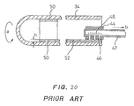
- FIG. 20 shows a conventional method of forming the inner electrode 36 within the oxygen sensor 32 using a nozzle tube 42 .
- the nozzle tube 42 is made of a hollow cylindrical member with a closed end and has installed thereon a hollow cylindrical nozzle head 44 in which outlet holes 46 are formed.
- the nozzle tube 42 is inserted into the interior of the ceramic body 34 .
- the nozzle head 44 is held at an interval h away from the inner surface of the ceramic body 34 .
- a noble metal paste is fed to the nozzle tube 42 under a given pressure and emitted from the outlet holes 46 .
- the ceramic body 34 is turned by one cycle in a direction a, thereby forming a paste-like annular layer 50 having a thickness of h on the inner surface of the ceramic body 34
- the nozzle tube 42 is withdrawn from the ceramic body 34 to a direction b to form a paste-like lead 52 extending from an edge of the annular layer 50 .
- the ceramic body 34 is dried and burned at approximately 1000° C., so that all organic substances are removed by heat treatment from the annular layer 50 and the lead 52 . Only metallic components are finally left on the inner surface of the ceramic body 34 , thereby forming the inner electrode 36 and the lead 38 , as shown in FIG. 15.
- the performance of the oxygen sensor 32 usually depends upon the compactness and the thickness of the electrodes 36 and 40 . After dried and burned, the paste film (i.e., the annular layer 50 and the lead 52 ) is decreased in thickness. It is, therefore, necessary to determine the thickness h of the paste film which compensates for the decrease in thickness.
- An organic solvent contained in the paste usually evaporates while being left as it is. Components of the paste change with time. Thus, even if the paste film has initially a desired thickness, an error in thickness of the electrode 36 and the lead 38 may arise.
- the thickness of the paste film depend directly upon the interval h between the nozzle head 44 and the inner surface of the ceramic body 34 . Typical adjustment of the interval h is achieved mechanically using the reading on a micrometer and thus quite inconvenient. Further, the amount of the paste supplied to the nozzle tube 42 depends upon the feed pressure and is difficult to adjust.
- the paste contains a large quantity of noble metal. If the paste solidifies within the nozzle tube 42 or a dispenser in which the paste is stored, it will cause the noble metal to go to waste. Particularly, if the paste solidifies within the nozzle tube 42 , it will be difficult to feed the paste additionally into the nozzle tube 42 . In the worst case, it becomes necessary to replace the nozzle tube 42 .
- an active liquid applicator designed to coat a surface of an electronic part such as an oxygen sensor with an active liquid to form a thin active film for making an electrode or lead wire.
- the active liquid applicator comprises: (a) dispensor storing therein the active liquid; (b) a nozzle tube connected to the dispenser; (c) a nozzle head provided on an end of the nozzle tube for applying the active liquid on a surface of an electronic part for forming an electrode; (d) a permeable member disposed within the nozzle tube; (e) a first mechanism working to make a contact between the nozzle head and the surface of the electronic part; and (f) a second mechanism working to move the nozzle head and the electronic part relative to each other while keeping the contact therebetween to coat a preselected portion of the surface of the electronic part with the active liquid.
- the permeable member has a length with first and a second end. The first end is connected to the nozzle head, while the second end is exposed to the active
- the length of the permeable member is at least five times longer than a diameter of the nozzle tube for ensuring uniformity of the coating on the electronic part.
- the dispensor is stood vertically.
- the permeable member works to produce capillary attraction of the active liquid thereinto to feed the active liquid to the nozzle head for applying the active liquid to the preselected portion of the surface of the electronic part.
- the electronic part includes a hollow cylinder.
- the first mechanism works to place the nozzle head within the hollow cylinder in contact with an inner surface of the hollow cylinder for coating the portion defined on the inner surface of the hollow cylinder with the active liquid.
- the electronic parts may be an oxygen sensor including a cup-shaped hollow cylindrical solid electrolyte body which defines a reference gas chamber therein.
- the first mechanism works to place the nozzle head within the reference gas chamber in contact with an inner side surface of the solid electrolyte body for coating a portion of the inner side surface with the active liquid to form the electrode on the portion of the inner side surface.
- the permeable member is preferably made of one of felt, fiber, and porous material.
- FIG. 1 is a front view which shows an active liquid applicator according to the invention
- FIG. 2 is a longitudinal sectional view which shows a nozzle tube inserted into an electronic part
- FIG. 3 is a longitudinal sectional view which shows a dispenser body in which an active liquid is stored and a nozzle tube connected to the dispenser body;
- FIG. 4 is a partially sectional view shows a process of coating an inner peripheral surface of an electronic part 4 with an active liquid emitted from a nozzle head;
- FIG. 5 is a sectional view taken along the line A-A in FIG. 4;
- FIG. 6 is a partially enlarged view of FIG. 5;
- FIG. 7 is a partially sectional view which illustrates a process of forming an active strip film on an inner peripheral surface of an electronic part which works as an electrical lead wire;
- FIG. 8 is a partially sectional view which shows a process of coating an inner bottom surface of an electronic part with an active liquid
- FIG. 9 is a partial cutaway view of FIG. 8;
- FIG. 10 is a partially sectional view which shows a process of forming an active film on an inner surface of an electronic part with an inner shoulder
- FIG. 11 is a partial cutaway view which illustrates an annular active film and an active strip film formed on an inner surface of an electronic part in the process of FIG. 10;
- FIG. 12 is a sectional view which shows a modification of a nozzle head
- FIG. 13 is a sectional view which shows a modification of a permeable member fitted in a nozzle tube
- FIG. 14 is a sectional view which shows the second modification of a permeable member fitted in a nozzle tube
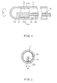
- FIG. 15 is a partially cutaway view illustrating an oxygen sensor to be coated with an active liquid by the active liquid applicator shown in FIG. 1;
- FIG. 16 is a perspective view which shows an external appearance of an oxygen sensor
- FIG. 17( a ) is a longitudinal sectional view of FIG. 16;
- FIG. 17( b ) is a longitudinal direction view taken from an angular direction different from that in FIG. 17( a );
- FIG. 17( c ) is transverse sectional view of FIG. 17( a );
- FIG. 18( a ) is a longitudinal sectional view which shows a modification of an electrode pattern formed in an oxygen sensor
- FIG. 18( b ) is a transverse sectional view of FIG. 18( a );
- FIG. 19( a ) is a longitudinal sectional view which shows the second modification of an electrode pattern formed in an oxygen sensor
- FIG. 19( b ) is a transverse sectional view of FIG. 19( a );
- FIG. 20 is a partially sectional view which shows a ceramic body of an oxygen sensor in which an inner surface is coated with an active paste by a conventional applicator.
- the inventors of this application studied an improved method of forming an electrode instead of a conventional paste applying method and came to the conclusion that it is the best way to form the electrode using an active film and electroless plating techniques.
- the inventors made a device, as discussed below, designed to form such an active film.
- the active film is a film formed by coating a selected area of a surface of an object on which an electrode is to be formed with an active liquid (i.e., an active catalyst liquid).
- the active catalyst is an active metal such as platinum.
- the active liquid is a solution containing a noble metal compound and, for example, prepared by dispersing organic noble metal compounds in an organic solvent.
- the active liquid is applied cover a selected portion of a surface of an electronic part to form the active film. After dried, the active film is burned at, for example, 600° C., thereby causing all organic components to be removed from the active film. Thus, resulting in formation of an active metal film.
- the active metal film has a structure in which active metal nuclei are dispersed like islands. It is advisable that the active metal nuclei be as fine as possible and dispersed to be uniform.
- the electronic part on which the active metal film is formed is immersed in an electroless plating liquid.
- Metal is precipitated on the active metal nuclei, so that the discrete active metal nuclei are joined to each other, thereby forming a thin film.
- Metal is further precipitated to increase the thickness of the thin film.
- the thickness of the metal film depends upon the metal concentration of the electroless plating liquid, a plating time, and the temperature of the plating bus, et al.
- the metal film forms an electrode film.
- the control of thickness of the electrode film may be performed at a stage of the electroless plating. This provides for simple and accurate adjustment of the thickness of the electrode film comparatively.
- the electrode film is formed only on the active film.
- the result of formation of the active film and compactness of the active metal film affect the electroless plating performed at a following stage.
- the active film is a prefilm of the electrode film, therefore, a measure of beauty of shape of the prefilm impinges on the configuration of the electrode film.
- the invention relates to an active liquid applicator used to form the active film, as described above, on an electronic part.
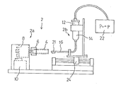
- FIG. 1 shows an active liquid applicator 2 according to the invention which is an improvement on a uniformly paste applying device as disclosed in International Patent Publication No. WO99/62644, disclosure of which is incorporated herein by reference.
- the active liquid applicator 2 is of a horizontal type in which an electronic parts-holding device 2 a and an active liquid dispenser 2 b are joined together horizontally.
- the device 2 a and the dispenser 2 b may alternatively be laid vertically.
- the electronic parts-holding device 2 a consists of a parts holder 6 , a rotary unit 8 , and a height adjuster 10 .
- the parts holder 6 is designed to hold a hollow cylindrical electronic part 4 .
- the rotary unit 8 works to turn the parts holder 6 .
- the height adjuster 10 works to move the rotary unit 8 vertically and holds it at a desired height.
- the active liquid dispenser 2 b consists of a dispenser body (i.e., a container) 12 , a pump 22 , a nozzle tube 16 , a painting head 21 , and a slider 24 .
- the dispenser body 12 stores therein an active liquid 14 which is pressurized and fed by the pump 22 to the nozzle tube 16 .
- the painting head 21 is installed on a tip of the nozzle tube 16 and works to emit the active liquid 14 .
- the slider 24 is designed to move laterally, as viewed in the drawing, to displace the painting head 21 into and out of the electronic part 4 .
- FIG. 2 is a longitudinal sectional view which shows the electronic part 4 , as illustrated as a solid electrolyte body of an oxygen sensor, into which the painting head 21 is inserted.
- the electronic part 4 is turned in directions A by the rotary unit 8 .
- the electronic part 4 is moved up and down in directions C by the height adjuster 10 .
- the painting head 21 and the nozzle tube 16 are moved horizontally in directions B by the slider 24 . These movements may be achieved simultaneously or separately.
- FIG. 3 is a longitudinal sectional view which shows the dispenser body 12 , the nozzle tube 16 , and the painting head 21 of the active liquid dispenser 2 b .
- the active liquid 14 is stored.
- the nozzle tube 16 is bent to an L-shape and joined to the bottom of the dispenser body 12 .
- a permeable member 18 is disposed which is made of an osmotic material working as a capillary tube to produce capillary attraction of the active liquid 14 thereinto and feed it to the painting head 21 .
- the permeable member 18 consist of a liquid sucking end 19 , a liquid feeding tube 20 , and the painting head 21 .
- the liquid sucking end 19 is inserted into the dispenser body 12 and works to suck in the active liquid 14 .
- the liquid feeding tube 20 works to feed the active liquid 14 through the capillarity.
- the painting head 21 emits the active liquid 14 fed from the liquid feeding tube 20 .
- the liquid sucking end 19 of the permeable member 20 is illustrated as extending into the dispenser body 12 , but may be located inside the nozzle tube 16 .
- the length L of a permeable portion of the permeable member 18 i.e., the distance between the liquid sucking end 19 and a downstream end of the permeable member 18
- L>Ln the distance between the liquid sucking end 19 and a downstream end of the permeable member 18
- R the seepage force or capillary attraction of the active liquid 14 into the permeable member 18 depends upon L/R.
- the permeable member 18 may be, as described above, made of any material exhibiting the capillarity action.
- a permeable material typically used as a tip of a marking pen is preferable.
- a soft felt pen material made of wool, synthetic fiber, and thermally weldable fiber, a similar material to which resin is also added for improving the durability thereof a synthetic fiber material formed by bonding synthetic fibers made of acrylic, polyester, and nylon using resin to increase the mechanical strength thereof, or other fiber pen materials may be employed.
- a plastic pen material may also be employed which has formed therein interconnecting holes producing capillary attraction of the active liquid 14 thereinto.
- copolymer or homopolymer such as polyacetal resin having formed therein many interconnecting cavities exhibiting the capillary action may be used.
- a porous material such as sponge may also be used.
- the painting head 21 of the permeable member 18 is shaped like a pen tip suitable for applying the active liquid 14 to the surface of the electronic part 4 .
- the painting head 21 has a curved portion 21 a and a straight portion 21 b .
- the curved portion 21 a is shaped for coating a curved wall (i.e. the bottom) of the electronic part 4 with the active liquid 14 .
- the straight portion 21 b is shaped for coating a straight wall (i.e., an inner side wall) of the electronic part 4 with the active liquid 14 .
- the installation of the permeable member 18 in the nozzle tube 16 is achieved by inserting the permeable member 18 into the nozzle tube 16 extending straight and bending the nozzle tube 16 to the L-shape.
- the active liquid 21 is liquid having a low viscosity which is made of a metal compound containing an active metal such as platinum.
- the active liquid 21 may be made by dispersing a metal organic compound such as platinum balsam sulfide or a metal inorganic compound such as platinum chloride in an organic solvent.
- the active liquid 14 unlike paste, has a lower viscosity and capable of burbling, so that it is less susceptible to solidification within the dispenser body 12 as well as the permeable member 18 . This enables a desired amount of the active liquid 14 to be emitted from the painting head 21 at all times.
- the paste as described in the introductory part of this application, is apt to solidify within the dispenser body 12 or adhere to other parts, so that the noble metal contained in the paste runs to waste as well as the paste itself.
- the active liquid 14 used in this embodiment is less susceptible to solidification within the dispenser body 12 and adhesion to other parts, thus eliminating the above problem.
- the painting head 21 is always wet with the active liquid 14 by the capillary action thereof, but it is difficult to supply a required amount of the active liquid 14 to the painting head 21 at all times only by the capillary attraction developed by the permeable member 18 .
- the pump 22 is turned on to feed the active liquid 14 to the painting head 21 under a set pressure.
- FIG. 4 shows a process of coating an inner side surface 4 a of the electronic part 4 with the active liquid 14 .
- the height adjuster 10 adjusts the height of the electronic part 4 to place the straight portion 21 b of the painting head 21 in contact with the inner side surface 4 a of the electronic part 4 .
- the slider 24 is actuated to advance the painting head 21 to a required location within the electronic part 4 .
- the straight portion 21 b of the painting head 21 When the straight portion 21 b of the painting head 21 is placed in contact with the inner side surface 4 a of the electronic part 4 , it will cause the active liquid 14 to be transferred from the painting head 21 to the inner side surface 4 a to form a thin coat of the active liquid 14 on the inner side surface 4 a .
- the rotary unit 8 turns the electronic part 4 one cycle in a direction a while keeping the positional relation between the painting head 21 and the electronic part 4 as it is, thereby forming an annular active film 25 over 360° on the inner side surface 4 a.
- FIG. 5 is a sectional view taken along the line A-A in FIG. 4. If the width of the painting head 21 is defined as W. and the width of the coat of the active liquid 14 on the inner side surface 4 a is defined as w, then a condition of W ⁇ w is usually met. The greater the permeability of the active liquid 14 , the greater the width w of the coat of the active liquid 14 than the width W of the painting head 21 . It is, thus, possible to estimate a coating efficiency as a function of a difference between w and W. We performed tests, as described later, using several samples to measure the difference w and Wand determined that when the value of w-W is 2 mm or less, a coating condition is acceptable (O), and when it is more than 2 mm, the coating condition is unacceptable (X).
- FIG. 6 is a partially enlarged view of FIG. 5. It is advisable that the painting head 21 be placed substantially in contact with the electronic part 4 , and the radius of curvature of an outer surface 21 d of the painting head 21 be substantially equal to that of the inner side surface 4 a of the electronic part 4 . However, if it is possible to keep a clearance between the outer surface 21 d of the painting head 21 and the inner side surface 4 a of the electronic part 4 very small, the outer surface 21 d of the painting head 21 needs not always be curved.
- FIG. 7 illustrates a process of forming an active linear film on the inner side surface of the electronic part 4 which works as an electrical lead.
- the painting head 21 is withdrawn by the slider 24 straight from a position, as illustrated in FIG. 4, in a direction b, thereby forming the active strip film 26 on the inner side surface of the electronic part 4 which extends from an edge of the annular active film 25 .
- the active strip film 26 has the width w which is defined as a function of the width W of the painting head 21 .
- the annular active film 25 and the active strip film 26 are subjected to the electroless plating to complete the inner electrode 36 and the inner electrode lead 38 , as shown in FIG. 15.
- FIG. 8 shows a process of coating an inner bottom surface 4 b of the electronic part 4 with the active liquid 14 .
- the inner electrode which covers the inner bottom surface 4 b is preferably formed in terms of a sensing efficiency.
- the curved portion 21 a of the painting head 21 is contoured to conform with the contour of the inner bottom surface 4 b of the electronic part 4 .
- the inner side surface 4 a of the electronic part 4 is brought into contact with the straight portion 21 b of the painting head 21 .
- the painting head 21 is advanced by the slider 24 until it reaches the inner bottom surface 4 b .
- the electronic part 4 is rotated one cycle in the direction a to coat the inner bottom surface 4 b with the active liquid 14 , thereby forming a single cup-shaped active film which includes the annular active film 25 identical with the one shown in FIG. 4 and an active bottom film 25 a .
- the painting head 21 is withdrawn by the slider 24 straight to form an active strip film identical with the strip 26 in FIG. 7.
- FIG. 9 is a partial cutaway view of FIG. 8 which illustrates the annular active film 25 , the active bottom film 25 a , and the active strip film 26 formed on the inner surface of the electronic part 4 .
- the illustrated electronic part 4 is burned at 400 to 600° C. to remove organic substances from the films 25 , 25 a and 16 , thereby forming an active metal film.
- the active metal film is subjected to the electroless plating using, for example, platinum to form an inner electrode with a lead within the electronic part 4 .
- FIG. 10 shows a process of forming an active film on an inner surface of an electronic part 4 with an inner shoulder.
- the nozzle head 2 used in this process has a flat end 21 c extending perpendicular to the length of the nozzle tube 16 instead of the curved portion 21 a.
- the inner side surface 4 a of the electronic part 4 is, like the above, brought into contact with the straight portion 21 b of the painting head 21 .
- the electronic part 4 is rotated one cycle in the direction a to coat the inner side surface 4 a with the active liquid 14 , thereby forming the annular active film 25 .
- the painting head 21 is withdrawn by the slider 24 in the direction b.
- FIG. 11 is a partial cutaway view which illustrates the annular active film 25 and the active strip film 26 formed on the inner surface of the electronic part 4 in the process of FIG. 10.
- the painting head 21 is, as described above, withdrawn.
- the electronic part 4 is lifted up by the height adjuster 10 to have the flat end 21 c slide on the inner shoulder 26 a , thereby forming a vertical active strip film 26 a that is a portion of the active strip film 26 .
- the painting head 21 is further withdrawn to complete the active strip film 26 .
- the active film made up of the annular active film 25 and the active strip film 26 including the vertical active strip film 26 a is formed on the inner side surface 4 a of the electronic part 4 .
- the electronic part 4 is burned at 400 to 600° C. to remove organic substances from the films 25 and 16 , thereby forming an active metal film.
- the active metal film is subjected to the electroless plating using, for example, platinum to form an inner electrode with a lead within the electronic part 4 .
- the active metal film is, as described above, the prefilm made only by an active metal and has preferably a thickness of, for example, about 1 ⁇ m.
- the electronic part 4 is immersed in an electroless plating bus to precipitate the active metal on the active metal film, thereby forming the electrode film. Adjustment of the thickness of the electrode film may be accomplished by controlling the concentration and temperature of an electroless plating liquid and a plating time.
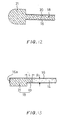
- FIG. 12 is a sectional view which shows a modification of the painting head 21 .
- the painting head 21 has a domed tip which is slightly smaller in size than the inner bottom surface 4 b of the electronic part 4 .
- the domed tip of the painting head 21 is less susceptible to deformation when the painting head 21 collides with any object during operation of the active liquid applicator 2 and exhibits a required degree of durability.
- the active bottom film 25 a and the annular active film 25 are formed simultaneously by placing the domed tip of the painting head 21 in contact with the inner bottom surface 4 b of the electronic part 4 and turning the electronic part 4 one cycle.
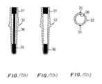
- FIG. 13 is a sectional view which shows a modification of the permeable member 18 which is much shorter than the one shown in FIG. 3.
- the liquid sucking end 19 of the permeable member 18 is located within the nozzle tube 16 and also works as the liquid feeding tube 20 as shown in FIG. 3.
- the nozzle tube 16 has a nozzle holder 16 a which avoids dislodgement of the permeable member 18 (i.e., the painting head 21 ) from the nozzle tube 16 .
- the active liquid 14 is in the vicinity of the tip of the nozzle tube 16 and permeates the painting head 21 through the liquid sucking end 19 .
- FIG. 14 is a sectional view which shows the second modification of the permeable member 18 .
- the liquid sucking end 19 of the permeable member 18 is located at the middle of the nozzle tube 16 .
- the table shows that the coating condition changes depending upon of a ratio of the length L of the permeable member 18 to the inner diameter R of the nozzle tube 16 ; namely L/R.
- L/R is preferably more than or equal to five (5), and more preferably more than or equal to ten (10), and that the active liquid 14 has a lower viscosity so that it may easily permeate the permeable member 18 , thereby resulting in a difficulty in controlling the amount of the active liquid 14 outputted from the painting head 21 , which may lead to irregularity of the coatings when L/R is less than five (5).
- FIG. 15 is, as already described, a partially cutaway view illustrating the oxygen sensor 32 installed in a combustion system of automotive engines.
- the oxygen sensor 32 is made up of the cup-shaped hollow cylindrical ceramic body 34 made of a solid electrolyte, the inner electrode 36 , and the outer electrode 40 .
- the inner electrode 36 connects with the inner lead 38 which is to be joined to an external circuit (not shown).
- a selected area of the outer wall of the ceramic body 34 is first coated in a desired outer electrode pattern with an active paste by transfer techniques employing a rolled pad.
- the active paste contains a noble metal compound for forming a noble metal nucleus.
- the coating on the ceramic body 34 is heated to dry organic solvent contained in the active paste.
- the formation of the inner electrode 36 is achieved using the active liquid applicator 2 as shown in FIGS. 1 and 3.
- the active liquid 14 containing a noble metal compound is applied to the inner surface of the ceramic body 34 in a desired inner electrode pattern and heated to dry the organic solvent.
- the ceramic body 34 is further heated at 400 to 600° C. to remove a binder contained in the coating and decompose the noble metal compound to form a noble metal nucleus on the coating. This burning also servers to remove the organic solvent from the coating on the outer wall of the ceramic body 34 , thereby completing the outer electrode 40 .
- the noble metal nucleus formed on the inner wall of the ceramic body 34 is subjected to the electroless plating to complete the inner electrode 36 .
- the noble metal nucleus and the plated coating are preferably made of platinum, but may be made of Pd, Au, or Rh. Of course, the noble metal nucleus and the plated coating may be made different materials.
- FIG. 16 shows a modification of the oxygen sensor 32 .
- the outer electrode 40 is a gas measurement electrode which is exposed to exhaust emissions of an automotive engine and works to output a signal to an external circuit through the outer lead 39 .
- Examples of the oxygen sensor 32 as will be discussed below, are all identical in external appearance with the one shown in FIG. 16.
- FIGS. 17 ( a ) to 17 ( c ) show an electrode pattern which may be formed within in the oxygen sensor of FIG. 16.
- FIG. 17( a ) is a longitudinal sectional view of FIG. 16 and illustrates the inner electrode 36 joined to an inner electrical terminal 37 through the inner lead 38 .
- FIG. 17( b ) is a longitudinal sectional view of FIG. 16 as taken from an angular direction different from that in FIG. 17( a ) in which the inner lead 38 is invisible.
- FIG. 17( c ) is a transverse sectional view which show the two outer leads 39 and the single inner lead 38 are formed on the outer and inner walls of the oxygen sensor 32 .
- FIGS. 18 ( a ) and 18 ( b ) show a modification of the oxygen sensor 32 .
- Two inner leads 38 are, as clearly shown in FIG. 18( b ), formed on the inner wall of the oxygen sensor 32 .
- FIGS. 19 ( a ) and 19 ( b ) show the second modification of the oxygen sensor 32 .
- the inner leads 38 are shifted 90° from the outer leads 39 in a circumferential direction of the oxygen sensor 32 .
- the inner electrical terminal 37 is not formed.
- An upper end, as viewed in FIG. 19( a ), of each of the inner leads 38 works as an electrical terminal.
- the active liquid applicator 2 may be of a vertical type in which the active liquid dispenser 2 b is laid on the electronic parts-holding device 2 a vertically.
- the electronic part 4 is stood vertically with an opening thereof oriented upward.
- the nozzle tube 16 is suspended vertically from the dispenser body 14 with the painting head 21 oriented downward.
- the slider 24 works to move the nozzle tube 16 vertically to insert the painting head 21 into the electronic part 4 .
- the rotary unit 8 turns the electronic part 4 to coat the inner wall of the electronic part 4 with the active liquid 14 .
- the vertical movement of the nozzle tube 16 and the rotational movement of the electronic part 4 form the annular active film 25 and the active strip film 26 on the inner wall of the electronic part 4 .
- the active liquid dispenser 2 b and the electronic parts-holding device 2 a may alternatively be disposed diagonally.
- the active liquid dispenser 2 b is located preferably above the electronic parts-holding device 2 a because the painting head 21 is well wet with the active liquid 14 with aid of the capillary action of the permeable member 18 , but a positional relation between the active liquid dispenser 2 b and the electronic parts-holding device 2 a may be changed as required.
Abstract
Description
- 1. Technical Field of the Invention
- The present invention relates generally to an active liquid applicator suitable for coating a surface of an electronic part with an active liquid to form an active film.
- 2. Background Art
- With development of electronic parts technology, electrodes of various electronic parts such as semiconductors have become formed by a noble metal such as platinum. Such electrodes are typically made using a noble metal paste. The noble metal paste is a semi-fluid substance which has viscosity and is formed by dispersing an organic noble metal complex within an organic solvent together with resin.
- The formation of a metallic lead and a metallic electrode on the surface of electronic parts is achieved by applying the noble metal paste to a selected area of the electronic parts to form an electrode film and drying and burning it at a given temperature to remove all organic substances therefrom, leaving only metal as a metallic film. As an example of the electronic parts, an oxygen sensor will be described below.
- FIG. 15 is a partially cutaway view which shows an
oxygen sensor 32 installed in a combustion system of automotive engines. Theoxygen sensor 32 is made up of a cup-shaped hollow cylindricalceramic body 34 made of a solid electrolyte, areference electrode 36 formed on an inner surface of theceramic body 34, and ameasurement electrode 40 formed on an outer surface of theceramic body 34. Thereference electrode 36 is exposed to a reference gas. Themeasurement electrode 40 is exposed to a gas to be measured. In order to use terminology in common with typical electronic parts throughout the present specification, the reference electrode and measurement electrode will be referred to as an inner electrode and an outer electrode, respectively. Theinner electrode 36 has aninner lead 38. - The
oxygen sensor 32 is installed in an exhaust pipe connected to the engine. Theouter electrode 40 is exposed to exhaust gasses. Theinner electrode 36 is exposed to the air. Between theelectrodes - FIG. 20 shows a conventional method of forming the
inner electrode 36 within theoxygen sensor 32 using anozzle tube 42. - The
nozzle tube 42 is made of a hollow cylindrical member with a closed end and has installed thereon a hollowcylindrical nozzle head 44 in whichoutlet holes 46 are formed. - The
nozzle tube 42 is inserted into the interior of theceramic body 34. Thenozzle head 44 is held at an interval h away from the inner surface of theceramic body 34. A noble metal paste is fed to thenozzle tube 42 under a given pressure and emitted from theoutlet holes 46. Simultaneously, theceramic body 34 is turned by one cycle in a direction a, thereby forming a paste-likeannular layer 50 having a thickness of h on the inner surface of theceramic body 34 - After the formation of the paste-like
annular layer 50, thenozzle tube 42 is withdrawn from theceramic body 34 to a direction b to form a paste-like lead 52 extending from an edge of theannular layer 50. - The
ceramic body 34 is dried and burned at approximately 1000° C., so that all organic substances are removed by heat treatment from theannular layer 50 and thelead 52. Only metallic components are finally left on the inner surface of theceramic body 34, thereby forming theinner electrode 36 and thelead 38, as shown in FIG. 15. - The performance of the
oxygen sensor 32 usually depends upon the compactness and the thickness of theelectrodes annular layer 50 and the lead 52) is decreased in thickness. It is, therefore, necessary to determine the thickness h of the paste film which compensates for the decrease in thickness. - An organic solvent contained in the paste usually evaporates while being left as it is. Components of the paste change with time. Thus, even if the paste film has initially a desired thickness, an error in thickness of the
electrode 36 and thelead 38 may arise. - The thickness of the paste film depend directly upon the interval h between the
nozzle head 44 and the inner surface of theceramic body 34. Typical adjustment of the interval h is achieved mechanically using the reading on a micrometer and thus quite inconvenient. Further, the amount of the paste supplied to thenozzle tube 42 depends upon the feed pressure and is difficult to adjust. - The paste contains a large quantity of noble metal. If the paste solidifies within the
nozzle tube 42 or a dispenser in which the paste is stored, it will cause the noble metal to go to waste. Particularly, if the paste solidifies within thenozzle tube 42, it will be difficult to feed the paste additionally into thenozzle tube 42. In the worst case, it becomes necessary to replace thenozzle tube 42. - It is therefore a principal object of the invention to avoid the disadvantages of the prior art.
- It is another object of the invention to provide an active liquid applicator designed to coat a surface of an electronic part such as an oxygen sensor with an active liquid to form a thin active film, thereby permitting the active film to be subjected to electroless plating to form a metal film thereon which has the thickness controllable with high accuracy.
- According to one aspect of the invention, there is provided an active liquid applicator designed to coat a surface of an electronic part such as an oxygen sensor with an active liquid to form a thin active film for making an electrode or lead wire. The active liquid applicator comprises: (a) dispensor storing therein the active liquid; (b) a nozzle tube connected to the dispenser; (c) a nozzle head provided on an end of the nozzle tube for applying the active liquid on a surface of an electronic part for forming an electrode; (d) a permeable member disposed within the nozzle tube; (e) a first mechanism working to make a contact between the nozzle head and the surface of the electronic part; and (f) a second mechanism working to move the nozzle head and the electronic part relative to each other while keeping the contact therebetween to coat a preselected portion of the surface of the electronic part with the active liquid. The permeable member has a length with first and a second end. The first end is connected to the nozzle head, while the second end is exposed to the active liquid. The permeable member works to feed the active liquid from the dispensor to the nozzle head.
- In the preferred mode of the invention, the length of the permeable member is at least five times longer than a diameter of the nozzle tube for ensuring uniformity of the coating on the electronic part.
- The dispensor is stood vertically. The permeable member works to produce capillary attraction of the active liquid thereinto to feed the active liquid to the nozzle head for applying the active liquid to the preselected portion of the surface of the electronic part.
- The electronic part includes a hollow cylinder. The first mechanism works to place the nozzle head within the hollow cylinder in contact with an inner surface of the hollow cylinder for coating the portion defined on the inner surface of the hollow cylinder with the active liquid.
- The electronic parts may be an oxygen sensor including a cup-shaped hollow cylindrical solid electrolyte body which defines a reference gas chamber therein. In this case, the first mechanism works to place the nozzle head within the reference gas chamber in contact with an inner side surface of the solid electrolyte body for coating a portion of the inner side surface with the active liquid to form the electrode on the portion of the inner side surface.
- The permeable member is preferably made of one of felt, fiber, and porous material.
- The present invention will be understood more fully from the detailed description given hereinbelow and from the accompanying drawings of the preferred embodiments of the invention, which, however, should not be taken to limit the invention to the specific embodiments but are for the purpose of explanation and understanding only.
- In the drawings:
- FIG. 1 is a front view which shows an active liquid applicator according to the invention;
- FIG. 2 is a longitudinal sectional view which shows a nozzle tube inserted into an electronic part;
- FIG. 3 is a longitudinal sectional view which shows a dispenser body in which an active liquid is stored and a nozzle tube connected to the dispenser body;
- FIG. 4 is a partially sectional view shows a process of coating an inner peripheral surface of an
electronic part 4 with an active liquid emitted from a nozzle head; - FIG. 5 is a sectional view taken along the line A-A in FIG. 4;
- FIG. 6 is a partially enlarged view of FIG. 5;
- FIG. 7 is a partially sectional view which illustrates a process of forming an active strip film on an inner peripheral surface of an electronic part which works as an electrical lead wire;
- FIG. 8 is a partially sectional view which shows a process of coating an inner bottom surface of an electronic part with an active liquid;
- FIG. 9 is a partial cutaway view of FIG. 8;
- FIG. 10 is a partially sectional view which shows a process of forming an active film on an inner surface of an electronic part with an inner shoulder;
- FIG. 11 is a partial cutaway view which illustrates an annular active film and an active strip film formed on an inner surface of an electronic part in the process of FIG. 10;
- FIG. 12 is a sectional view which shows a modification of a nozzle head;
- FIG. 13 is a sectional view which shows a modification of a permeable member fitted in a nozzle tube;
- FIG. 14 is a sectional view which shows the second modification of a permeable member fitted in a nozzle tube;
- FIG. 15 is a partially cutaway view illustrating an oxygen sensor to be coated with an active liquid by the active liquid applicator shown in FIG. 1;
- FIG. 16 is a perspective view which shows an external appearance of an oxygen sensor;
- FIG. 17( a) is a longitudinal sectional view of FIG. 16;
- FIG. 17( b) is a longitudinal direction view taken from an angular direction different from that in FIG. 17(a);
- FIG. 17( c) is transverse sectional view of FIG. 17(a);
- FIG. 18( a) is a longitudinal sectional view which shows a modification of an electrode pattern formed in an oxygen sensor;
- FIG. 18( b) is a transverse sectional view of FIG. 18(a);
- FIG. 19( a) is a longitudinal sectional view which shows the second modification of an electrode pattern formed in an oxygen sensor;
- FIG. 19( b) is a transverse sectional view of FIG. 19(a); and
- FIG. 20 is a partially sectional view which shows a ceramic body of an oxygen sensor in which an inner surface is coated with an active paste by a conventional applicator.
- The inventors of this application studied an improved method of forming an electrode instead of a conventional paste applying method and came to the conclusion that it is the best way to form the electrode using an active film and electroless plating techniques. The inventors made a device, as discussed below, designed to form such an active film.
- The active film is a film formed by coating a selected area of a surface of an object on which an electrode is to be formed with an active liquid (i.e., an active catalyst liquid). The active catalyst is an active metal such as platinum. The active liquid is a solution containing a noble metal compound and, for example, prepared by dispersing organic noble metal compounds in an organic solvent.
- The active liquid is applied cover a selected portion of a surface of an electronic part to form the active film. After dried, the active film is burned at, for example, 600° C., thereby causing all organic components to be removed from the active film. Thus, resulting in formation of an active metal film. The active metal film has a structure in which active metal nuclei are dispersed like islands. It is advisable that the active metal nuclei be as fine as possible and dispersed to be uniform.
- Next, the electronic part on which the active metal film is formed is immersed in an electroless plating liquid. Metal is precipitated on the active metal nuclei, so that the discrete active metal nuclei are joined to each other, thereby forming a thin film. Metal is further precipitated to increase the thickness of the thin film. In this way, the metal is deposited continuously only on the surface of the active metal film. The thickness of the metal film depends upon the metal concentration of the electroless plating liquid, a plating time, and the temperature of the plating bus, et al. The metal film forms an electrode film. The control of thickness of the electrode film may be performed at a stage of the electroless plating. This provides for simple and accurate adjustment of the thickness of the electrode film comparatively.
- As apparent from the above discussion, the electrode film is formed only on the active film. The result of formation of the active film and compactness of the active metal film affect the electroless plating performed at a following stage. Specifically, the active film is a prefilm of the electrode film, therefore, a measure of beauty of shape of the prefilm impinges on the configuration of the electrode film. The invention relates to an active liquid applicator used to form the active film, as described above, on an electronic part.
- FIG. 1 shows an active
liquid applicator 2 according to the invention which is an improvement on a uniformly paste applying device as disclosed in International Patent Publication No. WO99/62644, disclosure of which is incorporated herein by reference. - The active
liquid applicator 2 is of a horizontal type in which an electronic parts-holdingdevice 2 a and an activeliquid dispenser 2 b are joined together horizontally. Of course, thedevice 2 a and thedispenser 2 b may alternatively be laid vertically. The electronic parts-holdingdevice 2 a consists of aparts holder 6, arotary unit 8, and aheight adjuster 10. Theparts holder 6 is designed to hold a hollow cylindricalelectronic part 4. Therotary unit 8 works to turn theparts holder 6. Theheight adjuster 10 works to move therotary unit 8 vertically and holds it at a desired height. - The active
liquid dispenser 2 b consists of a dispenser body (i.e., a container) 12, apump 22, anozzle tube 16, apainting head 21, and aslider 24. Thedispenser body 12 stores therein anactive liquid 14 which is pressurized and fed by thepump 22 to thenozzle tube 16. Thepainting head 21 is installed on a tip of thenozzle tube 16 and works to emit theactive liquid 14. Theslider 24 is designed to move laterally, as viewed in the drawing, to displace thepainting head 21 into and out of theelectronic part 4. - FIG. 2 is a longitudinal sectional view which shows the
electronic part 4, as illustrated as a solid electrolyte body of an oxygen sensor, into which thepainting head 21 is inserted. Theelectronic part 4 is turned in directions A by therotary unit 8. Theelectronic part 4 is moved up and down in directions C by theheight adjuster 10. Thepainting head 21 and thenozzle tube 16 are moved horizontally in directions B by theslider 24. These movements may be achieved simultaneously or separately. - FIG. 3 is a longitudinal sectional view which shows the
dispenser body 12, thenozzle tube 16, and thepainting head 21 of the activeliquid dispenser 2 b. Within thedispenser body 12, theactive liquid 14 is stored. Thenozzle tube 16 is bent to an L-shape and joined to the bottom of thedispenser body 12. Within thenozzle tube 16, apermeable member 18 is disposed which is made of an osmotic material working as a capillary tube to produce capillary attraction of theactive liquid 14 thereinto and feed it to thepainting head 21. Specifically, thepermeable member 18 consist of aliquid sucking end 19, aliquid feeding tube 20, and thepainting head 21. Theliquid sucking end 19 is inserted into thedispenser body 12 and works to suck in theactive liquid 14. Theliquid feeding tube 20 works to feed the active liquid 14 through the capillarity. Thepainting head 21 emits the active liquid 14 fed from theliquid feeding tube 20. - The
liquid sucking end 19 of thepermeable member 20 is illustrated as extending into thedispenser body 12, but may be located inside thenozzle tube 16. Specifically, the length L of a permeable portion of the permeable member 18 (i.e., the distance between the liquid suckingend 19 and a downstream end of the permeable member 18) may be either greater (i.e., L>Ln) or smaller (i.e., 0<L≦Ln) than the length Ln of thenozzle tube 16. When L≦Ln, theactive liquid 14 is also stored within thenozzle tube 16, but sucked by theliquid sucking end 19 into theliquid feeding tube 20 sufficiently. If the inner diameter of the nozzle tube 16 (i.e., the diameter of an inner wall of the nozzle tube 16) is defined as R, the seepage force or capillary attraction of the active liquid 14 into thepermeable member 18 depends upon L/R. - The
permeable member 18 may be, as described above, made of any material exhibiting the capillarity action. A permeable material typically used as a tip of a marking pen is preferable. For example, a soft felt pen material made of wool, synthetic fiber, and thermally weldable fiber, a similar material to which resin is also added for improving the durability thereof, a synthetic fiber material formed by bonding synthetic fibers made of acrylic, polyester, and nylon using resin to increase the mechanical strength thereof, or other fiber pen materials may be employed. Further, a plastic pen material may also be employed which has formed therein interconnecting holes producing capillary attraction of theactive liquid 14 thereinto. For example, copolymer or homopolymer such as polyacetal resin having formed therein many interconnecting cavities exhibiting the capillary action may be used. A porous material such as sponge may also be used. - The
painting head 21 of thepermeable member 18 is shaped like a pen tip suitable for applying the active liquid 14 to the surface of theelectronic part 4. Thepainting head 21 has acurved portion 21 a and astraight portion 21 b. Thecurved portion 21 a is shaped for coating a curved wall (i.e. the bottom) of theelectronic part 4 with theactive liquid 14. Thestraight portion 21 b is shaped for coating a straight wall (i.e., an inner side wall) of theelectronic part 4 with theactive liquid 14. - The installation of the
permeable member 18 in thenozzle tube 16 is achieved by inserting thepermeable member 18 into thenozzle tube 16 extending straight and bending thenozzle tube 16 to the L-shape. - The
active liquid 21 is liquid having a low viscosity which is made of a metal compound containing an active metal such as platinum. Theactive liquid 21 may be made by dispersing a metal organic compound such as platinum balsam sulfide or a metal inorganic compound such as platinum chloride in an organic solvent. - The inventors of this application have proposed in Japanese Patent First Publication No. 9-272996 an active liquid made by dispersing a noble metal organic complex such as bis(dibenzylideneacetone) noble metal or tris(dibenzylideneaceton) noble metal in an organic solvent, which may be used as the
active liquid 21. Disclosure of the publication is incorporated herein by reference. - The
active liquid 14, unlike paste, has a lower viscosity and capable of burbling, so that it is less susceptible to solidification within thedispenser body 12 as well as thepermeable member 18. This enables a desired amount of the active liquid 14 to be emitted from thepainting head 21 at all times. - The paste, as described in the introductory part of this application, is apt to solidify within the
dispenser body 12 or adhere to other parts, so that the noble metal contained in the paste runs to waste as well as the paste itself. The active liquid 14 used in this embodiment is less susceptible to solidification within thedispenser body 12 and adhesion to other parts, thus eliminating the above problem. - The
painting head 21 is always wet with theactive liquid 14 by the capillary action thereof, but it is difficult to supply a required amount of the active liquid 14 to thepainting head 21 at all times only by the capillary attraction developed by thepermeable member 18. Thus, when it is required to emit an amount of the active liquid 14 from thepainting head 21 exceeding the limit of the capillary attraction, thepump 22 is turned on to feed the active liquid 14 to thepainting head 21 under a set pressure. - FIG. 4 shows a process of coating an
inner side surface 4 a of theelectronic part 4 with theactive liquid 14. - First, the
height adjuster 10 adjusts the height of theelectronic part 4 to place thestraight portion 21 b of thepainting head 21 in contact with theinner side surface 4 a of theelectronic part 4. Next, theslider 24 is actuated to advance thepainting head 21 to a required location within theelectronic part 4. - When the
straight portion 21b of thepainting head 21 is placed in contact with theinner side surface 4 a of theelectronic part 4, it will cause the active liquid 14 to be transferred from thepainting head 21 to theinner side surface 4 a to form a thin coat of theactive liquid 14 on theinner side surface 4 a. Therotary unit 8 turns theelectronic part 4 one cycle in a direction a while keeping the positional relation between thepainting head 21 and theelectronic part 4 as it is, thereby forming an annularactive film 25 over 360° on theinner side surface 4 a. - FIG. 5 is a sectional view taken along the line A-A in FIG. 4. If the width of the
painting head 21 is defined as W. and the width of the coat of theactive liquid 14 on theinner side surface 4 a is defined as w, then a condition of W≦w is usually met. The greater the permeability of theactive liquid 14, the greater the width w of the coat of the active liquid 14 than the width W of thepainting head 21. It is, thus, possible to estimate a coating efficiency as a function of a difference between w and W. We performed tests, as described later, using several samples to measure the difference w and Wand determined that when the value of w-W is 2 mm or less, a coating condition is acceptable (O), and when it is more than 2 mm, the coating condition is unacceptable (X). - FIG. 6 is a partially enlarged view of FIG. 5. It is advisable that the
painting head 21 be placed substantially in contact with theelectronic part 4, and the radius of curvature of anouter surface 21 d of thepainting head 21 be substantially equal to that of theinner side surface 4 a of theelectronic part 4. However, if it is possible to keep a clearance between theouter surface 21 d of thepainting head 21 and theinner side surface 4a of theelectronic part 4 very small, theouter surface 21 d of thepainting head 21 needs not always be curved. - FIG. 7 illustrates a process of forming an active linear film on the inner side surface of the
electronic part 4 which works as an electrical lead. - The
painting head 21 is withdrawn by theslider 24 straight from a position, as illustrated in FIG. 4, in a direction b, thereby forming theactive strip film 26 on the inner side surface of theelectronic part 4 which extends from an edge of the annularactive film 25. Theactive strip film 26 has the width w which is defined as a function of the width W of thepainting head 21. Finally, the annularactive film 25 and theactive strip film 26 are subjected to the electroless plating to complete theinner electrode 36 and theinner electrode lead 38, as shown in FIG. 15. - FIG. 8 shows a process of coating an
inner bottom surface 4 b of theelectronic part 4 with theactive liquid 14. In a case where theelectronic part 4 is used as an oxygen sensor, the inner electrode which covers theinner bottom surface 4 b is preferably formed in terms of a sensing efficiency. In this embodiment, thecurved portion 21 a of thepainting head 21 is contoured to conform with the contour of theinner bottom surface 4 b of theelectronic part 4. - First, the
inner side surface 4 a of theelectronic part 4 is brought into contact with thestraight portion 21 b of thepainting head 21. Thepainting head 21 is advanced by theslider 24 until it reaches theinner bottom surface 4 b. Next, theelectronic part 4 is rotated one cycle in the direction a to coat theinner bottom surface 4 b with theactive liquid 14, thereby forming a single cup-shaped active film which includes the annularactive film 25 identical with the one shown in FIG. 4 and anactive bottom film 25 a. Subsequently, thepainting head 21 is withdrawn by theslider 24 straight to form an active strip film identical with thestrip 26 in FIG. 7. - FIG. 9 is a partial cutaway view of FIG. 8 which illustrates the annular
active film 25, theactive bottom film 25 a, and theactive strip film 26 formed on the inner surface of theelectronic part 4. - After dried, the illustrated
electronic part 4 is burned at 400 to 600° C. to remove organic substances from thefilms electronic part 4. - FIG. 10 shows a process of forming an active film on an inner surface of an
electronic part 4 with an inner shoulder. Thenozzle head 2 used in this process has aflat end 21 c extending perpendicular to the length of thenozzle tube 16 instead of thecurved portion 21 a. - First, the
inner side surface 4 a of theelectronic part 4 is, like the above, brought into contact with thestraight portion 21 b of thepainting head 21. Next, theelectronic part 4 is rotated one cycle in the direction a to coat theinner side surface 4 a with theactive liquid 14, thereby forming the annularactive film 25. Subsequently, thepainting head 21 is withdrawn by theslider 24 in the direction b. - FIG. 11 is a partial cutaway view which illustrates the annular
active film 25 and theactive strip film 26 formed on the inner surface of theelectronic part 4 in the process of FIG. 10. After the annularactive film 25 is formed, thepainting head 21 is, as described above, withdrawn. When theflat end 21 c of thepainting head 21 reaches above theinner shoulder 26 a, theelectronic part 4 is lifted up by theheight adjuster 10 to have theflat end 21 c slide on theinner shoulder 26 a, thereby forming a verticalactive strip film 26 a that is a portion of theactive strip film 26. Subsequently, thepainting head 21 is further withdrawn to complete theactive strip film 26. Specifically, the active film made up of the annularactive film 25 and theactive strip film 26 including the verticalactive strip film 26 a is formed on theinner side surface 4 a of theelectronic part 4. - After dried, the
electronic part 4 is burned at 400 to 600° C. to remove organic substances from thefilms electronic part 4. - The active metal film is, as described above, the prefilm made only by an active metal and has preferably a thickness of, for example, about 1 μm. After formation of the active metal film, the
electronic part 4 is immersed in an electroless plating bus to precipitate the active metal on the active metal film, thereby forming the electrode film. Adjustment of the thickness of the electrode film may be accomplished by controlling the concentration and temperature of an electroless plating liquid and a plating time. - FIG. 12 is a sectional view which shows a modification of the
painting head 21. Thepainting head 21 has a domed tip which is slightly smaller in size than theinner bottom surface 4 b of theelectronic part 4. The domed tip of thepainting head 21 is less susceptible to deformation when thepainting head 21 collides with any object during operation of the activeliquid applicator 2 and exhibits a required degree of durability. Theactive bottom film 25 a and the annularactive film 25 are formed simultaneously by placing the domed tip of thepainting head 21 in contact with theinner bottom surface 4 b of theelectronic part 4 and turning theelectronic part 4 one cycle. - FIG. 13 is a sectional view which shows a modification of the
permeable member 18 which is much shorter than the one shown in FIG. 3. Specifically, theliquid sucking end 19 of thepermeable member 18 is located within thenozzle tube 16 and also works as theliquid feeding tube 20 as shown in FIG. 3. Thenozzle tube 16 has anozzle holder 16 a which avoids dislodgement of the permeable member 18 (i.e., the painting head 21) from thenozzle tube 16. Theactive liquid 14 is in the vicinity of the tip of thenozzle tube 16 and permeates thepainting head 21 through theliquid sucking end 19. - FIG. 14 is a sectional view which shows the second modification of the
permeable member 18. Theliquid sucking end 19 of thepermeable member 18 is located at the middle of thenozzle tube 16. - We performed tests using samples of the
permeable member 18 to evaluate conditions of coatings of theactive liquid 14 on theelectronic part 4 for different values of the length L of thepermeable member 18 and the inner diameter R of thenozzle tube 16, and different materials of thepermeable member 18. As already described above, when the difference between the width W of thepainting head 21 and the width w of the coating of theactive liquid 14; namely, w-W is 2 mm or less, the coating condition is determined as being acceptable (O), and when it is more than 2 mm, the coating condition is determined as being unacceptable (X). The results of the tests are shown in the following table.TABLE Test Permeable Liquid feed Coating No. R (mm) L (mm) L/R material pressure condition 1 0.5 0 — felt not used X 2 0.5 5 10.0 felt not used ◯ 3 0.5 100 200.0 felt not used ◯ 4 1 0 — felt not used X 5 1 15 15.0 felt not used ◯ 6 1 50 50.0 felt not used ◯ 7 1 200 200.0 felt not used ◯ 8 1.5 0 — felt not used X 9 1.5 1.5 1.0 felt not used X 10 1.5 7.5 5.0 felt not used ◯ 11 1.5 10 6.7 felt not used ◯ 12 1.5 15 10.0 felt not used ◯ 13 1.5 30 20.0 felt not used ◯ 14 1.5 50 33.3 felt not used ◯ 15 1.5 100 66.7 felt not used ◯ 16 1.5 200 133.3 felt not used ◯ 17 1.5 400 266.7 felt used ◯ 18 1.5 400 266.7 felt not used ◯ 19 2 10 5.0 felt not used ◯ 20 2 50 25.0 felt not used ◯ 21 2 400 200.0 felt not used ◯ 22 2.5 50 20.0 felt not used ◯ 23 3 300 100.0 felt not used ◯ 24 1.5 10 6.7 fiber not used ◯ 25 1.5 30 20.0 fiber not used ◯ 26 1.5 200 133.3 fiber not used ◯ 27 1.5 30 20.0 porous rub. not used ◯ 28 1.5 200 133.3 porous rub. not used ◯ 29 1.5 200 133.3 porous rub. used ◯ 30 1.5 400 266.7 porous rub. used ◯ - The table shows that the coating condition changes depending upon of a ratio of the length L of the
permeable member 18 to the inner diameter R of thenozzle tube 16; namely L/R. We found that the coatings of theactive liquid 14 on theelectronic part 4 are acceptable when L/R is preferably more than or equal to five (5), and more preferably more than or equal to ten (10), and that theactive liquid 14 has a lower viscosity so that it may easily permeate thepermeable member 18, thereby resulting in a difficulty in controlling the amount of the active liquid 14 outputted from thepainting head 21, which may lead to irregularity of the coatings when L/R is less than five (5). - Even if L/R<5, it is possible to increase the viscosity of the
active liquid 14 and feed theactive liquid 14 under pressure, but if the length L of thepermeable member 18 is smaller, a difficulty is encountered in controlling the level of the pressure, thus requiring an expensive pressure controller. Alternatively, if L/R is greater such as in the test No. 18 in the above table, it results in lack of applied amount of theactive liquid 14, which may lead to formation of blurs on the coatings. In this case, it is preferable to feed theactive liquid 14 under pressure. Thepermeable member 18 in the test Nos. 29 and 30 is made of porous rubber which is somewhat less in pore than felt. It is, thus, preferable to feed theactive liquid 14 under pressure. - FIG. 15 is, as already described, a partially cutaway view illustrating the
oxygen sensor 32 installed in a combustion system of automotive engines. Theoxygen sensor 32 is made up of the cup-shaped hollow cylindricalceramic body 34 made of a solid electrolyte, theinner electrode 36, and theouter electrode 40. Theinner electrode 36 connects with theinner lead 38 which is to be joined to an external circuit (not shown). - In order to form the
outer electrode 40, a selected area of the outer wall of theceramic body 34 is first coated in a desired outer electrode pattern with an active paste by transfer techniques employing a rolled pad. The active paste contains a noble metal compound for forming a noble metal nucleus. The coating on theceramic body 34 is heated to dry organic solvent contained in the active paste. - Subsequently, the formation of the
inner electrode 36 is achieved using the activeliquid applicator 2 as shown in FIGS. 1 and 3. First, the active liquid 14 containing a noble metal compound is applied to the inner surface of theceramic body 34 in a desired inner electrode pattern and heated to dry the organic solvent. Theceramic body 34 is further heated at 400 to 600° C. to remove a binder contained in the coating and decompose the noble metal compound to form a noble metal nucleus on the coating. This burning also servers to remove the organic solvent from the coating on the outer wall of theceramic body 34, thereby completing theouter electrode 40. - Finally, the noble metal nucleus formed on the inner wall of the
ceramic body 34 is subjected to the electroless plating to complete theinner electrode 36. The noble metal nucleus and the plated coating are preferably made of platinum, but may be made of Pd, Au, or Rh. Of course, the noble metal nucleus and the plated coating may be made different materials. - FIG. 16 shows a modification of the
oxygen sensor 32. Theouter electrode 40 is a gas measurement electrode which is exposed to exhaust emissions of an automotive engine and works to output a signal to an external circuit through theouter lead 39. Examples of theoxygen sensor 32, as will be discussed below, are all identical in external appearance with the one shown in FIG. 16. - FIGS. 17(a) to 17(c) show an electrode pattern which may be formed within in the oxygen sensor of FIG. 16. FIG. 17(a) is a longitudinal sectional view of FIG. 16 and illustrates the
inner electrode 36 joined to an innerelectrical terminal 37 through theinner lead 38. FIG. 17(b) is a longitudinal sectional view of FIG. 16 as taken from an angular direction different from that in FIG. 17(a) in which theinner lead 38 is invisible. FIG. 17(c) is a transverse sectional view which show the twoouter leads 39 and the singleinner lead 38 are formed on the outer and inner walls of theoxygen sensor 32. - FIGS. 18(a) and 18(b) show a modification of the
oxygen sensor 32. Twoinner leads 38 are, as clearly shown in FIG. 18(b), formed on the inner wall of theoxygen sensor 32. - FIGS. 19(a) and 19(b) show the second modification of the
oxygen sensor 32. The inner leads 38 are shifted 90° from the outer leads 39 in a circumferential direction of theoxygen sensor 32. The innerelectrical terminal 37 is not formed. An upper end, as viewed in FIG. 19(a), of each of the inner leads 38 works as an electrical terminal. - While the present invention has been disclosed in terms of the preferred embodiments in order to facilitate better understanding thereof, it should be appreciated that the invention can be embodied in various ways without departing from the principle of the invention. Therefore, the invention should be understood to include all possible embodiments and modifications to the shown embodiments witch can be embodied without departing from the principle of the invention as set forth in the appended claims. For example, the active
liquid applicator 2 may be of a vertical type in which the activeliquid dispenser 2 b is laid on the electronic parts-holdingdevice 2 a vertically. In this case, theelectronic part 4 is stood vertically with an opening thereof oriented upward. Thenozzle tube 16 is suspended vertically from thedispenser body 14 with thepainting head 21 oriented downward. Theslider 24 works to move thenozzle tube 16 vertically to insert thepainting head 21 into theelectronic part 4. Therotary unit 8 turns theelectronic part 4 to coat the inner wall of theelectronic part 4 with theactive liquid 14. The vertical movement of thenozzle tube 16 and the rotational movement of theelectronic part 4 form the annularactive film 25 and theactive strip film 26 on the inner wall of theelectronic part 4. - The active
liquid dispenser 2 b and the electronic parts-holdingdevice 2 a may alternatively be disposed diagonally. In this case, the activeliquid dispenser 2 b is located preferably above the electronic parts-holdingdevice 2 a because thepainting head 21 is well wet with the active liquid 14 with aid of the capillary action of thepermeable member 18, but a positional relation between the activeliquid dispenser 2 b and the electronic parts-holdingdevice 2 a may be changed as required.
Claims (6)
Priority Applications (1)
| Application Number | Priority Date | Filing Date | Title |
|---|---|---|---|
| US11/273,090 US20060068095A1 (en) | 2002-04-17 | 2005-11-15 | Active liquid applicator for forming active film |
Applications Claiming Priority (2)
| Application Number | Priority Date | Filing Date | Title |
|---|---|---|---|
| JP2002114213A JP2003080153A (en) | 2001-06-27 | 2002-04-17 | Active liquid coating apparatus |
| JP2002-114213 | 2002-04-17 |
Related Child Applications (1)
| Application Number | Title | Priority Date | Filing Date |
|---|---|---|---|
| US11/273,090 Division US20060068095A1 (en) | 2002-04-17 | 2005-11-15 | Active liquid applicator for forming active film |
Publications (1)
| Publication Number | Publication Date |
|---|---|
| US20030196596A1 true US20030196596A1 (en) | 2003-10-23 |
Family
ID=28672635
Family Applications (2)
| Application Number | Title | Priority Date | Filing Date |
|---|---|---|---|
| US10/292,592 Abandoned US20030196596A1 (en) | 2002-04-17 | 2002-11-13 | Active liquid applicator for forming active film |
| US11/273,090 Abandoned US20060068095A1 (en) | 2002-04-17 | 2005-11-15 | Active liquid applicator for forming active film |
Family Applications After (1)
| Application Number | Title | Priority Date | Filing Date |
|---|---|---|---|
| US11/273,090 Abandoned US20060068095A1 (en) | 2002-04-17 | 2005-11-15 | Active liquid applicator for forming active film |
Country Status (2)
| Country | Link |
|---|---|
| US (2) | US20030196596A1 (en) |
| EP (1) | EP1354637B1 (en) |
Cited By (2)
| Publication number | Priority date | Publication date | Assignee | Title |
|---|---|---|---|---|
| US7563324B1 (en) * | 2003-12-29 | 2009-07-21 | Advanced Cardiovascular Systems Inc. | System and method for coating an implantable medical device |
| US20110277687A1 (en) * | 2006-10-06 | 2011-11-17 | Bradley Beach | Process and Apparatus for Forming a Tubular Article |
Families Citing this family (4)
| Publication number | Priority date | Publication date | Assignee | Title |
|---|---|---|---|---|
| ES2265611T3 (en) * | 2004-03-17 | 2007-02-16 | Tfs-Global Hanger Management Gmbh | PROCEDURE AND DEVICE FOR BLOCK CLOTHING HANGERS. |
| US8733274B2 (en) * | 2006-10-20 | 2014-05-27 | Hewlett-Packard Development Company, L.P. | Tube mounted inkjet printhead die |
| US9004003B2 (en) * | 2009-06-25 | 2015-04-14 | Xerox Corporation | Apparatus for applying an acoustic dampening coating to the interior of a xerographic drum |
| US8020832B2 (en) * | 2009-12-08 | 2011-09-20 | Remarkable Company | Anti-skid sleeve for musical instrument stand |
Citations (8)
| Publication number | Priority date | Publication date | Assignee | Title |
|---|---|---|---|---|
| US2530234A (en) * | 1946-06-29 | 1950-11-14 | Western Electric Co | Portable fluid applicator with controlled feed |
| US4264647A (en) * | 1979-04-17 | 1981-04-28 | General Motors Corporation | Reference electrode printing process and mask for exhaust gas oxygen sensor |
| US4332213A (en) * | 1980-07-28 | 1982-06-01 | Loctite Corporation | Workpiece coating apparatus |
| US4426410A (en) * | 1981-03-13 | 1984-01-17 | Loctite Corporation | Method for coating internal threads of a fastener |
| US5788772A (en) * | 1995-07-12 | 1998-08-04 | Ngk Insulators, Ltd. | Apparatus for coating the exterior of rod-like members |
| US5948225A (en) * | 1996-05-21 | 1999-09-07 | Denso Corporation | Oxygen sensor element |
| US6096372A (en) * | 1997-01-23 | 2000-08-01 | Denso Corporation | Method for manufacturing O2 sensor with solid electrolyte member using conductive paste element |
| US6695918B2 (en) * | 2001-06-29 | 2004-02-24 | Sony Corporation | System for coating the neck portion of a cathode ray tube funnel |
Family Cites Families (1)
| Publication number | Priority date | Publication date | Assignee | Title |
|---|---|---|---|---|
| JP3543482B2 (en) | 1996-04-05 | 2004-07-14 | 大研化学工業株式会社 | Electrode formation method |
-
2002
- 2002-11-06 EP EP02024751A patent/EP1354637B1/en not_active Expired - Fee Related
- 2002-11-13 US US10/292,592 patent/US20030196596A1/en not_active Abandoned
-
2005
- 2005-11-15 US US11/273,090 patent/US20060068095A1/en not_active Abandoned
Patent Citations (8)
| Publication number | Priority date | Publication date | Assignee | Title |
|---|---|---|---|---|
| US2530234A (en) * | 1946-06-29 | 1950-11-14 | Western Electric Co | Portable fluid applicator with controlled feed |
| US4264647A (en) * | 1979-04-17 | 1981-04-28 | General Motors Corporation | Reference electrode printing process and mask for exhaust gas oxygen sensor |
| US4332213A (en) * | 1980-07-28 | 1982-06-01 | Loctite Corporation | Workpiece coating apparatus |
| US4426410A (en) * | 1981-03-13 | 1984-01-17 | Loctite Corporation | Method for coating internal threads of a fastener |
| US5788772A (en) * | 1995-07-12 | 1998-08-04 | Ngk Insulators, Ltd. | Apparatus for coating the exterior of rod-like members |
| US5948225A (en) * | 1996-05-21 | 1999-09-07 | Denso Corporation | Oxygen sensor element |
| US6096372A (en) * | 1997-01-23 | 2000-08-01 | Denso Corporation | Method for manufacturing O2 sensor with solid electrolyte member using conductive paste element |
| US6695918B2 (en) * | 2001-06-29 | 2004-02-24 | Sony Corporation | System for coating the neck portion of a cathode ray tube funnel |
Cited By (5)
| Publication number | Priority date | Publication date | Assignee | Title |
|---|---|---|---|---|
| US7563324B1 (en) * | 2003-12-29 | 2009-07-21 | Advanced Cardiovascular Systems Inc. | System and method for coating an implantable medical device |
| US20090238949A1 (en) * | 2003-12-29 | 2009-09-24 | Advanced Cardiovascular Systems Inc. | Methods For Coating Implantable Medical Devices |
| US8057844B2 (en) * | 2003-12-29 | 2011-11-15 | Advanced Cardiovascular Systems, Inc. | Methods for coating implantable medical devices |
| US20110277687A1 (en) * | 2006-10-06 | 2011-11-17 | Bradley Beach | Process and Apparatus for Forming a Tubular Article |
| US8397660B2 (en) * | 2006-10-06 | 2013-03-19 | Lexmark Intellectual, Inc. | Process and apparatus for forming a tubular article |
Also Published As
| Publication number | Publication date |
|---|---|
| EP1354637A3 (en) | 2004-11-24 |
| US20060068095A1 (en) | 2006-03-30 |
| EP1354637A2 (en) | 2003-10-22 |
| EP1354637B1 (en) | 2012-04-25 |
Similar Documents
| Publication | Publication Date | Title |
|---|---|---|
| US20060068095A1 (en) | Active liquid applicator for forming active film | |
| US8988079B2 (en) | Carbon-based electrodes with graphene modification | |
| US5948225A (en) | Oxygen sensor element | |
| US8497130B2 (en) | Method for determining the partition coefficient of an analyte | |
| CN103175878B (en) | Reference half-cell and the electrochemical sensor with reference half-cell | |
| US6955881B2 (en) | Method and apparatus for producing biochips | |
| JPH0215017B2 (en) | ||
| JP3605984B2 (en) | Method and apparatus for manufacturing oxygen sensor element | |
| Gray et al. | Simple procedure for the fabrication of silver/silver chloride potentiometric electrodes with micrometre and smaller dimensions: application to scanning electrochemical microscopy | |
| US20020121441A1 (en) | Chemical plating method, electrolytic cell and automotive oxygen sensor using it | |
| JPH0758446A (en) | Flux coater | |
| US6074694A (en) | Process of applying material, in particular for the production of electrodes for exhaust gas sensors | |
| JP2003080153A (en) | Active liquid coating apparatus | |
| JP2009031266A (en) | Oxygen sensor, manufacturing method of oxygen sensor, and oxygen sensor manufacturing device | |
| US5085169A (en) | Method of and apparatus for applying a paint | |
| US20060228495A1 (en) | Method of manufacturing an exhaust gas sensor | |
| JP3366262B2 (en) | Coating method and coating device | |
| JPH11309400A (en) | Coating device for photocatalyst film | |
| Tomchenko | Printed chemical sensors: from screen-printing to microprinting∗ | |
| JPH04300670A (en) | Applicator for coating solution | |
| JP3965245B2 (en) | Cleaning method of oxygen detection element | |
| JPS60225350A (en) | Sealing agent coating device | |
| JPH08201335A (en) | Manufacture of oxygen concentration detecting element | |
| KR0129729Y1 (en) | Characteristic marking device of condenser | |
| JPH04166237A (en) | Surface treatment device for pipet tip |
Legal Events
| Date | Code | Title | Description |
|---|---|---|---|
| AS | Assignment |
Owner name: DENSO CORPORATION, JAPAN Free format text: ASSIGNMENT OF ASSIGNORS INTEREST;ASSIGNORS:NISHI, TSUYOSHI;TSUJIMOTO, TOMOAKI;HARADA, AKIO;AND OTHERS;REEL/FRAME:013489/0985;SIGNING DATES FROM 20021008 TO 20021031 Owner name: DAIKEN CHEMICAL CO., LTD., JAPAN Free format text: ASSIGNMENT OF ASSIGNORS INTEREST;ASSIGNORS:NISHI, TSUYOSHI;TSUJIMOTO, TOMOAKI;HARADA, AKIO;AND OTHERS;REEL/FRAME:013489/0985;SIGNING DATES FROM 20021008 TO 20021031 |
|
| AS | Assignment |
Owner name: DENSO CORPORATION, JAPAN Free format text: ASSIGNMENT OF ASSIGNORS INTEREST;ASSIGNOR:DAIKEN CHEMICAL CO., LTD;REEL/FRAME:016730/0811 Effective date: 20050520 |
|
| STCB | Information on status: application discontinuation |
Free format text: ABANDONED -- FAILURE TO RESPOND TO AN OFFICE ACTION |