US20030196659A1 - Breathing assistance apparatus - Google Patents
Breathing assistance apparatus Download PDFInfo
- Publication number
- US20030196659A1 US20030196659A1 US10/456,661 US45666103A US2003196659A1 US 20030196659 A1 US20030196659 A1 US 20030196659A1 US 45666103 A US45666103 A US 45666103A US 2003196659 A1 US2003196659 A1 US 2003196659A1
- Authority
- US
- United States
- Prior art keywords
- user
- gases
- mouthpiece
- outlet
- delivering
- Prior art date
- Legal status (The legal status is an assumption and is not a legal conclusion. Google has not performed a legal analysis and makes no representation as to the accuracy of the status listed.)
- Abandoned
Links
Images


Classifications
-
- A—HUMAN NECESSITIES
- A61—MEDICAL OR VETERINARY SCIENCE; HYGIENE
- A61M—DEVICES FOR INTRODUCING MEDIA INTO, OR ONTO, THE BODY; DEVICES FOR TRANSDUCING BODY MEDIA OR FOR TAKING MEDIA FROM THE BODY; DEVICES FOR PRODUCING OR ENDING SLEEP OR STUPOR
- A61M16/00—Devices for influencing the respiratory system of patients by gas treatment, e.g. mouth-to-mouth respiration; Tracheal tubes
- A61M16/06—Respiratory or anaesthetic masks
-
- A—HUMAN NECESSITIES
- A61—MEDICAL OR VETERINARY SCIENCE; HYGIENE
- A61M—DEVICES FOR INTRODUCING MEDIA INTO, OR ONTO, THE BODY; DEVICES FOR TRANSDUCING BODY MEDIA OR FOR TAKING MEDIA FROM THE BODY; DEVICES FOR PRODUCING OR ENDING SLEEP OR STUPOR
- A61M16/00—Devices for influencing the respiratory system of patients by gas treatment, e.g. mouth-to-mouth respiration; Tracheal tubes
- A61M16/08—Bellows; Connecting tubes ; Water traps; Patient circuits
- A61M16/0816—Joints or connectors
-
- A—HUMAN NECESSITIES
- A61—MEDICAL OR VETERINARY SCIENCE; HYGIENE
- A61M—DEVICES FOR INTRODUCING MEDIA INTO, OR ONTO, THE BODY; DEVICES FOR TRANSDUCING BODY MEDIA OR FOR TAKING MEDIA FROM THE BODY; DEVICES FOR PRODUCING OR ENDING SLEEP OR STUPOR
- A61M16/00—Devices for influencing the respiratory system of patients by gas treatment, e.g. mouth-to-mouth respiration; Tracheal tubes
- A61M16/0057—Pumps therefor
- A61M16/0066—Blowers or centrifugal pumps
- A61M16/0069—Blowers or centrifugal pumps the speed thereof being controlled by respiratory parameters, e.g. by inhalation
-
- A—HUMAN NECESSITIES
- A61—MEDICAL OR VETERINARY SCIENCE; HYGIENE
- A61M—DEVICES FOR INTRODUCING MEDIA INTO, OR ONTO, THE BODY; DEVICES FOR TRANSDUCING BODY MEDIA OR FOR TAKING MEDIA FROM THE BODY; DEVICES FOR PRODUCING OR ENDING SLEEP OR STUPOR
- A61M16/00—Devices for influencing the respiratory system of patients by gas treatment, e.g. mouth-to-mouth respiration; Tracheal tubes
- A61M16/04—Tracheal tubes
- A61M16/0488—Mouthpieces; Means for guiding, securing or introducing the tubes
- A61M16/049—Mouthpieces
- A61M16/0493—Mouthpieces with means for protecting the tube from damage caused by the patient's teeth, e.g. bite block
-
- A—HUMAN NECESSITIES
- A61—MEDICAL OR VETERINARY SCIENCE; HYGIENE
- A61M—DEVICES FOR INTRODUCING MEDIA INTO, OR ONTO, THE BODY; DEVICES FOR TRANSDUCING BODY MEDIA OR FOR TAKING MEDIA FROM THE BODY; DEVICES FOR PRODUCING OR ENDING SLEEP OR STUPOR
- A61M16/00—Devices for influencing the respiratory system of patients by gas treatment, e.g. mouth-to-mouth respiration; Tracheal tubes
- A61M16/04—Tracheal tubes
- A61M16/0488—Mouthpieces; Means for guiding, securing or introducing the tubes
- A61M16/049—Mouthpieces
- A61M16/0495—Mouthpieces with tongue depressors
-
- A—HUMAN NECESSITIES
- A61—MEDICAL OR VETERINARY SCIENCE; HYGIENE
- A61M—DEVICES FOR INTRODUCING MEDIA INTO, OR ONTO, THE BODY; DEVICES FOR TRANSDUCING BODY MEDIA OR FOR TAKING MEDIA FROM THE BODY; DEVICES FOR PRODUCING OR ENDING SLEEP OR STUPOR
- A61M16/00—Devices for influencing the respiratory system of patients by gas treatment, e.g. mouth-to-mouth respiration; Tracheal tubes
- A61M16/06—Respiratory or anaesthetic masks
- A61M16/0605—Means for improving the adaptation of the mask to the patient
- A61M16/0616—Means for improving the adaptation of the mask to the patient with face sealing means comprising a flap or membrane projecting inwards, such that sealing increases with increasing inhalation gas pressure
- A61M16/0622—Means for improving the adaptation of the mask to the patient with face sealing means comprising a flap or membrane projecting inwards, such that sealing increases with increasing inhalation gas pressure having an underlying cushion
-
- A—HUMAN NECESSITIES
- A61—MEDICAL OR VETERINARY SCIENCE; HYGIENE
- A61M—DEVICES FOR INTRODUCING MEDIA INTO, OR ONTO, THE BODY; DEVICES FOR TRANSDUCING BODY MEDIA OR FOR TAKING MEDIA FROM THE BODY; DEVICES FOR PRODUCING OR ENDING SLEEP OR STUPOR
- A61M16/00—Devices for influencing the respiratory system of patients by gas treatment, e.g. mouth-to-mouth respiration; Tracheal tubes
- A61M16/06—Respiratory or anaesthetic masks
- A61M16/0605—Means for improving the adaptation of the mask to the patient
- A61M16/0633—Means for improving the adaptation of the mask to the patient with forehead support
- A61M16/0638—Means for improving the adaptation of the mask to the patient with forehead support in the form of a pivot
-
- A—HUMAN NECESSITIES
- A61—MEDICAL OR VETERINARY SCIENCE; HYGIENE
- A61M—DEVICES FOR INTRODUCING MEDIA INTO, OR ONTO, THE BODY; DEVICES FOR TRANSDUCING BODY MEDIA OR FOR TAKING MEDIA FROM THE BODY; DEVICES FOR PRODUCING OR ENDING SLEEP OR STUPOR
- A61M16/00—Devices for influencing the respiratory system of patients by gas treatment, e.g. mouth-to-mouth respiration; Tracheal tubes
- A61M16/06—Respiratory or anaesthetic masks
- A61M16/0605—Means for improving the adaptation of the mask to the patient
- A61M16/0633—Means for improving the adaptation of the mask to the patient with forehead support
- A61M16/0644—Means for improving the adaptation of the mask to the patient with forehead support having the means for adjusting its position
- A61M16/065—Means for improving the adaptation of the mask to the patient with forehead support having the means for adjusting its position in the form of a pivot
-
- A—HUMAN NECESSITIES
- A61—MEDICAL OR VETERINARY SCIENCE; HYGIENE
- A61M—DEVICES FOR INTRODUCING MEDIA INTO, OR ONTO, THE BODY; DEVICES FOR TRANSDUCING BODY MEDIA OR FOR TAKING MEDIA FROM THE BODY; DEVICES FOR PRODUCING OR ENDING SLEEP OR STUPOR
- A61M16/00—Devices for influencing the respiratory system of patients by gas treatment, e.g. mouth-to-mouth respiration; Tracheal tubes
- A61M16/06—Respiratory or anaesthetic masks
- A61M16/0666—Nasal cannulas or tubing
-
- A—HUMAN NECESSITIES
- A61—MEDICAL OR VETERINARY SCIENCE; HYGIENE
- A61M—DEVICES FOR INTRODUCING MEDIA INTO, OR ONTO, THE BODY; DEVICES FOR TRANSDUCING BODY MEDIA OR FOR TAKING MEDIA FROM THE BODY; DEVICES FOR PRODUCING OR ENDING SLEEP OR STUPOR
- A61M16/00—Devices for influencing the respiratory system of patients by gas treatment, e.g. mouth-to-mouth respiration; Tracheal tubes
- A61M16/06—Respiratory or anaesthetic masks
- A61M16/0683—Holding devices therefor
-
- A—HUMAN NECESSITIES
- A61—MEDICAL OR VETERINARY SCIENCE; HYGIENE
- A61M—DEVICES FOR INTRODUCING MEDIA INTO, OR ONTO, THE BODY; DEVICES FOR TRANSDUCING BODY MEDIA OR FOR TAKING MEDIA FROM THE BODY; DEVICES FOR PRODUCING OR ENDING SLEEP OR STUPOR
- A61M16/00—Devices for influencing the respiratory system of patients by gas treatment, e.g. mouth-to-mouth respiration; Tracheal tubes
- A61M16/08—Bellows; Connecting tubes ; Water traps; Patient circuits
-
- A—HUMAN NECESSITIES
- A61—MEDICAL OR VETERINARY SCIENCE; HYGIENE
- A61M—DEVICES FOR INTRODUCING MEDIA INTO, OR ONTO, THE BODY; DEVICES FOR TRANSDUCING BODY MEDIA OR FOR TAKING MEDIA FROM THE BODY; DEVICES FOR PRODUCING OR ENDING SLEEP OR STUPOR
- A61M16/00—Devices for influencing the respiratory system of patients by gas treatment, e.g. mouth-to-mouth respiration; Tracheal tubes
- A61M16/10—Preparation of respiratory gases or vapours
- A61M16/105—Filters
- A61M16/106—Filters in a path
- A61M16/1065—Filters in a path in the expiratory path
-
- A—HUMAN NECESSITIES
- A61—MEDICAL OR VETERINARY SCIENCE; HYGIENE
- A61M—DEVICES FOR INTRODUCING MEDIA INTO, OR ONTO, THE BODY; DEVICES FOR TRANSDUCING BODY MEDIA OR FOR TAKING MEDIA FROM THE BODY; DEVICES FOR PRODUCING OR ENDING SLEEP OR STUPOR
- A61M16/00—Devices for influencing the respiratory system of patients by gas treatment, e.g. mouth-to-mouth respiration; Tracheal tubes
- A61M16/10—Preparation of respiratory gases or vapours
- A61M16/1075—Preparation of respiratory gases or vapours by influencing the temperature
- A61M16/109—Preparation of respiratory gases or vapours by influencing the temperature the humidifying liquid or the beneficial agent
-
- A—HUMAN NECESSITIES
- A61—MEDICAL OR VETERINARY SCIENCE; HYGIENE
- A61M—DEVICES FOR INTRODUCING MEDIA INTO, OR ONTO, THE BODY; DEVICES FOR TRANSDUCING BODY MEDIA OR FOR TAKING MEDIA FROM THE BODY; DEVICES FOR PRODUCING OR ENDING SLEEP OR STUPOR
- A61M16/00—Devices for influencing the respiratory system of patients by gas treatment, e.g. mouth-to-mouth respiration; Tracheal tubes
- A61M16/10—Preparation of respiratory gases or vapours
- A61M16/1075—Preparation of respiratory gases or vapours by influencing the temperature
- A61M16/1095—Preparation of respiratory gases or vapours by influencing the temperature in the connecting tubes
-
- A—HUMAN NECESSITIES
- A61—MEDICAL OR VETERINARY SCIENCE; HYGIENE
- A61M—DEVICES FOR INTRODUCING MEDIA INTO, OR ONTO, THE BODY; DEVICES FOR TRANSDUCING BODY MEDIA OR FOR TAKING MEDIA FROM THE BODY; DEVICES FOR PRODUCING OR ENDING SLEEP OR STUPOR
- A61M16/00—Devices for influencing the respiratory system of patients by gas treatment, e.g. mouth-to-mouth respiration; Tracheal tubes
- A61M16/0057—Pumps therefor
- A61M16/0066—Blowers or centrifugal pumps
-
- A—HUMAN NECESSITIES
- A61—MEDICAL OR VETERINARY SCIENCE; HYGIENE
- A61M—DEVICES FOR INTRODUCING MEDIA INTO, OR ONTO, THE BODY; DEVICES FOR TRANSDUCING BODY MEDIA OR FOR TAKING MEDIA FROM THE BODY; DEVICES FOR PRODUCING OR ENDING SLEEP OR STUPOR
- A61M16/00—Devices for influencing the respiratory system of patients by gas treatment, e.g. mouth-to-mouth respiration; Tracheal tubes
- A61M16/08—Bellows; Connecting tubes ; Water traps; Patient circuits
- A61M16/0816—Joints or connectors
- A61M16/0825—Joints or connectors with ball-sockets
-
- A—HUMAN NECESSITIES
- A61—MEDICAL OR VETERINARY SCIENCE; HYGIENE
- A61M—DEVICES FOR INTRODUCING MEDIA INTO, OR ONTO, THE BODY; DEVICES FOR TRANSDUCING BODY MEDIA OR FOR TAKING MEDIA FROM THE BODY; DEVICES FOR PRODUCING OR ENDING SLEEP OR STUPOR
- A61M16/00—Devices for influencing the respiratory system of patients by gas treatment, e.g. mouth-to-mouth respiration; Tracheal tubes
- A61M16/10—Preparation of respiratory gases or vapours
- A61M16/1045—Devices for humidifying or heating the inspired gas by using recovered moisture or heat from the expired gas
-
- A—HUMAN NECESSITIES
- A61—MEDICAL OR VETERINARY SCIENCE; HYGIENE
- A61M—DEVICES FOR INTRODUCING MEDIA INTO, OR ONTO, THE BODY; DEVICES FOR TRANSDUCING BODY MEDIA OR FOR TAKING MEDIA FROM THE BODY; DEVICES FOR PRODUCING OR ENDING SLEEP OR STUPOR
- A61M16/00—Devices for influencing the respiratory system of patients by gas treatment, e.g. mouth-to-mouth respiration; Tracheal tubes
- A61M16/10—Preparation of respiratory gases or vapours
- A61M16/14—Preparation of respiratory gases or vapours by mixing different fluids, one of them being in a liquid phase
- A61M16/16—Devices to humidify the respiration air
-
- A—HUMAN NECESSITIES
- A61—MEDICAL OR VETERINARY SCIENCE; HYGIENE
- A61M—DEVICES FOR INTRODUCING MEDIA INTO, OR ONTO, THE BODY; DEVICES FOR TRANSDUCING BODY MEDIA OR FOR TAKING MEDIA FROM THE BODY; DEVICES FOR PRODUCING OR ENDING SLEEP OR STUPOR
- A61M16/00—Devices for influencing the respiratory system of patients by gas treatment, e.g. mouth-to-mouth respiration; Tracheal tubes
- A61M16/0003—Accessories therefor, e.g. sensors, vibrators, negative pressure
- A61M2016/003—Accessories therefor, e.g. sensors, vibrators, negative pressure with a flowmeter
- A61M2016/0033—Accessories therefor, e.g. sensors, vibrators, negative pressure with a flowmeter electrical
- A61M2016/0039—Accessories therefor, e.g. sensors, vibrators, negative pressure with a flowmeter electrical in the inspiratory circuit
-
- A—HUMAN NECESSITIES
- A61—MEDICAL OR VETERINARY SCIENCE; HYGIENE
- A61M—DEVICES FOR INTRODUCING MEDIA INTO, OR ONTO, THE BODY; DEVICES FOR TRANSDUCING BODY MEDIA OR FOR TAKING MEDIA FROM THE BODY; DEVICES FOR PRODUCING OR ENDING SLEEP OR STUPOR
- A61M2205/00—General characteristics of the apparatus
- A61M2205/42—Reducing noise
Definitions
- This invention relates to patient interfaces particularly though not solely for use in delivering CPAP therapy to patients suffering from obstructive sleep apnoea (OSA).
- OSA obstructive sleep apnoea
- a vent for washout of the bias flow or expired gases to the atmosphere is generally provided for example, as part of the mask, or in the case of some respirators where a further conduit carries the expiratory gases, at the respirator.
- a further requisite of such masks is the washout of gas from the mask to ensure that carbon dioxide build up does not occur over the range of flow rates.
- typical flow rates in CPAP treatment usually between 4 cm H 2 O to 20 cm H 2 O, prior art attempts at such vents have resulted in excessive noise causing irritation to the user and any bed partners.
- the invention may broadly be said to consist in a device for delivering a supply of gases to a user comprising:
- a patient interface in use in fluid communication with said supply of gases, engaging with said user and thereby supplying said gases to said user.
- outlet means associated with said patient interface including a plurality of outlet vents formed in a flexible portion of said outlet means, said outlet means in use passing a substantial portion of the expired gases of said user.
- said patient interface is a mouthpiece.
- said patient interface is a nasal mask.
- said mouthpiece comprises:
- a vestibular shield having an inner surface and an outer surface, said vestibular shield having a predetermined height which will overlap said user's teeth and gums when positioned in the mouth vestibule of said user;
- gases passageway means extending from said outer surface of said vestibular shield to said inner surface of said vestibular shield for allowing the passage of said gases through said mouthpiece;
- extra-oral sealing means associated with said gases passageway which may be adjusted into one of two configurations, a first condition when said mouthpiece is inserted into said user's mouth being substantially unengaged with said user's face, and a second condition when correctly positioned in said user's mouth being substantially engaged with said user's face and under compression thereupon.
- said nasal mask comprises restraining means attached to or around the head of said user, a hard body portion having an inlet receiving said supply of gases and an open section, sealing means attached to said body portion substantially contoured to the facial contours of said user and a receiving means attached to said hard body which in use engages with said restraining means.
- said flexible portion of said outlet means comprises a sleeve having a plurality of outlet vents, said sleeve attaching over said outlet means, said sleeve composed of a substantially flexible material, said outlet means having a outlet aperture and in use said sleeve located on said outlet means such that said outlet aperture matches up with said plurality of outlet vents thereby in use passing a substantial portion of the expired gases of said user.
- said outlet means is either integral or in fluid communication with said patient interface, said outlet means being composed substantially of a single material, and said flexible portion comprising a portion of said outlet means in which the thickness of said material is substantially less than, and therefore substantially more flexible than, the remainder of said outlet means.
- FIG. 1 is a block diagram of a humidified continuous positive airway pressure (system) as might be used in conjunction with the present invention
- FIG. 2 is an illustration of the nasal mask in use according to the preferred embodiment of the present invention.
- FIG. 3 is a side elevational view of the mouthpiece as being used by a patient
- FIG. 4 is a perspective view from above of the mouthpiece
- FIG. 5 is a perspective view from one side and from an inward direction of the mouthpiece of FIG. 4,
- FIG. 6 is a cross-section of the mouthpiece of FIG. 4,
- FIG. 7 is a cross-sectional view of the mouthpiece of FIG. 4 and a user with the mouthpiece in place to demonstrate the location and positioning thereof in relation to the main features of the user's anatomy
- FIG. 8 is a perspective view of the mouthpiece with the outer flap in place
- FIG. 9 is a perspective view of the outer flap bent back
- FIG. 10 is a cutaway view of the mouthpiece with the outer flap in use
- FIG. 11 is a perspective view of the outer flap including the ventilation apertures and moisture barrier
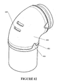
- FIG. 12 shows the outlet vent sleeve installed on the elbow
- FIG. 13 shows the outlet vent sleeve in isolation
- FIG. 14 shows the elbow in isolation
- FIG. 15 shows the one piece elbow outlet vent interior
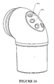
- FIG. 16 shows the one piece elbow outlet vent exterior
- FIG. 17 shows a cross section of the mouthpiece with a dispersing filter
- FIG. 18 shows a perspective view of the mask with cushion
- FIG. 19 is a cuttaway view of the mask showing the cushion
- FIG. 20 is a cuttaway view of the periphery of the outer membrane
- FIG. 21 is a cuttaway view of the periphery of the mask body portion
- FIG. 22 shows a make with the forehead rest on a user
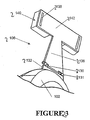
- FIG. 23 shows the forehead rest in isolation.
- the present invention provides improvements in the delivery of CPAP therapy.
- a patient interface is described which is quieter for the user to wear and reduces the side leakage as compared with the prior art.
- the patient interface as described in the preferred embodiment of the present invention can be used in respiratory care generally or with a ventilator but will now be described below with reference to use in a humidified CPAP system.
- the present invention can be applied to any form of patient interface including, but not limited to, nasal masks, oral masks and mouthpieces.
- CPAP Continuous Positive Airway Pressure
- a patient 1 is receiving humidified and pressurised gases through a patient interface 2 connected to a humidified gases transportation pathway or inspiratory conduit 3 .
- delivery systems could also be VPAP (Variable Positive Airway Pressure) and BiPAP (Bi-level Positive Airway Pressure) or numerous other forms of respiratory therapy.
- Inspiratory conduit 3 is connected to the outlet 4 of a humidification chamber 5 which contains a volume of water 6 .
- Inspiratory conduit 3 may contain heating means or heater wires (not shown) which heat the walls of the conduit to reduce condensation of humidified gases within the conduit.
- Humidification chamber 6 is preferably formed from a plastics material and may have a highly heat conductive base (for example an aluminium base) which is in direct contact with a heater plate 7 of humidifier 8 .
- Humidifier 8 is provided with control means or electronic controller 9 which may comprise a microprocessor based controller executing computer software commands stored in associated memory.
- Controller 9 receives input from sources such as user input means or dial 10 through which a user of the device may, for example, set a predetermined required value (preset value) of humidity or temperature of the gases supplied to patient 1 .
- the controller may also receive input from other sources, for example temperature and/or flow velocity sensors 11 and 12 through connector 13 and heater plate temperature sensor 14 .
- controller 9 determines when (or to what level) to energise heater plate 7 to heat the water 6 within humidification chamber 5 .
- water vapour begins to fill the volume of the chamber above the water's surface and is passed out of the humidification chamber 5 outlet 4 with the flow of gases (for example air) provided from a gases supply means or blower 15 which enters the chamber through inlet 16 . Exhaled gases from the patient's mouth are passed directly to ambient surroundings in FIG. 1.
- gases for example air
- Blower 15 is provided with variable pressure regulating means or variable speed fan 21 which draws air or other gases through blower inlet 17 .
- the speed of variable speed fan 21 is controlled by electronic controller 18 (or alternatively the function of controller 18 could carried out by controller 9 ) in response to inputs from controller 9 and a user set predetermined required value (preset value) of pressure or fan speed via dial 19 .
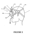
- the patient interface is shown in FIG. 2 as a nasal mask.
- the mask includes a hollow body 102 with an inlet 103 connected to the inspiratory conduit 3 .
- the mask 2 is positioned around the nose of the user 1 with the headgear 108 secured around the back of the head of the patient 1 .
- the restraining force from the headgear 108 on the hollow body 102 and the forehead rest 106 ensures enough compressive force on the mask cushion 104 , to provide an effective seal against the patient's face.
- the hollow body 102 is constructed of a relatively inflexible material for example, polycarbonate plastic. Such a material would provide the requisite rigidity as well as being transparent and a relatively good insulator.
- the expiratory gases can be expelled through a valve (not shown) in the mask, a further expiratory conduit (not shown), or any other such method as is known in the art.
- the mask cushion 1104 is provided around the periphery of the nasal mask 1102 to provide an effective seal onto the face of the user to prevent leakage.
- the mask cushion 1104 is shaped to approximately follow the contours of a patient's face.
- the mask cushion 104 will deform when pressure is applied by the headgear 1108 to adapt to the individual contours of any particular user.
- the mask cushion 1104 is composed of a inner foam cushion 1110 covered by an outer sealing sheath 1112 .
- the inner cushion 1110 is constructed of a resilient material for example polyurethane foam, to distribute the pressure evenly along the seal around the user's face.
- the inner cushion 1110 is located around the outer periphery 1114 of the open face 1116 of the hollow body 1102 .
- the outer sheath 1112 may be commonly attached at its base 1113 to the periphery 1114 and loosely covers over the top of the inner cushion 1110 .
- the bottom of the inner cushion 1110 fits into a generally triangular cavity 1154 in the hollow body 1102 .
- the cavity 1154 is formed from a flange 1156 running mid-way around the interior of the hollow body.
- the outer sheath 1112 fits in place over the cushion 1110 , holding it in place.
- the sheath 1112 is secured by a snap-fit to the periphery 1114 of the hollow body.
- the periphery 1114 is shown including an outer bead 1158 .
- the sheath 1112 includes a matching bead 1159 , whereby once stretched around the periphery, the two beads engage to hold the sheath in place.
- the nasal mask 2102 includes a hinged forehead rest 2106 (seen in FIGS. 22 and 23).
- the attachment of the forehead rest 2106 to the hollow body 2102 effectively allows the forehead rest 2106 to move freely in proximity to the user but with no lateral movement.
- pins 2130 are provided mounted on a base 2132 attached to the hollow body 2102 . These pins 2130 are co-axial within cylinders 21 - 31 mounted on a bridge member 2136 .
- harnessing slots 2138 are provided which allow straps from the headgear to be inserted to secure the mask to the headgear.
- one or more resilient cushions 2140 are provided underneath the top end 2142 of the bridge member 2136 , which rest on the forehead of the user.
- the cushion 2140 might be constructed of silicon or any foam materials as is known in the art for providing cushioning.
- the forehead rest 2106 described previously may include a weakened section 2130 at its base 2132 which allows the joining member 2136 to pivot from the hollow body 2102 .
- the bridge member extends up to the forehead of the user.
- the mask may include a vertical upwardly extending inlet.
- the member 2136 is hinged at its base 2132 to either side of the inlet passage. Again the member would then extend to the forehead.
- any well-known form of hinge can be used to provide the pivoting action.
- the patient interface 2 is shown in FIGS. 3 to 10 as a mouthpiece.
- the mouthpiece 50 includes a vestibular shield 49 being a generally flat and generally rectangularly-shaped member in front elevation having a curved profile that reflects the curvature of a user's jaw and in turn the curvature of the labial vestibule region.
- a gases passageway extends through the vestibular shield from an inlet 51 to an outlet 52 in much the same way as with the earlier embodiments.
- the inlet 51 is provided by a flattened oval-shaped connector 53 .
- the outlet 52 has an even more laterally extended flattened oval shape 54 .
- the mouthpiece 50 includes a tongue depressor 55 extending from the inner face of the vestibular shield 49 .
- the operation of the tongue depressor will be described further on with reference to FIG. 5
- the tongue depressor includes a vertical stiffening flange 56 centrally located on its upper surface and extending from the gases outlet 52 . In use gases flow easily around the stiffening flange 56 effectively bifurcating the gases outlet 52 .
- the tongue depressor 55 further includes a pair of vertically extending spacers 57 which in use may abut against the roof of the wearer's mouth and ensure that the tongue cannot completely block the air passageway.
- the sealing effect of the vestibular shield 49 against the lips of the user is enhanced by providing teeth abutments of significantly increased thickness than the raised area 20 of the earlier embodiments.
- an upper teeth abutment 58 and a lower teeth abutment 59 are provided, with the lower teeth abutment 59 protruding further from the inner face of the vestibular shield 49 than the upper teeth abutment 58 .
- This difference serves to match the typical over-bite of most users.
- the abutments 58 and 59 are not required to be wider than the gases outlet 52 .
- a notch 60 is provided centrally in the upper edge of the vestibular shield 49 to accommodate the upper frenal attachment.
- a slight bead 61 is provided around the edge of the vestibular shield 49 for user comfort, with the vestibular shield 49 otherwise being very thin for additional suppleness.
- the mouthpiece 50 is preferably formed by over-moulding a soft and supple material part 70 over a stiffer material part 67 .
- the passageway-forming insert preferably includes a pair of upper and lower vertical flanges 63 and 64 to fully engage within the supple material.
- the passageway-forming insert 67 includes the vertically extending stiffening flange 56 of the tongue depressor 55 , together with a curved planar portion 71 forming the backbone of the tongue depressor 55 .
- the vertically extending spacers 57 are of the soft and supple material and are part of the over-moulding 70 , a ⁇ are the upper and lower teeth abutments 58 and 59 .
- FIG. 7 use of the mouthpiece according to FIGS. 4 to 6 is depicted.
- the upper and lower lips 85 , 86 are further distended by the abutment action of the abutments 75 , 76 against the upper and lower teeth 87 , 88 respectively, thus forming a seal of greater pressure between the lips 85 , 86 and the upper and lower portions respectively of the vestibular shield 49 .
- a lower face 77 of the tongue depressor 55 impinges if necessary on the upper surface 72 of the tongue 85 and retains the tongue in the lower portion of the mouth. This ensures a clear gases outlet 52 from the gases passageway through the vestibular shield.
- the vertically extending spacers 57 if forced by pressure from the tongue, will engage against the roof of the user's mouth and maintain a clear air passageway. This stops the sleeping patient unconsciously blocking the oral passageway and reverting to nasal breathing.
- FIG. 8 of the present invention is illustrated including an extra-oral sealing flap 110 .
- the flap 110 in its natural bias is tapered, the wide open end of which is shaped to conform to the facial contours around the outside of the mouth of a user.
- the narrow end joins to a cylindrical section, which is designed to slide over the inlet port 114 of the mouthpiece 112 . While this is one method of attachment the flap 100 might also be constructed as an integral part of the mouthpiece 112 .
- the flap 110 needs to be constructed of flexible material, therefore materials such as silicone rubber can be employed to fashion the flap.
- the outer flap 110 is seen in FIG. 9, in a bent back position. It will be appreciated that when the mouthpiece 112 is being inserted into the mouth of a user, the outer flap 110 is intended to be in this bent back position to aid insertion. Prior to insertion, the outer flap is bent back by simply pressing on its outer periphery 116 , until it snaps into the bent back position, in which it will stay unaided.
- FIG. 10 we see the outer flap 110 in use with the mouthpiece 112 in the mouth 117 of a user 120 .
- the outer flap 110 may be adjusted into its operational position by pressing on its outer periphery 116 until it snaps back to press against the outside of the mouth 118 . Due to the relative position of the vestibular shield 122 and the outer flap 110 , the outer flap 110 is unable to fully reach its natural bias and thereby inflicts a compressive force on the outside of the mouth 118 .
- the outer flap 300 is shown in perspective. Included are ventilation apertures 302 , 303 either side of the gases port 304 , which are surrounded by a ridge 306 acting as a moisture barrier.
- the apertures 302 , 303 are provided such that any excess moisture leaking from the mouth will migrate to the apertures where they may evaporate. Small vents in the conduit may be used to direct small amounts of pressurised gas at the apertures to aid evaporation.
- the ridge 306 is included to ensure that no moisture migrates further into the sealing region 308 , as this would be detrimental to the sealing properties of the flap.
- FIG. 3 Attention is now directed to FIG. 3. It has been found that an additional factor in the effectiveness of any patient interface 2 , is the manner in which the interface is connected to the breathing circuit 41 .
- the weight of the breathing circuit 41 and any attempted movement of one other of the breathing circuit 41 and the interface 2 relative to the other, is one of the largest influences tending to dislodge the interface 2 . It must be noted that the interface 2 must remain in position and maintain a seal during all sleep, when the user has no muscle tone.
- connection 40 as provided in the present invention between the breathing circuit 41 and the interface 2 decouples the interface 2 from the breathing circuit 41 .
- the connection 40 is effective in reducing the forces placed on the interface 2 by the breathing circuit 41 when the user moves around during sleep.
- the breathing circuit 41 is laid across the chest 43 of the user, and may be secured to the user's bed clothes or sleeping garments.
- the breathing circuit 41 is preferably laid on the chest of the user to take the weight of the breathing circuit 41 off of the interface 2 .
- an L-shaped elbow 45 is incorporated in the connection 40 .
- the elbow 45 may be incorporated in the interface 2 .
- the elbow 45 is formed at a right angle and provides a positive pressure on the interface 2 .
- the elbow 45 may include a swivel joint and may be disconnected from gaseous outlet 42 .
- the connection 40 further includes an extremely flexible connecting tube 46 provided between the elbow 45 and the breathing circuit 41 .
- the connecting tube 46 is preferably connected to the breathing circuit 41 by a swivel joint 48 for reasons described herein.
- the breathing circuit 41 while flexible, will necessarily be stiff enough to maintain its integrity over comparatively long tuns, while the connecting tube 46 , being only a short length, for example 10 centimetres, merely has to span between the user's mouth and chest, and can thereby be made in a manner that would not be suitable for long runs. Furthermore, as a result of the short length of the connecting tube 46 , the connecting tube 46 does not need to incorporate significant insulation or heating capability.
- the connecting tube 46 may be formed from a thin plastic membrane supported over a helical or double helical or corrugated supporting ribs. In such a case, the support makes the connection tube 46 laterally flexible and resistant to torsion.
- the elbow swivel joint 45 allows for movement of the connection tube 46 relative to the interface 2 .
- the swivel joint 48 allows for movement of the connection tube 46 relative to the breathing circuit 41 . It is to be understood that one or both of the swivel joints 45 , 48 could be eliminated, but the preferred embodiment includes swivel joint 48 .
- FIGS. 12 to 17 In order to reduce the noise caused by expiratory gases being expelled from the patient interface 2 , the present invention is illustrated in FIGS. 12 to 17 with the elbow connector (previously designated as 45 ) including an outlet vent. It would be appreciated by one skilled in the art that the elbow connector as described herein will be equally applicable to all proceeding embodiments and all other forms of patient interface for delivering CPAP therapy.
- the elbow connector is illustrated including a flexible sleeve 400 which fits overtop of the elbow connector.
- the sleeve 400 is preferably constructed of silicon) but it will be appreciated by one skilled in the art that a number of other flexible materials will be equally applicable.
- the sleeve 400 includes locating indents 402 which once installed on the elbow connector match up with and lock into locating notches 404 on the elbow connector. The location is necessary so that the outlet aperture 406 in the elbow connector always matches up with the outlet vents 408 in the outlet sleeve 400 . This then prevents the undesirable situation where the sleeve could slip and the outlet vents 408 not match up with the outlet aperture 406 with resulting consequences to the patient.
- the present invention is shown with a one-piece elbow.
- the elbow is preferably constructed of either “Hytrel” plastic or polycarbonate.
- the elbow connector is manufactured to have a thin portion 410 surrounding the outlet vents 412 in comparison to the remainder of the elbow connector which is considerably thicker.
- the properties of the material chosen for the elbow connector are such that its flexibility is dependent on its thickness. Therefore in the thin section 410 the elbow connector is relatively flexible and in the remainder is relatively rigid.
- the outlet vents 412 which are also rounded on their periphery are formed in a flexible portion, and therefore achieve the desirable low noise properties when expiratory gases are vented therethrough.
- FIG. 17 includes a mouthpiece with a flow diffuser 500 .
- the mouthpiece sits with a vestibular shield 502 between the gums 504 and the lips 506 of a user.
- An outer flap 508 provides compressor force on the lips 506 to keep the mouthpiece in place in the user's mouth.
- the mouthpiece includes a tough depressor 510 extending into the user's oral cavity.
- the delivered gases would flow through passageway 512 in the mouthpiece, causing a relatively concentrated flow of gases to flow through the oral cavity and down the airway.
- the flow diffuser 500 fitted overtop of the passageway 512 the flow is defused over the much larger area of the diffuser 500 , and therefore both the speed and side effects are reduced.
- the space between the passageway 512 and the diffuser 500 could be filled with a Humidity Moisture Exchange (HME) material. This would allow moisture through on the inspiratory flow put prevent it passing out an expiration. This would further prevent against the patient's passageways drying out. Further, if the HME material was in the form of foam, then it might also act as the diffuser 500 . It will also be appreciated that the HME material could be used in the space 516 all the way out to the elbow connector (not shown) to maximise its effect.
- HME Humidity Moisture Exchange
- the present invention effectively minimises the noise generated by the outward flow of expiratory gases from the mask.
- the present invention requires little or no maintenance.
- the present invention also provides a flow diffuser for use with the mouthpiece, which reduces any side effects of orally delivered CPAP therapy and improves user comfort.
Abstract
A CPAP system for supplying humidified gases to a user. Various interfaces are described for delivering the gases. A mask cushion including a deformable cushion and a thin sheath is described. A forehead rest with a horizontal pivot is attached to the mask. An outlet vent to reduce the noise from exhausted carbon dioxide is described. A mouthpiece is also described with an outlet diffuser including Heat Moisture Exchanger Material.
Description
- This invention relates to patient interfaces particularly though not solely for use in delivering CPAP therapy to patients suffering from obstructive sleep apnoea (OSA).
- In the art of respiration devices, there are well known variety of respiratory masks which cover the nose and/or mouth of a human user in order to provide a continuous seal around the nasal and/or oral areas of the face such that gas may be provided at positive pressure within the mask for consumption by the user. The uses for such masks range from high altitude breathing (i.e., aviation applications) to mining and fire fighting applications, to various medical diagnostic and therapeutic applications.
- One requisite of such respiratory masks has been that they provide an effective seal against the user's face to prevent leakage of the gas being supplied. Commonly, in prior mask configurations, a good mask-to-face seal has been attained in many instances only with considerable discomfort for the user. This problem is most crucial in those applications, especially medical applications, which require the user to wear such a mask continuously for hours or perhaps even days. In such situations, the user will not tolerate the mask for long durations and optimum therapeutic or diagnostic objectives thus will not be achieved, or will be achieved with great difficulty and considerable user discomfort.
- U.S. Pat. No. 5,243,971 and U.S. Pat. No. 6,112,746 are examples of prior art attempts to improve the mask system U.S. Pat. No. 5,570,689 and PCT publication No. WO 00/78384 are examples of attempts to improve the forehead rest.
- Where such masks are used in respiratory therapy, in particular treatment of obstructive sleep apnea (OSA) using continuance positive airway pressure (CPAP) therapy, there is generally provided in the art a vent for washout of the bias flow or expired gases to the atmosphere. Such a vent may be provided for example, as part of the mask, or in the case of some respirators where a further conduit carries the expiratory gases, at the respirator. A further requisite of such masks is the washout of gas from the mask to ensure that carbon dioxide build up does not occur over the range of flow rates. In the typical flow rates in CPAP treatment, usually between 4 cm H 2O to 20 cm H2O, prior art attempts at such vents have resulted in excessive noise causing irritation to the user and any bed partners.
- Various approaches have been developed in the prior art to attempt to reduce the noise when CPAP therapy is provided. For example, in PCT Patent Application No. WO98/34665 it has been proposed that the vent include a resilient plug with rounded edge apertures to reproduce noise. However, this is not entirely effective in eliminating the extra noise created by a vent at the mask.
- In common with all attempts to improve the fit, sealing and user comfort is the need to avoid a concentrated flow of air at any portion of the respiratory tracts. In particular with oral masks or mouthpieces it is a disadvantage of prior art devices that the oral cavity may become overly dehydrated by use of the device, causing irritation and possible later complications.
- It is an object of the present invention to attempt to provide a patient interface which goes some way to overcoming the abovementioned disadvantages in the prior art or which will at least provide the industry with a useful choice.
- Accordingly in one aspect the invention may broadly be said to consist in a device for delivering a supply of gases to a user comprising:
- a patient interface, in use in fluid communication with said supply of gases, engaging with said user and thereby supplying said gases to said user.
- outlet means associated with said patient interface including a plurality of outlet vents formed in a flexible portion of said outlet means, said outlet means in use passing a substantial portion of the expired gases of said user.
- Preferably said patient interface is a mouthpiece.
- Alternatively said patient interface is a nasal mask.
- Preferably said mouthpiece comprises:
- a vestibular shield having an inner surface and an outer surface, said vestibular shield having a predetermined height which will overlap said user's teeth and gums when positioned in the mouth vestibule of said user;
- gases passageway means extending from said outer surface of said vestibular shield to said inner surface of said vestibular shield for allowing the passage of said gases through said mouthpiece; and
- extra-oral sealing means associated with said gases passageway which may be adjusted into one of two configurations, a first condition when said mouthpiece is inserted into said user's mouth being substantially unengaged with said user's face, and a second condition when correctly positioned in said user's mouth being substantially engaged with said user's face and under compression thereupon.
- Preferably said nasal mask comprises restraining means attached to or around the head of said user, a hard body portion having an inlet receiving said supply of gases and an open section, sealing means attached to said body portion substantially contoured to the facial contours of said user and a receiving means attached to said hard body which in use engages with said restraining means.
- Preferably said flexible portion of said outlet means comprises a sleeve having a plurality of outlet vents, said sleeve attaching over said outlet means, said sleeve composed of a substantially flexible material, said outlet means having a outlet aperture and in use said sleeve located on said outlet means such that said outlet aperture matches up with said plurality of outlet vents thereby in use passing a substantial portion of the expired gases of said user.
- Alternatively, said outlet means is either integral or in fluid communication with said patient interface, said outlet means being composed substantially of a single material, and said flexible portion comprising a portion of said outlet means in which the thickness of said material is substantially less than, and therefore substantially more flexible than, the remainder of said outlet means.
- To those skilled in the art to which the invention relates, many changes in construction and widely differing embodiments and applications of the invention will suggest themselves without departing from the scope of the invention as defined in the appended claims. The disclosures and the descriptions herein are purely illustrative and are not intended to be in any sense limiting.
- The invention consists in the foregoing and also envisages constructions of which the following gives examples.
- One preferred form of the present invention will now be described with reference to the accompanying drawings in which;
- FIG. 1 is a block diagram of a humidified continuous positive airway pressure (system) as might be used in conjunction with the present invention,
- FIG. 2 is an illustration of the nasal mask in use according to the preferred embodiment of the present invention,
- FIG. 3 is a side elevational view of the mouthpiece as being used by a patient,
- FIG. 4 is a perspective view from above of the mouthpiece,
- FIG. 5 is a perspective view from one side and from an inward direction of the mouthpiece of FIG. 4,
- FIG. 6 is a cross-section of the mouthpiece of FIG. 4,
- FIG. 7 is a cross-sectional view of the mouthpiece of FIG. 4 and a user with the mouthpiece in place to demonstrate the location and positioning thereof in relation to the main features of the user's anatomy,
- FIG. 8 is a perspective view of the mouthpiece with the outer flap in place,
- FIG. 9 is a perspective view of the outer flap bent back,
- FIG. 10 is a cutaway view of the mouthpiece with the outer flap in use,
- FIG. 11 is a perspective view of the outer flap including the ventilation apertures and moisture barrier,
- FIG. 12 shows the outlet vent sleeve installed on the elbow,
- FIG. 13 shows the outlet vent sleeve in isolation,
- FIG. 14 shows the elbow in isolation,
- FIG. 15 shows the one piece elbow outlet vent interior,
- FIG. 16 shows the one piece elbow outlet vent exterior,
- FIG. 17 shows a cross section of the mouthpiece with a dispersing filter,
- FIG. 18 shows a perspective view of the mask with cushion,
- FIG. 19 is a cuttaway view of the mask showing the cushion,
- FIG. 20 is a cuttaway view of the periphery of the outer membrane,
- FIG. 21 is a cuttaway view of the periphery of the mask body portion,
- FIG. 22 shows a make with the forehead rest on a user, and
- FIG. 23 shows the forehead rest in isolation.
- The present invention provides improvements in the delivery of CPAP therapy. In particular a patient interface is described which is quieter for the user to wear and reduces the side leakage as compared with the prior art. It will be appreciated that the patient interface as described in the preferred embodiment of the present invention can be used in respiratory care generally or with a ventilator but will now be described below with reference to use in a humidified CPAP system. It will also be appreciated that the present invention can be applied to any form of patient interface including, but not limited to, nasal masks, oral masks and mouthpieces.
- With reference to FIG. 1 a humidified Continuous Positive Airway Pressure (CPAP) system is shown in which a
patient 1 is receiving humidified and pressurised gases through apatient interface 2 connected to a humidified gases transportation pathway orinspiratory conduit 3. It should be understood that delivery systems could also be VPAP (Variable Positive Airway Pressure) and BiPAP (Bi-level Positive Airway Pressure) or numerous other forms of respiratory therapy.Inspiratory conduit 3 is connected to the outlet 4 of ahumidification chamber 5 which contains a volume ofwater 6.Inspiratory conduit 3 may contain heating means or heater wires (not shown) which heat the walls of the conduit to reduce condensation of humidified gases within the conduit.Humidification chamber 6 is preferably formed from a plastics material and may have a highly heat conductive base (for example an aluminium base) which is in direct contact with aheater plate 7 ofhumidifier 8.Humidifier 8 is provided with control means orelectronic controller 9 which may comprise a microprocessor based controller executing computer software commands stored in associated memory. -
Controller 9 receives input from sources such as user input means or dial 10 through which a user of the device may, for example, set a predetermined required value (preset value) of humidity or temperature of the gases supplied topatient 1. The controller may also receive input from other sources, for example temperature and/or flowvelocity sensors connector 13 and heaterplate temperature sensor 14. In response to the user set humidity or temperature value input viadial 10 and the other inputs,controller 9 determines when (or to what level) to energiseheater plate 7 to heat thewater 6 withinhumidification chamber 5. As the volume ofwater 6 withinhumidification chamber 5 is heated, water vapour begins to fill the volume of the chamber above the water's surface and is passed out of thehumidification chamber 5 outlet 4 with the flow of gases (for example air) provided from a gases supply means orblower 15 which enters the chamber throughinlet 16. Exhaled gases from the patient's mouth are passed directly to ambient surroundings in FIG. 1. -
Blower 15 is provided with variable pressure regulating means orvariable speed fan 21 which draws air or other gases throughblower inlet 17. The speed ofvariable speed fan 21 is controlled by electronic controller 18 (or alternatively the function ofcontroller 18 could carried out by controller 9) in response to inputs fromcontroller 9 and a user set predetermined required value (preset value) of pressure or fan speed viadial 19. - Nasal Mask
- According to a first embodiment of the present invention the patient interface is shown in FIG. 2 as a nasal mask. The mask includes a
hollow body 102 with aninlet 103 connected to theinspiratory conduit 3. Themask 2 is positioned around the nose of theuser 1 with theheadgear 108 secured around the back of the head of thepatient 1. The restraining force from theheadgear 108 on thehollow body 102 and theforehead rest 106 ensures enough compressive force on themask cushion 104, to provide an effective seal against the patient's face. - The
hollow body 102 is constructed of a relatively inflexible material for example, polycarbonate plastic. Such a material would provide the requisite rigidity as well as being transparent and a relatively good insulator. The expiratory gases can be expelled through a valve (not shown) in the mask, a further expiratory conduit (not shown), or any other such method as is known in the art. - Mask Cushion
- Referring now to FIGS. 18 and 19 in particular, the mask cushion 1104 is provided around the periphery of the nasal mask 1102 to provide an effective seal onto the face of the user to prevent leakage. The mask cushion 1104 is shaped to approximately follow the contours of a patient's face. The
mask cushion 104 will deform when pressure is applied by the headgear 1108 to adapt to the individual contours of any particular user. In particular, there is an indented section 1150 intended to fit over the bridge of the user's nose as well as a less indented section 1152 to seal around the section beneath the nose and above the upper lip. - In FIG. 19 we see that the mask cushion 1104 is composed of a
inner foam cushion 1110 covered by an outer sealing sheath 1112. Theinner cushion 1110 is constructed of a resilient material for example polyurethane foam, to distribute the pressure evenly along the seal around the user's face. Theinner cushion 1110 is located around the outer periphery 1114 of the open face 1116 of the hollow body 1102. Similarly the outer sheath 1112 may be commonly attached at its base 1113 to the periphery 1114 and loosely covers over the top of theinner cushion 1110. - In the preferred embodiment shown in FIGS. 19-21 the bottom of the
inner cushion 1110 fits into a generally triangular cavity 1154 in the hollow body 1102. The cavity 1154 is formed from a flange 1156 running mid-way around the interior of the hollow body. - The outer sheath 1112 fits in place over the
cushion 1110, holding it in place. The sheath 1112 is secured by a snap-fit to the periphery 1114 of the hollow body. In FIGS. 20-21 the periphery 1114 is shown including an outer bead 1158. The sheath 1112 includes a matching bead 1159, whereby once stretched around the periphery, the two beads engage to hold the sheath in place. - Forehead Rest
- In the preferred embodiment of the present invention the
nasal mask 2102 includes a hinged forehead rest 2106 (seen in FIGS. 22 and 23). The attachment of the forehead rest 2106 to thehollow body 2102 effectively allows the forehead rest 2106 to move freely in proximity to the user but with no lateral movement. - In one form shown in FIG. 23,
pins 2130 are provided mounted on abase 2132 attached to thehollow body 2102. Thesepins 2130 are co-axial within cylinders 21-31 mounted on a bridge member 2136. - At the top end 2142 (around the user's forehead) of the bridge member 2136
harnessing slots 2138 are provided which allow straps from the headgear to be inserted to secure the mask to the headgear. For the user's comfort one or more resilient cushions 2140 are provided underneath thetop end 2142 of the bridge member 2136, which rest on the forehead of the user. The cushion 2140 might be constructed of silicon or any foam materials as is known in the art for providing cushioning. - For example the forehead rest 2106 described previously may include a weakened
section 2130 at its base 2132 which allows the joining member 2136 to pivot from thehollow body 2102. The bridge member extends up to the forehead of the user. In a further alternative the mask may include a vertical upwardly extending inlet. In this case the member 2136 is hinged at its base 2132 to either side of the inlet passage. Again the member would then extend to the forehead. - Alternatively any well-known form of hinge can be used to provide the pivoting action.
- Mouthpiece
- Now with reference to a further inlet embodiment of the present invention the
patient interface 2 is shown in FIGS. 3 to 10 as a mouthpiece. In this embodiment, themouthpiece 50 includes avestibular shield 49 being a generally flat and generally rectangularly-shaped member in front elevation having a curved profile that reflects the curvature of a user's jaw and in turn the curvature of the labial vestibule region. A gases passageway extends through the vestibular shield from aninlet 51 to anoutlet 52 in much the same way as with the earlier embodiments. In the preferred embodiment theinlet 51 is provided by a flattened oval-shapedconnector 53. Theoutlet 52 has an even more laterally extended flattenedoval shape 54. The major differences between themouthpiece 50 and the embodiments described above are provided on the inner face of the vestibular shield. Most prominently, themouthpiece 50 includes atongue depressor 55 extending from the inner face of thevestibular shield 49. The operation of the tongue depressor will be described further on with reference to FIG. 5 The tongue depressor includes avertical stiffening flange 56 centrally located on its upper surface and extending from thegases outlet 52. In use gases flow easily around the stiffeningflange 56 effectively bifurcating thegases outlet 52. Thetongue depressor 55 further includes a pair of vertically extendingspacers 57 which in use may abut against the roof of the wearer's mouth and ensure that the tongue cannot completely block the air passageway. In themouthpiece 50 the sealing effect of thevestibular shield 49 against the lips of the user is enhanced by providing teeth abutments of significantly increased thickness than the raisedarea 20 of the earlier embodiments. In particular, anupper teeth abutment 58 and alower teeth abutment 59 are provided, with thelower teeth abutment 59 protruding further from the inner face of thevestibular shield 49 than theupper teeth abutment 58. This difference serves to match the typical over-bite of most users. Theabutments gases outlet 52. - A
notch 60 is provided centrally in the upper edge of thevestibular shield 49 to accommodate the upper frenal attachment. Aslight bead 61 is provided around the edge of thevestibular shield 49 for user comfort, with thevestibular shield 49 otherwise being very thin for additional suppleness. - Referring particularly to FIG. 6, in its preferred form the
mouthpiece 50 is preferably formed by over-moulding a soft andsupple material part 70 over astiffer material part 67. These can generally be termed the shield part and the passageway-forming insert. The passageway-forming insert preferably includes a pair of upper and lowervertical flanges insert 67 includes the vertically extendingstiffening flange 56 of thetongue depressor 55, together with a curvedplanar portion 71 forming the backbone of thetongue depressor 55. The vertically extendingspacers 57 are of the soft and supple material and are part of the over-moulding 70, a§are the upper andlower teeth abutments - Referring now to FIG. 7, use of the mouthpiece according to FIGS. 4 to 6 is depicted. With the
present mouthpiece 50, the upper andlower lips abutments lower teeth 87, 88 respectively, thus forming a seal of greater pressure between thelips vestibular shield 49. Alower face 77 of thetongue depressor 55 impinges if necessary on theupper surface 72 of thetongue 85 and retains the tongue in the lower portion of the mouth. This ensures aclear gases outlet 52 from the gases passageway through the vestibular shield. The vertically extendingspacers 57, if forced by pressure from the tongue, will engage against the roof of the user's mouth and maintain a clear air passageway. This stops the sleeping patient unconsciously blocking the oral passageway and reverting to nasal breathing. - Referring now to FIG. 8 of the present invention is illustrated including an
extra-oral sealing flap 110. Theflap 110 in its natural bias is tapered, the wide open end of which is shaped to conform to the facial contours around the outside of the mouth of a user. The narrow end joins to a cylindrical section, which is designed to slide over theinlet port 114 of themouthpiece 112. While this is one method of attachment the flap 100 might also be constructed as an integral part of themouthpiece 112. Theflap 110 needs to be constructed of flexible material, therefore materials such as silicone rubber can be employed to fashion the flap. - The
outer flap 110 is seen in FIG. 9, in a bent back position. It will be appreciated that when themouthpiece 112 is being inserted into the mouth of a user, theouter flap 110 is intended to be in this bent back position to aid insertion. Prior to insertion, the outer flap is bent back by simply pressing on itsouter periphery 116, until it snaps into the bent back position, in which it will stay unaided. - In FIG. 10 we see the
outer flap 110 in use with themouthpiece 112 in themouth 117 of auser 120. Once correctly positioned in themouth 116, theouter flap 110 may be adjusted into its operational position by pressing on itsouter periphery 116 until it snaps back to press against the outside of themouth 118. Due to the relative position of thevestibular shield 122 and theouter flap 110, theouter flap 110 is unable to fully reach its natural bias and thereby inflicts a compressive force on the outside of themouth 118. - It will be appreciated that as well as providing a substantially airtight seal the addition of the outer flap provides enough compressive force on the mouth to keep the mouthpiece and conduit in place without the need for straps. This allows the administering of CPAP therapy to be considerably less obtrusive than traditional methods.
- In a further additional improvement shown in FIG. 11, the
outer flap 300 is shown in perspective. Included areventilation apertures gases port 304, which are surrounded by aridge 306 acting as a moisture barrier. Theapertures ridge 306 is included to ensure that no moisture migrates further into the sealing region 308, as this would be detrimental to the sealing properties of the flap. - Interface Connection
- Attention is now directed to FIG. 3. It has been found that an additional factor in the effectiveness of any
patient interface 2, is the manner in which the interface is connected to thebreathing circuit 41. The weight of thebreathing circuit 41, and any attempted movement of one other of thebreathing circuit 41 and theinterface 2 relative to the other, is one of the largest influences tending to dislodge theinterface 2. It must be noted that theinterface 2 must remain in position and maintain a seal during all sleep, when the user has no muscle tone. - The
connection 40 as provided in the present invention between thebreathing circuit 41 and theinterface 2 decouples theinterface 2 from thebreathing circuit 41. As a result, theconnection 40 is effective in reducing the forces placed on theinterface 2 by thebreathing circuit 41 when the user moves around during sleep. In the preferred sleeping position, thebreathing circuit 41 is laid across thechest 43 of the user, and may be secured to the user's bed clothes or sleeping garments. Thebreathing circuit 41 is preferably laid on the chest of the user to take the weight of thebreathing circuit 41 off of theinterface 2. - To connect between the
gases outlet 14 which is vertical when the user is laying on his or her back and thebreathing circuit 41 which is generally horizontal, an L-shapedelbow 45 is incorporated in theconnection 40. Theelbow 45 may be incorporated in theinterface 2. Theelbow 45 is formed at a right angle and provides a positive pressure on theinterface 2. Theelbow 45 may include a swivel joint and may be disconnected fromgaseous outlet 42. Theconnection 40 further includes an extremely flexible connectingtube 46 provided between theelbow 45 and thebreathing circuit 41. The connectingtube 46 is preferably connected to thebreathing circuit 41 by a swivel joint 48 for reasons described herein. Thebreathing circuit 41, while flexible, will necessarily be stiff enough to maintain its integrity over comparatively long tuns, while the connectingtube 46, being only a short length, for example 10 centimetres, merely has to span between the user's mouth and chest, and can thereby be made in a manner that would not be suitable for long runs. Furthermore, as a result of the short length of the connectingtube 46, the connectingtube 46 does not need to incorporate significant insulation or heating capability. The connectingtube 46 may be formed from a thin plastic membrane supported over a helical or double helical or corrugated supporting ribs. In such a case, the support makes theconnection tube 46 laterally flexible and resistant to torsion. The elbow swivel joint 45 allows for movement of theconnection tube 46 relative to theinterface 2. The swivel joint 48 allows for movement of theconnection tube 46 relative to thebreathing circuit 41. It is to be understood that one or both of the swivel joints 45, 48 could be eliminated, but the preferred embodiment includes swivel joint 48. - Outlet Vent
- The present invention will now be described with reference to the various different embodiments previously described. In order to reduce the noise caused by expiratory gases being expelled from the
patient interface 2, the present invention is illustrated in FIGS. 12 to 17 with the elbow connector (previously designated as 45) including an outlet vent. It would be appreciated by one skilled in the art that the elbow connector as described herein will be equally applicable to all proceeding embodiments and all other forms of patient interface for delivering CPAP therapy. - Referring particularly now to FIGS. 12 to 14, the elbow connector is illustrated including a
flexible sleeve 400 which fits overtop of the elbow connector. Thesleeve 400 is preferably constructed of silicon) but it will be appreciated by one skilled in the art that a number of other flexible materials will be equally applicable. Thesleeve 400 includes locatingindents 402 which once installed on the elbow connector match up with and lock into locatingnotches 404 on the elbow connector. The location is necessary so that theoutlet aperture 406 in the elbow connector always matches up with the outlet vents 408 in theoutlet sleeve 400. This then prevents the undesirable situation where the sleeve could slip and the outlet vents 408 not match up with theoutlet aperture 406 with resulting consequences to the patient. - Referring now to FIGS. 15 and 16, the present invention is shown with a one-piece elbow. In this case the elbow is preferably constructed of either “Hytrel” plastic or polycarbonate. In this fashion the elbow connector is manufactured to have a
thin portion 410 surrounding the outlet vents 412 in comparison to the remainder of the elbow connector which is considerably thicker. The properties of the material chosen for the elbow connector are such that its flexibility is dependent on its thickness. Therefore in thethin section 410 the elbow connector is relatively flexible and in the remainder is relatively rigid. Accordingly the outlet vents 412, which are also rounded on their periphery are formed in a flexible portion, and therefore achieve the desirable low noise properties when expiratory gases are vented therethrough. - Flow Diffuser
- Referring now particularly to the use of mouthpieces, a further improvement is shown in FIG. 17. It is documented that when CPAP therapy is delivered to patients they often complain of drying of the airways and resulting irritation and discomfort. In particular when a concentrated airflow of under humidified gases flows past the oral or nasal cavities, or the airway of the user then drying and irritation may occur. Accordingly the present invention as illustrated in FIG. 17 includes a mouthpiece with a
flow diffuser 500. - As described in the preceding embodiments, the mouthpiece sits with a
vestibular shield 502 between thegums 504 and thelips 506 of a user. Anouter flap 508 provides compressor force on thelips 506 to keep the mouthpiece in place in the user's mouth. Again the mouthpiece includes a tough depressor 510 extending into the user's oral cavity. - In the preceding embodiments the delivered gases would flow through
passageway 512 in the mouthpiece, causing a relatively concentrated flow of gases to flow through the oral cavity and down the airway. With theflow diffuser 500 fitted overtop of thepassageway 512 the flow is defused over the much larger area of thediffuser 500, and therefore both the speed and side effects are reduced. - Alternatively the space between the
passageway 512 and thediffuser 500 could be filled with a Humidity Moisture Exchange (HME) material. This would allow moisture through on the inspiratory flow put prevent it passing out an expiration. This would further prevent against the patient's passageways drying out. Further, if the HME material was in the form of foam, then it might also act as thediffuser 500. It will also be appreciated that the HME material could be used in thespace 516 all the way out to the elbow connector (not shown) to maximise its effect. - It will be appreciated that by providing such a system the present invention effectively minimises the noise generated by the outward flow of expiratory gases from the mask. The present invention requires little or no maintenance. The present invention also provides a flow diffuser for use with the mouthpiece, which reduces any side effects of orally delivered CPAP therapy and improves user comfort.
Claims (5)
1. A mouthpiece for delivering a supply of gases to a user from a breathing assistance apparatus comprising:
engagement means adapted to in use juxtapose said mouthpiece in or about the oral cavity of a user and substantially seal thereabouts,
a conduit adapted to fluidically communicate a breathing assistance apparatus with the oral cavity of a user, and
diffusing means adapted to be in fluid communication with said conduit and located substantially within, and delivering said supply of gases in a substantially diffused manner to, the oral cavity of a user.
2. A mouthpiece for delivering a supply of gases to a user as claimed in claim 1 wherein said conduit includes an inlet, in use fluid communication with said supply of gases, and an outlet in fluid communication with said inlet, said diffusing means including a diffusing material engaged over said outlet in use through which said gases pass and are thereby discharged in a diffused manner.
3. A mouthpiece for delivering a supply of gases to a user as claimed in claim 2 wherein said diffusing material comprises a portion of porous material in use through which said gases pass.
4. A mouthpiece for delivering a supply of gases to a user as claimed in claim 3 wherein said porous material is material chosen from those known to have heat and moisture exchanging properties.
5. A mouthpiece for delivering a supply of gases to a user as claimed in claim 4 wherein said material substantially allows moisture to pass inwardly from said conduit to, but prevents egress outwardly from, the oral cavity of a user.
Priority Applications (6)
| Application Number | Priority Date | Filing Date | Title |
|---|---|---|---|
| US10/456,661 US20030196659A1 (en) | 2000-06-14 | 2003-06-06 | Breathing assistance apparatus |
| US11/368,004 US8100126B2 (en) | 2000-06-14 | 2006-03-03 | Breathing assistance apparatus |
| US11/928,779 US8602029B2 (en) | 2000-06-14 | 2007-10-30 | Breathing assistance apparatus |
| US12/410,863 US8613279B2 (en) | 2000-06-14 | 2009-03-25 | Breathing assistance apparatus |
| US14/136,930 US9707368B2 (en) | 2000-06-14 | 2013-12-20 | Breathing assistance apparatus |
| US15/651,957 US20180001047A1 (en) | 2000-06-14 | 2017-07-17 | Breathing assistance apparatus |
Applications Claiming Priority (10)
| Application Number | Priority Date | Filing Date | Title |
|---|---|---|---|
| NZ50515600 | 2000-06-14 | ||
| NZ505154 | 2000-06-14 | ||
| NZ50515400 | 2000-06-14 | ||
| NZ505156 | 2000-06-14 | ||
| NZ509039 | 2000-12-20 | ||
| NZ50903900 | 2000-12-20 | ||
| NZ51052001 | 2001-03-12 | ||
| NZ510520 | 2001-03-12 | ||
| US10/297,951 US20030154978A1 (en) | 2000-06-14 | 2001-06-14 | Breathing assistance apparatus |
| US10/456,661 US20030196659A1 (en) | 2000-06-14 | 2003-06-06 | Breathing assistance apparatus |
Related Parent Applications (4)
| Application Number | Title | Priority Date | Filing Date |
|---|---|---|---|
| US10297951 Division | 2001-06-14 | ||
| PCT/NZ2001/000110 Division WO2001095965A1 (en) | 2000-06-14 | 2001-06-14 | Breathing assistance apparatus |
| US10/297,951 Division US20030154978A1 (en) | 2000-06-14 | 2001-06-14 | Breathing assistance apparatus |
| US11/368,004 Division US8100126B2 (en) | 2000-06-14 | 2006-03-03 | Breathing assistance apparatus |
Related Child Applications (2)
| Application Number | Title | Priority Date | Filing Date |
|---|---|---|---|
| US11/368,004 Continuation-In-Part US8100126B2 (en) | 2000-06-14 | 2006-03-03 | Breathing assistance apparatus |
| US11/928,779 Continuation US8602029B2 (en) | 2000-06-14 | 2007-10-30 | Breathing assistance apparatus |
Publications (1)
| Publication Number | Publication Date |
|---|---|
| US20030196659A1 true US20030196659A1 (en) | 2003-10-23 |
Family
ID=27484393
Family Applications (7)
| Application Number | Title | Priority Date | Filing Date |
|---|---|---|---|
| US10/297,951 Abandoned US20030154978A1 (en) | 2000-06-14 | 2001-06-14 | Breathing assistance apparatus |
| US10/395,446 Expired - Lifetime US6951218B2 (en) | 2000-06-14 | 2003-03-24 | Breathing assistance apparatus |
| US10/456,661 Abandoned US20030196659A1 (en) | 2000-06-14 | 2003-06-06 | Breathing assistance apparatus |
| US11/928,779 Active 2025-07-04 US8602029B2 (en) | 2000-06-14 | 2007-10-30 | Breathing assistance apparatus |
| US12/410,863 Expired - Lifetime US8613279B2 (en) | 2000-06-14 | 2009-03-25 | Breathing assistance apparatus |
| US14/136,930 Expired - Lifetime US9707368B2 (en) | 2000-06-14 | 2013-12-20 | Breathing assistance apparatus |
| US15/651,957 Abandoned US20180001047A1 (en) | 2000-06-14 | 2017-07-17 | Breathing assistance apparatus |
Family Applications Before (2)
| Application Number | Title | Priority Date | Filing Date |
|---|---|---|---|
| US10/297,951 Abandoned US20030154978A1 (en) | 2000-06-14 | 2001-06-14 | Breathing assistance apparatus |
| US10/395,446 Expired - Lifetime US6951218B2 (en) | 2000-06-14 | 2003-03-24 | Breathing assistance apparatus |
Family Applications After (4)
| Application Number | Title | Priority Date | Filing Date |
|---|---|---|---|
| US11/928,779 Active 2025-07-04 US8602029B2 (en) | 2000-06-14 | 2007-10-30 | Breathing assistance apparatus |
| US12/410,863 Expired - Lifetime US8613279B2 (en) | 2000-06-14 | 2009-03-25 | Breathing assistance apparatus |
| US14/136,930 Expired - Lifetime US9707368B2 (en) | 2000-06-14 | 2013-12-20 | Breathing assistance apparatus |
| US15/651,957 Abandoned US20180001047A1 (en) | 2000-06-14 | 2017-07-17 | Breathing assistance apparatus |
Country Status (5)
| Country | Link |
|---|---|
| US (7) | US20030154978A1 (en) |
| EP (1) | EP1289590B1 (en) |
| AU (2) | AU2001267947B2 (en) |
| CA (1) | CA2413938C (en) |
| WO (1) | WO2001095965A1 (en) |
Cited By (42)
| Publication number | Priority date | Publication date | Assignee | Title |
|---|---|---|---|---|
| US20060237018A1 (en) * | 2000-06-14 | 2006-10-26 | Mcauley Alastair E | Breathing assistance apparatus |
| US20080047557A1 (en) * | 2000-06-14 | 2008-02-28 | Gradon Lewis G | Breathing assistance apparatus |
| FR2944211A1 (en) * | 2009-04-09 | 2010-10-15 | Georges Boussignac | Respiratory assistance apparatus for lungs of patient, has chamber equipped with respiratory gas inlet and outlet, pad formed from foam with opened cells allowing passage of gas, and flexible membrane covering peripheral surfaces of pad |
| US20110120468A1 (en) * | 2009-11-23 | 2011-05-26 | Nellcor Puritan Bennett Llc | Airway devices with integral humidification |
| US20110197895A1 (en) * | 2010-02-16 | 2011-08-18 | Nellcor Puritan Bennett Llc | Tracheal tube adaptor and flaring jig |
| US8801695B2 (en) | 2005-09-28 | 2014-08-12 | Covidien Lp | Tracheostomy tube connector key system |
| US8905030B2 (en) | 2011-03-31 | 2014-12-09 | Covidien Lp | Tracheal tube with connector insert |
| US9072851B2 (en) | 2011-11-30 | 2015-07-07 | Covidien Lp | Tracheal tube with facility to view inner cannula |
| US9320866B2 (en) | 2006-07-14 | 2016-04-26 | Fisher & Paykel Healthcare Limited | Breathing assistance apparatus |
| US9333315B2 (en) | 2004-02-23 | 2016-05-10 | Fisher & Paykel Healthcare Limited | Breathing assistance apparatus |
| US9561339B2 (en) | 2009-11-18 | 2017-02-07 | Fisher & Paykel Healthcare Limited | Nasal interface |
| US9561338B2 (en) | 2010-10-08 | 2017-02-07 | Fisher & Paykel Healthcare Limited | Breathing assistance apparatus |
| USD782030S1 (en) | 2015-09-25 | 2017-03-21 | Fisher & Paykel Healthcare Limited | Face mask |
| USD782031S1 (en) | 2015-09-25 | 2017-03-21 | Fisher & Paykel Healthcare Limited | Face mask cushion and frame assembly |
| USD784516S1 (en) | 2015-09-25 | 2017-04-18 | Fisher & Paykel Healthcare Limited | Face mask frame |
| USD784515S1 (en) | 2015-09-25 | 2017-04-18 | Fisher & Paykel Healthcare Limited | Headgear |
| USD790054S1 (en) * | 2015-09-25 | 2017-06-20 | Fisher & Paykel Healthcare Limitied | Swivel connector |
| USD800895S1 (en) | 2015-09-25 | 2017-10-24 | Fisher & Paykel Healthcare Limited | Face mask cushion |
| US20180001044A1 (en) * | 2014-12-24 | 2018-01-04 | Koninklijke Philips N.V. | Face mask with sleeve and flap |
| US9884160B2 (en) | 2004-04-02 | 2018-02-06 | Fisher & Paykel Healthcare Limited | Breathing assistance apparatus |
| US9901700B2 (en) | 2008-10-10 | 2018-02-27 | Fisher & Paykel Healthcare Limited | Nasal pillows for a patient interface |
| USD823454S1 (en) | 2017-02-23 | 2018-07-17 | Fisher & Paykel Healthcare Limited | Cushion assembly for breathing mask assembly |
| USD823455S1 (en) | 2017-02-23 | 2018-07-17 | Fisher & Paykel Healthcare Limited | Cushion assembly for breathing mask assembly |
| USD824020S1 (en) | 2017-02-23 | 2018-07-24 | Fisher & Paykel Healthcare Limited | Cushion assembly for breathing mask assembly |
| USD828917S1 (en) | 2015-09-25 | 2018-09-18 | Fisher & Paykel Healthcare Limited | Vent diffuser |
| US10080856B2 (en) | 2012-08-08 | 2018-09-25 | Fisher & Paykel Healthcare Limited | Headgear for patient interface |
| US10258757B2 (en) | 2008-05-12 | 2019-04-16 | Fisher & Paykel Healthcare Limited | Patient interface and aspects thereof |
| US10328226B2 (en) | 2008-05-12 | 2019-06-25 | Fisher & Paykel Healthcare Limited | Patient interface and aspects thereof |
| US10463825B2 (en) | 2004-04-02 | 2019-11-05 | Fisher & Paykel Healthcare Limited | Breathing assistance apparatus |
| US10500365B2 (en) | 2002-12-06 | 2019-12-10 | Fisher & Paykel Healthcare Limited | Respiratory interface with elbow |
| US10518054B2 (en) | 2014-08-25 | 2019-12-31 | Fisher & Paykel Healthcare Limited | Respiratory mask and related portions, components or sub-assemblies |
| US10603456B2 (en) | 2011-04-15 | 2020-03-31 | Fisher & Paykel Healthcare Limited | Interface comprising a nasal sealing portion |
| US10828441B2 (en) | 2011-04-15 | 2020-11-10 | Fisher & Paykel Healthcare Limited | Interface comprising a rolling nasal bridge portion |
| US10946155B2 (en) | 2012-09-04 | 2021-03-16 | Fisher & Paykel Healthcare Limited | Valsalva mask |
| US11253668B2 (en) | 2016-03-16 | 2022-02-22 | Fisher & Paykel Healthcare Limited | Strap assembly, strap connector, headgear, headgear assembly, method of forming headgear, tubular connector, patient interface and method of joining straps |
| US11541197B2 (en) | 2008-07-18 | 2023-01-03 | Fisher & Paykel Healthcare Limited | Breathing assistance apparatus |
| US11607518B2 (en) | 2016-03-16 | 2023-03-21 | Fisher & Paykel Healthcare Limited | Directional lock for interface headgear arrangement |
| US11648365B2 (en) | 2014-09-19 | 2023-05-16 | Fisher & Paykel Healthcare Limited | Headgear assemblies and interface assemblies with headgear |
| US11813384B2 (en) | 2014-09-16 | 2023-11-14 | Fisher & Paykel Healthcare Limited | Intramold headgear |
| US11819618B2 (en) | 2016-03-16 | 2023-11-21 | Fisher & Paykel Healthcare Limited | Intra-mould substrate |
| US11865263B2 (en) | 2009-12-23 | 2024-01-09 | Fisher & Paykel Healthcare Limited | Patient interface and headgear |
| US11878119B2 (en) | 2018-03-16 | 2024-01-23 | Fisher & Paykel Healthcare Limited | Headgear with lock disengagement mechanism |
Families Citing this family (93)
| Publication number | Priority date | Publication date | Assignee | Title |
|---|---|---|---|---|
| EP0549299B1 (en) * | 1991-12-20 | 2002-03-13 | Resmed Limited | Ventilator for continuous positive airway pressure breathing (CPAP) |
| US7000611B2 (en) | 2002-03-26 | 2006-02-21 | Klemperer Walter G | Mouthpiece, nasal seal, head appliance, apparatus, and methods of treating sleep apnea |
| US8997742B2 (en) | 2002-04-23 | 2015-04-07 | Resmed Limited | Ergonomic and adjustable respiratory mask assembly with cushion |
| AUPS192602A0 (en) | 2002-04-23 | 2002-05-30 | Resmed Limited | Nasal mask |
| US7743767B2 (en) | 2002-04-23 | 2010-06-29 | Resmed Limited | Ergonomic and adjustable respiratory mask assembly with frame |
| EP2308535A1 (en) * | 2002-06-14 | 2011-04-13 | MAP Medizin-Technologie GmbH | Mask cushioning for a respiratory mask and method for manufacturing the same |
| EP2913079B1 (en) | 2002-09-06 | 2017-10-25 | ResMed Limited | Cushion for respiratory mask assembly |
| CN101574553B (en) * | 2002-11-06 | 2014-06-04 | 雷斯梅德有限公司 | Mask and components thereof |
| NZ591788A (en) * | 2002-11-06 | 2012-10-26 | Resmed Ltd | Layered mask cushion assembly |
| US7073500B2 (en) * | 2003-05-23 | 2006-07-11 | Lawrence Kates | Method and apparatus for defending against naso-pharyngeal viral attacks |
| US7357136B2 (en) * | 2003-08-18 | 2008-04-15 | Ric Investments, Llc | Patient interface assembly and system using same |
| ATE546182T1 (en) | 2003-12-08 | 2012-03-15 | Fisher & Paykel Healthcare Ltd | DEVICE TO SUPPORT BREATHING |
| NZ765601A (en) | 2003-12-31 | 2022-01-28 | ResMed Pty Ltd | Compact oronasal patient interface |
| WO2005118040A1 (en) | 2004-06-03 | 2005-12-15 | Resmed Limited | Cushion for a patient interface |
| CN109011081B (en) | 2005-01-12 | 2022-01-28 | 瑞思迈私人有限公司 | Cushion for patient interface |
| EP3103499B1 (en) * | 2005-01-12 | 2020-05-20 | ResMed Pty Ltd | Reinforcing member for a patient interface |
| US7665465B2 (en) * | 2005-03-25 | 2010-02-23 | Ric Investments, Llc | Headgear assembly for a respiratory support system |
| JP5254787B2 (en) | 2005-06-06 | 2013-08-07 | レスメド・リミテッド | Mask system |
| US7900630B2 (en) | 2005-06-17 | 2011-03-08 | Nellcor Puritan Bennett Llc | Gas delivery mask with flexible bellows |
| US7849855B2 (en) * | 2005-06-17 | 2010-12-14 | Nellcor Puritan Bennett Llc | Gas exhaust system for a gas delivery mask |
| US7827987B2 (en) | 2005-06-17 | 2010-11-09 | Nellcor Puritan Bennett Llc | Ball joint for providing flexibility to a gas delivery pathway |
| US7600514B2 (en) | 2005-06-17 | 2009-10-13 | Nellcor Puritan Bennett Llc | System and method for securing a gas delivery mask onto a subject's head |
| CN101227947B (en) * | 2005-07-19 | 2011-04-13 | Map医药-技术有限责任公司 | Breathing mask device and method and mold for producing same |
| DE102006034028A1 (en) * | 2005-08-01 | 2007-02-08 | Weinmann Geräte für Medizin GmbH + Co. KG | Artificial respiration e.g. CPAP respiration, apparatus for use in clinic, has respired air humidifier comprising upper part not separable from lower part, and air outlet disposed at preset angle with respect to air inlet |
| NZ591992A (en) | 2005-10-14 | 2012-11-30 | Resmed Ltd | Breathing mask with cushion attached to frame via lip of cushion engaging within recess between frame outer and inner walls, and guided in via angled protrusion of frame inner wall |
| NZ612787A (en) | 2005-10-25 | 2015-01-30 | Resmed Ltd | Interchangeable mask assembly |
| JP5340739B2 (en) * | 2005-12-01 | 2013-11-13 | ハイドレイト、インコーポレイテッド | Inline vaporizer |
| US7900626B2 (en) * | 2006-04-17 | 2011-03-08 | Daly Robert W | Method and system for controlling breathing |
| US8763611B2 (en) * | 2006-04-27 | 2014-07-01 | S&S Medical Products, Llc | Low-profile CPR mask |
| US7762006B2 (en) * | 2006-06-14 | 2010-07-27 | Siestamed, Technologies | Medical equipment drying device |
| NZ738046A (en) | 2006-07-28 | 2019-06-28 | ResMed Pty Ltd | Delivery of respiratory therapy |
| NZ596570A (en) | 2006-07-28 | 2014-02-28 | Resmed Ltd | Delivery of respiratory therapy |
| DE202007019572U1 (en) * | 2006-12-06 | 2013-12-02 | Weinmann Geräte für Medizin GmbH + Co. KG | Respiratory mask with a filling body |
| EP2101855B1 (en) | 2006-12-15 | 2013-08-21 | ResMed Limited | Respiratory Mask |
| US20080173312A1 (en) | 2007-01-19 | 2008-07-24 | Resmed Limited | System and method for treating a patient with obstructive sleep apnea |
| US8517023B2 (en) | 2007-01-30 | 2013-08-27 | Resmed Limited | Mask system with interchangeable headgear connectors |
| US8667964B2 (en) * | 2007-02-16 | 2014-03-11 | Ric Investments, Llc | Nasal interface |
| EP2114500B8 (en) * | 2007-03-02 | 2019-07-31 | ResMed Pty Ltd | Respiratory mask |
| US9149596B2 (en) * | 2007-03-23 | 2015-10-06 | Resmed Limited | Release mechanism for patient interface and method for releasing patient interface |
| NZ589685A (en) | 2007-04-19 | 2012-06-29 | Resmed Ltd | Cushion for patient breathing interface with variable density foam supported membrane |
| CN101678187B (en) * | 2007-05-02 | 2014-07-16 | Ric投资有限责任公司 | Cushion for a patient interface |
| US20080302365A1 (en) * | 2007-06-08 | 2008-12-11 | Cohen Eric D | Respiratory Mask |
| AU2008203372B2 (en) | 2007-07-30 | 2013-12-19 | Resmed Limited | Patient Interface |
| USD656231S1 (en) * | 2009-04-20 | 2012-03-20 | Resmed Limited | Respiratory mask |
| EP2259827B1 (en) | 2008-03-04 | 2019-10-30 | ResMed Pty Ltd | A foam respiratory mask |
| US11331447B2 (en) | 2008-03-04 | 2022-05-17 | ResMed Pty Ltd | Mask system with snap-fit shroud |
| NZ624599A (en) | 2008-03-04 | 2014-08-29 | Resmed Ltd | Mask system |
| NZ735524A (en) | 2008-03-04 | 2019-05-31 | ResMed Pty Ltd | An interface including a foam cushioning element |
| WO2009117163A1 (en) * | 2008-03-21 | 2009-09-24 | The Periodic Breathing Foundation Llc | Nasal interface device |
| US8905031B2 (en) | 2008-06-04 | 2014-12-09 | Resmed Limited | Patient interface systems |
| US8291906B2 (en) | 2008-06-04 | 2012-10-23 | Resmed Limited | Patient interface systems |
| WO2010020874A2 (en) * | 2008-08-05 | 2010-02-25 | Stewart Ruth | Respiratory mask interface |
| WO2010018578A1 (en) * | 2008-08-12 | 2010-02-18 | Aspect Magnet Technologies Ltd. | A system for anesthetizing whilst attuning the temperature of mammals and methods thereof |
| CN104771821B (en) | 2008-09-12 | 2018-10-16 | 瑞思迈有限公司 | The interface structure method and apparatus of foam-based |
| USD628288S1 (en) | 2009-01-22 | 2010-11-30 | Resmed Limited | Cuff for air delivery tube |
| EP2213324B1 (en) | 2009-01-30 | 2016-07-27 | ResMed R&D Germany GmbH | Patient interface structure and method/tool for manufacturing same |
| AU2010251884B2 (en) | 2009-05-29 | 2013-08-15 | ResMed Pty Ltd | Nasal mask system |
| JP5858480B2 (en) | 2009-06-09 | 2016-02-10 | レスメド・パリ・エスアエス | Respiratory apparatus having a linearly actuated gas regulating valve |
| US8276588B1 (en) | 2009-10-23 | 2012-10-02 | Sleepnea | Respiratory mask with adjustable shape |
| US8800552B2 (en) * | 2009-12-15 | 2014-08-12 | Covidien Lp | Tracheal tube and tube extension |
| US8327851B2 (en) | 2010-03-15 | 2012-12-11 | Sleepnea Llc | Respiratory mask with user interface |
| US9616194B2 (en) | 2011-06-22 | 2017-04-11 | Breathe Technologies, Inc. | Ventilation mask with integrated piloted exhalation valve and method of ventilating a patient using the same |
| US8839791B2 (en) | 2011-06-22 | 2014-09-23 | Breathe Technologies, Inc. | Ventilation mask with integrated piloted exhalation valve |
| US9038634B2 (en) | 2011-06-22 | 2015-05-26 | Breathe Technologies, Inc. | Ventilation mask with integrated piloted exhalation valve |
| GB2495771B (en) * | 2011-10-21 | 2018-07-04 | Intersurgical Ag | System for controlling delivery of respiratory gas |
| US10232135B2 (en) * | 2012-08-03 | 2019-03-19 | Fisher & Paykel Healthcare Limited | Deformable insert for low pressure patient interface |
| US10821250B2 (en) | 2012-11-16 | 2020-11-03 | Fisher & Paykel Healthcare Limited | Nasal seal and respiratory interface |
| EP2950864B1 (en) | 2013-02-04 | 2023-12-06 | ResMed Pty Ltd | Respiratory apparatus |
| US10004867B2 (en) | 2013-02-04 | 2018-06-26 | Resmed Limited | Respiratory apparatus |
| US10413692B2 (en) | 2013-02-04 | 2019-09-17 | ResMed Pty Ltd | Cushion assembly |
| USD809131S1 (en) | 2014-08-04 | 2018-01-30 | Resmed Limited | Respiratory mask assembly |
| US10987477B2 (en) | 2013-02-04 | 2021-04-27 | ResMed Pty Ltd | Respiratory apparatus |
| EP4151259A1 (en) | 2013-07-17 | 2023-03-22 | Fisher & Paykel Healthcare Limited | Patient interface and aspects thereof |
| NO337535B1 (en) | 2014-04-09 | 2016-05-02 | Letsip As | Oral device for intake of a fluid |
| US10232137B2 (en) | 2014-05-22 | 2019-03-19 | Resmed Limited | Patient interface |
| US10639444B2 (en) | 2015-03-31 | 2020-05-05 | Breas Medical, Inc. | Facial mask with internal intermediate maxilla support for use with ventilation and positive air pressure systems |
| US10258319B2 (en) | 2015-05-18 | 2019-04-16 | Richard L. Arden | Airway assist device and method |
| US10010313B2 (en) | 2015-05-18 | 2018-07-03 | Richard L. Arden | Mandibular subluxation device and method |
| WO2016193850A1 (en) * | 2015-06-05 | 2016-12-08 | Koninklijke Philips N.V. | Cushion cover and patient interface device using same |
| US10342526B2 (en) | 2015-07-01 | 2019-07-09 | Richard L. Arden | Airway assist device and method |
| USD882066S1 (en) | 2016-05-13 | 2020-04-21 | Fisher & Paykel Healthcare Limited | Frame for a breathing mask |
| US20190160249A1 (en) * | 2016-07-08 | 2019-05-30 | Fisher & Paykel Healthcare Limited | A vent for a component of a respiratory therapy system |
| EP4091656A1 (en) * | 2016-09-21 | 2022-11-23 | ResMed Pty Ltd | Vent and vent adaptor for patient interface |
| USD895102S1 (en) * | 2016-11-30 | 2020-09-01 | ResMed Pty Ltd | Air delivery adapter for respiratory mask |
| USD863545S1 (en) * | 2016-11-30 | 2019-10-15 | ResMed Pty Ltd | Air delivery adapter for respiratory mask |
| USD901673S1 (en) | 2017-03-09 | 2020-11-10 | Fisher & Paykel Healthcare Limited | Frame and breathing tube assembly for a nasal mask |
| USD874646S1 (en) | 2017-03-09 | 2020-02-04 | Fisher & Paykel Healthcare Limited | Headgear component for a nasal mask assembly |
| USD875242S1 (en) | 2017-09-20 | 2020-02-11 | Fisher & Paykel Healthcare Limited | Nasal mask and breathing tube set |
| USD855793S1 (en) | 2017-09-20 | 2019-08-06 | Fisher & Paykel Healthcare Limited | Frame for a nasal mask |
| MX2021005674A (en) * | 2018-11-14 | 2021-08-19 | ResMed Pty Ltd | Humidification with hme and heated air delivery tube. |
| EP3924063A4 (en) * | 2019-02-14 | 2022-11-09 | Salles, Jaime, C. | Protective respiratory mask |
| USD999368S1 (en) * | 2019-12-02 | 2023-09-19 | Primed Halberstadt Medizintechnik Gmbh | Speaking valve with breathing filter for a tracheal tube |
| CN111175293B (en) * | 2020-02-28 | 2022-05-20 | 中国人民解放军陆军军医大学第二附属医院 | Oral cavity moisture detection device |
Citations (24)
| Publication number | Priority date | Publication date | Assignee | Title |
|---|---|---|---|---|
| US2245658A (en) * | 1937-10-15 | 1941-06-17 | Clarence N Erickson | Inhaling device |
| US2931356A (en) * | 1958-08-25 | 1960-04-05 | Puritan Compressed Gas Corp | Oxygen mask having detachable face seal cushion |
| US3303845A (en) * | 1964-09-21 | 1967-02-14 | Gordon P St Clair | Mouth-to-mouth resuscitator |
| US3680555A (en) * | 1969-03-20 | 1972-08-01 | Draegerwerk Ag | Protective mask with annular flushing chamber |
| US3747598A (en) * | 1970-05-04 | 1973-07-24 | K Cowans | Flow conditioner |
| US4201206A (en) * | 1978-09-18 | 1980-05-06 | Her Majesty The Queen In Right Of Canada, As Represented By The Minister Of National Defence | Heat receiver for divers |
| US4226234A (en) * | 1979-02-12 | 1980-10-07 | Rescuetech Corporation | Respiratory valve face mask structure |
| US5031612A (en) * | 1990-04-24 | 1991-07-16 | Devilbiss Health Care, Inc. | System and method for delivering warm humidified air |
| US5042478A (en) * | 1988-08-26 | 1991-08-27 | University Technologies International, Inc. | Method of ventilation using nares seal |
| US5243971A (en) * | 1990-05-21 | 1993-09-14 | The University Of Sydney | Nasal mask for CPAP having ballooning/moulding seal with wearer's nose and facial contours |
| US5438978A (en) * | 1993-09-23 | 1995-08-08 | Weh, Inc. | Device for enhancing moisture content of inspired air in a closed respiratory system |
| US5438981A (en) * | 1993-09-30 | 1995-08-08 | Respironics, Inc. | Automatic safety valve and diffuser for nasal and/or oral gas delivery mask |
| US5517986A (en) * | 1993-09-28 | 1996-05-21 | Respironics, Inc. | Two-point/four-point adjustable headgear for gas delivery mask |
| US5570689A (en) * | 1993-09-30 | 1996-11-05 | Respironics, Inc. | Respiratory mask having a vertically adjustable spacer element that limits seal deformation on a wearer's face |
| US5647344A (en) * | 1995-07-15 | 1997-07-15 | Smiths Industries Plc | Heat and moisture exchangers |
| US6112746A (en) * | 1996-07-26 | 2000-09-05 | Resmed Limited | Nasal mask and mask cushion therefor |
| US6244865B1 (en) * | 1999-12-06 | 2001-06-12 | Sensormedics Corporation | Tongue positioning device with optional filter |
| US6532961B1 (en) * | 1999-06-18 | 2003-03-18 | Resmed Limited | Forehead support for facial mask |
| US6536424B2 (en) * | 2001-06-14 | 2003-03-25 | Russell P. Fitton | Anatomical mouthpiece with retaining wings and method of use |
| USD483477S1 (en) * | 2002-09-04 | 2003-12-09 | Ric Investments, Inc. | Patient interface device |
| US6679261B2 (en) * | 2000-08-24 | 2004-01-20 | Resmed Limited | Forehead support for facial mask |
| US6679257B1 (en) * | 1998-08-13 | 2004-01-20 | Fisher & Paykel Limited | Breathing assistance apparatus |
| US6820617B2 (en) * | 1998-08-13 | 2004-11-23 | Fisher & Paykel Limited | Breathing assistance apparatus |
| US6951218B2 (en) * | 2000-06-14 | 2005-10-04 | Fisher & Paykel Health Care Limited | Breathing assistance apparatus |
Family Cites Families (51)
| Publication number | Priority date | Publication date | Assignee | Title |
|---|---|---|---|---|
| US3330273A (en) | 1964-10-15 | 1967-07-11 | Puritan Compressed Gas Corp | Oro-nasal face mask with improved sealing cuff |
| GB1395391A (en) * | 1972-04-14 | 1975-05-29 | Vickers Ltd | Medical face masks |
| US3815596A (en) * | 1973-01-26 | 1974-06-11 | Automation Ind Inc | Disposable face mask |
| US3890966A (en) | 1973-11-01 | 1975-06-24 | Johnson & Johnson | Anti-fog surgical face mask with slits |
| SE382388B (en) | 1973-12-19 | 1976-02-02 | Gnosjoeplast Ab | BREATHING MASK, SPECIAL FOR ARTIFICIAL BREATHING |
| CA1039144A (en) * | 1976-07-14 | 1978-09-26 | Arthur A. Scott | Shielded face mask |
| US4069516A (en) | 1976-07-21 | 1978-01-24 | A-T-O Inc. | Breathing face mask |
| SU726692A1 (en) | 1978-04-11 | 1981-09-07 | Кубанский Ордена Трудового Красного Знамени Сельскохозяйственный Институт | Protecting mask |
| SE8008962L (en) | 1980-12-18 | 1982-06-19 | Erik Allan Lindkvist | DEVICE FOR ANCESTIC MASK |
| FR2545723B1 (en) | 1983-05-09 | 1986-08-14 | Fabre Sa Pierre | APPARATUS FOR THE TREATMENT OF THE RESPIRATORY TRACT |
| SE449699B (en) * | 1984-03-01 | 1987-05-18 | Nore Lindholm | DEVICE FOR IMPROVING SWEAT FUNCTION AND / OR ARTICULATION WHEN USING INPUT INTO OBJECT, FOR EXCHANGE EXCHANGE |
| US4665570A (en) * | 1985-11-12 | 1987-05-19 | Davis James E P | Face mask seal |
| US4706683A (en) | 1985-12-20 | 1987-11-17 | Bowman Gray School Of Medicine, Wake Forest University | Method and apparatus for bolus delivery of gases and aerosols and insufflations |
| US4971051A (en) * | 1987-07-13 | 1990-11-20 | Toffolon Norman R | Pneumatic cushion and seal |
| US4907584A (en) | 1988-03-03 | 1990-03-13 | Mcginnis Gerald E | Respiratory mask |
| US5143061A (en) * | 1990-08-17 | 1992-09-01 | Kaimer Stephen F | Supplemental seal for oxygen mask |
| FR2682043A1 (en) | 1991-10-03 | 1993-04-09 | Intertechnique Sa | RESPIRATORY EQUIPMENT WITH ORO-NASAL MASK. |
| US5343878A (en) * | 1992-06-08 | 1994-09-06 | Respironics Inc. | Pressure application method |
| US5651061A (en) * | 1993-09-01 | 1997-07-22 | Hitachi Telecom Technologies, Ltd. | Telephone exchange system |
| US5724965A (en) | 1995-06-06 | 1998-03-10 | Respironics Inc. | Nasal mask |
| US6397847B1 (en) * | 1995-09-08 | 2002-06-04 | Respironics, Inc. | Customizable seal, mask with customizable seal and method of using such a seal |
| US5647357A (en) * | 1995-09-08 | 1997-07-15 | Respironics, Inc. | Respiratory mask facial seal |
| US6513526B2 (en) | 1996-07-26 | 2003-02-04 | Resmed Limited | Full-face mask and mask cushion therefor |
| US5758642A (en) | 1996-10-02 | 1998-06-02 | Choi; Myung Ja | Gas delivery mask |
| US5921239A (en) * | 1997-01-07 | 1999-07-13 | Sunrise Medical Hhg Inc. | Face mask for patient breathing |
| US5746201A (en) * | 1997-01-23 | 1998-05-05 | Nellcor Puritan-Bennett | CPAP nose mask |
| US6412487B1 (en) | 1997-01-31 | 2002-07-02 | Resmed Limited | Mask cushion and frame assembly |
| US6561191B1 (en) * | 1997-02-10 | 2003-05-13 | Resmed Limited | Mask and a vent assembly therefor |
| AUPO504597A0 (en) | 1997-02-10 | 1997-03-06 | Resmed Limited | A mask and a vent assembly therefor |
| US5937851A (en) * | 1997-02-27 | 1999-08-17 | Respironics, Inc. | Swivel device utilizing bearing clearance to allow carbon dioxide laden exhaust |
| JP4290773B2 (en) * | 1997-06-11 | 2009-07-08 | 帝人株式会社 | Breathing nose mask |
| AUPP949999A0 (en) * | 1999-03-29 | 1999-04-22 | Resmed Limited | Forehead support for facial mask II |
| JP2000325481A (en) | 1999-05-25 | 2000-11-28 | Fujisawa Pharmaceut Co Ltd | Mask for respiration |
| US7219669B1 (en) * | 1999-06-08 | 2007-05-22 | Sleepnet Corporation | Nose mask |
| US6467483B1 (en) * | 1999-07-28 | 2002-10-22 | Respironics, Inc. | Respiratory mask |
| US6644316B2 (en) * | 1999-10-12 | 2003-11-11 | Mallinckrodt Inc. | Variable aperture venting for respiratory mask |
| DE20001040U1 (en) * | 2000-01-21 | 2000-04-06 | Mpv Truma Ges Fuer Medizintech | Nasal breathing mask and mask pillow for a nasal breathing mask |
| FR2804330B1 (en) * | 2000-02-01 | 2003-01-10 | Georges Boussignac | RESPIRATORY ASSISTANCE APPARATUS |
| US6581594B1 (en) * | 2000-05-15 | 2003-06-24 | Resmed Limited | Respiratory mask having gas washout vent and gas washout vent for respiratory mask |
| ES2178980T3 (en) | 2000-06-14 | 2008-06-16 | FISHER & PAYKEL HEALTHCARE LIMITED | NASAL MASK. |
| US8100126B2 (en) * | 2000-06-14 | 2012-01-24 | Mcauley Alastair Edwin | Breathing assistance apparatus |
| US6701926B2 (en) | 2000-06-14 | 2004-03-09 | Fisher & Paykel Healthcare Limited | Breathing assistance apparatus |
| US6789541B2 (en) | 2000-06-14 | 2004-09-14 | Fisher & Paykel Healthcare Limited | Breathing assistance apparatus |
| US6460539B1 (en) | 2000-09-21 | 2002-10-08 | 3M Innovative Properties Company | Respirator that includes an integral filter element, an exhalation valve, and impactor element |
| RU2186597C1 (en) | 2001-01-16 | 2002-08-10 | Закрытое акционерное общество "Сорбент-Центр Внедрение" | Semimask for respirator |
| US20020139368A1 (en) | 2001-03-29 | 2002-10-03 | Bachinski Thomas J. | Oxygen sensor mounting in medical or flight crew masks for direct indication of blood level oxygen |
| US6851425B2 (en) * | 2001-05-25 | 2005-02-08 | Respironics, Inc. | Exhaust port assembly for a pressure support system |
| US6736139B1 (en) | 2003-02-20 | 2004-05-18 | Mark Wix | Ventilation mask assist device |
| US6915218B2 (en) * | 2003-02-25 | 2005-07-05 | Tektronix, Inc. | Method of constraints control for oscilloscope timebase subsection and display parameters |
| WO2005079726A1 (en) | 2004-02-23 | 2005-09-01 | Fisher & Paykel Healthcare Limited | Breathing assistance apparatus |
| CN101678187B (en) | 2007-05-02 | 2014-07-16 | Ric投资有限责任公司 | Cushion for a patient interface |
-
2001
- 2001-06-14 AU AU2001267947A patent/AU2001267947B2/en not_active Ceased
- 2001-06-14 US US10/297,951 patent/US20030154978A1/en not_active Abandoned
- 2001-06-14 EP EP01945836.3A patent/EP1289590B1/en not_active Expired - Lifetime
- 2001-06-14 WO PCT/NZ2001/000110 patent/WO2001095965A1/en active IP Right Grant
- 2001-06-14 CA CA002413938A patent/CA2413938C/en not_active Expired - Lifetime
-
2002
- 2002-11-14 AU AU2002302002A patent/AU2002302002B2/en not_active Expired
-
2003
- 2003-03-24 US US10/395,446 patent/US6951218B2/en not_active Expired - Lifetime
- 2003-06-06 US US10/456,661 patent/US20030196659A1/en not_active Abandoned
-
2007
- 2007-10-30 US US11/928,779 patent/US8602029B2/en active Active
-
2009
- 2009-03-25 US US12/410,863 patent/US8613279B2/en not_active Expired - Lifetime
-
2013
- 2013-12-20 US US14/136,930 patent/US9707368B2/en not_active Expired - Lifetime
-
2017
- 2017-07-17 US US15/651,957 patent/US20180001047A1/en not_active Abandoned
Patent Citations (25)
| Publication number | Priority date | Publication date | Assignee | Title |
|---|---|---|---|---|
| US2245658A (en) * | 1937-10-15 | 1941-06-17 | Clarence N Erickson | Inhaling device |
| US2931356A (en) * | 1958-08-25 | 1960-04-05 | Puritan Compressed Gas Corp | Oxygen mask having detachable face seal cushion |
| US3303845A (en) * | 1964-09-21 | 1967-02-14 | Gordon P St Clair | Mouth-to-mouth resuscitator |
| US3680555A (en) * | 1969-03-20 | 1972-08-01 | Draegerwerk Ag | Protective mask with annular flushing chamber |
| US3747598A (en) * | 1970-05-04 | 1973-07-24 | K Cowans | Flow conditioner |
| US4201206A (en) * | 1978-09-18 | 1980-05-06 | Her Majesty The Queen In Right Of Canada, As Represented By The Minister Of National Defence | Heat receiver for divers |
| US4226234A (en) * | 1979-02-12 | 1980-10-07 | Rescuetech Corporation | Respiratory valve face mask structure |
| US5042478A (en) * | 1988-08-26 | 1991-08-27 | University Technologies International, Inc. | Method of ventilation using nares seal |
| US5031612A (en) * | 1990-04-24 | 1991-07-16 | Devilbiss Health Care, Inc. | System and method for delivering warm humidified air |
| US5243971A (en) * | 1990-05-21 | 1993-09-14 | The University Of Sydney | Nasal mask for CPAP having ballooning/moulding seal with wearer's nose and facial contours |
| US5438978A (en) * | 1993-09-23 | 1995-08-08 | Weh, Inc. | Device for enhancing moisture content of inspired air in a closed respiratory system |
| US5517986A (en) * | 1993-09-28 | 1996-05-21 | Respironics, Inc. | Two-point/four-point adjustable headgear for gas delivery mask |
| US5438981A (en) * | 1993-09-30 | 1995-08-08 | Respironics, Inc. | Automatic safety valve and diffuser for nasal and/or oral gas delivery mask |
| US5570689A (en) * | 1993-09-30 | 1996-11-05 | Respironics, Inc. | Respiratory mask having a vertically adjustable spacer element that limits seal deformation on a wearer's face |
| US5647344A (en) * | 1995-07-15 | 1997-07-15 | Smiths Industries Plc | Heat and moisture exchangers |
| US6112746A (en) * | 1996-07-26 | 2000-09-05 | Resmed Limited | Nasal mask and mask cushion therefor |
| US6679257B1 (en) * | 1998-08-13 | 2004-01-20 | Fisher & Paykel Limited | Breathing assistance apparatus |
| US6820617B2 (en) * | 1998-08-13 | 2004-11-23 | Fisher & Paykel Limited | Breathing assistance apparatus |
| US6997186B2 (en) * | 1998-08-13 | 2006-02-14 | Fisher & Paykel Healthcare Limited | Breathing assistance apparatus |
| US6532961B1 (en) * | 1999-06-18 | 2003-03-18 | Resmed Limited | Forehead support for facial mask |
| US6244865B1 (en) * | 1999-12-06 | 2001-06-12 | Sensormedics Corporation | Tongue positioning device with optional filter |
| US6951218B2 (en) * | 2000-06-14 | 2005-10-04 | Fisher & Paykel Health Care Limited | Breathing assistance apparatus |
| US6679261B2 (en) * | 2000-08-24 | 2004-01-20 | Resmed Limited | Forehead support for facial mask |
| US6536424B2 (en) * | 2001-06-14 | 2003-03-25 | Russell P. Fitton | Anatomical mouthpiece with retaining wings and method of use |
| USD483477S1 (en) * | 2002-09-04 | 2003-12-09 | Ric Investments, Inc. | Patient interface device |
Cited By (110)
| Publication number | Priority date | Publication date | Assignee | Title |
|---|---|---|---|---|
| US8602029B2 (en) | 2000-06-14 | 2013-12-10 | Fisher & Paykel Healthcare Limited | Breathing assistance apparatus |
| US20080047557A1 (en) * | 2000-06-14 | 2008-02-28 | Gradon Lewis G | Breathing assistance apparatus |
| US20090223520A1 (en) * | 2000-06-14 | 2009-09-10 | Mcauley Alastair Edwin | Breathing assistance apparatus |
| US20060237018A1 (en) * | 2000-06-14 | 2006-10-26 | Mcauley Alastair E | Breathing assistance apparatus |
| US8100126B2 (en) | 2000-06-14 | 2012-01-24 | Mcauley Alastair Edwin | Breathing assistance apparatus |
| US9707368B2 (en) | 2000-06-14 | 2017-07-18 | Fisher & Paykel Healthcare Limited | Breathing assistance apparatus |
| US8613279B2 (en) | 2000-06-14 | 2013-12-24 | Fisher & Paykel Healthcare Limited | Breathing assistance apparatus |
| US11471639B2 (en) | 2002-12-06 | 2022-10-18 | Fisher & Paykel Healthcare Limited | Respiratory interface with elbow |
| US10500365B2 (en) | 2002-12-06 | 2019-12-10 | Fisher & Paykel Healthcare Limited | Respiratory interface with elbow |
| US9550038B2 (en) | 2004-02-23 | 2017-01-24 | Fisher & Paykel Healthcare Limited | Breathing assistance apparatus |
| US11471635B2 (en) | 2004-02-23 | 2022-10-18 | Fisher & Paykel Healthcare Limited | Breathing assistance apparatus |
| US9974914B2 (en) | 2004-02-23 | 2018-05-22 | Fisher & Paykel Healthcare Limited | Breathing assistance apparatus |
| US10252015B2 (en) | 2004-02-23 | 2019-04-09 | Fisher & Paykel Healthcare Limited | Breathing assistance apparatus |
| US11395894B2 (en) | 2004-02-23 | 2022-07-26 | Fisher & Paykel Healthcare Limited | Breathing assistance apparatus |
| US9539405B2 (en) | 2004-02-23 | 2017-01-10 | Fisher & Paykel Healthcare Limited | Breathing assistance apparatus |
| US9333315B2 (en) | 2004-02-23 | 2016-05-10 | Fisher & Paykel Healthcare Limited | Breathing assistance apparatus |
| US9339622B2 (en) | 2004-02-23 | 2016-05-17 | Fisher & Paykel Healthcare Limited | Breathing assistance apparatus |
| US10980962B2 (en) | 2004-02-23 | 2021-04-20 | Fisher & Paykel Healthcare Limited | Breathing assistance apparatus |
| US10842964B2 (en) | 2004-02-23 | 2020-11-24 | Fisher & Paykel Healthcare Limited | Breathing assistance apparatus |
| US10463825B2 (en) | 2004-04-02 | 2019-11-05 | Fisher & Paykel Healthcare Limited | Breathing assistance apparatus |
| US11712532B2 (en) | 2004-04-02 | 2023-08-01 | Fisher & Paykel Healthcare Limited | Breathing assistance apparatus |
| US9884160B2 (en) | 2004-04-02 | 2018-02-06 | Fisher & Paykel Healthcare Limited | Breathing assistance apparatus |
| US8801695B2 (en) | 2005-09-28 | 2014-08-12 | Covidien Lp | Tracheostomy tube connector key system |
| US9517317B2 (en) | 2006-07-14 | 2016-12-13 | Fisher & Paykel Healthcare Limited | Breathing assistance apparatus |
| US9320866B2 (en) | 2006-07-14 | 2016-04-26 | Fisher & Paykel Healthcare Limited | Breathing assistance apparatus |
| US11260194B2 (en) | 2006-07-14 | 2022-03-01 | Fisher & Paykel Healthcare Limited | Breathing assistance apparatus |
| US11357944B2 (en) | 2006-07-14 | 2022-06-14 | Fisher & Paykel Healthcare Limited | Breathing assistance apparatus |
| US11291790B2 (en) | 2006-07-14 | 2022-04-05 | Fisher & Paykel Healthcare Limited | Breathing assistance apparatus |
| US10413694B2 (en) | 2008-05-12 | 2019-09-17 | Fisher & Paykel Healthcare Limited | Patient interface and aspects thereof |
| US10363387B2 (en) | 2008-05-12 | 2019-07-30 | Fisher & Paykel Healthcare Limited | Patient interface and aspects thereof |
| US10258757B2 (en) | 2008-05-12 | 2019-04-16 | Fisher & Paykel Healthcare Limited | Patient interface and aspects thereof |
| US10792451B2 (en) | 2008-05-12 | 2020-10-06 | Fisher & Paykel Healthcare Limited | Patient interface and aspects thereof |
| US10328226B2 (en) | 2008-05-12 | 2019-06-25 | Fisher & Paykel Healthcare Limited | Patient interface and aspects thereof |
| US11660413B2 (en) | 2008-07-18 | 2023-05-30 | Fisher & Paykel Healthcare Limited | Breathing assistance apparatus |
| US11554234B2 (en) | 2008-07-18 | 2023-01-17 | Fisher & Paykel Healthcare Limited | Breathing assistance apparatus |
| US11541197B2 (en) | 2008-07-18 | 2023-01-03 | Fisher & Paykel Healthcare Limited | Breathing assistance apparatus |
| US11179535B2 (en) | 2008-10-10 | 2021-11-23 | Fisher & Paykel Healthcare Limited | Nasal pillows for a patient interface |
| US9901700B2 (en) | 2008-10-10 | 2018-02-27 | Fisher & Paykel Healthcare Limited | Nasal pillows for a patient interface |
| US9907925B2 (en) | 2008-10-10 | 2018-03-06 | Fisher & Paykel Healthcare Limited | Nasal pillows for a patient interface |
| FR2944211A1 (en) * | 2009-04-09 | 2010-10-15 | Georges Boussignac | Respiratory assistance apparatus for lungs of patient, has chamber equipped with respiratory gas inlet and outlet, pad formed from foam with opened cells allowing passage of gas, and flexible membrane covering peripheral surfaces of pad |
| US10137271B2 (en) | 2009-11-18 | 2018-11-27 | Fisher & Paykel Healthcare Limited | Nasal interface |
| US10821251B2 (en) | 2009-11-18 | 2020-11-03 | Fisher & Paykel Healthcare Limited | Nasal interface |
| US9561339B2 (en) | 2009-11-18 | 2017-02-07 | Fisher & Paykel Healthcare Limited | Nasal interface |
| US10384029B2 (en) | 2009-11-18 | 2019-08-20 | Fisher & Paykel Healthcare Limited | Nasal interface |
| US8479740B2 (en) | 2009-11-23 | 2013-07-09 | Covidien Lp | Airway devices with integral humidification |
| US20110120468A1 (en) * | 2009-11-23 | 2011-05-26 | Nellcor Puritan Bennett Llc | Airway devices with integral humidification |
| US11865263B2 (en) | 2009-12-23 | 2024-01-09 | Fisher & Paykel Healthcare Limited | Patient interface and headgear |
| US9474874B2 (en) | 2010-02-16 | 2016-10-25 | Covidien Lp | Tracheal tube adaptor and flaring jig |
| US8397730B2 (en) | 2010-02-16 | 2013-03-19 | Covidien Lp | Tracheal tube adaptor and flaring jig |
| US20110197895A1 (en) * | 2010-02-16 | 2011-08-18 | Nellcor Puritan Bennett Llc | Tracheal tube adaptor and flaring jig |
| US10272218B2 (en) | 2010-10-08 | 2019-04-30 | Fisher & Paykel Healthcare Limited | Breathing assistance apparatus |
| US10835702B2 (en) | 2010-10-08 | 2020-11-17 | Fisher & Paykel Healthcare Limited | Breathing assistance apparatus |
| US11766535B2 (en) | 2010-10-08 | 2023-09-26 | Fisher & Paykel Healthcare Limited | Breathing assistance apparatus |
| US11559650B2 (en) | 2010-10-08 | 2023-01-24 | Fisher & Paykel Healthcare Limited | Breathing assistance apparatus |
| US9561338B2 (en) | 2010-10-08 | 2017-02-07 | Fisher & Paykel Healthcare Limited | Breathing assistance apparatus |
| US11247013B2 (en) | 2010-10-08 | 2022-02-15 | Fisher & Paykel Healthcare Limited | Breathing assistance apparatus |
| US9901702B2 (en) | 2011-03-31 | 2018-02-27 | Covidien Lp | Tracheal tube with connector insert |
| US8905030B2 (en) | 2011-03-31 | 2014-12-09 | Covidien Lp | Tracheal tube with connector insert |
| US11559647B2 (en) | 2011-04-15 | 2023-01-24 | Fisher & Paykel Healthcare Limited | Interface comprising a nasal sealing portion |
| US10835697B2 (en) | 2011-04-15 | 2020-11-17 | Fisher & Paykel Healthcare Limited | Interface comprising a rolling nasal bridge portion |
| US10603456B2 (en) | 2011-04-15 | 2020-03-31 | Fisher & Paykel Healthcare Limited | Interface comprising a nasal sealing portion |
| US11065406B2 (en) | 2011-04-15 | 2021-07-20 | Fisher & Paykel Healthcare Limited | Interface comprising a rolling nasal bridge portion |
| US11883591B2 (en) | 2011-04-15 | 2024-01-30 | Fisher & Paykel Healthcare Limited | Interface comprising a rolling nasal bridge portion |
| US10842955B2 (en) | 2011-04-15 | 2020-11-24 | Fisher & Paykel Healthcare Limited | Interface comprising a rolling nasal bridge portion |
| US10828441B2 (en) | 2011-04-15 | 2020-11-10 | Fisher & Paykel Healthcare Limited | Interface comprising a rolling nasal bridge portion |
| US10828442B2 (en) | 2011-04-15 | 2020-11-10 | Fisher & Paykel Healthcare Limited | Interface comprising a rolling nasal bridge portion |
| US10828440B2 (en) | 2011-04-15 | 2020-11-10 | Fisher & Paykle Healthcare Limited | Interface comprising a rolling nasal bridge portion |
| US10828443B2 (en) | 2011-04-15 | 2020-11-10 | Fisher & Paykel Healthcare Limited | Interface comprising a rolling nasal bridge portion |
| US9072851B2 (en) | 2011-11-30 | 2015-07-07 | Covidien Lp | Tracheal tube with facility to view inner cannula |
| US9511201B2 (en) | 2011-11-30 | 2016-12-06 | Covidien Lp | Tracheal tube with facility to view inner cannula |
| US10080856B2 (en) | 2012-08-08 | 2018-09-25 | Fisher & Paykel Healthcare Limited | Headgear for patient interface |
| US11806452B2 (en) | 2012-08-08 | 2023-11-07 | Fisher & Paykel Healthcare Limited | Headgear for patient interface |
| US10946155B2 (en) | 2012-09-04 | 2021-03-16 | Fisher & Paykel Healthcare Limited | Valsalva mask |
| US11065412B2 (en) | 2012-09-04 | 2021-07-20 | Fisher & Paykel Healthcare Limited | Valsalva mask |
| US11305084B2 (en) | 2014-08-25 | 2022-04-19 | Fisher & Paykel Healthcare Limited | Respiratory mask and related portions, components or sub-assemblies |
| US10518054B2 (en) | 2014-08-25 | 2019-12-31 | Fisher & Paykel Healthcare Limited | Respiratory mask and related portions, components or sub-assemblies |
| US11813384B2 (en) | 2014-09-16 | 2023-11-14 | Fisher & Paykel Healthcare Limited | Intramold headgear |
| US11648365B2 (en) | 2014-09-19 | 2023-05-16 | Fisher & Paykel Healthcare Limited | Headgear assemblies and interface assemblies with headgear |
| US20180001044A1 (en) * | 2014-12-24 | 2018-01-04 | Koninklijke Philips N.V. | Face mask with sleeve and flap |
| US10751497B2 (en) * | 2014-12-24 | 2020-08-25 | Koninklijke Philips N.V. | Face mask with sleeve and flap |
| USD837971S1 (en) | 2015-09-25 | 2019-01-08 | Fisher & Paykel Healthcare Limited | Headgear |
| USD908207S1 (en) | 2015-09-25 | 2021-01-19 | Fisher & Paykel Healthcare Limited | Face mask cushion |
| USD876616S1 (en) | 2015-09-25 | 2020-02-25 | Fisher & Paykel Healthcare Limited | Headgear |
| USD800895S1 (en) | 2015-09-25 | 2017-10-24 | Fisher & Paykel Healthcare Limited | Face mask cushion |
| USD824021S1 (en) | 2015-09-25 | 2018-07-24 | Fisher & Paykel Healthcare Limited | Face mask frame |
| USD958969S1 (en) | 2015-09-25 | 2022-07-26 | Fisher & Paykel Healthcare Limited | Face mask frame |
| USD824022S1 (en) | 2015-09-25 | 2018-07-24 | Fisher & Paykel Healthcare Limited | Face mask cushion |
| USD875924S1 (en) | 2015-09-25 | 2020-02-18 | Fisher & Paykel Healthcare Limited | Face mask cushion |
| USD790054S1 (en) * | 2015-09-25 | 2017-06-20 | Fisher & Paykel Healthcare Limitied | Swivel connector |
| USD908206S1 (en) | 2015-09-25 | 2021-01-19 | Fisher & Paykel Healthcare Limited | Headgear |
| USD784516S1 (en) | 2015-09-25 | 2017-04-18 | Fisher & Paykel Healthcare Limited | Face mask frame |
| USD782030S1 (en) | 2015-09-25 | 2017-03-21 | Fisher & Paykel Healthcare Limited | Face mask |
| USD849931S1 (en) | 2015-09-25 | 2019-05-28 | Fisher & Paykel Healthcare Limited | Face mask cushion |
| USD782031S1 (en) | 2015-09-25 | 2017-03-21 | Fisher & Paykel Healthcare Limited | Face mask cushion and frame assembly |
| USD988503S1 (en) | 2015-09-25 | 2023-06-06 | Fisher & Paykel Healthcare Limited | Face mask cushion |
| USD828917S1 (en) | 2015-09-25 | 2018-09-18 | Fisher & Paykel Healthcare Limited | Vent diffuser |
| USD784515S1 (en) | 2015-09-25 | 2017-04-18 | Fisher & Paykel Healthcare Limited | Headgear |
| USD988504S1 (en) | 2015-09-25 | 2023-06-06 | Fisher & Paykel Healthcare Limited | Headgear |
| US11607518B2 (en) | 2016-03-16 | 2023-03-21 | Fisher & Paykel Healthcare Limited | Directional lock for interface headgear arrangement |
| US11253668B2 (en) | 2016-03-16 | 2022-02-22 | Fisher & Paykel Healthcare Limited | Strap assembly, strap connector, headgear, headgear assembly, method of forming headgear, tubular connector, patient interface and method of joining straps |
| US11819618B2 (en) | 2016-03-16 | 2023-11-21 | Fisher & Paykel Healthcare Limited | Intra-mould substrate |
| US11819620B2 (en) | 2016-03-16 | 2023-11-21 | Fisher & Paykel Healthcare Limited | Directional lock for interface headgear arrangement |
| US11850365B2 (en) | 2016-03-16 | 2023-12-26 | Fisher & Paykel Healthcare Limited | Strap assembly, strap connector, headgear, headgear assembly, method of forming headgear, tubular connector, patient interface and method of joining straps |
| USD969306S1 (en) | 2017-02-23 | 2022-11-08 | Fisher & Paykel Healthcare Limited | Cushion assembly for breathing mask assembly |
| USD994876S1 (en) | 2017-02-23 | 2023-08-08 | Fisher & Paykel Healthcare Limited | Cushion assembly for breathing mask assembly |
| USD823454S1 (en) | 2017-02-23 | 2018-07-17 | Fisher & Paykel Healthcare Limited | Cushion assembly for breathing mask assembly |
| USD823455S1 (en) | 2017-02-23 | 2018-07-17 | Fisher & Paykel Healthcare Limited | Cushion assembly for breathing mask assembly |
| USD824020S1 (en) | 2017-02-23 | 2018-07-24 | Fisher & Paykel Healthcare Limited | Cushion assembly for breathing mask assembly |
| USD837973S1 (en) | 2017-02-23 | 2019-01-08 | Fisher & Paykel Healthcare Limited | Cushion assembly for breathing mask assembly |
| US11878119B2 (en) | 2018-03-16 | 2024-01-23 | Fisher & Paykel Healthcare Limited | Headgear with lock disengagement mechanism |
Also Published As
| Publication number | Publication date |
|---|---|
| US20080047557A1 (en) | 2008-02-28 |
| US6951218B2 (en) | 2005-10-04 |
| EP1289590B1 (en) | 2017-08-09 |
| US20030217746A1 (en) | 2003-11-27 |
| AU2002302002B2 (en) | 2005-01-06 |
| US20030154978A1 (en) | 2003-08-21 |
| WO2001095965A1 (en) | 2001-12-20 |
| US20180001047A1 (en) | 2018-01-04 |
| CA2413938C (en) | 2007-05-15 |
| AU2001267947B2 (en) | 2004-01-15 |
| US8613279B2 (en) | 2013-12-24 |
| EP1289590A4 (en) | 2007-06-20 |
| US20090223520A1 (en) | 2009-09-10 |
| AU6794701A (en) | 2001-12-24 |
| CA2413938A1 (en) | 2001-12-20 |
| US20140230813A1 (en) | 2014-08-21 |
| US8602029B2 (en) | 2013-12-10 |
| EP1289590A1 (en) | 2003-03-12 |
| US9707368B2 (en) | 2017-07-18 |
Similar Documents
| Publication | Publication Date | Title |
|---|---|---|
| CA2413938C (en) | Breathing assistance apparatus | |
| US10946158B2 (en) | Patient interfaces | |
| US11712532B2 (en) | Breathing assistance apparatus | |
| US11291790B2 (en) | Breathing assistance apparatus | |
| US8100126B2 (en) | Breathing assistance apparatus | |
| US7308895B2 (en) | Breathing assistance apparatus | |
| EP1075848B1 (en) | Mouthpiece with bendable extra-oral sealing means | |
| US10463828B2 (en) | Breathing assistance apparatus | |
| AU2001267947A1 (en) | Breathing assistance apparatus |
Legal Events
| Date | Code | Title | Description |
|---|---|---|---|
| AS | Assignment |
Owner name: FISHER & PAYKEL HEALTHCARE LIMITED, NEW ZEALAND Free format text: ASSIGNMENT OF ASSIGNORS INTEREST;ASSIGNORS:GRADON, LEWIS GEORGE;SMITH, NICHOLAS CHARLES ALAN;MCAULEY, ALASTAIR EDWIN;AND OTHERS;REEL/FRAME:015926/0018;SIGNING DATES FROM 20030204 TO 20030304 |
|
| STCB | Information on status: application discontinuation |
Free format text: ABANDONED -- FAILURE TO RESPOND TO AN OFFICE ACTION |