US20030196699A1 - Valve for pump - Google Patents
Valve for pump Download PDFInfo
- Publication number
- US20030196699A1 US20030196699A1 US10/126,135 US12613502A US2003196699A1 US 20030196699 A1 US20030196699 A1 US 20030196699A1 US 12613502 A US12613502 A US 12613502A US 2003196699 A1 US2003196699 A1 US 2003196699A1
- Authority
- US
- United States
- Prior art keywords
- chamber
- outlet channel
- inlet
- communication
- channel
- Prior art date
- Legal status (The legal status is an assumption and is not a legal conclusion. Google has not performed a legal analysis and makes no representation as to the accuracy of the status listed.)
- Abandoned
Links
Images


Classifications
-
- F—MECHANICAL ENGINEERING; LIGHTING; HEATING; WEAPONS; BLASTING
- F16—ENGINEERING ELEMENTS AND UNITS; GENERAL MEASURES FOR PRODUCING AND MAINTAINING EFFECTIVE FUNCTIONING OF MACHINES OR INSTALLATIONS; THERMAL INSULATION IN GENERAL
- F16K—VALVES; TAPS; COCKS; ACTUATING-FLOATS; DEVICES FOR VENTING OR AERATING
- F16K11/00—Multiple-way valves, e.g. mixing valves; Pipe fittings incorporating such valves
- F16K11/02—Multiple-way valves, e.g. mixing valves; Pipe fittings incorporating such valves with all movable sealing faces moving as one unit
- F16K11/08—Multiple-way valves, e.g. mixing valves; Pipe fittings incorporating such valves with all movable sealing faces moving as one unit comprising only taps or cocks
- F16K11/085—Multiple-way valves, e.g. mixing valves; Pipe fittings incorporating such valves with all movable sealing faces moving as one unit comprising only taps or cocks with cylindrical plug
-
- F—MECHANICAL ENGINEERING; LIGHTING; HEATING; WEAPONS; BLASTING
- F16—ENGINEERING ELEMENTS AND UNITS; GENERAL MEASURES FOR PRODUCING AND MAINTAINING EFFECTIVE FUNCTIONING OF MACHINES OR INSTALLATIONS; THERMAL INSULATION IN GENERAL
- F16K—VALVES; TAPS; COCKS; ACTUATING-FLOATS; DEVICES FOR VENTING OR AERATING
- F16K11/00—Multiple-way valves, e.g. mixing valves; Pipe fittings incorporating such valves
- F16K11/02—Multiple-way valves, e.g. mixing valves; Pipe fittings incorporating such valves with all movable sealing faces moving as one unit
- F16K11/06—Multiple-way valves, e.g. mixing valves; Pipe fittings incorporating such valves with all movable sealing faces moving as one unit comprising only sliding valves, i.e. sliding closure elements
- F16K11/065—Multiple-way valves, e.g. mixing valves; Pipe fittings incorporating such valves with all movable sealing faces moving as one unit comprising only sliding valves, i.e. sliding closure elements with linearly sliding closure members
- F16K11/07—Multiple-way valves, e.g. mixing valves; Pipe fittings incorporating such valves with all movable sealing faces moving as one unit comprising only sliding valves, i.e. sliding closure elements with linearly sliding closure members with cylindrical slides
-
- Y—GENERAL TAGGING OF NEW TECHNOLOGICAL DEVELOPMENTS; GENERAL TAGGING OF CROSS-SECTIONAL TECHNOLOGIES SPANNING OVER SEVERAL SECTIONS OF THE IPC; TECHNICAL SUBJECTS COVERED BY FORMER USPC CROSS-REFERENCE ART COLLECTIONS [XRACs] AND DIGESTS
- Y10—TECHNICAL SUBJECTS COVERED BY FORMER USPC
- Y10T—TECHNICAL SUBJECTS COVERED BY FORMER US CLASSIFICATION
- Y10T137/00—Fluid handling
- Y10T137/3584—Inflatable article [e.g., tire filling chuck and/or stem]
Definitions
- the present invention is related to a valve for a pump.
- a nozzle designed for engagement with an inlet of a tire often fails engagement with an inlet of a cushion for being unable to sustain an ultra-high pressure during pumping.
- a portable pump may be equipped with an additional nozzle that is designed for engagement with an inlet of a cushion and can sustain an ultra-high pressure during pumping.
- an ultra-high pressure nozzle is often forgotten or lost, thus rendering it impossible to pump the cushion.
- engagement of the ordinary or ultra-high pressure nozzle with the flexible pipe leading from the pump becomes slack after replacement takes place for some times.
- the present invention is intended to obviate or at least alleviate the problems encountered in prior art.
- a valve includes a housing, a first nozzle, a second nozzle and a switch.
- the housing defines an inlet channel for communication with a pump, a chamber in communication with the inlet channel, a first outlet channel in communication with the chamber and a second outlet channel in communication with the chamber.
- the first nozzle is in communication with the first outlet channel.
- the second nozzle is in communication with the second outlet channel.
- the switch is received in the chamber and movable between a first position where the inlet is communicated with the first outlet channel through the chamber and a second position where the inlet is communicated with the second outlet channel through the chamber.
- the first nozzle is for engagement with an inlet of a tire.
- the second nozzle is for engagement with an inlet of a pneumatically adjustable cushion.
- the switch can slide.
- the switch includes a piston and a rod extending from the piston, wherein the piston blocks the inlet from the second outlet channel in the first position, wherein the piston blocks the inlet from the first outlet channel in the second position.
- the switch defines the second outlet channel.
- the second outlet channel includes a first end in the piston and a second end in the rod.
- the inlet channel includes a first end for communication with the pump and a second end communicated with the chamber.
- the first outlet channel includes a first end communicated with the chamber and a second end communicated with first nozzle.
- the valve includes a ring mounted on the piston so as to divide the chamber into two regions.
- the second end of the inlet channel and the first end of the first outlet channel are in a region of the chamber while the first end of the second outlet channel is in the other region of the chamber.
- the second end of the inlet channel and the first end of the second outlet channel are in a region of the chamber while the first end of the first outlet channel is in the other region of the chamber.
- the switch can rotate in the chamber.
- the switch defines a channel through which the inlet channel is communicated with the first outlet channel in the first position and with the second outlet channel in the second position.
- FIG. 1 is a cross-sectional view of a valve according to a first embodiment of the present invention in communication with a flexible pipe extending from a pump, showing the valve in a position for pumping air through an ordinary nozzle;
- FIG. 2 is similar to FIG. 1 except for showing the valve in a position for pumping air through an ultra-high pressure nozzle;
- FIG. 3 is similar to FIG. 1 except for showing the valve directly connected with a cylinder of a pump
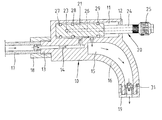
- FIG. 4 is similar to FIG. 3 except for showing the valve in a position for pumping air through an ultra-high pressure nozzle;
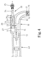
- FIG. 5 is a cross-sectional view of a valve according to a second embodiment of the present invention in communication with a flexible pipe extending from a pump, showing the valve in a position for pumping air through an ordinary nozzle;
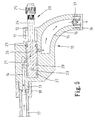
- FIG. 6 is similar to FIG. 5 except for showing the valve in a position for pumping air through an ultra-high pressure nozzle;
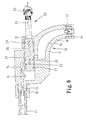
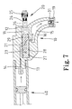
- FIG. 7 is similar to FIG. 5 except for showing the valve directly connected with a cylinder of a pump
- FIG. 8 is similar to FIG. 7 except for showing the valve in a position for pumping air through an ultra-high pressure nozzle;
- FIG. 9 is a cross-sectional view of a valve according to a third embodiment of the present invention in communication with a flexible pipe extending from a pump, showing the valve in a position for pumping air through an ordinary nozzle;
- FIG. 10 is similar to FIG. 9 except for showing the valve in a position for pumping air through an ultra-high pressure nozzle;
- FIG. 11 is similar to FIG. 9 except for showing the valve directly connected with a cylinder of a pump.
- FIG. 12 is similar to FIG. 11 except for showing the valve in a position for pumping air through an ultra-high pressure nozzle;
- a valve according to a first embodiment of the present invention includes a housing 10 , an ordinary nozzle 31 , an ultra-high pressure nozzle 32 and a switch 20 .
- the housing 10 defines a chamber 11 , a hole 12 communicated with the chamber 11 , an inlet channel 14 in communication with the chamber 11 and an outlet channel 15 in communication with the chamber 11 .
- the inlet channel 14 extends through a joint 13 projecting from the housing 10 and includes a first end this is open to the external of the housing 10 and a second end that is open to the chamber 11 .
- the joint 13 includes a root and a tip thinner than the root.
- the tip of the joint 13 can be inserted in an end of a flexible pipe 17 leading from a pump (not shown).
- a pump not shown
- the outlet channel 15 extends through a joint 16 projecting from the housing 10 and includes a first end that is open to the chamber 11 and a second end that is open to the external of the housing 10 .
- the ordinary nozzle 31 is received in the second end of the outlet channel 15 .
- a ring 19 is engaged with an end of the joint 16 , thus retaining the ordinary nozzle 31 in the second end of the outlet channel 15 .
- the switch 20 includes a piston 21 and a rod 24 projecting from the piston 21 .
- the piston 21 is movably received in the chamber 11 .
- the rod 24 is inserted through the hole 12 .
- the ultra-high pressure nozzle 32 is secured to an end of the rod 24 that is exposed to the external of the housing 10 .
- the periphery of the piston 21 defines a hole 23 .
- the switch 20 defines an outlet channel 26 extending in a radial direction from the hole 23 .
- the outlet channel 26 turns and extends axially in the piston 21 and through the rod 24 .
- Rings 27 , 28 and 29 are respectively received in three annular grooves (not numbered) defined in the periphery of the piston 21 .
- the rings 27 , 28 and 29 all contact the wall of the chamber 11 , thus partitioning the chamber 11 into several regions that are not communication with one another.
- the hole 23 is located between the rings 27 and 28 .
- FIG. 1 shows the valve in a first position where air can be pumped through the ordinary nozzle 31 .
- the second end of the inlet channel 14 and the first end of the outlet channel 15 are located between the rings 28 and 29 .
- the inlet channel 14 is communicated with the outlet channel 15 through a region of the chamber 11 confined between the rings 28 and 29 .
- the second end of the inlet channel 14 is not located between the rings 27 and 28 .
- the inlet channel 14 is not communicated with the outlet channel 26 through a region of the chamber 11 confined between the rings 27 and 28 .
- the ordinary nozzle 31 can be engaged with an inlet of a tire.
- air can be provided from the pump to the tire through the ordinary nozzle 31 of the valve.
- FIG. 2 shows the valve in a second position where air can be pumped through the ultra-high pressure nozzle 32 .
- the second end of the inlet channel 14 is located between the rings 27 and 28 .
- the inlet channel 14 is communicated with the outlet channel 26 through the region of the chamber 11 confined between the rings 27 and 28 .
- the first end of the outlet channel 15 is located outside the region of the chamber 11 confined between the rings 27 and 28 .
- the inlet channel 14 is not communicated with the outlet channel 15 .
- the ultra-high pressure nozzle 32 can be engaged with an inlet of a pneumatically adjustable cushion.
- air can be provided from the pump to the pneumatically adjustable cushion through the ultra-high pressure nozzle 32 of the valve.
- the joint 13 of the valve is directly engaged with a cylinder 40 of the pump instead of communication through the flexible pipe 17 .
- FIGS. 5 ⁇ 8 a valve according to a second embodiment of the present invention is shown.
- the second embodiment is identical to the first embodiment except that the joints 13 and 16 are located on two opposite sides of the chamber 11 .
- FIGS. 9 ⁇ 12 show a valve according to a third embodiment of the present invention.
- the third embodiment uses a housing 10 ′ and a switch 50 in place of the housing 10 and the switch 20 .
- the housing 10 ′ defines an inlet channel 14 ′ and an outlet channel 15 ′ instead of the inlet channel 14 and the outlet channel 15 .
- the housing 10 ′ defines a cylindrical chamber 52 and an outlet channel 53 .
- the cylindrical chamber 52 is in communication with the chamber 11 through the outlet channel 53 .
- the inlet channel 14 ′ is in communication with the cylindrical chamber 52 instead of the chamber 11 .
- the outlet channel 15 ′ includes a first end that is open to the cylindrical chamber 52 instead of the chamber 11 .
- the switch 50 is shaped as a shaft defining a transverse channel 51 . The switch 50 is inserted and can be rotated in the cylindrical chamber 52 .
- Third embodiment uses a core 21 ′ instead of the piston 21 .
- the core 21 ′ is identical to the piston 21 except for defining only two annular grooves for receiving only two rings 27 and 28 . In operation, the core 21 ′ does not slide in the chamber 11 because it is not a component of a switch.
- FIG. 9 shows the valve in a position wherein air can be pumped through the ordinary nozzle 31 .
- the second end of the inlet channel 14 is in communication with the first end of the outlet channel 15 through the channel 51 .
- FIG. 10 shows the valve in a second position where air can be pumped through the ultra-high pressure nozzle 32 .
- the second end of the inlet channel 14 is in communication with the outlet channel 53 through the channel 51 .
- the channel 53 is communicated with the outlet channel 26 through the region of the chamber 11 confined between the rings 27 and 28 .
- the joint 13 of the valve is directly engaged with a cylinder 40 of the pump instead of through the flexible pipe 17 .
Abstract
A valve includes a housing, a first nozzle, a second nozzle and a switch. The housing defines an inlet channel for communication with a pump, a chamber in communication with the inlet channel, a first outlet channel in communication with the chamber and a second outlet channel in communication with the chamber. The first nozzle is in communication with the first outlet channel. The second nozzle is in communication with the second outlet channel. The switch is received in the chamber and movable between a first position where the inlet is communicated with the first outlet channel through the chamber and a second position where the inlet is communicated with the second outlet channel through the chamber. The first nozzle is for engagement with an inlet of a tire. The second nozzle is for engagement with an inlet of a pneumatically adjustable cushion.
Description
- 1. Field of Invention
- The present invention is related to a valve for a pump.
- 2. Related Prior Art
- Many drivers carry portable pumps in their cars for pumping tires. From such a portable pump extends a flexible pipe connected with a nozzle for engagement with an inlet of a tire. Now, many cars are equipped with pneumatically adjustable cushions. Air can be pumped into such a cushion so as to extend its length, thus rendering the cushion “softer.” Of course, air can be released from the cushion so as to reduce its length, thus rendering the cushion “harder.” For a car equipped with pneumatically adjustable cushions, a portable pump is responsible for pumping the tires and the cushions. However, a cushion requires a higher pressure than a tire does. It is found that a nozzle designed for engagement with an inlet of a tire often fails engagement with an inlet of a cushion for being unable to sustain an ultra-high pressure during pumping. To avoid this problem, a portable pump may be equipped with an additional nozzle that is designed for engagement with an inlet of a cushion and can sustain an ultra-high pressure during pumping. However, such an ultra-high pressure nozzle is often forgotten or lost, thus rendering it impossible to pump the cushion. Besides, it is always troublesome to replace an ordinary nozzle with an ultra-high pressure nozzle and vice versa. Moreover, engagement of the ordinary or ultra-high pressure nozzle with the flexible pipe leading from the pump becomes slack after replacement takes place for some times.
- The present invention is intended to obviate or at least alleviate the problems encountered in prior art.
- It is the primary objective of the present invention to provide a valve for tight engagement with an inlet of a tire or pneumatically adjustable cushion.
- According to the present invention, a valve includes a housing, a first nozzle, a second nozzle and a switch. The housing defines an inlet channel for communication with a pump, a chamber in communication with the inlet channel, a first outlet channel in communication with the chamber and a second outlet channel in communication with the chamber. The first nozzle is in communication with the first outlet channel. The second nozzle is in communication with the second outlet channel. The switch is received in the chamber and movable between a first position where the inlet is communicated with the first outlet channel through the chamber and a second position where the inlet is communicated with the second outlet channel through the chamber. The first nozzle is for engagement with an inlet of a tire. The second nozzle is for engagement with an inlet of a pneumatically adjustable cushion.
- In a first aspect, the switch can slide. The switch includes a piston and a rod extending from the piston, wherein the piston blocks the inlet from the second outlet channel in the first position, wherein the piston blocks the inlet from the first outlet channel in the second position. The switch defines the second outlet channel. The second outlet channel includes a first end in the piston and a second end in the rod. The inlet channel includes a first end for communication with the pump and a second end communicated with the chamber. The first outlet channel includes a first end communicated with the chamber and a second end communicated with first nozzle. The valve includes a ring mounted on the piston so as to divide the chamber into two regions. In the first position, the second end of the inlet channel and the first end of the first outlet channel are in a region of the chamber while the first end of the second outlet channel is in the other region of the chamber. In the second position, the second end of the inlet channel and the first end of the second outlet channel are in a region of the chamber while the first end of the first outlet channel is in the other region of the chamber.
- In a second aspect, the switch can rotate in the chamber. The switch defines a channel through which the inlet channel is communicated with the first outlet channel in the first position and with the second outlet channel in the second position.
- Other objects, advantages, and novel features of the invention will become more apparent from the following detailed description when taken in conjunction with the attached drawings.
- The present invention is described through detailed illustration of embodiments referring to the attached drawings wherein:
- FIG. 1 is a cross-sectional view of a valve according to a first embodiment of the present invention in communication with a flexible pipe extending from a pump, showing the valve in a position for pumping air through an ordinary nozzle;
- FIG. 2 is similar to FIG. 1 except for showing the valve in a position for pumping air through an ultra-high pressure nozzle;
- FIG. 3 is similar to FIG. 1 except for showing the valve directly connected with a cylinder of a pump;
- FIG. 4 is similar to FIG. 3 except for showing the valve in a position for pumping air through an ultra-high pressure nozzle;
- FIG. 5 is a cross-sectional view of a valve according to a second embodiment of the present invention in communication with a flexible pipe extending from a pump, showing the valve in a position for pumping air through an ordinary nozzle;
- FIG. 6 is similar to FIG. 5 except for showing the valve in a position for pumping air through an ultra-high pressure nozzle;
- FIG. 7 is similar to FIG. 5 except for showing the valve directly connected with a cylinder of a pump;
- FIG. 8 is similar to FIG. 7 except for showing the valve in a position for pumping air through an ultra-high pressure nozzle;
- FIG. 9 is a cross-sectional view of a valve according to a third embodiment of the present invention in communication with a flexible pipe extending from a pump, showing the valve in a position for pumping air through an ordinary nozzle;
- FIG. 10 is similar to FIG. 9 except for showing the valve in a position for pumping air through an ultra-high pressure nozzle;
- FIG. 11 is similar to FIG. 9 except for showing the valve directly connected with a cylinder of a pump; and
- FIG. 12 is similar to FIG. 11 except for showing the valve in a position for pumping air through an ultra-high pressure nozzle;
- Referring to FIGS. 1 and 2, a valve according to a first embodiment of the present invention includes a
housing 10, anordinary nozzle 31, an ultra-highpressure nozzle 32 and aswitch 20. - The
housing 10 defines achamber 11, ahole 12 communicated with thechamber 11, aninlet channel 14 in communication with thechamber 11 and anoutlet channel 15 in communication with thechamber 11. Theinlet channel 14 extends through a joint 13 projecting from thehousing 10 and includes a first end this is open to the external of thehousing 10 and a second end that is open to thechamber 11. Thejoint 13 includes a root and a tip thinner than the root. The tip of thejoint 13 can be inserted in an end of aflexible pipe 17 leading from a pump (not shown). Thus, air can be provided from the pump to the valve. A ring secured to the end of theflexible pipe 17 can be engaged with the root of thejoint 13. Thus, communication of the pump with the valve is ensured. - The
outlet channel 15 extends through a joint 16 projecting from thehousing 10 and includes a first end that is open to thechamber 11 and a second end that is open to the external of thehousing 10. Theordinary nozzle 31 is received in the second end of theoutlet channel 15. Aring 19 is engaged with an end of the joint 16, thus retaining theordinary nozzle 31 in the second end of theoutlet channel 15. - The
switch 20 includes apiston 21 and arod 24 projecting from thepiston 21. Thepiston 21 is movably received in thechamber 11. Therod 24 is inserted through thehole 12. Theultra-high pressure nozzle 32 is secured to an end of therod 24 that is exposed to the external of thehousing 10. - The periphery of the
piston 21 defines ahole 23. Theswitch 20 defines anoutlet channel 26 extending in a radial direction from thehole 23. Theoutlet channel 26 turns and extends axially in thepiston 21 and through therod 24. -
Rings piston 21. Therings chamber 11, thus partitioning thechamber 11 into several regions that are not communication with one another. Thehole 23 is located between therings - FIG. 1 shows the valve in a first position where air can be pumped through the
ordinary nozzle 31. In the first position, the second end of theinlet channel 14 and the first end of theoutlet channel 15 are located between therings inlet channel 14 is communicated with theoutlet channel 15 through a region of thechamber 11 confined between therings inlet channel 14 is not located between therings inlet channel 14 is not communicated with theoutlet channel 26 through a region of thechamber 11 confined between therings ordinary nozzle 31 can be engaged with an inlet of a tire. Thus, air can be provided from the pump to the tire through theordinary nozzle 31 of the valve. - FIG. 2 shows the valve in a second position where air can be pumped through the
ultra-high pressure nozzle 32. In the second position, the second end of theinlet channel 14 is located between therings inlet channel 14 is communicated with theoutlet channel 26 through the region of thechamber 11 confined between therings outlet channel 15 is located outside the region of thechamber 11 confined between therings inlet channel 14 is not communicated with theoutlet channel 15. Theultra-high pressure nozzle 32 can be engaged with an inlet of a pneumatically adjustable cushion. Thus, air can be provided from the pump to the pneumatically adjustable cushion through theultra-high pressure nozzle 32 of the valve. - Referring to FIGS. 3 and 4, the joint 13 of the valve is directly engaged with a
cylinder 40 of the pump instead of communication through theflexible pipe 17. - Referring to FIGS. 5˜8, a valve according to a second embodiment of the present invention is shown. The second embodiment is identical to the first embodiment except that the
joints chamber 11. - FIGS. 9˜12 show a valve according to a third embodiment of the present invention. The third embodiment uses a
housing 10′ and aswitch 50 in place of thehousing 10 and theswitch 20. Thehousing 10′ defines aninlet channel 14′ and anoutlet channel 15′ instead of theinlet channel 14 and theoutlet channel 15. Thehousing 10′ defines acylindrical chamber 52 and anoutlet channel 53. Thecylindrical chamber 52 is in communication with thechamber 11 through theoutlet channel 53. Theinlet channel 14′ is in communication with thecylindrical chamber 52 instead of thechamber 11. Theoutlet channel 15′ includes a first end that is open to thecylindrical chamber 52 instead of thechamber 11. Theswitch 50 is shaped as a shaft defining atransverse channel 51. Theswitch 50 is inserted and can be rotated in thecylindrical chamber 52. - Third embodiment uses a core 21′ instead of the
piston 21. The core 21′ is identical to thepiston 21 except for defining only two annular grooves for receiving only tworings chamber 11 because it is not a component of a switch. - FIG. 9 shows the valve in a position wherein air can be pumped through the
ordinary nozzle 31. In the first position, the second end of theinlet channel 14 is in communication with the first end of theoutlet channel 15 through thechannel 51. - FIG. 10 shows the valve in a second position where air can be pumped through the
ultra-high pressure nozzle 32. In the second position, the second end of theinlet channel 14 is in communication with theoutlet channel 53 through thechannel 51. Thechannel 53 is communicated with theoutlet channel 26 through the region of thechamber 11 confined between therings - Referring to FIGS. 11 and 12, the joint 13 of the valve is directly engaged with a
cylinder 40 of the pump instead of through theflexible pipe 17. - The present invention has been described through detailed illustration of several embodiments. Those skilled in the art can derive many variations from the embodiments without departing from the scope of the present invention. Therefore, the embodiments shall not limit the scope of the present invention that can only be defined in the attached claims.
Claims (10)
1. A valve including:
a housing defining an inlet channel for communication with a pump, a chamber in communication with the inlet channel, a first outlet channel in communication with the chamber and a second outlet channel in communication with the chamber;
a first nozzle in communication with the first outlet channel;
a second nozzle in communication with the second outlet channel; and
a switch received in the chamber and movable between a first position where the inlet is communicated with the first outlet channel through the chamber and a second position where the inlet is communicated with the second outlet channel through the chamber.
2. The valve according to claim 1 wherein the first nozzle is for engagement with an inlet of a tire.
3. The valve according to claim 1 wherein the second nozzle is for engagement with an inlet of a pneumatically adjustable cushion.
4. The valve according to claim 1 wherein the switch can slide.
5. The valve according to claim 4 wherein the switch includes a piston and a rod extending from the piston, wherein the piston blocks the inlet from the second outlet channel in the first position, wherein the piston blocks the inlet from the first outlet channel in the second position.
6. The valve according to claim 5 wherein the switch defines the second outlet channel, wherein the second outlet channel includes a first end in the piston and a second end in the rod.
7. The valve according to claim 6 wherein the inlet channel includes a first end for communication with the pump and a second end in communication with the chamber, wherein the first outlet channel includes a first end in communication with the chamber and a second end in communication with first nozzle.
8. The valve according to claim 7 including a ring mounted on the piston so as to divide the chamber into two regions, wherein the second end of the inlet channel and the first end of the first outlet channel are in a region of the chamber while the first end of the second outlet channel is in the other region of the chamber in the first position, wherein the second end of the inlet channel and the first end of the second outlet channel are in a region of the chamber while the first end of the first outlet channel is in the other region of the chamber in the second position.
9. The valve according to claim 1 wherein the switch can rotate.
10. The valve according to claim 9 wherein the switch defines a channel through which the inlet channel is communicated with the first outlet channel in the first position and with the second outlet channel in the second position.
Priority Applications (3)
| Application Number | Priority Date | Filing Date | Title |
|---|---|---|---|
| US10/126,135 US20030196699A1 (en) | 2002-04-19 | 2002-04-19 | Valve for pump |
| US11/035,820 US7195030B2 (en) | 2002-04-19 | 2005-01-14 | Bicycle pump valve |
| US11/052,402 US7178549B2 (en) | 2002-04-19 | 2005-02-07 | Valve coupling device for pump |
Applications Claiming Priority (1)
| Application Number | Priority Date | Filing Date | Title |
|---|---|---|---|
| US10/126,135 US20030196699A1 (en) | 2002-04-19 | 2002-04-19 | Valve for pump |
Related Parent Applications (1)
| Application Number | Title | Priority Date | Filing Date |
|---|---|---|---|
| US11/035,820 Continuation-In-Part US7195030B2 (en) | 2002-04-19 | 2005-01-14 | Bicycle pump valve |
Related Child Applications (2)
| Application Number | Title | Priority Date | Filing Date |
|---|---|---|---|
| US11/035,820 Continuation-In-Part US7195030B2 (en) | 2002-04-19 | 2005-01-14 | Bicycle pump valve |
| US11/052,402 Continuation-In-Part US7178549B2 (en) | 2002-04-19 | 2005-02-07 | Valve coupling device for pump |
Publications (1)
| Publication Number | Publication Date |
|---|---|
| US20030196699A1 true US20030196699A1 (en) | 2003-10-23 |
Family
ID=29214945
Family Applications (1)
| Application Number | Title | Priority Date | Filing Date |
|---|---|---|---|
| US10/126,135 Abandoned US20030196699A1 (en) | 2002-04-19 | 2002-04-19 | Valve for pump |
Country Status (1)
| Country | Link |
|---|---|
| US (1) | US20030196699A1 (en) |
Cited By (1)
| Publication number | Priority date | Publication date | Assignee | Title |
|---|---|---|---|---|
| US20050121077A1 (en) * | 2002-04-19 | 2005-06-09 | Chiang-Pei Chen | Bicycle pump valve |
Citations (14)
| Publication number | Priority date | Publication date | Assignee | Title |
|---|---|---|---|---|
| US1838166A (en) * | 1929-01-25 | 1931-12-29 | Schraders Son Inc | Pressure gauge |
| US2344492A (en) * | 1941-10-15 | 1944-03-21 | Francis W Brubaker | Air nozzle |
| US2474286A (en) * | 1945-03-26 | 1949-06-28 | Quality Appliances Inc | Bubble fountain device |
| US2716998A (en) * | 1949-03-02 | 1955-09-06 | Joseph J Knasko | Combined tire inflating chuck, deflator and blow gun |
| US2869573A (en) * | 1955-06-03 | 1959-01-20 | Alton B Stafford | Combination air nozzle |
| US2880747A (en) * | 1954-11-08 | 1959-04-07 | Duane H Newcomb | Air under pressure distributor |
| US3044491A (en) * | 1958-07-29 | 1962-07-17 | Texas Instruments Inc | Multiport switching valve |
| US3827635A (en) * | 1973-03-16 | 1974-08-06 | A Krakowski | Air hose adapter |
| US3933177A (en) * | 1973-10-23 | 1976-01-20 | The Black And Decker Manufacturing Company | Manually controlled air inflator adaptor |
| US4423741A (en) * | 1980-01-14 | 1984-01-03 | Plasco, Inc. | Midstream sampling of catheterized liquid flow from a body cavity and improved coupling therefor |
| US4921402A (en) * | 1989-05-01 | 1990-05-01 | David C. Nelson | Balloon inflator valve |
| US5785076A (en) * | 1996-05-20 | 1998-07-28 | You; Bae-Jou | Inflating assembly for tire |
| US5855222A (en) * | 1996-09-26 | 1999-01-05 | Jou; Wuu-Cheau | Multi-purpose pneumatic tool |
| US5921269A (en) * | 1997-06-30 | 1999-07-13 | Wu; Scott | Tire inflator |
-
2002
- 2002-04-19 US US10/126,135 patent/US20030196699A1/en not_active Abandoned
Patent Citations (14)
| Publication number | Priority date | Publication date | Assignee | Title |
|---|---|---|---|---|
| US1838166A (en) * | 1929-01-25 | 1931-12-29 | Schraders Son Inc | Pressure gauge |
| US2344492A (en) * | 1941-10-15 | 1944-03-21 | Francis W Brubaker | Air nozzle |
| US2474286A (en) * | 1945-03-26 | 1949-06-28 | Quality Appliances Inc | Bubble fountain device |
| US2716998A (en) * | 1949-03-02 | 1955-09-06 | Joseph J Knasko | Combined tire inflating chuck, deflator and blow gun |
| US2880747A (en) * | 1954-11-08 | 1959-04-07 | Duane H Newcomb | Air under pressure distributor |
| US2869573A (en) * | 1955-06-03 | 1959-01-20 | Alton B Stafford | Combination air nozzle |
| US3044491A (en) * | 1958-07-29 | 1962-07-17 | Texas Instruments Inc | Multiport switching valve |
| US3827635A (en) * | 1973-03-16 | 1974-08-06 | A Krakowski | Air hose adapter |
| US3933177A (en) * | 1973-10-23 | 1976-01-20 | The Black And Decker Manufacturing Company | Manually controlled air inflator adaptor |
| US4423741A (en) * | 1980-01-14 | 1984-01-03 | Plasco, Inc. | Midstream sampling of catheterized liquid flow from a body cavity and improved coupling therefor |
| US4921402A (en) * | 1989-05-01 | 1990-05-01 | David C. Nelson | Balloon inflator valve |
| US5785076A (en) * | 1996-05-20 | 1998-07-28 | You; Bae-Jou | Inflating assembly for tire |
| US5855222A (en) * | 1996-09-26 | 1999-01-05 | Jou; Wuu-Cheau | Multi-purpose pneumatic tool |
| US5921269A (en) * | 1997-06-30 | 1999-07-13 | Wu; Scott | Tire inflator |
Cited By (2)
| Publication number | Priority date | Publication date | Assignee | Title |
|---|---|---|---|---|
| US20050121077A1 (en) * | 2002-04-19 | 2005-06-09 | Chiang-Pei Chen | Bicycle pump valve |
| US7195030B2 (en) | 2002-04-19 | 2007-03-27 | Chiang-Pei Chen | Bicycle pump valve |
Similar Documents
| Publication | Publication Date | Title |
|---|---|---|
| US9869306B2 (en) | Multistage air pump | |
| US6514058B1 (en) | Compressor having an improved valved piston device | |
| US6260572B1 (en) | Valve-coupling device for an inflation device | |
| US7661934B2 (en) | Universal air pump | |
| US5449278A (en) | Double action piston having plural annular check valves | |
| US7195030B2 (en) | Bicycle pump valve | |
| US5902097A (en) | Pumping device with a clamping nozzle for various valves | |
| US20050191193A1 (en) | Air compressor for tire inflating combination | |
| US20070215636A1 (en) | Pumping joint | |
| US6120265A (en) | Two-stroke operable pump | |
| KR20180033531A (en) | Compressor with crankshaft and insert | |
| US7309034B2 (en) | Air nozzle with a central tube movably received therein to adapt to various positions of a pin in an object to be inflated | |
| US1964679A (en) | Compressor | |
| US6827096B1 (en) | Relief valve | |
| US6695595B2 (en) | Pump for pumping at two pressures | |
| US20030196699A1 (en) | Valve for pump | |
| CN107667239B (en) | The piston component of feather valve for air compressor | |
| EP1437508B1 (en) | Valved piston compressor | |
| WO2015151310A1 (en) | Throttle valve | |
| US20050042123A1 (en) | Apparatus for inflating and deflating | |
| US5624242A (en) | Hand air pump for different types of valves | |
| US20020178907A1 (en) | Air compressor having a smooth and stable structure | |
| US2299172A (en) | Rotary hose coupling assembly | |
| JP6560098B2 (en) | Hydraulic down-the-hole drill accumulator | |
| US11565556B1 (en) | Tire valve assembly |
Legal Events
| Date | Code | Title | Description |
|---|---|---|---|
| STCB | Information on status: application discontinuation |
Free format text: ABANDONED -- FAILURE TO RESPOND TO AN OFFICE ACTION |