US20030196884A1 - Batch thermolytic distillation of carbonaceous material - Google Patents
Batch thermolytic distillation of carbonaceous material Download PDFInfo
- Publication number
- US20030196884A1 US20030196884A1 US10/417,751 US41775103A US2003196884A1 US 20030196884 A1 US20030196884 A1 US 20030196884A1 US 41775103 A US41775103 A US 41775103A US 2003196884 A1 US2003196884 A1 US 2003196884A1
- Authority
- US
- United States
- Prior art keywords
- reactor
- bath
- molten material
- molten
- reactor bath
- Prior art date
- Legal status (The legal status is an assumption and is not a legal conclusion. Google has not performed a legal analysis and makes no representation as to the accuracy of the status listed.)
- Granted
Links
Images


Classifications
-
- C—CHEMISTRY; METALLURGY
- C10—PETROLEUM, GAS OR COKE INDUSTRIES; TECHNICAL GASES CONTAINING CARBON MONOXIDE; FUELS; LUBRICANTS; PEAT
- C10B—DESTRUCTIVE DISTILLATION OF CARBONACEOUS MATERIALS FOR PRODUCTION OF GAS, COKE, TAR, OR SIMILAR MATERIALS
- C10B53/00—Destructive distillation, specially adapted for particular solid raw materials or solid raw materials in special form
-
- C—CHEMISTRY; METALLURGY
- C10—PETROLEUM, GAS OR COKE INDUSTRIES; TECHNICAL GASES CONTAINING CARBON MONOXIDE; FUELS; LUBRICANTS; PEAT
- C10B—DESTRUCTIVE DISTILLATION OF CARBONACEOUS MATERIALS FOR PRODUCTION OF GAS, COKE, TAR, OR SIMILAR MATERIALS
- C10B47/00—Destructive distillation of solid carbonaceous materials with indirect heating, e.g. by external combustion
- C10B47/02—Destructive distillation of solid carbonaceous materials with indirect heating, e.g. by external combustion with stationary charge
- C10B47/14—Destructive distillation of solid carbonaceous materials with indirect heating, e.g. by external combustion with stationary charge with the aid of hot liquids, e.g. molten salts
-
- C—CHEMISTRY; METALLURGY
- C10—PETROLEUM, GAS OR COKE INDUSTRIES; TECHNICAL GASES CONTAINING CARBON MONOXIDE; FUELS; LUBRICANTS; PEAT
- C10B—DESTRUCTIVE DISTILLATION OF CARBONACEOUS MATERIALS FOR PRODUCTION OF GAS, COKE, TAR, OR SIMILAR MATERIALS
- C10B49/00—Destructive distillation of solid carbonaceous materials by direct heating with heat-carrying agents including the partial combustion of the solid material to be treated
- C10B49/14—Destructive distillation of solid carbonaceous materials by direct heating with heat-carrying agents including the partial combustion of the solid material to be treated with hot liquids, e.g. molten metals
-
- C—CHEMISTRY; METALLURGY
- C10—PETROLEUM, GAS OR COKE INDUSTRIES; TECHNICAL GASES CONTAINING CARBON MONOXIDE; FUELS; LUBRICANTS; PEAT
- C10B—DESTRUCTIVE DISTILLATION OF CARBONACEOUS MATERIALS FOR PRODUCTION OF GAS, COKE, TAR, OR SIMILAR MATERIALS
- C10B53/00—Destructive distillation, specially adapted for particular solid raw materials or solid raw materials in special form
- C10B53/02—Destructive distillation, specially adapted for particular solid raw materials or solid raw materials in special form of cellulose-containing material
-
- C—CHEMISTRY; METALLURGY
- C10—PETROLEUM, GAS OR COKE INDUSTRIES; TECHNICAL GASES CONTAINING CARBON MONOXIDE; FUELS; LUBRICANTS; PEAT
- C10B—DESTRUCTIVE DISTILLATION OF CARBONACEOUS MATERIALS FOR PRODUCTION OF GAS, COKE, TAR, OR SIMILAR MATERIALS
- C10B53/00—Destructive distillation, specially adapted for particular solid raw materials or solid raw materials in special form
- C10B53/07—Destructive distillation, specially adapted for particular solid raw materials or solid raw materials in special form of solid raw materials consisting of synthetic polymeric materials, e.g. tyres
-
- Y—GENERAL TAGGING OF NEW TECHNOLOGICAL DEVELOPMENTS; GENERAL TAGGING OF CROSS-SECTIONAL TECHNOLOGIES SPANNING OVER SEVERAL SECTIONS OF THE IPC; TECHNICAL SUBJECTS COVERED BY FORMER USPC CROSS-REFERENCE ART COLLECTIONS [XRACs] AND DIGESTS
- Y02—TECHNOLOGIES OR APPLICATIONS FOR MITIGATION OR ADAPTATION AGAINST CLIMATE CHANGE
- Y02E—REDUCTION OF GREENHOUSE GAS [GHG] EMISSIONS, RELATED TO ENERGY GENERATION, TRANSMISSION OR DISTRIBUTION
- Y02E50/00—Technologies for the production of fuel of non-fossil origin
- Y02E50/10—Biofuels, e.g. bio-diesel
-
- Y—GENERAL TAGGING OF NEW TECHNOLOGICAL DEVELOPMENTS; GENERAL TAGGING OF CROSS-SECTIONAL TECHNOLOGIES SPANNING OVER SEVERAL SECTIONS OF THE IPC; TECHNICAL SUBJECTS COVERED BY FORMER USPC CROSS-REFERENCE ART COLLECTIONS [XRACs] AND DIGESTS
- Y02—TECHNOLOGIES OR APPLICATIONS FOR MITIGATION OR ADAPTATION AGAINST CLIMATE CHANGE
- Y02P—CLIMATE CHANGE MITIGATION TECHNOLOGIES IN THE PRODUCTION OR PROCESSING OF GOODS
- Y02P20/00—Technologies relating to chemical industry
- Y02P20/141—Feedstock
- Y02P20/143—Feedstock the feedstock being recycled material, e.g. plastics
Definitions
- the invention relates generally to transformation of carbonaceous material such as waste wood and shredded rubber tires into liquid hydrocarbons and char.
- U.S. Pat. No. 5,605,551 to Scott et al. discloses a process for thermal conversion of biomass such as wood to liquids by pyrolysis in a fluidized bed in which the conveying gas contains low and carefully controlled amounts of oxygen.
- U.S. Pat. No. 5,584,970 to Schmalfeld et al. discloses a process for thermal conversion of biomass such as wood to charcoal, the process involves drying the wood in a first flow of hot gas and then carbonizing the wood in a second flow of hot gas.
- a principal object of the present invention is to provide an improved process and distillation unit for on-site thermal conversion of scrap carbonaceous material including wood, shredded rubber tires or other organic matter into commercially desirable products in a way that minimizes the disposal problems faced by the owners of sites that create significant quantities of scrap carbonaceous material.
- scrap carbonaceous material is immersed in molten material and thereby converted to gaseous hydrocarbons and char; to further provide such a process wherein scrap carbonaceous material is thermally converted to vapor forms that may be condensed and further separated to commercially valuable hydrocarbons and char; to further provide such a process wherein residual solids from the thermal conversion, including char, are captured and separated; to further provide such a process wherein a portion of the combustible vapors emitted from the thermal conversion of organic matter is utilized to heat the molten material bath in the reaction bath; to further provide such a process and apparatus that minimizes the risk of exposure of operating personnel to the high temperatures of the molten material; to further provide such a process wherein the self-ignition of combustible products is prevented by maintaining an effective barrier between hot combustible products and air; to further provide such a process wherein the process fluids are recycled to minimize both heat loss and release of environmental pollutants; to further provide
- the present invention provides an apparatus and process for batch thermolytic distillation of lump carbonaceous material including waste wood and shredded rubber tires.
- a preferred embodiment of the apparatus includes a distillation unit including a reactor with a reactor bath adapted to hold a molten material selected from a group of molten materials consisting of molten metal and molten salt, a retractable lid, and a basket pivotally mounted within the reactor bath between a pair of opposing reactor bath walls.
- the reactor In a distillation unit intended for side-by-side mounting of multiple units and for receiving a charge of wood from above a first end of the unit, the reactor is located at a first end of the unit.
- the basket is pivotally mounted for tipping the basket from a first position inside the reactor bath in an upright orientation, to a second position partially inside and partially outside the reactor bath in a substantially inverted orientation.
- the preferred embodiment includes at least one hydraulic hold-down clamp attached between reactor and lid.
- the lid includes a perimeter curtain wall having a beveled lower rim shaped to fit a facing beveled rim of the reactor bath, and a perforated screen.
- the reactor further includes an inlet conduit for molten material, an outlet conduit for molten material, and a reactor gas outlet; and the unit further includes a reservoir for storing molten material, the reservoir having a supply conduit coupled to supply molten material to the reactor inlet conduit, and a return conduit coupled to accept molten material from the reactor outlet conduit.
- the base of the reactor is higher than the top of the reservoir by approximately three feet.
- the reservoir includes two compartments with a check valve connecting them, a pressurized air inlet, and a controllable vent.
- the reservoir also includes an excess-air heater, and a corrugated heat exchanger.
- the distillation unit further comprises a steam generator and a steam generator flue.
- the reservoir further includes an excess-air heater and an excess air heater flue.
- the excess-air heater flue is coupled to deliver excess-air heater flue gas to the steam generator.
- the excess-air heater flue is coupled to deliver excess-air heater flue gas to the steam generator flue via a bypass flue and a control valve.
- the reactor bath includes a wall conduit.
- the distillation unit further includes a condenser with a particulates trap having a pressure region below atmospheric pressure.
- the present invention also provides a process for batch thermolytic distillation of carbonaceous material such as lump wood or shredded rubber tires.
- the process includes rotating a porous basket into a reactor bath; putting a charge of lump carbonaceous material into the basket; closing a retractable lid onto the reactor bath; and filling the reactor bath with molten material to produce gas and char by thermolytic conversion of the charge.
- the molten material is preferably molten tin at a temperature of approximately 851° F. (455° C.).
- Rotating the porous basket into the reactor bath includes rotating the basket about an axis within the reactor bath.
- Closing the lid includes translating the lid and lowering the lid.
- the preferred embodiment further includes forcibly holding the lid closed while the temperature in the reactor bath is above a predetermined temperature.
- Filling the reactor with molten material includes moving molten material by gravity or by air pressure.
- the process preferably includes moving molten material through the basket for a predetermined period of time after filling the reactor bath with molten material, and raising the surface of the molten material at a sufficient rate to ensure that steam given off from newly heated charge effectively prevents oxygen from reacting with newly formed char.
- the molten material is preferably heated using an excess air heater using combustible fluids produced in the reactor bath and further using heat from hot air recovered during condensing to heat the molten material.
- a flow of molten material through the reactor bath is preferably maintained during thermolytic distillation.
- the process further includes draining the reactor bath of molten material while the lid is closed; quenching the char in the reactor bath with steam; opening the lid; and removing the char from the basket.
- Draining the reactor bath includes driving superheated steam into the reactor bath. Superheated steam is produced at a temperature of about 228° F., and a pressure of about 20 psi, using flue gas from an excess air heater. The char is quenched with steam until the temperature of the char is below a self-ignition temperature. Opening the lid includes raising the lid using hydraulic actuators, and retracting the lid using a drive screw to place the lid under a lip of a loading platform. Removing the char from the basket includes rotating the basket about an axis within the reactor bath.
- the process further includes condensing, in a pressure region below atmospheric pressure, a mixture of gas from thermolytic conversion of the charge and steam introduced in quenching.
- FIG. 1 is a schematic representation of a first embodiment of the distillation unit of the invention.
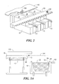
- FIG. 2 is a partial cut-away perspective view of multiple distillation units of FIG. 1 between an on-site loading platform and a belt conveyor system.
- FIG. 3A is a cut-away elevation view of the reactor, the loading platform, and the reactor lid of FIG. 1, illustrating the retraction and replacement of the lid.
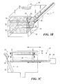
- FIG. 3B is a perspective view of the lid carrier and basket carrier of the embodiment of FIG. 1.
- FIG. 3C is a schematic elevation view of the lid carrier and basket carrier of FIG. 3B, giving more detail.
- FIG. 3D is a cut-away perspective view of the basket carrier and pivot plate of the embodiment of FIG. 1.
- FIG. 4 is a schematic elevation view of the reactor, the loading platform, and the basket of FIG. 1, illustrating the loading of the basket with wood.
- FIG. 5 is a schematic elevation view of a portion of FIG. 1, showing the basket tipping the char onto the conveyor system.
- FIG. 6 is a schematic perspective view of a portion of the embodiment of FIG. 1, illustrating the flow of molten metal through the reservoir and through the reactor.
- FIG. 7A is a schematic perspective view of a portion of the reservoir, showing the excess-air heater.
- FIG. 7B is an enlarged portion of FIG. 7A, giving detail of the excess-air heater.
- FIG. 8 is a schematic perspective view of the condenser of FIG. 1.
- the invention provides a process and a distillation unit for converting carbonaceous material into useful product by thermolysis (dissociation of a compound by heat in a bath of molten metal, or molten salt, in the absence of oxygen).
- thermolysis dissociation of a compound by heat in a bath of molten metal, or molten salt, in the absence of oxygen.
- the invention provides a process for converting wood to wood-petrol and char by immersion in molten tin at a temperature of approximately 851° F. (455° C.).
- the invention provides a process for converting shredded rubber tires to hydrocarbons and char by immersion in molten tin. Shredded rubber tires may be converted at substantially the same temperature at which wood is converted, approximately 851 ° F. (455° C.).
- Distillation unit 11 of the preferred embodiment which includes frame 10 , is shown in FIG. 1 between loading platform 110 and belt conveyor system 120 .
- FIG. 1 shows reactor bath 19 of reactor 20 in the reaction phase containing molten tin 21 and porous basket 30 , with retractable lid 40 on top of the reactor.
- the front of distillation unit 11 is shown beneath loading platform 110 .
- the back of the distillation unit is shown beneath belt conveyor system 120 . “Front to back” defines a long axis of the distillation unit.
- Multiple distillation units, 11 , 12 , 13 , etc. may be mounted side-by-side, as shown in FIG. 2, to match the throughput requirements of a given site.
- FIG. 3A The loading of reactor 20 with a charge of lump wood 100 from the loading platform is shown in FIG. 4.
- FIG. 5 The tipping of char 130 from basket 30 onto the conveyor system is shown in FIG. 5.
- the reactor is fabricated from stainless steel AISI 310 or other material resistant to the temperature and chemicals involved in the process.
- FIG. 1 shows reactor 20 having a reactor gas outlet 25 , an inlet conduit 26 , and an outlet conduit 27 .
- the purpose of basket 30 is to contain wood in the reactor before and during the reaction phase and to carry char out of the reactor after the reaction phase.
- the walls of the basket are made of heavy wire mesh or heavy pressed steel having multiple apertures 38 which allow the molten tin to penetrate the basket and contact the lump wood.
- the basket is 60 inches long, 36 inches deep and 60 inches wide. Apertures may be formed by the wire mesh construction shown in FIG. 3B or may be narrow slits as in expanded pressed steel. In either case the apertures need to be small enough in at least one dimension to prevent pieces of wood having small cross section from falling out of the basket through the apertures.
- the wood to be processed has a maximum cross section to ensure that all of the wood is fully cooked in the fixed immersion time that the apparatus is designed to provide.
- FIG. 3D shows the basket carrier of the embodiment of FIG. 1, and pivot bar 32 and pivot plate 37 which together define a pivot axis within reactor bath 19 .
- pivot bar end 33 extends though side wall 28 and pivot plate 37 , and is attached to the lower end of basket carrier lever 36 .
- Pivot plate 37 provides a pressure seal bearing to maintain the integrity of reactor vessel 20 .
- basket carrier actuator cylinder 34 pulls basket carrier drive rod 35 down so as to rotate basket carrier lever 36 and basket 30 about the pivot axis.
- FIG. 3D also shows the basket having aperture 38 .
- pivot bar 32 may be supported by a pivot plate wholly within the reactor bath and a rotational drive may be detachably coupled to pivot bar 32 only while the lid is retracted.
- reactor 20 has a double wall 22 , including outer wall 82 and inner wall 83 , that defines a wall conduit 23 .
- the double wall substantially surrounds the reactor. Gas given off in the reactor during the reaction phase flows through wall conduit 23 , thereby providing thermal insulation for the molten tin in the reactor.
- reservoir 50 which stores molten tin for use in the reactor.
- Reservoir 50 has a supply conduit 51 coupled to supply molten tin to the reactor via inlet conduit 26 .
- Reservoir 50 also has a return conduit 52 coupled to accept molten tin from outlet conduit 27 of the reactor.
- reservoir 50 has a first compartment 56 coupled by check valve 107 to a second compartment 57 , a pressurized air inlet 54 , and a controllable vent 55 .
- the top of reservoir 50 is approximately three feet below the base of reactor 20 .
- Reservoir 50 also has a corrugated bottom heat exchanger 53 , and an excess air heater 60 for heating the molten tin in the reservoir.
- Heater 60 has a fuel supply line 61 , and an air blower 62 set for a 10:1 ratio, air to gas, at the burner.
- Hot gas enters heat exchanger 53 at a temperature above 480° C., and leaves at a temperature in the range 310-320° C. via excess-air heater flue 63 .
- a first portion of the gas from flue 63 supplies heat to steam generator 70 .
- Steam generator 70 supplies quenching steam to the reactor during the quenching phase via steam conduit 71 .
- the steam generator receives water from water supply 72 , and heat from a first portion of hot gas from flue 63 . Exhaust from the steam generator at a temperature of approximately 260° C. is vented via flue pipe 73 . A second portion of hot exhaust gases passing through flue 63 is vented via bypass flue pipe 74 and flue pipe 73 , under control of flue pipe control valve 75 . Valve 75 is used to stabilize the temperature of hot gas entering the steam generator.
- Condenser 80 shown in FIG. 8, condenses reactor gas given off in the reactor during the reaction phase.
- the condenser accepts gas from reactor gas outlet 25 via gas inlet 81 , and delivers hydrocarbon condensate to collection tank 90 .
- Collection tank 90 is coupled to supply fuel to excess air heater 60 via combustible gas outlet 91 and fuel supply line 61 .
- the condenser includes a particulates trap (not shown) and a pressure region of about 1′′ water below atmospheric pressure. Liquids leave the condenser via liquids drain 92 .
- FIG. 1 shows the distillation unit in the reaction phase of a batch thermolytic distillation cycle.
- the previous batch cycle ends with the lid retracted, as illustrated in FIG. 3A, the char from the previous cycle having been discharged onto the conveyor system, as illustrated in FIG. 5.
- a preferred process for batch thermolytic distillation of carbonaceous material proceeds as follows.
- basket carrier 31 moves porous basket 30 from its tipped position (the upper position shown in FIG. 5) to its operational position inside reactor 20 .
- basket carrier 31 rotates the basket about a pivot axis defined by pivot bar 32 so the basket moves along arc B-B of FIG. 5.
- a charge of wood 100 is pushed by bulldozer or other means into basket 30 .
- lid carrier 41 shown in FIG. 3B, moves lid 40 from its retracted position shown in FIG. 3A to its “reactor closed” position on top of reactor 20 , as shown in FIG. 1.
- the lid is driven first horizontally to a position directly above the reactor, then down onto the reactor, as shown in FIG. 3A by arrows A-A, by bi-rotational drive motor 45 operating to turn screw 46 (shown in FIG. 3C). Then the lid is pulled down onto the reactor and closed tightly by force exerted by hydraulic cylinder actuators 48 .
- hydraulic cylinder actuators actively hold the lid down while the lid is in its “reactor closed” position. This ensures that the reactor is tightly sealed during all phases of operation while the reactor is closed.
- Perforated screen 42 extends downward from the lid and fits within the opening of the basket.
- Tin Flow Filling, Maintaining and Emptying the Reactor
- Reactor 20 is filled with molten tin from reservoir compartment 56 by application of air pressure to the surface of the tin within reservoir compartment 57 .
- Molten tin returns from the reactor to the reservoir either by gravity or by application of steam pressure to the surface of the tin within the reactor.
- the reactor fills in approximately 60 seconds.
- FIGS. 1 and 6 The process of filling, maintaining and draining the reactor is illustrated in FIGS. 1 and 6. Referring to FIG. 6, the initial settings and sequencing of the tin flow valves is as listed in Table 1 below.
- Heating the charge in the reactor produces gas and char.
- the char remains within the basket while the gas exits the reactor via gas outlet slot 24 , and is conveyed to condenser 80 via reactor gas outlet 25 and reactor gas inlet 81 .
- Valve Position (Valves 101 - 105 shown in FIG. 6):
- liquid tin is pressurized from air injected into first compartment 56 , through valve 102 .
- Liquid tin flows past check valve 106 and into the reactor. Tin fills up the reactor and overflows through pipes into second compartment 57 , past check valve 108 .
- Compartment 57 is vented through valve 104 .
- Check valve 107 stops tin flow into compartment 57 while under pressure.
- valves 101 - 105 are set as above and liquid tin is pressurized in compartment 57 .
- Check valve 108 holds.
- Check valve 106 holds.
- Check valve 107 allows flow from compartment 57 to compartment 56 .
- valves change and flows are as described in A.
- a & B repeat until charge in reactor has been immersed in high temperature for 15 minutes.
- valves 101 - 105 are set as above and tin flows from the full reactor back through fill pipe by gravity, through valve 105 , through check valve 108 , into compartment 57 , and through check valve 107 into compartment 56 .
- sequence restarts at A With a new load of wood, sequence restarts at A.
- steam generator 70 forces superheated steam at 228° F. and 20 psi into the reactor via steam conduit 71 . This forces the molten tin out of the reactor and maintains an oxygen free environment within the reactor. After the reactor has been drained of molten tin, steam generator 70 forces steam into the reactor via conduit 71 , thereby quenching the char and cooling the char and the reactor to 228° F.
- actuators 48 push the lid up, and motor 45 translates the lid horizontally (FIGS. 3A and 3C) until the lid is located under loading platform 110 (FIG. 3A), so retracting the lid clear of the loading path of FIG. 4 and the tipping path of FIG. 5.
- a portion of the gas leaving reactor 20 largely a mixture of water vapor and volatile hydrocarbons produced by thermolysis, is condensed in the condenser to produce fluids.
- the fluids are further separated into water, combustible gases, combustible liquids and tars.
- gas leaving reactor 20 exits downward via gas outlet slots 24 , and wall conduits 23 between the double walls of the reactor.
- the gas then passes through reactor gas outlet 25 and is received by condenser 80 at reactor gas inlet 81 .
- the gas is condensed in condenser 80 as distillate (wood-petrol) and other condensable products.
- distillate wood-petrol
- Wood-petrol collects in tank 90 .
- Wood petrol from tank 90 is separated into a light fraction, a heavy fraction, and non-condensed combustible gas in a distillation column (not shown) within the condenser.
- Some or all of the combustible gas is burned in excess air heater 60 to maintain the proper temperature of molten tin in reservoir 50 .
- Wall conduits 23 in the end walls of reactor 20 are shown in FIG. 1.
- Wall conduits 23 in side walls 28 of reactor 20 are shown in FIG. 3D. These conduits provide a passage for vapor produced by thermolysis.
- the double-wall structure of the reactor bath significantly reduces heat loss from the molten tin.
- Reservoir 50 includes corrugated bottom 59 , shown in FIG. 7B, which serves as part of heat exchanger 53 , shown in FIG. 1.
- the corrugated bottom significantly increases heat exchange surface area and facilitates heat transfer between the hot gases from excess air heater 60 , shown in FIG. 7A, and the molten tin in the reservoir.
- the corrugated bottom also provides the strength needed to support the enormous weight of a bath of molten tin.
- excess air heater 60 includes air blower 62 , duct 67 , fuel supply line 61 , and perforated pipe 65 , the perforated pipe having a plurality of nozzles 66 .
- Arrows in FIGS. 7A and 7B show “excess air” flowing over the nozzles (which in use will be emitting flame), and heated air flowing into heat exchanger 53 .
- excess air heater 60 may be fueled by auxiliary fuel via auxiliary fuel supply line 64 shown in FIG. 1.
- Molten tin is used at a temperature of approximately 851° F. (455° C.).
- the depth of the tin in the reactor is 30 inches.
- the basket is 60 inches long, 36 inches deep and 60 inches wide, i.e. 62.5 cubic feet per basket. Wood having a maximum cross section of one inch is loaded into the basket. Wood is immersed for a predetermined immersion time of 10 minutes. This is sufficient to fully cook wood having a smallest cross section no greater than one inch.
- the invention provides a process for converting pieces of shredded rubber tires to hydrocarbons and char by immersion in molten tin. Pieces of shredded rubber tires are converted at substantially the same temperature, approximately 851° F. (455° C.), at which lump wood is converted.
- the reactor is filled with molten tin to a depth of 30 inches.
- the basket is 60 inches long, 36 inches deep and 60 inches wide, i.e. 62.5 cubic feet per basket.
- Pieces of shredded rubber tires, having a length of 2-3 inches, a cross section of one half inch, and a density of 55 lb/cubic ft are loaded into the basket.
- the pieces are immersed for a predetermined immersion time of 12 minutes. This is sufficient to fully cook pieces having a cross section of one half inch.
- Tar for analysis was collected from a vapor exit pipe above the baskets.
- the material is a bituminous oil consisting of a mixture of heavy hydrocarbons.
- TABLE 2B ANALYSIS OF TAR Nov. 14, 1997) Weight % Carbon 51.2% Hydrogen 6.51% Nitrogen 0.16% Oxygen 38.6% Sulfur 0.03% Proximate Analysis Ash 3.47% Volatile Matter 77.9% Fixed Carbon 18.6% Heating Value in BTU/lb 9090 BTU/lb
Abstract
A distillation system is provided for batch thermolytic distillation of lump carbonaceous material, such as lump wood and shredded rubber tires. The system preferably includes multiple distillation units mounted side-by-side. Each unit includes a reactor bath for holding molten tin at approximately 455° C., a two-compartment reservoir for storing molten tin, and a porous basket pivotally mounted within the reactor bath for tipping motion. A process for batch thermolytic distillation of lump carbonaceous material includes rotating the porous basket into a reactor bath by rotating the basket about an axis passing through the reactor bath; putting a charge of wood into the basket; closing a retractable lid onto the reactor bath; filling the reactor bath with molten material to produce gas and char by thermolytic conversion of the charge, draining the reactor bath of molten material while the lid is closed; quenching the char in the reactor bath with steam; opening the lid; and tipping the char from the basket.
Description
- This application is a continuation-in-part application of U.S. application Ser. No. 09/469,458 filed Dec. 21, 1999, which claims the benefit of U.S. provisional application No. 60/117,380 filed Jan. 27, 1999.
- The invention relates generally to transformation of carbonaceous material such as waste wood and shredded rubber tires into liquid hydrocarbons and char.
- The need for better methods for disposal of waste products has long existed. Society now recognizes the need to handle waste products in an environmentally sound manner that avoids building landfills and creating air or water pollution. Further, carbonaceous material may yield commercially desirable products. The concept of using molten metal, including lead, tin, etc. for the thermal conversion of organic matter into useful products is generally known. U.S. Pat. No. 2,450,550 to Stamm discloses distillation of granular wood or coal by submerging the granules in a molten metal bath and passing the granules through the bath, sandwiched between two endless screens. U.S. Pat. No. 3,977,960 to Stout et al. discloses thermal conversion of crushed oil shale into useful products in a chamber containing molten metal or salt in the absence of air, and the use of recovered oil in air sealing means (column 4, line 19). U.S. Pat. No. 5,085,738 to Harris et al. discloses thermal conversion of organic wastes, including vehicle tires, into useful products in a chamber containing molten lead, in the absence of air, utilizing gravity rather than a container or the like to convey the wastes through the molten lead. U.S. Pat. No. 5,693,188 to Donnohue et al. discloses thermal conversion of organic wastes, including vehicle tires and plastics, into useful products in an elongated chamber containing molten lead, in the absence of air, utilizing an auger to convey the wastes through the molten lead. U.S. Pat. No. 5,605,551 to Scott et al. discloses a process for thermal conversion of biomass such as wood to liquids by pyrolysis in a fluidized bed in which the conveying gas contains low and carefully controlled amounts of oxygen. U.S. Pat. No. 5,584,970 to Schmalfeld et al. discloses a process for thermal conversion of biomass such as wood to charcoal, the process involves drying the wood in a first flow of hot gas and then carbonizing the wood in a second flow of hot gas.
- Throughout the world, there are millions of tons of carbonaceous material scrap waiting for a reasonable way of recycling. Actual utilization of the wood scrap in the industrialized countries are:
1) Combustion in furnaces to produce electric power and steam. 2) Conglomeration to produce low quality dirty wood, tools or furniture. 3) Reforming of pallets. 4) Production of wood-dust for drying purposes. 5) Recovery of cellulose raw materials. 6) Production of coke carbon by pyrolysis. - The prior art has not suggested a commercially viable processing method and apparatus for thermal conversion of scrap carbonaceous material into commercially desirable products. As a consequence, any activity which creates significant quantities of scrap carbonaceous material presents the owner with a costly disposal problem. Typically, the owner ships the scrap carbonaceous material from his site to another site for disposal. Thus, the owner pays to ship the scrap carbonaceous material off-site, and then pays burial or other disposal fees for disposing of the scrap carbonaceous material.
- A principal object of the present invention is to provide an improved process and distillation unit for on-site thermal conversion of scrap carbonaceous material including wood, shredded rubber tires or other organic matter into commercially desirable products in a way that minimizes the disposal problems faced by the owners of sites that create significant quantities of scrap carbonaceous material. Further objects are to provide an improved process and distillation unit wherein scrap carbonaceous material is immersed in molten material and thereby converted to gaseous hydrocarbons and char; to further provide such a process wherein scrap carbonaceous material is thermally converted to vapor forms that may be condensed and further separated to commercially valuable hydrocarbons and char; to further provide such a process wherein residual solids from the thermal conversion, including char, are captured and separated; to further provide such a process wherein a portion of the combustible vapors emitted from the thermal conversion of organic matter is utilized to heat the molten material bath in the reaction bath; to further provide such a process and apparatus that minimizes the risk of exposure of operating personnel to the high temperatures of the molten material; to further provide such a process wherein the self-ignition of combustible products is prevented by maintaining an effective barrier between hot combustible products and air; to further provide such a process wherein the process fluids are recycled to minimize both heat loss and release of environmental pollutants; to further provide such a distillation unit adapted to accept input from an on-site loading platform used on typical scrap wood source sites; to further provide such a distillation unit adapted to deliver output to a conventional belt conveyor system used on typical scrap wood source sites; to further provide such a distillation unit adapted for side by side mounting of multiple machines between a loading platform and a belt conveyor system to facilitate proper sizing of throughput capacity at each site; to further provide such a process and distillation unit that is relatively simple, and utilizes inexpensive equipment.
- The present invention provides an apparatus and process for batch thermolytic distillation of lump carbonaceous material including waste wood and shredded rubber tires.
- A preferred embodiment of the apparatus includes a distillation unit including a reactor with a reactor bath adapted to hold a molten material selected from a group of molten materials consisting of molten metal and molten salt, a retractable lid, and a basket pivotally mounted within the reactor bath between a pair of opposing reactor bath walls.
- In a distillation unit intended for side-by-side mounting of multiple units and for receiving a charge of wood from above a first end of the unit, the reactor is located at a first end of the unit. The basket is pivotally mounted for tipping the basket from a first position inside the reactor bath in an upright orientation, to a second position partially inside and partially outside the reactor bath in a substantially inverted orientation.
- The preferred embodiment includes at least one hydraulic hold-down clamp attached between reactor and lid. The lid includes a perimeter curtain wall having a beveled lower rim shaped to fit a facing beveled rim of the reactor bath, and a perforated screen. In a preferred embodiment the reactor further includes an inlet conduit for molten material, an outlet conduit for molten material, and a reactor gas outlet; and the unit further includes a reservoir for storing molten material, the reservoir having a supply conduit coupled to supply molten material to the reactor inlet conduit, and a return conduit coupled to accept molten material from the reactor outlet conduit. The base of the reactor is higher than the top of the reservoir by approximately three feet. The reservoir includes two compartments with a check valve connecting them, a pressurized air inlet, and a controllable vent. The reservoir also includes an excess-air heater, and a corrugated heat exchanger. The distillation unit further comprises a steam generator and a steam generator flue. The reservoir further includes an excess-air heater and an excess air heater flue. The excess-air heater flue is coupled to deliver excess-air heater flue gas to the steam generator. The excess-air heater flue is coupled to deliver excess-air heater flue gas to the steam generator flue via a bypass flue and a control valve. The reactor bath includes a wall conduit. The distillation unit further includes a condenser with a particulates trap having a pressure region below atmospheric pressure.
- The present invention also provides a process for batch thermolytic distillation of carbonaceous material such as lump wood or shredded rubber tires.
- In a preferred embodiment, the process includes rotating a porous basket into a reactor bath; putting a charge of lump carbonaceous material into the basket; closing a retractable lid onto the reactor bath; and filling the reactor bath with molten material to produce gas and char by thermolytic conversion of the charge. For distillation of wood or shredded rubber tires, the molten material is preferably molten tin at a temperature of approximately 851° F. (455° C.). Rotating the porous basket into the reactor bath includes rotating the basket about an axis within the reactor bath. Closing the lid includes translating the lid and lowering the lid. The preferred embodiment further includes forcibly holding the lid closed while the temperature in the reactor bath is above a predetermined temperature.
- Filling the reactor with molten material includes moving molten material by gravity or by air pressure. The process preferably includes moving molten material through the basket for a predetermined period of time after filling the reactor bath with molten material, and raising the surface of the molten material at a sufficient rate to ensure that steam given off from newly heated charge effectively prevents oxygen from reacting with newly formed char.
- The molten material is preferably heated using an excess air heater using combustible fluids produced in the reactor bath and further using heat from hot air recovered during condensing to heat the molten material. A flow of molten material through the reactor bath is preferably maintained during thermolytic distillation.
- In a preferred embodiment, the process further includes draining the reactor bath of molten material while the lid is closed; quenching the char in the reactor bath with steam; opening the lid; and removing the char from the basket. Draining the reactor bath includes driving superheated steam into the reactor bath. Superheated steam is produced at a temperature of about 228° F., and a pressure of about 20 psi, using flue gas from an excess air heater. The char is quenched with steam until the temperature of the char is below a self-ignition temperature. Opening the lid includes raising the lid using hydraulic actuators, and retracting the lid using a drive screw to place the lid under a lip of a loading platform. Removing the char from the basket includes rotating the basket about an axis within the reactor bath.
- In a preferred embodiment, the process further includes condensing, in a pressure region below atmospheric pressure, a mixture of gas from thermolytic conversion of the charge and steam introduced in quenching.
- FIG. 1 is a schematic representation of a first embodiment of the distillation unit of the invention.
- FIG. 2 is a partial cut-away perspective view of multiple distillation units of FIG. 1 between an on-site loading platform and a belt conveyor system.
- FIG. 3A is a cut-away elevation view of the reactor, the loading platform, and the reactor lid of FIG. 1, illustrating the retraction and replacement of the lid.
- FIG. 3B is a perspective view of the lid carrier and basket carrier of the embodiment of FIG. 1.
- FIG. 3C is a schematic elevation view of the lid carrier and basket carrier of FIG. 3B, giving more detail.
- FIG. 3D is a cut-away perspective view of the basket carrier and pivot plate of the embodiment of FIG. 1.
- FIG. 4 is a schematic elevation view of the reactor, the loading platform, and the basket of FIG. 1, illustrating the loading of the basket with wood.
- FIG. 5 is a schematic elevation view of a portion of FIG. 1, showing the basket tipping the char onto the conveyor system.
- FIG. 6 is a schematic perspective view of a portion of the embodiment of FIG. 1, illustrating the flow of molten metal through the reservoir and through the reactor.
- FIG. 7A is a schematic perspective view of a portion of the reservoir, showing the excess-air heater.
- FIG. 7B is an enlarged portion of FIG. 7A, giving detail of the excess-air heater.
- FIG. 8 is a schematic perspective view of the condenser of FIG. 1.
- General
- The invention provides a process and a distillation unit for converting carbonaceous material into useful product by thermolysis (dissociation of a compound by heat in a bath of molten metal, or molten salt, in the absence of oxygen). In a first preferred embodiment the invention provides a process for converting wood to wood-petrol and char by immersion in molten tin at a temperature of approximately 851° F. (455° C.). In a second preferred embodiment the invention provides a process for converting shredded rubber tires to hydrocarbons and char by immersion in molten tin. Shredded rubber tires may be converted at substantially the same temperature at which wood is converted, approximately 851 ° F. (455° C.).
- The Distillation Unit
-
Distillation unit 11 of the preferred embodiment, which includesframe 10, is shown in FIG. 1 betweenloading platform 110 andbelt conveyor system 120. FIG. 1 showsreactor bath 19 ofreactor 20 in the reaction phase containingmolten tin 21 andporous basket 30, withretractable lid 40 on top of the reactor. The front ofdistillation unit 11 is shown beneathloading platform 110. The back of the distillation unit is shown beneathbelt conveyor system 120. “Front to back” defines a long axis of the distillation unit. - Multiple distillation units, 11, 12, 13, etc. may be mounted side-by-side, as shown in FIG. 2, to match the throughput requirements of a given site.
- The retraction and replacement of the lid with respect to
loading platform 110 andconveyor system 120 is shown in FIG. 3A. The loading ofreactor 20 with a charge oflump wood 100 from the loading platform is shown in FIG. 4. The tipping ofchar 130 frombasket 30 onto the conveyor system is shown in FIG. 5. - The reactor is fabricated from stainless steel AISI 310 or other material resistant to the temperature and chemicals involved in the process. FIG. 1 shows
reactor 20 having areactor gas outlet 25, aninlet conduit 26, and an outlet conduit 27. - The purpose of
basket 30 is to contain wood in the reactor before and during the reaction phase and to carry char out of the reactor after the reaction phase. The walls of the basket are made of heavy wire mesh or heavy pressed steel havingmultiple apertures 38 which allow the molten tin to penetrate the basket and contact the lump wood. In a preferred embodiment the basket is 60 inches long, 36 inches deep and 60 inches wide. Apertures may be formed by the wire mesh construction shown in FIG. 3B or may be narrow slits as in expanded pressed steel. In either case the apertures need to be small enough in at least one dimension to prevent pieces of wood having small cross section from falling out of the basket through the apertures. The wood to be processed has a maximum cross section to ensure that all of the wood is fully cooked in the fixed immersion time that the apparatus is designed to provide. - The basket is pivotally mounted about a pivot axis that is transverse to the long axis of the apparatus. FIG. 3D shows the basket carrier of the embodiment of FIG. 1, and
pivot bar 32 andpivot plate 37 which together define a pivot axis withinreactor bath 19. In a preferred embodiment,pivot bar end 33 extends thoughside wall 28 andpivot plate 37, and is attached to the lower end ofbasket carrier lever 36.Pivot plate 37 provides a pressure seal bearing to maintain the integrity ofreactor vessel 20. To tip char from the basket, basketcarrier actuator cylinder 34 pulls basketcarrier drive rod 35 down so as to rotatebasket carrier lever 36 andbasket 30 about the pivot axis. FIG. 3D also shows thebasket having aperture 38. In an alternative embodiment, not shown,pivot bar 32 may be supported by a pivot plate wholly within the reactor bath and a rotational drive may be detachably coupled to pivotbar 32 only while the lid is retracted. - Referring again to FIG. 1,
reactor 20 has adouble wall 22, includingouter wall 82 andinner wall 83, that defines awall conduit 23. The double wall substantially surrounds the reactor. Gas given off in the reactor during the reaction phase flows throughwall conduit 23, thereby providing thermal insulation for the molten tin in the reactor. - Below the reactor is
reservoir 50 which stores molten tin for use in the reactor.Reservoir 50 has asupply conduit 51 coupled to supply molten tin to the reactor viainlet conduit 26.Reservoir 50 also has areturn conduit 52 coupled to accept molten tin from outlet conduit 27 of the reactor. To drive molten tin into the reactor, and to receive molten tin from the reactor,reservoir 50 has afirst compartment 56 coupled bycheck valve 107 to asecond compartment 57, apressurized air inlet 54, and acontrollable vent 55. To allow molten tin to drain from the reactor under gravity, the top ofreservoir 50 is approximately three feet below the base ofreactor 20.Reservoir 50 also has a corrugatedbottom heat exchanger 53, and anexcess air heater 60 for heating the molten tin in the reservoir.Heater 60 has afuel supply line 61, and anair blower 62 set for a 10:1 ratio, air to gas, at the burner. Hot gas entersheat exchanger 53 at a temperature above 480° C., and leaves at a temperature in the range 310-320° C. via excess-air heater flue 63. A first portion of the gas fromflue 63 supplies heat to steamgenerator 70. -
Steam generator 70 supplies quenching steam to the reactor during the quenching phase viasteam conduit 71. The steam generator receives water fromwater supply 72, and heat from a first portion of hot gas fromflue 63. Exhaust from the steam generator at a temperature of approximately 260° C. is vented viaflue pipe 73. A second portion of hot exhaust gases passing throughflue 63 is vented viabypass flue pipe 74 andflue pipe 73, under control of fluepipe control valve 75.Valve 75 is used to stabilize the temperature of hot gas entering the steam generator. -
Condenser 80, shown in FIG. 8, condenses reactor gas given off in the reactor during the reaction phase. The condenser accepts gas fromreactor gas outlet 25 viagas inlet 81, and delivers hydrocarbon condensate tocollection tank 90.Collection tank 90 is coupled to supply fuel toexcess air heater 60 viacombustible gas outlet 91 andfuel supply line 61. The condenser includes a particulates trap (not shown) and a pressure region of about 1″ water below atmospheric pressure. Liquids leave the condenser via liquids drain 92. - The Process
- FIG. 1 shows the distillation unit in the reaction phase of a batch thermolytic distillation cycle. The previous batch cycle ends with the lid retracted, as illustrated in FIG. 3A, the char from the previous cycle having been discharged onto the conveyor system, as illustrated in FIG. 5.
- A preferred process for batch thermolytic distillation of carbonaceous material, according to the present invention, proceeds as follows.
- Loading a Charge of Wood
- Referring to FIG. 3D,
basket carrier 31 movesporous basket 30 from its tipped position (the upper position shown in FIG. 5) to its operational position insidereactor 20. To do this,basket carrier 31 rotates the basket about a pivot axis defined bypivot bar 32 so the basket moves along arc B-B of FIG. 5. Then, as shown in FIG. 4, a charge ofwood 100 is pushed by bulldozer or other means intobasket 30. With the charge of wood in the basket,lid carrier 41, shown in FIG. 3B, moveslid 40 from its retracted position shown in FIG. 3A to its “reactor closed” position on top ofreactor 20, as shown in FIG. 1. To reach the “reactor closed” position, the lid is driven first horizontally to a position directly above the reactor, then down onto the reactor, as shown in FIG. 3A by arrows A-A, bybi-rotational drive motor 45 operating to turn screw 46 (shown in FIG. 3C). Then the lid is pulled down onto the reactor and closed tightly by force exerted byhydraulic cylinder actuators 48. These hydraulic cylinder actuators actively hold the lid down while the lid is in its “reactor closed” position. This ensures that the reactor is tightly sealed during all phases of operation while the reactor is closed. - Perforated screen 42 (FIG. 3A) extends downward from the lid and fits within the opening of the basket.
- When the reactor is filled with molten tin,
screen 42 extends below the surface of the tin so that all of the charge is enveloped by tin. Otherwise, because the charge will tend to float, portions of the charge would be above the surface, and partially uncovered. Note also, in FIG. 3A,perimeter walls 43. These walls allowpivot bar 32 to be mounted high enough with respect torim 29 ofreactor 20 that tipping can occur.Rim 29 is beveled so that char tipped from the basket does not fall back into the reactor.Lid rim 44 is also beveled to properly mate with the reactor rim. - Tin Flow: Filling, Maintaining and Emptying the Reactor
-
Reactor 20 is filled with molten tin fromreservoir compartment 56 by application of air pressure to the surface of the tin withinreservoir compartment 57. Molten tin returns from the reactor to the reservoir either by gravity or by application of steam pressure to the surface of the tin within the reactor. In the preferred embodiment, the reactor fills in approximately 60 seconds. The process of filling, maintaining and draining the reactor is illustrated in FIGS. 1 and 6. Referring to FIG. 6, the initial settings and sequencing of the tin flow valves is as listed in Table 1 below. - Gas Flow
- Heating the charge in the reactor produces gas and char. Referring once more to FIG. 1, the char remains within the basket while the gas exits the reactor via
gas outlet slot 24, and is conveyed tocondenser 80 viareactor gas outlet 25 andreactor gas inlet 81. - A. Valve Position (Valves 101-105 shown in FIG. 6):
- 101: Closed, 102: Open, 103: Closed, 104: Open, 105: Closed.
- With valves set as above, liquid tin is pressurized from air injected into
first compartment 56, throughvalve 102. Liquid tin flowspast check valve 106 and into the reactor. Tin fills up the reactor and overflows through pipes intosecond compartment 57,past check valve 108.Compartment 57 is vented throughvalve 104.Check valve 107 stops tin flow intocompartment 57 while under pressure. - B. Valve Position:
- 101: Open. 102: Closed. 103: Open. 104: Closed. 105: Closed.
- When
compartment 56 is at a predetermined low level, valves 101-105 are set as above and liquid tin is pressurized incompartment 57.Check valve 108 holds.Check valve 106 holds.Check valve 107 allows flow fromcompartment 57 tocompartment 56. Whencompartment 56 is at a predetermined high level, valves change and flows are as described in A. - A & B repeat until charge in reactor has been immersed in high temperature for 15 minutes.
- C. Valve Position:
- 101: Open. 102: Closed. 103: Closed. 104: Open. 105: Open.
- At the end of the time cycle, valves 101-105 are set as above and tin flows from the full reactor back through fill pipe by gravity, through
valve 105, throughcheck valve 108, intocompartment 57, and throughcheck valve 107 intocompartment 56. With a new load of wood, sequence restarts at A. - Using Steam to Displace Tin and Quench the Char
- After the end of a predefined period of time, referring again to FIG. 1,
steam generator 70 forces superheated steam at 228° F. and 20 psi into the reactor viasteam conduit 71. This forces the molten tin out of the reactor and maintains an oxygen free environment within the reactor. After the reactor has been drained of molten tin,steam generator 70 forces steam into the reactor viaconduit 71, thereby quenching the char and cooling the char and the reactor to 228° F. - Retracting the Lid
- When reactor temperature and pressure are sufficiently low so it is safe to remove the lid, actuators 48 push the lid up, and
motor 45 translates the lid horizontally (FIGS. 3A and 3C) until the lid is located under loading platform 110 (FIG. 3A), so retracting the lid clear of the loading path of FIG. 4 and the tipping path of FIG. 5. - The char in the basket is now cool enough to be tipped onto the belt conveyor system (FIG. 5).
- Reactor Gas Processing
- A portion of the
gas leaving reactor 20, largely a mixture of water vapor and volatile hydrocarbons produced by thermolysis, is condensed in the condenser to produce fluids. The fluids are further separated into water, combustible gases, combustible liquids and tars. - Referring to FIG. 1,
gas leaving reactor 20 exits downward viagas outlet slots 24, andwall conduits 23 between the double walls of the reactor. The gas then passes throughreactor gas outlet 25 and is received bycondenser 80 atreactor gas inlet 81. The gas is condensed incondenser 80 as distillate (wood-petrol) and other condensable products. Thus combustible and non-combustible gases, and water are liberated from the charge and recovered. Wood-petrol collects intank 90. Wood petrol fromtank 90 is separated into a light fraction, a heavy fraction, and non-condensed combustible gas in a distillation column (not shown) within the condenser. Some or all of the combustible gas is burned inexcess air heater 60 to maintain the proper temperature of molten tin inreservoir 50. - Minimizing Reactor Heat Loss
-
Wall conduits 23 in the end walls ofreactor 20 are shown in FIG. 1.Wall conduits 23 inside walls 28 ofreactor 20 are shown in FIG. 3D. These conduits provide a passage for vapor produced by thermolysis. The double-wall structure of the reactor bath significantly reduces heat loss from the molten tin. - Heating the Reservoir
-
Reservoir 50 includes corrugated bottom 59, shown in FIG. 7B, which serves as part ofheat exchanger 53, shown in FIG. 1. The corrugated bottom significantly increases heat exchange surface area and facilitates heat transfer between the hot gases fromexcess air heater 60, shown in FIG. 7A, and the molten tin in the reservoir. The corrugated bottom also provides the strength needed to support the enormous weight of a bath of molten tin. - Referring now to FIGS. 7A and 7B,
excess air heater 60 includesair blower 62,duct 67,fuel supply line 61, andperforated pipe 65, the perforated pipe having a plurality ofnozzles 66. Arrows in FIGS. 7A and 7B show “excess air” flowing over the nozzles (which in use will be emitting flame), and heated air flowing intoheat exchanger 53. On startup,excess air heater 60 may be fueled by auxiliary fuel via auxiliaryfuel supply line 64 shown in FIG. 1. - Distillation of Wood
- Molten tin is used at a temperature of approximately 851° F. (455° C.). When the reactor is filled with molten tin, the depth of the tin in the reactor is 30 inches. The basket is 60 inches long, 36 inches deep and 60 inches wide, i.e. 62.5 cubic feet per basket. Wood having a maximum cross section of one inch is loaded into the basket. Wood is immersed for a predetermined immersion time of 10 minutes. This is sufficient to fully cook wood having a smallest cross section no greater than one inch.
- Assuming the 62.5 cubic feet basket is loaded with wood having a density of 15 lb/cubic ft., at a fill density of 54%, there are 506 lb of wood in the basket. Assuming a 12 minute cycle time to provide a 10 minute immersion time, then 506 lb of wood is treated every 12 minutes. Thus, a single distillation unit has a capacity to treat approximately 2,500 lb per hour i.e. 60,000 lb per 24-hour day, or approximately 30 tons per 24-hour day. For a higher throughput rate, multiple distillation units may be used, mounted side by side as shown in FIG. 2.
- Distillation of Shredded Rubber Tires
- In the second preferred embodiment the invention provides a process for converting pieces of shredded rubber tires to hydrocarbons and char by immersion in molten tin. Pieces of shredded rubber tires are converted at substantially the same temperature, approximately 851° F. (455° C.), at which lump wood is converted.
- In the second preferred embodiment the reactor is filled with molten tin to a depth of 30 inches. The basket is 60 inches long, 36 inches deep and 60 inches wide, i.e. 62.5 cubic feet per basket. Pieces of shredded rubber tires, having a length of 2-3 inches, a cross section of one half inch, and a density of 55 lb/cubic ft are loaded into the basket. The pieces are immersed for a predetermined immersion time of 12 minutes. This is sufficient to fully cook pieces having a cross section of one half inch.
- Assuming the 62.5 cubic feet basket is loaded at a fill density of 45% there are 1546 lb of shredded tire pieces in a basket. Assuming a 15 minute cycle time to provide a 12 minute immersion time, then 1546 lb of shredded tire pieces are treated every 15 minutes. Thus, a single distillation unit has a capacity to treat 6187 lb per hour i.e. 148500 per 24 hour day, or approximately 74 tons per 24 hour day. For higher throughput rates, multiple distillation units may be used, mounted side by side as shown in FIG. 2.
- Experimental Results
- Experimental results, from experiments on thermolysis of wood conducted on a laboratory apparatus, are listed in Tables 1-5 below. These results are from tests conducted on various dates during the period November, 1997 through January, 1998.
TABLE 1 ANALYSIS OF DISTILLATE (Nov. 7, 1997) Calorific value 20,000 BTU/kg Engler # 2-3 Flash Point 62° F. Sulfur absent Chlorine traces Residue of distillation 0.7% w Lead absent -
TABLE 2A ANALYSIS OF TAR (Nov. 7, 1997) Calorific value 28,000 BTU/ kg Engler # 30 Flash Point 124 F. Sulfur absent Chlorine traces Residue of distillation 4% w Lead absent - Tar for analysis was collected from a vapor exit pipe above the baskets. The material is a bituminous oil consisting of a mixture of heavy hydrocarbons.
TABLE 2B ANALYSIS OF TAR (Nov. 14, 1997) Weight % Carbon 51.2% Hydrogen 6.51% Nitrogen 0.16% Oxygen 38.6% Sulfur 0.03% Proximate Analysis Ash 3.47% Volatile Matter 77.9% Fixed Carbon 18.6% Heating Value in BTU/lb 9090 BTU/lb -
TABLE 3 ANALYSIS OF COMBUSTIBLE GAS (Dec. 11, 1997) Components Volume % Weight % Hydrogen 3.77 0.22 Oxygen 1.47 1.34 Nitrogen 5.82 4.65 Carbon Monoxide 33.69 26.93 Methane 5.14 2.35 Carbon Dioxide 46.15 57.96 Hydrogen Sulfide <0.01 <0.01 Ethane 1.07 0.92 Propane 0.54 0.67 Butanes 0.79 1.31 Pentanes 0.97 1.99 Hexanes 0.35 0.87 >Hexanes 0.24 0.78 TOTALS 99.99 99.99 Components Mole % Weight % Carbon 31.09 32.96 Hydrogen 22.37 1.99 Oxygen 42.69 60.28 Nitrogen 3.85 4.77 Sulfur <0.10 <0.10 Specific Gravity (Air = 1) 1.2099 * Specific Volume, cu. Ft./lb. 10.83 * Gross Heating Value, BTU/cu. Ft. 296.1 ** Gross Heating Value, BTU/cu. Ft. 302.2 ** Gross Heating Value, BTU/lb. 3272.6 ** Net Heating Value, BTU/cu. Ft. 284.5 ** Net Heating Value, BTU/lb. 3080.8 * Net Heating Value, BTU/cu. Ft. 278.7 Compressibility Factor “Z” (60° F., 14.696 psig) 0.9972 -
TABLE 4 ANALYSIS OF DISTILLATE (Dec. 24, 1997) Heavy Fraction Light Fraction Calorific Value 28,360 20,570 BTU/KG BTU/KG Specific Gravity 0.93 KG/liter 0.84 KG/liter Flash Point 87° C. 24° C. Methanol 13% W. 26% W. Ethanol 2% W. 3.5% W. Viscosity ° E 8 2 Sulfur Traces Traces Chlorine Traces Traces Lead Absent Absent Residue at 300° C. 7% W. 0.2% W. Water in the Sample 8% ˜2% (The analysis was made after de-watering) -
TABLE 5 YIELDS OF DISTILLATE & COMBUSTIBLE GAS (Jan. 11, 1998) OPERATING CONDITIONS RESIDENCE ANALYSIS MASS TIME LIQUID LIQUID OF TEMP (MINUTES/ COAL % HEAVY LIGHT CHARGE ° F. SECONDS) WT % WT % WT GAS % 38.4 g 750 8′20″ 23.7 11 39 26.3 41.0 g 800 9′9″ 24.15 12.43 39.25 24.15 35.9 g 850 7′30″ 27 10 38.4 24.6 (with lead)
Claims (38)
1. (currently amended) A distillation unit for batch thermolytic distillation of lump carbonaceous material, comprising:
a reactor bath adapted to hold a molten material selected from a group of molten materials consisting of molten metal and molten salt;
a retractable lid;
a porous basket pivotally mounted within the reactor bath between a pair of opposing reactor bath walls; and
means for tipping the basket from a first position inside the reactor bath in an upright orientation, to a second position partially inside and partially outside the reactor bath in a substantially inverted orientation.
2. (cancelled)
3. (currently amended) A distillation unit according to claim 1 , further comprising at least one hydraulic hold-down clamp, the clamp attached between the reactor bath and the lid.
4. (original) A distillation unit according to claim 1 , wherein the retractable lid includes a perimeter curtain wall having a beveled lower rim shaped to fit a facing beveled rim of the reactor bath.
5. (original) A distillation unit according to claim 1 , wherein the retractable lid includes a perforated screen.
6. (original) A distillation unit according to claim 1 , wherein the reactor further includes an inlet conduit for molten material, an outlet conduit for molten material, and a reactor gas outlet; and wherein the unit further comprises a reservoir for storing molten material, the reservoir having a supply conduit coupled to supply molten material to the reactor inlet conduit, and a return conduit coupled to accept molten material from the reactor outlet conduit.
7. (original) A distillation unit according to claim 6 , wherein the base of the reactor is higher than the top of the reservoir.
8. (original) A distillation unit according to claim 7 , wherein the base of the reactor is approximately three feet higher than the top of the reservoir.
9. (original) A distillation unit according to claim 6 , wherein the reservoir includes an excess-air heater.
10. (original) A distillation unit according to claim 9 , wherein the reservoir includes a corrugated heat exchanger.
11. (original) A distillation unit according to claim 9 , wherein the excess-air heater includes a fuel inlet coupled to an auxiliary fuel supply.
12. (original) A distillation unit according to claim 6 , wherein the reservoir includes two compartments with a check valve connecting them.
13. (original) A distillation unit according to claim 12 , wherein the reservoir includes a pressurized air inlet.
14. (original) A distillation unit according to claim 12 , wherein the reservoir includes a controllable vent.
15. (currently amended) A distillation unit according to claim 6 , wherein the unit further comprises a steam generator with a steam generator flue;
wherein the reservoir includes an excess-air heater with an excess-air heater flue;
wherein the excess-air heater flue is coupled to deliver excess-air heater flue gas to the steam generator; and
wherein the excess-air heater flue is coupled to deliver excess-air heater flue gas to the steam generator flue via a bypass flue and a control valve.
16. (original) A distillation unit according to claim 1 , wherein the reactor bath includes a wall conduit.
17. (original) A distillation unit according to claim 6 , further comprising a condenser, coupled to the reactor gas outlet, and including a particulates trap having a pressure region below atmospheric pressure.
18-40. (withdrawn)
41. (new) A distillation unit for batch thermolytic distillation of lump carbonaceous material, comprising:
a reactor including a reactor bath adapted to hold a molten material selected from a group of molten materials consisting of molten metal and molten salt, a retractable lid, and a porous basket pivotally mounted within the reactor bath; and
a reservoir for storing molten material, the reservoir having a supply conduit coupled to supply molten material to the reactor bath, a return conduit coupled to accept molten material from the reactor bath, and excess-air heater means for burning a mixture of reactor gas and excess air to heat molten material in the reservoir to a predetermined temperature.
42. (new) A distillation unit according to claim 41 , wherein the reservoir includes a corrugated heat exchanger.
43. (new) A distillation unit according to claim 41 , wherein the excess-air heater includes a fuel inlet coupled to an auxiliary fuel supply.
44. (new) A distillation unit for batch thermolytic distillation of lump carbonaceous material, comprising:
a reactor including a reactor bath adapted to hold a molten material selected from a group of molten materials consisting of molten metal and molten salt, a retractable lid, and a porous basket pivotally mounted within the reactor bath, the reactor bath having an inlet conduit for molten material, an outlet conduit for molten material, and a reactor gas outlet; and
a reservoir for storing molten material, the reservoir having first and second compartments, a supply conduit coupled to supply molten material to the reactor inlet conduit from the first compartment, a return conduit coupled to accept molten material from the reactor outlet conduit to the second compartment, and means for permitting flow of molten material from second to first compartments and preventing flow of molten material from first to second compartments.
45. (new) A distillation unit according to claim 44 , wherein the means for permitting flow of molten material from second to first compartments and preventing flow of molten material from first to second compartments includes a check valve.
46. (new) A distillation unit according to claim 44 , wherein the reservoir includes a pressurized air inlet.
47. (new) A distillation unit according to claim 44 , wherein the reservoir includes a controllable vent.
48. (new) A distillation unit for batch thermolytic distillation of lump carbonaceous material, comprising:
a reactor including a reactor bath adapted to hold a molten material selected from a group of molten materials consisting of molten metal and molten salt, a retractable lid, and a porous basket pivotally mounted within the reactor bath;
reservoir means for storing molten material received from the reactor bath;
excess-air heater means for heating molten material in the reservoir;
steam generator means for feeding steam into the reactor; and
conduit means for passing excess-air heater flue gas through the steam generator means to generate steam.
49. (new) A distillation unit according to claim 48 , wherein the steam generator means includes a steam generator flue, and the excess-air heater means includes an excess-air heater flue, the distillation unit further comprising;
conduit means for delivering excess-air heater flue gas to the steam generator; and
conduit means for delivering excess-air heater flue gas to the steam generator flue via a bypass flue and a control valve.
50. (new) A distillation unit for batch thermolytic distillation of lump carbonaceous material, comprising:
a reactor including a reactor bath adapted to hold a molten material selected from a group of molten materials consisting of molten metal and molten salt, a retractable lid, and a porous basket pivotally mounted within the reactor bath, the reactor bath having a reactor gas outlet;
reservoir means for storing molten material received from the reactor bath; and
condenser means for condensing reactor gas and trapping particulates using a particulates trap having a pressure region below atmospheric pressure.
51. (new) A distillation unit for batch thermolytic distillation of lump carbonaceous material, comprising:
a reactor including a reactor bath adapted to hold a molten material selected from a group of molten materials consisting of molten metal and molten salt, a retractable lid, and a porous basket pivotally mounted within the reactor bath; and
reservoir means for storing molten material received from the reactor bath;
wherein the reactor bath includes means for surrounding molten material in the reactor bath with a heat-retaining layer of reactor gas.
52. (new) A distillation unit according to claim 51 , wherein the means for surrounding molten material in the reactor bath includes a wall conduit.
53. (new) A distillation system for batch thermolytic distillation of lump carbonaceous material, comprising:
a row of multiple distillation units mounted side-by-side, each unit including a reactor bath adapted to hold a molten material selected from a group of molten materials consisting of molten metal and molten salt, a retractable lid mounted above the reactor bath, and a porous basket pivotally mounted within the reactor bath for tipping motion about an axis aligned with the row;
loading means, on a first side of the row, for delivering lump carbonaceous material to each basket; and
conveyor means, on a second side of the row, for accepting processed carbonaceous material on tipping of a basket.
54. (new) A process for batch thermolytic distillation of lump carbonaceous material, comprising:
a) placing a porous basket into a reactor bath;
b) putting a charge of lump carbonaceous material into the basket;
c) closing a retractable lid onto the reactor bath;
d) introducing molten material and steam into the reactor bath to produce gas and char by thermolytic conversion of the charge; and
e) emptying the basket by tipping the basket from a first position inside the reactor bath in an upright orientation, to a second position partially inside and partially outside the reactor bath in a substantially inverted orientation.
55. (new) A process for batch thermolytic distillation of lump carbonaceous material, comprising:
a) placing a porous basket into a reactor bath;
b) putting a charge of lump carbonaceous material into the basket;
c) closing a retractable lid onto the reactor bath;
d) storing molten material in a reservoir;
e) burning a mixture of reactor gas and excess air to heat the molten material in the reservoir to a predetermined temperature; and
f) introducing molten material and steam into the reactor bath to produce gas and char by thermolytic conversion of the charge.
56. (new) A process for batch thermolytic distillation of lump carbonaceous material 1, comprising:
a) placing a porous basket into a reactor bath;
b) putting a charge of lump carbonaceous material into the basket;
c) closing a retractable lid onto the reactor bath;
d) storing molten material in a reservoir having a higher-temperature compartment and a lower-temperature compartment;
e) permitting flow of molten material from the lower-temperature compartment to the higher-temperature compartment;
f) preventing flow of molten material from the higher-temperature compartment to the lower-temperature compartment; and
g) introducing molten material from the higher-temperature compartment and steam into the reactor bath to produce gas and char by thermolytic conversion of the charge.
57. (new) A process for batch thermolytic distillation of lump carbonaceous material, comprising:
a) placing a porous basket into a reactor bath;
b) putting a charge of lump carbonaceous material into the basket;
c) closing a retractable lid onto the reactor bath;
d) heating molten material in a reservoir using an excess-air heater;
e) passing excess-air heater flue gas through a steam generator to generate steam; and
f) introducing molten material and steam into the reactor bath to produce gas and char by thermolytic conversion of the charge.
58. (new) A process according to claim 57 , further comprising:
g) delivering excess-air heater flue gas to the steam generator flue via a bypass flue and a control valve.
59. (new) A process for batch thermolytic distillation of lump carbonaceous material, comprising:
a) placing a porous basket into a reactor bath;
b) putting a charge of lump carbonaceous material into the basket;
c) closing a retractable lid onto the reactor bath;
d) introducing molten material and steam into the reactor bath to produce gas and char by thermolytic conversion of the charge; and
e) condensing the gas while trapping particulates using a particulates trap having a pressure region below atmospheric pressure.
60. (new) A process for batch thermolytic distillation of lump carbonaceous material, comprising:
a) placing a porous basket into a reactor bath;
b) putting a charge of lump carbonaceous material into the basket;
c) closing a retractable lid onto the reactor bath;
d) introducing molten material and steam into the reactor bath to produce gas and char by thermolytic conversion of the charge; and
e) surrounding molten material in the reactor bath with a heat-retaining layer of reactor gas.
Priority Applications (1)
| Application Number | Priority Date | Filing Date | Title |
|---|---|---|---|
| US10/417,751 US7056422B2 (en) | 1999-01-27 | 2003-04-17 | Batch thermolytic distillation of carbonaceous material |
Applications Claiming Priority (3)
| Application Number | Priority Date | Filing Date | Title |
|---|---|---|---|
| US11738099P | 1999-01-27 | 1999-01-27 | |
| US46945899A | 1999-12-21 | 1999-12-21 | |
| US10/417,751 US7056422B2 (en) | 1999-01-27 | 2003-04-17 | Batch thermolytic distillation of carbonaceous material |
Related Parent Applications (1)
| Application Number | Title | Priority Date | Filing Date |
|---|---|---|---|
| US46945899A Continuation-In-Part | 1999-01-27 | 1999-12-21 |
Publications (2)
| Publication Number | Publication Date |
|---|---|
| US20030196884A1 true US20030196884A1 (en) | 2003-10-23 |
| US7056422B2 US7056422B2 (en) | 2006-06-06 |
Family
ID=29218269
Family Applications (1)
| Application Number | Title | Priority Date | Filing Date |
|---|---|---|---|
| US10/417,751 Expired - Fee Related US7056422B2 (en) | 1999-01-27 | 2003-04-17 | Batch thermolytic distillation of carbonaceous material |
Country Status (1)
| Country | Link |
|---|---|
| US (1) | US7056422B2 (en) |
Cited By (18)
| Publication number | Priority date | Publication date | Assignee | Title |
|---|---|---|---|---|
| WO2006074617A1 (en) * | 2005-01-17 | 2006-07-20 | Rytschkowa, Svetlana | Method of processing of hydrocarbon raw materials, especially crude petroleum, and device to operate this method |
| DE102005053526A1 (en) * | 2005-11-08 | 2007-05-10 | Müller, Horst | Apparatus for producing fuel gas |
| US7648625B2 (en) | 2003-12-19 | 2010-01-19 | Shell Oil Company | Systems, methods, and catalysts for producing a crude product |
| US7678264B2 (en) | 2005-04-11 | 2010-03-16 | Shell Oil Company | Systems, methods, and catalysts for producing a crude product |
| US7745369B2 (en) | 2003-12-19 | 2010-06-29 | Shell Oil Company | Method and catalyst for producing a crude product with minimal hydrogen uptake |
| US7749374B2 (en) | 2006-10-06 | 2010-07-06 | Shell Oil Company | Methods for producing a crude product |
| US7763160B2 (en) | 2003-12-19 | 2010-07-27 | Shell Oil Company | Systems and methods of producing a crude product |
| US7918992B2 (en) | 2005-04-11 | 2011-04-05 | Shell Oil Company | Systems, methods, and catalysts for producing a crude product |
| US20110189619A1 (en) * | 2008-02-20 | 2011-08-04 | I-Sol Ventures Gmbh | Heat accumulator composite material |
| WO2012021117A1 (en) * | 2010-08-09 | 2012-02-16 | Eckert Edward C | Thermally efficient cover for metal containment vessel, related system and methods |
| US20130303810A1 (en) * | 2010-11-02 | 2013-11-14 | Hartwig Schlueter | Reactor and method for the at least partial decomposition, in particular depolymerization, and/or purification of plastic material |
| CN104263389A (en) * | 2014-09-05 | 2015-01-07 | 黄熙瑜 | Biomass gasification reaction furnace |
| CN108795456A (en) * | 2018-06-15 | 2018-11-13 | 甘肃酒钢集团宏兴钢铁股份有限公司 | A kind of device producing charcoal using steel slag waste heat and waste biomass resource |
| US20190359891A1 (en) * | 2018-05-25 | 2019-11-28 | Plus5, Inc. | Pyrolysis system for solvents, carbon and other pyro-products |
| WO2020089798A1 (en) * | 2018-10-29 | 2020-05-07 | Audino Susan | Enclosure device and method for waste product, chemical degradation process of waste product, and chain-of-custody audit trail |
| CN112794527A (en) * | 2020-12-30 | 2021-05-14 | 湖州师范学院 | Be applied to intelligent sewage treatment plant of computer internet of things |
| US20220259501A1 (en) * | 2018-08-20 | 2022-08-18 | Marc A. Seidner | System and Method for Continuous Production of Renewable Liquid Fuel |
| US11920087B1 (en) | 2022-06-24 | 2024-03-05 | Terry O'Malley | Vertical thermal pressure vessel |
Families Citing this family (12)
| Publication number | Priority date | Publication date | Assignee | Title |
|---|---|---|---|---|
| US20070090017A1 (en) * | 2005-10-26 | 2007-04-26 | Maxwell James F | Thermal cracking hydrocarbonaceous material in a molten metal reactor |
| US20090114519A1 (en) * | 2006-04-03 | 2009-05-07 | Recuperacion Materiales Diversos, S.A. | Process and Equipment for the Treatment of Waste Materials |
| US7942942B2 (en) * | 2006-05-21 | 2011-05-17 | Paoluccio John A | Method and apparatus for biomass torrefaction, manufacturing a storable fuel from biomass and producing offsets for the combustion products of fossil fuels and a combustible article of manufacture |
| US7665524B2 (en) * | 2006-09-29 | 2010-02-23 | Ut-Battelle, Llc | Liquid metal heat exchanger for efficient heating of soils and geologic formations |
| WO2011028291A2 (en) | 2009-09-04 | 2011-03-10 | Commercial Gutter, Inc. | Corrugated mesh gutter leaf preclusion system |
| US20130036955A1 (en) * | 2011-08-12 | 2013-02-14 | Howard E. Purdum | Three Stage Combustor For Low Quality Fuels |
| US20140215929A1 (en) | 2011-09-21 | 2014-08-07 | Robert C. Lenney | Raised arc rain gutter debris preclusion device |
| US20140069028A1 (en) | 2011-12-08 | 2014-03-13 | Robert C. Lenney | Gutter guard barier |
| TWI560265B (en) | 2014-05-09 | 2016-12-01 | Academia Sinica | Batch-process supertorrefaction system and method |
| US11566428B2 (en) | 2019-05-01 | 2023-01-31 | Gutterglove, Inc. | Gutter guard with girder |
| US11713580B2 (en) | 2019-05-01 | 2023-08-01 | Gutterglove, Inc. | Single piece gutter guard with girder |
| WO2021003199A1 (en) | 2019-07-01 | 2021-01-07 | Gutterglove, Inc. | Stepped gutter guard |
Citations (7)
| Publication number | Priority date | Publication date | Assignee | Title |
|---|---|---|---|---|
| US4508564A (en) * | 1984-05-17 | 1985-04-02 | The William L. Bonnell Company | Scrap metal reclaiming process |
| US4614752A (en) * | 1984-06-20 | 1986-09-30 | Fuchs Recycling Gmbh & Co. | Process and apparatus for removing rubber and/or plastic material from composite bodies comprising metal and at least one of said materials |
| US4925532A (en) * | 1989-04-24 | 1990-05-15 | Pto, Inc. | Apparatus for thermal conversion of organic matter |
| US5449438A (en) * | 1992-10-06 | 1995-09-12 | Formex Trading Gmbh | Apparatus and method for the pyrolysis of crushed organic waste matter |
| US5852062A (en) * | 1992-10-08 | 1998-12-22 | Carpenter; Roland K. | Apparatus and methods for processing scrap tires |
| US6051110A (en) * | 1998-04-30 | 2000-04-18 | Dell'orfano; William | Thermolytic distillation of carbonaceous material |
| US6346221B1 (en) * | 1998-09-17 | 2002-02-12 | Clean Technologies International Corporation | Apparatus for recovering materials from waste tires |
-
2003
- 2003-04-17 US US10/417,751 patent/US7056422B2/en not_active Expired - Fee Related
Patent Citations (7)
| Publication number | Priority date | Publication date | Assignee | Title |
|---|---|---|---|---|
| US4508564A (en) * | 1984-05-17 | 1985-04-02 | The William L. Bonnell Company | Scrap metal reclaiming process |
| US4614752A (en) * | 1984-06-20 | 1986-09-30 | Fuchs Recycling Gmbh & Co. | Process and apparatus for removing rubber and/or plastic material from composite bodies comprising metal and at least one of said materials |
| US4925532A (en) * | 1989-04-24 | 1990-05-15 | Pto, Inc. | Apparatus for thermal conversion of organic matter |
| US5449438A (en) * | 1992-10-06 | 1995-09-12 | Formex Trading Gmbh | Apparatus and method for the pyrolysis of crushed organic waste matter |
| US5852062A (en) * | 1992-10-08 | 1998-12-22 | Carpenter; Roland K. | Apparatus and methods for processing scrap tires |
| US6051110A (en) * | 1998-04-30 | 2000-04-18 | Dell'orfano; William | Thermolytic distillation of carbonaceous material |
| US6346221B1 (en) * | 1998-09-17 | 2002-02-12 | Clean Technologies International Corporation | Apparatus for recovering materials from waste tires |
Cited By (49)
| Publication number | Priority date | Publication date | Assignee | Title |
|---|---|---|---|---|
| US8025791B2 (en) | 2003-12-19 | 2011-09-27 | Shell Oil Company | Systems and methods of producing a crude product |
| US8608938B2 (en) | 2003-12-19 | 2013-12-17 | Shell Oil Company | Crude product composition |
| US8663453B2 (en) | 2003-12-19 | 2014-03-04 | Shell Oil Company | Crude product composition |
| US7648625B2 (en) | 2003-12-19 | 2010-01-19 | Shell Oil Company | Systems, methods, and catalysts for producing a crude product |
| US7674370B2 (en) | 2003-12-19 | 2010-03-09 | Shell Oil Company | Systems, methods, and catalysts for producing a crude product |
| US7674368B2 (en) | 2003-12-19 | 2010-03-09 | Shell Oil Company | Systems, methods, and catalysts for producing a crude product |
| US8025794B2 (en) | 2003-12-19 | 2011-09-27 | Shell Oil Company | Systems, methods, and catalysts for producing a crude product |
| US7736490B2 (en) | 2003-12-19 | 2010-06-15 | Shell Oil Company | Systems, methods, and catalysts for producing a crude product |
| US7745369B2 (en) | 2003-12-19 | 2010-06-29 | Shell Oil Company | Method and catalyst for producing a crude product with minimal hydrogen uptake |
| US8613851B2 (en) | 2003-12-19 | 2013-12-24 | Shell Oil Company | Crude product composition |
| US7763160B2 (en) | 2003-12-19 | 2010-07-27 | Shell Oil Company | Systems and methods of producing a crude product |
| US8070937B2 (en) | 2003-12-19 | 2011-12-06 | Shell Oil Company | Systems, methods, and catalysts for producing a crude product |
| US7807046B2 (en) | 2003-12-19 | 2010-10-05 | Shell Oil Company | Systems, methods, and catalysts for producing a crude product |
| US7811445B2 (en) | 2003-12-19 | 2010-10-12 | Shell Oil Company | Systems and methods of producing a crude product |
| US7828958B2 (en) | 2003-12-19 | 2010-11-09 | Shell Oil Company | Systems and methods of producing a crude product |
| US7837863B2 (en) | 2003-12-19 | 2010-11-23 | Shell Oil Company | Systems, methods, and catalysts for producing a crude product |
| US7854833B2 (en) | 2003-12-19 | 2010-12-21 | Shell Oil Company | Systems and methods of producing a crude product |
| US7879223B2 (en) | 2003-12-19 | 2011-02-01 | Shell Oil Company | Systems and methods of producing a crude product |
| US8608946B2 (en) | 2003-12-19 | 2013-12-17 | Shell Oil Company | Systems, methods, and catalysts for producing a crude product |
| US7955499B2 (en) | 2003-12-19 | 2011-06-07 | Shell Oil Company | Systems, methods, and catalysts for producing a crude product |
| US8506794B2 (en) | 2003-12-19 | 2013-08-13 | Shell Oil Company | Systems, methods, and catalysts for producing a crude product |
| US7959796B2 (en) | 2003-12-19 | 2011-06-14 | Shell Oil Company | Systems, methods, and catalysts for producing a crude product |
| US8475651B2 (en) | 2003-12-19 | 2013-07-02 | Shell Oil Company | Systems, methods, and catalysts for producing a crude product |
| US20110192762A1 (en) * | 2003-12-19 | 2011-08-11 | Scott Lee Wellington | Crude product composition |
| US7959797B2 (en) | 2003-12-19 | 2011-06-14 | Shell Oil Company | Systems and methods of producing a crude product |
| US8394254B2 (en) | 2003-12-19 | 2013-03-12 | Shell Oil Company | Crude product composition |
| US7780844B2 (en) | 2003-12-19 | 2010-08-24 | Shell Oil Company | Systems, methods, and catalysts for producing a crude product |
| US8070936B2 (en) | 2003-12-19 | 2011-12-06 | Shell Oil Company | Systems and methods of producing a crude product |
| US8268164B2 (en) | 2003-12-19 | 2012-09-18 | Shell Oil Company | Systems and methods of producing a crude product |
| US8163166B2 (en) | 2003-12-19 | 2012-04-24 | Shell Oil Company | Systems and methods of producing a crude product |
| US8241489B2 (en) | 2003-12-19 | 2012-08-14 | Shell Oil Company | Systems, methods, and catalysts for producing a crude product |
| WO2006074617A1 (en) * | 2005-01-17 | 2006-07-20 | Rytschkowa, Svetlana | Method of processing of hydrocarbon raw materials, especially crude petroleum, and device to operate this method |
| US7918992B2 (en) | 2005-04-11 | 2011-04-05 | Shell Oil Company | Systems, methods, and catalysts for producing a crude product |
| US8481450B2 (en) | 2005-04-11 | 2013-07-09 | Shell Oil Company | Catalysts for producing a crude product |
| US7678264B2 (en) | 2005-04-11 | 2010-03-16 | Shell Oil Company | Systems, methods, and catalysts for producing a crude product |
| DE102005053526A1 (en) * | 2005-11-08 | 2007-05-10 | Müller, Horst | Apparatus for producing fuel gas |
| US20080313961A1 (en) * | 2005-11-08 | 2008-12-25 | Horst Muller | Device For Producing Fuel Gas |
| US7749374B2 (en) | 2006-10-06 | 2010-07-06 | Shell Oil Company | Methods for producing a crude product |
| US20110189619A1 (en) * | 2008-02-20 | 2011-08-04 | I-Sol Ventures Gmbh | Heat accumulator composite material |
| WO2012021117A1 (en) * | 2010-08-09 | 2012-02-16 | Eckert Edward C | Thermally efficient cover for metal containment vessel, related system and methods |
| US20130303810A1 (en) * | 2010-11-02 | 2013-11-14 | Hartwig Schlueter | Reactor and method for the at least partial decomposition, in particular depolymerization, and/or purification of plastic material |
| CN104263389A (en) * | 2014-09-05 | 2015-01-07 | 黄熙瑜 | Biomass gasification reaction furnace |
| US20190359891A1 (en) * | 2018-05-25 | 2019-11-28 | Plus5, Inc. | Pyrolysis system for solvents, carbon and other pyro-products |
| CN108795456A (en) * | 2018-06-15 | 2018-11-13 | 甘肃酒钢集团宏兴钢铁股份有限公司 | A kind of device producing charcoal using steel slag waste heat and waste biomass resource |
| US20220259501A1 (en) * | 2018-08-20 | 2022-08-18 | Marc A. Seidner | System and Method for Continuous Production of Renewable Liquid Fuel |
| US11674086B2 (en) * | 2018-08-20 | 2023-06-13 | Marc A. Seidner | System and method for continuous production of renewable liquid fuel |
| WO2020089798A1 (en) * | 2018-10-29 | 2020-05-07 | Audino Susan | Enclosure device and method for waste product, chemical degradation process of waste product, and chain-of-custody audit trail |
| CN112794527A (en) * | 2020-12-30 | 2021-05-14 | 湖州师范学院 | Be applied to intelligent sewage treatment plant of computer internet of things |
| US11920087B1 (en) | 2022-06-24 | 2024-03-05 | Terry O'Malley | Vertical thermal pressure vessel |
Also Published As
| Publication number | Publication date |
|---|---|
| US7056422B2 (en) | 2006-06-06 |
Similar Documents
| Publication | Publication Date | Title |
|---|---|---|
| US7056422B2 (en) | Batch thermolytic distillation of carbonaceous material | |
| EP0016585B1 (en) | Apparatus and method for converting organic material into fuel | |
| US4123332A (en) | Process and apparatus for carbonizing a comminuted solid carbonizable material | |
| US6039774A (en) | Pyrolytic conversion of organic feedstock and waste | |
| US4421524A (en) | Method for converting organic material into fuel | |
| CN102753655B (en) | For the advanced coal upgrade method of electric station | |
| EP2351812A2 (en) | Apparatus and process for thermal decomposition of any kind of organic material | |
| JPS6099399A (en) | Method and device for changing sludge | |
| JP5683575B2 (en) | A novel method for pyrolysis gasification of organic waste | |
| US6051110A (en) | Thermolytic distillation of carbonaceous material | |
| US5993751A (en) | Pyrolizer | |
| RU2202589C2 (en) | Method and device for production of hydrocarbons from domestic garbage or wastes and/or wastes of organic materials | |
| US5224432A (en) | Method for retorting organic matter | |
| US6863004B1 (en) | Process and system for recovering energy from carbon-containing materials | |
| WO2019056110A1 (en) | Stationary reactor and its internals for producing liquid fuel from waste hydrocarbon and/or organic material and/or contaminated oils, thermal processes, uses and managing systems thereof | |
| WO2000044854A1 (en) | Batch thermolytic distillation of carbonaceous material | |
| WO2019056138A1 (en) | Stationary reactor and its internals for producing liquid fuel from waste hydrocarbon and/or organic material and/or contaminated oils, thermal processes, uses and managing systems thereof | |
| BRPI0903587B1 (en) | Process of pyrolysis of biomass and solid residues in multiple stages | |
| McIntyre et al. | Pyrolysis of municipal solid waste | |
| US3933618A (en) | Gas generation apparatuses and processes | |
| AU2021202520A1 (en) | Valuable materials from solid organic waste (vmw) | |
| RU2305032C1 (en) | Aggregate for the waste reprocessing | |
| JP2009203335A (en) | Fuel gas producing method and tar producing method from biomass thermally cracked oil, method for recovering sensible heat possessed by coke oven gas, method for recovering sensible heat possessed by converter gas, and method for increasing calorific value of converter gas | |
| УСТАНОВКА | ENERGY INDUSTRY | |
| KR830000550B1 (en) | Combined use of waste and wastewater purification |
Legal Events
| Date | Code | Title | Description |
|---|---|---|---|
| AS | Assignment |
Owner name: SECTOR CAPITAL CORPORATION, NEW HAMPSHIRE Free format text: ASSIGNMENT OF ASSIGNORS INTEREST;ASSIGNOR:DELL'ORFANO, WILLIAM;REEL/FRAME:014582/0535 Effective date: 20030408 |
|
| REMI | Maintenance fee reminder mailed | ||
| LAPS | Lapse for failure to pay maintenance fees | ||
| STCH | Information on status: patent discontinuation |
Free format text: PATENT EXPIRED DUE TO NONPAYMENT OF MAINTENANCE FEES UNDER 37 CFR 1.362 |
|
| FP | Expired due to failure to pay maintenance fee |
Effective date: 20100606 |