US20030197414A1 - Shieldless hook and loop fastener - Google Patents
Shieldless hook and loop fastener Download PDFInfo
- Publication number
- US20030197414A1 US20030197414A1 US10/125,945 US12594502A US2003197414A1 US 20030197414 A1 US20030197414 A1 US 20030197414A1 US 12594502 A US12594502 A US 12594502A US 2003197414 A1 US2003197414 A1 US 2003197414A1
- Authority
- US
- United States
- Prior art keywords
- fastener
- mold
- foam
- set forth
- trim cover
- Prior art date
- Legal status (The legal status is an assumption and is not a legal conclusion. Google has not performed a legal analysis and makes no representation as to the accuracy of the status listed.)
- Granted
Links
Images


Classifications
-
- B—PERFORMING OPERATIONS; TRANSPORTING
- B29—WORKING OF PLASTICS; WORKING OF SUBSTANCES IN A PLASTIC STATE IN GENERAL
- B29C—SHAPING OR JOINING OF PLASTICS; SHAPING OF MATERIAL IN A PLASTIC STATE, NOT OTHERWISE PROVIDED FOR; AFTER-TREATMENT OF THE SHAPED PRODUCTS, e.g. REPAIRING
- B29C33/00—Moulds or cores; Details thereof or accessories therefor
- B29C33/12—Moulds or cores; Details thereof or accessories therefor with incorporated means for positioning inserts, e.g. labels
- B29C33/14—Moulds or cores; Details thereof or accessories therefor with incorporated means for positioning inserts, e.g. labels against the mould wall
- B29C33/16—Moulds or cores; Details thereof or accessories therefor with incorporated means for positioning inserts, e.g. labels against the mould wall using magnetic means
-
- A—HUMAN NECESSITIES
- A47—FURNITURE; DOMESTIC ARTICLES OR APPLIANCES; COFFEE MILLS; SPICE MILLS; SUCTION CLEANERS IN GENERAL
- A47C—CHAIRS; SOFAS; BEDS
- A47C7/00—Parts, details, or accessories of chairs or stools
- A47C7/02—Seat parts
-
- Y—GENERAL TAGGING OF NEW TECHNOLOGICAL DEVELOPMENTS; GENERAL TAGGING OF CROSS-SECTIONAL TECHNOLOGIES SPANNING OVER SEVERAL SECTIONS OF THE IPC; TECHNICAL SUBJECTS COVERED BY FORMER USPC CROSS-REFERENCE ART COLLECTIONS [XRACs] AND DIGESTS
- Y10—TECHNICAL SUBJECTS COVERED BY FORMER USPC
- Y10T—TECHNICAL SUBJECTS COVERED BY FORMER US CLASSIFICATION
- Y10T24/00—Buckles, buttons, clasps, etc.
- Y10T24/27—Buckles, buttons, clasps, etc. including readily dissociable fastener having numerous, protruding, unitary filaments randomly interlocking with, and simultaneously moving towards, mating structure [e.g., hook-loop type fastener]
- Y10T24/2717—Buckles, buttons, clasps, etc. including readily dissociable fastener having numerous, protruding, unitary filaments randomly interlocking with, and simultaneously moving towards, mating structure [e.g., hook-loop type fastener] with distinct structure for sealing securement joint
-
- Y—GENERAL TAGGING OF NEW TECHNOLOGICAL DEVELOPMENTS; GENERAL TAGGING OF CROSS-SECTIONAL TECHNOLOGIES SPANNING OVER SEVERAL SECTIONS OF THE IPC; TECHNICAL SUBJECTS COVERED BY FORMER USPC CROSS-REFERENCE ART COLLECTIONS [XRACs] AND DIGESTS
- Y10—TECHNICAL SUBJECTS COVERED BY FORMER USPC
- Y10T—TECHNICAL SUBJECTS COVERED BY FORMER US CLASSIFICATION
- Y10T428/00—Stock material or miscellaneous articles
- Y10T428/24—Structurally defined web or sheet [e.g., overall dimension, etc.]
- Y10T428/24008—Structurally defined web or sheet [e.g., overall dimension, etc.] including fastener for attaching to external surface
- Y10T428/24017—Hook or barb
-
- Y—GENERAL TAGGING OF NEW TECHNOLOGICAL DEVELOPMENTS; GENERAL TAGGING OF CROSS-SECTIONAL TECHNOLOGIES SPANNING OVER SEVERAL SECTIONS OF THE IPC; TECHNICAL SUBJECTS COVERED BY FORMER USPC CROSS-REFERENCE ART COLLECTIONS [XRACs] AND DIGESTS
- Y10—TECHNICAL SUBJECTS COVERED BY FORMER USPC
- Y10T—TECHNICAL SUBJECTS COVERED BY FORMER US CLASSIFICATION
- Y10T428/00—Stock material or miscellaneous articles
- Y10T428/24—Structurally defined web or sheet [e.g., overall dimension, etc.]
- Y10T428/24174—Structurally defined web or sheet [e.g., overall dimension, etc.] including sheet or component perpendicular to plane of web or sheet
- Y10T428/24182—Inward from edge of web or sheet
Definitions
- This invention relates to a fastener for securing a trim cover to a foam pad.
- this invention relates to a trim cover fastener that is bonded to the foam pad during the molding of the foam pad.
- Manufacturing methods typically utilize foam and mold processes to create the padding used for interior trim components and seat assemblies. Once the foam has been molded to a desired shape, it must be covered. These methods are labor intensive.
- One method for securing a trim cover to a piece of molded foam, e.g., a seat cushion is to mold fasteners into the foam cushion as it is molded and cured.
- a fastener extends along a portion of the foam cushion surface.
- the fastener has a plurality of trim cover attachment members extending out therefrom to receive and secure the trim cover to the foam cushion.
- U.S. Pat. No. 5,900,303 is disclosed in U.S. Pat. No. 5,900,303.
- the trim cover attachment members extend out from a fastener body across the entire length thereof.
- a problem associated with this type of manufactured foam cushion arises because it is difficult to mold the fasteners and the foam together without having the foam flow around the fastener body eliminating the ability of the fastener to secure a trim cover thereto.
- the above-mentioned reference attempts to overcome this problem by sealing the ends of the fasteners with a sealant.
- This solution is not desirable because it does not completely prevented intrusion of foam around the fasteners. This is because the ends of the fastener are not securely positioned within the mold. Thus, foam may seep through small spaces between the ends of the fasteners and the mold. As a result, the trim cover attachment members on the fastener assemblies are partially covered with foam and the attachment of the trim cover to the foam pad is weakened.
- a fastener secures a trim cover to a foam pad.
- the fastener is positionable within a mold trench of a mold for receiving foam.
- the fastener includes a base having a mold surface and a foam surface opposite thereto. The base extends between a plurality of base ends and longitudinal sides.
- the fastener also includes a plurality of trim cover attachment members extending outwardly from the mold surface for securing the trim cover thereto.
- the fastener includes a plurality of sealing flats sealingly engaging each of the stepped regions to prevent foam from flowing therepast. Each of the plurality of sealing flats is fixedly secured to each of the plurality of base ends.
- FIG. 1 is a perspective view of a tooling member including a platen supporting a mold
- FIG. 2 is a top view of a lower mold of the mold defining a mold trench having a plurality of ends;
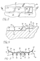
- FIG. 3 is a partially cut-away, top view of one of the plurality of ends including a stepped region formed thereat;
- FIG. 4 is a cut-away, cross-sectional, side view of the stepped region of one of the plurality of ends taken along lines 4 - 4 in FIG. 3;
- FIG. 5 is a cut away, perspective view of a fastener of one embodiment of the invention showing a mold surface and a plurality of trim cover attachment members extending therefrom;
- FIG. 6 is a cut away, perspective view of a foam surface of the fastener of one embodiment of the invention.
- FIG. 7 is a cross-sectional view of the fastener of one embodiment of the invention taken along lines 7 - 7 in FIG. 6;
- FIG. 8 is a cross sectional, side view, partially cut away, of the stepped region of one of the ends of the mold trench shown in FIG. 4 with the fastener of one embodiment of the invention placed thereon;
- FIG. 9 is a partially exploded view of a seat cushion assembly including a foam pad having the fastener of one embodiment of the invention secured within a channel thereof, and a trim cover to be secured to the foam pad.
- a tooling member generally indicated at 10
- the mold 14 includes a lower mold 16 and an upper mold 18 .
- the lower mold 16 is fixed to the platen 12 while the upper mold 18 is movable relative to the lower mold 16 .
- the upper mold 18 moves between a closed position in which various moldable materials, such as foam, may be injected into a mold cavity 20 and an open position (shown in FIG. 1) in which the upper mold 18 is moved away from the lower mold 16 allowing a resulting foam pad to be removed therefrom.
- the lower mold 16 and the upper mold 18 together define the mold cavity 20 for receiving such moldable materials.
- the lower mold 16 includes a bottom mold surface 22 , which delineates the bottom of the mold cavity 20 .
- the bottom mold surface 22 defines mold trenches 24 extending between a plurality of ends 26 . It is contemplated that any number of mold trenches 24 may be formed within the bottom mold surface 22 . And although each mold trench 24 is shown having two ends 26 , it is also contemplated that each mold trench 24 could have more than two ends 26 . For example, the mold trench 24 may be T-shaped having three ends 26 .
- each one of the plurality of ends 26 of the mold trench 24 includes a stepped region, generally indicated at 28 .
- a mold trench floor 30 extends between the stepped regions 28 at each of the plurality of ends 26 of the mold trench 24 .
- the stepped region 28 includes a step, generally shown at 32 , having a raised horizontal surface 34 and a vertical surface 36 extending between the raised horizontal surface 34 and the mold trench floor 30 .
- the step 32 has a step depth D 1 defined as the distance between the horizontal surface 34 of the step 32 and the bottom mold surface 22 of the lower mold 16 disposed adjacent the mold trench 24 .
- the mold trench 24 meanwhile, has a trench depth D 2 defined as the distance between the mold trench floor 30 and the bottom mold surface 22 of the lower mold 16 disposed adjacent the mold trench 24 .
- the depth D 1 of the step 32 is less than the depth D 2 of the mold trench 24 .
- the mold trench floor 30 includes a strip 38 of ferromagnetic material extending between each of the stepped regions 28 for retaining a fastener within the mold trench 24 , as will be described in detail below.
- the strip 38 is bonded to the mold trench floor 30 with adhesive.
- the strip 38 creates a magnetic field to which a fastener, generally indicated at 42 , is susceptible. Therefore, the strip 38 helps to retain the fastener 42 within the mold trench 24 .
- the mold trench floor 30 may be configured to accommodate placement of the strip 38 therein.
- An end magnet 40 is placed upon the horizontal surface 34 of the step 32 in each stepped region 28 .
- the end magnet 40 is bonded to the horizontal surface 34 with adhesive.
- the end magnet 40 retains the fastener 42 against the horizontal surface 34 of the step 32 by creating a magnetic field to which the fastener 42 is susceptible. This magnetism assists in holding the base ends 50 of the fastener 42 to the horizontal surface 34 of the step 32 .
- the fastener 42 includes a base 44 having a mold surface 46 and a foam surface 48 opposite the mold surface 46 .
- the mold 46 and foam 48 surfaces extend along all of the base 44 .
- the mold 46 and foam 48 surfaces are generally parallel to each other.
- the mold 46 and the foam 48 surfaces are flat.
- the fastener 42 is positioned within the mold trench 24 during molding so that the mold surface 46 thereof is facing the mold trench floor 30 .
- the base 44 extends between a plurality of base ends 50 and longitudinal sides 52 .
- a plurality of sealing arms 54 extends along the length of each of the plurality of longitudinal sides 52 .
- Each of the plurality of sealing arms 54 extends out from the base 44 at an angle thereto and includes a flange 55 extending out from the sealing arms 54 generally perpendicular thereto. The flanges 55 directly engage the mold trench 24 .
- Each of the plurality of sealing arms 54 engages the mold trench 24 to secure the fastener 42 within the mold trench 24 and to seal the mold trench 24 during the molding process. As the foam is placed into the lower mold 16 , the engagement of the plurality of sealing arms 54 with the mold trench 24 prevents any foam from seeping around the foam surface 48 of the fastener 42 and onto the mold surface 46 .
- the mold surface 46 of the fastener 42 includes a plurality of trim cover attachment members 56 extending outwardly therefrom.
- the plurality of trim cover attachment members 56 may be in the form of hooks or loops depending on the form of a plurality of complementary receiving members 72 extending from a trim cover 70 (shown in FIG. 9).
- the plurality of trim cover attachment members 56 secure the trim cover 70 to a foam pad or seat cushion 64 by engaging the plurality of complementary receiving members 72 of the trim cover 70 . This engagement allows the trim cover 70 to remain secured to the foam pad 64 during normal wear-and-tear of a motor vehicle seat (not shown).
- the fastener 42 also includes a plurality of guide members 57 .
- the plurality of guide members 57 is a single row of spike-like projections that extend out from the mold surface 46 .
- the plurality of guide members 57 has squared-off distal ends 59 and are of the same general dimension as the plurality of trim cover attachment members 56 .
- the fastener 42 also includes a plurality of sealing flats 58 .
- Each of the plurality of sealing flats 58 is fixedly secured to each of the plurality of base ends 50 .
- Each of the plurality of sealing flats 58 has a flat surface.
- the sealing flats 58 do not have trim cover attachment members 56 thereon.
- the mold surface 46 is exposed along the sealing flats 58 .
- Each of the plurality of sealing flats 58 completely engages all of the stepped region 28 of the mold trench 24 when the fastener 42 is positioned within the mold trench 24 .
- Each fastener 42 may be of varying length so long as each of the plurality of sealing flats 58 rests on the stepped region 28 of the mold trench 24 .
- a resin bead 60 extends between the plurality of base ends 50 and sealing flats 58 along the foam surface 48 parallel to the plurality of longitudinal sides 52 .
- the resin bead 60 is formed from a ferromagnetic material.
- the resin bead 60 is magnetically susceptible to the magnetic fields created by the magnetic strip 38 extending along the mold trench floor 30 and to the end magnets 40 on the steps 32 of the stepped regions 28 .
- the resin bead 60 is pulled toward the magnetic strip 38 and the end magnet 40 .
- the magnetic susceptibility, along with the abutting engagement each of the plurality of sealing arms 52 has with the mold trench 24 , holds the fastener 42 in place as the foam pad 64 is molded and cured.
- the resin bead 60 does not directly face both the strip 38 and the end magnet 40 (since the resin bead 60 is on the foam surface 48 and it is the mold surface 46 that faces the strip 38 and the end magnet 40 ), the magnetic forces of the strip 38 and the end magnets 40 are sufficient to affect the resin bead 60 to assist holding the fastener 42 within the mold trench 24 .
- a plurality of anchors 62 extends upwardly from each of the plurality of sealing arms 54 .
- each of the plurality of anchors 62 complements each of the rounded ends 55 of the sealing arms 54 .
- Each of the plurality of anchors 62 extends continuously along the length of each of the plurality of sealing arms 54 .
- the plurality of anchors 62 may be of any appropriate shape so long as the plurality of anchors 62 assists in anchoring the fastener 42 within the foam pad 64 , as described below.
- the fastener 42 is positioned within the mold trench 24 so that the mold surface 46 of the fastener 42 is facing the mold trench floor 30 , and each of the plurality of sealing flats 58 of the fastener 42 is laid over the horizontal surface 34 of the step 32 in the stepped region 28 .
- the magnetic strip 38 and the end magnet 40 create a magnetic field that attracts the resin bead 60 , thus retaining the fastener 42 within the mold trench 24 and allowing the plurality of sealing flats 58 to be held on the horizontal surface 34 of the step 32 .
- the sealing arms 54 of the plurality of longitudinal sides 52 engages the mold trench 24 to seal the mold trench 24 so that foam does not seep through the space between the plurality of longitudinal sides 52 and the mold trench 24 .
- the fastener 42 is also securely held within the mold trench 24 by the fastener 42 being pre-cut to a length at which each of the plurality of base ends 50 of the fastener 42 abuts each of the plurality of ends 26 of the mold trench 24 .
- the upper mold 14 With the fastener 42 secured within the mold trench 24 , the upper mold 14 is closed down upon the lower mold 16 and the mold cavity 20 is filled with foam. Because each of the plurality of sealing flats 58 is tightly held against the stepped region 28 , there is no space between the fastener 42 and the mold trench 24 for foam to seep therepast.
- the foam is cured and the foam pad 64 , as shown in FIG. 9, is formed with the fastener 42 bonded thereto.
- the foam forms around each of the plurality of anchors 62 , thus anchoring the fastener 42 within the foam pad 64 .
- the foam pad 64 in the Figures has a seating surface 65 upon which a motor vehicle occupant will sit and a support surface 67 opposite to the seating surface 65 . It should be appreciated by those skilled in the art that the foam pad 64 may be something other than a seat cushion.
- a cushion assembly 66 includes the foam pad 64 , a plurality of channels 68 , and the fastener 42 secured within each of the plurality of channels 68 .
- a fastener 42 is positioned within each of the plurality of channels 68 so that each of the plurality of trim cover attachment members 56 extends outwardly therefrom.
- the foam pad 64 is then covered by the trim cover 70 .
- the trim cover 70 includes the plurality of complementary receiving members 72 extending therefrom and aligned thereon so as to engage the plurality of trim cover attachment members 56 of the fastener 42 as the trim cover 70 is secured to the foam pad 64 .
- the fastener 42 is applied within the mold trench 24 of the mold 14 so that each of the plurality of sealing flats 58 rests upon the stepped region 28 of each of the plurality of ends 26 .
- the mold 14 is filled with foam. As the foam fills the mold 14 it contacts the foam surface 48 of the fastener 42 . But because of the tight seal formed between each of the plurality of sealing flats 58 and the stepped region 28 of the mold trench 24 , the foam does not seep through to the mold surface 46 of the fastener 42 .
- the foam is then cured to form the foam pad 64 with the fastener 42 bonded thereto.
- the foam pad 64 may then be covered with the trim cover 70 .
Abstract
A fastener secures a trim cover to a foam pad. The fastener is positionable within a mold trench, which extends between a plurality of ends having stepped regions. The fastener includes a base having a mold surface and a foam surface opposite to the mold surface. The base extends between a plurality of base ends and longitudinal sides. The fastener also includes a plurality of trim cover attachment members extending outwardly from the mold surface for securing the trim cover thereto. In addition, the fastener includes a plurality of sealing flats that sealingly engage each of the stepped regions to prevent foam from flowing past the stepped regions and onto the plurality of trim cover attachment members on the mold surface.
Description
- 1. Field of the Invention
- This invention relates to a fastener for securing a trim cover to a foam pad. In particular, this invention relates to a trim cover fastener that is bonded to the foam pad during the molding of the foam pad.
- 2. Description of Related Art
- Many surfaces within a passenger compartment of a motor vehicle require padding for comfort reasons. Aesthetically, materials used to pad surfaces lack the desired finish. Therefore, trim covers are employed to cover the padding so the look and feel of the padded surfaces is aligned with expectations of those occupying the passenger compartment.
- Manufacturing methods typically utilize foam and mold processes to create the padding used for interior trim components and seat assemblies. Once the foam has been molded to a desired shape, it must be covered. These methods are labor intensive.
- One method for securing a trim cover to a piece of molded foam, e.g., a seat cushion, is to mold fasteners into the foam cushion as it is molded and cured. In this securing method, a fastener extends along a portion of the foam cushion surface. The fastener has a plurality of trim cover attachment members extending out therefrom to receive and secure the trim cover to the foam cushion. An example of this type of fastener is disclosed in U.S. Pat. No. 5,900,303. In this patent, the trim cover attachment members extend out from a fastener body across the entire length thereof.
- A problem associated with this type of manufactured foam cushion arises because it is difficult to mold the fasteners and the foam together without having the foam flow around the fastener body eliminating the ability of the fastener to secure a trim cover thereto. The above-mentioned reference attempts to overcome this problem by sealing the ends of the fasteners with a sealant. This solution is not desirable because it does not completely prevented intrusion of foam around the fasteners. This is because the ends of the fastener are not securely positioned within the mold. Thus, foam may seep through small spaces between the ends of the fasteners and the mold. As a result, the trim cover attachment members on the fastener assemblies are partially covered with foam and the attachment of the trim cover to the foam pad is weakened.
- If it is determined that too much foam has covered the fastener, further treatment of the fastener assembly is required to remove the foam. This cleaning process introduces irregularities in the manufacturing process, additional costs, and increased cycle times.
- A fastener secures a trim cover to a foam pad. The fastener is positionable within a mold trench of a mold for receiving foam. The fastener includes a base having a mold surface and a foam surface opposite thereto. The base extends between a plurality of base ends and longitudinal sides. The fastener also includes a plurality of trim cover attachment members extending outwardly from the mold surface for securing the trim cover thereto. In addition, the fastener includes a plurality of sealing flats sealingly engaging each of the stepped regions to prevent foam from flowing therepast. Each of the plurality of sealing flats is fixedly secured to each of the plurality of base ends.
- Advantages of the invention will be readily appreciated as the same becomes better understood by reference to the following detailed description when considered in connection with the accompanying drawings wherein:
- FIG. 1 is a perspective view of a tooling member including a platen supporting a mold;
- FIG. 2 is a top view of a lower mold of the mold defining a mold trench having a plurality of ends;
- FIG. 3 is a partially cut-away, top view of one of the plurality of ends including a stepped region formed thereat;
- FIG. 4 is a cut-away, cross-sectional, side view of the stepped region of one of the plurality of ends taken along lines 4-4 in FIG. 3;
- FIG. 5 is a cut away, perspective view of a fastener of one embodiment of the invention showing a mold surface and a plurality of trim cover attachment members extending therefrom;
- FIG. 6 is a cut away, perspective view of a foam surface of the fastener of one embodiment of the invention;
- FIG. 7 is a cross-sectional view of the fastener of one embodiment of the invention taken along lines 7-7 in FIG. 6;
- FIG. 8 is a cross sectional, side view, partially cut away, of the stepped region of one of the ends of the mold trench shown in FIG. 4 with the fastener of one embodiment of the invention placed thereon; and
- FIG. 9 is a partially exploded view of a seat cushion assembly including a foam pad having the fastener of one embodiment of the invention secured within a channel thereof, and a trim cover to be secured to the foam pad.
- Referring to FIG. 1, a tooling member, generally indicated at 10, includes a
platen 12 supporting a mold, generally shown at 14. The mold 14 includes alower mold 16 and anupper mold 18. Thelower mold 16 is fixed to theplaten 12 while theupper mold 18 is movable relative to thelower mold 16. Theupper mold 18 moves between a closed position in which various moldable materials, such as foam, may be injected into amold cavity 20 and an open position (shown in FIG. 1) in which theupper mold 18 is moved away from thelower mold 16 allowing a resulting foam pad to be removed therefrom. In the closed position, thelower mold 16 and theupper mold 18 together define themold cavity 20 for receiving such moldable materials. - Referring to FIG. 2, the
lower mold 16 includes abottom mold surface 22, which delineates the bottom of themold cavity 20. Thebottom mold surface 22 definesmold trenches 24 extending between a plurality ofends 26. It is contemplated that any number ofmold trenches 24 may be formed within thebottom mold surface 22. And although eachmold trench 24 is shown having twoends 26, it is also contemplated that eachmold trench 24 could have more than twoends 26. For example, themold trench 24 may be T-shaped having threeends 26. - Referring to FIGS. 3 and 4, each one of the plurality of
ends 26 of themold trench 24 includes a stepped region, generally indicated at 28. Amold trench floor 30 extends between thestepped regions 28 at each of the plurality ofends 26 of themold trench 24. Thestepped region 28 includes a step, generally shown at 32, having a raisedhorizontal surface 34 and avertical surface 36 extending between the raisedhorizontal surface 34 and themold trench floor 30. Thestep 32 has a step depth D1 defined as the distance between thehorizontal surface 34 of thestep 32 and thebottom mold surface 22 of thelower mold 16 disposed adjacent themold trench 24. Themold trench 24, meanwhile, has a trench depth D2 defined as the distance between themold trench floor 30 and thebottom mold surface 22 of thelower mold 16 disposed adjacent themold trench 24. The depth D1 of thestep 32 is less than the depth D2 of themold trench 24. - The
mold trench floor 30 includes astrip 38 of ferromagnetic material extending between each of thestepped regions 28 for retaining a fastener within themold trench 24, as will be described in detail below. Thestrip 38 is bonded to themold trench floor 30 with adhesive. Thestrip 38 creates a magnetic field to which a fastener, generally indicated at 42, is susceptible. Therefore, thestrip 38 helps to retain thefastener 42 within themold trench 24. Themold trench floor 30 may be configured to accommodate placement of thestrip 38 therein. - An
end magnet 40 is placed upon thehorizontal surface 34 of thestep 32 in each steppedregion 28. Theend magnet 40 is bonded to thehorizontal surface 34 with adhesive. Theend magnet 40 retains thefastener 42 against thehorizontal surface 34 of thestep 32 by creating a magnetic field to which thefastener 42 is susceptible. This magnetism assists in holding the base ends 50 of thefastener 42 to thehorizontal surface 34 of thestep 32. - Referring to FIGS. 5 and 6, the
fastener 42 includes a base 44 having amold surface 46 and a foam surface 48 opposite themold surface 46. Themold 46 and foam 48 surfaces extend along all of thebase 44. Themold 46 and foam 48 surfaces are generally parallel to each other. Themold 46 and the foam 48 surfaces are flat. - The
fastener 42 is positioned within themold trench 24 during molding so that themold surface 46 thereof is facing themold trench floor 30. Thebase 44 extends between a plurality of base ends 50 andlongitudinal sides 52. - A plurality of sealing
arms 54 extends along the length of each of the plurality oflongitudinal sides 52. Each of the plurality of sealingarms 54 extends out from the base 44 at an angle thereto and includes aflange 55 extending out from the sealingarms 54 generally perpendicular thereto. Theflanges 55 directly engage themold trench 24. Each of the plurality of sealingarms 54 engages themold trench 24 to secure thefastener 42 within themold trench 24 and to seal themold trench 24 during the molding process. As the foam is placed into thelower mold 16, the engagement of the plurality of sealingarms 54 with themold trench 24 prevents any foam from seeping around the foam surface 48 of thefastener 42 and onto themold surface 46. - The
mold surface 46 of thefastener 42 includes a plurality of trimcover attachment members 56 extending outwardly therefrom. The plurality of trimcover attachment members 56 may be in the form of hooks or loops depending on the form of a plurality ofcomplementary receiving members 72 extending from a trim cover 70 (shown in FIG. 9). The plurality of trimcover attachment members 56 secure thetrim cover 70 to a foam pad orseat cushion 64 by engaging the plurality ofcomplementary receiving members 72 of thetrim cover 70. This engagement allows thetrim cover 70 to remain secured to thefoam pad 64 during normal wear-and-tear of a motor vehicle seat (not shown). - The
fastener 42 also includes a plurality ofguide members 57. The plurality ofguide members 57 is a single row of spike-like projections that extend out from themold surface 46. There is a single line of the plurality ofguide members 57 extending along each of the plurality oflongitudinal sides 52. The plurality ofguide members 57 has squared-off distal ends 59 and are of the same general dimension as the plurality of trimcover attachment members 56. - The
fastener 42 also includes a plurality of sealingflats 58. Each of the plurality of sealingflats 58 is fixedly secured to each of the plurality of base ends 50. Each of the plurality of sealingflats 58 has a flat surface. The sealingflats 58 do not have trimcover attachment members 56 thereon. Thus, themold surface 46 is exposed along the sealingflats 58. Each of the plurality of sealingflats 58 completely engages all of the steppedregion 28 of themold trench 24 when thefastener 42 is positioned within themold trench 24. Eachfastener 42 may be of varying length so long as each of the plurality of sealingflats 58 rests on the steppedregion 28 of themold trench 24. - A
resin bead 60 extends between the plurality of base ends 50 and sealingflats 58 along the foam surface 48 parallel to the plurality oflongitudinal sides 52. Theresin bead 60 is formed from a ferromagnetic material. Theresin bead 60 is magnetically susceptible to the magnetic fields created by themagnetic strip 38 extending along themold trench floor 30 and to theend magnets 40 on thesteps 32 of the steppedregions 28. Upon positioning of thefastener 42, theresin bead 60 is pulled toward themagnetic strip 38 and theend magnet 40. The magnetic susceptibility, along with the abutting engagement each of the plurality of sealingarms 52 has with themold trench 24, holds thefastener 42 in place as thefoam pad 64 is molded and cured. - Even though the
resin bead 60 does not directly face both thestrip 38 and the end magnet 40 (since theresin bead 60 is on the foam surface 48 and it is themold surface 46 that faces thestrip 38 and the end magnet 40), the magnetic forces of thestrip 38 and theend magnets 40 are sufficient to affect theresin bead 60 to assist holding thefastener 42 within themold trench 24. - Referring to FIG. 7, a plurality of
anchors 62 extends upwardly from each of the plurality of sealingarms 54. In the embodiment shown, each of the plurality ofanchors 62 complements each of the rounded ends 55 of the sealingarms 54. Each of the plurality ofanchors 62 extends continuously along the length of each of the plurality of sealingarms 54. The plurality ofanchors 62 may be of any appropriate shape so long as the plurality ofanchors 62 assists in anchoring thefastener 42 within thefoam pad 64, as described below. - In operation, the
fastener 42 is positioned within themold trench 24 so that themold surface 46 of thefastener 42 is facing themold trench floor 30, and each of the plurality of sealingflats 58 of thefastener 42 is laid over thehorizontal surface 34 of thestep 32 in the steppedregion 28. Themagnetic strip 38 and theend magnet 40 create a magnetic field that attracts theresin bead 60, thus retaining thefastener 42 within themold trench 24 and allowing the plurality of sealingflats 58 to be held on thehorizontal surface 34 of thestep 32. In addition, the sealingarms 54 of the plurality oflongitudinal sides 52 engages themold trench 24 to seal themold trench 24 so that foam does not seep through the space between the plurality oflongitudinal sides 52 and themold trench 24. Thefastener 42 is also securely held within themold trench 24 by thefastener 42 being pre-cut to a length at which each of the plurality of base ends 50 of thefastener 42 abuts each of the plurality ofends 26 of themold trench 24. - With the
fastener 42 secured within themold trench 24, the upper mold 14 is closed down upon thelower mold 16 and themold cavity 20 is filled with foam. Because each of the plurality of sealingflats 58 is tightly held against the steppedregion 28, there is no space between thefastener 42 and themold trench 24 for foam to seep therepast. The foam is cured and thefoam pad 64, as shown in FIG. 9, is formed with thefastener 42 bonded thereto. During the molding process, the foam forms around each of the plurality ofanchors 62, thus anchoring thefastener 42 within thefoam pad 64. Thefoam pad 64 in the Figures has aseating surface 65 upon which a motor vehicle occupant will sit and asupport surface 67 opposite to theseating surface 65. It should be appreciated by those skilled in the art that thefoam pad 64 may be something other than a seat cushion. - A
cushion assembly 66 includes thefoam pad 64, a plurality of channels 68, and thefastener 42 secured within each of the plurality of channels 68. Afastener 42 is positioned within each of the plurality of channels 68 so that each of the plurality of trimcover attachment members 56 extends outwardly therefrom. Thefoam pad 64 is then covered by thetrim cover 70. Thetrim cover 70 includes the plurality ofcomplementary receiving members 72 extending therefrom and aligned thereon so as to engage the plurality of trimcover attachment members 56 of thefastener 42 as thetrim cover 70 is secured to thefoam pad 64. - In a method for forming the
seat cushion assembly 66, thefastener 42 is applied within themold trench 24 of the mold 14 so that each of the plurality of sealingflats 58 rests upon the steppedregion 28 of each of the plurality of ends 26. Next, the mold 14 is filled with foam. As the foam fills the mold 14 it contacts the foam surface 48 of thefastener 42. But because of the tight seal formed between each of the plurality of sealingflats 58 and the steppedregion 28 of themold trench 24, the foam does not seep through to themold surface 46 of thefastener 42. The foam is then cured to form thefoam pad 64 with thefastener 42 bonded thereto. Thefoam pad 64 may then be covered with thetrim cover 70. - The invention has been described in an illustrative manner. It is to be understood that the terminology, which has been used, is intended to be in the nature of words of description rather than of limitation.
- Many modifications and variations of the invention are possible in light of the above teachings. Therefore, within the scope of the appended claims, the invention may be practiced other than as specifically described.
Claims (24)
1. A fastener for securing a trim cover to a foam pad, said fastener positionable within a mold trench of a mold for receiving foam, the mold trench defining a trench depth and extending between a plurality of ends having stepped regions defining a step depth more shallow than the trench depth, said fastener comprising:
a base having a mold surface and a foam surface opposite thereto, said base extending between a plurality of base ends and longitudinal sides;
a plurality of trim cover attachment members extending outwardly from said mold surface for securing the trim cover thereto; and
a plurality of sealing flats sealingly engaging each of the stepped regions to prevent foam from flowing therepast, each of said plurality of sealing flats fixedly secured to each of said plurality of base ends.
2. A fastener as set forth in claim 1 including a plurality of sealing arms defining a length and extending along each of said plurality of longitudinal sides, said plurality of sealing arms engaging the mold trench to secure said fastener within the mold trench and to seal the mold trench from the foam.
3. A fastener as set forth in claim 2 wherein each of said plurality of sealing arms extends along each of said plurality of sealing flats.
4. A fastener as set forth in claim 3 including a plurality of anchors fixedly secured to each of said plurality of sealing arms and extending out therefrom, said plurality of anchors securing said fastener to the foam pad.
5. A fastener as set forth in claim 4 wherein each of said plurality of anchors extends continuously along each of said plurality of sealing arms over said length thereof.
6. A fastener as set forth in claim 5 wherein each of said plurality of anchors extends along each of said plurality of sealing flats.
7. A fastener as set forth in claim 6 wherein each of said plurality of sealing flats is magnetized.
8. A fastener as set forth in claim 7 wherein each of said plurality of sealing flats includes a magnetic flat that is magnetically susceptible.
9. A fastener as set forth in claim 8 including a resin bead secured to said foam surface and extending along said plurality of longitudinal sides.
10. A fastener as set forth in claim 9 wherein said plurality of trim cover attachment members includes hooks.
11. A fastener as set forth in claim 9 wherein said plurality of trim cover attachment members includes loops.
12. A seat cushion assembly for a motor vehicle, said seat cushion assembly comprising:
a foam pad having a seating surface and a support surface;
a channel formed within said seating surface of said foam pad; and
a fastener bonded to said foam pad within said channel, said fastener including a base having a mold surface extending away from said foam pad and a foam surface opposite thereto, said base extending between longitudinal sides and a plurality of ends, said fastener including a plurality of sealing flats each fixedly secured to each of said plurality of ends.
13. A seat cushion assembly as set forth in claim 12 wherein said fastener includes sealing arms extending along each of said longitudinal sides.
14. A seat cushion assembly as set forth in claim 13 including a trim cover for covering said foam pad.
15. A seat cushion assembly as set forth in claim 14 wherein said fastener includes a plurality of trim cover attachment members extending out therefrom for securing said trim cover to said foam pad.
16. A seat cushion assembly as set forth in claim 15 wherein each of said plurality of sealing arms extends along each of said plurality of sealing flats.
17. A seat cushion assembly as set forth in claim 16 including a plurality of anchors fixedly secured to each of said sealing arms and extending out therefrom, said plurality of anchors securing said fastener to said foam pad.
18. A seat cushion assembly as set forth in claim 17 wherein each of said plurality of anchors extends continuously along each of said sealing arms over said length thereof.
19. A seat cushion assembly as set forth in claim 18 wherein each of said plurality of anchors extends along each of said plurality of sealing flats.
20. A seat cushion assembly as set forth in claim 19 wherein said plurality of trim cover attachment members includes hooks.
21. A seat cushion assembly as set forth in claim 20 wherein said plurality of trim cover attachment members includes loops.
22. A method for forming a seat cushion assembly using a trim cover, foam, a foam pad, a mold having a mold trench extending between a plurality of ends having stepped regions, a fastener having a base extending between longitudinal sides and base ends, and defining a mold surface and a foam surface, a plurality of trim cover attachment members, and sealing flats formed at the base ends, the method comprising the steps of:
applying the fastener within the mold trench so that each of the sealing flats rests upon each of the stepped regions;
filling the mold with the foam; and
curing the foam to form the foam pad with the fastener bonded thereto.
23. A method as set forth in claim 22 including the step of covering the foam pad using the trim cover.
24. A method as set forth in claim 23 including the step of securing the trim cover to the foam pad by engaging the trim cover with the plurality of trim cover attachment members.
Priority Applications (2)
| Application Number | Priority Date | Filing Date | Title |
|---|---|---|---|
| US10/125,945 US6842950B2 (en) | 2002-04-19 | 2002-04-19 | Shieldless hook and loop fastener |
| CA2423939A CA2423939C (en) | 2002-04-19 | 2003-03-28 | Shieldless hook and loop fastener |
Applications Claiming Priority (1)
| Application Number | Priority Date | Filing Date | Title |
|---|---|---|---|
| US10/125,945 US6842950B2 (en) | 2002-04-19 | 2002-04-19 | Shieldless hook and loop fastener |
Publications (2)
| Publication Number | Publication Date |
|---|---|
| US20030197414A1 true US20030197414A1 (en) | 2003-10-23 |
| US6842950B2 US6842950B2 (en) | 2005-01-18 |
Family
ID=29214885
Family Applications (1)
| Application Number | Title | Priority Date | Filing Date |
|---|---|---|---|
| US10/125,945 Expired - Fee Related US6842950B2 (en) | 2002-04-19 | 2002-04-19 | Shieldless hook and loop fastener |
Country Status (2)
| Country | Link |
|---|---|
| US (1) | US6842950B2 (en) |
| CA (1) | CA2423939C (en) |
Cited By (3)
| Publication number | Priority date | Publication date | Assignee | Title |
|---|---|---|---|---|
| WO2009151233A2 (en) * | 2008-06-13 | 2009-12-17 | 주식회사 시디즈 | Seat board |
| EP2208596A3 (en) * | 2009-01-14 | 2011-03-23 | YKK Corporation | Systems and methods of installing hook fastener elements in a mold assembly |
| US20120001464A1 (en) * | 2009-03-18 | 2012-01-05 | Hwa Cheng Teoh | Vehicle seat cover |
Families Citing this family (10)
| Publication number | Priority date | Publication date | Assignee | Title |
|---|---|---|---|---|
| FR2846274B1 (en) * | 2002-10-23 | 2004-12-17 | Aplix Sa | OVERLAPS WITH SMALL BELT WITH HOOKS |
| WO2005077219A1 (en) * | 2004-02-10 | 2005-08-25 | Avery Dennison Corporation | Fastening member for a molded article |
| US7430793B2 (en) * | 2005-07-25 | 2008-10-07 | Lear Corporation | Apparatus for securing a trim cover with a foam pad and method of using the same |
| US7954208B2 (en) * | 2007-10-31 | 2011-06-07 | Avery Dennison Corporation | Fastening member for a molded article |
| US20090276986A1 (en) * | 2008-05-12 | 2009-11-12 | Velcro Industries B.V. | Touch fastener products |
| FR2934195B1 (en) * | 2008-07-24 | 2011-04-01 | Faurecia Sieges Automobile | TRIM FORMING FOR MOTOR VEHICLE SEATS |
| FR3009224B1 (en) | 2013-08-02 | 2016-01-01 | Faurecia Sieges Automobile | METHOD OF FORMING TRIM FOR AUTOMOTIVE SEAT |
| FR3009222B1 (en) | 2013-08-02 | 2016-01-01 | Faurecia Sieges Automobile | FORMING A TRIM FOR A MOTOR VEHICLE SEAT |
| FR3035038B1 (en) | 2015-04-16 | 2017-05-12 | Faurecia Sieges D'automobile | ALIGNMENT OF COIFFE PARTS FOR SEATS OF MOTOR VEHICLES |
| US10316695B2 (en) | 2015-12-10 | 2019-06-11 | General Electric Company | Metallic attachment system integrated into a composite structure |
Citations (14)
| Publication number | Priority date | Publication date | Assignee | Title |
|---|---|---|---|---|
| US4842916A (en) * | 1987-01-19 | 1989-06-27 | Kuraray Company Ltd. | Separable fastener component & moldings attached with such fastener component |
| US4881997A (en) * | 1985-07-17 | 1989-11-21 | Velcro Industries. B.V. | Method for adapting separable fasteners for attachment to other objects |
| US5171395A (en) * | 1990-08-09 | 1992-12-15 | Velcro Industries B.V. | Shaped mold-in |
| US5180618A (en) * | 1990-01-25 | 1993-01-19 | Velcro Industries B.V. | Separable fasteners for attachment to other objects |
| US5422156A (en) * | 1993-04-23 | 1995-06-06 | Aplix, Inc. | Fastening member with ferromagnetic attachment strip |
| US5500268A (en) * | 1995-01-31 | 1996-03-19 | Aplix, Inc. | Fastener assembly with magnetic side and end seals and method |
| US5606781A (en) * | 1995-02-17 | 1997-03-04 | Velcro Industries, B.V. | Separable fastener having a bald perimeter rib bounded by fastening elements |
| US5688576A (en) * | 1993-11-29 | 1997-11-18 | Kuraray Co., Ltd. | Fastener member for molding and production of plastic molded article with fastener member molded thereon |
| US5766723A (en) * | 1996-11-12 | 1998-06-16 | Woodbridge Foam Corporation | Fastener assembly with peripheral seal |
| US5786061A (en) * | 1991-05-03 | 1998-07-28 | Velcro Industries B.V. | Separable fastener having a perimeter cover gasket |
| US5900303A (en) * | 1997-09-30 | 1999-05-04 | Aplix, Inc. | Fastener assembly with mechanical end seals |
| US6439537B1 (en) * | 2000-09-18 | 2002-08-27 | Ykk Corporation Of America | Forming mold with recess having snap-fit end seal |
| US6537643B1 (en) * | 2000-08-16 | 2003-03-25 | Gottlieb Binder Gmbh & Co. | Adhering closure element |
| US6596371B1 (en) * | 2000-01-19 | 2003-07-22 | Aplix, Inc. | Component for overcasting for a moulded object |
-
2002
- 2002-04-19 US US10/125,945 patent/US6842950B2/en not_active Expired - Fee Related
-
2003
- 2003-03-28 CA CA2423939A patent/CA2423939C/en not_active Expired - Fee Related
Patent Citations (14)
| Publication number | Priority date | Publication date | Assignee | Title |
|---|---|---|---|---|
| US4881997A (en) * | 1985-07-17 | 1989-11-21 | Velcro Industries. B.V. | Method for adapting separable fasteners for attachment to other objects |
| US4842916A (en) * | 1987-01-19 | 1989-06-27 | Kuraray Company Ltd. | Separable fastener component & moldings attached with such fastener component |
| US5180618A (en) * | 1990-01-25 | 1993-01-19 | Velcro Industries B.V. | Separable fasteners for attachment to other objects |
| US5171395A (en) * | 1990-08-09 | 1992-12-15 | Velcro Industries B.V. | Shaped mold-in |
| US5786061A (en) * | 1991-05-03 | 1998-07-28 | Velcro Industries B.V. | Separable fastener having a perimeter cover gasket |
| US5422156A (en) * | 1993-04-23 | 1995-06-06 | Aplix, Inc. | Fastening member with ferromagnetic attachment strip |
| US5688576A (en) * | 1993-11-29 | 1997-11-18 | Kuraray Co., Ltd. | Fastener member for molding and production of plastic molded article with fastener member molded thereon |
| US5500268A (en) * | 1995-01-31 | 1996-03-19 | Aplix, Inc. | Fastener assembly with magnetic side and end seals and method |
| US5606781A (en) * | 1995-02-17 | 1997-03-04 | Velcro Industries, B.V. | Separable fastener having a bald perimeter rib bounded by fastening elements |
| US5766723A (en) * | 1996-11-12 | 1998-06-16 | Woodbridge Foam Corporation | Fastener assembly with peripheral seal |
| US5900303A (en) * | 1997-09-30 | 1999-05-04 | Aplix, Inc. | Fastener assembly with mechanical end seals |
| US6596371B1 (en) * | 2000-01-19 | 2003-07-22 | Aplix, Inc. | Component for overcasting for a moulded object |
| US6537643B1 (en) * | 2000-08-16 | 2003-03-25 | Gottlieb Binder Gmbh & Co. | Adhering closure element |
| US6439537B1 (en) * | 2000-09-18 | 2002-08-27 | Ykk Corporation Of America | Forming mold with recess having snap-fit end seal |
Cited By (6)
| Publication number | Priority date | Publication date | Assignee | Title |
|---|---|---|---|---|
| WO2009151233A2 (en) * | 2008-06-13 | 2009-12-17 | 주식회사 시디즈 | Seat board |
| WO2009151233A3 (en) * | 2008-06-13 | 2010-03-11 | 주식회사 시디즈 | Seat board |
| EP2208596A3 (en) * | 2009-01-14 | 2011-03-23 | YKK Corporation | Systems and methods of installing hook fastener elements in a mold assembly |
| US8043541B2 (en) | 2009-01-14 | 2011-10-25 | Ykk Corporation | Systems and methods of installing hook fastener elements in a mold assembly |
| CN101822449B (en) * | 2009-01-14 | 2012-07-11 | Ykk株式会社 | Systems and methods of installing hook fastener elements in a mold assembly and foam material |
| US20120001464A1 (en) * | 2009-03-18 | 2012-01-05 | Hwa Cheng Teoh | Vehicle seat cover |
Also Published As
| Publication number | Publication date |
|---|---|
| CA2423939C (en) | 2012-04-10 |
| US6842950B2 (en) | 2005-01-18 |
| CA2423939A1 (en) | 2003-10-19 |
Similar Documents
| Publication | Publication Date | Title |
|---|---|---|
| US6842950B2 (en) | Shieldless hook and loop fastener | |
| US5500268A (en) | Fastener assembly with magnetic side and end seals and method | |
| JP4769245B2 (en) | Hook fastener parts | |
| US5972465A (en) | Fastener member for molding and production of plastic molded article with fastener member molded thereon | |
| KR100685334B1 (en) | Component for overcasting for a moulded object and manufacturing process thereof | |
| CA2419693C (en) | Attachment device | |
| EP0440286B1 (en) | Plastics fastener to attach door trim panel | |
| US20030213105A1 (en) | Extruded flexible self-locking trim cover assembly retention clip and method for using same | |
| JPH11156071A (en) | Fastener assembly | |
| US20030162008A1 (en) | Foam pad and process for production thereof | |
| JPH05261742A (en) | Method for attaching surface fastener clamp to seat cushion material and foaming mold | |
| EP1348530B1 (en) | Fastening member and process for producing molded resin article having the same | |
| US7357443B2 (en) | Deformable component, especially accessory for a vehicle, and process for manufacturing | |
| CZ230295A3 (en) | Packing for motor vehicles and process for producing thereof | |
| US20020031637A1 (en) | Molded cushion element and method for production thereof | |
| US20070028386A1 (en) | Seat cushion with integral cover attachment | |
| KR101327387B1 (en) | A seat pad equipped with the hook of velcro tape and the manufacturing method thereof | |
| US6468371B1 (en) | Method for producing a moulded part, especially a sheet member for a car or plane passenger seat | |
| JPH029610A (en) | Manufacture of head-rest for automobile | |
| JP3264550B2 (en) | Grooved sheet and manufacturing method thereof | |
| JPH08140713A (en) | Detaching member for mold-in molding and production of resin molding by using the same | |
| JPH05211910A (en) | Hook-and-loop fastener engaging piece for seat cushion | |
| JP3621201B2 (en) | Suspended surface fastener integrated foam type | |
| US20230337828A1 (en) | Vehicle seat assembly and method of forming | |
| JP4368473B2 (en) | Locking member for mold-in molding |
Legal Events
| Date | Code | Title | Description |
|---|---|---|---|
| AS | Assignment |
Owner name: INTIER AUTOMOTIVE INC., CANADA Free format text: ASSIGNMENT OF ASSIGNORS INTEREST;ASSIGNORS:FLEUCHAUS, KURT;PEKRUL, HUGH C.;REEL/FRAME:013614/0552;SIGNING DATES FROM 20021114 TO 20021205 |
|
| FPAY | Fee payment |
Year of fee payment: 4 |
|
| REMI | Maintenance fee reminder mailed | ||
| LAPS | Lapse for failure to pay maintenance fees | ||
| STCH | Information on status: patent discontinuation |
Free format text: PATENT EXPIRED DUE TO NONPAYMENT OF MAINTENANCE FEES UNDER 37 CFR 1.362 |
|
| FP | Lapsed due to failure to pay maintenance fee |
Effective date: 20130118 |