US20030197700A1 - Information processing apparatus, program for product assembly process display, and method for product assembly process display - Google Patents
Information processing apparatus, program for product assembly process display, and method for product assembly process display Download PDFInfo
- Publication number
- US20030197700A1 US20030197700A1 US10/327,876 US32787602A US2003197700A1 US 20030197700 A1 US20030197700 A1 US 20030197700A1 US 32787602 A US32787602 A US 32787602A US 2003197700 A1 US2003197700 A1 US 2003197700A1
- Authority
- US
- United States
- Prior art keywords
- data
- parts
- assembly
- output
- image
- Prior art date
- Legal status (The legal status is an assumption and is not a legal conclusion. Google has not performed a legal analysis and makes no representation as to the accuracy of the status listed.)
- Granted
Links
Images


Classifications
-
- G—PHYSICS
- G06—COMPUTING; CALCULATING OR COUNTING
- G06T—IMAGE DATA PROCESSING OR GENERATION, IN GENERAL
- G06T13/00—Animation
-
- G—PHYSICS
- G06—COMPUTING; CALCULATING OR COUNTING
- G06T—IMAGE DATA PROCESSING OR GENERATION, IN GENERAL
- G06T19/00—Manipulating 3D models or images for computer graphics
- G06T19/20—Editing of 3D images, e.g. changing shapes or colours, aligning objects or positioning parts
-
- G—PHYSICS
- G09—EDUCATION; CRYPTOGRAPHY; DISPLAY; ADVERTISING; SEALS
- G09B—EDUCATIONAL OR DEMONSTRATION APPLIANCES; APPLIANCES FOR TEACHING, OR COMMUNICATING WITH, THE BLIND, DEAF OR MUTE; MODELS; PLANETARIA; GLOBES; MAPS; DIAGRAMS
- G09B5/00—Electrically-operated educational appliances
- G09B5/06—Electrically-operated educational appliances with both visual and audible presentation of the material to be studied
-
- G—PHYSICS
- G06—COMPUTING; CALCULATING OR COUNTING
- G06T—IMAGE DATA PROCESSING OR GENERATION, IN GENERAL
- G06T2219/00—Indexing scheme for manipulating 3D models or images for computer graphics
- G06T2219/20—Indexing scheme for editing of 3D models
- G06T2219/2008—Assembling, disassembling
Definitions
- This invention relates to an information processing apparatus, a program for product assembly process display, and a method for product assembly process display, that output scenes on a screen, for assembling a product made from a plurality of parts.
- image used in a 2-D (two-dimensional) CAD is an illustrated view from one direction, therefore it is not necessarily the suitable image for the assembly scene.
- 2-D image may be difficult to easily illustrate the assembly scene.
- it is possible to select an arbitrarily angle when a 3-D (three-dimensional) CAD image is applied in order to easily illustrate the assembly scene, an enormous amount of data needs to be processed for outputting the assembly scene, thereby making it difficult for a PC for a regular office use to output the data, and eventually increasing the cost.
- the present invention addresses the above-described problems of the conventional technologies.
- the main purpose of the invention is to provide an information processing apparatus, a program for product assembly process display, and a method for product assembly process display, that use only a small amount of data handling the output of assembly scenes, output assembly scene with a low processing capability, apply data generated from a designing process, and simply illustrate the assembly scene using image of a part from an angle suitable for the assembly scene display.
- the image processing apparatus is provided with a 3-D data memory that stores 3-D data related to a product assembled by a plurality of parts, a data retriever that retrieves 3-D data for each part from the 3-D data related to the product, a 2-D data generator that generates 2-D data illustrating an image of each part viewed from a predetermined direction based on the 3-D data of each part, a 2-D data memory that stores 2-D data for each part, and a management data generator that generates management data describing steps to allow another information processing apparatus to output an assembly scene on a display, by using the 2-D data of each part. Accordingly, it is possible to lighten the load of assembly scene output, as well as reducing the cost by using a general PC as the information processing apparatus to output the assembly scene.
- FIG. 1 is a schematic block diagram illustrating an information processing apparatus according to the present invention
- FIG. 2 is a schematic block diagram illustrating a PC for assembly scene output of FIG. 1;
- FIG. 3 is a schematic diagram illustrating a display output at the PC for outputting the assembly scene of FIG. 2;
- FIG. 4 is another schematic diagram illustrating a display output at the PC for outputting the assembly scene of FIG. 2;
- FIG. 5 is another schematic diagram illustrating a display output at the PC for outputting the assembly scene of FIG. 2;
- FIG. 6 is another schematic diagram illustrating a display output at the PC for outputting the assembly scene of FIG. 2;
- FIG. 7 illustrates a control status of the display output at the PC for outputting the assembly scene of FIG. 2;
- FIG. 8 illustrates a display screen of a parts tree structure diagram at the information processing apparatus for generating data of FIG. 1;
- FIG. 9 illustrates a display screen of a specified range of an outputting part at the information processing apparatus for generating data of FIG. 1;
- FIG. 10 illustrates another display screen of a parts tree structure diagram at the information processing apparatus for generating data of FIG. 1;
- FIG. 11 illustrates another display screen of a parts tree structure diagram at the information processing apparatus for generating data of FIG. 1;
- FIG. 12 illustrates another display screen of a parts tree structure diagram at the information processing apparatus for generating data of FIG. 1;
- FIG. 13 illustrates a preliminary management table generated by a management table generator of FIG. 1;
- FIG. 14 illustrates a management table stored in a management data file of FIG. 1;
- FIG. 15 illustrates a management table for output, stored by a management data file for output of FIG. 1;
- FIG. 16 illustrates a scenario table generated on a RAM of FIG. 2
- FIG. 17 is a flowchart illustrating a procedure of a data generating process performed by the information processing apparatus of FIG. 1;
- FIG. 18 is a flowchart illustrating a procedure of an assembly scene output process at a PC for assembly scene output of FIG. 2;
- FIG. 19 is a flowchart illustrating a procedure of generating a scenario table from management data of FIG. 18.
- FIG. 20 is a flowchart illustrating a procedure of generating a scenario table that follows FIG. 19.
- FIG. 1 is a schematic block diagram illustrating an information processing apparatus according to the present invention.
- Information processing apparatus 1 generates data to enable PC 2 for assembly scene output (another information processing apparatus) 2 to output on a screen.
- Information processing apparatus 1 also reads out program file 4 stored in hard disk 3 .
- CPU 5 executes execute a predetermined process in accordance with program file 4 .
- CAD file 7 storing 3-D data related to an assembled product made of plurality of parts, is stored in hard disk 3 (3-D data memory).
- This 3-D data for each part is retrieved by parts data retriever (data retriever) 8 , from the 3-D data related to the assembled products.
- 2-D bitmap image data illustrating a part image from a predetermined direction is generated by bitmap output unit (2-D data generator) 9 , and 2-D data file 10 storing the image data for each part is stored in hard disk (2-D data memory) 3 .
- CAD file 7 is an output from 3-D CAD apparatus 12 in a data format of XVL (eXtensible Virtual world description Language).
- CAD file 7 stores 3-D data as well as parts tree information illustrating a tree-shaped assembly process from a plurality of parts to a final assembled product.
- Parts data retriever 8 retrieves 3-D data from the CAD file, the data corresponding to parts and an “ASSEMBLY” (preliminarily assembled product) that is constructed during an assembly procedure from individual parts to the final assembled product. Based on the obtained 3-D data of the ASSEMBLY, bitmap output unit 9 generates 2-D image data.
- ASSEMBLY preliminarily assembled product
- parts data retriever 8 specifies parts and ASSEMBLY in order to retrieve data.
- Parts tree manager 13 analyzes the retrieved parts tree information, while display controller 14 displays the parts tree structure diagram on display 15 .
- an operator uses operation unit 16 , including a keyboard and pointing device, on the parts tree structure diagram, in order to specify the retrieving parts and ASSEMBLY. Detail illustrations of the above are later provided using FIGS. 8 - 12 .
- a conversion condition such as a view point location and projection angle for the 2-D imaging
- management data generator 20 generates a management table (management data) describing steps to output the assembly procedure on a screen, by using 2-D data for each part and ASSEMBLY.
- Management data generator 20 first generates a preliminary management table based on parts tree information of CAD file 7 , which is stored in hard disk 3 , as preliminary management data file 21 .
- This preliminary management table is also displayed on display 15 by display controller 14 so that the operator can alter the contents using operation unit 16 .
- This input information at operation unit 16 is transmitted to management data generator 20 , and modified management table is stored in hard disk 3 as management data file 22 .
- management data generator 20 generates an output management table based on the modified management table, which is stored in hard disk 3 as output management data file 23 . Detail illustrations of the above are later provided using FIGS. 13 - 15 .
- FIG. 2 is a schematic block diagram illustrating a configuration of PC for assembly scene output of FIG. 1.
- 2-D data file 10 and output management data file 23 that are generated by information processing apparatus 1 of FIG. 1, are stored in hard disk (2-D data memory, management data memory) 31 .
- This PC 2 for assembly scene output outputs an assembly procedure on a screen, using the data file, i.e., Program file 23 stored in hard disk 31 is read out to execute a predetermined process at CPU 33 .
- management data file 23 stored in hard disk 31 is retrieved, so that the management table within the file is stored in RAM 34 as a scenario table.
- the table is then analyzed by table analyzer 35 , and the information actually needed for the assembly scene output is setup in the scenario table.
- authoring unit 36 controls the assembly scene output.
- data retriever 37 retrieves image data of necessary parts, ASSEMBLY, and a completed product from 2-D data file 10 , according to the scenario table.
- display controller 38 By processing the image data according to the steps described in the scenario table, it is possible for display controller 38 to display the assembly scene on display 39 .
- the scenario table with the necessary setup information processed by table analyzer 35 , is added to scenario file 41 by scenario file generator 40 , and stored in hard disk 31 . Therefore, when the assembly scene is re-output, this scenario file 41 is read out from hard disk 31 , and the scenario table is generated in RAM 34 . The detail of the scenario table is later described using FIG. 16. In addition, the scenario file stores information for each item described in the scenario table.
- tool data file 42 storing the image data of tools used in the assembly process is stored in hard disk (tool data memory) 31 .
- authoring unit 36 reads out image data of the corresponding tools, so that the tool image is output on a screen together with the images of parts and ASSEMBLY.
- voice data file 43 storing voice data is stored in hard disk (voice data memory) 31 .
- authoring unit 36 reads out corresponding voice data
- speaker (voice output unit) 45 outputs necessary voices via voice controller 44 during the screen output of parts and ASSEMBLY images.
- FIGS. 3 - 6 are schematic illustrations of screen output by the PC for assembly scene output shown in FIG. 2.
- one part among a plurality of parts moves, image data according to two parts or more than two parts is overlapped each other. Then, when a plurality of data is overlapped entirely, a plurality of parts which indicate the overlapped final stage are replaced by one image of ASSEMBLY and output on the screen. Also, in a scene where a small part is introduced, the images of parts and ASSEMBLY are replaced with a partially enlarged image on the output screen. Further, the image of the corresponding part moves according to the direction of the part assembly on the output screen.
- Images of parts and ASSEMBLY are displayed overlapping in the front/back direction, with a transparent background.
- the moving image has specified coordinates of move starting location and move ending location. At the move ending location, the parts are displayed assembled to a fixed image.
- images of parts and assembly are displayed as 3-D color images with a shading method in real operation, even though they are illustrated only with lines in these figures.
- FIG. 3 illustrates the first scene where ASSEMBLY WK1 is assembled from parts A and B.
- an image of part A (A.bmp) is stably displayed in a location within a display frame.
- an image of part B (B.bmp) starts moving from a left side position outside of the display frame so that, within the display frame that is actually output on the screen, part B appears from the left edge and moves toward the right direction to be attached to a back surface of part A.
- ASSEMBLY WK1 an ASSEMBLY image
- FIGS. 4 and 5 illustrate the second scene where ASSEMBLY WK2 is constructed by attaching part C (a screw connecting parts A and B) to ASSEMBLY WK1 using a driver.
- a partially enlarged image of ASSEMBLY WK1 (WK1-1.bmp) is displayed.
- an image of part C (C.bmp) and an image of a driver (Driver.bmp) start moving from a right side position outside of the display frame so that, within the display frame that is actually output on the screen, part C and the driver appear from the right edge and move toward the left direction to attach part C to ASSEMBLY WK1.
- This constructs ASSEMBLY WK2 thus images are replaced with an enlarged image of ASSEMBLY WK2 (WK2-1.bmp), having part C inserted into a hole of ASSEMBLY WK1 (in reality, parts A and B).
- FIG. 6 illustrates the third scene where ASSEMBLY WK2 is completed with attaching part D.
- an image of ASSEMBLY WK2 (WK2.bmp) is displayed.
- an image of part D (D.bmp) starts moving from a right side position outside of the display frame so that, within the display frame that is actually output on the screen, part D appears from the right edge and moves toward the left direction in order to be attached to ASSEMBLY WK2.
- This completes ASSEMBLY WK2 thus images are replaced with an image of completed product TOP (TOP.bmp), having part D inserted into a hole of ASSEMBLY WK2 (in reality, part A).
- FIG. 7 illustrates the control of screen output at the PC for assembly scene output of FIG. 2.
- This example uses the first scene illustrated in FIG. 3, where all images within the same scene (A.bmp, B.bmp, and WK1.bmp) start their processes simultaneously.
- the image of part A (A.bmp) and image of part B (B.bmp) are displayed from the beginning, and the image of part B continuously moves during the display time.
- the display image of the ASSEMBLY (WK1.bmp) is stopped until the display time of parts A and B ends, and is replaced with the images of parts A and B when the stopping time expires.
- FIG. 8 illustrates a display screen of the parts tree structure diagram at the information processing apparatus for generating data shown in FIG. 1.
- This parts tree structure diagram illustrates a layered structure from parts via ASSEMBLIES to a completed product. Based on the parts tree information stored in the CAD file, parts and ASSEMBLIES can be selected to be the assembly scene image output.
- parts comprising an ASSEMBLY are displayed subordinately to the ASSEMBLY.
- ASSEMBLY individual images of parts comprising the ASSEMBLY, and the constructed image with the constructing parts are output. Since this parts tree structure diagram is generated in a structure in accordance with the assembly steps, and facilitates the visual understanding of the product configuration, it is possible to simply and accurately specify an item for output, even though the product has many parts and complicated configuration.
- FIG. 9 illustrates a display screen of a specified range of an outputting part at the information processing apparatus for generating data of FIG. 1.
- Starting ASSY display column 51 and ending ASSY display column 52 display a starting part and an ending part specified at the screen of the parts tree structure diagram.
- the specifying range can be displayed on list (starting/ending ASSY specifying list) 54 , which will be used to setup the following process.
- list starting/ending ASSY specifying list
- delete button 55 is pressed. Then, the item is deleted from the list and the specified range is canceled.
- FIGS. 10, 11, and 12 illustrate other examples of the display screen of the parts tree structure diagram at the information processing apparatus for generating data of FIG. 1.
- the single item is an ASSEMBLY (ASSY1)
- ASSEMBLY ASSEMBLY
- Parts 1-4 the constructed image and images of the configuring parts
- both starting and ending items are selected, as shown in FIG. 11, all the parts and ASSEMBLY between the selected items are chosen. Therefore, an image of the ASSEMBLY (ASSY1), images of parts subordinate to the ASSEMBLY (Parts 1-4), an image of Part 10 and a constructed image of the ASSEMBLY (ASSY2) are output.
- FIG. 10 As shown in FIG.
- FIG. 13 illustrates a preliminary management table generated by the management table generator shown in FIG. 1.
- This preliminary management table is generated based on the parts tree information in the CAD file.
- the table stores the assembly order number specifying the processing order for an assembly scene output (“No”.), setup time indicating a waiting time until starting a display of the next image (“Time”), moving direction information (image moving information) for displaying the move of the output image (“move”), display change specifying information that specifies the necessity of a process to change display location, display angle, and display size of the output image (“view change”), internal identifying information for the output (“UID”), composition element information differentiating a part from an ASSEMBLY (“Comp fig”), display layer ordering information that specifies fore-and-aft location when a plurality of output images are displayed on the same scene (“dept”), type information indicating an item that does not have an output image in the 2-D
- the setup time uses seconds.
- Moving direction information specifies “0” for fixed display, “1” for moving from right to left, and “1” for moving from left to right.
- Display change specifying information specifies “1” for changing display, which is later followed by a screen display specifying a specific change, in order for the operator to perform the specified operation.
- Internal identifying information UID
- Composition element information specifies “1” for a part, and “2” for an ASSEMBLY.
- display layer ordering information when a number other than “0” is specified, the number becomes the display layer order, having the greater number displayed in the front.
- the actual display layer order is set according to the order of the line, having the latest in number displayed in the front.
- Reverse expansion negligence information (Non rev) sets “1” for non-display.
- FIG. 14 illustrates a management table stored in a management data file of FIG. 1.
- This management table is modified when the operator inputs the modification based on the preliminary management table.
- the information items to be stored are the same as the preliminary management table.
- ASSEMBLY WK1 from parts A and B ASSEMBLY WK2 from ASSEMBLY WK1 and part C, and a driver are added.
- setup time (Time) and moving direction information (move) are modified in this management table.
- display change specifying information view change
- R repeat specifying information
- the management data file can be modified by a multi-use spread sheet application, when the file has a CSV format.
- FIG. 15 illustrates a management table for output, stored by a management data file for output of FIG. 1.
- This management table for output stores, in accordance with file names (filename) for output images stored in the 2-D data file, assembly order number (No.), setup time (Time), moving direction information (move), display layer ordering information (dept), through color information (through color), and reverse expansion neglect information (Non rev).
- file names filename
- No. assembly order number
- Time setup time
- moving direction information move
- display layer ordering information (dept)
- through color information through color
- Non rev reverse expansion neglect information
- Through color information (through color) specifies the background color. In this example, black color is specified according to the RGB primary-color hexadecimal display. Others are the same as the above-described management table.
- FIG. 16 illustrates a scenario table generated on a RAM of FIG. 2.
- This scenario table is used by the authoring unit to output the assembly scene, and is generated based on the management table of the management file.
- This scenario table is prepared for each scene, setting file name within the management table (filename), moving direction information (move), display layer ordering information (dept), and information regarding display time, stopping time, displaying coordinates, and moving coordinates that are analyzed by the management table.
- Information for each display time and stopping time is calculated from the setup time (Time) in the management table.
- Information for each displaying coordinates (moving starting location) and moving coordinates (moving ending location/moving amount) is calculated from moving direction information of the management table (move), thereby setting specific coordinates.
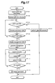
- FIG. 17 is a flowchart illustrating a procedure of a data generating process performed by the information processing apparatus of FIG. 1.
- a preliminary management table is generated.
- the operator modifies the management table based on the preliminary management table.
- 2-D image data is generated for output, based on the 3-D data in the CAD file.
- Step 101 the parts tree information in the CAD file is read in.
- Step 102 parts tree structure diagram is displayed on the display.
- Step 104 the control proceeds to Step 104 to execute the corresponding processes.
- Step 105 the control proceeds to Step 105 to generate the preliminary management table.
- Step 107 the control returns to Step 103 .
- Step 107 the preliminary management table is displayed on the display in a modifiable state.
- the management data generator When the operator modifies the management table, the management data generator generates management table data with the modification at Step 108 . Then the control proceeds to Step 109 .
- Step 109 3-D data of parts and ASSEMBLY specified as output items in the management table is retrieved from the 3-D data in the CAD file. Then, at Step 110 , bitmap image data of the parts and ASSEMBLY is output based on the 3-D data. At Step 111 , the bitmap image data is stored as 2-D data file in the hard disk. The above-described process is repeated from the first line data to the last line data in the management table. When it is determined that the process of the last line data is completed at Step 112 , the control proceeds to Step 113 in order to execute a process of adding a repeat command according to the operator's instruction.
- FIG. 18 is a flowchart illustrating a procedure of an assembly scene output process at a PC for assembly scene output of FIG. 2.
- a scenario table is generated based on the management data file, based on which an assembly scene is output.
- a scenario table is generated based on the scenario file, in order to output the assembly scene.
- Step 202 When the scenario file is not found at Step 201 , the control proceeds to Step 202 in order to read out the management data file.
- Step 203 scenario table is generated on the RAM based on the management table.
- Step 204 the scenario file is read out at Step 204 .
- the scenario table is generated on the RAM, and the control proceeds to Step 205 .
- Step 205 the authoring unit reads in the scenario table on the RAM. Then, at Step 206 , 2-D data file, tool data file, and voice data file are read out from the hard disk, in order to retrieve the image data of parts/ASSEMBLY/finished product, image data of tools, and voice data that are specified in the scenario table. Then, at Step 207 , output control for the image data and voice data is performed according to the scenario table. When an assembly scene is output on the screen, voice data explaining the scene is output at the same time. When it is determined that repeating is instructed at Step 208 , the control returns to Step 205 , to re-output the assembly scene.
- FIGS. 19 and 20 are flowcharts illustrating a procedure of generating a scenario table from the management data of FIG. 18.
- data in the management table is expanded on the RAM in order to generate a scenario table for each scene. Then, by analyzing the data, information necessary for the output control at the authoring unit is set at the scenario table.
- Step 301 an initializing process is executed, where 1 is assigned to both line M (for the entire management table) and line N (for each scene).
- Step 302 data at line M in the management table is read in.
- the control proceeds to Step 304 .
- assembly order number (No.) of the line M is assigned to scene number S.
- Step 305 data of line M is stored as line N of the scene number S in the scenario table. Then, the control proceeds to Step 306 .
- Step 306 entire line number M is incremented by one to move to the next line.
- Step 307 data in line M of the management table is read in.
- Step 308 it is determined whether the management table is completed. When it is not completed, the control proceeds to Step 309 to check whether the assembly order number (No.) of line M equals to scene number S (i.e., to check whether the scene has not changed). If the scene has changed, the control proceeds to Step 310 to increment the entire line number M by one, and to assign 1 to scene individual line number N. Then, the control returns to Step 302 to process a table in the next scene.
- Step 311 the scene individual line number N is incremented by one. Then the control proceeds to Step 305 to store the data in the table. The above-described process is performed until the management table is completed.
- Steps 303 and 308 the control proceeds to a data analyzing process for each scene, which starts at Step 401 of FIG. 20.
- Step 401 of FIG. 20 an initialization process is performed, where 1 is assigned to both scene number S and scene individual line number N.
- Step 402 Data in line N is read in.
- Step 403 it is checked whether the table in the scene is not completed (i.e., more line(s) need to be read in). If the table in the scene is not completed, the control proceeds to Step 404 to set the sum value of setup time (TIME) of the earlier lines from line N within the same scene, the sum value being regard as a stopping time (display waiting time). Then, the control proceeds to Step 405 .
- TIME setup time
- Step 405 it is checked whether the setup time (TIME) for line N is set to 0.
- the control proceeds to Step 406 to set the setup time (TIME) as the display time.
- the control proceeds to Step 407 to check whether the moving direction (move) is 0.
- the control proceeds to Step 408 to set the sum value setup time (TIME) after the current line as the display time.
- the control proceeds to Step 409 . Then, at Step 409 , the first appearing value of the setup time (TIME) that is not 0, after the current line, is set as the display time.
- Step 410 set the image display level order of the current line.
- the display level orders (dept) in all lines are not 0, the given value becomes the display level order.
- the display level orders are set according to the order of the line numbers.
- Step 411 scene individual line number N is incremented by one. Then, the control returns to Step 402 to move to the analyzing process for the next line.
- Step 412 the control proceeds to Step 412 to check whether the tables for all scenes are completed.
Abstract
Description
- 1. Field of the Invention
- This invention relates to an information processing apparatus, a program for product assembly process display, and a method for product assembly process display, that output scenes on a screen, for assembling a product made from a plurality of parts.
- 2. Description of Related Art
- In order to effectively explain steps of a product assembly made from a plurality of parts, to a worker at the assembly line, video images of assembly work using real parts have been used. However, creation of such a learning video requires an immense effort. When an information processing apparatus is used to display virtual parts illustrating an assembly scene on a display, a cost cutting effect can be expected by omitting the video capturing time. However, this process is also burdensome, since image data for each part needs to be newly prepared. In contrast, when computer assisted design (CAD) data generated during a designing step is applied to image data of parts, it is possible to omit the process of generating the image data, thereby lowering the cost of generating data for assembly scene output.
- However, image used in a 2-D (two-dimensional) CAD is an illustrated view from one direction, therefore it is not necessarily the suitable image for the assembly scene. Also, 2-D image may be difficult to easily illustrate the assembly scene. Although it is possible to select an arbitrarily angle when a 3-D (three-dimensional) CAD image is applied, in order to easily illustrate the assembly scene, an enormous amount of data needs to be processed for outputting the assembly scene, thereby making it difficult for a PC for a regular office use to output the data, and eventually increasing the cost.
- The present invention addresses the above-described problems of the conventional technologies. The main purpose of the invention is to provide an information processing apparatus, a program for product assembly process display, and a method for product assembly process display, that use only a small amount of data handling the output of assembly scenes, output assembly scene with a low processing capability, apply data generated from a designing process, and simply illustrate the assembly scene using image of a part from an angle suitable for the assembly scene display.
- In order to serve the above-described purpose, the image processing apparatus is provided with a 3-D data memory that stores 3-D data related to a product assembled by a plurality of parts, a data retriever that retrieves 3-D data for each part from the 3-D data related to the product, a 2-D data generator that generates 2-D data illustrating an image of each part viewed from a predetermined direction based on the 3-D data of each part, a 2-D data memory that stores 2-D data for each part, and a management data generator that generates management data describing steps to allow another information processing apparatus to output an assembly scene on a display, by using the 2-D data of each part. Accordingly, it is possible to lighten the load of assembly scene output, as well as reducing the cost by using a general PC as the information processing apparatus to output the assembly scene.
- The present invention is further described in the detailed description which follows, with reference to the noted plurality of drawings by way of non-limiting examples of exemplary embodiments of the present invention, in which like reference numerals represent similar parts throughout the several views of the drawings, and wherein:
- FIG. 1 is a schematic block diagram illustrating an information processing apparatus according to the present invention;
- FIG. 2 is a schematic block diagram illustrating a PC for assembly scene output of FIG. 1;
- FIG. 3 is a schematic diagram illustrating a display output at the PC for outputting the assembly scene of FIG. 2;
- FIG. 4 is another schematic diagram illustrating a display output at the PC for outputting the assembly scene of FIG. 2;
- FIG. 5 is another schematic diagram illustrating a display output at the PC for outputting the assembly scene of FIG. 2;
- FIG. 6 is another schematic diagram illustrating a display output at the PC for outputting the assembly scene of FIG. 2;
- FIG. 7 illustrates a control status of the display output at the PC for outputting the assembly scene of FIG. 2;
- FIG. 8 illustrates a display screen of a parts tree structure diagram at the information processing apparatus for generating data of FIG. 1;
- FIG. 9 illustrates a display screen of a specified range of an outputting part at the information processing apparatus for generating data of FIG. 1;
- FIG. 10 illustrates another display screen of a parts tree structure diagram at the information processing apparatus for generating data of FIG. 1;
- FIG. 11 illustrates another display screen of a parts tree structure diagram at the information processing apparatus for generating data of FIG. 1;
- FIG. 12 illustrates another display screen of a parts tree structure diagram at the information processing apparatus for generating data of FIG. 1;
- FIG. 13 illustrates a preliminary management table generated by a management table generator of FIG. 1;
- FIG. 14 illustrates a management table stored in a management data file of FIG. 1;
- FIG. 15 illustrates a management table for output, stored by a management data file for output of FIG. 1;
- FIG. 16 illustrates a scenario table generated on a RAM of FIG. 2;
- FIG. 17 is a flowchart illustrating a procedure of a data generating process performed by the information processing apparatus of FIG. 1;
- FIG. 18 is a flowchart illustrating a procedure of an assembly scene output process at a PC for assembly scene output of FIG. 2;
- FIG. 19 is a flowchart illustrating a procedure of generating a scenario table from management data of FIG. 18; and
- FIG. 20 is a flowchart illustrating a procedure of generating a scenario table that follows FIG. 19.
- The embodiment of the present invention is explained in the following, in reference to the above-described drawings.
- FIG. 1 is a schematic block diagram illustrating an information processing apparatus according to the present invention.
Information processing apparatus 1 generates data to enable PC 2 for assembly scene output (another information processing apparatus) 2 to output on a screen.Information processing apparatus 1 also reads outprogram file 4 stored inhard disk 3.CPU 5 executes execute a predetermined process in accordance withprogram file 4. - In
information processing apparatus 1,CAD file 7, storing 3-D data related to an assembled product made of plurality of parts, is stored in hard disk 3 (3-D data memory). This 3-D data for each part is retrieved by parts data retriever (data retriever) 8, from the 3-D data related to the assembled products. Based on the retrieved 3-D data for each part, 2-D bitmap image data illustrating a part image from a predetermined direction is generated by bitmap output unit (2-D data generator) 9, and 2-D data file 10 storing the image data for each part is stored in hard disk (2-D data memory) 3. -
CAD file 7 is an output from 3-D CAD apparatus 12 in a data format of XVL (eXtensible Virtual world description Language).CAD file 7 stores 3-D data as well as parts tree information illustrating a tree-shaped assembly process from a plurality of parts to a final assembled product. -
Parts data retriever 8 retrieves 3-D data from the CAD file, the data corresponding to parts and an “ASSEMBLY” (preliminarily assembled product) that is constructed during an assembly procedure from individual parts to the final assembled product. Based on the obtained 3-D data of the ASSEMBLY,bitmap output unit 9 generates 2-D image data. - Based on the parts tree information of
CAD file 7,parts data retriever 8 specifies parts and ASSEMBLY in order to retrieve data.Parts tree manager 13 analyzes the retrieved parts tree information, whiledisplay controller 14 displays the parts tree structure diagram ondisplay 15. Then, an operator usesoperation unit 16, including a keyboard and pointing device, on the parts tree structure diagram, in order to specify the retrieving parts and ASSEMBLY. Detail illustrations of the above are later provided using FIGS. 8-12. - Upon generating 2-D data, specifying a conversion condition such as a view point location and projection angle for the 2-D imaging, is performed as follows. First,
display 15 displays the parts and ASSEMBLY images visualized from 3-D data, so that the operator views the display and inputs an appropriate conversion condition usingoperation unit 16. This input information is then transmitted from angle/enlargement setter 18 toparts data retriever 8 andbitmap output unit 9 to generate 2-D image data based on the specified conversion condition. Similarly, to specify display sizes of parts and ASSEMBLY, the operator views an image displayed ondisplay 15 and inputs an appropriate display size usingoperation unit 16. This input information is then transmitted from angle/enlargement setter 18 tobitmap output unit 9 to generate 2-D image data based on the specified display size. - In addition, in
information processing apparatus 1,management data generator 20 generates a management table (management data) describing steps to output the assembly procedure on a screen, by using 2-D data for each part and ASSEMBLY.Management data generator 20 first generates a preliminary management table based on parts tree information ofCAD file 7, which is stored inhard disk 3, as preliminary management data file 21. This preliminary management table is also displayed ondisplay 15 bydisplay controller 14 so that the operator can alter the contents usingoperation unit 16. This input information atoperation unit 16 is transmitted tomanagement data generator 20, and modified management table is stored inhard disk 3 as management data file 22. Further,management data generator 20 generates an output management table based on the modified management table, which is stored inhard disk 3 as output management data file 23. Detail illustrations of the above are later provided using FIGS. 13-15. - FIG. 2 is a schematic block diagram illustrating a configuration of PC for assembly scene output of FIG. 1. 2-D data file 10 and output management data file 23 that are generated by
information processing apparatus 1 of FIG. 1, are stored in hard disk (2-D data memory, management data memory) 31. ThisPC 2 for assembly scene output outputs an assembly procedure on a screen, using the data file, i.e.,Program file 23 stored inhard disk 31 is read out to execute a predetermined process atCPU 33. - In this PC for
assembly scene output 2, management data file 23 stored inhard disk 31 is retrieved, so that the management table within the file is stored inRAM 34 as a scenario table. The table is then analyzed bytable analyzer 35, and the information actually needed for the assembly scene output is setup in the scenario table. Based on this scenario table, authoringunit 36 controls the assembly scene output. Inauthoring unit 36,data retriever 37 retrieves image data of necessary parts, ASSEMBLY, and a completed product from 2-D data file 10, according to the scenario table. By processing the image data according to the steps described in the scenario table, it is possible fordisplay controller 38 to display the assembly scene ondisplay 39. The scenario table, with the necessary setup information processed bytable analyzer 35, is added to scenario file 41 byscenario file generator 40, and stored inhard disk 31. Therefore, when the assembly scene is re-output, thisscenario file 41 is read out fromhard disk 31, and the scenario table is generated inRAM 34. The detail of the scenario table is later described using FIG. 16. In addition, the scenario file stores information for each item described in the scenario table. - Moreover, in PC for
assembly scene output 2, tool data file 42 storing the image data of tools used in the assembly process is stored in hard disk (tool data memory) 31. According to the scenario table generated based on the management table in management data file 23, authoringunit 36 reads out image data of the corresponding tools, so that the tool image is output on a screen together with the images of parts and ASSEMBLY. - Further, in PC for
assembly scene output 2, voice data file 43 storing voice data is stored in hard disk (voice data memory) 31. According to the scenario table, authoringunit 36 reads out corresponding voice data, and speaker (voice output unit) 45 outputs necessary voices viavoice controller 44 during the screen output of parts and ASSEMBLY images. - FIGS. 3-6 are schematic illustrations of screen output by the PC for assembly scene output shown in FIG. 2. In this example, one part among a plurality of parts moves, image data according to two parts or more than two parts is overlapped each other. Then, when a plurality of data is overlapped entirely, a plurality of parts which indicate the overlapped final stage are replaced by one image of ASSEMBLY and output on the screen. Also, in a scene where a small part is introduced, the images of parts and ASSEMBLY are replaced with a partially enlarged image on the output screen. Further, the image of the corresponding part moves according to the direction of the part assembly on the output screen.
- Images of parts and ASSEMBLY are displayed overlapping in the front/back direction, with a transparent background. The moving image has specified coordinates of move starting location and move ending location. At the move ending location, the parts are displayed assembled to a fixed image. Moreover, images of parts and assembly are displayed as 3-D color images with a shading method in real operation, even though they are illustrated only with lines in these figures.
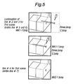
- FIG. 3 illustrates the first scene where ASSEMBLY WK1 is assembled from parts A and B. First, an image of part A (A.bmp) is stably displayed in a location within a display frame. Simultaneously, an image of part B (B.bmp) starts moving from a left side position outside of the display frame so that, within the display frame that is actually output on the screen, part B appears from the left edge and moves toward the right direction to be attached to a back surface of part A. This constructs ASSEMBLY WK1, thus images of parts A and B are replaced with an ASSEMBLY image (WK1.bmp).
- FIGS. 4 and 5 illustrate the second scene where ASSEMBLY WK2 is constructed by attaching part C (a screw connecting parts A and B) to ASSEMBLY WK1 using a driver. First, a partially enlarged image of ASSEMBLY WK1 (WK1-1.bmp) is displayed. Simultaneously, an image of part C (C.bmp) and an image of a driver (Driver.bmp) start moving from a right side position outside of the display frame so that, within the display frame that is actually output on the screen, part C and the driver appear from the right edge and move toward the left direction to attach part C to ASSEMBLY WK1. This constructs ASSEMBLY WK2, thus images are replaced with an enlarged image of ASSEMBLY WK2 (WK2-1.bmp), having part C inserted into a hole of ASSEMBLY WK1 (in reality, parts A and B).
- FIG. 6 illustrates the third scene where ASSEMBLY WK2 is completed with attaching part D. First, an image of ASSEMBLY WK2 (WK2.bmp) is displayed. Simultaneously, an image of part D (D.bmp) starts moving from a right side position outside of the display frame so that, within the display frame that is actually output on the screen, part D appears from the right edge and moves toward the left direction in order to be attached to ASSEMBLY WK2. This completes ASSEMBLY WK2, thus images are replaced with an image of completed product TOP (TOP.bmp), having part D inserted into a hole of ASSEMBLY WK2 (in reality, part A).
- FIG. 7 illustrates the control of screen output at the PC for assembly scene output of FIG. 2. This example uses the first scene illustrated in FIG. 3, where all images within the same scene (A.bmp, B.bmp, and WK1.bmp) start their processes simultaneously. The image of part A (A.bmp) and image of part B (B.bmp) are displayed from the beginning, and the image of part B continuously moves during the display time. The display image of the ASSEMBLY (WK1.bmp) is stopped until the display time of parts A and B ends, and is replaced with the images of parts A and B when the stopping time expires.
- FIG. 8 illustrates a display screen of the parts tree structure diagram at the information processing apparatus for generating data shown in FIG. 1. This parts tree structure diagram illustrates a layered structure from parts via ASSEMBLIES to a completed product. Based on the parts tree information stored in the CAD file, parts and ASSEMBLIES can be selected to be the assembly scene image output. In this parts tree structure diagram, parts comprising an ASSEMBLY are displayed subordinately to the ASSEMBLY. Thus, by specifying one ASSEMBLY, individual images of parts comprising the ASSEMBLY, and the constructed image with the constructing parts are output. Since this parts tree structure diagram is generated in a structure in accordance with the assembly steps, and facilitates the visual understanding of the product configuration, it is possible to simply and accurately specify an item for output, even though the product has many parts and complicated configuration.
- FIG. 9 illustrates a display screen of a specified range of an outputting part at the information processing apparatus for generating data of FIG. 1. Using this screen, it is possible to individually specify a part/ASSEMBLY and a range. Starting
ASSY display column 51 and endingASSY display column 52 display a starting part and an ending part specified at the screen of the parts tree structure diagram. By controlling addingbutton 53, the specifying range can be displayed on list (starting/ending ASSY specifying list) 54, which will be used to setup the following process. In order to specify the unnecessary range, such an item is selected fromlist 54, and deletebutton 55 is pressed. Then, the item is deleted from the list and the specified range is canceled. - FIGS. 10, 11, and 12 illustrate other examples of the display screen of the parts tree structure diagram at the information processing apparatus for generating data of FIG. 1. As shown in FIG. 10, when only the starting item is specified without specifying the ending item, only single item is selected. When the single item is an ASSEMBLY (ASSY1), the constructed image and images of the configuring parts (Parts 1-4) are output. When both starting and ending items are selected, as shown in FIG. 11, all the parts and ASSEMBLY between the selected items are chosen. Therefore, an image of the ASSEMBLY (ASSY1), images of parts subordinate to the ASSEMBLY (Parts 1-4), an image of
Part 10 and a constructed image of the ASSEMBLY (ASSY2) are output. As shown in FIG. 12, when only the ending item is specified without specifying the starting item, only single item is selected, outputting the image ofPart 4. Accordingly, it is possible to freely specify an output item on the parts tree structure diagram. When the ending item is above the starting item, it is treated as an error, and the output process is not performed. - FIG. 13 illustrates a preliminary management table generated by the management table generator shown in FIG. 1. This preliminary management table is generated based on the parts tree information in the CAD file. By associating the information with the name of outputting parts, ASSEMBLY, and finished product (“Part”), the table stores the assembly order number specifying the processing order for an assembly scene output (“No”.), setup time indicating a waiting time until starting a display of the next image (“Time”), moving direction information (image moving information) for displaying the move of the output image (“move”), display change specifying information that specifies the necessity of a process to change display location, display angle, and display size of the output image (“view change”), internal identifying information for the output (“UID”), composition element information differentiating a part from an ASSEMBLY (“Comp fig”), display layer ordering information that specifies fore-and-aft location when a plurality of output images are displayed on the same scene (“dept”), type information indicating an item that does not have an output image in the 2-D data file, e.g., a tool (“kind”), and reverse expansion negligence information that does not allow the output during the screen output of a dissembling scene in the opposite order from an ASSEMBLY (“Non rev”).
- When a plurality of items have the same assembly order number (No.), they construct the same scene and their processes start at the same time. The setup time (Time) uses seconds. Moving direction information (move) specifies “0” for fixed display, “1” for moving from right to left, and “1” for moving from left to right. Display change specifying information (view change) specifies “1” for changing display, which is later followed by a screen display specifying a specific change, in order for the operator to perform the specified operation. Internal identifying information (UID) is automatically added and therefore unchangeable. Composition element information (Comp fig) specifies “1” for a part, and “2” for an ASSEMBLY. In display layer ordering information (dept), when a number other than “0” is specified, the number becomes the display layer order, having the greater number displayed in the front. When only “0” is specified in the same scene, the actual display layer order is set according to the order of the line, having the latest in number displayed in the front. Reverse expansion negligence information (Non rev) sets “1” for non-display.
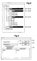
- FIG. 14 illustrates a management table stored in a management data file of FIG. 1. This management table is modified when the operator inputs the modification based on the preliminary management table. The information items to be stored are the same as the preliminary management table. In this example, ASSEMBLY WK1 from parts A and B, ASSEMBLY WK2 from ASSEMBLY WK1 and part C, and a driver are added. Considering the actual assembly steps, setup time (Time) and moving direction information (move) are modified in this management table. Further, display change specifying information (view change) is also modified to have an enlarged display of ASSEMBLY WK1, to match the small size of part C in the second scene. In the last line, repeat specifying information (R) is added in order to repetitively output the series of assembly scenes on the screen. Moreover, the management data file can be modified by a multi-use spread sheet application, when the file has a CSV format.
- FIG. 15 illustrates a management table for output, stored by a management data file for output of FIG. 1. This management table for output stores, in accordance with file names (filename) for output images stored in the 2-D data file, assembly order number (No.), setup time (Time), moving direction information (move), display layer ordering information (dept), through color information (through color), and reverse expansion neglect information (Non rev). Through color information (through color) specifies the background color. In this example, black color is specified according to the RGB primary-color hexadecimal display. Others are the same as the above-described management table.
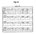
- FIG. 16 illustrates a scenario table generated on a RAM of FIG. 2. This scenario table is used by the authoring unit to output the assembly scene, and is generated based on the management table of the management file. This scenario table is prepared for each scene, setting file name within the management table (filename), moving direction information (move), display layer ordering information (dept), and information regarding display time, stopping time, displaying coordinates, and moving coordinates that are analyzed by the management table. Information for each display time and stopping time is calculated from the setup time (Time) in the management table. Information for each displaying coordinates (moving starting location) and moving coordinates (moving ending location/moving amount) is calculated from moving direction information of the management table (move), thereby setting specific coordinates. In addition, it is possible to setup trail information when an image has a curvilinear move.
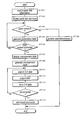
- FIG. 17 is a flowchart illustrating a procedure of a data generating process performed by the information processing apparatus of FIG. 1. In this example, when an output item is specified from the parts tree structure diagram, a preliminary management table is generated. Further, when the bitmap output is requested, the operator modifies the management table based on the preliminary management table. Upon completing the modifying process, 2-D image data is generated for output, based on the 3-D data in the CAD file.
- At Step 101, the parts tree information in the CAD file is read in. At Step 102, parts tree structure diagram is displayed on the display. When other processes are selected on the display screen on the display at Step 103, the control proceeds to Step 104 to execute the corresponding processes. When a part is selected at Step 103, the control proceeds to Step 105 to generate the preliminary management table. Then, when the bitmap output is instructed at Step 106, the control proceeds to Step 107. When the bitmap output is not instructed at Step 106, the control returns to Step 103.
- At Step 107, the preliminary management table is displayed on the display in a modifiable state. When the operator modifies the management table, the management data generator generates management table data with the modification at Step 108. Then the control proceeds to Step 109.
- At Step 109, 3-D data of parts and ASSEMBLY specified as output items in the management table is retrieved from the 3-D data in the CAD file. Then, at Step 110, bitmap image data of the parts and ASSEMBLY is output based on the 3-D data. At Step 111, the bitmap image data is stored as 2-D data file in the hard disk. The above-described process is repeated from the first line data to the last line data in the management table. When it is determined that the process of the last line data is completed at Step 112, the control proceeds to Step 113 in order to execute a process of adding a repeat command according to the operator's instruction.
- FIG. 18 is a flowchart illustrating a procedure of an assembly scene output process at a PC for assembly scene output of FIG. 2. In this example, when a scenario file is not found in the hard disk at the first assembly scene output, a scenario table is generated based on the management data file, based on which an assembly scene is output. When the scenario file is already found in the hard disk, a scenario table is generated based on the scenario file, in order to output the assembly scene.
- When the scenario file is not found at Step 201, the control proceeds to Step 202 in order to read out the management data file. At the following Step 203, scenario table is generated on the RAM based on the management table. At the same time, from a data analysis, necessary information is set in the scenario table. Then the control proceeds to Step 205. However, when the scenario file is found at Step 201, the scenario file is read out at Step 204. Then, the scenario table is generated on the RAM, and the control proceeds to Step 205.
- At Step 205, the authoring unit reads in the scenario table on the RAM. Then, at Step 206, 2-D data file, tool data file, and voice data file are read out from the hard disk, in order to retrieve the image data of parts/ASSEMBLY/finished product, image data of tools, and voice data that are specified in the scenario table. Then, at Step 207, output control for the image data and voice data is performed according to the scenario table. When an assembly scene is output on the screen, voice data explaining the scene is output at the same time. When it is determined that repeating is instructed at Step 208, the control returns to Step 205, to re-output the assembly scene.
- FIGS. 19 and 20 are flowcharts illustrating a procedure of generating a scenario table from the management data of FIG. 18. In this example, data in the management table is expanded on the RAM in order to generate a scenario table for each scene. Then, by analyzing the data, information necessary for the output control at the authoring unit is set at the scenario table.
- First, at Step 301, an initializing process is executed, where 1 is assigned to both line M (for the entire management table) and line N (for each scene). At Step 302, data at line M in the management table is read in. When it is determined that more line(s) can be read in (i.e., the management table is not completed) at Step 303, the control proceeds to Step 304. At Step 304, assembly order number (No.) of the line M is assigned to scene number S. At the following Step 305, data of line M is stored as line N of the scene number S in the scenario table. Then, the control proceeds to Step 306.
- At Step 306, entire line number M is incremented by one to move to the next line. At Step 307, data in line M of the management table is read in. At Step 308, it is determined whether the management table is completed. When it is not completed, the control proceeds to Step 309 to check whether the assembly order number (No.) of line M equals to scene number S (i.e., to check whether the scene has not changed). If the scene has changed, the control proceeds to Step 310 to increment the entire line number M by one, and to assign 1 to scene individual line number N. Then, the control returns to Step 302 to process a table in the next scene.
- In contrast, when it is determined that the scene has not changed at Step 309, the control proceeds to Step 311, where the scene individual line number N is incremented by one. Then the control proceeds to Step 305 to store the data in the table. The above-described process is performed until the management table is completed. When it is determined that the management table is completed at Steps 303 and 308, the control proceeds to a data analyzing process for each scene, which starts at Step 401 of FIG. 20.
- At Step 401 of FIG. 20, an initialization process is performed, where 1 is assigned to both scene number S and scene individual line number N. At the following Step 402, Data in line N is read in. Then, at Step 403, it is checked whether the table in the scene is not completed (i.e., more line(s) need to be read in). If the table in the scene is not completed, the control proceeds to Step 404 to set the sum value of setup time (TIME) of the earlier lines from line N within the same scene, the sum value being regard as a stopping time (display waiting time). Then, the control proceeds to Step 405.
- At Step 405, it is checked whether the setup time (TIME) for line N is set to 0. When the setup time (TIME) is not 0, the control proceeds to Step 406 to set the setup time (TIME) as the display time. When the setup time (TIME) is 0, the control proceeds to Step 407 to check whether the moving direction (move) is 0. When the moving direction (move) is 0 and the image of the current line is not to be moved, the control proceeds to Step 408 to set the sum value setup time (TIME) after the current line as the display time. When the moving direction (move) is not 0, and the image of the current line is to be moved, the control proceeds to Step 409. Then, at Step 409, the first appearing value of the setup time (TIME) that is not 0, after the current line, is set as the display time.
- When the above-described setup process for the display time is completed, the control proceeds to Step 410 to set the image display level order of the current line. In this example, when the display level orders (dept) in all lines are not 0, the given value becomes the display level order. When all the display level orders are 0, the display level orders are set according to the order of the line numbers. Next, at Step 411, scene individual line number N is incremented by one. Then, the control returns to Step 402 to move to the analyzing process for the next line. When it is determined that the table in the scene is completed at Step 403, the control proceeds to Step 412 to check whether the tables for all scenes are completed. When the tables for all scenes are not completed, scene number S is incremented by one and the scene individual line number N becomes 1. Then, the control returns to Step 402 to proceeds to a process for another scene. In contrast, when it is determined that the tables for all scenes are completed at Step 412, a procedure is performed in accordance with whether the repeat command (R) exists, which completes the process.
- It is noted that the foregoing examples have been provided merely for the purpose of explanation and are in no way to be construed as limiting of the present invention. While the present invention has been described with reference to exemplary embodiments, it is understood that the words which have been used herein are words of description and illustration, rather than words of limitation. Changes may be made, within the purview of the appended claims, as presently stated and as modified, without departing from the scope and spirit of the present invention in its aspects. Although the present invention has been described herein with reference to particular structures, materials and embodiments, the present invention is not intended to be limited to the particulars disclosed herein; rather, the present invention extends to all functionally equivalent structures, methods and uses, such as are within the scope of the appended claims.
- The present invention is not limited to the above-described embodiments, and various variations and modifications may be possible without departing from the scope of the present invention.
- This application is based on the Japanese Patent Application No. 2002-115097 filed on Apr. 17, 2002, entire content of which is expressly incorporated by reference herein.
Claims (17)
Applications Claiming Priority (2)
| Application Number | Priority Date | Filing Date | Title |
|---|---|---|---|
| JP2002115097A JP3939189B2 (en) | 2002-04-17 | 2002-04-17 | Information processing apparatus, product assembly process display program, and product assembly process display method |
| JP2002-115097 | 2002-04-17 |
Publications (2)
| Publication Number | Publication Date |
|---|---|
| US20030197700A1 true US20030197700A1 (en) | 2003-10-23 |
| US7170509B2 US7170509B2 (en) | 2007-01-30 |
Family
ID=29207674
Family Applications (1)
| Application Number | Title | Priority Date | Filing Date |
|---|---|---|---|
| US10/327,876 Expired - Fee Related US7170509B2 (en) | 2002-04-17 | 2002-12-26 | Information processing apparatus, program for product assembly process display, and method for product assembly process display |
Country Status (2)
| Country | Link |
|---|---|
| US (1) | US7170509B2 (en) |
| JP (1) | JP3939189B2 (en) |
Cited By (12)
| Publication number | Priority date | Publication date | Assignee | Title |
|---|---|---|---|---|
| US20050149865A1 (en) * | 2004-01-06 | 2005-07-07 | Microsoft Corporation | Positionally encoded document image analysis and labeling |
| US20060267980A1 (en) * | 2005-05-30 | 2006-11-30 | Fujitsu Limited | CAD method, CAD system and program storage medium storing CAD program thereof |
| US20070008621A1 (en) * | 2005-07-07 | 2007-01-11 | Naoyuki Satoh | Selection of a part in image showing three dimensional object |
| US20070198367A1 (en) * | 2006-02-17 | 2007-08-23 | Junichi Yamagata | Parts catalog system, method and program to generate parts catalog, and recording medium storing the program |
| US20070200846A1 (en) * | 2004-03-30 | 2007-08-30 | Lexer Research Inc. | Object Display Device And Object Display Program |
| US20080062170A1 (en) * | 2006-09-07 | 2008-03-13 | Naoyuki Satoh | Part identification image processor, program for generating part identification image, and recording medium storing the same |
| WO2008129254A1 (en) * | 2007-04-19 | 2008-10-30 | Royal Mail Group Limited | Work rate indicator system |
| US20090187895A1 (en) * | 2008-01-18 | 2009-07-23 | Panasonic Corporation | Device, method, program, and recording medium for converting program |
| US20110307090A1 (en) * | 2010-06-09 | 2011-12-15 | Fujitsu Limited | Tolerance analyzing apparatus, designing apparatus, viewer apparatus, and assembly order converting method |
| US20120100520A1 (en) * | 2010-10-25 | 2012-04-26 | Electronics And Telecommunications Research Institute | Assembly process visualization apparatus and method |
| US20140162224A1 (en) * | 2012-11-28 | 2014-06-12 | Vrsim, Inc. | Simulator for skill-oriented training |
| US11423799B2 (en) * | 2019-07-03 | 2022-08-23 | Rockwell Automation Technologies, Inc. | Systems and methods for generating custom assembly instructions for product packages |
Families Citing this family (20)
| Publication number | Priority date | Publication date | Assignee | Title |
|---|---|---|---|---|
| US7580769B2 (en) * | 2003-08-28 | 2009-08-25 | The Boeing Company | Tool operator instructions system and method |
| JP2006026790A (en) * | 2004-07-15 | 2006-02-02 | Fanuc Ltd | Teaching model production device |
| US7295201B2 (en) * | 2005-09-29 | 2007-11-13 | General Electronic Company | Method and system for generating automated exploded views |
| KR100753536B1 (en) * | 2006-05-04 | 2007-08-30 | 주식회사 아이너스기술 | Method for detecting 2 dimension sketch data of source model data for 3 dimension reverse modeling |
| JP4809121B2 (en) * | 2006-05-15 | 2011-11-09 | 株式会社リコー | Parts catalog creation method, parts catalog creation apparatus and program |
| JP4870474B2 (en) * | 2006-05-24 | 2012-02-08 | 株式会社リコー | Parts catalog display system and control method thereof |
| JP2008071046A (en) * | 2006-09-13 | 2008-03-27 | Ricoh Co Ltd | Device for creating three-dimensional model zoomed image |
| JP4979358B2 (en) * | 2006-12-06 | 2012-07-18 | 株式会社リコー | Image processing apparatus, image processing method, program, and storage medium |
| JP2008293469A (en) * | 2007-04-24 | 2008-12-04 | Sigma:Kk | Cad system, computer program for carrying out same, and recording medium recording computer program |
| US8938666B2 (en) * | 2007-11-14 | 2015-01-20 | International Business Machines Corporation | Support selective graphical display of system configurations using view filters |
| JP2009140404A (en) * | 2007-12-10 | 2009-06-25 | Mitsubishi Electric Engineering Co Ltd | Design knowledge reuse method, design knowledge reuse supporting device for supporting design knowledge reuse and program to be executed by design knowledge reuse supporting device |
| US8243067B2 (en) * | 2008-02-21 | 2012-08-14 | Sap America, Inc | PMI data visualization |
| US20100066731A1 (en) * | 2008-09-16 | 2010-03-18 | James Calvin Vecore | Configurator Process and System |
| JP2011022847A (en) * | 2009-07-16 | 2011-02-03 | Canon Inc | Information processing apparatus and program |
| JP5532811B2 (en) * | 2009-10-02 | 2014-06-25 | 株式会社リコー | Parts catalog creation support device, program, and parts catalog creation support method |
| US20110179624A1 (en) * | 2010-01-26 | 2011-07-28 | Z-Line Designs, Inc. | Animated assembly system |
| US8704824B2 (en) * | 2010-09-29 | 2014-04-22 | Siemens Product Lifecycle Management Software Inc. | Integrated history-free and history-based modeling |
| JP2016004179A (en) * | 2014-06-18 | 2016-01-12 | 株式会社アーテック | Lesson support system |
| JP6680085B2 (en) | 2016-05-31 | 2020-04-15 | 富士通株式会社 | Display control method, display control device, and display control program |
| WO2018181229A1 (en) | 2017-03-29 | 2018-10-04 | 日本電産サンキョー株式会社 | Work description creating device for industrial robot, and work description creating method for industrial robot |
Citations (20)
| Publication number | Priority date | Publication date | Assignee | Title |
|---|---|---|---|---|
| US4757461A (en) * | 1984-01-13 | 1988-07-12 | Dr. Johannes Heidenhain Gmbh | Process for graphically representing a structure |
| US4841291A (en) * | 1987-09-21 | 1989-06-20 | International Business Machines Corp. | Interactive animation of graphics objects |
| US4985855A (en) * | 1987-08-24 | 1991-01-15 | International Business Machines Corp. | Method for producing installation instructions for three dimensional assemblies |
| US5010502A (en) * | 1986-06-07 | 1991-04-23 | Hewlett-Packard Company | Method and apparatus for generating representations of 3-dimensional objects |
| US5303337A (en) * | 1990-02-28 | 1994-04-12 | Hitachi, Ltd. | Method and device for determining a viewing perspective for image production |
| US5430837A (en) * | 1990-03-27 | 1995-07-04 | Mitsubishi Denki Kabushiki Kaisha | Mechanism conceptual drawing formation method and apparatus |
| US5459830A (en) * | 1991-07-22 | 1995-10-17 | Sony Corporation | Animation data index creation drawn from image data sampling composites |
| US5502807A (en) * | 1992-09-21 | 1996-03-26 | Tektronix, Inc. | Configurable video sequence viewing and recording system |
| US5619630A (en) * | 1994-02-28 | 1997-04-08 | Hitachi, Ltd. | Apparatus for producing exploded view and animation of assembling and method thereof |
| US5696892A (en) * | 1992-07-10 | 1997-12-09 | The Walt Disney Company | Method and apparatus for providing animation in a three-dimensional computer generated virtual world using a succession of textures derived from temporally related source images |
| US5767855A (en) * | 1997-05-19 | 1998-06-16 | International Business Machines Corporation | Selectively enlarged viewer interactive three-dimensional objects in environmentally related virtual three-dimensional workspace displays |
| US5771043A (en) * | 1990-08-22 | 1998-06-23 | Hitachi, Ltd. | Method and apparatus for displaying operating procedure |
| US5862229A (en) * | 1996-06-12 | 1999-01-19 | Nintendo Co., Ltd. | Sound generator synchronized with image display |
| US5905501A (en) * | 1993-08-18 | 1999-05-18 | Fujitsu Limited | Method of and apparatus for generating assembly view |
| US5999173A (en) * | 1992-04-03 | 1999-12-07 | Adobe Systems Incorporated | Method and apparatus for video editing with video clip representations displayed along a time line |
| US6388667B1 (en) * | 1997-03-18 | 2002-05-14 | Namco Ltd | Image generation device and information storage medium |
| US6434441B1 (en) * | 1998-04-30 | 2002-08-13 | General Electric Company | Designing and making an article of manufacture |
| US6476815B1 (en) * | 1998-10-19 | 2002-11-05 | Canon Kabushiki Kaisha | Information processing apparatus and method and information transmission system |
| US6636249B1 (en) * | 1998-10-19 | 2003-10-21 | Sony Corporation | Information processing apparatus and method, information processing system, and providing medium |
| US6636774B2 (en) * | 2000-10-13 | 2003-10-21 | Fujitsu Limited | CAD supporting apparatus, and CAD supporting program storage medium |
-
2002
- 2002-04-17 JP JP2002115097A patent/JP3939189B2/en not_active Expired - Fee Related
- 2002-12-26 US US10/327,876 patent/US7170509B2/en not_active Expired - Fee Related
Patent Citations (21)
| Publication number | Priority date | Publication date | Assignee | Title |
|---|---|---|---|---|
| US4757461A (en) * | 1984-01-13 | 1988-07-12 | Dr. Johannes Heidenhain Gmbh | Process for graphically representing a structure |
| US5010502A (en) * | 1986-06-07 | 1991-04-23 | Hewlett-Packard Company | Method and apparatus for generating representations of 3-dimensional objects |
| US4985855A (en) * | 1987-08-24 | 1991-01-15 | International Business Machines Corp. | Method for producing installation instructions for three dimensional assemblies |
| US4841291A (en) * | 1987-09-21 | 1989-06-20 | International Business Machines Corp. | Interactive animation of graphics objects |
| US5303337A (en) * | 1990-02-28 | 1994-04-12 | Hitachi, Ltd. | Method and device for determining a viewing perspective for image production |
| US5430837A (en) * | 1990-03-27 | 1995-07-04 | Mitsubishi Denki Kabushiki Kaisha | Mechanism conceptual drawing formation method and apparatus |
| US5771043A (en) * | 1990-08-22 | 1998-06-23 | Hitachi, Ltd. | Method and apparatus for displaying operating procedure |
| US5459830A (en) * | 1991-07-22 | 1995-10-17 | Sony Corporation | Animation data index creation drawn from image data sampling composites |
| US5999173A (en) * | 1992-04-03 | 1999-12-07 | Adobe Systems Incorporated | Method and apparatus for video editing with video clip representations displayed along a time line |
| US5696892A (en) * | 1992-07-10 | 1997-12-09 | The Walt Disney Company | Method and apparatus for providing animation in a three-dimensional computer generated virtual world using a succession of textures derived from temporally related source images |
| US5502807A (en) * | 1992-09-21 | 1996-03-26 | Tektronix, Inc. | Configurable video sequence viewing and recording system |
| US5905501A (en) * | 1993-08-18 | 1999-05-18 | Fujitsu Limited | Method of and apparatus for generating assembly view |
| US6295063B1 (en) * | 1994-02-28 | 2001-09-25 | Hitachi, Ltd. | Apparatus for producing exploded view and animation of assembling, and method thereof |
| US5619630A (en) * | 1994-02-28 | 1997-04-08 | Hitachi, Ltd. | Apparatus for producing exploded view and animation of assembling and method thereof |
| US5862229A (en) * | 1996-06-12 | 1999-01-19 | Nintendo Co., Ltd. | Sound generator synchronized with image display |
| US6388667B1 (en) * | 1997-03-18 | 2002-05-14 | Namco Ltd | Image generation device and information storage medium |
| US5767855A (en) * | 1997-05-19 | 1998-06-16 | International Business Machines Corporation | Selectively enlarged viewer interactive three-dimensional objects in environmentally related virtual three-dimensional workspace displays |
| US6434441B1 (en) * | 1998-04-30 | 2002-08-13 | General Electric Company | Designing and making an article of manufacture |
| US6476815B1 (en) * | 1998-10-19 | 2002-11-05 | Canon Kabushiki Kaisha | Information processing apparatus and method and information transmission system |
| US6636249B1 (en) * | 1998-10-19 | 2003-10-21 | Sony Corporation | Information processing apparatus and method, information processing system, and providing medium |
| US6636774B2 (en) * | 2000-10-13 | 2003-10-21 | Fujitsu Limited | CAD supporting apparatus, and CAD supporting program storage medium |
Cited By (16)
| Publication number | Priority date | Publication date | Assignee | Title |
|---|---|---|---|---|
| US20050149865A1 (en) * | 2004-01-06 | 2005-07-07 | Microsoft Corporation | Positionally encoded document image analysis and labeling |
| US7581171B2 (en) * | 2004-01-06 | 2009-08-25 | Microsoft Corporation | Positionally encoded document image analysis and labeling |
| US20070200846A1 (en) * | 2004-03-30 | 2007-08-30 | Lexer Research Inc. | Object Display Device And Object Display Program |
| US20060267980A1 (en) * | 2005-05-30 | 2006-11-30 | Fujitsu Limited | CAD method, CAD system and program storage medium storing CAD program thereof |
| US20070008621A1 (en) * | 2005-07-07 | 2007-01-11 | Naoyuki Satoh | Selection of a part in image showing three dimensional object |
| US20070198367A1 (en) * | 2006-02-17 | 2007-08-23 | Junichi Yamagata | Parts catalog system, method and program to generate parts catalog, and recording medium storing the program |
| US20080062170A1 (en) * | 2006-09-07 | 2008-03-13 | Naoyuki Satoh | Part identification image processor, program for generating part identification image, and recording medium storing the same |
| GB2448536B (en) * | 2007-04-19 | 2012-01-11 | Royal Mail Group Ltd | Work rate indicator system |
| WO2008129254A1 (en) * | 2007-04-19 | 2008-10-30 | Royal Mail Group Limited | Work rate indicator system |
| US20090187895A1 (en) * | 2008-01-18 | 2009-07-23 | Panasonic Corporation | Device, method, program, and recording medium for converting program |
| US20110307090A1 (en) * | 2010-06-09 | 2011-12-15 | Fujitsu Limited | Tolerance analyzing apparatus, designing apparatus, viewer apparatus, and assembly order converting method |
| US20120100520A1 (en) * | 2010-10-25 | 2012-04-26 | Electronics And Telecommunications Research Institute | Assembly process visualization apparatus and method |
| US20140162224A1 (en) * | 2012-11-28 | 2014-06-12 | Vrsim, Inc. | Simulator for skill-oriented training |
| US10388176B2 (en) * | 2012-11-28 | 2019-08-20 | Vrsim, Inc. | Simulator for skill-oriented training |
| US11170657B2 (en) | 2012-11-28 | 2021-11-09 | Vrsim, Inc. | Simulator for skill-oriented training |
| US11423799B2 (en) * | 2019-07-03 | 2022-08-23 | Rockwell Automation Technologies, Inc. | Systems and methods for generating custom assembly instructions for product packages |
Also Published As
| Publication number | Publication date |
|---|---|
| US7170509B2 (en) | 2007-01-30 |
| JP3939189B2 (en) | 2007-07-04 |
| JP2003308545A (en) | 2003-10-31 |
Similar Documents
| Publication | Publication Date | Title |
|---|---|---|
| US7170509B2 (en) | Information processing apparatus, program for product assembly process display, and method for product assembly process display | |
| US5414843A (en) | Method and system for generating a project schedule using weighted work processes | |
| DE69725346T2 (en) | DEVICE AND METHOD FOR PRODUCING A SHEET BENDING MODEL | |
| US20080109717A1 (en) | Reviewing editing operations | |
| KR20160002329A (en) | Robot simulator and file generation method for robot simulator | |
| US7027963B2 (en) | Simulation system | |
| US5649220A (en) | System and method for artwork design and production | |
| JP3347964B2 (en) | Automatic programming device and method | |
| DE102012110508A1 (en) | Robot adjustment device with 3-D display | |
| JPH0765201A (en) | Device and method for shape modeling | |
| US11321584B2 (en) | Information processing device, information processing program, and information processing method | |
| DE112008003963T5 (en) | System and method for off-line programming of an industrial robot | |
| JP3038521B2 (en) | Product drawing creation device | |
| KR20160000346A (en) | Method for configuring multiple training mode, and apparatus and computer readable recording medium using the same | |
| US5289568A (en) | Apparatus and method for drawing figures | |
| JP4731335B2 (en) | ASSEMBLY EVALUATION METHOD, SYSTEM, AND PROGRAM | |
| JPH09147131A (en) | Image layout device having cutting function of image parts | |
| US20140026056A1 (en) | Apparatus and method for interactive user software interface design | |
| JP2019171498A (en) | Robot program execution device, robot program execution method and program | |
| JP2720807B2 (en) | Scenario editing device | |
| JPH08161530A (en) | Icon preparing method and frame preparing method for dynamic image | |
| US5386506A (en) | Plotting and editing apparatus | |
| KR19980026933A (en) | Process planning method by CAD based process status visualization. | |
| US20020051000A1 (en) | Design support system facilitating process modification | |
| JP6574698B2 (en) | Information processing apparatus, data processing method for information processing apparatus, and program |
Legal Events
| Date | Code | Title | Description |
|---|---|---|---|
| AS | Assignment |
Owner name: PANASONIC COMMUNICATIONS CO., LTD., JAPAN Free format text: ASSIGNMENT OF ASSIGNORS INTEREST;ASSIGNORS:TANAKA, YUTAKA;TOSHIMA, KAZUNORI;MURANO, MINORU;AND OTHERS;REEL/FRAME:013919/0672 Effective date: 20030307 Owner name: NIPPON SYSTEMWARE CO., LTD., JAPAN Free format text: ASSIGNMENT OF ASSIGNORS INTEREST;ASSIGNORS:TANAKA, YUTAKA;TOSHIMA, KAZUNORI;MURANO, MINORU;AND OTHERS;REEL/FRAME:013919/0672 Effective date: 20030307 |
|
| FEPP | Fee payment procedure |
Free format text: PAYOR NUMBER ASSIGNED (ORIGINAL EVENT CODE: ASPN); ENTITY STATUS OF PATENT OWNER: LARGE ENTITY |
|
| FPAY | Fee payment |
Year of fee payment: 4 |
|
| FEPP | Fee payment procedure |
Free format text: PAYOR NUMBER ASSIGNED (ORIGINAL EVENT CODE: ASPN); ENTITY STATUS OF PATENT OWNER: LARGE ENTITY Free format text: PAYER NUMBER DE-ASSIGNED (ORIGINAL EVENT CODE: RMPN); ENTITY STATUS OF PATENT OWNER: LARGE ENTITY |
|
| AS | Assignment |
Owner name: PANASONIC SYSTEM NETWORKS CO., LTD., JAPAN Free format text: MERGER;ASSIGNOR:PANASONIC COMMUNICATIONS CO., LTD.;REEL/FRAME:030822/0511 Effective date: 20130306 |
|
| FPAY | Fee payment |
Year of fee payment: 8 |
|
| FEPP | Fee payment procedure |
Free format text: MAINTENANCE FEE REMINDER MAILED (ORIGINAL EVENT CODE: REM.); ENTITY STATUS OF PATENT OWNER: LARGE ENTITY |
|
| LAPS | Lapse for failure to pay maintenance fees |
Free format text: PATENT EXPIRED FOR FAILURE TO PAY MAINTENANCE FEES (ORIGINAL EVENT CODE: EXP.); ENTITY STATUS OF PATENT OWNER: LARGE ENTITY |
|
| STCH | Information on status: patent discontinuation |
Free format text: PATENT EXPIRED DUE TO NONPAYMENT OF MAINTENANCE FEES UNDER 37 CFR 1.362 |
|
| FP | Lapsed due to failure to pay maintenance fee |
Effective date: 20190130 |