US20030197781A1 - Electronic endoscope selector and electronic endoscope system - Google Patents
Electronic endoscope selector and electronic endoscope system Download PDFInfo
- Publication number
- US20030197781A1 US20030197781A1 US09/756,280 US75628001A US2003197781A1 US 20030197781 A1 US20030197781 A1 US 20030197781A1 US 75628001 A US75628001 A US 75628001A US 2003197781 A1 US2003197781 A1 US 2003197781A1
- Authority
- US
- United States
- Prior art keywords
- image
- processor
- electronic endoscope
- electronic
- indicating
- Prior art date
- Legal status (The legal status is an assumption and is not a legal conclusion. Google has not performed a legal analysis and makes no representation as to the accuracy of the status listed.)
- Granted
Links
Images


Classifications
-
- A—HUMAN NECESSITIES
- A61—MEDICAL OR VETERINARY SCIENCE; HYGIENE
- A61B—DIAGNOSIS; SURGERY; IDENTIFICATION
- A61B1/00—Instruments for performing medical examinations of the interior of cavities or tubes of the body by visual or photographical inspection, e.g. endoscopes; Illuminating arrangements therefor
- A61B1/04—Instruments for performing medical examinations of the interior of cavities or tubes of the body by visual or photographical inspection, e.g. endoscopes; Illuminating arrangements therefor combined with photographic or television appliances
-
- H—ELECTRICITY
- H04—ELECTRIC COMMUNICATION TECHNIQUE
- H04N—PICTORIAL COMMUNICATION, e.g. TELEVISION
- H04N7/00—Television systems
- H04N7/18—Closed-circuit television [CCTV] systems, i.e. systems in which the video signal is not broadcast
- H04N7/181—Closed-circuit television [CCTV] systems, i.e. systems in which the video signal is not broadcast for receiving images from a plurality of remote sources
Definitions
- the present invention relates to an electronic endoscope system which comprises a plurality of electronic endoscope units and peripheral devices, such as TV monitors, VCR's (video cassette recorder), and the like.
- the above coordinated electronic endoscope system comprises a plurality of electronic endoscope units, each of which comprises an endoscope with an elongated part for insertion into a body cavity or hollow organ, and an image-signal processing unit that processes image signals fed from an imaging device mounted at the distal end of the elongated part of the endoscope.
- the operator needs to interchange endoscopes each time the cross-reference is required.
- the operator is also required to carry out cumbersome operations to switch images displayed on the screen of the TV monitor, from the images which are fed from one electronic endoscope, to the images fed from another electronic endoscope.
- the frequent interchange of endoscopes compels a patient to endure further unnecessary discomfort.
- an object of the present invention is to provide an electronic endoscope system that enables a plurality of electronic endoscopes to share a peripheral device and integrate a plurality of electronic endoscope systems into a single coordinated electronic endoscope system. Further, another object of the present invention is to provide an electronic endoscope system which enables stored images captured by one of a plurality of electronic endoscopes, to be comparatively displayed with the live, capturing video.
- an electronic endoscope system comprises a plurality of electronic endoscopes, a storing medium, an image indicating device, an image storing processor and a comparative images indicating processor.
- the image indicating device is for indicating images captured by the electronic endoscopes.
- the image storing processor stores at least one image captured by one of the electronic endoscopes, in the storing medium as a recorded image.
- the comparative images indicating processor executes video signal processing, so that a live image being captured by one of the plurality of electronic endoscopes, and the recorded image stored in the storing medium, are comparatively indicated on a screen o f the image indicating device.
- the electronic endoscope system further comprises an electronic endoscope selector, that selects one electronic endoscope among the plurality of electronic endoscopes and feeds video signals obtained by the selected electronic endoscope to the image indicating device.
- the electronic endoscope selector can switch one electronic endoscope to another.
- the recorded image and live image are comparatively indicatable on the screen of the image indicating device by driving the comparative images indicating processor.
- the storing medium and comparative images indicating processor are disposed in the electronic endoscope selector.
- the electronic endoscope selector comprises a video-signal processor and an image parameter storing medium that stores image parameters.
- the video-signal processor executes adjustments for factors relating to tone of the image displayed on the screen of the image indicating device in accordance with the image parameters set for each of the plurality of electronic endoscopes.
- the comparative image indicating processor comprises a first and second image-indicating mode.
- the first image-indicating mode indicate the recorded image and the live image alternately on the screen of the image indicating device.
- the second image-indicating mode indicates the recorded image and the live image simultaneously on the screen.
- Each of the plurality of electronic endoscopes preferably comprise at least one control switch in order to control the comparative images indicating processor and the image storing processor.
- the control switch comprises a first and third control switch.
- the first control switch controls a storing operation of the image storing processor, and store the recording image captured by one of the plurality of electronic endoscopes in the storing medium.
- the third control switch controls a switching operation between the first and second image-indicating mode.
- the image storing processor may store a plurality of recorded images in the storing medium. Further, the control switch comprises a second control switch that selects one of the plurality of recorded images to indicate the selected image on the screen of the image indicating device.
- an electronic endoscope selector that comprises a storing medium, a video signal switching processor, an image storing processor and a comparative images indicating processor, is provided.
- the video signal switching processor selectively switches video signal among a plurality of video signals, each of which are fed from a plurality of electronic endoscopes, so that a selected video signal is fed to an image indicating device.
- the image storing processor stores at least one image captured by one of the electronic endoscopes, in the storing medium, as a recording image.
- the comparative images indicating processor comparatively indicates images of the selected video signal, or live image, and the recorded image stored in the storing medium.
- the image storing processor and comparative images indicating processor is controlled by a control signal from the electronic endoscope.
- the electronic endoscope selector comprises a video-signal processor that executes adjustment for factors relating to tone of the images displayed on a screen of the image indicating device.
- the above adjustment may be executed in accordance with image parameters set for each of the electronic endoscopes.
- the electronic endoscope further comprises an image parameter storing processor that stores the above image parameters.
- the recording image stored in the storing medium of the above system or selector is either a still or moving image.
- FIG. 1 is a schematic showing an electrical construction of an electronic endoscope system that includes an electronic endoscope selector of the present embodiment of the present invention
- FIG. 2 illustrates a display arrangement on the screen of a TV monitor in the one-image indicating mode (first image-indicating mode) of the present embodiment
- FIG. 3 illustrates a display arrangement on the screen of the TV monitor in the two-image indicating mode of the present embodiment
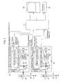
- FIG. 4 is a schematic showing an electrical construction of an electronic endoscope selector of the present embodiment.
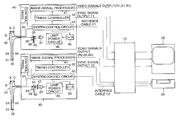
- FIG. 1 is a schematic showing an electrical construction of an electronic endoscope system of the present embodiment.
- an electronic endoscope system of the present embodiment.
- two different types of conventional electronic endoscopes are utilized in the system.
- Image-signal processing units 40 , 60 , the TV monitor (image indicating device) 25 and VCR 26 which are shared by the above two processing units, are detachably connected to the electronic endoscope selector 10 via connectors (not shown).
- the image-signal processing unit 40 processes image signals for normal color images obtained by a RGB sequential method, utilizing a white light source.
- the image-signal processing units 60 processes image signals for monochrome fluorescent images obtained by a sequential method that uses shortwave radiation source for illumination.
- An endoscope 30 is connected to the image-signal processing unit 40 and an endoscope 50 is connected to the image-signal processing unit 60 .
- Each endoscope 30 and 50 is detachably attached to the respective image-signal processing unit 40 and 60 by a scope connector (not shown).
- a scope connector not shown
- images captured by the endoscope 30 or 50 are alternatively displayed.
- the images displayed on the screen of the TV monitor 25 may be simultaneously recorded on a videocassette tape by the VCR 26 .
- a first electronic endoscope unit which comprises the endoscope 30 and the image-signal processing unit 40 , and to which the RGB sequential method is applied is described as follows:
- the light guide 34 a bundle of extra fine optical fibers, is arranged.
- An emitting end 32 is arranged at the distal end of the endoscope 30 , at one end of the light guide 34 .
- An illuminating lens (not shown) is provided in front of the emitting end 32 .
- Light is emitted from the emitting end 32 and illuminates an object via the illuminating lens.
- This illumination light is supplied from the lamp (light source) 37 , provided inside the image-signal processing unit 40 , through the light guide 34 , the other end of which is connected to the image-signal processing unit 40 via the scope connector.
- the lamp (light source) 37 provided inside the image-signal processing unit 40
- the light guide 34 the other end of which is connected to the image-signal processing unit 40 via the scope connector.
- the RGB rotational filter 38 is a flat rotating disk, which has three openings formed at regular intervals in the rotating direction. At each opening, a red (R), green (G) and blue (B) colored filter is attached respectively.
- the RGB rotational filter 38 is revolved by the motor 39 .
- the rotational axis of the filter 38 is in parallel with the optical axis of the illumination light emitted from the lamp 37 .
- the RGB rotational filter 38 is arranged so that each of the openings traverse the light path when the filter 38 is revolved. Namely, the white illumination light, which penetrates condensing lens 36 , passes through each of the R, G, B filters when each opening traverses the light path, and then concentrated on the incident end 35 .
- the illumination light that penetrates the R, G and B filters becomes R, G, B light respectively, and each sequentially made incident to the light guide 34 in regular intervals. Therefore, from the distal end of the endoscope 30 , or the emitting end 32 , the respective R, G and B light is emitted in regular intervals as illumination light.
- the intensity of the lamp 37 is controlled by the lamp power circuit 46 which is controlled by the system control circuit 43 .
- a control signal from the system control circuit 43 is a digital signal.
- the signal is converted to an analog signal by a D/A converter 45 then fed to the lamp power circuit 46 .
- the revolution of the motor 39 is controlled by a synchronized signal fed from the timing controller 42 .
- an imaging device 31 i.e., CCD
- Image sensing is carried out by utilizing the R, G and B illumination, which is emitted from the emitting end 32 . Since the illumination light is periodically emitted in the R, G and B color sequence, images corresponding to each R, G and B component are sensed by the imaging device 31 as sequential monochrome images. Captured images corresponding to each R, G and B component are transmitted as sequential RGB image signals, through the cable 33 , to the image-signal processor 41 provided in the image-signal processing unit 40 .
- Image signals input to the image-signal processor 41 are subjected to prepositional signal processing, i.e., pre-amplifying and video bandwidth filtering, S/H (sample hold), amplifying, clamping, clipping, gamma correction, etc.
- the image signals are then converted to digital image signals.
- the digital image signals are temporally stored in the image memories (not shown) for each R, G, and B component as R, G, and B image data. When one set of image data comprising R, G and B images are prepared in the image memories, the R, G, B image data is converted to analog signals and postpositional signal processing is applied.
- a filtering, amplifying, gamma correction, clamping, clipping, enhancing, signal level adjustment process and so on are executed.
- the analog image signals are then transformed to the conventional standardized RGB component format or RGB component video signals, and output to the electronic endoscope selector 10 .
- Timing for driving the imaging device 31 , and the image signal processing in the image-signal processor 41 are controlled by synchronized signals fed from the timing controller 42 .
- the timing controller 42 is controlled by the system control circuit 43 . Further, the timing controller 42 feeds the synchronization signals to the electronic endoscope selector 10 .
- the control panel 44 with a switch group (not shown) mounted in the panel, is connected to the system control circuit 43 .
- the system control circuit 43 is connected with the system control circuit 21 (refer FIG. 4) of the electronic endoscope selector 10 , via an interface cable C 1 .
- a second electronic endoscope unit which captures fluorescent images by illuminating the interior of the cavity with shortwave radiation, and comprises the endoscope 50 and the image-signal processing unit 60 , is described as follows:
- the light guide 54 a bundle of extra fine optical fibers, is provided in the endoscope 50 and one end of the light guide 54 , or emitting end 52 , is arranged at the distal end of the endoscope 50 .
- An illuminating lens (not shown) is provided in front of the emitting end 52 and shortwave radiation is emitted from the emitting end 52 and illuminates an object via the illuminating lens.
- This illumination light is supplied from the lamp (light source) 67 , provided inside the image-signal processing unit 60 , through the light guide 54 , which is connected to the image-signal processing unit 60 via the scope connector.
- the lamp (light source) 67 provided inside the image-signal processing unit 60
- the light guide 54 which is connected to the image-signal processing unit 60 via the scope connector.
- the rotational filter 58 is a flat rotating disk and, similar to the RGB rotating filter 38 in the image-signal processing unit 40 , has three openings formed at regular intervals in the rotating direction. However, unlike the RGB rotating filter 38 , the openings of the rotating filter 58 are unencumbered by filters.
- the rotational filter 58 is revolved by the motor 59 , and the rotational axis of the filter 58 is in parallel with the optical axis of the illumination light emitted from the lamp 57 . Further, the rotational filter 58 is arranged so that each of the openings traverses the light path when the filter 58 is revolved.
- the illumination light of the exciting wavelength which penetrates the excitation filter 57 and condensing lens 56 , passes through the openings when each opening traverses the light path, and is then concentrated on the incident end 55 . Therefore, the shortwave illumination light that penetrates the openings of the rotating filter 58 is sequentially made incident to the light guide 54 , and emitted in regular intervals from the distal end, or the emitting end 52 , of the endoscope 50 .
- Intensity of the lamp 67 is controlled by the lamp power circuit 66 , which is in turn controlled by the system control circuit 63 .
- a control signal from the system control circuit 63 is a digital signal.
- the signal is converted to an analog signal by D/A converter 65 , then fed to the lamp power circuit 66 .
- the revolution of the motor 59 is controlled by a synchronized signal fed from the timing controller 62 .
- an imaging device 51 such as a CCD.
- a monochrome fluorescent image is sensed with the shortwave illumination emitted from the emitting end 52 .
- the RGB sequential method monochrome images corresponding to each of the R, G and B colors are sensed, and one set of RGB color images is obtained for each revolution, when capturing fluorescent images which utilize shortwave illumination, only monochrome images corresponding to the exciting wavelength are sensed, since the illuminating light remains a constant excitation light.
- the captured fluorescent images are fed to the image-signal processor 61 , via the cable 53 arranged inside the endoscope 50 , as sequential monochrome image signals.
- the fluorescent image signals input to the image-signal processor 61 as a set of three images sequentially obtained in one revolution of the rotating filter 58 , and are processed in the same way as the RGB image signals obtained in the RGB sequential method. Namely, the fluorescent image signals input to the image-signal processor 61 are subjected to prepositional signal processing, i.e., pre-amplifying and filtering of video bandwidth, S/H (sample hold), amplifying, clamping, clipping, gamma correction, etc., and then converted to digital image signals.
- prepositional signal processing i.e., pre-amplifying and filtering of video bandwidth, S/H (sample hold), amplifying, clamping, clipping, gamma correction, etc.
- a set of digital image signals, corresponding to the three images is temporally stored in three image memories (not shown) for each image data.
- the image data is converted to analog signals and postpositional signal processing is applied.
- postpositional signal processing filtering, amplifying, gamma correction, clamping, clipping, enhancing, signal level adjustment processes and so on, are executed.
- the analog image signals are then transformed to the conventional standardized RGB component format, in other words, RGB component video signals, and fed to the electronic endoscope selector 10 .
- each component of the RGB component video signals corresponds to each of the above image signals of the three images.
- the three images are nearly identical since they are captured in quite a short time.
- the fluorescent images, as RGB component video signals from the second electronic endoscope unit are displayed on the screen the TV monitor 25 as monochrome images.
- Timing for driving the imaging device 51 , and the image signal processing in the image-signal processor 61 is controlled by synchronized signals fed from the timing controller 62 .
- the timing controller 62 and the image-signals processor 61 are controlled by the system control circuit 63 . Further, the timing controller 62 feeds the synchronization signals to the electronic endoscope selector 10 .
- the control panel 64 with a switch group (not shown) mounted in the panel, is connected to the system control circuit 63 . Further, the system control circuit 63 is connected with the system control circuit 21 (refer FIG. 4) of the electronic endoscope selector 10 , via an interface cable C 2 .
- buttons A, B and C arranged on the operating handle of each endoscope 30 and 50 are explained.
- the control buttons A, B, C are connected to the system control circuits 43 and 63 of the image-signal processing units 40 and 60 , respectively, with cables.
- corresponding operating signals are send to the respective system control circuit 43 or 63 and control signals corresponding to the operating signals are output from the system control circuits 43 or 63 .
- the control signals from the system control circuits 43 and 63 are fed to the system control circuit 21 (refer FIG. 4) of the electronic endoscope selector 10 via interface cables C 1 and C 2 .
- video signals are processed in accordance with the above control signals and output to the TV monitor 25 and VCR 26 .
- images from a selected electronic endoscope unit are displayed on an image indicating area 71 , which is a part of a screen 70 of the TV monitor 25 .
- video being captured by the endoscope 30 or 50 is displayed on the image indicating area 71 as the live image in real-time.
- the number of pixel in the imaging device 31 , 51 is smaller than that in the screen of the TV monitor 25 , thus there is margin, an area where no image is displayed, indicated as a hatched portion 72 .
- a color or fluorescent image which is comprised of a set of RGB or three monochrome images captured by an electronic endoscope, is stored in respective image memories (storing mediums) 14 r , 14 g and 14 b of the electronic endoscope selector 10 (refer FIG. 4), when the control button A of a selected electronic endoscope unit is pressed.
- a still image of the color or fluorescent image stored in the memories 14 r , 14 g and 14 b is displayed on the screen of the TV monitor 25 to confirm the above operation for about a half second, for example, and then the display recovers the (moving) video from the endoscope.
- a plurality of images can be stored in each of the image memories 14 r , 14 g and 14 b , and still color or fluorescent images can be sequentially stored with each depression of the control button A.
- the control button B is a button for displaying on screen of the TV monitor 25 the still color or fluorescent image (still video) stored in the image memories 14 r , 14 g and 14 b . Namely, when video captured by the endoscope 30 or 50 is displayed on the image indicating area 71 of the TV monitor 25 , and the control button B is depressed, the still color or fluorescent image stored in the image memories 14 r , 14 g and 14 b is displayed on the image indicating area 71 .
- image on the image indicating area 71 is switched to another still image (still video) stored in the image memories 14 r , 14 g and 14 b .
- the above image switching among the still images stored in the image memories 14 r , 14 g and 14 b , and displayed on the image indicating area 71 is executed in accordance with the stored order of the images.
- control button B when control button B is depressed while the last stored still image in the image memories 14 r , 14 g and 14 b is displayed on the image indicating area 71 , the first stored still image in the image memories 14 r , 14 g and 14 b is redisplayed. This process may be continued repeatedly until the control buttons A and B are simultaneously depressed. When the control buttons A and B are depressed simultaneously, an image displayed on the image indicating area 71 reverts to the normal video (moving image) from either endoscope 30 or 50 .
- the control button C switches an indicating mode for an image on the screen 70 .
- the display on the screen 70 alternates between a one-image indicating mode (first image-indicating mode), which indicates one image on the screen 70 as shown in FIG. 2, and a two-image indicating mode (second image-indicating mode) which indicates two images on the screen 70 as shown in FIG. 3.
- first image-indicating mode which indicates one image on the screen 70 as shown in FIG. 2
- second image-indicating mode which indicates two images on the screen 70 as shown in FIG. 3.
- both normal video (moving image as the live image ) from either endoscope 30 or 50 and a still image stored in the image memories 14 r , 14 g and 14 b , are displayed on the image indicating area 73 and 74 , together.
- a hatched portion 75 is a margin area where no image is displayed in the same way as the hatched portion 72 in FIG. 2.
- control button B When control button B is depressed while the two-images indicating mode is selected, a still image displayed on the image indicating area 74 , is switched to another still image.
- the RGB component video signal R 2 , G 2 and B 2 from the image-signal processor 61 of the image-signal processing unit 60 , are input to the switching circuits 11 r , 11 g and 11 b respectively, and the synchronization signal T 2 from the timing controller 62 is input to the switching circuit 12 . Further, a control signal from the system control circuit 63 is input to the system control circuit 21 .
- the component video signals R 2 , G 2 and B 2 from the image-signal processing unit 60 , correspond to the three fluorescent images captured during one revolution of the rotating filter 58 , and have no relation to the R, G and B color components. However, these three fluorescent images are treated in the same way the images corresponding to the R, G and B color components are treated, thus in the following description, the above three fluorescent images are treated as if they are images of the R, G and B color components.
- the switching circuits 11 r , 11 g , 11 b and 12 select a set of output signals between the component signals (R 1 , G 1 , B 1 , T 1 ) and (R 2 , G 2 , B 2 , T 2 ) in accordance with a control signal from the system control circuit 21 .
- the control signal from the system control circuit 21 relates to a control signal from a control panel 22 , which is connected to the system control circuit 21 , or a control signal from the image-signal processing units 40 or 60 .
- the synchronization signals from the switching circuit 12 are fed to a timing controller 20 .
- a timing controller 20 new synchronization signals, which are synchronized to the synchronization signals from the image-signal processing unit 40 or 60 , are generated and output.
- Timing for each circuit in the electronic endoscope selector 10 is driven by the synchronization signals from the timing controller 20 .
- the synchronization signals from the timing controller 20 are fed to the peripheral devices, i.e., the TV monitor 25 and VCR 26 , via a cable driver (a driver for signal transmission via a cable) 19 , so that each of the peripheral devices is able to synchronize with the electronic endoscope selector 10 and the electronic endoscope unit 40 or 60 .
- the timing controller 20 is controlled by the system control circuit 21 .
- the RGB component video signals fed from the switching circuits 11 r , 11 g and 11 b are fed to an A/D converter 13 , which has three channels, and converted to digital signals from the analog signals.
- the digital signals are then fed to the digital processor 15 as R, G, and B image data.
- the RGB image data may be stored in the image memories 14 r , 14 g and 14 b , respectively.
- the RGB image data are stored in the image memories 14 r , 14 g and 14 b when the control button A is depressed, as described above with reference to FIG. 1 through FIG. 3.
- the system control circuit 43 (or 63 ) of the image-signal processing unit 40 (or 60 ) outputs control signals to the system control circuit 21 .
- the system control circuit 21 controls the switching circuits 11 r , 11 g , 11 b and 12 , in accordance with the control signals from the control panel 22 or control signals from image-signal processing unit 40 (or 60 ), to switch and select the component signals and to feed the RGB component video signals (which are part of the above selected component signals) to the A/D converter 13 so that the analog signals are converted to digital signals.
- the A/D converter 13 outputs image signals or image data for the R, G and B to the image memories 14 r , 14 g , 14 b and digital processor 15 , and each of the R, G and B image data are stored in the respective image memories 14 r , 14 g and 14 b .
- the images stored in the image memories 14 r , 14 g and 14 b are output able to the digital processor 15 .
- the above image processing is applied to image data corresponding to either the video (moving image) signals, fed directly from the A/D converter 13 , or the still image signals, which are fed from the image memories 14 r , 14 g and 14 b , so that the image is displayed on the image indicating area 71 , arranged in the central part of the screen 70 , as shown in FIG. 2.
- Either video or still image signals are selected for image processing by a signal from the system control circuit 21 .
- image processing for a specific still image, stored in the image memories 14 R, 14 G and 14 B, is also selected by a signal from the system control circuit 21 .
- These control signals are provided in accordance with control signals from the image-signal processing unit, and are further generated in accordance with operations of the control buttons A, B and C on the endoscope.
- image processing is applied to both the image data that corresponds to the video (moving image) signals, fed directly from the A/D converter 13 , and image data that corresponds to the still image signals, fed from the image memories 14 r , 14 g and 14 b , so that the real time video and stored still image are simultaneously displayed on the image indicating areas 73 and 74 , as shown in FIG. 3.
- selection of the image indicating mode is also executed in accordance with a signal from the system control circuit 21 .
- Image data generated by image processing at the digital processor 15 are output to a D/A converter 16 , which has three channels, each one corresponding to the respective R, G and B data, and converted to analog signals, respectively.
- the analog converted RGB video signals are fed to respective video-signal processors 17 r , 17 g and 17 b .
- adjustment for a RGB color balance and gamma correction is carried out according the image parameters stored in a memory 24 .
- the values of the image parameters may be set and altered for each electronic endoscope units connected to the electronic endoscope selector 10 by operating the switch group (not shown) arranged on the control panel 22 .
- the image parameters which are the R, G, B gains for the color balance and gamma factors, are able to be set for each of the endoscope 30 and endoscope 50 , so that the image parameters of either image displayed on the screen of the TV monitor 25 , are similar or the same.
- the set image parameters are stored in the memory 24 .
- the system control circuit 21 decides which image parameter to read from the memory 24 , in accordance with the selection of the video signals by the switching circuits 11 r , 11 g , 11 b or the image data at the digital processor 15 , and then send control signals that correspond to the above readout image parameters to the video-signal processors 17 r , 17 g , 17 b via the D/A converter 23 .
- the video signals for the R, G and B images, to which RGB color balance and gamma correction were adjusted in the video-signal processor 17 r , 17 g and 17 b , are fed to the TV monitor 25 and VCR 26 via respective cable drivers 18 r , 18 g and 18 b , as the RGB component video signals.
- an operator can easily access a fluorescent image, which is obtained by the endoscope 50 , during an examination or operation with the endoscope 30 , without continually exchanging the inserted endoscope 30 for the endoscope 50 .
- a preliminary examination can be carried out with the endoscope 50 and the fluorescent still images are then stored in the image memories 14 r , 14 g and 14 b .
- Endoscope 50 is then replaced with the endoscope 30 and real-time color video and fluorescent (still) images, from the image memories 14 r , 14 g and 14 b , may be alternately or simultaneously displayed on the screen of the TV monitor. Consequently, a comparative display between the fluorescent image and normal color video is facilitated enabling a precise and convenient examination and operation. Moreover, discomfort to the patient is reduced, since the number of endoscope interchanges is decreased.
- the operator can easily handle the above operation in parallel with the operation of the endoscope. Since the image parameters are set for each of the electronic endoscope units, images from every electronic endoscope unit may be displayed on the screen of the TV monitor in an appropriate color tone.
- the electronic endoscope unit applying the RGB sequential method and the electronic endoscope unit that captures a fluorescent image by emitting shortwave light are described, other types of electronic endoscope units may be applied. Further, in the present embodiment, although two electronic endoscope units are connected to the electronic endoscope selector, the number of the electronic endoscope units connected to the electronic endoscope selector, may be three or more.
- the RGB component video signals and synchronizing signals are applied in the electronic endoscope system, however, another type of transmission system may be applied to the system.
- still images are the images stored in the image memories, though moving images may be stored in the image memories.
- the image memories are mounted inside the electronic endoscope selector, they may be disposed outside the electronic endoscope selector.
Abstract
Description
- 1. Field of the Invention
- The present invention relates to an electronic endoscope system which comprises a plurality of electronic endoscope units and peripheral devices, such as TV monitors, VCR's (video cassette recorder), and the like.
- 2. Description of the Related Art
- In recent medical practice, various types of electronic endoscope systems, such as the RGB sequential or color chip imaging systems, ultrasonic systems, a system that captures a fluorescent image of excited cells in the interior of a hollow organ and so on, are used. An operator may utilize several types of electronic endoscope systems during a medical examination since each type of electronic endoscope system has an exclusive purpose. In electronic endoscopy, captured images are observed by an image indicating device, such as TV monitor and so on. However, when a plurality of electronic endoscope systems are used simultaneously, it is a dissipation of space and cost to provide TV monitors, video cassette recorders and so on, for each electronic endoscope system. It is also cumbersome and time consuming to operate individual peripheral devices for each system.
- Therefore, it is preferable to share devices, such as a TV monitor, video cassette recorder (VCR), etc., that have a common function among the electronic endoscope systems and build a single coordinated electronic endoscope system. In order to share the peripheral devices among a plurality of electronic endoscope systems and build a coordinated electronic endoscope system, an electronic endoscope selector is required that mediates between each of the electronic endoscopes and the peripheral devices.
- The above coordinated electronic endoscope system comprises a plurality of electronic endoscope units, each of which comprises an endoscope with an elongated part for insertion into a body cavity or hollow organ, and an image-signal processing unit that processes image signals fed from an imaging device mounted at the distal end of the elongated part of the endoscope.
- In a case when several types of electronic endoscope systems are utilized during a checkup or operation, it is quite helpful if images captured by different types of electronic endoscope systems are comparable with each other. For example, in the electronic endoscope system, which captures a fluorescent image of excited cells in the interior of a hollow organ, the electronic endoscope emits shortwave radiation, which includes an exciting wavelength that induces fluorescent of cells, to an unaffected tissue, so that a diagnosis for cancer may be executed while observing a monochrome image displaying the fluorescence of the tissue. However, diagnosis according to the above fluorescent images is not a well-established practice and in order to execute a minute inspection of a suspicious part, cross-reference with normal color images is frequently required. Conventionally, to achieve the above cross-reference between the normal color images and the fluorescent image, the operator needs to interchange endoscopes each time the cross-reference is required. The operator is also required to carry out cumbersome operations to switch images displayed on the screen of the TV monitor, from the images which are fed from one electronic endoscope, to the images fed from another electronic endoscope. Moreover, the frequent interchange of endoscopes compels a patient to endure further unnecessary discomfort.
- Therefore, an object of the present invention is to provide an electronic endoscope system that enables a plurality of electronic endoscopes to share a peripheral device and integrate a plurality of electronic endoscope systems into a single coordinated electronic endoscope system. Further, another object of the present invention is to provide an electronic endoscope system which enables stored images captured by one of a plurality of electronic endoscopes, to be comparatively displayed with the live, capturing video.
- According to the present invention, an electronic endoscope system is provided that comprises a plurality of electronic endoscopes, a storing medium, an image indicating device, an image storing processor and a comparative images indicating processor.
- The image indicating device is for indicating images captured by the electronic endoscopes. The image storing processor stores at least one image captured by one of the electronic endoscopes, in the storing medium as a recorded image. The comparative images indicating processor executes video signal processing, so that a live image being captured by one of the plurality of electronic endoscopes, and the recorded image stored in the storing medium, are comparatively indicated on a screen o f the image indicating device.
- The electronic endoscope system further comprises an electronic endoscope selector, that selects one electronic endoscope among the plurality of electronic endoscopes and feeds video signals obtained by the selected electronic endoscope to the image indicating device. The electronic endoscope selector can switch one electronic endoscope to another. The recorded image and live image are comparatively indicatable on the screen of the image indicating device by driving the comparative images indicating processor.
- Preferably, the storing medium and comparative images indicating processor are disposed in the electronic endoscope selector. Further, the electronic endoscope selector comprises a video-signal processor and an image parameter storing medium that stores image parameters. The video-signal processor executes adjustments for factors relating to tone of the image displayed on the screen of the image indicating device in accordance with the image parameters set for each of the plurality of electronic endoscopes.
- Further, preferably, the comparative image indicating processor comprises a first and second image-indicating mode. The first image-indicating mode indicate the recorded image and the live image alternately on the screen of the image indicating device. The second image-indicating mode indicates the recorded image and the live image simultaneously on the screen.
- Each of the plurality of electronic endoscopes preferably comprise at least one control switch in order to control the comparative images indicating processor and the image storing processor. Further, preferably, the control switch comprises a first and third control switch. The first control switch controls a storing operation of the image storing processor, and store the recording image captured by one of the plurality of electronic endoscopes in the storing medium. The third control switch controls a switching operation between the first and second image-indicating mode.
- The image storing processor may store a plurality of recorded images in the storing medium. Further, the control switch comprises a second control switch that selects one of the plurality of recorded images to indicate the selected image on the screen of the image indicating device.
- Further according to the present invention, an electronic endoscope selector that comprises a storing medium, a video signal switching processor, an image storing processor and a comparative images indicating processor, is provided.
- The video signal switching processor selectively switches video signal among a plurality of video signals, each of which are fed from a plurality of electronic endoscopes, so that a selected video signal is fed to an image indicating device. The image storing processor stores at least one image captured by one of the electronic endoscopes, in the storing medium, as a recording image. The comparative images indicating processor comparatively indicates images of the selected video signal, or live image, and the recorded image stored in the storing medium.
- Preferably, the image storing processor and comparative images indicating processor is controlled by a control signal from the electronic endoscope.
- Further preferably, the electronic endoscope selector comprises a video-signal processor that executes adjustment for factors relating to tone of the images displayed on a screen of the image indicating device. The above adjustment may be executed in accordance with image parameters set for each of the electronic endoscopes. The electronic endoscope further comprises an image parameter storing processor that stores the above image parameters.
- The recording image stored in the storing medium of the above system or selector is either a still or moving image.
- The objects and advantages of the present invention will be better understood from the following description, with reference to the accompanying drawings in which:
- FIG. 1 is a schematic showing an electrical construction of an electronic endoscope system that includes an electronic endoscope selector of the present embodiment of the present invention;
- FIG. 2 illustrates a display arrangement on the screen of a TV monitor in the one-image indicating mode (first image-indicating mode) of the present embodiment;
- FIG. 3 illustrates a display arrangement on the screen of the TV monitor in the two-image indicating mode of the present embodiment; and
- FIG. 4 is a schematic showing an electrical construction of an electronic endoscope selector of the present embodiment.
- The present invention is described below with reference to the embodiments shown in the drawings.
- FIG. 1 is a schematic showing an electrical construction of an electronic endoscope system of the present embodiment. As an example two different types of conventional electronic endoscopes are utilized in the system.
- Image-
signal processing units VCR 26, which are shared by the above two processing units, are detachably connected to theelectronic endoscope selector 10 via connectors (not shown). The image-signal processing unit 40 processes image signals for normal color images obtained by a RGB sequential method, utilizing a white light source. The image-signal processing units 60 processes image signals for monochrome fluorescent images obtained by a sequential method that uses shortwave radiation source for illumination. Anendoscope 30 is connected to the image-signal processing unit 40 and anendoscope 50 is connected to the image-signal processing unit 60. Eachendoscope signal processing unit TV monitor 25, images captured by theendoscope TV monitor 25 may be simultaneously recorded on a videocassette tape by theVCR 26. - Firstly, a first electronic endoscope unit which comprises the
endoscope 30 and the image-signal processing unit 40, and to which the RGB sequential method is applied is described as follows: - In the
endoscope 30, thelight guide 34, a bundle of extra fine optical fibers, is arranged. Anemitting end 32 is arranged at the distal end of theendoscope 30, at one end of thelight guide 34. An illuminating lens (not shown) is provided in front of the emittingend 32. Light is emitted from the emittingend 32 and illuminates an object via the illuminating lens. This illumination light is supplied from the lamp (light source) 37, provided inside the image-signal processing unit 40, through thelight guide 34, the other end of which is connected to the image-signal processing unit 40 via the scope connector. Note that, there are three control buttons (control switches) A, B and C on the operating handle of theendoscope 30. - Practically, parallel white light is emitted from the
lamp 37 and concentrated on theincident end 35 of thelight guide 34, via the condensinglens 36, and the RGBrotational filter 38. Light made incident to theincident end 35 is transmitted to the emittingend 32 through thelight guide 34 and emitted from the distal end of theendoscope 30 to illuminate the interior of a cavity. - The RGB
rotational filter 38 is a flat rotating disk, which has three openings formed at regular intervals in the rotating direction. At each opening, a red (R), green (G) and blue (B) colored filter is attached respectively. The RGBrotational filter 38 is revolved by themotor 39. The rotational axis of thefilter 38 is in parallel with the optical axis of the illumination light emitted from thelamp 37. Further, the RGBrotational filter 38 is arranged so that each of the openings traverse the light path when thefilter 38 is revolved. Namely, the white illumination light, which penetrates condensinglens 36, passes through each of the R, G, B filters when each opening traverses the light path, and then concentrated on theincident end 35. The illumination light that penetrates the R, G and B filters becomes R, G, B light respectively, and each sequentially made incident to thelight guide 34 in regular intervals. Therefore, from the distal end of theendoscope 30, or the emittingend 32, the respective R, G and B light is emitted in regular intervals as illumination light. - The intensity of the
lamp 37 is controlled by thelamp power circuit 46 which is controlled by thesystem control circuit 43. A control signal from thesystem control circuit 43 is a digital signal. The signal is converted to an analog signal by a D/A converter 45 then fed to thelamp power circuit 46. The revolution of themotor 39 is controlled by a synchronized signal fed from thetiming controller 42. - At the distal end of the
endoscope 30, animaging device 31, i.e., CCD, is provided. Image sensing is carried out by utilizing the R, G and B illumination, which is emitted from the emittingend 32. Since the illumination light is periodically emitted in the R, G and B color sequence, images corresponding to each R, G and B component are sensed by theimaging device 31 as sequential monochrome images. Captured images corresponding to each R, G and B component are transmitted as sequential RGB image signals, through thecable 33, to the image-signal processor 41 provided in the image-signal processing unit 40. - Image signals input to the image-
signal processor 41 are subjected to prepositional signal processing, i.e., pre-amplifying and video bandwidth filtering, S/H (sample hold), amplifying, clamping, clipping, gamma correction, etc. The image signals are then converted to digital image signals. The digital image signals are temporally stored in the image memories (not shown) for each R, G, and B component as R, G, and B image data. When one set of image data comprising R, G and B images are prepared in the image memories, the R, G, B image data is converted to analog signals and postpositional signal processing is applied. In the postpositional signal processing, a filtering, amplifying, gamma correction, clamping, clipping, enhancing, signal level adjustment process and so on, are executed. The analog image signals are then transformed to the conventional standardized RGB component format or RGB component video signals, and output to theelectronic endoscope selector 10. - Timing for driving the
imaging device 31, and the image signal processing in the image-signal processor 41, are controlled by synchronized signals fed from thetiming controller 42. Thetiming controller 42 is controlled by thesystem control circuit 43. Further, thetiming controller 42 feeds the synchronization signals to theelectronic endoscope selector 10. - The
control panel 44, with a switch group (not shown) mounted in the panel, is connected to thesystem control circuit 43. Thesystem control circuit 43 is connected with the system control circuit 21 (refer FIG. 4) of theelectronic endoscope selector 10, via an interface cable C1. - A second electronic endoscope unit, which captures fluorescent images by illuminating the interior of the cavity with shortwave radiation, and comprises the
endoscope 50 and the image-signal processing unit 60, is described as follows: - The light guide 54, a bundle of extra fine optical fibers, is provided in the
endoscope 50 and one end of the light guide 54, or emittingend 52, is arranged at the distal end of theendoscope 50. An illuminating lens (not shown) is provided in front of the emittingend 52 and shortwave radiation is emitted from the emittingend 52 and illuminates an object via the illuminating lens. This illumination light is supplied from the lamp (light source) 67, provided inside the image-signal processing unit 60, through the light guide 54, which is connected to the image-signal processing unit 60 via the scope connector. Note that, there are three control buttons (control switches) A, B and C on an operating handle of theendoscope 50. - Practically, parallel ultra-violet range light is emitted from the
lamp 67. The emitted light passes through anexcitation filter 57, condensinglens 57 androtating filter 58 and is then concentrated on theincident end 55 of the light guide 54. The light, in the range of the exciting wavelength only, is able to pass through theexcitation filter 57, therefore only the light in the range of the exciting wavelength is concentrated on theincident end 55. The light made incident to theincident end 55 is transmitted to the emittingend 52 through the light guide 54 and emitted from the distal end of theendoscope 50 as illumination. - The
rotational filter 58 is a flat rotating disk and, similar to theRGB rotating filter 38 in the image-signal processing unit 40, has three openings formed at regular intervals in the rotating direction. However, unlike theRGB rotating filter 38, the openings of therotating filter 58 are unencumbered by filters. Therotational filter 58 is revolved by themotor 59, and the rotational axis of thefilter 58 is in parallel with the optical axis of the illumination light emitted from thelamp 57. Further, therotational filter 58 is arranged so that each of the openings traverses the light path when thefilter 58 is revolved. Namely, the illumination light of the exciting wavelength, which penetrates theexcitation filter 57 and condensinglens 56, passes through the openings when each opening traverses the light path, and is then concentrated on theincident end 55. Therefore, the shortwave illumination light that penetrates the openings of therotating filter 58 is sequentially made incident to the light guide 54, and emitted in regular intervals from the distal end, or the emittingend 52, of theendoscope 50. - Intensity of the
lamp 67 is controlled by thelamp power circuit 66, which is in turn controlled by thesystem control circuit 63. A control signal from thesystem control circuit 63 is a digital signal. The signal is converted to an analog signal by D/A converter 65, then fed to thelamp power circuit 66. The revolution of themotor 59 is controlled by a synchronized signal fed from thetiming controller 62. - At the distal end of the
endoscope 50, animaging device 51, such as a CCD, is provided. At theimaging device 51, a monochrome fluorescent image is sensed with the shortwave illumination emitted from the emittingend 52. Although, in the RGB sequential method, monochrome images corresponding to each of the R, G and B colors are sensed, and one set of RGB color images is obtained for each revolution, when capturing fluorescent images which utilize shortwave illumination, only monochrome images corresponding to the exciting wavelength are sensed, since the illuminating light remains a constant excitation light. The captured fluorescent images are fed to the image-signal processor 61, via the cable 53 arranged inside theendoscope 50, as sequential monochrome image signals. - The fluorescent image signals input to the image-
signal processor 61 as a set of three images sequentially obtained in one revolution of therotating filter 58, and are processed in the same way as the RGB image signals obtained in the RGB sequential method. Namely, the fluorescent image signals input to the image-signal processor 61 are subjected to prepositional signal processing, i.e., pre-amplifying and filtering of video bandwidth, S/H (sample hold), amplifying, clamping, clipping, gamma correction, etc., and then converted to digital image signals. A set of digital image signals, corresponding to the three images, is temporally stored in three image memories (not shown) for each image data. When one set of image data, corresponding to the three images, are prepared in the image memories, the image data is converted to analog signals and postpositional signal processing is applied. In the postpositional signal processing, filtering, amplifying, gamma correction, clamping, clipping, enhancing, signal level adjustment processes and so on, are executed. The analog image signals are then transformed to the conventional standardized RGB component format, in other words, RGB component video signals, and fed to theelectronic endoscope selector 10. Note that, in this case, each component of the RGB component video signals corresponds to each of the above image signals of the three images. The three images are nearly identical since they are captured in quite a short time. The fluorescent images, as RGB component video signals from the second electronic endoscope unit, are displayed on the screen theTV monitor 25 as monochrome images. - Timing for driving the
imaging device 51, and the image signal processing in the image-signal processor 61, is controlled by synchronized signals fed from thetiming controller 62. Thetiming controller 62 and the image-signals processor 61 are controlled by thesystem control circuit 63. Further, thetiming controller 62 feeds the synchronization signals to theelectronic endoscope selector 10. - The
control panel 64, with a switch group (not shown) mounted in the panel, is connected to thesystem control circuit 63. Further, thesystem control circuit 63 is connected with the system control circuit 21 (refer FIG. 4) of theelectronic endoscope selector 10, via an interface cable C2. - With reference to FIG. 1 through FIG. 3, functions for the control buttons A, B and C arranged on the operating handle of each
endoscope - The control buttons A, B, C are connected to the
system control circuits signal processing units endoscopes system control circuit system control circuits system control circuits electronic endoscope selector 10 via interface cables C1 and C2. At theelectronic endoscope selector 10, video signals are processed in accordance with the above control signals and output to theTV monitor 25 andVCR 26. - Initially, as shown in FIG. 2, images from a selected electronic endoscope unit are displayed on an
image indicating area 71, which is a part of ascreen 70 of theTV monitor 25. Namely, video being captured by theendoscope image indicating area 71 as the live image in real-time. Note that, in this embodiment, the number of pixel in theimaging device TV monitor 25, thus there is margin, an area where no image is displayed, indicated as a hatchedportion 72. - A color or fluorescent image, which is comprised of a set of RGB or three monochrome images captured by an electronic endoscope, is stored in respective image memories (storing mediums) 14 r, 14 g and 14 b of the electronic endoscope selector 10 (refer FIG. 4), when the control button A of a selected electronic endoscope unit is pressed. At this moment, a still image of the color or fluorescent image stored in the
memories TV monitor 25 to confirm the above operation for about a half second, for example, and then the display recovers the (moving) video from the endoscope. A plurality of images can be stored in each of theimage memories - The control button B is a button for displaying on screen of the
TV monitor 25 the still color or fluorescent image (still video) stored in theimage memories endoscope image indicating area 71 of theTV monitor 25, and the control button B is depressed, the still color or fluorescent image stored in theimage memories image indicating area 71. Further, when a still color or fluorescent image is displayed on theimage indicating area 71, and the control button B is depressed, image on theimage indicating area 71 is switched to another still image (still video) stored in theimage memories image memories image indicating area 71, is executed in accordance with the stored order of the images. For example, when control button B is depressed while the last stored still image in theimage memories image indicating area 71, the first stored still image in theimage memories image indicating area 71 reverts to the normal video (moving image) from eitherendoscope - The control button C switches an indicating mode for an image on the
screen 70. Each time the control button C is depressed, the display on thescreen 70 alternates between a one-image indicating mode (first image-indicating mode), which indicates one image on thescreen 70 as shown in FIG. 2, and a two-image indicating mode (second image-indicating mode) which indicates two images on thescreen 70 as shown in FIG. 3. On thescreen 70, which is depicted in FIG. 3, both normal video (moving image as the live image ) from eitherendoscope image memories image indicating area portion 75 is a margin area where no image is displayed in the same way as the hatchedportion 72 in FIG. 2. - When control button B is depressed while the two-images indicating mode is selected, a still image displayed on the
image indicating area 74, is switched to another still image. The above image switching, on theimage indicating area 74, among the still images stored in theimage memories image memories image indicating area 74, the first still image stored in theimage memories - With reference to FIG. 1 and 4, a signal processing and switching operation in the electronic endoscope selector is explained as follows:
- The RGB component video signals R 1, G1 and B1, from the image-
signal processor 41 of the image-signal processing unit 40, are input to switchingcircuits timing controller 42, is input to aswitching circuit 12. Further, a control signal from thesystem control circuit 43 is input to asystem control circuit 21. - In the same way as discussed above, the RGB component video signal R 2, G2 and B2, from the image-
signal processor 61 of the image-signal processing unit 60, are input to the switchingcircuits timing controller 62 is input to the switchingcircuit 12. Further, a control signal from thesystem control circuit 63 is input to thesystem control circuit 21. Note that, as discussed above, the component video signals R2, G2 and B2, from the image-signal processing unit 60, correspond to the three fluorescent images captured during one revolution of therotating filter 58, and have no relation to the R, G and B color components. However, these three fluorescent images are treated in the same way the images corresponding to the R, G and B color components are treated, thus in the following description, the above three fluorescent images are treated as if they are images of the R, G and B color components. - The switching
circuits system control circuit 21. The control signal from thesystem control circuit 21 relates to a control signal from acontrol panel 22, which is connected to thesystem control circuit 21, or a control signal from the image-signal processing units - The synchronization signals from the switching
circuit 12 are fed to atiming controller 20. At thetiming controller 20, new synchronization signals, which are synchronized to the synchronization signals from the image-signal processing unit electronic endoscope selector 10 is driven by the synchronization signals from thetiming controller 20. Further, the synchronization signals from thetiming controller 20 are fed to the peripheral devices, i.e., theTV monitor 25 andVCR 26, via a cable driver (a driver for signal transmission via a cable) 19, so that each of the peripheral devices is able to synchronize with theelectronic endoscope selector 10 and theelectronic endoscope unit timing controller 20 is controlled by thesystem control circuit 21. - On the other hand, the RGB component video signals fed from the switching
circuits D converter 13, which has three channels, and converted to digital signals from the analog signals. The digital signals are then fed to thedigital processor 15 as R, G, and B image data. At the same time, the RGB image data may be stored in theimage memories image memories system control circuit 21. Thesystem control circuit 21 controls the switchingcircuits control panel 22 or control signals from image-signal processing unit 40 (or 60), to switch and select the component signals and to feed the RGB component video signals (which are part of the above selected component signals) to the A/D converter 13 so that the analog signals are converted to digital signals. The A/D converter 13 outputs image signals or image data for the R, G and B to theimage memories digital processor 15, and each of the R, G and B image data are stored in therespective image memories image memories digital processor 15. - In the
digital processor 15, image processing for the image data from the A/D converter 13 andimage memories TV monitor 25 is provided to the D/A converter 16. - In the one-image indicating mode, the above image processing is applied to image data corresponding to either the video (moving image) signals, fed directly from the A/
D converter 13, or the still image signals, which are fed from theimage memories image indicating area 71, arranged in the central part of thescreen 70, as shown in FIG. 2. Either video or still image signals are selected for image processing by a signal from thesystem control circuit 21. Further, image processing for a specific still image, stored in the image memories 14R, 14G and 14B, is also selected by a signal from thesystem control circuit 21. These control signals are provided in accordance with control signals from the image-signal processing unit, and are further generated in accordance with operations of the control buttons A, B and C on the endoscope. - On the other hand, in the two-image indicating mode, image processing is applied to both the image data that corresponds to the video (moving image) signals, fed directly from the A/
D converter 13, and image data that corresponds to the still image signals, fed from theimage memories image indicating areas system control circuit 21. - Image data generated by image processing at the
digital processor 15, are output to a D/A converter 16, which has three channels, each one corresponding to the respective R, G and B data, and converted to analog signals, respectively. The analog converted RGB video signals are fed to respective video-signal processors signal processors memory 24. The values of the image parameters may be set and altered for each electronic endoscope units connected to theelectronic endoscope selector 10 by operating the switch group (not shown) arranged on thecontrol panel 22. Namely, in the present embodiment, the image parameters, which are the R, G, B gains for the color balance and gamma factors, are able to be set for each of theendoscope 30 andendoscope 50, so that the image parameters of either image displayed on the screen of theTV monitor 25, are similar or the same. The set image parameters are stored in thememory 24. Thesystem control circuit 21 decides which image parameter to read from thememory 24, in accordance with the selection of the video signals by the switchingcircuits digital processor 15, and then send control signals that correspond to the above readout image parameters to the video-signal processors A converter 23. - The video signals for the R, G and B images, to which RGB color balance and gamma correction were adjusted in the video-
signal processor TV monitor 25 andVCR 26 viarespective cable drivers - As described above, according to the present embodiment, an operator can easily access a fluorescent image, which is obtained by the
endoscope 50, during an examination or operation with theendoscope 30, without continually exchanging the insertedendoscope 30 for theendoscope 50. A preliminary examination can be carried out with theendoscope 50 and the fluorescent still images are then stored in theimage memories Endoscope 50 is then replaced with theendoscope 30 and real-time color video and fluorescent (still) images, from theimage memories - Furthermore, according to the present embodiment, since the operation for storing a captured image, selecting which image to display on the screen, switching the image indicating modes, etc., are controlled by the control buttons arranged on the endoscope, the operator can easily handle the above operation in parallel with the operation of the endoscope. Since the image parameters are set for each of the electronic endoscope units, images from every electronic endoscope unit may be displayed on the screen of the TV monitor in an appropriate color tone.
- Note that, in the present embodiment, although the electronic endoscope unit applying the RGB sequential method and the electronic endoscope unit that captures a fluorescent image by emitting shortwave light are described, other types of electronic endoscope units may be applied. Further, in the present embodiment, although two electronic endoscope units are connected to the electronic endoscope selector, the number of the electronic endoscope units connected to the electronic endoscope selector, may be three or more.
- In the present embodiment, the RGB component video signals and synchronizing signals are applied in the electronic endoscope system, however, another type of transmission system may be applied to the system.
- In the present embodiment, still images are the images stored in the image memories, though moving images may be stored in the image memories. Further, in the present embodiment, the image memories are mounted inside the electronic endoscope selector, they may be disposed outside the electronic endoscope selector.
- Although the embodiments of the present invention have been described herein with reference to the accompanying drawings, obviously many modifications and changes may be made by those skilled in this art without departing from the scope of the invention.
- The present disclosure relates to subject matter contained in Japanese Patent Application No. 2000-002673 (filed on Jan. 11, 2000), which is expressly incorporated herein, by reference, in their entireties.
Claims (22)
Applications Claiming Priority (2)
| Application Number | Priority Date | Filing Date | Title |
|---|---|---|---|
| JP2000002673A JP2001197485A (en) | 2000-01-11 | 2000-01-11 | Electronic endoscope system and electronic endoscope signal switching device |
| JPP2000-002673 | 2000-01-11 |
Publications (2)
| Publication Number | Publication Date |
|---|---|
| US20030197781A1 true US20030197781A1 (en) | 2003-10-23 |
| US6717609B2 US6717609B2 (en) | 2004-04-06 |
Family
ID=18531747
Family Applications (1)
| Application Number | Title | Priority Date | Filing Date |
|---|---|---|---|
| US09/756,280 Expired - Fee Related US6717609B2 (en) | 2000-01-11 | 2001-01-09 | Electronic endoscope selector and electronic endoscope system |
Country Status (3)
| Country | Link |
|---|---|
| US (1) | US6717609B2 (en) |
| JP (1) | JP2001197485A (en) |
| DE (1) | DE10101064B4 (en) |
Cited By (15)
| Publication number | Priority date | Publication date | Assignee | Title |
|---|---|---|---|---|
| US20060058617A1 (en) * | 2004-08-24 | 2006-03-16 | Daisuke Sano | Method and system for displaying medical images |
| US20070070194A1 (en) * | 2005-09-29 | 2007-03-29 | Fujinon Corporation | Electronic endoscope system |
| US20070270642A1 (en) * | 2006-05-19 | 2007-11-22 | Avantis Medical Systems, Inc. | System and method for producing and improving images |
| US20080091065A1 (en) * | 2006-10-04 | 2008-04-17 | Olympus Medical Systems Corporation | Medical image processing apparatus, endoscope system and medical image processing system |
| US20090082625A1 (en) * | 2005-07-15 | 2009-03-26 | Olympus Medical Systems Corp. | Endoscope and endoscope apparatus |
| US20090256905A1 (en) * | 2008-04-10 | 2009-10-15 | Hoya Corporation | Processor for Electronic Endoscope, Videoscope, and Electronic Endoscope Apparatus |
| US8289381B2 (en) | 2005-01-05 | 2012-10-16 | Avantis Medical Systems, Inc. | Endoscope with an imaging catheter assembly and method of configuring an endoscope |
| US8797392B2 (en) | 2005-01-05 | 2014-08-05 | Avantis Medical Sytems, Inc. | Endoscope assembly with a polarizing filter |
| US8872906B2 (en) | 2005-01-05 | 2014-10-28 | Avantis Medical Systems, Inc. | Endoscope assembly with a polarizing filter |
| US9044185B2 (en) | 2007-04-10 | 2015-06-02 | Avantis Medical Systems, Inc. | Method and device for examining or imaging an interior surface of a cavity |
| US20160022125A1 (en) * | 2013-03-11 | 2016-01-28 | Institut Hospitalo-Universitaire De Chirurgie Mini-Invasive Guidee Par L'image | Anatomical site relocalisation using dual data synchronisation |
| DE102015213383A1 (en) * | 2015-07-16 | 2017-01-19 | Olympus Winter & Ibe Gmbh | An image data transmission system, connection node, medical workstation, and method of transmitting image data and configuring an image data transmission system |
| US10045685B2 (en) | 2006-01-23 | 2018-08-14 | Avantis Medical Systems, Inc. | Endoscope |
| DE102017110756A1 (en) * | 2017-05-17 | 2018-11-22 | Olympus Winter & Ibe Gmbh | Image data transmission system for a medical workstation |
| US10506915B2 (en) * | 2015-09-18 | 2019-12-17 | Olympus Corporation | Signal processing apparatus and endoscope system |
Families Citing this family (16)
| Publication number | Priority date | Publication date | Assignee | Title |
|---|---|---|---|---|
| JP4360724B2 (en) * | 2000-01-11 | 2009-11-11 | Hoya株式会社 | Signal switching device for electronic endoscope |
| JP4812190B2 (en) * | 2001-06-20 | 2011-11-09 | オリンパス株式会社 | Image file device |
| JP2003334162A (en) * | 2002-03-14 | 2003-11-25 | Olympus Optical Co Ltd | Endoscopic image processor |
| JP4236436B2 (en) * | 2002-09-19 | 2009-03-11 | オリンパス株式会社 | Endoscopic surgical system |
| US20050215857A1 (en) * | 2003-03-04 | 2005-09-29 | Olympus Optical Co., Ltd. | Endoscope system for efficiently operating plural signal processing apparatuses |
| JP4615204B2 (en) * | 2003-10-29 | 2011-01-19 | 富士フイルム株式会社 | Electronic endoscope device |
| JP4009581B2 (en) | 2003-11-18 | 2007-11-14 | オリンパス株式会社 | Capsule medical system |
| US8675058B2 (en) * | 2004-10-20 | 2014-03-18 | Fujinon Corporation | Electronic endoscope apparatus |
| JP4868211B2 (en) * | 2004-12-27 | 2012-02-01 | オリンパス株式会社 | Endoscope device |
| JP5173120B2 (en) * | 2005-05-23 | 2013-03-27 | オリンパスメディカルシステムズ株式会社 | Endoscope device |
| DE602007014013D1 (en) * | 2006-02-06 | 2011-06-01 | Koninkl Philips Electronics Nv | AUDIO-VIDEO SWITCH |
| WO2008041323A1 (en) * | 2006-10-03 | 2008-04-10 | Olympus Medical Systems Corp. | Ultrasonic image processing device, and ultrasonic diagnosing device |
| US7937163B2 (en) * | 2008-03-04 | 2011-05-03 | Olympus Medical Systems Corp. | Medical control device and its system |
| US8300153B2 (en) * | 2008-03-06 | 2012-10-30 | Advanced Testing Technologies, Inc. | Video selection display unit for multiple devices |
| DE102010060877B4 (en) * | 2010-11-29 | 2013-08-29 | Reiner Kunz | trocar |
| DE102018107012B4 (en) | 2018-03-23 | 2019-12-19 | Schölly Fiberoptic GmbH | Initialization process and image transfer system |
Citations (6)
| Publication number | Priority date | Publication date | Assignee | Title |
|---|---|---|---|---|
| US5940126A (en) * | 1994-10-25 | 1999-08-17 | Kabushiki Kaisha Toshiba | Multiple image video camera apparatus |
| US6306090B1 (en) * | 1992-01-10 | 2001-10-23 | Peter J. Wilk | Ultrasonic medical system and associated method |
| US20030032878A1 (en) * | 1996-06-28 | 2003-02-13 | The Board Of Trustees Of The Leland Stanford Junior University | Method and apparatus for volumetric image navigation |
| US6584339B2 (en) * | 2001-06-27 | 2003-06-24 | Vanderbilt University | Method and apparatus for collecting and processing physical space data for use while performing image-guided surgery |
| US6597934B1 (en) * | 2000-11-06 | 2003-07-22 | Inspektor Research Systems B.V. | Diagnostic image capture |
| US6602185B1 (en) * | 1999-02-18 | 2003-08-05 | Olympus Optical Co., Ltd. | Remote surgery support system |
Family Cites Families (6)
| Publication number | Priority date | Publication date | Assignee | Title |
|---|---|---|---|---|
| JP2940827B2 (en) * | 1988-09-07 | 1999-08-25 | オリンパス光学工業株式会社 | Medical image filing equipment |
| EP0655710B1 (en) * | 1993-11-29 | 2000-10-04 | Olympus Optical Co., Ltd. | Image rotating and superimposing apparatus |
| JP3732865B2 (en) | 1995-01-18 | 2006-01-11 | ペンタックス株式会社 | Endoscope device |
| US5929899A (en) | 1995-07-24 | 1999-07-27 | Asahi Kogaku Kogyo Kabushiki Kaisha | Electronic endoscope which stores image signals of the three primary colors supplied in a field-sequential system into a single memory using a point-sequential system |
| US5877802A (en) | 1996-05-21 | 1999-03-02 | Asahi Kogaku Kogyo Kabushiki Kaisha | Video-signal processing device connectable to an electronic endoscope |
| EP0926998B8 (en) * | 1997-06-23 | 2004-04-14 | Koninklijke Philips Electronics N.V. | Image guided surgery system |
-
2000
- 2000-01-11 JP JP2000002673A patent/JP2001197485A/en active Pending
-
2001
- 2001-01-09 US US09/756,280 patent/US6717609B2/en not_active Expired - Fee Related
- 2001-01-11 DE DE10101064A patent/DE10101064B4/en not_active Expired - Fee Related
Patent Citations (6)
| Publication number | Priority date | Publication date | Assignee | Title |
|---|---|---|---|---|
| US6306090B1 (en) * | 1992-01-10 | 2001-10-23 | Peter J. Wilk | Ultrasonic medical system and associated method |
| US5940126A (en) * | 1994-10-25 | 1999-08-17 | Kabushiki Kaisha Toshiba | Multiple image video camera apparatus |
| US20030032878A1 (en) * | 1996-06-28 | 2003-02-13 | The Board Of Trustees Of The Leland Stanford Junior University | Method and apparatus for volumetric image navigation |
| US6602185B1 (en) * | 1999-02-18 | 2003-08-05 | Olympus Optical Co., Ltd. | Remote surgery support system |
| US6597934B1 (en) * | 2000-11-06 | 2003-07-22 | Inspektor Research Systems B.V. | Diagnostic image capture |
| US6584339B2 (en) * | 2001-06-27 | 2003-06-24 | Vanderbilt University | Method and apparatus for collecting and processing physical space data for use while performing image-guided surgery |
Cited By (27)
| Publication number | Priority date | Publication date | Assignee | Title |
|---|---|---|---|---|
| US20060058617A1 (en) * | 2004-08-24 | 2006-03-16 | Daisuke Sano | Method and system for displaying medical images |
| US8289381B2 (en) | 2005-01-05 | 2012-10-16 | Avantis Medical Systems, Inc. | Endoscope with an imaging catheter assembly and method of configuring an endoscope |
| US8872906B2 (en) | 2005-01-05 | 2014-10-28 | Avantis Medical Systems, Inc. | Endoscope assembly with a polarizing filter |
| US8797392B2 (en) | 2005-01-05 | 2014-08-05 | Avantis Medical Sytems, Inc. | Endoscope assembly with a polarizing filter |
| US8500632B2 (en) * | 2005-07-15 | 2013-08-06 | Olympus Medical Systems Corp. | Endoscope and endoscope apparatus |
| US20090082625A1 (en) * | 2005-07-15 | 2009-03-26 | Olympus Medical Systems Corp. | Endoscope and endoscope apparatus |
| EP1769728A3 (en) * | 2005-09-29 | 2007-08-15 | Fujinon Corporation | Electronic endoscope system |
| US7485091B2 (en) | 2005-09-29 | 2009-02-03 | Fujinon Corporation | Electronic endoscope system |
| US20070070194A1 (en) * | 2005-09-29 | 2007-03-29 | Fujinon Corporation | Electronic endoscope system |
| US10045685B2 (en) | 2006-01-23 | 2018-08-14 | Avantis Medical Systems, Inc. | Endoscope |
| US8197399B2 (en) * | 2006-05-19 | 2012-06-12 | Avantis Medical Systems, Inc. | System and method for producing and improving images |
| US8310530B2 (en) | 2006-05-19 | 2012-11-13 | Avantis Medical Systems, Inc. | Device and method for reducing effects of video artifacts |
| US20070270642A1 (en) * | 2006-05-19 | 2007-11-22 | Avantis Medical Systems, Inc. | System and method for producing and improving images |
| US8587645B2 (en) | 2006-05-19 | 2013-11-19 | Avantis Medical Systems, Inc. | Device and method for reducing effects of video artifacts |
| US20080091065A1 (en) * | 2006-10-04 | 2008-04-17 | Olympus Medical Systems Corporation | Medical image processing apparatus, endoscope system and medical image processing system |
| US10354382B2 (en) | 2007-04-10 | 2019-07-16 | Avantis Medical Systems, Inc. | Method and device for examining or imaging an interior surface of a cavity |
| US9044185B2 (en) | 2007-04-10 | 2015-06-02 | Avantis Medical Systems, Inc. | Method and device for examining or imaging an interior surface of a cavity |
| US9613418B2 (en) | 2007-04-10 | 2017-04-04 | Avantis Medical Systems, Inc. | Method and device for examining or imaging an interior surface of a cavity |
| US20090256905A1 (en) * | 2008-04-10 | 2009-10-15 | Hoya Corporation | Processor for Electronic Endoscope, Videoscope, and Electronic Endoscope Apparatus |
| US8427534B2 (en) * | 2008-04-10 | 2013-04-23 | Hoya Corporation | Processor for electronic endoscope, videoscope, and electronic endoscope apparatus |
| US20160022125A1 (en) * | 2013-03-11 | 2016-01-28 | Institut Hospitalo-Universitaire De Chirurgie Mini-Invasive Guidee Par L'image | Anatomical site relocalisation using dual data synchronisation |
| US10736497B2 (en) * | 2013-03-11 | 2020-08-11 | Institut Hospitalo-Universitaire De Chirurgie Mini-Invasive Guidee Par L'image | Anatomical site relocalisation using dual data synchronisation |
| DE102015213383A1 (en) * | 2015-07-16 | 2017-01-19 | Olympus Winter & Ibe Gmbh | An image data transmission system, connection node, medical workstation, and method of transmitting image data and configuring an image data transmission system |
| US10607344B2 (en) | 2015-07-16 | 2020-03-31 | Olympus Winter & Ibe Gmbh | Image data transfer system, connection node, medical work area and method for transferring image data and for configuring an image data transfer system |
| DE102015213383B4 (en) | 2015-07-16 | 2022-12-08 | Olympus Winter & Ibe Gmbh | Image data transmission system, connection node, medical work station and method for transmitting image data and for configuring an image data transmission system |
| US10506915B2 (en) * | 2015-09-18 | 2019-12-17 | Olympus Corporation | Signal processing apparatus and endoscope system |
| DE102017110756A1 (en) * | 2017-05-17 | 2018-11-22 | Olympus Winter & Ibe Gmbh | Image data transmission system for a medical workstation |
Also Published As
| Publication number | Publication date |
|---|---|
| DE10101064A1 (en) | 2001-07-19 |
| DE10101064B4 (en) | 2008-01-03 |
| JP2001197485A (en) | 2001-07-19 |
| US6717609B2 (en) | 2004-04-06 |
Similar Documents
| Publication | Publication Date | Title |
|---|---|---|
| US6717609B2 (en) | Electronic endoscope selector and electronic endoscope system | |
| US6937269B2 (en) | Electronic endoscope selector and electronic endoscope system | |
| JP5698878B2 (en) | Endoscope device | |
| US4924856A (en) | Endoscope light source apparatus | |
| US5233416A (en) | Electronic endoscope system | |
| US4853773A (en) | Endoscope signal processing apparatus using sequential and synchronous imaging devices | |
| US4959710A (en) | Electronic endoscope whereby the position of the insertable part can be known by a transmitted light outside a body | |
| US8823789B2 (en) | Imaging apparatus | |
| EP1484001B1 (en) | Endoscope image processing apparatus | |
| US20090027489A1 (en) | Signal Processing Apparatus for Electronic Endoscope and Electronic Endoscope Apparatus | |
| JPH0318684B2 (en) | ||
| JP4394395B2 (en) | Endoscope system | |
| JPH08140929A (en) | Electronic endoscope apparatus for fluorescence diagnosis | |
| JP2005081079A (en) | Endoscope system | |
| JPH07360A (en) | Image pickup system | |
| JP2641653B2 (en) | Endoscope device | |
| JP4095220B2 (en) | Electronic endoscope system, electronic endoscope apparatus, and signal switching apparatus for electronic endoscope | |
| JP2656951B2 (en) | Electronic endoscope device | |
| JP2607506B2 (en) | Endoscope imaging device | |
| JP3228621B2 (en) | Electronic endoscope device | |
| JP4459352B2 (en) | Electronic endoscope system | |
| JP2644011B2 (en) | Endoscope system | |
| JP2967751B2 (en) | Endoscope device | |
| JPH08107878A (en) | Electronic endoscope | |
| JP2001286433A (en) | Electronic endoscope system |
Legal Events
| Date | Code | Title | Description |
|---|---|---|---|
| AS | Assignment |
Owner name: ASAHI KOGAKU KOGYO KABUSHIKI KAISHA, JAPAN Free format text: ASSIGNMENT OF ASSIGNORS INTEREST;ASSIGNORS:SUGIMOTO, HIDEO;ENOMOTO, TAKAYUKI;REEL/FRAME:011434/0359;SIGNING DATES FROM 20001228 TO 20001229 |
|
| AS | Assignment |
Owner name: PENTAX CORPORATION, JAPAN Free format text: CHANGE OF NAME;ASSIGNOR:ASAHI KOGAKU KOGYO KABUSHIKI KAISHA;REEL/FRAME:014973/0023 Effective date: 20021001 |
|
| FPAY | Fee payment |
Year of fee payment: 4 |
|
| FEPP | Fee payment procedure |
Free format text: PAYOR NUMBER ASSIGNED (ORIGINAL EVENT CODE: ASPN); ENTITY STATUS OF PATENT OWNER: LARGE ENTITY |
|
| REMI | Maintenance fee reminder mailed | ||
| LAPS | Lapse for failure to pay maintenance fees | ||
| STCH | Information on status: patent discontinuation |
Free format text: PATENT EXPIRED DUE TO NONPAYMENT OF MAINTENANCE FEES UNDER 37 CFR 1.362 |
|
| FP | Lapsed due to failure to pay maintenance fee |
Effective date: 20120406 |