US20030198848A1 - Fuel cell system with air cooling device - Google Patents
Fuel cell system with air cooling device Download PDFInfo
- Publication number
- US20030198848A1 US20030198848A1 US10/414,090 US41409003A US2003198848A1 US 20030198848 A1 US20030198848 A1 US 20030198848A1 US 41409003 A US41409003 A US 41409003A US 2003198848 A1 US2003198848 A1 US 2003198848A1
- Authority
- US
- United States
- Prior art keywords
- fuel cell
- cell stack
- hydrogen
- air
- cell system
- Prior art date
- Legal status (The legal status is an assumption and is not a legal conclusion. Google has not performed a legal analysis and makes no representation as to the accuracy of the status listed.)
- Granted
Links
Images


Classifications
-
- H—ELECTRICITY
- H01—ELECTRIC ELEMENTS
- H01M—PROCESSES OR MEANS, e.g. BATTERIES, FOR THE DIRECT CONVERSION OF CHEMICAL ENERGY INTO ELECTRICAL ENERGY
- H01M8/00—Fuel cells; Manufacture thereof
- H01M8/04—Auxiliary arrangements, e.g. for control of pressure or for circulation of fluids
- H01M8/04298—Processes for controlling fuel cells or fuel cell systems
- H01M8/04694—Processes for controlling fuel cells or fuel cell systems characterised by variables to be controlled
- H01M8/04746—Pressure; Flow
- H01M8/04753—Pressure; Flow of fuel cell reactants
-
- H—ELECTRICITY
- H01—ELECTRIC ELEMENTS
- H01M—PROCESSES OR MEANS, e.g. BATTERIES, FOR THE DIRECT CONVERSION OF CHEMICAL ENERGY INTO ELECTRICAL ENERGY
- H01M16/00—Structural combinations of different types of electrochemical generators
- H01M16/003—Structural combinations of different types of electrochemical generators of fuel cells with other electrochemical devices, e.g. capacitors, electrolysers
- H01M16/006—Structural combinations of different types of electrochemical generators of fuel cells with other electrochemical devices, e.g. capacitors, electrolysers of fuel cells with rechargeable batteries
-
- H—ELECTRICITY
- H01—ELECTRIC ELEMENTS
- H01M—PROCESSES OR MEANS, e.g. BATTERIES, FOR THE DIRECT CONVERSION OF CHEMICAL ENERGY INTO ELECTRICAL ENERGY
- H01M8/00—Fuel cells; Manufacture thereof
- H01M8/04—Auxiliary arrangements, e.g. for control of pressure or for circulation of fluids
- H01M8/04082—Arrangements for control of reactant parameters, e.g. pressure or concentration
- H01M8/04089—Arrangements for control of reactant parameters, e.g. pressure or concentration of gaseous reactants
- H01M8/04119—Arrangements for control of reactant parameters, e.g. pressure or concentration of gaseous reactants with simultaneous supply or evacuation of electrolyte; Humidifying or dehumidifying
- H01M8/04126—Humidifying
-
- H—ELECTRICITY
- H01—ELECTRIC ELEMENTS
- H01M—PROCESSES OR MEANS, e.g. BATTERIES, FOR THE DIRECT CONVERSION OF CHEMICAL ENERGY INTO ELECTRICAL ENERGY
- H01M8/00—Fuel cells; Manufacture thereof
- H01M8/04—Auxiliary arrangements, e.g. for control of pressure or for circulation of fluids
- H01M8/04298—Processes for controlling fuel cells or fuel cell systems
- H01M8/04313—Processes for controlling fuel cells or fuel cell systems characterised by the detection or assessment of variables; characterised by the detection or assessment of failure or abnormal function
- H01M8/0438—Pressure; Ambient pressure; Flow
- H01M8/04388—Pressure; Ambient pressure; Flow of anode reactants at the inlet or inside the fuel cell
-
- H—ELECTRICITY
- H01—ELECTRIC ELEMENTS
- H01M—PROCESSES OR MEANS, e.g. BATTERIES, FOR THE DIRECT CONVERSION OF CHEMICAL ENERGY INTO ELECTRICAL ENERGY
- H01M8/00—Fuel cells; Manufacture thereof
- H01M8/04—Auxiliary arrangements, e.g. for control of pressure or for circulation of fluids
- H01M8/04298—Processes for controlling fuel cells or fuel cell systems
- H01M8/04694—Processes for controlling fuel cells or fuel cell systems characterised by variables to be controlled
- H01M8/04858—Electric variables
- H01M8/04865—Voltage
- H01M8/0488—Voltage of fuel cell stacks
-
- H—ELECTRICITY
- H01—ELECTRIC ELEMENTS
- H01M—PROCESSES OR MEANS, e.g. BATTERIES, FOR THE DIRECT CONVERSION OF CHEMICAL ENERGY INTO ELECTRICAL ENERGY
- H01M8/00—Fuel cells; Manufacture thereof
- H01M8/04—Auxiliary arrangements, e.g. for control of pressure or for circulation of fluids
- H01M8/04298—Processes for controlling fuel cells or fuel cell systems
- H01M8/04694—Processes for controlling fuel cells or fuel cell systems characterised by variables to be controlled
- H01M8/04858—Electric variables
- H01M8/04865—Voltage
- H01M8/04888—Voltage of auxiliary devices, e.g. batteries, capacitors
-
- H—ELECTRICITY
- H01—ELECTRIC ELEMENTS
- H01M—PROCESSES OR MEANS, e.g. BATTERIES, FOR THE DIRECT CONVERSION OF CHEMICAL ENERGY INTO ELECTRICAL ENERGY
- H01M8/00—Fuel cells; Manufacture thereof
- H01M8/04—Auxiliary arrangements, e.g. for control of pressure or for circulation of fluids
- H01M8/04007—Auxiliary arrangements, e.g. for control of pressure or for circulation of fluids related to heat exchange
- H01M8/04014—Heat exchange using gaseous fluids; Heat exchange by combustion of reactants
-
- H—ELECTRICITY
- H01—ELECTRIC ELEMENTS
- H01M—PROCESSES OR MEANS, e.g. BATTERIES, FOR THE DIRECT CONVERSION OF CHEMICAL ENERGY INTO ELECTRICAL ENERGY
- H01M8/00—Fuel cells; Manufacture thereof
- H01M8/04—Auxiliary arrangements, e.g. for control of pressure or for circulation of fluids
- H01M8/04082—Arrangements for control of reactant parameters, e.g. pressure or concentration
- H01M8/04089—Arrangements for control of reactant parameters, e.g. pressure or concentration of gaseous reactants
- H01M8/04097—Arrangements for control of reactant parameters, e.g. pressure or concentration of gaseous reactants with recycling of the reactants
-
- H—ELECTRICITY
- H01—ELECTRIC ELEMENTS
- H01M—PROCESSES OR MEANS, e.g. BATTERIES, FOR THE DIRECT CONVERSION OF CHEMICAL ENERGY INTO ELECTRICAL ENERGY
- H01M8/00—Fuel cells; Manufacture thereof
- H01M8/04—Auxiliary arrangements, e.g. for control of pressure or for circulation of fluids
- H01M8/04082—Arrangements for control of reactant parameters, e.g. pressure or concentration
- H01M8/04201—Reactant storage and supply, e.g. means for feeding, pipes
- H01M8/04216—Reactant storage and supply, e.g. means for feeding, pipes characterised by the choice for a specific material, e.g. carbon, hydride, absorbent
-
- H—ELECTRICITY
- H01—ELECTRIC ELEMENTS
- H01M—PROCESSES OR MEANS, e.g. BATTERIES, FOR THE DIRECT CONVERSION OF CHEMICAL ENERGY INTO ELECTRICAL ENERGY
- H01M8/00—Fuel cells; Manufacture thereof
- H01M8/06—Combination of fuel cells with means for production of reactants or for treatment of residues
- H01M8/0662—Treatment of gaseous reactants or gaseous residues, e.g. cleaning
-
- H—ELECTRICITY
- H01—ELECTRIC ELEMENTS
- H01M—PROCESSES OR MEANS, e.g. BATTERIES, FOR THE DIRECT CONVERSION OF CHEMICAL ENERGY INTO ELECTRICAL ENERGY
- H01M8/00—Fuel cells; Manufacture thereof
- H01M8/10—Fuel cells with solid electrolytes
- H01M8/1007—Fuel cells with solid electrolytes with both reactants being gaseous or vaporised
-
- Y—GENERAL TAGGING OF NEW TECHNOLOGICAL DEVELOPMENTS; GENERAL TAGGING OF CROSS-SECTIONAL TECHNOLOGIES SPANNING OVER SEVERAL SECTIONS OF THE IPC; TECHNICAL SUBJECTS COVERED BY FORMER USPC CROSS-REFERENCE ART COLLECTIONS [XRACs] AND DIGESTS
- Y02—TECHNOLOGIES OR APPLICATIONS FOR MITIGATION OR ADAPTATION AGAINST CLIMATE CHANGE
- Y02E—REDUCTION OF GREENHOUSE GAS [GHG] EMISSIONS, RELATED TO ENERGY GENERATION, TRANSMISSION OR DISTRIBUTION
- Y02E60/00—Enabling technologies; Technologies with a potential or indirect contribution to GHG emissions mitigation
- Y02E60/10—Energy storage using batteries
-
- Y—GENERAL TAGGING OF NEW TECHNOLOGICAL DEVELOPMENTS; GENERAL TAGGING OF CROSS-SECTIONAL TECHNOLOGIES SPANNING OVER SEVERAL SECTIONS OF THE IPC; TECHNICAL SUBJECTS COVERED BY FORMER USPC CROSS-REFERENCE ART COLLECTIONS [XRACs] AND DIGESTS
- Y02—TECHNOLOGIES OR APPLICATIONS FOR MITIGATION OR ADAPTATION AGAINST CLIMATE CHANGE
- Y02E—REDUCTION OF GREENHOUSE GAS [GHG] EMISSIONS, RELATED TO ENERGY GENERATION, TRANSMISSION OR DISTRIBUTION
- Y02E60/00—Enabling technologies; Technologies with a potential or indirect contribution to GHG emissions mitigation
- Y02E60/30—Hydrogen technology
- Y02E60/50—Fuel cells
-
- Y—GENERAL TAGGING OF NEW TECHNOLOGICAL DEVELOPMENTS; GENERAL TAGGING OF CROSS-SECTIONAL TECHNOLOGIES SPANNING OVER SEVERAL SECTIONS OF THE IPC; TECHNICAL SUBJECTS COVERED BY FORMER USPC CROSS-REFERENCE ART COLLECTIONS [XRACs] AND DIGESTS
- Y10—TECHNICAL SUBJECTS COVERED BY FORMER USPC
- Y10S—TECHNICAL SUBJECTS COVERED BY FORMER USPC CROSS-REFERENCE ART COLLECTIONS [XRACs] AND DIGESTS
- Y10S429/00—Chemistry: electrical current producing apparatus, product, and process
- Y10S429/90—Fuel cell including means for power conditioning, e.g. Conversion to ac
Definitions
- the present invention relates generally to a fuel cell system, and in particularly to a fuel cell system comprising an air cooling device for improving performance thereof.
- Fuel cell power system is capable of generating electrical power energy by means of electro-chemical reaction between a fuel, such as hydrogen and methanol, and an oxidizer, such as oxygen. Based on the electrolyte thereof, the fuel cell is classified as proton exchange membrane fuel cell or polymer electrolyte membrane fuel cell, abbreviated as PEMFC or PEM, alkaline fuel cell (AFC), phosphoric acid fuel cell (PAFC), molten carbonate fuel cell (MCFC) and solid oxide fuel cell (SOFC).
- PEMFC proton exchange membrane fuel cell or polymer electrolyte membrane fuel cell
- AFC alkaline fuel cell
- PAFC phosphoric acid fuel cell
- MCFC molten carbonate fuel cell
- SOFC solid oxide fuel cell
- the PEMFEC is the best-developed technique, having the advantages of low operation temperature, fast start-up and high power density.
- the PEMFC is very suitable for transportation vehicles and power generation systems, such as home power systems and other portable and stationary power generation systems.
- FIG. 1 of the attached drawings shows an example of conventional power fuel cell systems comprising a fuel cell stack 102 .
- Air containing oxygen is drawn in by an air pump 104 , and hydrogen stored in a hydrogen canister 110 is conveyed through a solenoid valve 106 and a pressure regulator 108 to the fuel cell stack 102 .
- the electrochemical reaction between the hydrogen and oxygen generates electricity with water and heat as byproducts of the reaction.
- the heat generated subsequently causes the rise of a temperature of the fuel cell stack 102 .
- a cooling fan 112 is driven to turn on for cooling.
- FIG. 2 shows a perspective view of a conventional fuel cell comprises a cooling fan.
- the fuel cell stack 102 includes a plurality of fuel cell units 202 , each of which comprises an anode plate, a cathode plate, a membrane electrode assembly (MEA), and two gas diffusion layers at the two sides of MEA.
- Two adjacent cell units 202 sandwich a cooling plate 204 which comprises a plurality of parallelly arranged air grooves 206 .
- the cooling fan 112 is driven to turn on and cooling air is drawn into the grooves 206 .
- the cooling air absorbs and carries away the heat inside the fuel cell stack 102 . Subsequently, the temperature of fuel cell stack 102 is decreased.
- the electro-chemical reaction between hydrogen and oxygen is highly improved in suitable moisturized condition. Accordingly, the temperature of the fuel cell stack 102 should be maintained at below 40-60° C., otherwise, there may be insufficient water and reaction rate is low. Therefore, when the fuel cell stack reaches a temperature higher than 40-60° C., the cooling fan 112 is driven to turn on for cooling. However, the cooling fan 112 can only generate cooling air of low pressure and velocity, and the cooling effect is poor. Therefore, the fuel cell stack 102 is not capable to work at heavy load and provide large working current. Moreover, an extra space is required for the placement of the cooling fan 112 .
- a solenoid valve 106 and a pressure regulator 108 control the flowing of hydrogen to the fuel cell stack 102 .
- Such a regulation limits the utility of hydrogen.
- the present invention provides a fuel cell system with an air cooling device, which enables the fuel cell stack to work at higher temperature while it does not require a cooling fan for cooling.
- an object of the present invention is to provide a fuel cell power system which comprises a fuel cell stack, an air humidifier, a blower, a hydrogen storage, a flow and pressure regulator, a hydrogen recirculator and a control circuit.
- the air humidifier humidifies the air supplied to the fuel cell stack with the humidity from the fuel cell stack
- the blower drives the air containing oxygen to the air humidifier and fuel cell stack
- the hydrogen storage stores and supplies hydrogen to the fuel cell stack
- a flow and pressure regulating device regulates the hydrogen flow
- the hydrogen recirculator receives excessive hydrogen from the fuel cell stack and circulates the hydrogen back into the fuel cell stack
- the control circuit electrically controls the flow and pressure regulating device and the blower.
- a fuel cell system which is capable of humidifying and supplying the air to fuel cell stack, so that even when the working temperature rises, there is sufficient moisture in the fuel cell stack for performing electro-chemical reaction at high rate. It enables the fuel cell stack to work at heavy load and provide large working current. Moreover, the fuel cell stack does not require a cooling fan for cooling, and production cost and space are greatly saved. Furthermore, unreacted and excessive hydrogen is recirculated to the fuel cell system. By this means, the utility of hydrogen is highly enhanced.
- FIG. 1 is a system block diagram of a conventional fuel cell system
- FIG. 2 is a perspective view of a conventional fuel cell system comprising a cooling fan
- FIG. 3 is a system block diagram of a fuel cell system constructed in accordance with the present invention.
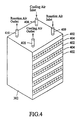
- FIG. 4 is a perspective view of the fuel cell system constructed in accordance with the present invention.
- FIG. 5 is a block diagram of an application of the fuel cell system of the present invention in an electrical vehicle
- FIG. 6 is a block diagram of another application of the fuel cell system of the present invention in an alternating current power generation system.
- FIG. 7 is a block diagram of a further application of the fuel cell system of the present invention in a direct current power generation system.
- a low power fuel cell system in accordance with the present invention comprises a fuel cell stack 302 , which receives hydrogen from a hydrogen storage 310 that may comprise an alloy based hydrogen canisters or pressurized hydrogen canister.
- the supply of the hydrogen from the hydrogen storage 310 to the fuel cell stack 302 is regulated by a flow and pressure regulating device 307 .
- a hydrogen recirculator 318 is connected to the fuel cell stack 302 for recirculation of hydrogen back into the fuel cell stack 302 .
- Air is drawn in by a blower 304 through an air filter 320 . Impurities contained in the air are filtered by the filter 320 . Part of the filtered air is conveyed directly via an air humidifier 316 to the fuel cell stack 302 and is used for reaction, while the other part of the filtered air is conveyed to the fuel cell stack for cooling the fuel cell stack 302 .
- the fuel cell stack 302 includes a plurality of fuel cell units 402 , each of which comprises an anode plate, a cathode plate, a membrane electrode assembly (MEA) and two gas diffusion layers at the two sides of MEA.
- Two adjacent cell units 402 sandwich a cooling plate 404 which comprises a plurality of parallelly arranged air grooves.
- the blower 304 drives the cooling air through a cooling air inlet 406 into the air grooves.
- the cooling air absorbs and carries away the heat in the fuel cell stack 302 and flows out from the cooling air outlet 408 .
- the load of fuel cell stack 302 is increased, a substantial quantity of heat is generated from the electrochemical reaction, and the temperature of the fuel cell stack 302 significantly rises.
- the blower 304 will drive more cooling air into the fuel cell stack 302 to cool down the working temperature. Since the air flow generated by the blower 304 has high pressure and velocity, the heat dissipation effect of the cooling air is excellent. Thereby, the working temperature of the fuel cell stack 302 is effectively reduced, and no other cooling device e.g. a cooling fan is required. Hence, production cost and space are largely saved.
- Humid air from the air humidifier 316 is conveyed into the fuel cell stack 302 via a reaction air inlet 409 and air is conveyed out of the fuel cell stack 302 via a reaction air outlet 410 .
- the air humidifier 316 also receives reaction air from the fuel cell stack 302 , which carries a great amount of moisture since water is continuously and rapidly generated by reaction in the fuel cell stack 302 .
- the fresh air drawn in by the air blower 304 can absorb water from the humid air in the humidifier 316 to provide the outlet air with the desired humidity.
- the air is then fed into the fuel cell stack 302 .
- the moisture contained in the outlet air effectively promotes the reaction in the fuel cell stack 302 .
- the recycle of humid air from the fuel cell stack 302 maintains the fuel cell stack 302 at an appropriate moisture content even at a temperature higher than 40-60° C., and hence the fuel cell stack may work at high performance Therefore, the fuel cell stack 302 is capable of working at heavy load and providing large working current with high performance.
- the supply of hydrogen that is stored in the canister of the hydrogen storage 310 is controlled and regulated by the flow and pressure regulating device 307 which comprises a solenoid valve 306 and a pressure regulating valve 308 .
- the solenoid valve 306 is controlled by a control circuit 324 , such that it is selectively turned on or off for the flowing of the hydrogen from the hydrogen storage 310 , while the pressure regulating valve 308 regulates the pressure of the hydrogen flowing through the solenoid valve 306 to the fuel cell stack 302 .
- the hydrogen recirculator 318 draws unreacted and excessive hydrogen from the fuel cell stack 302 and circulates the hydrogen back into the fuel cell stack 302 . This induces a forced flowing of hydrogen through the fuel cell stack 302 , and subsequently hydrogen is uniformly distributed. Thereby, the reaction between the hydrogen and the oxygen is promoted and the performance of the fuel cell is improved.
- the exhaust valve 314 which may be a solenoid valve, is controlled by the control circuit 324 to remove undesired water and impurities from the fuel cell stack 302 at a regular interval. This maintains the purity of the hydrogen inside the fuel cell stack 302 . Also, accumulation of water inside hydrogen passages of the fuel cell stack 302 can be eliminated in order to maintain the performance of the fuel cell stack 302 .
- the control circuit 324 electrically controls the operation of the flow and pressure regulating device 307 to regulate the hydrogen flowing into the fuel cells stack 302 .
- the control circuit 324 also electrically controls the blower 304 to regulate the air flowing to the air humidifier 316 and the fuel cell stack 302 .
- the control circuit 324 electrically controls the exhaust valve 314 for expelling impurities and water from the fuel cell stack 302 .
- the control circuit 324 may conduct a self-diagnosis, such as detection of the hydrogen pressure of the hydrogen storage 310 , and examination of the operation conditions of the blower 304 , the solenoid valve 306 , the exhaust valve 314 , the fuel cell stack 302 and, if desired, the control circuit 324 itself.
- a backup battery set 325 may be incorporated in the fuel cell system 300 for powering the control circuit 324 in starting up the fuel cell system 300 .
- the backup battery set 325 may comprise a lead-acid battery or the like, which supplies electricity to the control circuit 324 when the fuel cell system 300 is started.
- the power of the backup battery 325 is also supplied to other devices, such as the blower 304 , the solenoid valve 306 and the exhaust valve 314 for the startup operation.
- electricity supplied from the fuel cell stack 302 recharges the backup battery set 325 via a power supplying circuit 326 to maintain future operability of the backup battery set 325 .
- the power supplying circuit 326 converts the DC output voltage from the fuel cell stack 302 into a working voltage for the control circuit 324 and the backup battery set 325 .
- FIG. 5 shows an application of the fuel cell system 300 of the present invention in an electrical vehicle wherein the fuel cell stack 302 of the fuel cell system 300 generates a DC output voltage, which is applied to a driving motor 502 for driving a transmission 504 of the electrical vehicle. It is noted that the components and parts of the fuel cell system 300 of the present invention that is illustrated in FIG. 3 are completely incorporated in FIG. 5 for clarity.
- FIG. 6 shows another application of the fuel cell system 300 of the present invention in an alternating current power generator, which may be portable orstationary.
- the fuel cell stack 302 of the fuel cell system 300 generates a DC output voltage, which is applied to a DC-to-AC converter 602 for converting the DC output voltage generated by the fuel cell stack 302 into an AC output voltage.
- the alternating current outputted from the DC-to-AC converter 602 flows through a voltage regulator 603 for voltage regulation. Frequency of the alternate current so generated may be changed as desired e.g. 60/50 Hz. It is noted that the components and parts of the fuel cell system 300 of the present invention that is illustrated in FIG. 6 are completely incorporated in FIG. 3 for clarity.
- FIG. 7 shows a further application of the fuel cell system 300 of the present invention in a direct current power generator, which may be portable or stationary.
- Thc fuel cell stack 302 of the fuel cell system 300 generates a DC output voltage, which is directly applied to a voltage regulator 603 for voltage regulation. It is noted that the components and parts of the fuel cell system 300 of the present invention that is illustrated in FIG. 7 are completely incorporated in FIG. 3 for clarity.
- the fuel cell system of the present invention provides humidified air containing oxygen to the fuel cell stack for enhancing the reaction and to avoid insufficiency of water in case of heavy loads. It is also noted that the recirculation of the hydrogen back to the fuel cell stack helps promoting electro-chemical reaction inside the fuel cell stack. Part of the air drawn in by the blower is conveyed directly to the fuel cell stack for cooling down of the temperature, and hence no cooling device such as cooling fan is required.
Abstract
Description
- 1. Field of the Invention
- The present invention relates generally to a fuel cell system, and in particularly to a fuel cell system comprising an air cooling device for improving performance thereof.
- 2. Description of the Prior Art
- Fuel cell power system is capable of generating electrical power energy by means of electro-chemical reaction between a fuel, such as hydrogen and methanol, and an oxidizer, such as oxygen. Based on the electrolyte thereof, the fuel cell is classified as proton exchange membrane fuel cell or polymer electrolyte membrane fuel cell, abbreviated as PEMFC or PEM, alkaline fuel cell (AFC), phosphoric acid fuel cell (PAFC), molten carbonate fuel cell (MCFC) and solid oxide fuel cell (SOFC).
- Among these known fuel cells, the PEMFEC is the best-developed technique, having the advantages of low operation temperature, fast start-up and high power density. Thus, the PEMFC is very suitable for transportation vehicles and power generation systems, such as home power systems and other portable and stationary power generation systems.
- Fuel cell of power smaller than 1 kilo-watt usually comprises an air cooling device. FIG. 1 of the attached drawings shows an example of conventional power fuel cell systems comprising a
fuel cell stack 102. Air containing oxygen is drawn in by anair pump 104, and hydrogen stored in ahydrogen canister 110 is conveyed through asolenoid valve 106 and apressure regulator 108 to thefuel cell stack 102. The electrochemical reaction between the hydrogen and oxygen generates electricity with water and heat as byproducts of the reaction. The heat generated subsequently causes the rise of a temperature of thefuel cell stack 102. When the temperature of thefuel cell stack 102 rises too high, acooling fan 112 is driven to turn on for cooling. - FIG. 2 shows a perspective view of a conventional fuel cell comprises a cooling fan. The
fuel cell stack 102 includes a plurality offuel cell units 202, each of which comprises an anode plate, a cathode plate, a membrane electrode assembly (MEA), and two gas diffusion layers at the two sides of MEA. Twoadjacent cell units 202 sandwich acooling plate 204 which comprises a plurality of parallelly arrangedair grooves 206. When thefuel cell stack 102 reaches a high temperature, thecooling fan 112 is driven to turn on and cooling air is drawn into thegrooves 206. The cooling air absorbs and carries away the heat inside thefuel cell stack 102. Subsequently, the temperature offuel cell stack 102 is decreased. - The electro-chemical reaction between hydrogen and oxygen is highly improved in suitable moisturized condition. Accordingly, the temperature of the
fuel cell stack 102 should be maintained at below 40-60° C., otherwise, there may be insufficient water and reaction rate is low. Therefore, when the fuel cell stack reaches a temperature higher than 40-60° C., thecooling fan 112 is driven to turn on for cooling. However, thecooling fan 112 can only generate cooling air of low pressure and velocity, and the cooling effect is poor. Therefore, thefuel cell stack 102 is not capable to work at heavy load and provide large working current. Moreover, an extra space is required for the placement of thecooling fan 112. - Furthermore, to promote the electrochemical reaction between oxygen and hydrogen, a
solenoid valve 106 and apressure regulator 108 control the flowing of hydrogen to thefuel cell stack 102. Such a regulation limits the utility of hydrogen. - It is thus desired to provide a fuel cell system that overcomes the above-discussed disadvantages of the prior art. The present invention provides a fuel cell system with an air cooling device, which enables the fuel cell stack to work at higher temperature while it does not require a cooling fan for cooling.
- Thus, an object of the present invention is to provide a fuel cell power system which comprises a fuel cell stack, an air humidifier, a blower, a hydrogen storage, a flow and pressure regulator, a hydrogen recirculator and a control circuit. The air humidifier humidifies the air supplied to the fuel cell stack with the humidity from the fuel cell stack, the blower drives the air containing oxygen to the air humidifier and fuel cell stack, the hydrogen storage stores and supplies hydrogen to the fuel cell stack, a flow and pressure regulating device regulates the hydrogen flow, the hydrogen recirculator receives excessive hydrogen from the fuel cell stack and circulates the hydrogen back into the fuel cell stack, and the control circuit electrically controls the flow and pressure regulating device and the blower.
- To achieve the above objects, in accordance with the present invention, there is provided a fuel cell system which is capable of humidifying and supplying the air to fuel cell stack, so that even when the working temperature rises, there is sufficient moisture in the fuel cell stack for performing electro-chemical reaction at high rate. It enables the fuel cell stack to work at heavy load and provide large working current. Moreover, the fuel cell stack does not require a cooling fan for cooling, and production cost and space are greatly saved. Furthermore, unreacted and excessive hydrogen is recirculated to the fuel cell system. By this means, the utility of hydrogen is highly enhanced.
- The present invention will be apparent to those skilled in the art by reading the following description of a number of preferred embodiments thereof, with reference to the attached drawings, in which:
- FIG. 1 is a system block diagram of a conventional fuel cell system;
- FIG. 2 is a perspective view of a conventional fuel cell system comprising a cooling fan;
- FIG. 3 is a system block diagram of a fuel cell system constructed in accordance with the present invention;
- FIG. 4 is a perspective view of the fuel cell system constructed in accordance with the present invention;
- FIG. 5 is a block diagram of an application of the fuel cell system of the present invention in an electrical vehicle;
- FIG. 6 is a block diagram of another application of the fuel cell system of the present invention in an alternating current power generation system; and
- FIG. 7 is a block diagram of a further application of the fuel cell system of the present invention in a direct current power generation system.
- With reference to the drawings and in particular to FIG. 3, a low power fuel cell system in accordance with the present invention, generally designated with
reference numeral 300, comprises afuel cell stack 302, which receives hydrogen from ahydrogen storage 310 that may comprise an alloy based hydrogen canisters or pressurized hydrogen canister. The supply of the hydrogen from thehydrogen storage 310 to thefuel cell stack 302 is regulated by a flow andpressure regulating device 307. Also, ahydrogen recirculator 318 is connected to thefuel cell stack 302 for recirculation of hydrogen back into thefuel cell stack 302. - Air is drawn in by a
blower 304 through anair filter 320. Impurities contained in the air are filtered by thefilter 320. Part of the filtered air is conveyed directly via anair humidifier 316 to thefuel cell stack 302 and is used for reaction, while the other part of the filtered air is conveyed to the fuel cell stack for cooling thefuel cell stack 302. - As shown in FIG. 4, the
fuel cell stack 302 includes a plurality offuel cell units 402, each of which comprises an anode plate, a cathode plate, a membrane electrode assembly (MEA) and two gas diffusion layers at the two sides of MEA. Twoadjacent cell units 402 sandwich acooling plate 404 which comprises a plurality of parallelly arranged air grooves. Theblower 304 drives the cooling air through acooling air inlet 406 into the air grooves. The cooling air absorbs and carries away the heat in thefuel cell stack 302 and flows out from thecooling air outlet 408. When the load offuel cell stack 302 is increased, a substantial quantity of heat is generated from the electrochemical reaction, and the temperature of thefuel cell stack 302 significantly rises. In this situation, theblower 304 will drive more cooling air into thefuel cell stack 302 to cool down the working temperature. Since the air flow generated by theblower 304 has high pressure and velocity, the heat dissipation effect of the cooling air is excellent. Thereby, the working temperature of thefuel cell stack 302 is effectively reduced, and no other cooling device e.g. a cooling fan is required. Hence, production cost and space are largely saved. Humid air from theair humidifier 316 is conveyed into thefuel cell stack 302 via areaction air inlet 409 and air is conveyed out of thefuel cell stack 302 via areaction air outlet 410. - The
air humidifier 316 also receives reaction air from thefuel cell stack 302, which carries a great amount of moisture since water is continuously and rapidly generated by reaction in thefuel cell stack 302. The fresh air drawn in by theair blower 304 can absorb water from the humid air in thehumidifier 316 to provide the outlet air with the desired humidity. The air is then fed into thefuel cell stack 302. The moisture contained in the outlet air effectively promotes the reaction in thefuel cell stack 302. Moreover, the recycle of humid air from thefuel cell stack 302 maintains thefuel cell stack 302 at an appropriate moisture content even at a temperature higher than 40-60° C., and hence the fuel cell stack may work at high performance Therefore, thefuel cell stack 302 is capable of working at heavy load and providing large working current with high performance. - The supply of hydrogen that is stored in the canister of the
hydrogen storage 310 is controlled and regulated by the flow andpressure regulating device 307 which comprises asolenoid valve 306 and apressure regulating valve 308. Thesolenoid valve 306 is controlled by acontrol circuit 324, such that it is selectively turned on or off for the flowing of the hydrogen from thehydrogen storage 310, while thepressure regulating valve 308 regulates the pressure of the hydrogen flowing through thesolenoid valve 306 to thefuel cell stack 302. - The hydrogen recirculator 318 draws unreacted and excessive hydrogen from the
fuel cell stack 302 and circulates the hydrogen back into thefuel cell stack 302. This induces a forced flowing of hydrogen through thefuel cell stack 302, and subsequently hydrogen is uniformly distributed. Thereby, the reaction between the hydrogen and the oxygen is promoted and the performance of the fuel cell is improved. - The
exhaust valve 314, which may be a solenoid valve, is controlled by thecontrol circuit 324 to remove undesired water and impurities from thefuel cell stack 302 at a regular interval. This maintains the purity of the hydrogen inside thefuel cell stack 302. Also, accumulation of water inside hydrogen passages of thefuel cell stack 302 can be eliminated in order to maintain the performance of thefuel cell stack 302. - The
control circuit 324 electrically controls the operation of the flow andpressure regulating device 307 to regulate the hydrogen flowing into the fuel cells stack 302. Thecontrol circuit 324 also electrically controls theblower 304 to regulate the air flowing to theair humidifier 316 and thefuel cell stack 302. Thecontrol circuit 324 electrically controls theexhaust valve 314 for expelling impurities and water from thefuel cell stack 302. In addition, thecontrol circuit 324 may conduct a self-diagnosis, such as detection of the hydrogen pressure of thehydrogen storage 310, and examination of the operation conditions of theblower 304, thesolenoid valve 306, theexhaust valve 314, thefuel cell stack 302 and, if desired, thecontrol circuit 324 itself. - A backup battery set 325 may be incorporated in the
fuel cell system 300 for powering thecontrol circuit 324 in starting up thefuel cell system 300. The backup battery set 325 may comprise a lead-acid battery or the like, which supplies electricity to thecontrol circuit 324 when thefuel cell system 300 is started. The power of thebackup battery 325 is also supplied to other devices, such as theblower 304, thesolenoid valve 306 and theexhaust valve 314 for the startup operation. Once thefuel cell system 300 is properly started, electricity supplied from thefuel cell stack 302 recharges the backup battery set 325 via apower supplying circuit 326 to maintain future operability of thebackup battery set 325. Thepower supplying circuit 326 converts the DC output voltage from thefuel cell stack 302 into a working voltage for thecontrol circuit 324 and thebackup battery set 325. - Fuel cell power system of power smaller than 1 kilo-watt is simple in structure and inexpensive. It is usually applied in applications requiring low power, such as electrical vehicles and low power generators. FIG. 5 shows an application of the
fuel cell system 300 of the present invention in an electrical vehicle wherein thefuel cell stack 302 of thefuel cell system 300 generates a DC output voltage, which is applied to a drivingmotor 502 for driving atransmission 504 of the electrical vehicle. It is noted that the components and parts of thefuel cell system 300 of the present invention that is illustrated in FIG. 3 are completely incorporated in FIG. 5 for clarity. - FIG. 6 shows another application of the
fuel cell system 300 of the present invention in an alternating current power generator, which may be portable orstationary. Thefuel cell stack 302 of thefuel cell system 300 generates a DC output voltage, which is applied to a DC-to-AC converter 602 for converting the DC output voltage generated by thefuel cell stack 302 into an AC output voltage. The alternating current outputted from the DC-to-AC converter 602 flows through avoltage regulator 603 for voltage regulation. Frequency of the alternate current so generated may be changed as desired e.g. 60/50 Hz. It is noted that the components and parts of thefuel cell system 300 of the present invention that is illustrated in FIG. 6 are completely incorporated in FIG. 3 for clarity. - FIG. 7 shows a further application of the
fuel cell system 300 of the present invention in a direct current power generator, which may be portable or stationary. Thcfuel cell stack 302 of thefuel cell system 300 generates a DC output voltage, which is directly applied to avoltage regulator 603 for voltage regulation. It is noted that the components and parts of thefuel cell system 300 of the present invention that is illustrated in FIG. 7 are completely incorporated in FIG. 3 for clarity. - To this point, it can be noted that the fuel cell system of the present invention provides humidified air containing oxygen to the fuel cell stack for enhancing the reaction and to avoid insufficiency of water in case of heavy loads. It is also noted that the recirculation of the hydrogen back to the fuel cell stack helps promoting electro-chemical reaction inside the fuel cell stack. Part of the air drawn in by the blower is conveyed directly to the fuel cell stack for cooling down of the temperature, and hence no cooling device such as cooling fan is required.
- Although the present invention has been described with reference to the preferred embodiments thereof, it is apparent to those skilled in the art that a variety of modifications and changes may be made without departing from the scope of the present invention which is intended to be defined by the appended claims.
Claims (11)
Applications Claiming Priority (2)
| Application Number | Priority Date | Filing Date | Title |
|---|---|---|---|
| TW091107939A TW548872B (en) | 2002-04-18 | 2002-04-18 | Small-power air-cooling type fuel cell |
| TW91107939 | 2002-04-18 |
Publications (2)
| Publication Number | Publication Date |
|---|---|
| US20030198848A1 true US20030198848A1 (en) | 2003-10-23 |
| US7008710B2 US7008710B2 (en) | 2006-03-07 |
Family
ID=29213279
Family Applications (1)
| Application Number | Title | Priority Date | Filing Date |
|---|---|---|---|
| US10/414,090 Expired - Lifetime US7008710B2 (en) | 2002-04-18 | 2003-04-16 | Fuel cell system with air cooling device |
Country Status (3)
| Country | Link |
|---|---|
| US (1) | US7008710B2 (en) |
| JP (1) | JP2003317760A (en) |
| TW (1) | TW548872B (en) |
Cited By (7)
| Publication number | Priority date | Publication date | Assignee | Title |
|---|---|---|---|---|
| US20060194086A1 (en) * | 2005-02-25 | 2006-08-31 | Kuai-Teng Hsu | Inverse recycle power system |
| US20070111066A1 (en) * | 2005-11-17 | 2007-05-17 | Airbus Deutschland Gmbh | Aeroplane Steam-Bath Facility |
| CN1333484C (en) * | 2005-12-31 | 2007-08-22 | 清华大学 | Normal pressure fuel battery air humidifying system |
| EP1892493A1 (en) * | 2006-08-21 | 2008-02-27 | LG Electronics Inc. | Fuel cell system |
| US20090208801A1 (en) * | 2006-05-05 | 2009-08-20 | Yang Jefferson Ys | Fuel cell system with discharged water treatment facilities |
| US20090325012A1 (en) * | 2004-12-17 | 2009-12-31 | Astris Energi Inc. | Alkaline fuel cell system |
| CN111211338A (en) * | 2020-03-19 | 2020-05-29 | 吉林大学 | High-pressure proton exchange membrane fuel cell power system |
Families Citing this family (9)
| Publication number | Priority date | Publication date | Assignee | Title |
|---|---|---|---|---|
| AU2003304609A1 (en) * | 2003-12-12 | 2005-06-29 | Lg Electronics Inc. | Fuel cell system and control method thereof |
| JP4448703B2 (en) * | 2004-01-30 | 2010-04-14 | 本田技研工業株式会社 | In-vehicle fuel cell stack operation method |
| JP4371308B2 (en) * | 2004-01-30 | 2009-11-25 | 本田技研工業株式会社 | Automotive fuel cell stack |
| JP4482341B2 (en) * | 2004-01-30 | 2010-06-16 | 本田技研工業株式会社 | In-vehicle fuel cell stack operation method |
| JP2008146883A (en) * | 2006-12-06 | 2008-06-26 | Canon Inc | Fuel cell apparatus |
| KR101417269B1 (en) * | 2012-05-07 | 2014-07-08 | 기아자동차주식회사 | Manifold block integrated with hydrogen supply system for fuel cell |
| TWI486269B (en) * | 2012-06-01 | 2015-06-01 | Automotive Res & Testing Ct | Thermal management device and method for electric vehicle vehicle system |
| TWI642566B (en) * | 2017-11-13 | 2018-12-01 | 中華汽車工業股份有限公司 | Car motor with built-in charge control function |
| JP7459840B2 (en) | 2021-06-02 | 2024-04-02 | トヨタ自動車株式会社 | Air-cooled fuel cell system |
Citations (6)
| Publication number | Priority date | Publication date | Assignee | Title |
|---|---|---|---|---|
| US5059494A (en) * | 1990-05-10 | 1991-10-22 | International Fuel Cells | Fuel cell power plant |
| US5082752A (en) * | 1989-11-25 | 1992-01-21 | Ishikawajima-Harima Heavy Industries Co., Ltd. | Power generation system using molten carbonate fuel cell |
| US5084363A (en) * | 1990-01-10 | 1992-01-28 | International Fuel Cells Corp. | Molten carbonate fuel cell power plant |
| US6500573B1 (en) * | 1998-09-07 | 2002-12-31 | Kabushiki Kaisha Toyota Chuo Kenkyusho | Humidifer device for fuel cells and operating system thereof |
| US20030203258A1 (en) * | 2002-04-24 | 2003-10-30 | Yang Jefferson Ys | Fuel cell system with liquid cooling device |
| US6663900B2 (en) * | 2002-02-01 | 2003-12-16 | Kemin Foods, Lc | Microcapsules having high carotenoid content |
Family Cites Families (10)
| Publication number | Priority date | Publication date | Assignee | Title |
|---|---|---|---|---|
| JPH0547396A (en) * | 1991-08-19 | 1993-02-26 | Nippon Telegr & Teleph Corp <Ntt> | Fuel cell power generating system |
| JPH0765851A (en) * | 1993-08-24 | 1995-03-10 | Tokyo Gas Co Ltd | Dc output fuel cell system and its operation |
| JPH09213353A (en) * | 1996-02-05 | 1997-08-15 | Shikoku Sogo Kenkyusho:Kk | Fuel cell generating apparatus |
| JP4346704B2 (en) * | 1998-03-31 | 2009-10-21 | マツダ株式会社 | Fuel cell system |
| JP4427833B2 (en) * | 1999-02-23 | 2010-03-10 | マツダ株式会社 | Fuel cell device |
| JP3530413B2 (en) * | 1999-03-25 | 2004-05-24 | 三洋電機株式会社 | Fuel cell power generation system and operation method thereof |
| JP4042273B2 (en) * | 1999-10-20 | 2008-02-06 | トヨタ自動車株式会社 | Fuel cell vehicle |
| JP2002008691A (en) * | 2000-06-16 | 2002-01-11 | Denso Corp | Fuel cell system |
| JP2001266907A (en) * | 2000-03-22 | 2001-09-28 | Matsushita Seiko Co Ltd | Fan heater |
| JP2002008698A (en) * | 2000-06-26 | 2002-01-11 | Toshiba Corp | Fuel cell generating device |
-
2002
- 2002-04-18 TW TW091107939A patent/TW548872B/en not_active IP Right Cessation
-
2003
- 2003-04-15 JP JP2003110491A patent/JP2003317760A/en active Pending
- 2003-04-16 US US10/414,090 patent/US7008710B2/en not_active Expired - Lifetime
Patent Citations (6)
| Publication number | Priority date | Publication date | Assignee | Title |
|---|---|---|---|---|
| US5082752A (en) * | 1989-11-25 | 1992-01-21 | Ishikawajima-Harima Heavy Industries Co., Ltd. | Power generation system using molten carbonate fuel cell |
| US5084363A (en) * | 1990-01-10 | 1992-01-28 | International Fuel Cells Corp. | Molten carbonate fuel cell power plant |
| US5059494A (en) * | 1990-05-10 | 1991-10-22 | International Fuel Cells | Fuel cell power plant |
| US6500573B1 (en) * | 1998-09-07 | 2002-12-31 | Kabushiki Kaisha Toyota Chuo Kenkyusho | Humidifer device for fuel cells and operating system thereof |
| US6663900B2 (en) * | 2002-02-01 | 2003-12-16 | Kemin Foods, Lc | Microcapsules having high carotenoid content |
| US20030203258A1 (en) * | 2002-04-24 | 2003-10-30 | Yang Jefferson Ys | Fuel cell system with liquid cooling device |
Cited By (7)
| Publication number | Priority date | Publication date | Assignee | Title |
|---|---|---|---|---|
| US20090325012A1 (en) * | 2004-12-17 | 2009-12-31 | Astris Energi Inc. | Alkaline fuel cell system |
| US20060194086A1 (en) * | 2005-02-25 | 2006-08-31 | Kuai-Teng Hsu | Inverse recycle power system |
| US20070111066A1 (en) * | 2005-11-17 | 2007-05-17 | Airbus Deutschland Gmbh | Aeroplane Steam-Bath Facility |
| CN1333484C (en) * | 2005-12-31 | 2007-08-22 | 清华大学 | Normal pressure fuel battery air humidifying system |
| US20090208801A1 (en) * | 2006-05-05 | 2009-08-20 | Yang Jefferson Ys | Fuel cell system with discharged water treatment facilities |
| EP1892493A1 (en) * | 2006-08-21 | 2008-02-27 | LG Electronics Inc. | Fuel cell system |
| CN111211338A (en) * | 2020-03-19 | 2020-05-29 | 吉林大学 | High-pressure proton exchange membrane fuel cell power system |
Also Published As
| Publication number | Publication date |
|---|---|
| TW548872B (en) | 2003-08-21 |
| JP2003317760A (en) | 2003-11-07 |
| US7008710B2 (en) | 2006-03-07 |
Similar Documents
| Publication | Publication Date | Title |
|---|---|---|
| US20030203258A1 (en) | Fuel cell system with liquid cooling device | |
| US7008710B2 (en) | Fuel cell system with air cooling device | |
| US6534210B2 (en) | Auxiliary convective fuel cell stacks for fuel cell power generation systems | |
| EP1465281A2 (en) | Fuel cell system with liquid cooling device | |
| US6558827B1 (en) | High fuel utilization in a fuel cell | |
| CA2436883C (en) | Fuel cell system with air cooling device | |
| JP2005259692A (en) | Method of starting fuel cell system by using environmental air and low-voltage blower | |
| US20050266280A1 (en) | Electronic apparatus system, fuel cell unit and power supply control method | |
| US7816884B2 (en) | Fuel cell system and method of starting operation of fuel cell system having an energy storage by reducing an amount of electrical energy in the energy storage prior to starting power generation | |
| US7267900B2 (en) | Fuel cell system | |
| JP3872791B2 (en) | Intermittent cooling of fuel cells | |
| US6696190B2 (en) | Fuel cell system and method | |
| US7588844B2 (en) | Method of starting up operation of fuel cell at low temperature | |
| JP2007059303A (en) | Fuel cell system, fuel cell power generator, and its operation method | |
| JP2004327360A (en) | Fuel cell system | |
| JP2007141744A (en) | Fuel cell system | |
| JPH11176454A (en) | Power source for fuel cell accessory | |
| US7479335B2 (en) | Anode humidification | |
| JP3583914B2 (en) | Auxiliary power supply for fuel cell | |
| KR101223555B1 (en) | Fuel cell system and driving method for the same | |
| JP2003331892A (en) | Fuel cell system, and starting method of fuel cell system | |
| JP2003331891A (en) | Fuel cell system, and starting method of fuel cell system | |
| JP2007250216A (en) | Fuel cell system and method of operating same | |
| KR101084078B1 (en) | Fuel cell system and driving method the same | |
| JP2021182512A (en) | Fuel cell system |
Legal Events
| Date | Code | Title | Description |
|---|---|---|---|
| AS | Assignment |
Owner name: ASIA PACIFIC FUEL CELL TECHNOLOGIES, LTD., TAIWAN Free format text: ASSIGNMENT OF ASSIGNORS INTEREST;ASSIGNORS:YANG, JEFFERSON YS;HSU, YAO-SHENG;REEL/FRAME:013977/0480 Effective date: 20030313 |
|
| STCF | Information on status: patent grant |
Free format text: PATENTED CASE |
|
| FPAY | Fee payment |
Year of fee payment: 4 |
|
| REFU | Refund |
Free format text: REFUND - PAYMENT OF MAINTENANCE FEE, 8TH YR, SMALL ENTITY (ORIGINAL EVENT CODE: R2552); ENTITY STATUS OF PATENT OWNER: SMALL ENTITY |
|
| FPAY | Fee payment |
Year of fee payment: 8 |
|
| FPAY | Fee payment |
Year of fee payment: 12 |