US20040059185A1 - Valve for bladder control device - Google Patents
Valve for bladder control device Download PDFInfo
- Publication number
- US20040059185A1 US20040059185A1 US10/666,044 US66604403A US2004059185A1 US 20040059185 A1 US20040059185 A1 US 20040059185A1 US 66604403 A US66604403 A US 66604403A US 2004059185 A1 US2004059185 A1 US 2004059185A1
- Authority
- US
- United States
- Prior art keywords
- stopper
- valve
- lumen
- diameter
- accordance
- Prior art date
- Legal status (The legal status is an assumption and is not a legal conclusion. Google has not performed a legal analysis and makes no representation as to the accuracy of the status listed.)
- Granted
Links
Images


Classifications
-
- A—HUMAN NECESSITIES
- A61—MEDICAL OR VETERINARY SCIENCE; HYGIENE
- A61F—FILTERS IMPLANTABLE INTO BLOOD VESSELS; PROSTHESES; DEVICES PROVIDING PATENCY TO, OR PREVENTING COLLAPSING OF, TUBULAR STRUCTURES OF THE BODY, e.g. STENTS; ORTHOPAEDIC, NURSING OR CONTRACEPTIVE DEVICES; FOMENTATION; TREATMENT OR PROTECTION OF EYES OR EARS; BANDAGES, DRESSINGS OR ABSORBENT PADS; FIRST-AID KITS
- A61F2/00—Filters implantable into blood vessels; Prostheses, i.e. artificial substitutes or replacements for parts of the body; Appliances for connecting them with the body; Devices providing patency to, or preventing collapsing of, tubular structures of the body, e.g. stents
- A61F2/0004—Closure means for urethra or rectum, i.e. anti-incontinence devices or support slings against pelvic prolapse
- A61F2/0022—Closure means for urethra or rectum, i.e. anti-incontinence devices or support slings against pelvic prolapse placed deep in the body opening
Landscapes
- Health & Medical Sciences (AREA)
- Vascular Medicine (AREA)
- Life Sciences & Earth Sciences (AREA)
- Oral & Maxillofacial Surgery (AREA)
- Transplantation (AREA)
- Engineering & Computer Science (AREA)
- Biomedical Technology (AREA)
- Cardiology (AREA)
- Urology & Nephrology (AREA)
- Heart & Thoracic Surgery (AREA)
- Animal Behavior & Ethology (AREA)
- General Health & Medical Sciences (AREA)
- Public Health (AREA)
- Veterinary Medicine (AREA)
- Prostheses (AREA)
- Infusion, Injection, And Reservoir Apparatuses (AREA)
Abstract
A valve for a bladder control device including an elongate housing having a valve seat disposed therein. A stopper is also disposed within the housing and is moveable between a first position in which the stopper engages the valve seat and a second position wherein the stopper is moved distally of the valve seat. A tension spring can be connected to the stopper to biases the stopper toward the valve seat. A lumen is defined through the housing having a first portion disposed distally of the valve seat having a diameter approximately equal to a diameter of the stopper. A second portion of the lumen disposed distally of the first portion has a greater diameter than the first portion of the lumen. Yet a third portion of the lumen disposed distally of the second portion has a diameter less than that of the first portion.
Description
- The present invention relates generally to the field of bladder control devices. More particularly, the invention relates to the field of bladder control devices in which a valve is provided to control flow from the bladder of a patient.
- Bladder control devices related to the field of this invention include devices such as those disclosed by Kulisz et al., in U.S. Pat. No. 5,512,032 and U.S. Pat. No. 5,701,916. The former patent discloses a bladder control device including a valve which remains open under the influence of flow through the device in accordance with Bernoulli's Principle. The latter patent discloses proximally and distally disposed retainers for retaining the bladder control device within a patient's urethra. These pioneering devices can be activated in an intuitive way by a patient, simply by the patient increasing bladder pressure. The valve remains open at a lower pressure so long as a certain minimal flow rate through the valve continues. When the flow subsides, the valve closes.
- Intraurethral bladder control devices are disposed within the urethra during use. Consequently, patients and their physicians desire that the diameter of the device be limited without compromising the performance of the device. It can be appreciated that larger diameter bladder control devices could cause some discomfort during insertion and use. Scaling down a device, i.e., making a smaller device having the same configuration, will reduce the flow through the device exponentially. Reducing flow through the valve limits the force creatable by the Bernoulli's Principle to hold the valve open. Additionally, if the diameter of a compression spring, as used in the prior devices to bias the valve close, is scaled down, the spring is subject to buckling, which could leave the valve in a permanently open position.
- The present invention pertains to a valve for a bladder control device which incorporates features allowing the device to be effective when produced in small diameters, such as 18F, for example. The valve for a bladder control device in accordance with the present invention includes an elongate housing which has a proximal end and a distal end. A lumen extends through the housing. A valve seat is disposed within the housing and a stopper is disposed within the housing. The stopper is moveable between a first position engaging the valve seat and a second position disposed distally of the valve seat. In the first position, the valve is closed, in the second position the valve is at least partially open.
- The valve in accordance with the present invention, preferably includes a tension spring connected to a stopper to bias the stopper toward the valve seat. The spring is under greater tension loading when the stopper is in the second position that when the stopper is in the first position. The spring can include an elongate shaft portion having a proximal end and a distal end. The proximal end of the shaft portion is preferably connected to the stopper and the distal end of the shaft portion is preferably connected to a helical portion of the spring.
- The stopper can include a proximal portion having a first diameter generally sized to engage the valve seat. The stopper preferably has a distal portion having a diameter greater than the diameter of the proximal portion.
- The lumen through the housing can include a portion disposed distally of the valve seat having a diameter approximately equal to the diameter of the distal portion of the stopper. The stopper is preferably slidably disposed within this portion of the lumen for movement between the first and second positions. A second portion of the lumen, disposed distally of the first portion of the lumen, has a diameter greater than the diameter of the first portion of the lumen. The lumen also preferably includes a third portion disposed distally of the second portion of the lumen which has a diameter less than the diameter of the second portion of the lumen. This region of the lumen, in conjunction with the larger diameter distal portion of the stopper, can induce the desired force in accordance with Bernoulli's Principle to retain the stopper in the second position so long as a certain minimum flow rate through the lumen is maintained.
- The housing in the valve of the present invention preferably has an outer diameter of between about 16F to 22F, and more preferably, about 18F. It can be appreciated, however, that valves having greater or lesser outside diameters may also be made in accordance with the present invention.
- FIG. 1 is a cross sectional view of a valve in accordance with the present invention wherein the stopper is shown in engagement with a valve seat;
- FIG. 2 is a cross sectional view of the valve of FIG. 1, wherein the stopper is moved distally away from the valve seat; and
- FIG. 3 is a view of the valve of FIG. 2, wherein the stopper is moved yet further distally to open the valve.
- Referring now to the drawings wherein like reference numerals refer to like elements throughout the several views, FIG. 1 is a schematic cross sectional view of a
valve 10 for a bladder control device in accordance with the present invention.Housing 12 can be formed from a biocompatible polymer, metal or other material.Housing 12 can be formed from a single piece or from an assembly of several pieces. - Valve 10 includes an
elongate housing 12 having alumen 14 extending therethrough from aproximal end 16 to adistal end 18. Valve 10 can be placed in the urethra of a patient. It can be retained within the urethra by proximal and distal retainers such as those disclosed in U.S. Pat. No. 5,701,916 to Kulisz et al. which is incorporated herein by reference. It should be understood, however, that the use of this valve is not limited to a configuration including the proximal and distal retainers of the referenced U.S. patent. It is contemplated that the valve could be used for bladder control of both male and female incontinence. - A
valve seat 20 is disposed withinhousing 12.Valve seat 20 can be a narrow or constricted diameter region of thelumen 14. The diameter ofseat 20 is D1 (Radius, R1=D1/2). Distally ofvalve seat 20 is afirst lumen portion 22 having a diameter D (Radius, R3=D3/2).Lumen 14 includes asecond lumen portion 24, disposed distally offirst lumen portion 22, which has a diameter D4 (Radius, R4=D4/2). Diameter D4 is greater than diameter D3. Lumen 14 also includes athird lumen portion 26 disposed distally ofsecond lumen portion 24.Third lumen portion 26 has a diameter D5 which is less than diameter D4. Lumen 14 tapers along aslope 28 betweensecond lumen portion 24 andthird lumen portion 26. - Disposed within
housing 12 is astopper 30.Stopper 30 preferably has aproximal portion 31 configured for engagement withvalve seat 20.Proximal portion 31 has a diameter of D1. Disposed distally ofproximal portion 31 is aportion 32 having a diameter D2 (Radius, R2=R2/2) less than D3 offirst lumen portion 22. Yet more proximally,stopper 30 includes aplunger portion 34 having a diameter approximately equal to, but less than D3 offirst lumen portion 22.Stopper 30 includes a slopingportion 35 sloping fromplunger portion 34 to the distal end ofstopper 30.Stopper 30 can be from a polymer, metal or other biocompatible material. - Disposed within
housing 10 is aspring 36 for biasingstopper 30 towardvalve seat 20.Spring 36 is preferably disposed distally ofvalve seat 28.Spring 36 is preferably a tension spring include anelongate shaft portion 40 having a proximal end connected tostopper 30 and a distal end connected to ahelical spring portion 38. The opposite end ofspring portion 38, not connected toshaft 40, can be affixed tohousing 12 at, for example, acircumferential stop 42.Spring 40 can be made from stainless steel, NiTi alloy or other biocompatible material and suitable for the intended use. - A preferred relationship between R 1, R2, R3, and R4 can be determined solving three equations. Assuming that R4, the maximum inner diameter of
lumen 14, is a given and that ΔR=R=R2−R1, then R1, R2 and R3 can be found using the following formulas: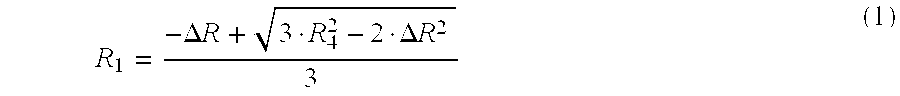
- R 3={square root}{square root over (R 1 2 +R 2 2)} (3)
- The formulas given are preferred formulas, but can be viewed as exemplary. The length of
first lumen portion 22 is preferably long enough thatstopper 30 can move somewhat longitudinally therethrough without allowing flow throughlumen 14. This could dampen spikes in bladder pressure without openingvalve 10. This is an optional feature which is viewed as desirable. -
Housing 12 preferably has an outer diameter of 14F to 26F, and more preferably between 16F and 22F, and most preferably, about 18F. It can be appreciated that the valve described herein could also be scaled upward in size for other uses in addition to placement in the urethra. The configuration ofvalve 10 allowing for the production of relatively high flow rate valves disposed in housings having small outside diameters. - FIG. 1 shows
stopper 30 in a first position A in whichproximal portion 31 is in engagement withvalve seat 20. FIG. 2 is a view ofvalve 10 of FIG. 1 in whichstopper 30 is shown in a second position B. In position B, the pressure at the proximal end ofvalve 10 has increased enough to movestopper 30 away fromvalve seat 20.Stopper 30 is still, however, disposed withinfirst lumen portion 22. Thedistal diameter portion 34 ofstopper 30 engages the luminal wall ofportion 22. Thus, there is still no flow throughlumen 14, as is the case whenstopper 30 is in engagement withseat 20. - FIG. 3 is a view of
valve 10 of FIGS. 1 and 2. In FIG. 3,stopper 30 is disposed in yet another second position C. In position C,portion 34 ofstopper 30 is disposed withinsecond lumen portion 24. Diameter D4 oflumen portion 24 is sufficiently large to allow flow aroundplunger portion 34 ofstopper 30, as shown by the arrows inlumen 14. In position C, the flow betweenslope 28 oflumen portion 24 and slopingportion 35 ofstopper 30 can create a negative pressure in accordance with Bernoulli Principle. The negative pressure tends to drawstopper 30 in a distal direction. Once the flow subsides, however, the force generated in accordance with the Bernoulli Principle will cease andstopper 30 will move proximally towardvalve seat 20. If the pressure in the proximal portion oflumen 14 is sufficiently low,stopper 30 will return to position A. - As can be seen in FIGS. 1, 2 and 3 as
stopper 30 moves from position A to B and then to C,helical spring portion 38 elongates in a distal direction. Thus, rather than compressingportion 38,spring portion 38 is elongated under tension loading. - Numerous characteristics and advantages of the invention covered by this document have been set forth in the foregoing description. It will be understood, however, that this disclosure is, in many respects, only illustrative. Changes may be made in details, particularly in matters of shape, size and ordering of steps without exceeding the scope of the invention. The invention's scope is, of course, defined in the language in which the appended claims are expressed.
Claims (19)
1. A valve for a bladder control device, comprising:
an elongate housing having a proximal end and a distal end, and a lumen extending therethrough;
a valve seat disposed within the housing;
a stopper disposed within the housing and moveable between a first position engaging the valve seat and a second position disposed distally of the valve seat; and
a tension spring connected to the stopper disposed to biases the stopper toward the valve seat, the spring being under greater tension loading when the stopper is in the second position than when the stopper is in the first position.
2. The valve in accordance with claim 1 , wherein the spring includes a helical portion.
3. The valve in accordance with claim 1 , wherein the spring is disposed distally of the stopper.
4. The valve in accordance with claim 3 , wherein the spring includes an elongate shaft portion, having a proximal end and a distal end, the proximal end of the shaft portion being connected to the stopper, and the distal end of the shaft portion being connected to a helical portion.
5. The valve in accordance with claim 1 , wherein the stopper includes a proximal portion having a first diameter.
6. The valve in accordance with claim 5 , wherein the stopper includes a distal portion having a second diameter greater than the first diameter.
7. The valve in accordance with claim 6 , wherein a first portion of the lumen disposed distally of the valve seat has a diameter approximately equal to the second diameter of the stopper and the stopper is slidably disposed therein for movement between the first and second positions.
8. The valve in accordance with claim 7 , wherein a second portion of the lumen disposed distally of the first portion of the lumen has a diameter greater than the diameter of the first portion of the lumen.
9. The device in accordance with claim 8 , wherein a third portion of the lumen disposed distally of the second portion of the lumen has a diameter less than the diameter of the second portion of the lumen.
10. The valve in accordance with claim 1 , wherein the housing has an outer diameter of between 16F to 22F.
11. The valve in accordance with claim 10 , wherein the outside diameter of the housing is approximately 18F.
12. A valve for a bladder control device, comprising:
an elongate housing having a proximal end, a distal end, and a lumen extending therethrough;
a valve seat disposed within the housing;
a stopper disposed within the housing and moveable between a first position engaging the valve seat and a second position disposed distally of the valve seat, the stopper includes a proximal portion having a first diameter and a distal portion having a second diameter greater than the first diameter;
a spring connected to the stopper to bias the stopper toward the valve seat; and
wherein a first portion of the lumen is disposed distally of the valve seat and has a diameter approximately equal to the second diameter of the stopper, and the stopper is slidably disposed in the first portion of the lumen for movement between the first and second positions, and a second portion of the lumen, having a diameter greater than the diameter of the first portion of the lumen, is disposed distally of the first portion of the lumen.
13. The valve in accordance with claim 12 , wherein the spring comprises a tension spring being under greater tension loading when the stopper is in the second position than when the stopper is in the first position.
14. The valve in accordance with claim 12 , wherein the spring includes a helical portion.
15. The valve in accordance with claim 12 , wherein the spring is disposed distally of the stopper.
16. The valve in accordance with claim 15 , wherein the spring includes an elongate shaft portion including a proximal end and a distal end, the proximal end of the shaft portion is connected to the stopper and the distal end of the shaft portion is connected to the helical portion.
17. The valve in accordance with claim 12 , wherein a third portion of the lumen, disposed distally of the second portion of the lumen, has a diameter greater than the diameter of the second portion of the lumen.
18. The valve in accordance with claim 12 , wherein the housing has an outer diameter between about 16F to 22F.
19. The valve in accordance with claim 18 , wherein the outside diameter of the housing is approximately 18F.
Priority Applications (3)
| Application Number | Priority Date | Filing Date | Title |
|---|---|---|---|
| US10/666,044 US6926665B2 (en) | 1998-12-09 | 2003-09-19 | Valve for bladder control device |
| US11/175,611 US7087009B2 (en) | 1998-12-09 | 2005-07-06 | Valve for bladder control device |
| US11/426,498 US20060241338A1 (en) | 1998-12-09 | 2006-06-26 | Valve for bladder control device |
Applications Claiming Priority (3)
| Application Number | Priority Date | Filing Date | Title |
|---|---|---|---|
| US09/207,821 US6183413B1 (en) | 1998-12-09 | 1998-12-09 | Valve for bladder control device |
| US09/777,060 US6652448B2 (en) | 1998-12-09 | 2001-02-05 | Valve for bladder control device |
| US10/666,044 US6926665B2 (en) | 1998-12-09 | 2003-09-19 | Valve for bladder control device |
Related Parent Applications (1)
| Application Number | Title | Priority Date | Filing Date |
|---|---|---|---|
| US09/777,060 Continuation US6652448B2 (en) | 1998-12-09 | 2001-02-05 | Valve for bladder control device |
Related Child Applications (1)
| Application Number | Title | Priority Date | Filing Date |
|---|---|---|---|
| US11/175,611 Continuation US7087009B2 (en) | 1998-12-09 | 2005-07-06 | Valve for bladder control device |
Publications (2)
| Publication Number | Publication Date |
|---|---|
| US20040059185A1 true US20040059185A1 (en) | 2004-03-25 |
| US6926665B2 US6926665B2 (en) | 2005-08-09 |
Family
ID=22772128
Family Applications (5)
| Application Number | Title | Priority Date | Filing Date |
|---|---|---|---|
| US09/207,821 Expired - Fee Related US6183413B1 (en) | 1998-12-09 | 1998-12-09 | Valve for bladder control device |
| US09/777,060 Expired - Fee Related US6652448B2 (en) | 1998-12-09 | 2001-02-05 | Valve for bladder control device |
| US10/666,044 Expired - Fee Related US6926665B2 (en) | 1998-12-09 | 2003-09-19 | Valve for bladder control device |
| US11/175,611 Expired - Fee Related US7087009B2 (en) | 1998-12-09 | 2005-07-06 | Valve for bladder control device |
| US11/426,498 Abandoned US20060241338A1 (en) | 1998-12-09 | 2006-06-26 | Valve for bladder control device |
Family Applications Before (2)
| Application Number | Title | Priority Date | Filing Date |
|---|---|---|---|
| US09/207,821 Expired - Fee Related US6183413B1 (en) | 1998-12-09 | 1998-12-09 | Valve for bladder control device |
| US09/777,060 Expired - Fee Related US6652448B2 (en) | 1998-12-09 | 2001-02-05 | Valve for bladder control device |
Family Applications After (2)
| Application Number | Title | Priority Date | Filing Date |
|---|---|---|---|
| US11/175,611 Expired - Fee Related US7087009B2 (en) | 1998-12-09 | 2005-07-06 | Valve for bladder control device |
| US11/426,498 Abandoned US20060241338A1 (en) | 1998-12-09 | 2006-06-26 | Valve for bladder control device |
Country Status (3)
| Country | Link |
|---|---|
| US (5) | US6183413B1 (en) |
| AU (1) | AU2478700A (en) |
| WO (1) | WO2000033766A1 (en) |
Families Citing this family (19)
| Publication number | Priority date | Publication date | Assignee | Title |
|---|---|---|---|---|
| US6183413B1 (en) * | 1998-12-09 | 2001-02-06 | Hk Medical Technologies Incorporated | Valve for bladder control device |
| US6527702B2 (en) * | 2000-02-01 | 2003-03-04 | Abbeymoor Medical, Inc. | Urinary flow control device and method |
| WO2002060357A1 (en) * | 2001-01-29 | 2002-08-08 | Eutech Medical Ab | Valve assembly |
| US7037303B2 (en) | 2001-07-06 | 2006-05-02 | Opticon Medical, Inc. | Urinary flow control valve |
| US6921378B2 (en) | 2001-10-09 | 2005-07-26 | Boston Scientific Scimed, Inc. | Anti-reflux drainage devices and methods |
| US6913244B1 (en) | 2003-05-02 | 2005-07-05 | Gordon Edgar Atkinson | Urinary slide valve |
| WO2014082044A1 (en) | 2012-11-26 | 2014-05-30 | Spatz Fgia, Inc. | System and methods for internalization of components of an adjustable intragastric balloon |
| US9974680B2 (en) | 2004-12-27 | 2018-05-22 | Spatz Fgia, Inc. | System and methods for internalization of external components of adjustable intragastric balloon |
| US7458957B2 (en) * | 2005-03-17 | 2008-12-02 | William J. Dwyer | Universal valve for Foley type urinary catheter |
| US20060253104A1 (en) | 2005-04-20 | 2006-11-09 | Boston Scientific Scimed, Inc. | Access and drainage devices and methods of use thereof |
| US7691053B2 (en) | 2005-05-20 | 2010-04-06 | Tyco Healthcare Group Lp | Gastric restrictor assembly and method of use |
| US7666180B2 (en) | 2005-05-20 | 2010-02-23 | Tyco Healthcare Group Lp | Gastric restrictor assembly and method of use |
| US20070276342A1 (en) * | 2006-03-28 | 2007-11-29 | Bryant Lin | Devices and related methods for treating incontinence |
| US8435203B2 (en) | 2007-06-20 | 2013-05-07 | Covidien Lp | Gastric restrictor assembly and method of use |
| US8512313B2 (en) * | 2009-11-03 | 2013-08-20 | Advanced Urological Products | Urinary flow control valve with pressure sealing |
| US10076635B2 (en) | 2011-03-08 | 2018-09-18 | Hospi Corporation | Methods and devices for aseptic irrigation, urine sampling, and flow control of urine from a catheterized bladder |
| US9060752B2 (en) | 2011-03-08 | 2015-06-23 | Hospi Corporation | Methods and devices for aseptic irrigation, urine sampling, and flow control of urine from a catheterized bladder |
| CN105358094B (en) * | 2013-05-29 | 2017-07-18 | 玛格凯斯有限公司 | The urine flow control apparatus of such as incontinence device |
| US10893966B2 (en) | 2017-02-09 | 2021-01-19 | Spatz FGIA Ltd | Check valve with docking station for gastrointestinal balloon |
Citations (51)
| Publication number | Priority date | Publication date | Assignee | Title |
|---|---|---|---|---|
| US3107894A (en) * | 1962-10-17 | 1963-10-22 | Zyrotron Ind Inc | Snap acting flow control valve with venturi formed between the orifice and conical valve plug |
| US3603343A (en) * | 1969-08-25 | 1971-09-07 | Justrite Manufacturing Co | Drum vent valve |
| US3731670A (en) * | 1971-05-03 | 1973-05-08 | David Roy Pressman | Corporeal fluid control using bistable magnetic duct valve |
| US3812841A (en) * | 1972-08-21 | 1974-05-28 | L Isaacson | Urethra magnetic valve structure |
| US4246896A (en) * | 1978-10-30 | 1981-01-27 | Dynatech Corp. | Intracervical cuff (ICC) for contraception and prevention of venereal disease and applicator therefor |
| US4553533A (en) * | 1983-11-08 | 1985-11-19 | Leighton Stephen B | Intra-urethral prosthetic sphincter valve |
| US4616672A (en) * | 1986-01-27 | 1986-10-14 | General Motors Corporation | Pressure relief and drain valve |
| US4679546A (en) * | 1984-10-17 | 1987-07-14 | Applied Medical Technics B.V. | Implantable shut-off device |
| US4742846A (en) * | 1985-02-08 | 1988-05-10 | Sun Hydraulics Corp. | Directing-acting, differential piston relief valve |
| US4792335A (en) * | 1987-02-11 | 1988-12-20 | Goosen Carl C | Pressure controlled valve apparatus |
| US4934999A (en) * | 1987-07-28 | 1990-06-19 | Paul Bader | Closure for a male urethra |
| US4949746A (en) * | 1988-06-23 | 1990-08-21 | F.X.K. Patents Limited | Fluid control valves |
| US4955858A (en) * | 1988-11-02 | 1990-09-11 | Uromed Kurt Drews Gmbh | Ureter drain catheter releasably clamped to an advancing tube |
| US4968294A (en) * | 1989-02-09 | 1990-11-06 | Salama Fouad A | Urinary control valve and method of using same |
| US4969474A (en) * | 1988-10-11 | 1990-11-13 | Schwarz Gerald R | Incontinence bladder control method and apparatus |
| US5007898A (en) * | 1988-06-02 | 1991-04-16 | Advanced Surgical Intervention, Inc. | Balloon dilatation catheter |
| US5007894A (en) * | 1989-02-10 | 1991-04-16 | Goran Enhorning | Female incontinence device |
| US5012822A (en) * | 1988-10-11 | 1991-05-07 | Schwarz Gerald R | Method for controlling urinary incontinence |
| US5041092A (en) * | 1989-08-29 | 1991-08-20 | Medical Engineering Corporation | Urethral indwelling catheter with magnetically controlled drainage valve and method |
| US5078676A (en) * | 1989-11-03 | 1992-01-07 | Societe Anonyme Dite : Synthelabo | Control device for an artificial sphincter and implantable prosthesis including same |
| US5088980A (en) * | 1990-05-31 | 1992-02-18 | The United States Of America As Represented By The Department Of Health And Human Services | Intra-urethral valve with integral spring |
| US5090424A (en) * | 1990-12-31 | 1992-02-25 | Uromed Corporation | Conformable urethral plug |
| US5097848A (en) * | 1988-10-11 | 1992-03-24 | Schwarz Gerald R | Incontinence bladder control method and apparatus |
| US5112306A (en) * | 1986-03-25 | 1992-05-12 | American Medical Systems, Inc. | Method and apparatus for valving body fluids |
| US5114398A (en) * | 1990-02-27 | 1992-05-19 | Medical Engineering Corporation | Female incontinence control device with mechanically operable valve |
| US5123428A (en) * | 1988-10-11 | 1992-06-23 | Schwarz Gerald R | Laparoscopically implanting bladder control apparatus |
| US5140999A (en) * | 1991-09-30 | 1992-08-25 | Primed International Corp. | Urinary incontinence valve device |
| US5203372A (en) * | 1991-11-08 | 1993-04-20 | Girard Equipment Inc. | Jet-flow pressure relief vent |
| US5234409A (en) * | 1989-07-07 | 1993-08-10 | Cabot Technology Corporation | Female incontinence control device and method |
| US5352182A (en) * | 1992-05-27 | 1994-10-04 | Kalb Irvin M | Product and method to treat female incontinence |
| US5476434A (en) * | 1992-05-27 | 1995-12-19 | Kalb; Irvin M. | Female incontinence device including electronic sensors |
| US5509889A (en) * | 1994-08-02 | 1996-04-23 | Kalb; Irvin M. | Product and method to treat female incontinence |
| US5512032A (en) * | 1993-12-23 | 1996-04-30 | Hk Medical Technologies, Inc. | Nonsurgical intraurethral bladder control device |
| US5570713A (en) * | 1994-11-07 | 1996-11-05 | Baracuda International Corporation | Flow control weir valve |
| US5624395A (en) * | 1995-02-23 | 1997-04-29 | Cv Dynamics, Inc. | Urinary catheter having palpitatable valve and balloon and method for making same |
| US5624374A (en) * | 1994-11-03 | 1997-04-29 | Von Iderstein; Irwin F. | Involuntary urine control apparatus, system and method |
| US5662582A (en) * | 1995-02-27 | 1997-09-02 | Iotek, Inc, | Everting incontinence plug |
| US5676181A (en) * | 1996-03-20 | 1997-10-14 | Healy Systems, Inc. | Vapor recovery system accommodating ORVR vehicles |
| US5694966A (en) * | 1995-06-29 | 1997-12-09 | Giant Industries, Inc. | Flow responsive pressure regulating unloader |
| US5701916A (en) * | 1995-08-16 | 1997-12-30 | Hk Medical Technologies Incorporated | Intraurethral bladder control device with retainer apparatus |
| US5711314A (en) * | 1996-11-08 | 1998-01-27 | Primed International Corporation | Urinary incontinence valve with distal and proximal anchoring means |
| US5713877A (en) * | 1996-06-05 | 1998-02-03 | Urocath Corporation | Indwelling magnetically-actuated urinary catheter, and method of its construction |
| US5795288A (en) * | 1996-08-08 | 1998-08-18 | Cohen; Kenneth L. | Apparatus with valve for treating incontinence |
| US5871016A (en) * | 1997-10-08 | 1999-02-16 | Hk Medical Technologies Incorporated | Bladder control device retainer and method |
| US5884623A (en) * | 1997-03-13 | 1999-03-23 | Nellcor Puritan Bennett Incorporated | Spring piloted safety valve with jet venturi bias |
| US5971967A (en) * | 1997-08-19 | 1999-10-26 | Abbeymoor Medical, Inc. | Urethral device with anchoring system |
| US5989179A (en) * | 1997-07-07 | 1999-11-23 | Hk Medical Technologies Incorporated | Bladder control device housing and method |
| US6022312A (en) * | 1995-05-05 | 2000-02-08 | Chaussy; Christian | Endosphincter, set for releasable closure of the urethra and method for introduction of an endosphincter into the urethra |
| US6183413B1 (en) * | 1998-12-09 | 2001-02-06 | Hk Medical Technologies Incorporated | Valve for bladder control device |
| US6213936B1 (en) * | 1998-11-20 | 2001-04-10 | Hk Medical Technologies Incorporated | Bladder control device actuator |
| US6676593B2 (en) * | 1999-04-30 | 2004-01-13 | Hk Medical Technologies, Inc. | Intraurethral device and method |
Family Cites Families (4)
| Publication number | Priority date | Publication date | Assignee | Title |
|---|---|---|---|---|
| IL89297A0 (en) * | 1989-02-15 | 1989-09-10 | Technion Res & Dev Foundation | Auxilary intra-urethral magnetic valve for persons suffering from urinary incontinence |
| IL111953A (en) | 1994-12-12 | 2012-04-30 | Medical Influence Technologies Ltd | Device for catheter fixation |
| JPH08231647A (en) * | 1994-12-28 | 1996-09-10 | Sharp Corp | Photopolymerizable resin material composition |
| US5701918A (en) * | 1996-06-23 | 1997-12-30 | Jiraki; Kalil M. | Medical glove for faciltiating endotracheal intubation and method of using same |
-
1998
- 1998-12-09 US US09/207,821 patent/US6183413B1/en not_active Expired - Fee Related
-
1999
- 1999-12-09 WO PCT/US1999/029200 patent/WO2000033766A1/en active Application Filing
- 1999-12-09 AU AU24787/00A patent/AU2478700A/en not_active Abandoned
-
2001
- 2001-02-05 US US09/777,060 patent/US6652448B2/en not_active Expired - Fee Related
-
2003
- 2003-09-19 US US10/666,044 patent/US6926665B2/en not_active Expired - Fee Related
-
2005
- 2005-07-06 US US11/175,611 patent/US7087009B2/en not_active Expired - Fee Related
-
2006
- 2006-06-26 US US11/426,498 patent/US20060241338A1/en not_active Abandoned
Patent Citations (55)
| Publication number | Priority date | Publication date | Assignee | Title |
|---|---|---|---|---|
| US3107894A (en) * | 1962-10-17 | 1963-10-22 | Zyrotron Ind Inc | Snap acting flow control valve with venturi formed between the orifice and conical valve plug |
| US3603343A (en) * | 1969-08-25 | 1971-09-07 | Justrite Manufacturing Co | Drum vent valve |
| US3731670A (en) * | 1971-05-03 | 1973-05-08 | David Roy Pressman | Corporeal fluid control using bistable magnetic duct valve |
| US3812841A (en) * | 1972-08-21 | 1974-05-28 | L Isaacson | Urethra magnetic valve structure |
| US4246896A (en) * | 1978-10-30 | 1981-01-27 | Dynatech Corp. | Intracervical cuff (ICC) for contraception and prevention of venereal disease and applicator therefor |
| US4553533A (en) * | 1983-11-08 | 1985-11-19 | Leighton Stephen B | Intra-urethral prosthetic sphincter valve |
| US4679546A (en) * | 1984-10-17 | 1987-07-14 | Applied Medical Technics B.V. | Implantable shut-off device |
| US4742846A (en) * | 1985-02-08 | 1988-05-10 | Sun Hydraulics Corp. | Directing-acting, differential piston relief valve |
| US4616672A (en) * | 1986-01-27 | 1986-10-14 | General Motors Corporation | Pressure relief and drain valve |
| US5112306A (en) * | 1986-03-25 | 1992-05-12 | American Medical Systems, Inc. | Method and apparatus for valving body fluids |
| US4792335A (en) * | 1987-02-11 | 1988-12-20 | Goosen Carl C | Pressure controlled valve apparatus |
| US4934999A (en) * | 1987-07-28 | 1990-06-19 | Paul Bader | Closure for a male urethra |
| US5007898A (en) * | 1988-06-02 | 1991-04-16 | Advanced Surgical Intervention, Inc. | Balloon dilatation catheter |
| US4949746A (en) * | 1988-06-23 | 1990-08-21 | F.X.K. Patents Limited | Fluid control valves |
| US4969474A (en) * | 1988-10-11 | 1990-11-13 | Schwarz Gerald R | Incontinence bladder control method and apparatus |
| US5123428A (en) * | 1988-10-11 | 1992-06-23 | Schwarz Gerald R | Laparoscopically implanting bladder control apparatus |
| US5097848A (en) * | 1988-10-11 | 1992-03-24 | Schwarz Gerald R | Incontinence bladder control method and apparatus |
| US5012822A (en) * | 1988-10-11 | 1991-05-07 | Schwarz Gerald R | Method for controlling urinary incontinence |
| US4955858A (en) * | 1988-11-02 | 1990-09-11 | Uromed Kurt Drews Gmbh | Ureter drain catheter releasably clamped to an advancing tube |
| US4968294A (en) * | 1989-02-09 | 1990-11-06 | Salama Fouad A | Urinary control valve and method of using same |
| US5007894A (en) * | 1989-02-10 | 1991-04-16 | Goran Enhorning | Female incontinence device |
| US5234409A (en) * | 1989-07-07 | 1993-08-10 | Cabot Technology Corporation | Female incontinence control device and method |
| US5041092A (en) * | 1989-08-29 | 1991-08-20 | Medical Engineering Corporation | Urethral indwelling catheter with magnetically controlled drainage valve and method |
| US5078676A (en) * | 1989-11-03 | 1992-01-07 | Societe Anonyme Dite : Synthelabo | Control device for an artificial sphincter and implantable prosthesis including same |
| US5114398A (en) * | 1990-02-27 | 1992-05-19 | Medical Engineering Corporation | Female incontinence control device with mechanically operable valve |
| US5088980A (en) * | 1990-05-31 | 1992-02-18 | The United States Of America As Represented By The Department Of Health And Human Services | Intra-urethral valve with integral spring |
| US5090424A (en) * | 1990-12-31 | 1992-02-25 | Uromed Corporation | Conformable urethral plug |
| US5140999A (en) * | 1991-09-30 | 1992-08-25 | Primed International Corp. | Urinary incontinence valve device |
| US5203372A (en) * | 1991-11-08 | 1993-04-20 | Girard Equipment Inc. | Jet-flow pressure relief vent |
| US5704353A (en) * | 1992-05-27 | 1998-01-06 | Kalb; Irvin M. | Urinary diagnostic catheter |
| US5352182A (en) * | 1992-05-27 | 1994-10-04 | Kalb Irvin M | Product and method to treat female incontinence |
| US5476434A (en) * | 1992-05-27 | 1995-12-19 | Kalb; Irvin M. | Female incontinence device including electronic sensors |
| US5512032A (en) * | 1993-12-23 | 1996-04-30 | Hk Medical Technologies, Inc. | Nonsurgical intraurethral bladder control device |
| US5722932A (en) * | 1993-12-23 | 1998-03-03 | Hk Medical Technologies Incorporated | Nonsurgical intraurethral bladder control device |
| US5509889A (en) * | 1994-08-02 | 1996-04-23 | Kalb; Irvin M. | Product and method to treat female incontinence |
| US5624374A (en) * | 1994-11-03 | 1997-04-29 | Von Iderstein; Irwin F. | Involuntary urine control apparatus, system and method |
| US5570713A (en) * | 1994-11-07 | 1996-11-05 | Baracuda International Corporation | Flow control weir valve |
| US5624395A (en) * | 1995-02-23 | 1997-04-29 | Cv Dynamics, Inc. | Urinary catheter having palpitatable valve and balloon and method for making same |
| US5662582A (en) * | 1995-02-27 | 1997-09-02 | Iotek, Inc, | Everting incontinence plug |
| US6022312A (en) * | 1995-05-05 | 2000-02-08 | Chaussy; Christian | Endosphincter, set for releasable closure of the urethra and method for introduction of an endosphincter into the urethra |
| US5694966A (en) * | 1995-06-29 | 1997-12-09 | Giant Industries, Inc. | Flow responsive pressure regulating unloader |
| US5701916A (en) * | 1995-08-16 | 1997-12-30 | Hk Medical Technologies Incorporated | Intraurethral bladder control device with retainer apparatus |
| US5676181A (en) * | 1996-03-20 | 1997-10-14 | Healy Systems, Inc. | Vapor recovery system accommodating ORVR vehicles |
| US5713877A (en) * | 1996-06-05 | 1998-02-03 | Urocath Corporation | Indwelling magnetically-actuated urinary catheter, and method of its construction |
| US5795288A (en) * | 1996-08-08 | 1998-08-18 | Cohen; Kenneth L. | Apparatus with valve for treating incontinence |
| US5711314A (en) * | 1996-11-08 | 1998-01-27 | Primed International Corporation | Urinary incontinence valve with distal and proximal anchoring means |
| US5884623A (en) * | 1997-03-13 | 1999-03-23 | Nellcor Puritan Bennett Incorporated | Spring piloted safety valve with jet venturi bias |
| US5989179A (en) * | 1997-07-07 | 1999-11-23 | Hk Medical Technologies Incorporated | Bladder control device housing and method |
| US5971967A (en) * | 1997-08-19 | 1999-10-26 | Abbeymoor Medical, Inc. | Urethral device with anchoring system |
| US6221060B1 (en) * | 1997-08-19 | 2001-04-24 | Abbeymoor Medical, Inc. | Urethral device with anchoring system |
| US5871016A (en) * | 1997-10-08 | 1999-02-16 | Hk Medical Technologies Incorporated | Bladder control device retainer and method |
| US6213936B1 (en) * | 1998-11-20 | 2001-04-10 | Hk Medical Technologies Incorporated | Bladder control device actuator |
| US6183413B1 (en) * | 1998-12-09 | 2001-02-06 | Hk Medical Technologies Incorporated | Valve for bladder control device |
| US6652448B2 (en) * | 1998-12-09 | 2003-11-25 | Hk Medical Technologies, Inc. | Valve for bladder control device |
| US6676593B2 (en) * | 1999-04-30 | 2004-01-13 | Hk Medical Technologies, Inc. | Intraurethral device and method |
Also Published As
| Publication number | Publication date |
|---|---|
| WO2000033766A1 (en) | 2000-06-15 |
| US20050245786A1 (en) | 2005-11-03 |
| US6926665B2 (en) | 2005-08-09 |
| US6183413B1 (en) | 2001-02-06 |
| US20010005771A1 (en) | 2001-06-28 |
| AU2478700A (en) | 2000-06-26 |
| US6652448B2 (en) | 2003-11-25 |
| US7087009B2 (en) | 2006-08-08 |
| US20060241338A1 (en) | 2006-10-26 |
Similar Documents
| Publication | Publication Date | Title |
|---|---|---|
| US7087009B2 (en) | Valve for bladder control device | |
| US20110245810A1 (en) | Intermittently wholly indwelling, user-actuated, continually-retained, valved urinary catheter | |
| US10201441B2 (en) | Linearly expandable ureteral stent | |
| US7674269B2 (en) | Bone anchor implantation device | |
| EP0808611B1 (en) | Anti-reflux ureteral stent | |
| US6685744B2 (en) | Expandable ureteral stent | |
| US6238383B1 (en) | Apparatus and method to facilitate intermittent self-catheterization by a user | |
| DE4412947C2 (en) | Penis elevator | |
| EP1013301B1 (en) | Catheter | |
| US8951297B2 (en) | Stent delivery system | |
| US20060229553A1 (en) | Catheter with superelastic retention device | |
| US20030181842A1 (en) | Stent retention element and related methods | |
| US6234174B1 (en) | Urethral compression device | |
| EP0810001A1 (en) | Device for treating male and female bladder emptying disorders | |
| JPH0738882B2 (en) | Catheter with adjustable external fixation pillow | |
| WO1996034582A1 (en) | Endosphincter, set for releasably closing the urethra and process for inserting an endosphincter into the urethra | |
| GB2238245A (en) | Catheter and stent. | |
| US6171230B1 (en) | Female incontinence catheter | |
| CN110719796A (en) | Catheter for draining body fluids | |
| EP1550417A1 (en) | Apparatus for compressing an urethral stent | |
| US5871016A (en) | Bladder control device retainer and method | |
| TWI734056B (en) | Artificial contractile structure and medical device comprising such | |
| DE3700239C2 (en) | ||
| US9962517B2 (en) | Tee-beam-retained, ergonomically pre-contoured, valved urinary catheter with external actuation tensor for continual in-place compensation for benign prostate hyperplasia | |
| CN115024871A (en) | Intervene conveying and recovery unit and interim support system of interveneing of support |
Legal Events
| Date | Code | Title | Description |
|---|---|---|---|
| AS | Assignment |
Owner name: FEELSURE HEALTH CORPORATION, ILLINOIS Free format text: ASSIGNMENT OF ASSIGNORS INTEREST;ASSIGNOR:HK MEDICAL TECHNOLOGIES, INC.;REEL/FRAME:017125/0614 Effective date: 20040531 |
|
| REMI | Maintenance fee reminder mailed | ||
| LAPS | Lapse for failure to pay maintenance fees | ||
| STCH | Information on status: patent discontinuation |
Free format text: PATENT EXPIRED DUE TO NONPAYMENT OF MAINTENANCE FEES UNDER 37 CFR 1.362 |
|
| FP | Lapsed due to failure to pay maintenance fee |
Effective date: 20090809 |