US20040172645A1 - Optically readable information disc - Google Patents
Optically readable information disc Download PDFInfo
- Publication number
- US20040172645A1 US20040172645A1 US10/475,813 US47581304A US2004172645A1 US 20040172645 A1 US20040172645 A1 US 20040172645A1 US 47581304 A US47581304 A US 47581304A US 2004172645 A1 US2004172645 A1 US 2004172645A1
- Authority
- US
- United States
- Prior art keywords
- holder
- disc according
- disc
- further characterized
- stepped
- Prior art date
- Legal status (The legal status is an assumption and is not a legal conclusion. Google has not performed a legal analysis and makes no representation as to the accuracy of the status listed.)
- Abandoned
Links
- 230000002093 peripheral effect Effects 0.000 claims abstract description 11
- 210000002445 nipple Anatomy 0.000 description 7
- 230000004075 alteration Effects 0.000 description 1
- 239000000969 carrier Substances 0.000 description 1
- 230000001427 coherent effect Effects 0.000 description 1
- 238000010276 construction Methods 0.000 description 1
- 239000010437 gem Substances 0.000 description 1
- 229910001751 gemstone Inorganic materials 0.000 description 1
- 239000000463 material Substances 0.000 description 1
- 238000012986 modification Methods 0.000 description 1
- 230000004048 modification Effects 0.000 description 1
- 230000000717 retained effect Effects 0.000 description 1
Images


Classifications
-
- G—PHYSICS
- G11—INFORMATION STORAGE
- G11B—INFORMATION STORAGE BASED ON RELATIVE MOVEMENT BETWEEN RECORD CARRIER AND TRANSDUCER
- G11B23/00—Record carriers not specific to the method of recording or reproducing; Accessories, e.g. containers, specially adapted for co-operation with the recording or reproducing apparatus ; Intermediate mediums; Apparatus or processes specially adapted for their manufacture
- G11B23/02—Containers; Storing means both adapted to cooperate with the recording or reproducing means
- G11B23/03—Containers for flat record carriers
- G11B23/0301—Details
- G11B23/0317—Containers with interchangeable record carriers
-
- G—PHYSICS
- G11—INFORMATION STORAGE
- G11B—INFORMATION STORAGE BASED ON RELATIVE MOVEMENT BETWEEN RECORD CARRIER AND TRANSDUCER
- G11B23/00—Record carriers not specific to the method of recording or reproducing; Accessories, e.g. containers, specially adapted for co-operation with the recording or reproducing apparatus ; Intermediate mediums; Apparatus or processes specially adapted for their manufacture
- G11B23/0014—Record carriers not specific to the method of recording or reproducing; Accessories, e.g. containers, specially adapted for co-operation with the recording or reproducing apparatus ; Intermediate mediums; Apparatus or processes specially adapted for their manufacture record carriers not specifically of filamentary or web form
- G11B23/0021—Record carriers not specific to the method of recording or reproducing; Accessories, e.g. containers, specially adapted for co-operation with the recording or reproducing apparatus ; Intermediate mediums; Apparatus or processes specially adapted for their manufacture record carriers not specifically of filamentary or web form discs
-
- G—PHYSICS
- G11—INFORMATION STORAGE
- G11B—INFORMATION STORAGE BASED ON RELATIVE MOVEMENT BETWEEN RECORD CARRIER AND TRANSDUCER
- G11B23/00—Record carriers not specific to the method of recording or reproducing; Accessories, e.g. containers, specially adapted for co-operation with the recording or reproducing apparatus ; Intermediate mediums; Apparatus or processes specially adapted for their manufacture
- G11B23/02—Containers; Storing means both adapted to cooperate with the recording or reproducing means
- G11B23/03—Containers for flat record carriers
- G11B23/0301—Details
- G11B23/0313—Container cases
- G11B23/0316—Constructional details, e.g. shape
-
- G—PHYSICS
- G11—INFORMATION STORAGE
- G11B—INFORMATION STORAGE BASED ON RELATIVE MOVEMENT BETWEEN RECORD CARRIER AND TRANSDUCER
- G11B33/00—Constructional parts, details or accessories not provided for in the other groups of this subclass
- G11B33/02—Cabinets; Cases; Stands; Disposition of apparatus therein or thereon
- G11B33/04—Cabinets; Cases; Stands; Disposition of apparatus therein or thereon modified to store record carriers
- G11B33/0405—Cabinets; Cases; Stands; Disposition of apparatus therein or thereon modified to store record carriers for storing discs
- G11B33/0411—Single disc boxes
- G11B33/0422—Single disc boxes for discs without cartridge
-
- G—PHYSICS
- G11—INFORMATION STORAGE
- G11B—INFORMATION STORAGE BASED ON RELATIVE MOVEMENT BETWEEN RECORD CARRIER AND TRANSDUCER
- G11B23/00—Record carriers not specific to the method of recording or reproducing; Accessories, e.g. containers, specially adapted for co-operation with the recording or reproducing apparatus ; Intermediate mediums; Apparatus or processes specially adapted for their manufacture
- G11B23/0014—Record carriers not specific to the method of recording or reproducing; Accessories, e.g. containers, specially adapted for co-operation with the recording or reproducing apparatus ; Intermediate mediums; Apparatus or processes specially adapted for their manufacture record carriers not specifically of filamentary or web form
Definitions
- This invention relates to an optically readable information disc, e.g. compact disc (CD) and, in particular, such a disc adapted to be releasably engageable with a holder.
- CD compact disc
- the storage container covered by the above patents issued to Polygram GmbH is generally called the “Original Jewel Box” (OJB).
- the OJB includes a bottom with a central peg arrangement for engaging the inner surface of the central hole of the CD.
- the central peg arrangement includes a number of resilient members whose exterior sides are adapted to engage the central hole of the CD.
- a main feature of the OJB is that the central peg arrangement and an elevated rest form a sole means for retaining the CD. In particular, the peripheral edge and the record information area of the CD are free of contact with the container.
- an optically readable information disc having an upper major surface, a lower major surface and at least a peripheral edge joining said major surfaces, characterized in that means is provided along at least part of said peripheral edge for engagement with a holder.
- FIG. 1 is a top perspective view of a first example of a holder for an optically readable information disc according to the present invention
- FIG. 2A is a top view of the holder shown in FIG. 1;
- FIG. 2B is a sectional view taken along the line A-A in FIG. 2A;
- FIG. 2C is a sectional view taken along the line B-B in FIG. 2A;
- FIG. 2D is a side view of the holder shown in FIG. 2A;
- FIG. 3A is a top view of a CD according to a first embodiment of the present invention, engageable with the holder shown in FIG. 1;
- FIG. 3B is a bottom view of the CD shown in FIG. 3A;
- FIG. 3C is a side view of the CD shown in FIG. 3A;
- FIG. 3D is a sectional view taken along the line C-C in FIG. 3A;
- FIG. 3E is a sectional view taken along the line D-D in FIG. 3A;
- FIG. 3F is a view showing the way in which the holder shown in FIG. 1 and the CD shown in FIG. 3A are engaged with each other;
- FIG. 3G shows the way of engagement and disengagement between the holder shown in FIG. 1 and the CD shown in FIG. 3A;
- FIG. 4 is a top perspective view of a second example of a holder for an optically readable information disc according to the present invention.
- FIG. 5A is a top view of the CD holder shown in FIG. 4;
- FIG. 5B is a sectional view taken along the line E-E in FIG. 5A;
- FIG. 5C is a sectional view taken along the line F-F of FIG. 5A;
- FIG. 5D is a side view of the CD holder shown in FIG. 5A;
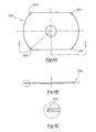
- FIG. 6A is a top view of a CD according to a second embodiment of the present invention, and engageable with the CD holder shown in FIG. 4;
- FIG. 6B is a sectional view taken along the line G-G in FIG. 6A;
- FIG. 6C is an enlarged view of the part encircled in FIG. 6B;
- FIG. 6D is a bottom view of the CD shown in FIG. 6A;
- FIG. 7 is a top perspective view of a third example of a holder for an optically readable information disc according to the present invention.
- FIG. 8A is a top view of the CD holder shown in FIG. 7;
- FIG. 8B is a sectional view taken along the line H-H in FIG. 8A;
- FIG. 8C is a sectional view taken along the line J-J in FIG. 8A;
- FIG. 9A is a top view of a CD according to a third embodiment of the present invention, and engageable with the CD holder shown in FIG. 7;
- FIG. 9B is a sectional view taken along the line K-K in FIG. 9A;
- FIG. 9C is a bottom view of the CD shown in FIG. 9A;
- FIG. 9D is a right side view of the CD shown in FIG. 9A;
- FIG. 10 is a top perspective view of a fourth example of a holder for an optically readable information disc according to the present invention.
- FIG. 11A is a top view of the CD holder shown in FIG. 10;
- FIG. 11B is a sectional view taken along the line M-M in FIG. 11A;
- FIG. 11C is a sectional view taken along the line N-N in FIG. 11A;
- FIG. 12A is a top view of a CD according to a fourth embodiment of the present invention, and engageable with the CD holder shown in FIG. 10;
- FIG. 12B is a sectional view taken along the line P-P in FIG. 12A;
- FIG. 12C is a bottom view of the CD shown in FIG. 12A;
- FIG. 12D is a right side view of the CD shown in FIG. 12A;
- FIG. 13 is a top perspective view of a fifth example of a holder for an optically readable information disc according to the present invention.
- FIG. 14A is a top view of the CD holder shown in FIG. 13;
- FIG. 14B is a sectional view taken along the line Q-Q in FIG. 14A;
- FIG. 15A is a top view of a CD according to a fifth embodiment of the present invention, and engageable with the CD holder shown in FIG. 13;
- FIG. 15B is a side view of the CD shown in FIG. 15A.
- FIG. 16 is a bottom perspective view of a CD according to a sixth embodiment of the present invention.
- FIGS. 1 to 2 D such show a first example of a holder for an optically readable information disc, and generally designated as 100 .
- the holder for an optically readable information disc according to the present invention will henceforth be discussed in the context of a CD holder, it should be understood that the holder can be used for holding other optically readable information discs, e.g. DVDs.
- the optically readable information disc is here described by reference to a CD, it should be understood that such may be other forms of optically readable information discs, e.g. DVDs.
- the disc is not limited to circular in shape only, but may be of other suitable shapes, as discussed below and illustrated in the accompanying drawings.
- the CD holder 100 is generally rectangular in shape, and has a generally planar base surface 102 . At the centre portion of the base surface 102 is a rigid peg 104 . It can be seen that the peg 104 is in the shape of a very short cylinder. The peg 104 is sized to be slightly smaller than the central hole of a CD with which it is to be engaged (to be discussed below), so that the peg 104 may be received within the central hole of the CD. However, the peg 104 does not have any positive engagement with the central hole of the CD, and thus the CD.
- a circular gutter 106 Surrounding the peg 104 is a circular gutter 106 .
- Two upwardly protruding nipples 108 are provided on the gutter 106 and diametrically opposed to each other. Both these nipples 108 are raised above the planar base surface 102 of the holder 100 . The function of the gutter 106 and the nipples 108 will be discussed below.
- a raised platform 110 At each longitudinal end of the holder 100 is a raised platform 110 .
- a CD suitable for being held by the holder 100 is shown in FIGS. 3A to 3 E, and generally designated as 150 .
- the CD 150 is in the general form of a card.
- On an upper side 152 of the CD 150 may be provided with graphics and/or text material.
- a hole 154 is provided at the centre region of the CD 150 .
- the peg 104 of the holder 100 is sized for the hole 154 .
- An underside 156 of the CD 150 are provided with a series of data tracks which may be illuminated and read by a source of coherent light, e.g. a laser.
- a stacking ring 158 On the underside 156 of the CD 150 is also provided with a stacking ring 158 which, when the CD 150 is engaged with the holder 100 , is received within the gutter 106 .
- Two small recesses 160 are provided on the stacking ring 158 and positioned diametrically opposite to each other.
- each curved longitudinal end 162 of the CD 150 is a continuous strip of stepped, chamfered or cut-off portion 164 , which allows the CD 150 to be retained by the holder 100 .
- the CD 150 may be rotated relative to the holder 100 in the direction indicated by the arrows in FIG. 3G, so that a lower stepped portion 166 enters into and is received within the recessed portion 112 of the holder 100 .
- the major axis X-X of the CD 150 will then be parallel to the major axis Y-Y of the holder 100 , and the nipples 108 of the gutter 106 of the holder 100 will be engaged with the recesses 160 on the stacking ring 158 of the CD 150 .
- Both the engagement between the lower stepped portion 166 and the recessed portion 112 , and the engagement between the nipples 108 and the recesses 160 will assist in holding and retaining the CD 150 to the holder 100 .
- the nipples 108 need not be diametrically opposed to each other, provided that they are appropriately positioned to engage with two recesses of the CD 150 .
- the CD 150 is to be released from the holder 100 , the CD 150 is to be rotated relative to the holder 100 until the lower stepped portions 166 are clear of the recessed portions 112 . In this position, the major axis X-X of the CD 150 will be generally parallel to the minor axis Z-Z of the holder 100 . The CD 150 and the holder 100 may then be disengaged from each other.
- the CD 150 is of a thickness such that, when the CD 150 and the holder 100 are engaged with each other, the upper surface 152 of the CD 150 is flush with the platforms 110 , so that a continuous planar upper surface is formed. It is thus possible to have graphics and/or text provided, e.g. printed, on the continuous planar upper surface so formed. Such a feature cannot be provided by existing CD holder, since the central peg arrangements so far provided have to be movable, thus there must be a space on the upper end of the peg arrangements. However, in the present invention, the peg 104 has a planar upper surface, which allows a continuous upper surface of the combined CD holder 100 and CD 150 to be formed.
- FIGS. 4 to 5 D A second example of a holder is shown in FIGS. 4 to 5 D, and generally designated as 200 .
- the general construction and shape of the holder 200 is similar to that of the holder 100 , except that, instead of having two continuous curved under-cut recessed portions 112 in the holder 100 , the holder 200 has two pairs of chamfered under-cut recessed portions 202 .
- Each of the two pairs of recessed portions 202 is provided at two ends of a curved inner edge 204 of a respective raised platform 206 .
- each of the recessed portions 202 has a surface which is inwardly inclined relative to a planar surface 208
- the rest of the inner edge 204 of the raised platform 206 has a surface which is perpendicular relative to the planar surface 208 .
- FIGS. 6A to 6 D A CD suitable for engagement with the holder 200 is shown in FIGS. 6A to 6 D, and generally designated as 250 . It can be seen that this CD 250 is similar to the CD 150 shown in FIGS. 3A to 3 E. However, instead of having two stripes of curved continuous stepped portions, as in the case of the CD 150 , the CD 250 has four chamfered portions 252 , each provided at a comer of the CD 250 . These chamfered portions 252 may be received within the under-cut recessed portions 202 of the holder 200 .
- the chamfered portions 252 of the CD 250 may be slid into or out of the recessed portions 202 in order to engage the CD 250 with, or disengage the CD 250 from, the holder 200 .
- FIGS. 7 to 8 D A third example of a holder is shown in FIGS. 7 to 8 D, and generally designated as 300 .
- the holder 300 is generally rectangular in shape, with a wider raised platform 302 at one longitudinal end, and a narrower raised platform 304 at another longitudinal end.
- the inner side 306 of the platform 302 has a straight edge 308 with a surface which is perpendicular to a planar surface 310 of the holder 300 .
- At each end of the straight edge 308 is an under-cut recessed portion 312 .
- Each of the recessed portions has a surface which is inwardly inclined relative to the planar surface 310 .
- the inner side of the platform 304 also has a straight edge 314 with a planar surface which is perpendicular to the planar surface 310 .
- a straight edge 314 with a planar surface which is perpendicular to the planar surface 310 .
- an under-cut recessed portion 316 is at each end of the straight edge 314 , each with a surface which is inwardly inclined relative to the planar surface 310 .
- the size and shape of the recessed portions 312 and 316 are the same.
- FIGS. 9A to 9 D A CD suitable for engagement with the holder 300 is shown in FIGS. 9A to 9 D, and generally designated as 350 .
- the CD 350 is generally rectangular in shape, and with a central hole, as in conventional arrangement.
- a chamfered portion 352 At each corner of the CD 350 is a chamfered portion 352 which is sized and shaped to be fitted within an under-cut recessed portion 312 or 316 of the holder 300 .
- FIGS. 10 to 11 C show a fourth example of a holder and generally designated as 400 .
- This holder 400 is similar in shape and structure to the holder 300 discussed above.
- the holder 400 also has a wider raised platform 402 with an inner side 404 .
- the main difference between the holder 300 and the holder 400 is that while the inner side 306 of the holder 300 has a planar surface which is perpendicular to a planar surface 310 of the holder 300 , the inner side 404 of the holder 400 is provided with a straight continuous under-cut portion 406 , which may be seen more clearly in FIG. 11B.
- Two inwardly-inclined under-cut portions 408 are provided at the ends of an inner side 410 of a narrower raised platform 412 .
- FIGS. 12A to 12 D show a CD, generally designated as 450 , suitable for engagement with the holder 400 discussed above.
- a CD generally designated as 450
- a straight stepped portion 452 with a lower stepped portion 454 which may be received within the under-cut portion 406 of the holder 400 .
- a chamfered portion 456 is provided at each of the ends of the edge opposite to the stepped portion 452 , which may be received within the under-cut portions 408 of the holder 400 .
- the lower stepped portion 454 is first inserted into the straight continuous under-cut portion 406 .
- the chamfered portions 456 are then snap-fitted into the under-cut portions 408 of the holder 400 .
- the chamfered portions 456 are snapped out of engagement with the under-cut portions 408 .
- the lower stepped portion 454 may then be removed from the under-cut portion 406 to disengage the CD 450 from the holder 400 .
- FIGS. 13 to 14 B A fifth example of a holder is shown in FIGS. 13 to 14 B, and generally designated as 500 .
- the holder 500 is generally square in shape, with a central generally circular lowered portion 502 for receiving a CD, to be discussed below.
- the lower portion 502 has a continuous circular side wall 504 which is perpendicular to a base surface 506 of the holder 500 , except two lock portions 508 which are arranged along the circular side wall 504 and diametrically opposite each other.
- each of the lock portions 508 has a surface which is inwardly inclined relative to the base surface 506 of the holder 500 .
- a CD suitable for engagement with the holder 500 is shown in FIGS. 15A and 15B, and generally designated as 550 .
- the CD 550 is circular in shape, and has a chamfered peripheral edge 552 .
- the CD 550 is placed above the holder 500 , with a central rigid circular peg 510 of the holder 500 received partly within a central hole 553 of the CD 550 , and with an under surface 554 facing the base surface 506 of the holder 500 .
- the chamfered edge 552 of the CD 550 is then snap-fitted with the lock portions 508 , to secure the CD 550 with the holder 500 .
- the chamfered edge 552 of the CD 550 is snapped out of engagement with the lock portions 508 of the holder 500 .
- FIG. 16 shows a CD 850 according to a sixth embodiment of the present invention.
- the CD 850 is in the general form of a card.
- a hole 852 is provided at the centre region of the CD 850 for engagement with a correspondingly sized and configured peg of an appropriate holder.
- An underside 854 of the CD 850 is provided with a series of data tracks which may be illuminated and read by laser.
- On the underside 854 of the CD 850 is also provided with a stacking ring 856 which protrudes away from the underside 854 of the CD 850 .
- Two small recesses 858 are provided on the stacking ring 856 and positioned diametrically opposite to each other, to serve the same function as the recesses 160 of the CD 150 discussed above.
- two ridges 860 which protrude away from the underside 854 are positioned beyond the data tracks.
- the ridges 860 are each in the shape of an arc of a circle whose diameter is larger than the width w of the CD 850 .
- a total of four recesses 862 a , 862 b , 862 c , 862 d are arranged along the ridges 860 .
- the recesses 862 a and 862 d are diametrically opposite to each other, and the recesses 862 b and 862 c diametrically opposite to each other.
- the data tracks are bounded in its inner side by the stacking ring 856 and in their outer side by the ridges 860 , so that the data tracks will not be damaged during relative movement between the CD 850 and the appropriate holder.
- the recesses 862 a , 862 b , 862 c , 862 d may receive engagement nipples on the appropriate holder for better engagement between the CD 850 and the holder.
Abstract
An optically readable information disc (150, 250, 350, 450, 550, 850) is disclosed as having an upper major surface (152), a lower major surface (156, 554, 854) and at least a peripheral edge (162) joining the major surfaces, further including engagement mechanism (164, 252, 352, 452, 456, 552) along at least part of the peripheral edge for engagement with a holder (100, 200, 300, 400, 500).
Description
- This invention relates to an optically readable information disc, e.g. compact disc (CD) and, in particular, such a disc adapted to be releasably engageable with a holder.
- Since the invention of optically readable information discs in around 1980, see e.g. U.S. Pat. No. 4,410,978 issued to U.S. Philips Corporation, various designs for containers or holders for such discs have been proposed. U.S. Pat. No. 4,874,085 and the equivalent European Patent No. 0 086 484 issued to Polygram GmbH relate to a storage container for disc-shaped information carriers, e.g. CD. The contents of these patent documents are incorporated herein for reference purposes.
- The storage container covered by the above patents issued to Polygram GmbH is generally called the “Original Jewel Box” (OJB). The OJB includes a bottom with a central peg arrangement for engaging the inner surface of the central hole of the CD. The central peg arrangement includes a number of resilient members whose exterior sides are adapted to engage the central hole of the CD. A main feature of the OJB is that the central peg arrangement and an elevated rest form a sole means for retaining the CD. In particular, the peripheral edge and the record information area of the CD are free of contact with the container.
- Since the OJB, a number of improvements and new designs relating to the central peg arrangement have been made, see, for example, DE 34 25 579 issued to Polygram GmbH, and WO 99/60563. All such new designs seek to enhance the retaining function of the central peg arrangement.
- It is an object of the present invention to provide an optically readable information disc which at least does not solely rely on the engagement between its central hole and a central peg arrangement of the holder. It is also an object of the present invention to provide a useful alternative to the public.
- It is a further object of the present invention to provide an optically readable information disc which, when engaged with a holder, provides a flush planar upper surface on which graphics and/or text may be provided.
- According to the present invention, there is provided an optically readable information disc having an upper major surface, a lower major surface and at least a peripheral edge joining said major surfaces, characterized in that means is provided along at least part of said peripheral edge for engagement with a holder.
- Embodiments of the present invention will now be described, by way of examples only, and with reference to the accompanying drawings, in which:-
- FIG. 1 is a top perspective view of a first example of a holder for an optically readable information disc according to the present invention;
- FIG. 2A is a top view of the holder shown in FIG. 1;
- FIG. 2B is a sectional view taken along the line A-A in FIG. 2A;
- FIG. 2C is a sectional view taken along the line B-B in FIG. 2A;
- FIG. 2D is a side view of the holder shown in FIG. 2A;
- FIG. 3A is a top view of a CD according to a first embodiment of the present invention, engageable with the holder shown in FIG. 1;
- FIG. 3B is a bottom view of the CD shown in FIG. 3A;
- FIG. 3C is a side view of the CD shown in FIG. 3A;
- FIG. 3D is a sectional view taken along the line C-C in FIG. 3A;
- FIG. 3E is a sectional view taken along the line D-D in FIG. 3A;
- FIG. 3F is a view showing the way in which the holder shown in FIG. 1 and the CD shown in FIG. 3A are engaged with each other;
- FIG. 3G shows the way of engagement and disengagement between the holder shown in FIG. 1 and the CD shown in FIG. 3A;
- FIG. 4 is a top perspective view of a second example of a holder for an optically readable information disc according to the present invention;
- FIG. 5A is a top view of the CD holder shown in FIG. 4;
- FIG. 5B is a sectional view taken along the line E-E in FIG. 5A;
- FIG. 5C is a sectional view taken along the line F-F of FIG. 5A;
- FIG. 5D is a side view of the CD holder shown in FIG. 5A;
- FIG. 6A is a top view of a CD according to a second embodiment of the present invention, and engageable with the CD holder shown in FIG. 4;
- FIG. 6B is a sectional view taken along the line G-G in FIG. 6A;
- FIG. 6C is an enlarged view of the part encircled in FIG. 6B;
- FIG. 6D is a bottom view of the CD shown in FIG. 6A;
- FIG. 7 is a top perspective view of a third example of a holder for an optically readable information disc according to the present invention;
- FIG. 8A is a top view of the CD holder shown in FIG. 7;
- FIG. 8B is a sectional view taken along the line H-H in FIG. 8A;
- FIG. 8C is a sectional view taken along the line J-J in FIG. 8A;
- FIG. 9A is a top view of a CD according to a third embodiment of the present invention, and engageable with the CD holder shown in FIG. 7;
- FIG. 9B is a sectional view taken along the line K-K in FIG. 9A;
- FIG. 9C is a bottom view of the CD shown in FIG. 9A;
- FIG. 9D is a right side view of the CD shown in FIG. 9A;
- FIG. 10 is a top perspective view of a fourth example of a holder for an optically readable information disc according to the present invention;
- FIG. 11A is a top view of the CD holder shown in FIG. 10;
- FIG. 11B is a sectional view taken along the line M-M in FIG. 11A;
- FIG. 11C is a sectional view taken along the line N-N in FIG. 11A;
- FIG. 12A is a top view of a CD according to a fourth embodiment of the present invention, and engageable with the CD holder shown in FIG. 10;
- FIG. 12B is a sectional view taken along the line P-P in FIG. 12A;
- FIG. 12C is a bottom view of the CD shown in FIG. 12A;
- FIG. 12D is a right side view of the CD shown in FIG. 12A;
- FIG. 13 is a top perspective view of a fifth example of a holder for an optically readable information disc according to the present invention;
- FIG. 14A is a top view of the CD holder shown in FIG. 13;
- FIG. 14B is a sectional view taken along the line Q-Q in FIG. 14A;
- FIG. 15A is a top view of a CD according to a fifth embodiment of the present invention, and engageable with the CD holder shown in FIG. 13;
- FIG. 15B is a side view of the CD shown in FIG. 15A; and
- FIG. 16 is a bottom perspective view of a CD according to a sixth embodiment of the present invention.
- Referring firstly to FIGS. 1 to 2D, such show a first example of a holder for an optically readable information disc, and generally designated as 100. While the holder for an optically readable information disc according to the present invention will henceforth be discussed in the context of a CD holder, it should be understood that the holder can be used for holding other optically readable information discs, e.g. DVDs. Similarly, while the optically readable information disc is here described by reference to a CD, it should be understood that such may be other forms of optically readable information discs, e.g. DVDs. It should also be understood that, in the context of the present invention, the disc is not limited to circular in shape only, but may be of other suitable shapes, as discussed below and illustrated in the accompanying drawings.
- The
CD holder 100 is generally rectangular in shape, and has a generallyplanar base surface 102. At the centre portion of thebase surface 102 is arigid peg 104. It can be seen that thepeg 104 is in the shape of a very short cylinder. Thepeg 104 is sized to be slightly smaller than the central hole of a CD with which it is to be engaged (to be discussed below), so that thepeg 104 may be received within the central hole of the CD. However, thepeg 104 does not have any positive engagement with the central hole of the CD, and thus the CD. - Surrounding the
peg 104 is acircular gutter 106. Two upwardly protrudingnipples 108 are provided on thegutter 106 and diametrically opposed to each other. Both thesenipples 108 are raised above theplanar base surface 102 of theholder 100. The function of thegutter 106 and thenipples 108 will be discussed below. - At each longitudinal end of the
holder 100 is a raisedplatform 110. Formed between each of theplatforms 110 and theplanar surface 102 is an under-cut recessedportion 112. These recessedportions 112 follow the generally curvedinner side 114 of each of the raisedplatform 110. - A CD suitable for being held by the
holder 100 is shown in FIGS. 3A to 3E, and generally designated as 150. TheCD 150 is in the general form of a card. On anupper side 152 of theCD 150 may be provided with graphics and/or text material. Ahole 154 is provided at the centre region of theCD 150. As discussed above, thepeg 104 of theholder 100 is sized for thehole 154. Anunderside 156 of theCD 150 are provided with a series of data tracks which may be illuminated and read by a source of coherent light, e.g. a laser. On theunderside 156 of theCD 150 is also provided with a stackingring 158 which, when theCD 150 is engaged with theholder 100, is received within thegutter 106. Twosmall recesses 160 are provided on the stackingring 158 and positioned diametrically opposite to each other. - Along each curved
longitudinal end 162 of theCD 150 is a continuous strip of stepped, chamfered or cut-offportion 164, which allows theCD 150 to be retained by theholder 100. In particular, in order to engage theCD 150 with theholder 100, and as shown in FIGS. 3F and 3G, it is first necessary to have thepeg 104 of theholder 100 received within thehole 154 of the CD, with theunderside 156 of theCD 150 facing theplanar surface 102, and with the major axis X-X of the CD 150 (see FIG. 3B) positioned generally parallel to the minor axis Z-Z of theholder 100. In this position, theCD 150 may be rotated relative to theholder 100 in the direction indicated by the arrows in FIG. 3G, so that a lower steppedportion 166 enters into and is received within the recessedportion 112 of theholder 100. - When the lower stepped
portion 166 is fully received within the recessedportion 112 of theholder 100, the major axis X-X of theCD 150 will then be parallel to the major axis Y-Y of theholder 100, and thenipples 108 of thegutter 106 of theholder 100 will be engaged with therecesses 160 on the stackingring 158 of theCD 150. Both the engagement between the lower steppedportion 166 and the recessedportion 112, and the engagement between thenipples 108 and therecesses 160 will assist in holding and retaining theCD 150 to theholder 100. In this connection, it should be understood that thenipples 108 need not be diametrically opposed to each other, provided that they are appropriately positioned to engage with two recesses of theCD 150. - If the
CD 150 is to be released from theholder 100, theCD 150 is to be rotated relative to theholder 100 until the lower steppedportions 166 are clear of the recessedportions 112. In this position, the major axis X-X of theCD 150 will be generally parallel to the minor axis Z-Z of theholder 100. TheCD 150 and theholder 100 may then be disengaged from each other. - It should be noted that, the
CD 150 is of a thickness such that, when theCD 150 and theholder 100 are engaged with each other, theupper surface 152 of theCD 150 is flush with theplatforms 110, so that a continuous planar upper surface is formed. It is thus possible to have graphics and/or text provided, e.g. printed, on the continuous planar upper surface so formed. Such a feature cannot be provided by existing CD holder, since the central peg arrangements so far provided have to be movable, thus there must be a space on the upper end of the peg arrangements. However, in the present invention, thepeg 104 has a planar upper surface, which allows a continuous upper surface of the combinedCD holder 100 andCD 150 to be formed. - A second example of a holder is shown in FIGS. 4 to 5D, and generally designated as 200. The general construction and shape of the
holder 200 is similar to that of theholder 100, except that, instead of having two continuous curved under-cut recessedportions 112 in theholder 100, theholder 200 has two pairs of chamfered under-cut recessedportions 202. Each of the two pairs of recessedportions 202 is provided at two ends of a curvedinner edge 204 of a respective raisedplatform 206. While each of the recessedportions 202 has a surface which is inwardly inclined relative to aplanar surface 208, the rest of theinner edge 204 of the raisedplatform 206 has a surface which is perpendicular relative to theplanar surface 208. - A CD suitable for engagement with the
holder 200 is shown in FIGS. 6A to 6D, and generally designated as 250. It can be seen that thisCD 250 is similar to theCD 150 shown in FIGS. 3A to 3E. However, instead of having two stripes of curved continuous stepped portions, as in the case of theCD 150, theCD 250 has four chamferedportions 252, each provided at a comer of theCD 250. These chamferedportions 252 may be received within the under-cut recessedportions 202 of theholder 200. - As in the engagement between the
holder 100 and theCD 150, the chamferedportions 252 of theCD 250 may be slid into or out of the recessedportions 202 in order to engage theCD 250 with, or disengage theCD 250 from, theholder 200. In addition, because of the inherent resilience of theCD 250, it is also possible to engage theCD 250 with, or disengage theCD 250 from, theholder 200 by snapping each of the chamferedportions 252 into or out of a respective recessedportion 202 of the holder. - A third example of a holder is shown in FIGS. 7 to 8D, and generally designated as 300. The
holder 300 is generally rectangular in shape, with a wider raisedplatform 302 at one longitudinal end, and a narrower raisedplatform 304 at another longitudinal end. The inner side 306 of theplatform 302 has astraight edge 308 with a surface which is perpendicular to aplanar surface 310 of theholder 300. At each end of thestraight edge 308 is an under-cut recessedportion 312. Each of the recessed portions has a surface which is inwardly inclined relative to theplanar surface 310. The inner side of theplatform 304 also has astraight edge 314 with a planar surface which is perpendicular to theplanar surface 310. At each end of thestraight edge 314 is an under-cut recessedportion 316, each with a surface which is inwardly inclined relative to theplanar surface 310. In this arrangement, the size and shape of the recessedportions - A CD suitable for engagement with the
holder 300 is shown in FIGS. 9A to 9D, and generally designated as 350. TheCD 350 is generally rectangular in shape, and with a central hole, as in conventional arrangement. At each corner of theCD 350 is a chamferedportion 352 which is sized and shaped to be fitted within an under-cut recessedportion holder 300. - To engage the
CD 350 with theholder 300, two adjoining chamferedportions 352 are inserted within the recessedportions 312. The remainingchamfered portions 352 are then snap-fitted into the recessedportions 316. In order to disengage theCD 350 from theholder 300, the two chamferedportions 352 received within the recessedportions 316 are snapped out engagement with the recessedportions 316. TheCD 350 may then be removed from theholder 300. - FIGS. 10 to 11C show a fourth example of a holder and generally designated as 400. This
holder 400 is similar in shape and structure to theholder 300 discussed above. Theholder 400 also has a wider raisedplatform 402 with aninner side 404. The main difference between theholder 300 and theholder 400 is that while the inner side 306 of theholder 300 has a planar surface which is perpendicular to aplanar surface 310 of theholder 300, theinner side 404 of theholder 400 is provided with a straight continuous under-cutportion 406, which may be seen more clearly in FIG. 11B. Two inwardly-inclined under-cutportions 408 are provided at the ends of aninner side 410 of a narrower raisedplatform 412. - FIGS. 12A to 12D show a CD, generally designated as 450, suitable for engagement with the
holder 400 discussed above. Along one edge of theCD 450 is provided a straight steppedportion 452 with a lower steppedportion 454 which may be received within the under-cutportion 406 of theholder 400. At each of the ends of the edge opposite to the steppedportion 452 is provided a chamferedportion 456, which may be received within the under-cutportions 408 of theholder 400. - To engage the
CD 450 with theholder 400, the lower steppedportion 454 is first inserted into the straight continuous under-cutportion 406. Thechamfered portions 456 are then snap-fitted into the under-cutportions 408 of theholder 400. To disengage theCD 450 from theholder 400, the chamferedportions 456 are snapped out of engagement with the under-cutportions 408. The lower steppedportion 454 may then be removed from the under-cutportion 406 to disengage theCD 450 from theholder 400. - A fifth example of a holder is shown in FIGS. 13 to 14B, and generally designated as 500. The
holder 500 is generally square in shape, with a central generally circular loweredportion 502 for receiving a CD, to be discussed below. Thelower portion 502 has a continuouscircular side wall 504 which is perpendicular to abase surface 506 of theholder 500, except twolock portions 508 which are arranged along thecircular side wall 504 and diametrically opposite each other. As can be seen more clearly in FIG. 14B, each of thelock portions 508 has a surface which is inwardly inclined relative to thebase surface 506 of theholder 500. - A CD suitable for engagement with the
holder 500 is shown in FIGS. 15A and 15B, and generally designated as 550. TheCD 550 is circular in shape, and has a chamferedperipheral edge 552. To engage theCD 550 with theholder 500, theCD 550 is placed above theholder 500, with a central rigidcircular peg 510 of theholder 500 received partly within acentral hole 553 of theCD 550, and with an undersurface 554 facing thebase surface 506 of theholder 500. Thechamfered edge 552 of theCD 550 is then snap-fitted with thelock portions 508, to secure theCD 550 with theholder 500. To disengage theCD 550 from theholder 500, the chamferededge 552 of theCD 550 is snapped out of engagement with thelock portions 508 of theholder 500. - FIG. 16 shows a
CD 850 according to a sixth embodiment of the present invention. As in the case of theCD 150 shown in FIGS. 3A and 3B, as discussed above, theCD 850 is in the general form of a card. Ahole 852 is provided at the centre region of theCD 850 for engagement with a correspondingly sized and configured peg of an appropriate holder. Anunderside 854 of theCD 850 is provided with a series of data tracks which may be illuminated and read by laser. On theunderside 854 of theCD 850 is also provided with a stackingring 856 which protrudes away from theunderside 854 of theCD 850. Twosmall recesses 858 are provided on the stackingring 856 and positioned diametrically opposite to each other, to serve the same function as therecesses 160 of theCD 150 discussed above. - To further ensure that the data tracks outside of the stacking
ring 856 of theCD 850 will not be scratched when theCD 850 is rotated relative to an appropriate holder, tworidges 860 which protrude away from theunderside 854 are positioned beyond the data tracks. Theridges 860 are each in the shape of an arc of a circle whose diameter is larger than the width w of theCD 850. A total of fourrecesses ridges 860. Therecesses recesses ring 856 and in their outer side by theridges 860, so that the data tracks will not be damaged during relative movement between theCD 850 and the appropriate holder. Therecesses CD 850 and the holder. - It should be understood that the above only illustrates examples whereby the present invention may be carried out, and that various modifications and/or alterations may be made thereto without departing from the spirit of the invention.
- It should also be understood that certain features of the invention, which are, for clarity, described in the context of separate embodiments, may be provided in combination in a single embodiment. Conversely, various features of the invention which are, for brevity, described in the context of a single embodiment, may also be provided separately or in any appropriate sub-combinations.
Claims (16)
1. An optically readable information disc having an upper major surface, a lower-major surface and at least a peripheral edge joining said major surfaces, characterized in that means is provided along at least part of said peripheral edge for engagement with a holder.
2. A disc according to claim 1 further characterized in that said upper major surface is smaller than said lower major surface.
3. A disc according to claim 1 further characterized in that said peripheral edge includes at least one stepped/chamfered portion.
4. A disc according to claim 3 characterized in that said stepped/chamfered portion is substantially straight.
5. A disc according to claim 3 characterized in that said stepped/chamfered portion is curved.
6. A disc according to claim 3 further characterized in that said peripheral edge includes a plurality of stepped/chamfered portions.
7. A disc according to claim 6 further characterized in that said peripheral edge includes two opposite stepped/chamfered portions, each at a longitudinal end of said disc.
8. A disc according to claim 6 further characterized in that said plurality of stepped/chamfered portions are provided at comers of said disc.
9. A disc according to claim 1 further including at least a recess on a stacking ring on said lower major surface.
10. A disc according to claim 9 further including a plurality of recesses on said stacking ring.
11. A disc according to claim 10 further characterized in that at least two diametrically opposite recesses are positioned on said stacking ring.
12. A disc according to claim 1 further including a pair of curved ridges on said lower major surface.
13. A disc according to claim 12 further characterized in that each of said ridges is of the shape of an arc of a circle of a diameter larger than the width of said disc.
14. A disc according to claim 12 further characterized in that at least a recess is provided along each of said curved ridges.
15. A disc according to claim 14 further characterized in that said recesses are diametrically opposite to each other.
16. A disc according to claim 14 further characterized in that a plurality of said recesses are provided along each of said curved ridges.
Applications Claiming Priority (3)
| Application Number | Priority Date | Filing Date | Title |
|---|---|---|---|
| CN01102921.9 | 2001-04-24 | ||
| HK01102921A HK1041776A2 (en) | 2001-04-24 | 2001-04-24 | A holder for an optically readable information disc |
| PCT/CN2002/000269 WO2002086877A1 (en) | 2001-04-24 | 2002-04-19 | An optically readable information disc |
Publications (1)
| Publication Number | Publication Date |
|---|---|
| US20040172645A1 true US20040172645A1 (en) | 2004-09-02 |
Family
ID=10945300
Family Applications (2)
| Application Number | Title | Priority Date | Filing Date |
|---|---|---|---|
| US10/475,813 Abandoned US20040172645A1 (en) | 2001-04-24 | 2002-04-19 | Optically readable information disc |
| US10/128,426 Expired - Fee Related US6874158B2 (en) | 2001-04-24 | 2002-04-24 | Holder for an optically readable information disc |
Family Applications After (1)
| Application Number | Title | Priority Date | Filing Date |
|---|---|---|---|
| US10/128,426 Expired - Fee Related US6874158B2 (en) | 2001-04-24 | 2002-04-24 | Holder for an optically readable information disc |
Country Status (9)
| Country | Link |
|---|---|
| US (2) | US20040172645A1 (en) |
| EP (2) | EP1395989A4 (en) |
| JP (2) | JP3081988U (en) |
| CN (3) | CN2485756Y (en) |
| CA (1) | CA2445142A1 (en) |
| GB (1) | GB2374860B (en) |
| HK (2) | HK1041776A2 (en) |
| TW (1) | TW556936U (en) |
| WO (2) | WO2002086899A1 (en) |
Families Citing this family (10)
| Publication number | Priority date | Publication date | Assignee | Title |
|---|---|---|---|---|
| HK1041776A2 (en) * | 2001-04-24 | 2002-07-12 | Chak Sang Simon Chan | A holder for an optically readable information disc |
| JP2002326695A (en) * | 2001-04-27 | 2002-11-12 | Willone Corp | Jacket for optical disk |
| GB0218858D0 (en) * | 2002-08-14 | 2002-09-25 | Koninkl Philips Electronics Nv | Holder for a storage medium |
| US20040056102A1 (en) * | 2002-09-20 | 2004-03-25 | Yau Sheung Cheung | Multi-Purpose disc |
| US7185814B2 (en) * | 2002-10-16 | 2007-03-06 | Dcard, Inc. | Layer structure and method of manufacture for optical memory strip (OMS) |
| FR2846775B1 (en) * | 2002-11-05 | 2006-11-24 | Francis Laroche | PACKAGING FOR DIGITAL RECORDING RECORDING MEDIUM |
| US7213749B2 (en) * | 2004-02-17 | 2007-05-08 | R&R Card Systems, Inc. | Interactive multimedia smart affinity card |
| US8177129B2 (en) | 2004-02-17 | 2012-05-15 | Timothy D. Larin | Interactive multimedia smart affinity card with flash memory |
| US20070115778A1 (en) * | 2005-11-21 | 2007-05-24 | International Business Machines Corporation | Physical identification of an optical disc |
| US20080232230A1 (en) * | 2007-03-23 | 2008-09-25 | Power Media Cd Tech International Co., Ltd. | Joining structure of a disc medium and a multifunctional card |
Citations (29)
| Publication number | Priority date | Publication date | Assignee | Title |
|---|---|---|---|---|
| US3951264A (en) * | 1974-10-29 | 1976-04-20 | Dynastor, Inc. | Flexible disc cartridge |
| US4410978A (en) * | 1980-10-15 | 1983-10-18 | U.S. Philips Corporation | Optically readable information disk |
| US4433410A (en) * | 1982-06-30 | 1984-02-21 | Rca Corporation | Protective cartridge for optical discs |
| US4463850A (en) * | 1983-05-10 | 1984-08-07 | Rca Corporation | Video disc caddy |
| US4536867A (en) * | 1984-04-16 | 1985-08-20 | Qume Corporation | Self-centering disc |
| US4837784A (en) * | 1987-03-14 | 1989-06-06 | Sony Corporation | Apparatus for adapting the diameter of a disk-like recording medium |
| US4874085A (en) * | 1982-02-16 | 1989-10-17 | Polygram Gmbh | Storage cassette for high storage density, disc-shaped information carriers |
| US5059774A (en) * | 1987-10-15 | 1991-10-22 | Ricoh Company, Ltd. | Seek and track control for a rectangular optical card handling apparatus |
| US5121278A (en) * | 1985-12-18 | 1992-06-09 | Tdk Corporation | Disc cartridge having disc supporting arrangement |
| US5128922A (en) * | 1987-09-29 | 1992-07-07 | Sharp Kabushiki Kaisha | Optical disk with glass substrate and method of producing same |
| US5537389A (en) * | 1992-11-30 | 1996-07-16 | Hitachi Maxwell, Ltd. | Disk cartridge having a single closing energizer for closing two independently opened shutters |
| US5787069A (en) * | 1996-09-13 | 1998-07-28 | Digital Armor Inc. | Protective cover for an optical disc |
| US5867477A (en) * | 1992-04-28 | 1999-02-02 | Sony Corporation | Optical disk with snap-fit magnetized hub |
| US5912875A (en) * | 1996-09-13 | 1999-06-15 | Digital Armor Inc. | Applicator for protective cover for an optical disc |
| US5938902A (en) * | 1995-01-17 | 1999-08-17 | Hmt Technology Corporation | Disc-handling apparatus |
| US6078557A (en) * | 1997-05-15 | 2000-06-20 | Pierson; Gerald A. | Method of using optical compact disc |
| US6214430B1 (en) * | 1998-04-10 | 2001-04-10 | Lg Electronics Inc. | Disc recording medium and method of fabricating the same |
| US6400675B1 (en) * | 1997-05-15 | 2002-06-04 | Benjamin James Everidge | Compact disc with a disc tray alignment means |
| US20020136155A1 (en) * | 2001-03-06 | 2002-09-26 | Chieh-Ho Chen | CD safe to hold |
| US6484940B1 (en) * | 1999-05-11 | 2002-11-26 | Digital Castles | Data storage card having both linear and annular data regions |
| US6510124B1 (en) * | 1997-10-14 | 2003-01-21 | David B. Wood | CD card |
| US6612762B1 (en) * | 1999-05-31 | 2003-09-02 | Seiko Precision Inc. | Printer |
| US6754165B2 (en) * | 2002-01-25 | 2004-06-22 | Robert C. Burnett | Diameter reducible, multiple part optical disk |
| US6760280B1 (en) * | 1999-07-10 | 2004-07-06 | Karl-Heinz Schoppe | Optical memory card in the form of a disk |
| US6814286B2 (en) * | 2001-12-17 | 2004-11-09 | Medea International (Taiwan) Corporation | Card for multi-purpose using |
| US6857575B2 (en) * | 2000-03-17 | 2005-02-22 | Fuji Magnetics Gmbh | Optical business card |
| US6874158B2 (en) * | 2001-04-24 | 2005-03-29 | Chak Sang Simon Chan | Holder for an optically readable information disc |
| US6948182B2 (en) * | 2000-03-24 | 2005-09-20 | Tomoaki Ito | Optical disc |
| US7213749B2 (en) * | 2004-02-17 | 2007-05-08 | R&R Card Systems, Inc. | Interactive multimedia smart affinity card |
Family Cites Families (31)
| Publication number | Priority date | Publication date | Assignee | Title |
|---|---|---|---|---|
| US2285139A (en) * | 1940-11-18 | 1942-06-02 | Lloyd J Andres | Record holder |
| US4148491A (en) * | 1978-01-06 | 1979-04-10 | Stark Martin F | Phonograph record adapter |
| US4771890A (en) * | 1986-05-09 | 1988-09-20 | International Business Machines Corporation | Disk retainer and packaging system for optical disks |
| DE3725616A1 (en) * | 1987-08-03 | 1989-02-16 | Philips & Du Pont Optical | STORAGE CASSETTE FOR A DISK-SHAPED INFORMATION CARRIER |
| JPH06501667A (en) * | 1990-10-22 | 1994-02-24 | ハンセン、ダレル エル | optical storage disc protector |
| CA2066936A1 (en) * | 1991-05-16 | 1992-11-17 | Donald Spector | Compact disc package |
| JP3116559B2 (en) * | 1991-10-23 | 2000-12-11 | ソニー株式会社 | Device for mounting disc cartridge in recording and / or playback device |
| WO1994014161A1 (en) | 1992-12-08 | 1994-06-23 | Doukas Robert Fonias | Protective covers for optical discs |
| KR0165269B1 (en) * | 1993-06-01 | 1999-03-20 | 김광호 | Cartridge molder locking device of disc player |
| US5690218A (en) | 1994-12-30 | 1997-11-25 | William Gary McCamy | Compact disc storage case |
| US5579296A (en) * | 1995-01-18 | 1996-11-26 | Cyberwerks Interactive, L.L.C. | Optically readable thin film digital data storage medium |
| JP3145631B2 (en) * | 1995-05-25 | 2001-03-12 | インターナショナル・ビジネス・マシーンズ・コーポレ−ション | Cartridge, disk drive and disk media library for disk without hub |
| AU6600996A (en) * | 1995-07-27 | 1997-02-26 | Paul J. Neuner | Optical disc protector and method for applying same |
| US5769216A (en) * | 1996-02-27 | 1998-06-23 | Collins; William | Holder for compact disc and the like |
| DE19611082A1 (en) * | 1996-03-21 | 1996-08-22 | Peter Rapp | Compact disc packaging |
| DE19626925A1 (en) * | 1996-07-04 | 1998-01-08 | Polygram Manufacturing & Distr | Housing with a holding arrangement arranged on a base plate |
| US5823334A (en) * | 1996-08-16 | 1998-10-20 | Giovanni; Chandra D. | Compact disc high friction bottom coaster |
| WO1998011542A1 (en) | 1996-09-13 | 1998-03-19 | Digital Armor Inc. | Protective cover for an optical disc |
| JPH10208359A (en) * | 1997-01-24 | 1998-08-07 | Sony Corp | Electronic apparatus |
| GB2325215A (en) * | 1997-05-15 | 1998-11-18 | Zenith Print & Packaging Limit | Holder, especially for a disc |
| GB9712536D0 (en) * | 1997-06-17 | 1997-08-20 | Alpha Tech Moulding Limited | Disc-retainer |
| US6016298A (en) * | 1997-06-25 | 2000-01-18 | Adivan High Tech Ag | Calling card |
| US5813525A (en) * | 1997-07-08 | 1998-09-29 | R.R. Donnelley & Sons Company | Compact disc holder |
| US5984093A (en) * | 1997-11-07 | 1999-11-16 | Frick Management Group Limited | Automatic storage media release mechanism for storage media package |
| US6276524B1 (en) * | 1998-01-19 | 2001-08-21 | Magnetic Imatge, S.A. | Case for disc-shaped optical recording medium such as CD, DVD or the like |
| US6077583A (en) * | 1998-03-03 | 2000-06-20 | Park; Arnold | Digital information guard |
| US5988375A (en) | 1999-03-26 | 1999-11-23 | Snyr Yih Metallic Co., Ltd. | Disc box structure |
| DE19918275A1 (en) | 1999-04-22 | 2000-11-02 | Ursula Luckow | Device for receiving disc-shaped information carriers |
| JP2003104479A (en) * | 1999-05-07 | 2003-04-09 | Teikoku Denso:Kk | Protective cover for recording medium |
| AU4839799A (en) | 1999-06-29 | 2001-01-31 | Carl Vance Hedberg | Structural integrity recovery system |
| GB9916996D0 (en) * | 1999-07-20 | 1999-09-22 | Price Robin J | Improvements in and relating to portable |
-
2001
- 2001-04-24 HK HK01102921A patent/HK1041776A2/en not_active IP Right Cessation
- 2001-05-03 TW TW090207178U patent/TW556936U/en unknown
- 2001-05-08 GB GB0111210A patent/GB2374860B/en not_active Expired - Fee Related
- 2001-05-22 JP JP2001003195U patent/JP3081988U/en not_active Expired - Lifetime
- 2001-05-24 CN CN01224627U patent/CN2485756Y/en not_active Expired - Fee Related
-
2002
- 2002-04-16 CN CN02105540A patent/CN1383151A/en active Pending
- 2002-04-19 EP EP02764034A patent/EP1395989A4/en not_active Withdrawn
- 2002-04-19 EP EP02764035A patent/EP1407452A4/en not_active Withdrawn
- 2002-04-19 WO PCT/CN2002/000268 patent/WO2002086899A1/en not_active Application Discontinuation
- 2002-04-19 CN CNB028088255A patent/CN1234118C/en not_active Expired - Fee Related
- 2002-04-19 US US10/475,813 patent/US20040172645A1/en not_active Abandoned
- 2002-04-19 WO PCT/CN2002/000269 patent/WO2002086877A1/en active Application Filing
- 2002-04-19 CA CA002445142A patent/CA2445142A1/en not_active Abandoned
- 2002-04-23 JP JP2002120086A patent/JP4116319B2/en not_active Expired - Fee Related
- 2002-04-24 US US10/128,426 patent/US6874158B2/en not_active Expired - Fee Related
-
2003
- 2003-03-12 HK HK03101799.8A patent/HK1051084B/en not_active IP Right Cessation
Patent Citations (29)
| Publication number | Priority date | Publication date | Assignee | Title |
|---|---|---|---|---|
| US3951264A (en) * | 1974-10-29 | 1976-04-20 | Dynastor, Inc. | Flexible disc cartridge |
| US4410978A (en) * | 1980-10-15 | 1983-10-18 | U.S. Philips Corporation | Optically readable information disk |
| US4874085A (en) * | 1982-02-16 | 1989-10-17 | Polygram Gmbh | Storage cassette for high storage density, disc-shaped information carriers |
| US4433410A (en) * | 1982-06-30 | 1984-02-21 | Rca Corporation | Protective cartridge for optical discs |
| US4463850A (en) * | 1983-05-10 | 1984-08-07 | Rca Corporation | Video disc caddy |
| US4536867A (en) * | 1984-04-16 | 1985-08-20 | Qume Corporation | Self-centering disc |
| US5121278A (en) * | 1985-12-18 | 1992-06-09 | Tdk Corporation | Disc cartridge having disc supporting arrangement |
| US4837784A (en) * | 1987-03-14 | 1989-06-06 | Sony Corporation | Apparatus for adapting the diameter of a disk-like recording medium |
| US5128922A (en) * | 1987-09-29 | 1992-07-07 | Sharp Kabushiki Kaisha | Optical disk with glass substrate and method of producing same |
| US5059774A (en) * | 1987-10-15 | 1991-10-22 | Ricoh Company, Ltd. | Seek and track control for a rectangular optical card handling apparatus |
| US5867477A (en) * | 1992-04-28 | 1999-02-02 | Sony Corporation | Optical disk with snap-fit magnetized hub |
| US5537389A (en) * | 1992-11-30 | 1996-07-16 | Hitachi Maxwell, Ltd. | Disk cartridge having a single closing energizer for closing two independently opened shutters |
| US5938902A (en) * | 1995-01-17 | 1999-08-17 | Hmt Technology Corporation | Disc-handling apparatus |
| US5787069A (en) * | 1996-09-13 | 1998-07-28 | Digital Armor Inc. | Protective cover for an optical disc |
| US5912875A (en) * | 1996-09-13 | 1999-06-15 | Digital Armor Inc. | Applicator for protective cover for an optical disc |
| US6078557A (en) * | 1997-05-15 | 2000-06-20 | Pierson; Gerald A. | Method of using optical compact disc |
| US6400675B1 (en) * | 1997-05-15 | 2002-06-04 | Benjamin James Everidge | Compact disc with a disc tray alignment means |
| US6510124B1 (en) * | 1997-10-14 | 2003-01-21 | David B. Wood | CD card |
| US6214430B1 (en) * | 1998-04-10 | 2001-04-10 | Lg Electronics Inc. | Disc recording medium and method of fabricating the same |
| US6484940B1 (en) * | 1999-05-11 | 2002-11-26 | Digital Castles | Data storage card having both linear and annular data regions |
| US6612762B1 (en) * | 1999-05-31 | 2003-09-02 | Seiko Precision Inc. | Printer |
| US6760280B1 (en) * | 1999-07-10 | 2004-07-06 | Karl-Heinz Schoppe | Optical memory card in the form of a disk |
| US6857575B2 (en) * | 2000-03-17 | 2005-02-22 | Fuji Magnetics Gmbh | Optical business card |
| US6948182B2 (en) * | 2000-03-24 | 2005-09-20 | Tomoaki Ito | Optical disc |
| US20020136155A1 (en) * | 2001-03-06 | 2002-09-26 | Chieh-Ho Chen | CD safe to hold |
| US6874158B2 (en) * | 2001-04-24 | 2005-03-29 | Chak Sang Simon Chan | Holder for an optically readable information disc |
| US6814286B2 (en) * | 2001-12-17 | 2004-11-09 | Medea International (Taiwan) Corporation | Card for multi-purpose using |
| US6754165B2 (en) * | 2002-01-25 | 2004-06-22 | Robert C. Burnett | Diameter reducible, multiple part optical disk |
| US7213749B2 (en) * | 2004-02-17 | 2007-05-08 | R&R Card Systems, Inc. | Interactive multimedia smart affinity card |
Also Published As
| Publication number | Publication date |
|---|---|
| JP3081988U (en) | 2001-11-22 |
| US6874158B2 (en) | 2005-03-29 |
| CN2485756Y (en) | 2002-04-10 |
| JP4116319B2 (en) | 2008-07-09 |
| CN1234118C (en) | 2005-12-28 |
| CN1505816A (en) | 2004-06-16 |
| EP1407452A4 (en) | 2008-02-27 |
| GB2374860B (en) | 2004-06-02 |
| EP1395989A1 (en) | 2004-03-10 |
| CN1383151A (en) | 2002-12-04 |
| JP3851873B2 (en) | 2006-11-29 |
| JP2004522246A (en) | 2004-07-22 |
| HK1041776A2 (en) | 2002-07-12 |
| TW556936U (en) | 2003-10-01 |
| WO2002086877A1 (en) | 2002-10-31 |
| GB0111210D0 (en) | 2001-06-27 |
| CA2445142A1 (en) | 2002-10-31 |
| WO2002086899A1 (en) | 2002-10-31 |
| GB2374860A (en) | 2002-10-30 |
| HK1051084B (en) | 2005-04-15 |
| EP1395989A4 (en) | 2007-07-04 |
| JP2003026273A (en) | 2003-01-29 |
| HK1051084A1 (en) | 2003-07-18 |
| US20020154597A1 (en) | 2002-10-24 |
| EP1407452A1 (en) | 2004-04-14 |
Similar Documents
| Publication | Publication Date | Title |
|---|---|---|
| ES2125054T5 (en) | DEVICE FOR RETAINING A COMPACT DISC. | |
| US7431154B2 (en) | Security storage container | |
| US20040172645A1 (en) | Optically readable information disc | |
| EP0775361B1 (en) | Disc case | |
| CA2174248C (en) | Clear molded thermoplastic compact disc supporting tray | |
| CA2350042C (en) | Disc rosette with release tab | |
| WO1991004926A2 (en) | Disk shipper | |
| EP0941536B1 (en) | Housing for a disc-shaped information carrier | |
| US5593032A (en) | Disc retainer device | |
| US20030019771A1 (en) | Apparatus for holding a media storage disk | |
| JP3851873B6 (en) | Optically readable information disc | |
| KR20040028764A (en) | Thin compact disk holder | |
| US6557710B1 (en) | Media disc holder | |
| US7708139B2 (en) | Recording medium storage package having improved rosette | |
| EP1085514B1 (en) | Data storage unit | |
| JP3138994U (en) | Multi-layer disc case with index spacer | |
| GB2418199A (en) | Media holding apparatus | |
| US6860572B1 (en) | Storage and retrieval device for compact discs | |
| US20050279656A1 (en) | Optical disc storing case | |
| JPH05201482A (en) | Case for at least one sheet of high density data disk | |
| JPH11189286A (en) | Optical disk sheet and optical disk | |
| ZA200201000B (en) | Optical data carrier in the form of a disk. | |
| US20060041901A1 (en) | Disk cartridge and storage assembly | |
| JP2005178874A (en) | Disc holding and storing case | |
| JP2000043969A (en) | Disk holder and disk case |
Legal Events
| Date | Code | Title | Description |
|---|---|---|---|
| STCB | Information on status: application discontinuation |
Free format text: ABANDONED -- FAILURE TO RESPOND TO AN OFFICE ACTION |