US20050017841A1 - Data transmission system using a human body as a signal transmission path - Google Patents
Data transmission system using a human body as a signal transmission path Download PDFInfo
- Publication number
- US20050017841A1 US20050017841A1 US10/921,269 US92126904A US2005017841A1 US 20050017841 A1 US20050017841 A1 US 20050017841A1 US 92126904 A US92126904 A US 92126904A US 2005017841 A1 US2005017841 A1 US 2005017841A1
- Authority
- US
- United States
- Prior art keywords
- signal
- transmitter
- ground
- electrode
- data
- Prior art date
- Legal status (The legal status is an assumption and is not a legal conclusion. Google has not performed a legal analysis and makes no representation as to the accuracy of the status listed.)
- Abandoned
Links
Images


Classifications
-
- A—HUMAN NECESSITIES
- A61—MEDICAL OR VETERINARY SCIENCE; HYGIENE
- A61B—DIAGNOSIS; SURGERY; IDENTIFICATION
- A61B5/00—Measuring for diagnostic purposes; Identification of persons
- A61B5/0002—Remote monitoring of patients using telemetry, e.g. transmission of vital signals via a communication network
- A61B5/0026—Remote monitoring of patients using telemetry, e.g. transmission of vital signals via a communication network characterised by the transmission medium
- A61B5/0028—Body tissue as transmission medium, i.e. transmission systems where the medium is the human body
-
- G—PHYSICS
- G07—CHECKING-DEVICES
- G07C—TIME OR ATTENDANCE REGISTERS; REGISTERING OR INDICATING THE WORKING OF MACHINES; GENERATING RANDOM NUMBERS; VOTING OR LOTTERY APPARATUS; ARRANGEMENTS, SYSTEMS OR APPARATUS FOR CHECKING NOT PROVIDED FOR ELSEWHERE
- G07C9/00—Individual registration on entry or exit
- G07C9/20—Individual registration on entry or exit involving the use of a pass
- G07C9/28—Individual registration on entry or exit involving the use of a pass the pass enabling tracking or indicating presence
-
- H—ELECTRICITY
- H04—ELECTRIC COMMUNICATION TECHNIQUE
- H04B—TRANSMISSION
- H04B13/00—Transmission systems characterised by the medium used for transmission, not provided for in groups H04B3/00 - H04B11/00
- H04B13/005—Transmission systems in which the medium consists of the human body
Definitions
- the present invention relates to a data transmission system using a human body as a signal path, and more particularly to a system composed of a wearable transmitter, a receiver adapted to be connected to an associated equipment which utilize data transmitted from the transmitter, and a garment integrally holding two electrodes for passing the data through the human body.
- U.S. patent application Ser. No. 09/605,357 discloses a data transmission system using the human body as a signal path.
- the system includes a portable transmitter in the form of a wrist watch to be worn on a user, and a signal receiver.
- the transmitter has a pair of electrodes on the back of the wrist watch for direct contact with the skin of the user.
- One electrode acts as a signal electrode which is connected through a portion of the user's body to a touch electrode of the signal receiver, while the other electrode acts as a ground electrode which is coupled through the other portion of the user's body to a circuit ground of the signal receiver to complete a signal path through the user's body for data transmission from the wrist watch to the signal receiver.
- the present invention has been achieved to provide a data transmission system which is capable of assuring successful data transmission without requiring a special attention to the user.
- the system in accordance with the present invention comprises a transmitter adapted to be carried by the user and a receiver adapted to be connected to an associated equipment which utilizes data transmitted from the transmitter.
- the transmitter has a ground electrode to be placed in close proximity to the human body, a signal electrode to be placed also in close proximity to the human body in a spatially spaced relation from the ground electrode, a data memory storing first data, a first modulator for converting the first data into a first modulated voltage signal, and a first signal transmitter which applies the first modulated voltage signal across the signal electrode and the ground electrode.
- the receiver includes a circuit ground adapted to be connected to the ground, a touch electrode adapted for direct contact with a portion of the human body carrying the transmitter, a signal detector connected across the signal electrode and the circuit ground to detect the first modulated voltage signal, and a demodulator which converts the first modulated voltage signal back into the first data.
- the characterizing feature of the present invention resides in that the system includes a garment which is adapted to be worn by a user and integrates the ground and signal electrodes in such a manner that at least one of the electrodes is kept in a closely facing relation to the skin of the user, thereby establishing an electrical path extending through a portion of the human body for signal transmission from the transmitter to the receiver. With the integration of the two electrodes into the garment, the user wearing the garment as an everyday clothes or uniform such as a white gown can be easy and convenient to carry the transmitter for successful transmission of the data to the receiver.
- each of the ground and signal electrodes is formed by a plurality of electrically conductive threads and is sewed to be integrated into the garment.
- the electrodes can be easily integrated into the garment and cannot sacrifice comfortableness of the garment.
- Each electrode made of the electrically conductive threads can be woven into a fabric so as to be lined on the garment.
- the electrode of the conductive threads can be woven into an indispensable part of the garment. With the use of the electrical conductive threads, the garment provided with the resulting electrodes can be washed like ordinary clothes, which enhances availability of the system.
- the ground electrode is preferred to be located on the garment closer to the foot of the user than the signal electrode for establishing a consistent electrical path through the human body. That is, the electrical path is composed of a first fraction path extending from the ground electrode down to the foot of the user and through the ground to the circuit ground of the receiver, and a second fraction path extending from the signal electrode towards and through a finger of the user to the touch electrode of the receiver without interfering the first fraction path, thereby assuring efficient and reliable data transmission.
- the transmitter has a case which accommodates an electrical circuitry realizing the first modulator and the first signal transmitter, and which is formed as a separate article from the electrodes.
- the case is provided with terminals for electrically connecting the circuitry with the ground and signal electrodes.
- the garment is additionally provided with a ground lead and a signal lead which extend respectively from the ground and signal electrodes for connection with the terminals of the case.
- Both of the ground and signal leads are formed by a strand of the electrically conductive threads and are sewed on the garment.
- the leads can be also easily and consistently integrated into the garment to retain comfortableness of the garment.
- a coupling member is included in the system to make the case detachable from the garment and at the same time make the electrical circuitry detachable from the electrodes, i.e., the corresponding leads.
- the coupling member may be realized by a spring-loaded clip which is pivotally supported to the case so as to be movable between a pinching position and a release position.
- the clip is formed with the terminals which are electrically isolated from each other for connection respectively with the ground and signal leads at the pinching position.
- the coupling member may comprise a pair of first fasteners each composed of one of a socket and a ball forming a snap button for mounting the case to the garment, and a pair of second fasteners each composed of the other of the socket and the ball.
- the first fasteners are fixed on the case and connected across the first signal transmitter of the circuitry, while the second fasteners are fixed on the garment and are permanently connected to respectively to the ground and signal electrodes.
- the second fasteners are preferably held in direct contact with the ground and signal electrodes, respectively formed of the electrically conductive threads, thereby substantially eliminating the leads from the garment.
- the ground and signal electrodes may be in the form of annular bands provided inside of a sleeve of the garment in a spaced relation from each other along the length of the sleeve.
- the case is made water-tight for sealing the electric circuitry so that the garment can be washed like ordinal clothes even with the case.
- the case may be in the form of a plate which encapsulate the circuitry and a battery energizing the circuitry.
- the plate can be utilized also as a nameplate as is usual with the white gown worn by a physician, nurse, and a laboratory worker.
- FIG. 1 is a schematic view illustrating a basic concept of a data transmission system in accordance with the present invention
- FIG. 2 is a block diagram of a wearable transmitter utilized in the above system
- FIG. 3 is a block diagram of an associated receiver utilized in the above system
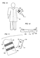
- FIGS. 4 and 5 are front and rear views of a garment utilized in the above system to integrate a ground electrode and a signal electrode;
- FIG. 6 is a perspective view showing one typical application of the above system
- FIG. 7 is a rear perspective view of a case in the form of a nameplate accommodating an electric circuitry of the transmitter and detachable to the garment;
- FIG. 8 is a perspective view of the case and a portion of the garment to which the case is attached;
- FIG. 9 is a view showing the nameplate as attached to the garment.
- FIG. 10 is schematic view illustrating another embodiment of the system.
- FIG. 11 is an exploded perspective view showing ground and signal electrodes integrated into a sleeve of the garment and a transmitter case detachable thereto;
- FIG. 12 is a side view of the transmitter case.
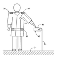
- FIG. 1 there is shown a principle of a data transmission system using a human body as a signal transmission path.
- the system includes a wearable transmitter 10 adapted to be worn on the human body, and a receiver 40 adapted to be connected to an equipment such as a personal computer 60 which utilizes data transmitted from the transmitter for controlled operation of the computer 60 , for example, a verified log-in of the user.
- the transmitter 10 is connected to a ground electrode 31 and a signal electrode 32 which are integrated into a garment 30 worn by a user in close proximity to the skin of the user.
- a signal path is established which extends from the signal electrode 32 through a portion of the user's body, the touch electrode 41 , an internal circuit of the receiver 40 , a circuit ground 49 of the receiver 40 , the ground G, the other portion of the user's body, the ground electrode 31 and an internal circuit of the transmitter 10 .
- the signal path extending through the human body is indicated by dotted lines.
- a voltage signal applied across the electrodes 31 and 32 is transmitted to the receiver 40 when the user touches the touch electrode 41 .
- the circuit ground of the receiver 40 is connected to the ground G through a ground line 64 common to the computer 60 for the sake of simplicity.
- the circuit ground may be capacitively connected to the ground G or even capacitively connected directly to the major portion of the user's body for establishing the signal path.
- the transmitter 10 includes an electric circuitry and a battery 12 which are accommodated within a case 11 .
- the circuitry includes a data memory 13 storing data to be transmitted, a controller 14 , a modulator 15 modulating the data into a modulated voltage signal, a signal transmitter 16 applying the modulated voltage signal across the signal electrode 32 and the ground electrode 31 on the garment 30 .
- a signal detector 20 which is connected to detect a start signal transmitted from the receiver 40 through the signal electrode 32 . The start signal is received across the signal electrode 32 and a circuit ground 19 .
- the circuit ground 19 may be connected to the ground electrode 31 .
- the controller 14 and the signal detector 20 are constantly energized by the battery 12 to be ready for detecting the start signal from the receiver 40 .
- the controller 14 In the non-operative condition where the transmitter 10 is not transmitting the data, the controller 14 is kept in a sleep mode of consuming less electric current from the battery 12 .
- the signal detector 20 wakes up the controller 14 which in turn energizes the data memory 13 , the modulator 15 , and the signal transmitter 16 to apply the modulated voltage signal across the signal electrode 32 and the ground electrode 31 for initiating the data transmission.
- the controller 14 incorporates a timer which starts upon detection of the start signal to provide a predetermined time during which the data is transmitted.
- the controller 14 After the elapse of the predetermined time, the controller 14 responds to deenergize the modulator 15 , the signal transmitter 16 and the data memory 13 .
- the controller 14 includes power switches 21 and 22 which are actuated by the signal detector 20 and the timer to selectively energize and deenergize the modulator 15 , the signal transmitter 16 and the data memory 13 . Dotted lines in FIG. 2 show power supply lines from the battery 12 . Thus, after transmitting the data, the controller 14 goes back into the sleep mode of consuming less current or energy but being kept ready to detect of the start signal for another data transmission.
- the transmitter 10 optionally includes a display 24 for visual indication of the data stored in the data memory 15 .
- the receiver 40 includes various circuits connected to the touch electrode 41 on the exterior of a housing of the receiver.
- the circuits are energized by a power source 61 provided in the computer 60 to which the receiver 40 is attached.
- the circuits are commonly connected to a circuit ground 49 which is in turn connected to a ground terminal 69 of the computer for connection with the ground.
- the circuits include a touch sensor 42 which is connected to the touch electrode 41 to give a touch signal when the touch electrode 41 is touched by the user's body.
- Also included in the circuits are a start signal generator 43 , a signal detector 44 , a demodulator 45 , and a controller 46 which controls the operations of the circuits.
- the signal transmitter 43 applies the start signal to the touch electrode 41 in response to the touch signal.
- the signal detector 44 detects the modulated voltage signal which is transmitted from the transmitter 10 and received across the touch electrode 41 and the circuit ground 49 .
- the modulated voltage signal thus detected is demodulated at the demodulator 45 to derive the first data which is then fed to the computer 60 to be processed thereat.
- the first data includes a user's identification code which is verified at a processor 62 of the computer with reference to various codes assigned to different users and stored in a data memory 63 . When the user's ID is verified as a correct one, the computer completes the log-in sequence to permit the access by the user.
- the controller 46 and the touch sensor 42 are energized to be ready for detection of the touching.
- the touch sensor 42 gives the touch signal to the controller 46 which responds to close switches 51 and 52 to energize the signal transmitter 43 , the signal detector 44 , and the demodulator 45 , thereby generating the start signal and making the circuits ready for receiving the data from the transmitter 10 .
- the controller 46 also includes a timer which starts, upon receiving the touch signal, to provide a predetermined time interval during which the data transmission from the first transceiver 10 is expected to complete.
- the controller 46 responds to open the switches 51 and 52 , deenergizing the signal transmitter 43 , the signal detector 44 , and the demodulator 45 .
- the receiver 40 is kept in a sleep mode of consuming less electricity until the touch electrode 41 is touched.
- Dotted lines in FIG. 3 show power supply lines.
- the receiver 40 further includes an interface 54 in the form of the USB for transferring the data to the computer 60 as well as for receiving the power from a power supply 61 .
- the transmitter 10 and the receiver 40 are designed to effect a bilateral data transmission therebetween.
- the transmitter 10 additionally includes a demodulator 25 for demodulating data transmitted from the receiver 40 and that the receiver 40 additionally includes a modulator 47 for modulating the data to be transmitted from the receiver 40 .
- the modulator 47 of gives a modulated voltage signal indicative of the data to be transmitted to the transmitter 10 .
- the signal transmitter 43 of the receiver 40 is responsible for applying the modulated voltage signal to the touch electrode 41 for data transmission back to the transmitter 10 .
- the touch sensor 42 provides a touch signal in response to which the controller 46 energizes the modulator 47 , the signal transmitter 43 , the demodulator 45 , and the signal detector 44 .
- the controller 46 retrieves the data from the data memory 63 of the computer 60 and instructs to give and apply the modulated voltage signal indicative of the data.
- the controller 14 of the transmitter 10 activates the data memory 13 and performs a suitable processing of the data from the data memory 13 in consideration of the data received from the receiver 40 .
- the controller 14 updates the data of the data memory 13 depending upon the result of the processing.
- the controller 14 activates the modulator 15 and the signal transmitter 16 so as to transmit the modulated voltage signal indicative of the updated data to the receiver 40 through the electrodes 31 and 32 .
- the modulated voltage signal received at the receiver 40 is converted into the data which is utilized by the controller 46 for a controlled operation of the computer or passed to another equipment to be processed thereat for a specific operation of the equipment.
- the two-way data transmission is made between the transmitter and the receiver in a half-duplex manner.
- the system may be designed to have more than one data transmission cycles in which the one-way data transmission from either of the transmitter and the receiver repeats twice or more. In such case, the data in the data memory 13 of the transmitter 10 is modified or updated by the data transmitted from the receiver 40 .
- the transmitter 10 is kept in the sleep mode until the modulated voltage signal is received from the receiver 40 , and comes back again in the sleep mode after the data transmission between the transmitter and the receiver is completed.
- the data memory 13 , the modulator 15 , the signal transmitter 16 , and the demodulator 21 are energized by closure of the switches 21 and 22 only for a predetermined time period starting from receiving the modulated voltage signal from the receiver. It is within the predetermined time period that the data transmission between the transmitter and the receiver is completed.
- the receiver is kept in the sleep mode until the touch electrode 41 is touched by the human body, and come back to the sleep mode after the data transmission between the first and second transceivers are completed.
- the signal transmitter 43 , the modulator 47 , the signal detector 44 , and the demodulator 45 are energized by closure of switches 51 and 52 only for a predetermined time period starting from the touch electrode being touched.
- the garment 30 to which the electrodes 31 and 32 are attached is selected, for example, as a white gown that is always worn by a particular user like a physician, nurse, and laboratory worker while engaging a job requiring a verification of the user.
- the garment 30 is not limited to the white gown and may take various types of the clothes such as a uniform for an office, factory, school, and the like organization or group.
- Each of the ground electrode 31 and the signal electrode 32 is in the form of a fabric made by electrically conductive threads and is sewed on the inner surface of the garment 30 with the signal electrode 32 disposed at the shoulders of the garment 30 and with the ground electrode 31 disposed around the lower part of the garment corresponding to a hip and buttocks of the user, as shown in FIGS. 4 and 5 .
- the electrodes may be woven into the garment as indispensable parts thereof. The above selected location of the electrodes 31 and 32 is particularly effective when the user access the computer 60 while sitting on a chair as shown in FIG. 6 .
- the ground electrode 31 receives a counter force from the seat of the chair to be pressed against the buttocks of the user, while the signal electrode 32 is pressed against the shoulders of the user with the help of weight of the garment for reliable electrical connection of the electrodes to the human body. It is noted in this connection that the ground electrode 31 is located closer to the foot of the user than the signal electrode 32 along the signal path extending through the human body so that the path extending from the signal electrode 32 toward the finger of the user can be substantially free from, i.e., cannot be substantially interfered with the path extending from the ground electrode 31 to the foot of the user for reliable signal transmission between the transmitter 10 and the receiver 40 .
- the case 11 of the transmitter 10 is formed into a nameplate which is made water-tight and accommodates therein the electric circuitry 28 forming the various functional circuits and elements as shown in FIG. 2 , and the battery 12 energizing the circuits.
- the case 11 is provided with a spring-loaded clip 70 so as to be detachable to the garment, for example, at a breast pocket.
- the clip 70 is pivotally supported at its one end to the case so as to be movable between a pinching position and a release position.
- the clip 70 includes a pair of conductive terminals 71 and 72 which are connected to the electric circuitry, i.e., across the signal transmitter 16 and which are isolated by a dielectric strip 73 . As shown in FIGS.
- the terminals 71 and 72 come into engagement respectively with pads 35 and 36 provided at one ends of respective leads 33 and 34 extending from the individual electrodes 31 and 32 .
- the electric circuitry of the transmitter is connected to electrodes.
- the leads 33 and 34 are also made of electrically conductive threads, more particularly, strands of the conductive threads sewed on or into the garment 30 .
- FIG. 10 to 12 show another preferred embodiment of the present invention in which a case 11 A of the transmitter 10 A is detachable to a sleeve of the garment 30 by means of snap buttons which are normally utilized in association with clothing. That is, the snap button is made of conductive material and composed of a socket 81 and a ball 82 .
- a ground electrode 31 A and a signal electrode 32 A are provided at the sleeve of the garment 30 for direct coupling with the electric circuitry of the transmitter 10 A.
- the case 11 A is in the form of a water-tight thin plate accommodating the electric circuitry 28 A of the transmitter 10 A and the battery 12 A.
- the case 11 A is provided with a pair of the sockets 81 which are internally connected to the electrical circuitry of the transmitter 10 A, while the electrodes 31 A and 32 A are provided respectively with the balls 82 .
- each electrode is made of conductive threads woven and sewed on or into the sleeve to form an annular band surrounding the sleeve in close proximity to the skin of the user wearing the garment for establishing a reliable electrical connection to the human body.
- the balls 82 are sewed directly on the electrodes by use of the conductive threads or press-fitted into the electrode, thereby eliminating the leads extending otherwise by a certain distance along the garment from the electrodes.
- the balls may be provided on the case, or a mixed pair of the ball and socket is provide on the case.
- the ground and signal electrodes 31 and 32 are explained to be formed by the electrically conductive threads, however, the each electrode may be formed as a metal plating deposited on the surface of the garment or deposited on a fabric which is sewed on the garment.
- the garment into which the electrodes are integrated is not limited to the garment like the white gown and may be any other kinds of the clothing that is constantly worn by the user who is in access to the verified system. Therefore, the clothing may include an armband and wristband integrating the electrodes to which the case of the transmitter can be made electrically and physically detachable by-use of the above described snap buttons.
- the illustrated embodiments show only one application where both of the electrodes are kept in close facing relation with the skin of the user so that both of the electrodes are in direct electrical connection to the user's body, however, it is equally possible that one of the electrodes is in direct facing relation, i.e., electrical connection to the user's body, while the other of the electrodes is arranged to face away from the user's skin for capacitive connection to the receiver through the air.
- the illustrated embodiment is arranged to verify the data, i.e., the user's ID at the computer 60
- the receiver 40 may be arranged to equip the processor and the data memory so as to have a function of verifying the data from the transmitter, and providing a verified output to an associated device for permitting the access or a required control of the device, for example, permitting an entry of the user into a restricted area.
Abstract
A data transmission system using a human body as a signal transmission path includes a transmitter and a receiver. The transmitter uses a pair of electrodes which are held in close proximity to the skin of the human body. The transmitter transmits data to the receiver through the signal transmission path partly extending through the human body when a user carrying the transmitter touches a touch electrode of the receiver. The electrodes are integrated into a garment worn by the user in such a manner that the electrodes are kept in a closely facing relation to the skin of the user, thereby establishing the electrical path extending through the human body. With the integration of the two electrodes into the garment, the user wearing the garment as an everyday clothes or uniform can be easy and convenient to carry the transmitter for successful transmission of the data.
Description
- The present patent document is a continuation of U.S. application Ser. No. 09/948,638 filed on Sep. 10, 2001, and in turn claims priority to JP 2001-138479 filed on May 9, 2001, the entire contents of each of which are herein incorporated by reference.
- 1. Field of the Invention
- The present invention relates to a data transmission system using a human body as a signal path, and more particularly to a system composed of a wearable transmitter, a receiver adapted to be connected to an associated equipment which utilize data transmitted from the transmitter, and a garment integrally holding two electrodes for passing the data through the human body.
- 2. Description of the Prior Art
- U.S. patent application Ser. No. 09/605,357 discloses a data transmission system using the human body as a signal path. The system includes a portable transmitter in the form of a wrist watch to be worn on a user, and a signal receiver. The transmitter has a pair of electrodes on the back of the wrist watch for direct contact with the skin of the user. One electrode acts as a signal electrode which is connected through a portion of the user's body to a touch electrode of the signal receiver, while the other electrode acts as a ground electrode which is coupled through the other portion of the user's body to a circuit ground of the signal receiver to complete a signal path through the user's body for data transmission from the wrist watch to the signal receiver. When using this system used for a verified access to a place or database, however, the user is always required to keep in mind to carry the dedicated wrist watch having the electrodes. This may be sometimes inconvenient and even troublesome for the user who has his own wrist watch.
- In view of the above inconvenience, the present invention has been achieved to provide a data transmission system which is capable of assuring successful data transmission without requiring a special attention to the user. The system in accordance with the present invention comprises a transmitter adapted to be carried by the user and a receiver adapted to be connected to an associated equipment which utilizes data transmitted from the transmitter. The transmitter has a ground electrode to be placed in close proximity to the human body, a signal electrode to be placed also in close proximity to the human body in a spatially spaced relation from the ground electrode, a data memory storing first data, a first modulator for converting the first data into a first modulated voltage signal, and a first signal transmitter which applies the first modulated voltage signal across the signal electrode and the ground electrode. The receiver includes a circuit ground adapted to be connected to the ground, a touch electrode adapted for direct contact with a portion of the human body carrying the transmitter, a signal detector connected across the signal electrode and the circuit ground to detect the first modulated voltage signal, and a demodulator which converts the first modulated voltage signal back into the first data. The characterizing feature of the present invention resides in that the system includes a garment which is adapted to be worn by a user and integrates the ground and signal electrodes in such a manner that at least one of the electrodes is kept in a closely facing relation to the skin of the user, thereby establishing an electrical path extending through a portion of the human body for signal transmission from the transmitter to the receiver. With the integration of the two electrodes into the garment, the user wearing the garment as an everyday clothes or uniform such as a white gown can be easy and convenient to carry the transmitter for successful transmission of the data to the receiver.
- Preferably, each of the ground and signal electrodes is formed by a plurality of electrically conductive threads and is sewed to be integrated into the garment. Thus, the electrodes can be easily integrated into the garment and cannot sacrifice comfortableness of the garment. Each electrode made of the electrically conductive threads can be woven into a fabric so as to be lined on the garment. Alternatively, the electrode of the conductive threads can be woven into an indispensable part of the garment. With the use of the electrical conductive threads, the garment provided with the resulting electrodes can be washed like ordinary clothes, which enhances availability of the system.
- The ground electrode is preferred to be located on the garment closer to the foot of the user than the signal electrode for establishing a consistent electrical path through the human body. That is, the electrical path is composed of a first fraction path extending from the ground electrode down to the foot of the user and through the ground to the circuit ground of the receiver, and a second fraction path extending from the signal electrode towards and through a finger of the user to the touch electrode of the receiver without interfering the first fraction path, thereby assuring efficient and reliable data transmission.
- In a preferred embodiment where both of the ground and signal electrodes are held on the garment so as to come into a closely facing relation with the skin of the user, the transmitter has a case which accommodates an electrical circuitry realizing the first modulator and the first signal transmitter, and which is formed as a separate article from the electrodes. The case is provided with terminals for electrically connecting the circuitry with the ground and signal electrodes. In this connection, the garment is additionally provided with a ground lead and a signal lead which extend respectively from the ground and signal electrodes for connection with the terminals of the case. Both of the ground and signal leads are formed by a strand of the electrically conductive threads and are sewed on the garment. Thus, the leads can be also easily and consistently integrated into the garment to retain comfortableness of the garment.
- A coupling member is included in the system to make the case detachable from the garment and at the same time make the electrical circuitry detachable from the electrodes, i.e., the corresponding leads. The coupling member may be realized by a spring-loaded clip which is pivotally supported to the case so as to be movable between a pinching position and a release position. The clip is formed with the terminals which are electrically isolated from each other for connection respectively with the ground and signal leads at the pinching position.
- Instead of the clip, the coupling member may comprise a pair of first fasteners each composed of one of a socket and a ball forming a snap button for mounting the case to the garment, and a pair of second fasteners each composed of the other of the socket and the ball. The first fasteners are fixed on the case and connected across the first signal transmitter of the circuitry, while the second fasteners are fixed on the garment and are permanently connected to respectively to the ground and signal electrodes. When using the snap button to make the case detachable from the garment, the second fasteners are preferably held in direct contact with the ground and signal electrodes, respectively formed of the electrically conductive threads, thereby substantially eliminating the leads from the garment. In this connection, the ground and signal electrodes may be in the form of annular bands provided inside of a sleeve of the garment in a spaced relation from each other along the length of the sleeve.
- Preferably, the case is made water-tight for sealing the electric circuitry so that the garment can be washed like ordinal clothes even with the case. Further, the case may be in the form of a plate which encapsulate the circuitry and a battery energizing the circuitry. Thus, the plate can be utilized also as a nameplate as is usual with the white gown worn by a physician, nurse, and a laboratory worker.
- These and still other objects and advantageous features will become more apparent from the following description of the preferred embodiments when taken in conjunction with the attached drawings.
-
FIG. 1 is a schematic view illustrating a basic concept of a data transmission system in accordance with the present invention; -
FIG. 2 is a block diagram of a wearable transmitter utilized in the above system; -
FIG. 3 is a block diagram of an associated receiver utilized in the above system; -
FIGS. 4 and 5 are front and rear views of a garment utilized in the above system to integrate a ground electrode and a signal electrode; -
FIG. 6 is a perspective view showing one typical application of the above system; -
FIG. 7 is a rear perspective view of a case in the form of a nameplate accommodating an electric circuitry of the transmitter and detachable to the garment; -
FIG. 8 is a perspective view of the case and a portion of the garment to which the case is attached; -
FIG. 9 is a view showing the nameplate as attached to the garment; -
FIG. 10 is schematic view illustrating another embodiment of the system; -
FIG. 11 is an exploded perspective view showing ground and signal electrodes integrated into a sleeve of the garment and a transmitter case detachable thereto; and -
FIG. 12 is a side view of the transmitter case. - Referring first to
FIG. 1 , there is shown a principle of a data transmission system using a human body as a signal transmission path. The system includes awearable transmitter 10 adapted to be worn on the human body, and areceiver 40 adapted to be connected to an equipment such as apersonal computer 60 which utilizes data transmitted from the transmitter for controlled operation of thecomputer 60, for example, a verified log-in of the user. Thetransmitter 10 is connected to aground electrode 31 and asignal electrode 32 which are integrated into agarment 30 worn by a user in close proximity to the skin of the user. When the user carrying thetransmitter 10 touches atouch electrode 41 of thereceiver 40, a signal path is established which extends from thesignal electrode 32 through a portion of the user's body, thetouch electrode 41, an internal circuit of thereceiver 40, acircuit ground 49 of thereceiver 40, the ground G, the other portion of the user's body, theground electrode 31 and an internal circuit of thetransmitter 10. The signal path extending through the human body is indicated by dotted lines. Thus, a voltage signal applied across theelectrodes receiver 40 when the user touches thetouch electrode 41. InFIG. 1 , the circuit ground of thereceiver 40 is connected to the ground G through aground line 64 common to thecomputer 60 for the sake of simplicity. However, the circuit ground may be capacitively connected to the ground G or even capacitively connected directly to the major portion of the user's body for establishing the signal path. - As shown in
FIG. 2 , thetransmitter 10 includes an electric circuitry and abattery 12 which are accommodated within acase 11. The circuitry includes adata memory 13 storing data to be transmitted, acontroller 14, amodulator 15 modulating the data into a modulated voltage signal, asignal transmitter 16 applying the modulated voltage signal across thesignal electrode 32 and theground electrode 31 on thegarment 30. Also included in the circuitry is asignal detector 20 which is connected to detect a start signal transmitted from thereceiver 40 through thesignal electrode 32. The start signal is received across thesignal electrode 32 and acircuit ground 19. Thecircuit ground 19 may be connected to theground electrode 31. Only thecontroller 14 and thesignal detector 20 are constantly energized by thebattery 12 to be ready for detecting the start signal from thereceiver 40. In the non-operative condition where thetransmitter 10 is not transmitting the data, thecontroller 14 is kept in a sleep mode of consuming less electric current from thebattery 12. When the start signal is received as a consequence of the user touching thetouch electrode 41, thesignal detector 20 wakes up thecontroller 14 which in turn energizes thedata memory 13, themodulator 15, and thesignal transmitter 16 to apply the modulated voltage signal across thesignal electrode 32 and theground electrode 31 for initiating the data transmission. Thecontroller 14 incorporates a timer which starts upon detection of the start signal to provide a predetermined time during which the data is transmitted. After the elapse of the predetermined time, thecontroller 14 responds to deenergize themodulator 15, thesignal transmitter 16 and thedata memory 13. For this purpose, thecontroller 14 includes power switches 21 and 22 which are actuated by thesignal detector 20 and the timer to selectively energize and deenergize themodulator 15, thesignal transmitter 16 and thedata memory 13. Dotted lines inFIG. 2 show power supply lines from thebattery 12. Thus, after transmitting the data, thecontroller 14 goes back into the sleep mode of consuming less current or energy but being kept ready to detect of the start signal for another data transmission. Thetransmitter 10 optionally includes adisplay 24 for visual indication of the data stored in thedata memory 15. - As shown in
FIG. 3 , thereceiver 40 includes various circuits connected to thetouch electrode 41 on the exterior of a housing of the receiver. The circuits are energized by apower source 61 provided in thecomputer 60 to which thereceiver 40 is attached. The circuits are commonly connected to acircuit ground 49 which is in turn connected to aground terminal 69 of the computer for connection with the ground. The circuits include atouch sensor 42 which is connected to thetouch electrode 41 to give a touch signal when thetouch electrode 41 is touched by the user's body. Also included in the circuits are astart signal generator 43, asignal detector 44, ademodulator 45, and acontroller 46 which controls the operations of the circuits. Thesignal transmitter 43 applies the start signal to thetouch electrode 41 in response to the touch signal. Thesignal detector 44 detects the modulated voltage signal which is transmitted from thetransmitter 10 and received across thetouch electrode 41 and thecircuit ground 49. The modulated voltage signal thus detected is demodulated at thedemodulator 45 to derive the first data which is then fed to thecomputer 60 to be processed thereat. For example, the first data includes a user's identification code which is verified at aprocessor 62 of the computer with reference to various codes assigned to different users and stored in adata memory 63. When the user's ID is verified as a correct one, the computer completes the log-in sequence to permit the access by the user. - Under the non-operating condition where the
touch electrode 41 is not touched by the human body, only thecontroller 46 and thetouch sensor 42 are energized to be ready for detection of the touching. Upon thetouch electrode 41 being touched, thetouch sensor 42 gives the touch signal to thecontroller 46 which responds to closeswitches signal transmitter 43, thesignal detector 44, and thedemodulator 45, thereby generating the start signal and making the circuits ready for receiving the data from thetransmitter 10. Thecontroller 46 also includes a timer which starts, upon receiving the touch signal, to provide a predetermined time interval during which the data transmission from thefirst transceiver 10 is expected to complete. After the elapse of the predetermined time interval, thecontroller 46 responds to open theswitches signal transmitter 43, thesignal detector 44, and thedemodulator 45. Thus, thereceiver 40 is kept in a sleep mode of consuming less electricity until thetouch electrode 41 is touched. Dotted lines inFIG. 3 show power supply lines. Thereceiver 40 further includes aninterface 54 in the form of the USB for transferring the data to thecomputer 60 as well as for receiving the power from apower supply 61. - Further, the
transmitter 10 and thereceiver 40 are designed to effect a bilateral data transmission therebetween. For this purpose, thetransmitter 10 additionally includes ademodulator 25 for demodulating data transmitted from thereceiver 40 and that thereceiver 40 additionally includes amodulator 47 for modulating the data to be transmitted from thereceiver 40. Themodulator 47 of gives a modulated voltage signal indicative of the data to be transmitted to thetransmitter 10. Thesignal transmitter 43 of thereceiver 40 is responsible for applying the modulated voltage signal to thetouch electrode 41 for data transmission back to thetransmitter 10. - In operation, when the user touches the
touch electrode 41 of thereceiver 40, thetouch sensor 42 provides a touch signal in response to which thecontroller 46 energizes themodulator 47, thesignal transmitter 43, thedemodulator 45, and thesignal detector 44. At first, thecontroller 46 retrieves the data from thedata memory 63 of thecomputer 60 and instructs to give and apply the modulated voltage signal indicative of the data. In response to the voltage signal from thereceiver 40, thecontroller 14 of thetransmitter 10 activates thedata memory 13 and performs a suitable processing of the data from thedata memory 13 in consideration of the data received from thereceiver 40. Thecontroller 14 updates the data of thedata memory 13 depending upon the result of the processing. Thereafter, thecontroller 14 activates themodulator 15 and thesignal transmitter 16 so as to transmit the modulated voltage signal indicative of the updated data to thereceiver 40 through theelectrodes receiver 40 is converted into the data which is utilized by thecontroller 46 for a controlled operation of the computer or passed to another equipment to be processed thereat for a specific operation of the equipment. In this manner, the two-way data transmission is made between the transmitter and the receiver in a half-duplex manner. Depending upon a specific application to which the system is applied, the system may be designed to have more than one data transmission cycles in which the one-way data transmission from either of the transmitter and the receiver repeats twice or more. In such case, the data in thedata memory 13 of thetransmitter 10 is modified or updated by the data transmitted from thereceiver 40. - Also, for minimizing energy consumption, the
transmitter 10 is kept in the sleep mode until the modulated voltage signal is received from thereceiver 40, and comes back again in the sleep mode after the data transmission between the transmitter and the receiver is completed. In other words, thedata memory 13, themodulator 15, thesignal transmitter 16, and thedemodulator 21 are energized by closure of theswitches touch electrode 41 is touched by the human body, and come back to the sleep mode after the data transmission between the first and second transceivers are completed. Thus, thesignal transmitter 43, themodulator 47, thesignal detector 44, and thedemodulator 45 are energized by closure ofswitches - As shown in
FIGS. 1, 4 , and 5, thegarment 30 to which theelectrodes garment 30 is not limited to the white gown and may take various types of the clothes such as a uniform for an office, factory, school, and the like organization or group. Each of theground electrode 31 and thesignal electrode 32 is in the form of a fabric made by electrically conductive threads and is sewed on the inner surface of thegarment 30 with thesignal electrode 32 disposed at the shoulders of thegarment 30 and with theground electrode 31 disposed around the lower part of the garment corresponding to a hip and buttocks of the user, as shown inFIGS. 4 and 5 . Instead of being lined on the garment, the electrodes may be woven into the garment as indispensable parts thereof. The above selected location of theelectrodes computer 60 while sitting on a chair as shown inFIG. 6 . In this condition, theground electrode 31 receives a counter force from the seat of the chair to be pressed against the buttocks of the user, while thesignal electrode 32 is pressed against the shoulders of the user with the help of weight of the garment for reliable electrical connection of the electrodes to the human body. It is noted in this connection that theground electrode 31 is located closer to the foot of the user than thesignal electrode 32 along the signal path extending through the human body so that the path extending from thesignal electrode 32 toward the finger of the user can be substantially free from, i.e., cannot be substantially interfered with the path extending from theground electrode 31 to the foot of the user for reliable signal transmission between thetransmitter 10 and thereceiver 40. - As shown in
FIG. 7 , thecase 11 of thetransmitter 10 is formed into a nameplate which is made water-tight and accommodates therein theelectric circuitry 28 forming the various functional circuits and elements as shown inFIG. 2 , and thebattery 12 energizing the circuits. Thecase 11 is provided with a spring-loadedclip 70 so as to be detachable to the garment, for example, at a breast pocket. Theclip 70 is pivotally supported at its one end to the case so as to be movable between a pinching position and a release position. Theclip 70 includes a pair ofconductive terminals signal transmitter 16 and which are isolated by adielectric strip 73. As shown inFIGS. 8 and 9 , when thecase 11 is attached to the garment, i.e., the breast pocket, theterminals pads individual electrodes leads garment 30. -
FIG. 10 to 12 show another preferred embodiment of the present invention in which acase 11A of thetransmitter 10A is detachable to a sleeve of thegarment 30 by means of snap buttons which are normally utilized in association with clothing. That is, the snap button is made of conductive material and composed of asocket 81 and aball 82. In this connection, aground electrode 31A and asignal electrode 32A are provided at the sleeve of thegarment 30 for direct coupling with the electric circuitry of thetransmitter 10A. Other structures are identical to the above embodiment and therefore no duplicated explanation is made herein. Thecase 11A is in the form of a water-tight thin plate accommodating theelectric circuitry 28A of thetransmitter 10A and thebattery 12A. Thecase 11A is provided with a pair of thesockets 81 which are internally connected to the electrical circuitry of thetransmitter 10A, while theelectrodes balls 82. As in the previous embodiment, each electrode is made of conductive threads woven and sewed on or into the sleeve to form an annular band surrounding the sleeve in close proximity to the skin of the user wearing the garment for establishing a reliable electrical connection to the human body. In this embodiment, theballs 82 are sewed directly on the electrodes by use of the conductive threads or press-fitted into the electrode, thereby eliminating the leads extending otherwise by a certain distance along the garment from the electrodes. Alternatively, the balls may be provided on the case, or a mixed pair of the ball and socket is provide on the case. - In the illustrated embodiments, the ground and
signal electrodes - Further, the illustrated embodiments show only one application where both of the electrodes are kept in close facing relation with the skin of the user so that both of the electrodes are in direct electrical connection to the user's body, however, it is equally possible that one of the electrodes is in direct facing relation, i.e., electrical connection to the user's body, while the other of the electrodes is arranged to face away from the user's skin for capacitive connection to the receiver through the air.
- Still further, although the illustrated embodiment is arranged to verify the data, i.e., the user's ID at the
computer 60, thereceiver 40 may be arranged to equip the processor and the data memory so as to have a function of verifying the data from the transmitter, and providing a verified output to an associated device for permitting the access or a required control of the device, for example, permitting an entry of the user into a restricted area.
Claims (14)
1. A data transmission system using a human body as a signal transmission path, said system comprising a transmitter adapted to be worn on a human body, and a receiver adapted to be connected to an associated device which utilizes data transmitted from the transmitter, said transmitter comprising:
a ground electrode which is placed in close proximity to the human body;
a signal electrode which is placed in close proximity to the human body and in a spatially spaced relation from said ground electrode; and
a data memory for storing first data to be transmitted;
a first modulator for converting said first data into a first modulated voltage signal; and
a first signal transmitter which applies the first modulated voltage signal across said signal electrode and said ground electrode; and
said receiver comprising:
a circuit ground adapted to be connected to the ground;
a single touch electrode adapted for direct contact
with a portion of the human body carrying said transmitter;
a signal detector connected across said touch electrode and said circuit ground to detect said first modulated voltage signal; and
a demodulator for converting said first modulated voltage signal back into said first data;
wherein said system includes a garment which is adapted to be worn by a user and integrates said ground and signal electrodes in such a manner that at least one of said ground and signal electrodes is kept in a closely facing relation to the skin of the user, thereby establishing a signal transmission electrical path extending through a portion of the human body for signal transmission from said transmitter to said receiver when the user is in touch with said touch electrode, and
wherein both of said ground electrode and said signal electrode are arranged in a spaced relation with each other along said signal transmission electrical path from said transmitter to said receiver.
2. The data transmission system as set forth in claim 1 , wherein both of said ground and signal electrodes are carried on the garment so as to come into a closely facing relation with the skin of the user.
3. The data transmission system as set forth in claim 1 , wherein
each of said ground and signal electrodes is formed by a plurality of electrically conductive threads and is sewed to be integrated into the garment.
4. The data transmission as set forth in claim 3 , wherein
each of said ground and signal electrodes is provided in the form of a fabric made of the electrically conductive threads and is lined on said garment.
5. The data transmission system as set forth in claim 3 , wherein
each of said ground and signal electrodes is merged into said garment to constitute an indispensable part of the garment.
6. The data transmission system as set forth in claim 1 , wherein
each of said ground and signal electrodes is formed by a metal plating deposited on the surface of the garment.
7. The data transmission system as set forth in claim 1 , wherein
each of said ground and signal electrodes is formed by a metal plating deposited on a fabric which is sewed on the garment.
8. The data transmission system as set forth in claim 2 , wherein
said ground electrode is located on said garment closer to the foot of the user than said signal electrode along said electrical path extending through the portion of the human body.
9. The data transmission system as set forth in claim 8 , wherein
said signal electrode is located on a shoulder of the garment.
10. The data transmission system as set forth in claim 1 , wherein
said case is provided in the form of a plate which encapsulates an electrical circuitry realizing said first modulator and said first signal transmitter, and also a battery energizing the circuitry.
11. The data transmission system as set forth in claim 1 , wherein
said receiver additionally includes a second modulator for converting second data into a second modulated voltage signal which is applied between said touch electrode and said circuit ground;
said transmitter further including a first demodulator for converting said second modulated voltage signal, which is detected through said signal electrode, into said second data.
12. The data transmission system as set forth in claim 11 , wherein
said transmitter includes a controller which has a function of modifying said first data in accordance with said second data.
13. The data transmission system as set forth in claim 1 , wherein
said first data includes a single user's identification code (ID) to be transmitted to said receiver, and said receiver includes an ID memory storing a plurality of assigned user's identification codes respectively given to a plurality of users, and a verifier which verifies the user's ID in comparison with the plurality of the assigned user's identification codes so as to permit an intended action requested by the user wearing said garment.
14. A data transmission system using a human body as a signal transmission path, said system comprising a transmitter adapted to be worn on a human body, and a receiver adapted to be connected to an associated device which utilizes data transmitted from the transmitter,
said transmitter comprising:
a ground electrode which is placed in close proximity to the human body;
a signal electrode which is placed in close proximity to the human body and in a spatially spaced relation from said ground electrode; and
a data memory for storing first data to be transmitted;
a first modulator for converting said first data into a first modulated voltage signal; and
a first signal transmitter which applies the first modulated voltage signal across said signal electrode and said ground electrode; and
said receiver comprising:
a circuit ground adapted to be connected to the ground;
a single touch electrode adapted for direct contact with a portion of the human body carrying said transmitter;
a signal detector connected across said touch electrode and said circuit ground to detect said first modulated voltage signal; and
a demodulator for converting said first modulated voltage signal back into said first data;
wherein said system includes a garment which is adapted to be worn by a user and integrates said ground and signal electrodes in such a manner that at least one of said ground and signal electrodes is kept in a closely facing relation to the skin of the user, thereby establishing a signal transmission electrical path extending through a portion of the human body for signal transmission from said transmitter to said receiver when the user is in touch with said touch electrode, and
wherein said signal electrode, said ground electrode, and said touch electrode are placed in series in said signal transmission electrical path.
Priority Applications (1)
| Application Number | Priority Date | Filing Date | Title |
|---|---|---|---|
| US10/921,269 US20050017841A1 (en) | 2000-09-08 | 2004-08-19 | Data transmission system using a human body as a signal transmission path |
Applications Claiming Priority (4)
| Application Number | Priority Date | Filing Date | Title |
|---|---|---|---|
| JP2000272984 | 2000-09-08 | ||
| JP2000-272984 | 2000-09-08 | ||
| US09/948,638 US6864780B2 (en) | 2000-09-08 | 2001-09-10 | Data transmission system using a human body as a signal transmission path |
| US10/921,269 US20050017841A1 (en) | 2000-09-08 | 2004-08-19 | Data transmission system using a human body as a signal transmission path |
Related Parent Applications (1)
| Application Number | Title | Priority Date | Filing Date |
|---|---|---|---|
| US09/948,638 Continuation US6864780B2 (en) | 2000-09-08 | 2001-09-10 | Data transmission system using a human body as a signal transmission path |
Publications (1)
| Publication Number | Publication Date |
|---|---|
| US20050017841A1 true US20050017841A1 (en) | 2005-01-27 |
Family
ID=18759012
Family Applications (2)
| Application Number | Title | Priority Date | Filing Date |
|---|---|---|---|
| US09/948,638 Expired - Fee Related US6864780B2 (en) | 2000-09-08 | 2001-09-10 | Data transmission system using a human body as a signal transmission path |
| US10/921,269 Abandoned US20050017841A1 (en) | 2000-09-08 | 2004-08-19 | Data transmission system using a human body as a signal transmission path |
Family Applications Before (1)
| Application Number | Title | Priority Date | Filing Date |
|---|---|---|---|
| US09/948,638 Expired - Fee Related US6864780B2 (en) | 2000-09-08 | 2001-09-10 | Data transmission system using a human body as a signal transmission path |
Country Status (2)
| Country | Link |
|---|---|
| US (2) | US6864780B2 (en) |
| DE (1) | DE60102331T2 (en) |
Cited By (85)
| Publication number | Priority date | Publication date | Assignee | Title |
|---|---|---|---|---|
| WO2008011643A1 (en) * | 2006-07-25 | 2008-01-31 | EVVA-WERK SPEZIALERZEUGUNG von Zylinder- und Sicherheitsschlössern Gesellschaft m.b.H. & Co. KG | Apparatus for access control, and read/write device |
| US20080084324A1 (en) * | 2006-10-05 | 2008-04-10 | Daniel John Wallace | Method for controlling power usage of a reporting device |
| US20080284607A1 (en) * | 2005-12-08 | 2008-11-20 | Electronics And Telecommunications Research Instit | Communication Apparatus Having Human Body Contact Sensing Function and Method Thereof |
| US20080306360A1 (en) * | 2007-05-24 | 2008-12-11 | Robertson Timothy L | Low profile antenna for in body device |
| US20090076338A1 (en) * | 2006-05-02 | 2009-03-19 | Zdeblick Mark J | Patient customized therapeutic regimens |
| US20090082645A1 (en) * | 2007-09-25 | 2009-03-26 | Proteus Biomedical, Inc. | In-body device with virtual dipole signal amplification |
| US20090128517A1 (en) * | 2007-11-20 | 2009-05-21 | Samsung Electronics Co., Ltd. | Device identification method and apparatus, device information provision method and apparatus, and computer-readable recording mediums having recorded thereon programs for executing the device identification method and the device information provision method |
| EP2063346A2 (en) * | 2007-11-20 | 2009-05-27 | Samsung Electronics Co., Ltd. | Device identification method and apparatus, device information provision method and apparatus, and computer-readable recording mediums having recorded thereon programs for executing the device identification method and the device information provision method |
| US20090135886A1 (en) * | 2007-11-27 | 2009-05-28 | Proteus Biomedical, Inc. | Transbody communication systems employing communication channels |
| US20090227204A1 (en) * | 2005-04-28 | 2009-09-10 | Timothy Robertson | Pharma-Informatics System |
| US20090247080A1 (en) * | 2006-05-08 | 2009-10-01 | Koninklijke Philips Electronics N.V. | Method of transferring application data from a first device to a second device, and a data transfer system |
| US20100022836A1 (en) * | 2007-03-09 | 2010-01-28 | Olivier Colliou | In-body device having a multi-directional transmitter |
| EP2182660A1 (en) * | 2008-10-31 | 2010-05-05 | Alps Electric Co., Ltd. | Communication device |
| US20100185055A1 (en) * | 2007-02-01 | 2010-07-22 | Timothy Robertson | Ingestible event marker systems |
| US20100277435A1 (en) * | 2007-11-20 | 2010-11-04 | Samsung Electronics Co., Ltd. | External device identification method and apparatus in a device including a touch spot, and computer-readable recording mediums having recorded thereon programs for executing the external device identification method in a device including a touch spot |
| US20100316158A1 (en) * | 2006-11-20 | 2010-12-16 | Lawrence Arne | Active signal processing personal health signal receivers |
| US20100321159A1 (en) * | 2009-06-18 | 2010-12-23 | Authentec, Inc. | Touch based data communication using biometric finger sensor and associated methods |
| US20110054265A1 (en) * | 2009-04-28 | 2011-03-03 | Hooman Hafezi | Highly reliable ingestible event markers and methods for using the same |
| US20110065983A1 (en) * | 2008-08-13 | 2011-03-17 | Hooman Hafezi | Ingestible Circuitry |
| US20110196454A1 (en) * | 2008-11-18 | 2011-08-11 | Proteus Biomedical, Inc. | Sensing system, device, and method for therapy modulation |
| US20110212782A1 (en) * | 2008-10-14 | 2011-09-01 | Andrew Thompson | Method and System for Incorporating Physiologic Data in a Gaming Environment |
| US8036748B2 (en) | 2008-11-13 | 2011-10-11 | Proteus Biomedical, Inc. | Ingestible therapy activator system and method |
| US8054140B2 (en) | 2006-10-17 | 2011-11-08 | Proteus Biomedical, Inc. | Low voltage oscillator for medical devices |
| US8055334B2 (en) | 2008-12-11 | 2011-11-08 | Proteus Biomedical, Inc. | Evaluation of gastrointestinal function using portable electroviscerography systems and methods of using the same |
| US8114021B2 (en) | 2008-12-15 | 2012-02-14 | Proteus Biomedical, Inc. | Body-associated receiver and method |
| US8258962B2 (en) | 2008-03-05 | 2012-09-04 | Proteus Biomedical, Inc. | Multi-mode communication ingestible event markers and systems, and methods of using the same |
| US8540664B2 (en) | 2009-03-25 | 2013-09-24 | Proteus Digital Health, Inc. | Probablistic pharmacokinetic and pharmacodynamic modeling |
| US8547248B2 (en) | 2005-09-01 | 2013-10-01 | Proteus Digital Health, Inc. | Implantable zero-wire communications system |
| US8544612B2 (en) | 2010-01-07 | 2013-10-01 | Kone Corporation | Methods and systems for providing service requests to conveyance systems |
| US8558563B2 (en) | 2009-08-21 | 2013-10-15 | Proteus Digital Health, Inc. | Apparatus and method for measuring biochemical parameters |
| US8597186B2 (en) | 2009-01-06 | 2013-12-03 | Proteus Digital Health, Inc. | Pharmaceutical dosages delivery system |
| US8730031B2 (en) | 2005-04-28 | 2014-05-20 | Proteus Digital Health, Inc. | Communication system using an implantable device |
| US8784308B2 (en) | 2009-12-02 | 2014-07-22 | Proteus Digital Health, Inc. | Integrated ingestible event marker system with pharmaceutical product |
| US8802183B2 (en) | 2005-04-28 | 2014-08-12 | Proteus Digital Health, Inc. | Communication system with enhanced partial power source and method of manufacturing same |
| US8836513B2 (en) | 2006-04-28 | 2014-09-16 | Proteus Digital Health, Inc. | Communication system incorporated in an ingestible product |
| US8868453B2 (en) | 2009-11-04 | 2014-10-21 | Proteus Digital Health, Inc. | System for supply chain management |
| US8912908B2 (en) | 2005-04-28 | 2014-12-16 | Proteus Digital Health, Inc. | Communication system with remote activation |
| US8945005B2 (en) | 2006-10-25 | 2015-02-03 | Proteus Digital Health, Inc. | Controlled activation ingestible identifier |
| US8956288B2 (en) | 2007-02-14 | 2015-02-17 | Proteus Digital Health, Inc. | In-body power source having high surface area electrode |
| US8965841B2 (en) | 2006-10-05 | 2015-02-24 | Trimble Navigation Limited | Method for automatic asset classification |
| US9014779B2 (en) | 2010-02-01 | 2015-04-21 | Proteus Digital Health, Inc. | Data gathering system |
| US9111234B2 (en) | 2006-10-05 | 2015-08-18 | Trimble Navigation Limited | Enabling notifications pertaining to an asset |
| US9107806B2 (en) | 2010-11-22 | 2015-08-18 | Proteus Digital Health, Inc. | Ingestible device with pharmaceutical product |
| CN104854802A (en) * | 2012-12-11 | 2015-08-19 | 索尼公司 | Communication terminal, communication device, communication method, program, and communication system |
| US9149423B2 (en) | 2009-05-12 | 2015-10-06 | Proteus Digital Health, Inc. | Ingestible event markers comprising an ingestible component |
| US9198608B2 (en) | 2005-04-28 | 2015-12-01 | Proteus Digital Health, Inc. | Communication system incorporated in a container |
| US20150363631A1 (en) * | 2014-06-12 | 2015-12-17 | Yahoo! Inc. | User identification on a per touch basis on touch sensitive devices |
| US9235683B2 (en) | 2011-11-09 | 2016-01-12 | Proteus Digital Health, Inc. | Apparatus, system, and method for managing adherence to a regimen |
| US9268909B2 (en) | 2012-10-18 | 2016-02-23 | Proteus Digital Health, Inc. | Apparatus, system, and method to adaptively optimize power dissipation and broadcast power in a power source for a communication device |
| US9270503B2 (en) | 2013-09-20 | 2016-02-23 | Proteus Digital Health, Inc. | Methods, devices and systems for receiving and decoding a signal in the presence of noise using slices and warping |
| US9270025B2 (en) | 2007-03-09 | 2016-02-23 | Proteus Digital Health, Inc. | In-body device having deployable antenna |
| US9271897B2 (en) | 2012-07-23 | 2016-03-01 | Proteus Digital Health, Inc. | Techniques for manufacturing ingestible event markers comprising an ingestible component |
| US9298803B2 (en) | 2006-10-05 | 2016-03-29 | Trimble Navigation Limited | System and method for asset management |
| US9439566B2 (en) | 2008-12-15 | 2016-09-13 | Proteus Digital Health, Inc. | Re-wearable wireless device |
| US9439599B2 (en) | 2011-03-11 | 2016-09-13 | Proteus Digital Health, Inc. | Wearable personal body associated device with various physical configurations |
| US9519876B2 (en) | 2006-10-05 | 2016-12-13 | Trimble Navigation Limited | Method for providing maintenance to an asset |
| US9536405B2 (en) | 2006-10-05 | 2017-01-03 | Trimble Inc. | Unreported event status change determination and alerting |
| US9577864B2 (en) | 2013-09-24 | 2017-02-21 | Proteus Digital Health, Inc. | Method and apparatus for use with received electromagnetic signal at a frequency not known exactly in advance |
| US9597487B2 (en) | 2010-04-07 | 2017-03-21 | Proteus Digital Health, Inc. | Miniature ingestible device |
| US9603550B2 (en) | 2008-07-08 | 2017-03-28 | Proteus Digital Health, Inc. | State characterization based on multi-variate data fusion techniques |
| US9639146B2 (en) | 2007-05-07 | 2017-05-02 | Trimble Inc. | Telematic asset microfluidic analysis |
| US9659423B2 (en) | 2008-12-15 | 2017-05-23 | Proteus Digital Health, Inc. | Personal authentication apparatus system and method |
| US9739763B2 (en) | 2011-05-16 | 2017-08-22 | Trimble Inc. | Telematic locomotive microfluidic analysis |
| US9747571B2 (en) | 2006-10-05 | 2017-08-29 | Trimble Inc. | Integrated asset management |
| US9747329B2 (en) | 2006-10-05 | 2017-08-29 | Trimble Inc. | Limiting access to asset management information |
| US9760685B2 (en) | 2011-05-16 | 2017-09-12 | Trimble Inc. | Telematic microfluidic analysis using handheld device |
| US9756874B2 (en) | 2011-07-11 | 2017-09-12 | Proteus Digital Health, Inc. | Masticable ingestible product and communication system therefor |
| US9773222B2 (en) | 2006-10-05 | 2017-09-26 | Trimble Inc. | Externally augmented asset management |
| US9796576B2 (en) | 2013-08-30 | 2017-10-24 | Proteus Digital Health, Inc. | Container with electronically controlled interlock |
| US9811949B2 (en) | 2006-10-05 | 2017-11-07 | Trimble Inc. | Method for providing status information pertaining to an asset |
| US9883819B2 (en) | 2009-01-06 | 2018-02-06 | Proteus Digital Health, Inc. | Ingestion-related biofeedback and personalized medical therapy method and system |
| US10084880B2 (en) | 2013-11-04 | 2018-09-25 | Proteus Digital Health, Inc. | Social media networking based on physiologic information |
| US10175376B2 (en) | 2013-03-15 | 2019-01-08 | Proteus Digital Health, Inc. | Metal detector apparatus, system, and method |
| US10187121B2 (en) | 2016-07-22 | 2019-01-22 | Proteus Digital Health, Inc. | Electromagnetic sensing and detection of ingestible event markers |
| US10223905B2 (en) | 2011-07-21 | 2019-03-05 | Proteus Digital Health, Inc. | Mobile device and system for detection and communication of information received from an ingestible device |
| US10398161B2 (en) | 2014-01-21 | 2019-09-03 | Proteus Digital Heal Th, Inc. | Masticable ingestible product and communication system therefor |
| US10529044B2 (en) | 2010-05-19 | 2020-01-07 | Proteus Digital Health, Inc. | Tracking and delivery confirmation of pharmaceutical products |
| WO2020236553A1 (en) * | 2019-05-17 | 2020-11-26 | The Regents Of The University Of California | Biometric identification through intra-body communication |
| US11051543B2 (en) | 2015-07-21 | 2021-07-06 | Otsuka Pharmaceutical Co. Ltd. | Alginate on adhesive bilayer laminate film |
| US11149123B2 (en) | 2013-01-29 | 2021-10-19 | Otsuka Pharmaceutical Co., Ltd. | Highly-swellable polymeric films and compositions comprising the same |
| US11158149B2 (en) | 2013-03-15 | 2021-10-26 | Otsuka Pharmaceutical Co., Ltd. | Personal authentication apparatus system and method |
| US11241105B1 (en) * | 2017-06-27 | 2022-02-08 | Thomas Scott Helms | Adjustable fish-supporting photographic rack assembly |
| US11529071B2 (en) | 2016-10-26 | 2022-12-20 | Otsuka Pharmaceutical Co., Ltd. | Methods for manufacturing capsules with ingestible event markers |
| US11744481B2 (en) | 2013-03-15 | 2023-09-05 | Otsuka Pharmaceutical Co., Ltd. | System, apparatus and methods for data collection and assessing outcomes |
| US11950615B2 (en) | 2021-11-10 | 2024-04-09 | Otsuka Pharmaceutical Co., Ltd. | Masticable ingestible product and communication system therefor |
Families Citing this family (57)
| Publication number | Priority date | Publication date | Assignee | Title |
|---|---|---|---|---|
| ATE430970T1 (en) * | 2002-05-23 | 2009-05-15 | Ident Technology Ag | SYSTEM AND METHOD FOR PRESENCE ANALYSIS OF OBJECTS |
| TWI231109B (en) * | 2002-07-18 | 2005-04-11 | Ntt Docomo Inc | Electric field communication system, electric field communication device and electrode allocation method |
| DE10232934A1 (en) * | 2002-07-19 | 2004-01-29 | Ident Technology Ag | Handle device and safety circuit arrangement, in particular for a power tool |
| JP4158097B2 (en) * | 2003-02-27 | 2008-10-01 | ソニー株式会社 | Authentication system |
| US7684754B2 (en) * | 2003-06-03 | 2010-03-23 | Microsoft Corporation | Capacitive bonding of devices |
| DE10331440A1 (en) * | 2003-07-10 | 2005-02-17 | Huf Hülsbeck & Fürst Gmbh & Co. Kg | Electronic access control device and access control method |
| JP2005034520A (en) * | 2003-07-18 | 2005-02-10 | Tokai Rika Co Ltd | Physical condition monitoring system |
| US7822983B2 (en) | 2003-08-21 | 2010-10-26 | Microsoft Corporation | Physical device bonding |
| ATE423364T1 (en) * | 2003-12-18 | 2009-03-15 | Gemalto Sa | SYSTEM FOR IDENTIFYING AN INDIVIDUAL IN AN ELECTRONIC TRANSACTION |
| JP4391263B2 (en) * | 2004-02-20 | 2009-12-24 | Okiセミコンダクタ株式会社 | Semiconductor device, method for manufacturing the same, and high-frequency integrated circuit using the semiconductor device |
| KR20060123767A (en) * | 2004-03-02 | 2006-12-04 | 코닌클리케 필립스 일렉트로닉스 엔.브이. | A fabric interconnect system |
| DE102004037587A1 (en) * | 2004-08-03 | 2006-02-23 | Enocean Gmbh | Energy self-sufficient electronic system |
| US7933554B2 (en) * | 2004-11-04 | 2011-04-26 | The United States Of America As Represented By The Secretary Of The Army | Systems and methods for short range wireless communication |
| JP2008521082A (en) * | 2004-11-16 | 2008-06-19 | コーニンクレッカ フィリップス エレクトロニクス エヌ ヴィ | Identification system and method for operating the identification system |
| JP4478160B2 (en) * | 2004-12-02 | 2010-06-09 | 日本電信電話株式会社 | Transmitter, electric field communication transceiver and electric field communication system |
| US20060136015A1 (en) * | 2004-12-08 | 2006-06-22 | Duck-Gun Park | Human body communication device, human body communication system and method using the same |
| DE102005003488B4 (en) * | 2005-01-25 | 2009-03-19 | Sick Ag | Capacitive sensor and monitoring method |
| JP4309361B2 (en) * | 2005-03-14 | 2009-08-05 | パナソニック株式会社 | Electronic device control system and control signal transmitter |
| JP2006268614A (en) * | 2005-03-25 | 2006-10-05 | Sony Corp | System, apparatus and method for processing information, program, and recording medium |
| KR100723307B1 (en) * | 2005-10-25 | 2007-05-30 | 한국전자통신연구원 | Communication device |
| KR100785769B1 (en) * | 2005-12-08 | 2007-12-18 | 한국전자통신연구원 | Communication apparatus using frequency according to security and transmission distance |
| JP4539551B2 (en) * | 2005-12-20 | 2010-09-08 | ソニー株式会社 | Information processing system and method, information processing apparatus and method, and program |
| KR100799571B1 (en) * | 2006-06-20 | 2008-01-30 | 한국전자통신연구원 | Communication device and method using human body |
| KR100790367B1 (en) * | 2006-11-29 | 2008-01-03 | 한국전자통신연구원 | Apparatus for transmitting reference signal for phase response of a human body in human body communication, and system and method for phase response of a human body using it |
| EP2127159B1 (en) * | 2007-02-14 | 2018-11-28 | dormakaba Schweiz AG | System and portable device for transmitting identification signals |
| WO2008106816A2 (en) * | 2007-03-05 | 2008-09-12 | Kaba Ag | Access control system, and closing mechanism |
| EP2357734A1 (en) * | 2007-04-11 | 2011-08-17 | Oticon Medical A/S | A wireless communication device for inductive coupling to another device |
| WO2009024971A2 (en) | 2007-08-19 | 2009-02-26 | Saar Shai | Finger-worn devices and related methods of use |
| JP4653241B2 (en) * | 2007-10-11 | 2011-03-16 | アルプス電気株式会社 | Information terminal equipment |
| WO2009081699A1 (en) * | 2007-12-26 | 2009-07-02 | Alps Electric Co., Ltd. | Mobile device |
| DE102008013476A1 (en) * | 2008-03-10 | 2009-09-17 | Volkswagen Ag | Method and device for generating a user recognition signal |
| JP4666319B2 (en) * | 2008-03-31 | 2011-04-06 | Necシステムテクノロジー株式会社 | Biological wearable data communication device |
| KR100969783B1 (en) * | 2008-04-28 | 2010-07-13 | 한국전자통신연구원 | System and Method for measuring phase response of human-body in human-body communication |
| JP2010003012A (en) * | 2008-06-18 | 2010-01-07 | Denso Corp | Guidance system |
| US8297499B2 (en) * | 2009-04-21 | 2012-10-30 | Technology Innovators Inc. | Automatic touch identification system and method thereof |
| US8668145B2 (en) | 2009-04-21 | 2014-03-11 | Technology Innovators Inc. | Automatic touch identification system and method thereof |
| KR101590043B1 (en) * | 2009-05-18 | 2016-02-01 | 삼성전자주식회사 | Terminal and method for executing function using human body communication |
| KR20100126958A (en) * | 2009-05-25 | 2010-12-03 | 삼성전자주식회사 | Apparatus and method for contrlling multi-device |
| US20100317957A1 (en) * | 2009-06-16 | 2010-12-16 | Tex-Ray Industrial Co., Ltd. | Three-dimensional wearable electrode set |
| JP5271183B2 (en) * | 2009-07-22 | 2013-08-21 | アルプス電気株式会社 | Communication apparatus and communication method |
| WO2011050946A2 (en) * | 2009-10-27 | 2011-05-05 | Sagem Defense Securite | Assembly of apparatuses for implementing data transmission via the human body |
| US8526880B2 (en) * | 2010-02-26 | 2013-09-03 | Blackberry Limited | Communications device responsive to near field communications (NFC) to enter locked or unlocked operating modes |
| GB2490334B (en) * | 2011-04-26 | 2015-09-16 | Veraz Ltd | Contact monitoring system |
| DE102012105368A1 (en) | 2011-07-20 | 2013-01-24 | Huf Hülsbeck & Fürst Gmbh & Co. Kg | System for monitoring use of sanitary fixtures e.g. disinfecting liquid dispenser, has transmission unit which is coupled to coupling unit to establish electrical capacitive coupling between body of user and device control unit |
| DE102012105365A1 (en) | 2012-06-20 | 2013-12-24 | Huf Hülsbeck & Fürst Gmbh & Co. Kg | System for monitoring use of hygiene devices, has hygiene device control unit that is coupled with hygiene device transmitting unit to produce signal coupling between identification-transmitter and hygienic device control unit |
| KR20140036669A (en) * | 2012-09-17 | 2014-03-26 | 한국전자통신연구원 | Apparatus and method for measuring aging environment |
| WO2014095947A1 (en) * | 2012-12-21 | 2014-06-26 | Koninklijke Philips N.V. | Electronic devices for, a system for and a method of controlling one of the electronic devices |
| DE102013019746B4 (en) | 2013-11-27 | 2017-10-26 | Audi Ag | Method for establishing a radio-based communication connection |
| EP3078135B1 (en) * | 2013-12-05 | 2019-12-11 | Sony Corporation | Pairing consumer electronic devices using a cross-body communications protocol |
| US9667353B2 (en) * | 2014-07-11 | 2017-05-30 | Sony Corporation | Methods of providing body area network communications when a user touches a button of a wireless electronic device, and related wireless electronic devices and wearable wireless electronic devices |
| CN106797259A (en) * | 2014-10-21 | 2017-05-31 | 索尼公司 | Dispensing device, sending method, reception device, method of reseptance and program |
| CN105518513B (en) * | 2014-11-12 | 2018-07-17 | 英特尔公司 | Wearable electronic and its component |
| US10009117B2 (en) * | 2014-12-26 | 2018-06-26 | Intel Corporation | Data storage, input, and output for human body communication |
| US10044449B2 (en) * | 2016-07-04 | 2018-08-07 | Electronics And Telecommunications Research Institute | Reception device and transmission/reception system including the same |
| US10987025B2 (en) | 2016-12-20 | 2021-04-27 | General Electric Company | Systems and methods for a respiratory sensor |
| WO2020152374A1 (en) * | 2019-01-21 | 2020-07-30 | Rade Tecnologías S.L | Weapon authorisation management systems |
| GEP20207171B (en) * | 2020-02-14 | 2020-10-26 | Davit Tofchishvili | Method for trade and system for implementation thereof |
Citations (4)
| Publication number | Priority date | Publication date | Assignee | Title |
|---|---|---|---|---|
| US4591854A (en) * | 1982-10-12 | 1986-05-27 | Roundel Electronics Limited | Touch control identification system with portable encoder |
| US5796827A (en) * | 1996-11-14 | 1998-08-18 | International Business Machines Corporation | System and method for near-field human-body coupling for encrypted communication with identification cards |
| US5811897A (en) * | 1995-12-20 | 1998-09-22 | Daimler-Benz Ag | Device for the body-bound data transmission between two terminals |
| US6350129B1 (en) * | 2000-10-11 | 2002-02-26 | The Aerospace Corporation | Wearable electronics conductive garment strap and system |
Family Cites Families (8)
| Publication number | Priority date | Publication date | Assignee | Title |
|---|---|---|---|---|
| JPS6146639A (en) | 1984-08-11 | 1986-03-06 | Matsushita Electric Works Ltd | Information transmitter |
| AU5453886A (en) | 1985-11-19 | 1987-06-02 | Pal Enterprises | Patient alert locator |
| US5062232A (en) * | 1990-02-23 | 1991-11-05 | Eppler Larry D | Safety device for firearms |
| KR100395863B1 (en) | 1995-05-08 | 2003-11-14 | 매사츄세츠 인스티튜트 오브 테크놀러지 | System for non-contact sensing and signalling using human body as signal transmission medium |
| US6223018B1 (en) * | 1996-12-12 | 2001-04-24 | Nippon Telegraph And Telephone Corporation | Intra-body information transfer device |
| JP3425347B2 (en) | 1996-12-12 | 2003-07-14 | 日本電信電話株式会社 | Information transmission device via human body |
| JP3353779B2 (en) | 1999-06-30 | 2002-12-03 | 松下電工株式会社 | Data communication device |
| US6324053B1 (en) * | 1999-11-09 | 2001-11-27 | International Business Machines Corporation | Wearable data processing system and apparel |
-
2001
- 2001-09-06 DE DE60102331T patent/DE60102331T2/en not_active Expired - Lifetime
- 2001-09-10 US US09/948,638 patent/US6864780B2/en not_active Expired - Fee Related
-
2004
- 2004-08-19 US US10/921,269 patent/US20050017841A1/en not_active Abandoned
Patent Citations (4)
| Publication number | Priority date | Publication date | Assignee | Title |
|---|---|---|---|---|
| US4591854A (en) * | 1982-10-12 | 1986-05-27 | Roundel Electronics Limited | Touch control identification system with portable encoder |
| US5811897A (en) * | 1995-12-20 | 1998-09-22 | Daimler-Benz Ag | Device for the body-bound data transmission between two terminals |
| US5796827A (en) * | 1996-11-14 | 1998-08-18 | International Business Machines Corporation | System and method for near-field human-body coupling for encrypted communication with identification cards |
| US6350129B1 (en) * | 2000-10-11 | 2002-02-26 | The Aerospace Corporation | Wearable electronics conductive garment strap and system |
Cited By (164)
| Publication number | Priority date | Publication date | Assignee | Title |
|---|---|---|---|---|
| US8816847B2 (en) | 2005-04-28 | 2014-08-26 | Proteus Digital Health, Inc. | Communication system with partial power source |
| US10517507B2 (en) | 2005-04-28 | 2019-12-31 | Proteus Digital Health, Inc. | Communication system with enhanced partial power source and method of manufacturing same |
| US9439582B2 (en) | 2005-04-28 | 2016-09-13 | Proteus Digital Health, Inc. | Communication system with remote activation |
| US9649066B2 (en) | 2005-04-28 | 2017-05-16 | Proteus Digital Health, Inc. | Communication system with partial power source |
| US9597010B2 (en) | 2005-04-28 | 2017-03-21 | Proteus Digital Health, Inc. | Communication system using an implantable device |
| US8912908B2 (en) | 2005-04-28 | 2014-12-16 | Proteus Digital Health, Inc. | Communication system with remote activation |
| US9119554B2 (en) | 2005-04-28 | 2015-09-01 | Proteus Digital Health, Inc. | Pharma-informatics system |
| US9161707B2 (en) | 2005-04-28 | 2015-10-20 | Proteus Digital Health, Inc. | Communication system incorporated in an ingestible product |
| US10542909B2 (en) | 2005-04-28 | 2020-01-28 | Proteus Digital Health, Inc. | Communication system with partial power source |
| US8802183B2 (en) | 2005-04-28 | 2014-08-12 | Proteus Digital Health, Inc. | Communication system with enhanced partial power source and method of manufacturing same |
| US9681842B2 (en) | 2005-04-28 | 2017-06-20 | Proteus Digital Health, Inc. | Pharma-informatics system |
| US8674825B2 (en) | 2005-04-28 | 2014-03-18 | Proteus Digital Health, Inc. | Pharma-informatics system |
| US8847766B2 (en) | 2005-04-28 | 2014-09-30 | Proteus Digital Health, Inc. | Pharma-informatics system |
| US20100081894A1 (en) * | 2005-04-28 | 2010-04-01 | Proteus Biomedical, Inc. | Communication system with partial power source |
| US9962107B2 (en) | 2005-04-28 | 2018-05-08 | Proteus Digital Health, Inc. | Communication system with enhanced partial power source and method of manufacturing same |
| US8730031B2 (en) | 2005-04-28 | 2014-05-20 | Proteus Digital Health, Inc. | Communication system using an implantable device |
| US11476952B2 (en) | 2005-04-28 | 2022-10-18 | Otsuka Pharmaceutical Co., Ltd. | Pharma-informatics system |
| US7978064B2 (en) | 2005-04-28 | 2011-07-12 | Proteus Biomedical, Inc. | Communication system with partial power source |
| US20090227204A1 (en) * | 2005-04-28 | 2009-09-10 | Timothy Robertson | Pharma-Informatics System |
| US10610128B2 (en) | 2005-04-28 | 2020-04-07 | Proteus Digital Health, Inc. | Pharma-informatics system |
| US9198608B2 (en) | 2005-04-28 | 2015-12-01 | Proteus Digital Health, Inc. | Communication system incorporated in a container |
| US8547248B2 (en) | 2005-09-01 | 2013-10-01 | Proteus Digital Health, Inc. | Implantable zero-wire communications system |
| US20080284607A1 (en) * | 2005-12-08 | 2008-11-20 | Electronics And Telecommunications Research Instit | Communication Apparatus Having Human Body Contact Sensing Function and Method Thereof |
| US8054159B2 (en) * | 2005-12-08 | 2011-11-08 | Electronics And Telecommunications Research Institute | Communication apparatus having human body contact sensing function and method thereof |
| US8836513B2 (en) | 2006-04-28 | 2014-09-16 | Proteus Digital Health, Inc. | Communication system incorporated in an ingestible product |
| US20090076338A1 (en) * | 2006-05-02 | 2009-03-19 | Zdeblick Mark J | Patient customized therapeutic regimens |
| US11928614B2 (en) | 2006-05-02 | 2024-03-12 | Otsuka Pharmaceutical Co., Ltd. | Patient customized therapeutic regimens |
| US8956287B2 (en) | 2006-05-02 | 2015-02-17 | Proteus Digital Health, Inc. | Patient customized therapeutic regimens |
| US20090247080A1 (en) * | 2006-05-08 | 2009-10-01 | Koninklijke Philips Electronics N.V. | Method of transferring application data from a first device to a second device, and a data transfer system |
| US8594568B2 (en) | 2006-05-08 | 2013-11-26 | Koninklijke Philips N.V. | Method of transferring application data from a first device to a second device, and a data transfer system |
| US8045920B2 (en) | 2006-07-25 | 2011-10-25 | Evva-Werk Spezialerzeugung Von Zylinder- Und Sicherheitsschlossern Gesellschaft M.B.H. & Co. Kg | Apparatus for access control, and read/write device |
| US20090309699A1 (en) * | 2006-07-25 | 2009-12-17 | Evva-Werkspecialerzeugung Von Zylinder-Und Sicherheitsschlossern Gessellschaft M.B.H. & Co.Kg | Apparatus for Access Control, and Read/Write Device |
| WO2008011643A1 (en) * | 2006-07-25 | 2008-01-31 | EVVA-WERK SPEZIALERZEUGUNG von Zylinder- und Sicherheitsschlössern Gesellschaft m.b.H. & Co. KG | Apparatus for access control, and read/write device |
| EP2362359A1 (en) * | 2006-07-25 | 2011-08-31 | EVVA Sicherheitstechnologie GmbH | Access control device and read-write device |
| US9811949B2 (en) | 2006-10-05 | 2017-11-07 | Trimble Inc. | Method for providing status information pertaining to an asset |
| US9298803B2 (en) | 2006-10-05 | 2016-03-29 | Trimble Navigation Limited | System and method for asset management |
| US9536405B2 (en) | 2006-10-05 | 2017-01-03 | Trimble Inc. | Unreported event status change determination and alerting |
| US9519876B2 (en) | 2006-10-05 | 2016-12-13 | Trimble Navigation Limited | Method for providing maintenance to an asset |
| US9041561B2 (en) * | 2006-10-05 | 2015-05-26 | Trimble Navigation Limited | Method for controlling power usage of a reporting device |
| US9111234B2 (en) | 2006-10-05 | 2015-08-18 | Trimble Navigation Limited | Enabling notifications pertaining to an asset |
| US8965841B2 (en) | 2006-10-05 | 2015-02-24 | Trimble Navigation Limited | Method for automatic asset classification |
| US9753970B2 (en) | 2006-10-05 | 2017-09-05 | Trimble Inc. | Limiting access to asset management information |
| US20080084324A1 (en) * | 2006-10-05 | 2008-04-10 | Daniel John Wallace | Method for controlling power usage of a reporting device |
| US9928477B2 (en) | 2006-10-05 | 2018-03-27 | Trimble Inc. | Externally augmented asset management |
| US9747571B2 (en) | 2006-10-05 | 2017-08-29 | Trimble Inc. | Integrated asset management |
| US9773222B2 (en) | 2006-10-05 | 2017-09-26 | Trimble Inc. | Externally augmented asset management |
| US9747329B2 (en) | 2006-10-05 | 2017-08-29 | Trimble Inc. | Limiting access to asset management information |
| US9760851B2 (en) | 2006-10-05 | 2017-09-12 | Trimble Inc. | Integrated asset management |
| US8054140B2 (en) | 2006-10-17 | 2011-11-08 | Proteus Biomedical, Inc. | Low voltage oscillator for medical devices |
| US11357730B2 (en) | 2006-10-25 | 2022-06-14 | Otsuka Pharmaceutical Co., Ltd. | Controlled activation ingestible identifier |
| US10238604B2 (en) | 2006-10-25 | 2019-03-26 | Proteus Digital Health, Inc. | Controlled activation ingestible identifier |
| US8945005B2 (en) | 2006-10-25 | 2015-02-03 | Proteus Digital Health, Inc. | Controlled activation ingestible identifier |
| US20100316158A1 (en) * | 2006-11-20 | 2010-12-16 | Lawrence Arne | Active signal processing personal health signal receivers |
| US8718193B2 (en) | 2006-11-20 | 2014-05-06 | Proteus Digital Health, Inc. | Active signal processing personal health signal receivers |
| US9083589B2 (en) | 2006-11-20 | 2015-07-14 | Proteus Digital Health, Inc. | Active signal processing personal health signal receivers |
| US9444503B2 (en) | 2006-11-20 | 2016-09-13 | Proteus Digital Health, Inc. | Active signal processing personal health signal receivers |
| US10441194B2 (en) | 2007-02-01 | 2019-10-15 | Proteus Digital Heal Th, Inc. | Ingestible event marker systems |
| US20100185055A1 (en) * | 2007-02-01 | 2010-07-22 | Timothy Robertson | Ingestible event marker systems |
| US8858432B2 (en) | 2007-02-01 | 2014-10-14 | Proteus Digital Health, Inc. | Ingestible event marker systems |
| US11464423B2 (en) | 2007-02-14 | 2022-10-11 | Otsuka Pharmaceutical Co., Ltd. | In-body power source having high surface area electrode |
| US8956288B2 (en) | 2007-02-14 | 2015-02-17 | Proteus Digital Health, Inc. | In-body power source having high surface area electrode |
| US20100022836A1 (en) * | 2007-03-09 | 2010-01-28 | Olivier Colliou | In-body device having a multi-directional transmitter |
| US8932221B2 (en) | 2007-03-09 | 2015-01-13 | Proteus Digital Health, Inc. | In-body device having a multi-directional transmitter |
| US9270025B2 (en) | 2007-03-09 | 2016-02-23 | Proteus Digital Health, Inc. | In-body device having deployable antenna |
| US9639146B2 (en) | 2007-05-07 | 2017-05-02 | Trimble Inc. | Telematic asset microfluidic analysis |
| US8540632B2 (en) | 2007-05-24 | 2013-09-24 | Proteus Digital Health, Inc. | Low profile antenna for in body device |
| US20080306360A1 (en) * | 2007-05-24 | 2008-12-11 | Robertson Timothy L | Low profile antenna for in body device |
| US8115618B2 (en) | 2007-05-24 | 2012-02-14 | Proteus Biomedical, Inc. | RFID antenna for in-body device |
| US10517506B2 (en) | 2007-05-24 | 2019-12-31 | Proteus Digital Health, Inc. | Low profile antenna for in body device |
| US8961412B2 (en) | 2007-09-25 | 2015-02-24 | Proteus Digital Health, Inc. | In-body device with virtual dipole signal amplification |
| US20090082645A1 (en) * | 2007-09-25 | 2009-03-26 | Proteus Biomedical, Inc. | In-body device with virtual dipole signal amplification |
| US9433371B2 (en) | 2007-09-25 | 2016-09-06 | Proteus Digital Health, Inc. | In-body device with virtual dipole signal amplification |
| US8773361B2 (en) | 2007-11-20 | 2014-07-08 | Samsung Electronics Co., Ltd. | Device identification method and apparatus, device information provision method and apparatus, and computer-readable recording mediums having recorded thereon programs for executing the device identification method and the device information provision method |
| US20090128517A1 (en) * | 2007-11-20 | 2009-05-21 | Samsung Electronics Co., Ltd. | Device identification method and apparatus, device information provision method and apparatus, and computer-readable recording mediums having recorded thereon programs for executing the device identification method and the device information provision method |
| US8917247B2 (en) * | 2007-11-20 | 2014-12-23 | Samsung Electronics Co., Ltd. | External device identification method and apparatus in a device including a touch spot, and computer-readable recording mediums having recorded thereon programs for executing the external device identification method in a device including a touch spot |
| EP2063346A2 (en) * | 2007-11-20 | 2009-05-27 | Samsung Electronics Co., Ltd. | Device identification method and apparatus, device information provision method and apparatus, and computer-readable recording mediums having recorded thereon programs for executing the device identification method and the device information provision method |
| EP2063346A3 (en) * | 2007-11-20 | 2012-06-06 | Samsung Electronics Co., Ltd. | Device identification method and apparatus, device information provision method and apparatus, and computer-readable recording mediums having recorded thereon programs for executing the device identification method and the device information provision method |
| US9496923B2 (en) | 2007-11-20 | 2016-11-15 | Samsung Electronics Co., Ltd. | External device identification method and apparatus in a device including a touch spot, and computer-readable recording mediums having recorded thereon programs for executing the external device identification method in a device including a touch spot |
| US20100277435A1 (en) * | 2007-11-20 | 2010-11-04 | Samsung Electronics Co., Ltd. | External device identification method and apparatus in a device including a touch spot, and computer-readable recording mediums having recorded thereon programs for executing the external device identification method in a device including a touch spot |
| US20090135886A1 (en) * | 2007-11-27 | 2009-05-28 | Proteus Biomedical, Inc. | Transbody communication systems employing communication channels |
| US8810409B2 (en) | 2008-03-05 | 2014-08-19 | Proteus Digital Health, Inc. | Multi-mode communication ingestible event markers and systems, and methods of using the same |
| US8542123B2 (en) | 2008-03-05 | 2013-09-24 | Proteus Digital Health, Inc. | Multi-mode communication ingestible event markers and systems, and methods of using the same |
| US9258035B2 (en) | 2008-03-05 | 2016-02-09 | Proteus Digital Health, Inc. | Multi-mode communication ingestible event markers and systems, and methods of using the same |
| US9060708B2 (en) | 2008-03-05 | 2015-06-23 | Proteus Digital Health, Inc. | Multi-mode communication ingestible event markers and systems, and methods of using the same |
| US8258962B2 (en) | 2008-03-05 | 2012-09-04 | Proteus Biomedical, Inc. | Multi-mode communication ingestible event markers and systems, and methods of using the same |
| US10682071B2 (en) | 2008-07-08 | 2020-06-16 | Proteus Digital Health, Inc. | State characterization based on multi-variate data fusion techniques |
| US11217342B2 (en) | 2008-07-08 | 2022-01-04 | Otsuka Pharmaceutical Co., Ltd. | Ingestible event marker data framework |
| US9603550B2 (en) | 2008-07-08 | 2017-03-28 | Proteus Digital Health, Inc. | State characterization based on multi-variate data fusion techniques |
| US20110065983A1 (en) * | 2008-08-13 | 2011-03-17 | Hooman Hafezi | Ingestible Circuitry |
| US8540633B2 (en) | 2008-08-13 | 2013-09-24 | Proteus Digital Health, Inc. | Identifier circuits for generating unique identifiable indicators and techniques for producing same |
| US9415010B2 (en) | 2008-08-13 | 2016-08-16 | Proteus Digital Health, Inc. | Ingestible circuitry |
| US8721540B2 (en) | 2008-08-13 | 2014-05-13 | Proteus Digital Health, Inc. | Ingestible circuitry |
| US20110212782A1 (en) * | 2008-10-14 | 2011-09-01 | Andrew Thompson | Method and System for Incorporating Physiologic Data in a Gaming Environment |
| EP2182660A1 (en) * | 2008-10-31 | 2010-05-05 | Alps Electric Co., Ltd. | Communication device |
| US8036748B2 (en) | 2008-11-13 | 2011-10-11 | Proteus Biomedical, Inc. | Ingestible therapy activator system and method |
| US20110196454A1 (en) * | 2008-11-18 | 2011-08-11 | Proteus Biomedical, Inc. | Sensing system, device, and method for therapy modulation |
| US8583227B2 (en) | 2008-12-11 | 2013-11-12 | Proteus Digital Health, Inc. | Evaluation of gastrointestinal function using portable electroviscerography systems and methods of using the same |
| US8055334B2 (en) | 2008-12-11 | 2011-11-08 | Proteus Biomedical, Inc. | Evaluation of gastrointestinal function using portable electroviscerography systems and methods of using the same |
| US8114021B2 (en) | 2008-12-15 | 2012-02-14 | Proteus Biomedical, Inc. | Body-associated receiver and method |
| US9439566B2 (en) | 2008-12-15 | 2016-09-13 | Proteus Digital Health, Inc. | Re-wearable wireless device |
| US8545436B2 (en) | 2008-12-15 | 2013-10-01 | Proteus Digital Health, Inc. | Body-associated receiver and method |
| US9659423B2 (en) | 2008-12-15 | 2017-05-23 | Proteus Digital Health, Inc. | Personal authentication apparatus system and method |
| US9149577B2 (en) | 2008-12-15 | 2015-10-06 | Proteus Digital Health, Inc. | Body-associated receiver and method |
| US8597186B2 (en) | 2009-01-06 | 2013-12-03 | Proteus Digital Health, Inc. | Pharmaceutical dosages delivery system |
| US9883819B2 (en) | 2009-01-06 | 2018-02-06 | Proteus Digital Health, Inc. | Ingestion-related biofeedback and personalized medical therapy method and system |
| US9119918B2 (en) | 2009-03-25 | 2015-09-01 | Proteus Digital Health, Inc. | Probablistic pharmacokinetic and pharmacodynamic modeling |
| US8540664B2 (en) | 2009-03-25 | 2013-09-24 | Proteus Digital Health, Inc. | Probablistic pharmacokinetic and pharmacodynamic modeling |
| US20110054265A1 (en) * | 2009-04-28 | 2011-03-03 | Hooman Hafezi | Highly reliable ingestible event markers and methods for using the same |
| US10588544B2 (en) | 2009-04-28 | 2020-03-17 | Proteus Digital Health, Inc. | Highly reliable ingestible event markers and methods for using the same |
| US9320455B2 (en) | 2009-04-28 | 2016-04-26 | Proteus Digital Health, Inc. | Highly reliable ingestible event markers and methods for using the same |
| US8545402B2 (en) | 2009-04-28 | 2013-10-01 | Proteus Digital Health, Inc. | Highly reliable ingestible event markers and methods for using the same |
| US9149423B2 (en) | 2009-05-12 | 2015-10-06 | Proteus Digital Health, Inc. | Ingestible event markers comprising an ingestible component |
| US20100321159A1 (en) * | 2009-06-18 | 2010-12-23 | Authentec, Inc. | Touch based data communication using biometric finger sensor and associated methods |
| US8558563B2 (en) | 2009-08-21 | 2013-10-15 | Proteus Digital Health, Inc. | Apparatus and method for measuring biochemical parameters |
| US9941931B2 (en) | 2009-11-04 | 2018-04-10 | Proteus Digital Health, Inc. | System for supply chain management |
| US10305544B2 (en) | 2009-11-04 | 2019-05-28 | Proteus Digital Health, Inc. | System for supply chain management |
| US8868453B2 (en) | 2009-11-04 | 2014-10-21 | Proteus Digital Health, Inc. | System for supply chain management |
| US8784308B2 (en) | 2009-12-02 | 2014-07-22 | Proteus Digital Health, Inc. | Integrated ingestible event marker system with pharmaceutical product |
| US8544612B2 (en) | 2010-01-07 | 2013-10-01 | Kone Corporation | Methods and systems for providing service requests to conveyance systems |
| US10376218B2 (en) | 2010-02-01 | 2019-08-13 | Proteus Digital Health, Inc. | Data gathering system |
| US9014779B2 (en) | 2010-02-01 | 2015-04-21 | Proteus Digital Health, Inc. | Data gathering system |
| US11173290B2 (en) | 2010-04-07 | 2021-11-16 | Otsuka Pharmaceutical Co., Ltd. | Miniature ingestible device |
| US9597487B2 (en) | 2010-04-07 | 2017-03-21 | Proteus Digital Health, Inc. | Miniature ingestible device |
| US10207093B2 (en) | 2010-04-07 | 2019-02-19 | Proteus Digital Health, Inc. | Miniature ingestible device |
| US10529044B2 (en) | 2010-05-19 | 2020-01-07 | Proteus Digital Health, Inc. | Tracking and delivery confirmation of pharmaceutical products |
| US11504511B2 (en) | 2010-11-22 | 2022-11-22 | Otsuka Pharmaceutical Co., Ltd. | Ingestible device with pharmaceutical product |
| US9107806B2 (en) | 2010-11-22 | 2015-08-18 | Proteus Digital Health, Inc. | Ingestible device with pharmaceutical product |
| US9439599B2 (en) | 2011-03-11 | 2016-09-13 | Proteus Digital Health, Inc. | Wearable personal body associated device with various physical configurations |
| US9760685B2 (en) | 2011-05-16 | 2017-09-12 | Trimble Inc. | Telematic microfluidic analysis using handheld device |
| US9739763B2 (en) | 2011-05-16 | 2017-08-22 | Trimble Inc. | Telematic locomotive microfluidic analysis |
| US11229378B2 (en) | 2011-07-11 | 2022-01-25 | Otsuka Pharmaceutical Co., Ltd. | Communication system with enhanced partial power source and method of manufacturing same |
| US9756874B2 (en) | 2011-07-11 | 2017-09-12 | Proteus Digital Health, Inc. | Masticable ingestible product and communication system therefor |
| US10223905B2 (en) | 2011-07-21 | 2019-03-05 | Proteus Digital Health, Inc. | Mobile device and system for detection and communication of information received from an ingestible device |
| US9235683B2 (en) | 2011-11-09 | 2016-01-12 | Proteus Digital Health, Inc. | Apparatus, system, and method for managing adherence to a regimen |
| US9271897B2 (en) | 2012-07-23 | 2016-03-01 | Proteus Digital Health, Inc. | Techniques for manufacturing ingestible event markers comprising an ingestible component |
| US9268909B2 (en) | 2012-10-18 | 2016-02-23 | Proteus Digital Health, Inc. | Apparatus, system, and method to adaptively optimize power dissipation and broadcast power in a power source for a communication device |
| US10158430B2 (en) * | 2012-12-11 | 2018-12-18 | Sony Corporation | Using load modulation for authentication via a dielectric medium, and related communication terminal, communication device, communication method and communication system |
| CN104854802A (en) * | 2012-12-11 | 2015-08-19 | 索尼公司 | Communication terminal, communication device, communication method, program, and communication system |
| US20150318933A1 (en) * | 2012-12-11 | 2015-11-05 | Sony Corporation | Communication terminal, communication device, communication method, program, and communication system |
| US11149123B2 (en) | 2013-01-29 | 2021-10-19 | Otsuka Pharmaceutical Co., Ltd. | Highly-swellable polymeric films and compositions comprising the same |
| US11744481B2 (en) | 2013-03-15 | 2023-09-05 | Otsuka Pharmaceutical Co., Ltd. | System, apparatus and methods for data collection and assessing outcomes |
| US11741771B2 (en) | 2013-03-15 | 2023-08-29 | Otsuka Pharmaceutical Co., Ltd. | Personal authentication apparatus system and method |
| US10175376B2 (en) | 2013-03-15 | 2019-01-08 | Proteus Digital Health, Inc. | Metal detector apparatus, system, and method |
| US11158149B2 (en) | 2013-03-15 | 2021-10-26 | Otsuka Pharmaceutical Co., Ltd. | Personal authentication apparatus system and method |
| US10421658B2 (en) | 2013-08-30 | 2019-09-24 | Proteus Digital Health, Inc. | Container with electronically controlled interlock |
| US9796576B2 (en) | 2013-08-30 | 2017-10-24 | Proteus Digital Health, Inc. | Container with electronically controlled interlock |
| US10097388B2 (en) | 2013-09-20 | 2018-10-09 | Proteus Digital Health, Inc. | Methods, devices and systems for receiving and decoding a signal in the presence of noise using slices and warping |
| US11102038B2 (en) | 2013-09-20 | 2021-08-24 | Otsuka Pharmaceutical Co., Ltd. | Methods, devices and systems for receiving and decoding a signal in the presence of noise using slices and warping |
| US9787511B2 (en) | 2013-09-20 | 2017-10-10 | Proteus Digital Health, Inc. | Methods, devices and systems for receiving and decoding a signal in the presence of noise using slices and warping |
| US9270503B2 (en) | 2013-09-20 | 2016-02-23 | Proteus Digital Health, Inc. | Methods, devices and systems for receiving and decoding a signal in the presence of noise using slices and warping |
| US10498572B2 (en) | 2013-09-20 | 2019-12-03 | Proteus Digital Health, Inc. | Methods, devices and systems for receiving and decoding a signal in the presence of noise using slices and warping |
| US9577864B2 (en) | 2013-09-24 | 2017-02-21 | Proteus Digital Health, Inc. | Method and apparatus for use with received electromagnetic signal at a frequency not known exactly in advance |
| US10084880B2 (en) | 2013-11-04 | 2018-09-25 | Proteus Digital Health, Inc. | Social media networking based on physiologic information |
| US10398161B2 (en) | 2014-01-21 | 2019-09-03 | Proteus Digital Heal Th, Inc. | Masticable ingestible product and communication system therefor |
| US20150363631A1 (en) * | 2014-06-12 | 2015-12-17 | Yahoo! Inc. | User identification on a per touch basis on touch sensitive devices |
| US9396378B2 (en) * | 2014-06-12 | 2016-07-19 | Yahoo! | User identification on a per touch basis on touch sensitive devices |
| US11051543B2 (en) | 2015-07-21 | 2021-07-06 | Otsuka Pharmaceutical Co. Ltd. | Alginate on adhesive bilayer laminate film |
| US10187121B2 (en) | 2016-07-22 | 2019-01-22 | Proteus Digital Health, Inc. | Electromagnetic sensing and detection of ingestible event markers |
| US10797758B2 (en) | 2016-07-22 | 2020-10-06 | Proteus Digital Health, Inc. | Electromagnetic sensing and detection of ingestible event markers |
| US11529071B2 (en) | 2016-10-26 | 2022-12-20 | Otsuka Pharmaceutical Co., Ltd. | Methods for manufacturing capsules with ingestible event markers |
| US11793419B2 (en) | 2016-10-26 | 2023-10-24 | Otsuka Pharmaceutical Co., Ltd. | Methods for manufacturing capsules with ingestible event markers |
| US11241105B1 (en) * | 2017-06-27 | 2022-02-08 | Thomas Scott Helms | Adjustable fish-supporting photographic rack assembly |
| WO2020236553A1 (en) * | 2019-05-17 | 2020-11-26 | The Regents Of The University Of California | Biometric identification through intra-body communication |
| US11950615B2 (en) | 2021-11-10 | 2024-04-09 | Otsuka Pharmaceutical Co., Ltd. | Masticable ingestible product and communication system therefor |
Also Published As
| Publication number | Publication date |
|---|---|
| US6864780B2 (en) | 2005-03-08 |
| DE60102331D1 (en) | 2004-04-22 |
| DE60102331T2 (en) | 2005-03-17 |
| US20020030585A1 (en) | 2002-03-14 |
Similar Documents
| Publication | Publication Date | Title |
|---|---|---|
| US6864780B2 (en) | Data transmission system using a human body as a signal transmission path | |
| US10148118B2 (en) | Garment device and system having wireless charging function, and charging method using the same | |
| US9008794B2 (en) | Sensor device for treatment and remote monitoring of vital biological parameters | |
| EP1187375B1 (en) | Data transmission system using a human body as a signal transmission path | |
| US20080114218A1 (en) | Condition improvement advisor | |
| KR101747247B1 (en) | Smart heating gloves and the control system thereof | |
| JP2000200315A5 (en) | ||
| KR20170028173A (en) | Chair for sensing pressure | |
| KR20160095646A (en) | Method of wireless power transmission and reception | |
| TWM546128U (en) | Wearable equipment | |
| CN205490516U (en) | Intelligence mirror holder | |
| EP1058920B1 (en) | Emergency signaling or diagnostic device | |
| US8467861B2 (en) | Accessory for performance-monitoring device | |
| JP2010109801A (en) | Communication device | |
| CN111387961A (en) | Exempt from to charge waterproof ring formula body temperature pulse oximetry | |
| CN109276427A (en) | Intelligent massaging clothing | |
| US20180121779A1 (en) | Sensor device | |
| CN113329653A (en) | A textile element such as a garment | |
| CN212346511U (en) | Exempt from to charge waterproof ring formula body temperature pulse oximetry | |
| JP2003008453A (en) | Terminal to be detected and footwear | |
| CN108158093A (en) | A kind of intelligence waistband | |
| KR20180001659A (en) | Clothes and system for measuring biosignal | |
| CN214342315U (en) | Intelligent posture corrector and wearable equipment | |
| CN113110228B (en) | Intelligent work card rope and intelligent work card | |
| CN110379139A (en) | A kind of intelligent apparatus system reminded when user gos out |
Legal Events
| Date | Code | Title | Description |
|---|---|---|---|
| STCB | Information on status: application discontinuation |
Free format text: ABANDONED -- FAILURE TO RESPOND TO AN OFFICE ACTION |
|
| AS | Assignment |
Owner name: PANASONIC ELECTRIC WORKS CO., LTD., JAPAN Free format text: CHANGE OF NAME;ASSIGNOR:MATSUSHITA ELECTRIC WORKS, LTD.;REEL/FRAME:022206/0574 Effective date: 20081001 Owner name: PANASONIC ELECTRIC WORKS CO., LTD.,JAPAN Free format text: CHANGE OF NAME;ASSIGNOR:MATSUSHITA ELECTRIC WORKS, LTD.;REEL/FRAME:022206/0574 Effective date: 20081001 |