US20060057729A1 - Diffraction grating-based encoded element having a substance disposed thereon - Google Patents
Diffraction grating-based encoded element having a substance disposed thereon Download PDFInfo
- Publication number
- US20060057729A1 US20060057729A1 US11/206,987 US20698705A US2006057729A1 US 20060057729 A1 US20060057729 A1 US 20060057729A1 US 20698705 A US20698705 A US 20698705A US 2006057729 A1 US2006057729 A1 US 2006057729A1
- Authority
- US
- United States
- Prior art keywords
- reagent
- substrate
- grating
- particle
- branched chain
- Prior art date
- Legal status (The legal status is an assumption and is not a legal conclusion. Google has not performed a legal analysis and makes no representation as to the accuracy of the status listed.)
- Abandoned
Links
- 239000000126 substance Substances 0.000 title claims abstract description 106
- 239000000758 substrate Substances 0.000 claims abstract description 363
- 239000003153 chemical reaction reagent Substances 0.000 claims abstract description 320
- 239000002245 particle Substances 0.000 claims abstract description 209
- 230000003287 optical effect Effects 0.000 claims abstract description 202
- 238000000034 method Methods 0.000 claims abstract description 120
- 239000000463 material Substances 0.000 claims abstract description 66
- 102000040430 polynucleotide Human genes 0.000 claims abstract description 60
- 108091033319 polynucleotide Proteins 0.000 claims abstract description 60
- 239000002157 polynucleotide Substances 0.000 claims abstract description 60
- 230000027455 binding Effects 0.000 claims abstract description 57
- 239000008177 pharmaceutical agent Substances 0.000 claims abstract description 17
- 230000002194 synthesizing effect Effects 0.000 claims abstract description 15
- 230000004048 modification Effects 0.000 claims abstract description 12
- 238000012986 modification Methods 0.000 claims abstract description 12
- 108090000623 proteins and genes Proteins 0.000 claims description 98
- 125000005647 linker group Chemical group 0.000 claims description 89
- 102000004169 proteins and genes Human genes 0.000 claims description 86
- 238000003556 assay Methods 0.000 claims description 76
- 239000002243 precursor Substances 0.000 claims description 71
- VYPSYNLAJGMNEJ-UHFFFAOYSA-N Silicium dioxide Chemical compound O=[Si]=O VYPSYNLAJGMNEJ-UHFFFAOYSA-N 0.000 claims description 69
- 108091034117 Oligonucleotide Proteins 0.000 claims description 60
- 239000011295 pitch Substances 0.000 claims description 57
- 239000000203 mixture Substances 0.000 claims description 51
- 108090000765 processed proteins & peptides Proteins 0.000 claims description 44
- 102000004196 processed proteins & peptides Human genes 0.000 claims description 38
- 102000039446 nucleic acids Human genes 0.000 claims description 37
- 108020004707 nucleic acids Proteins 0.000 claims description 37
- 150000007523 nucleic acids Chemical class 0.000 claims description 37
- 239000012634 fragment Substances 0.000 claims description 36
- 239000002773 nucleotide Substances 0.000 claims description 35
- 125000003729 nucleotide group Chemical group 0.000 claims description 35
- 210000004027 cell Anatomy 0.000 claims description 34
- 239000000377 silicon dioxide Substances 0.000 claims description 33
- 238000000576 coating method Methods 0.000 claims description 31
- 229920001184 polypeptide Polymers 0.000 claims description 30
- -1 COOR3 Chemical group 0.000 claims description 28
- 239000011248 coating agent Substances 0.000 claims description 28
- 125000003118 aryl group Chemical group 0.000 claims description 25
- 239000012530 fluid Substances 0.000 claims description 25
- 150000001413 amino acids Chemical class 0.000 claims description 24
- 229920000642 polymer Polymers 0.000 claims description 24
- 125000006850 spacer group Chemical group 0.000 claims description 24
- 108010038807 Oligopeptides Proteins 0.000 claims description 23
- 102000015636 Oligopeptides Human genes 0.000 claims description 23
- 125000000217 alkyl group Chemical group 0.000 claims description 23
- 125000002947 alkylene group Chemical group 0.000 claims description 20
- 125000000753 cycloalkyl group Chemical group 0.000 claims description 20
- 125000004432 carbon atom Chemical group C* 0.000 claims description 18
- 125000000266 alpha-aminoacyl group Chemical group 0.000 claims description 17
- 239000012491 analyte Substances 0.000 claims description 17
- 229920005989 resin Polymers 0.000 claims description 17
- 239000011347 resin Substances 0.000 claims description 17
- 102000004190 Enzymes Human genes 0.000 claims description 16
- 108090000790 Enzymes Proteins 0.000 claims description 16
- ZSWFCLXCOIISFI-UHFFFAOYSA-N endo-cyclopentadiene Natural products C1C=CC=C1 ZSWFCLXCOIISFI-UHFFFAOYSA-N 0.000 claims description 16
- 125000002796 nucleotidyl group Chemical group 0.000 claims description 16
- 239000011521 glass Substances 0.000 claims description 14
- 230000003993 interaction Effects 0.000 claims description 13
- 239000002207 metabolite Substances 0.000 claims description 13
- 229910052760 oxygen Inorganic materials 0.000 claims description 13
- 125000003710 aryl alkyl group Chemical group 0.000 claims description 12
- 239000003242 anti bacterial agent Substances 0.000 claims description 11
- 125000005842 heteroatom Chemical group 0.000 claims description 11
- 241000700605 Viruses Species 0.000 claims description 10
- 125000003545 alkoxy group Chemical group 0.000 claims description 10
- 125000003282 alkyl amino group Chemical group 0.000 claims description 10
- 125000005237 alkyleneamino group Chemical group 0.000 claims description 10
- 125000001769 aryl amino group Chemical group 0.000 claims description 10
- 125000004104 aryloxy group Chemical group 0.000 claims description 10
- 125000000000 cycloalkoxy group Chemical group 0.000 claims description 10
- 125000006310 cycloalkyl amino group Chemical group 0.000 claims description 10
- 125000000058 cyclopentadienyl group Chemical group C1(=CC=CC1)* 0.000 claims description 10
- 229910052717 sulfur Inorganic materials 0.000 claims description 10
- BPQQTUXANYXVAA-UHFFFAOYSA-N Orthosilicate Chemical compound [O-][Si]([O-])([O-])[O-] BPQQTUXANYXVAA-UHFFFAOYSA-N 0.000 claims description 9
- 239000002777 nucleoside Substances 0.000 claims description 9
- 150000003833 nucleoside derivatives Chemical class 0.000 claims description 9
- 210000003463 organelle Anatomy 0.000 claims description 9
- 238000005698 Diels-Alder reaction Methods 0.000 claims description 8
- 239000000232 Lipid Bilayer Substances 0.000 claims description 8
- 230000003115 biocidal effect Effects 0.000 claims description 8
- 229910052794 bromium Inorganic materials 0.000 claims description 8
- 229910052801 chlorine Inorganic materials 0.000 claims description 8
- 229910052731 fluorine Inorganic materials 0.000 claims description 8
- 239000002502 liposome Substances 0.000 claims description 8
- 241000251539 Vertebrata <Metazoa> Species 0.000 claims description 7
- 210000003527 eukaryotic cell Anatomy 0.000 claims description 7
- 210000005260 human cell Anatomy 0.000 claims description 7
- 210000004962 mammalian cell Anatomy 0.000 claims description 7
- 210000001236 prokaryotic cell Anatomy 0.000 claims description 7
- 150000001993 dienes Chemical class 0.000 claims description 6
- HPYIUKIBUJFXII-UHFFFAOYSA-N Cyclopentadienyl radical Chemical compound [CH]1C=CC=C1 HPYIUKIBUJFXII-UHFFFAOYSA-N 0.000 claims description 5
- 238000007259 addition reaction Methods 0.000 claims description 5
- 229920001971 elastomer Polymers 0.000 claims description 5
- 229910052751 metal Inorganic materials 0.000 claims description 5
- 239000002184 metal Substances 0.000 claims description 5
- 125000002950 monocyclic group Chemical group 0.000 claims description 5
- 125000003367 polycyclic group Chemical group 0.000 claims description 5
- 230000001902 propagating effect Effects 0.000 claims description 5
- 239000004065 semiconductor Substances 0.000 claims description 5
- 241000219495 Betulaceae Species 0.000 claims description 4
- 150000001768 cations Chemical class 0.000 claims description 4
- 229910010293 ceramic material Inorganic materials 0.000 claims description 4
- 239000007822 coupling agent Substances 0.000 claims description 3
- NALBLJLOBICXRH-UHFFFAOYSA-N dinitrogen monohydride Chemical compound N=[N] NALBLJLOBICXRH-UHFFFAOYSA-N 0.000 claims description 2
- 239000013554 lipid monolayer Substances 0.000 claims description 2
- 229910052757 nitrogen Inorganic materials 0.000 claims description 2
- 125000000896 monocarboxylic acid group Chemical group 0.000 claims 4
- 229910052799 carbon Inorganic materials 0.000 claims 3
- 150000001718 carbodiimides Chemical class 0.000 claims 2
- 229910052739 hydrogen Inorganic materials 0.000 claims 2
- 150000001875 compounds Chemical class 0.000 abstract description 13
- 238000004519 manufacturing process Methods 0.000 abstract description 8
- 229920002521 macromolecule Polymers 0.000 abstract description 4
- 230000002906 microbiologic effect Effects 0.000 abstract 1
- 235000018102 proteins Nutrition 0.000 description 80
- 239000000523 sample Substances 0.000 description 64
- 239000011324 bead Substances 0.000 description 53
- 239000011325 microbead Substances 0.000 description 52
- 238000006243 chemical reaction Methods 0.000 description 49
- 0 [3*]C1OC1([3*])C([3*])([4*])C Chemical compound [3*]C1OC1([3*])C([3*])([4*])C 0.000 description 28
- 239000000047 product Substances 0.000 description 27
- 108020004414 DNA Proteins 0.000 description 26
- 230000008569 process Effects 0.000 description 25
- 238000003786 synthesis reaction Methods 0.000 description 21
- 230000015572 biosynthetic process Effects 0.000 description 19
- LFQSCWFLJHTTHZ-UHFFFAOYSA-N Ethanol Chemical compound CCO LFQSCWFLJHTTHZ-UHFFFAOYSA-N 0.000 description 18
- 235000001014 amino acid Nutrition 0.000 description 18
- 239000002585 base Substances 0.000 description 18
- 229940024606 amino acid Drugs 0.000 description 17
- 239000000243 solution Substances 0.000 description 17
- 241000699666 Mus <mouse, genus> Species 0.000 description 16
- IQFYYKKMVGJFEH-XLPZGREQSA-N Thymidine Chemical compound O=C1NC(=O)C(C)=CN1[C@@H]1O[C@H](CO)[C@@H](O)C1 IQFYYKKMVGJFEH-XLPZGREQSA-N 0.000 description 16
- 239000000376 reactant Substances 0.000 description 16
- 239000000427 antigen Substances 0.000 description 14
- 108091007433 antigens Proteins 0.000 description 14
- 102000036639 antigens Human genes 0.000 description 14
- 238000001514 detection method Methods 0.000 description 13
- IAZDPXIOMUYVGZ-UHFFFAOYSA-N Dimethylsulphoxide Chemical compound CS(C)=O IAZDPXIOMUYVGZ-UHFFFAOYSA-N 0.000 description 12
- 230000002163 immunogen Effects 0.000 description 12
- 238000002360 preparation method Methods 0.000 description 12
- 108020003175 receptors Proteins 0.000 description 12
- 102000005962 receptors Human genes 0.000 description 12
- FAPWRFPIFSIZLT-UHFFFAOYSA-M Sodium chloride Chemical compound [Na+].[Cl-] FAPWRFPIFSIZLT-UHFFFAOYSA-M 0.000 description 11
- 238000009396 hybridization Methods 0.000 description 11
- ZHNUHDYFZUAESO-UHFFFAOYSA-N Formamide Chemical compound NC=O ZHNUHDYFZUAESO-UHFFFAOYSA-N 0.000 description 10
- 150000001720 carbohydrates Chemical group 0.000 description 10
- 108020004999 messenger RNA Proteins 0.000 description 10
- WEVYAHXRMPXWCK-UHFFFAOYSA-N Acetonitrile Chemical compound CC#N WEVYAHXRMPXWCK-UHFFFAOYSA-N 0.000 description 9
- 108060003951 Immunoglobulin Proteins 0.000 description 9
- JLCPHMBAVCMARE-UHFFFAOYSA-N [3-[[3-[[3-[[3-[[3-[[3-[[3-[[3-[[3-[[3-[[3-[[5-(2-amino-6-oxo-1H-purin-9-yl)-3-[[3-[[3-[[3-[[3-[[3-[[5-(2-amino-6-oxo-1H-purin-9-yl)-3-[[5-(2-amino-6-oxo-1H-purin-9-yl)-3-hydroxyoxolan-2-yl]methoxy-hydroxyphosphoryl]oxyoxolan-2-yl]methoxy-hydroxyphosphoryl]oxy-5-(5-methyl-2,4-dioxopyrimidin-1-yl)oxolan-2-yl]methoxy-hydroxyphosphoryl]oxy-5-(6-aminopurin-9-yl)oxolan-2-yl]methoxy-hydroxyphosphoryl]oxy-5-(6-aminopurin-9-yl)oxolan-2-yl]methoxy-hydroxyphosphoryl]oxy-5-(6-aminopurin-9-yl)oxolan-2-yl]methoxy-hydroxyphosphoryl]oxy-5-(6-aminopurin-9-yl)oxolan-2-yl]methoxy-hydroxyphosphoryl]oxyoxolan-2-yl]methoxy-hydroxyphosphoryl]oxy-5-(5-methyl-2,4-dioxopyrimidin-1-yl)oxolan-2-yl]methoxy-hydroxyphosphoryl]oxy-5-(4-amino-2-oxopyrimidin-1-yl)oxolan-2-yl]methoxy-hydroxyphosphoryl]oxy-5-(5-methyl-2,4-dioxopyrimidin-1-yl)oxolan-2-yl]methoxy-hydroxyphosphoryl]oxy-5-(5-methyl-2,4-dioxopyrimidin-1-yl)oxolan-2-yl]methoxy-hydroxyphosphoryl]oxy-5-(6-aminopurin-9-yl)oxolan-2-yl]methoxy-hydroxyphosphoryl]oxy-5-(6-aminopurin-9-yl)oxolan-2-yl]methoxy-hydroxyphosphoryl]oxy-5-(4-amino-2-oxopyrimidin-1-yl)oxolan-2-yl]methoxy-hydroxyphosphoryl]oxy-5-(4-amino-2-oxopyrimidin-1-yl)oxolan-2-yl]methoxy-hydroxyphosphoryl]oxy-5-(4-amino-2-oxopyrimidin-1-yl)oxolan-2-yl]methoxy-hydroxyphosphoryl]oxy-5-(6-aminopurin-9-yl)oxolan-2-yl]methoxy-hydroxyphosphoryl]oxy-5-(4-amino-2-oxopyrimidin-1-yl)oxolan-2-yl]methyl [5-(6-aminopurin-9-yl)-2-(hydroxymethyl)oxolan-3-yl] hydrogen phosphate Polymers Cc1cn(C2CC(OP(O)(=O)OCC3OC(CC3OP(O)(=O)OCC3OC(CC3O)n3cnc4c3nc(N)[nH]c4=O)n3cnc4c3nc(N)[nH]c4=O)C(COP(O)(=O)OC3CC(OC3COP(O)(=O)OC3CC(OC3COP(O)(=O)OC3CC(OC3COP(O)(=O)OC3CC(OC3COP(O)(=O)OC3CC(OC3COP(O)(=O)OC3CC(OC3COP(O)(=O)OC3CC(OC3COP(O)(=O)OC3CC(OC3COP(O)(=O)OC3CC(OC3COP(O)(=O)OC3CC(OC3COP(O)(=O)OC3CC(OC3COP(O)(=O)OC3CC(OC3COP(O)(=O)OC3CC(OC3COP(O)(=O)OC3CC(OC3COP(O)(=O)OC3CC(OC3COP(O)(=O)OC3CC(OC3COP(O)(=O)OC3CC(OC3CO)n3cnc4c(N)ncnc34)n3ccc(N)nc3=O)n3cnc4c(N)ncnc34)n3ccc(N)nc3=O)n3ccc(N)nc3=O)n3ccc(N)nc3=O)n3cnc4c(N)ncnc34)n3cnc4c(N)ncnc34)n3cc(C)c(=O)[nH]c3=O)n3cc(C)c(=O)[nH]c3=O)n3ccc(N)nc3=O)n3cc(C)c(=O)[nH]c3=O)n3cnc4c3nc(N)[nH]c4=O)n3cnc4c(N)ncnc34)n3cnc4c(N)ncnc34)n3cnc4c(N)ncnc34)n3cnc4c(N)ncnc34)O2)c(=O)[nH]c1=O JLCPHMBAVCMARE-UHFFFAOYSA-N 0.000 description 9
- 238000004458 analytical method Methods 0.000 description 9
- 238000005859 coupling reaction Methods 0.000 description 9
- 238000002474 experimental method Methods 0.000 description 9
- 230000006870 function Effects 0.000 description 9
- 102000018358 immunoglobulin Human genes 0.000 description 9
- 239000002609 medium Substances 0.000 description 9
- 239000012528 membrane Substances 0.000 description 9
- 230000003595 spectral effect Effects 0.000 description 9
- 150000001412 amines Chemical class 0.000 description 8
- 230000008878 coupling Effects 0.000 description 8
- 238000010168 coupling process Methods 0.000 description 8
- 239000003446 ligand Substances 0.000 description 8
- 150000002482 oligosaccharides Polymers 0.000 description 8
- 230000009870 specific binding Effects 0.000 description 8
- 238000003491 array Methods 0.000 description 7
- 230000001588 bifunctional effect Effects 0.000 description 7
- LOKCTEFSRHRXRJ-UHFFFAOYSA-I dipotassium trisodium dihydrogen phosphate hydrogen phosphate dichloride Chemical compound P(=O)(O)(O)[O-].[K+].P(=O)(O)([O-])[O-].[Na+].[Na+].[Cl-].[K+].[Cl-].[Na+] LOKCTEFSRHRXRJ-UHFFFAOYSA-I 0.000 description 7
- 150000002148 esters Chemical class 0.000 description 7
- 238000011065 in-situ storage Methods 0.000 description 7
- 239000000543 intermediate Substances 0.000 description 7
- 229920001542 oligosaccharide Polymers 0.000 description 7
- 239000002953 phosphate buffered saline Substances 0.000 description 7
- 108091032973 (ribonucleotides)n+m Proteins 0.000 description 6
- QTBSBXVTEAMEQO-UHFFFAOYSA-N Acetic acid Chemical compound CC(O)=O QTBSBXVTEAMEQO-UHFFFAOYSA-N 0.000 description 6
- 150000001299 aldehydes Chemical class 0.000 description 6
- 125000000539 amino acid group Chemical group 0.000 description 6
- 239000000872 buffer Substances 0.000 description 6
- 125000002915 carbonyl group Chemical group [*:2]C([*:1])=O 0.000 description 6
- 210000004408 hybridoma Anatomy 0.000 description 6
- 238000005286 illumination Methods 0.000 description 6
- 239000011859 microparticle Substances 0.000 description 6
- 238000001228 spectrum Methods 0.000 description 6
- 239000013598 vector Substances 0.000 description 6
- 108091003079 Bovine Serum Albumin Proteins 0.000 description 5
- 239000004971 Cross linker Substances 0.000 description 5
- 239000002262 Schiff base Substances 0.000 description 5
- 150000004753 Schiff bases Chemical class 0.000 description 5
- 125000003277 amino group Chemical group 0.000 description 5
- 230000000890 antigenic effect Effects 0.000 description 5
- 230000008901 benefit Effects 0.000 description 5
- 230000005540 biological transmission Effects 0.000 description 5
- 229940098773 bovine serum albumin Drugs 0.000 description 5
- 125000003178 carboxy group Chemical group [H]OC(*)=O 0.000 description 5
- 239000002131 composite material Substances 0.000 description 5
- 239000011162 core material Substances 0.000 description 5
- 239000002019 doping agent Substances 0.000 description 5
- 239000007788 liquid Substances 0.000 description 5
- 150000008300 phosphoramidites Chemical class 0.000 description 5
- 239000004033 plastic Substances 0.000 description 5
- 229920003023 plastic Polymers 0.000 description 5
- 239000002096 quantum dot Substances 0.000 description 5
- 239000011780 sodium chloride Substances 0.000 description 5
- 239000001509 sodium citrate Substances 0.000 description 5
- 238000005406 washing Methods 0.000 description 5
- YBJHBAHKTGYVGT-ZKWXMUAHSA-N (+)-Biotin Chemical compound N1C(=O)N[C@@H]2[C@H](CCCCC(=O)O)SC[C@@H]21 YBJHBAHKTGYVGT-ZKWXMUAHSA-N 0.000 description 4
- DWRXFEITVBNRMK-UHFFFAOYSA-N Beta-D-1-Arabinofuranosylthymine Natural products O=C1NC(=O)C(C)=CN1C1C(O)C(O)C(CO)O1 DWRXFEITVBNRMK-UHFFFAOYSA-N 0.000 description 4
- 108010047041 Complementarity Determining Regions Proteins 0.000 description 4
- 241000283973 Oryctolagus cuniculus Species 0.000 description 4
- 229910019142 PO4 Inorganic materials 0.000 description 4
- DBMJMQXJHONAFJ-UHFFFAOYSA-M Sodium laurylsulphate Chemical compound [Na+].CCCCCCCCCCCCOS([O-])(=O)=O DBMJMQXJHONAFJ-UHFFFAOYSA-M 0.000 description 4
- 125000001931 aliphatic group Chemical group 0.000 description 4
- 238000013459 approach Methods 0.000 description 4
- IQFYYKKMVGJFEH-UHFFFAOYSA-N beta-L-thymidine Natural products O=C1NC(=O)C(C)=CN1C1OC(CO)C(O)C1 IQFYYKKMVGJFEH-UHFFFAOYSA-N 0.000 description 4
- 239000000412 dendrimer Substances 0.000 description 4
- 229920000736 dendritic polymer Polymers 0.000 description 4
- 239000003814 drug Substances 0.000 description 4
- 229940079593 drug Drugs 0.000 description 4
- 230000000694 effects Effects 0.000 description 4
- 125000001495 ethyl group Chemical group [H]C([H])([H])C([H])([H])* 0.000 description 4
- 230000005284 excitation Effects 0.000 description 4
- 238000001914 filtration Methods 0.000 description 4
- 239000003112 inhibitor Substances 0.000 description 4
- 239000010410 layer Substances 0.000 description 4
- 238000004949 mass spectrometry Methods 0.000 description 4
- 125000002496 methyl group Chemical group [H]C([H])([H])* 0.000 description 4
- 150000002772 monosaccharides Chemical class 0.000 description 4
- 238000002515 oligonucleotide synthesis Methods 0.000 description 4
- 230000000737 periodic effect Effects 0.000 description 4
- 230000010363 phase shift Effects 0.000 description 4
- 239000010452 phosphate Substances 0.000 description 4
- 125000002924 primary amino group Chemical group [H]N([H])* 0.000 description 4
- 230000005855 radiation Effects 0.000 description 4
- NLJMYIDDQXHKNR-UHFFFAOYSA-K sodium citrate Chemical compound O.O.[Na+].[Na+].[Na+].[O-]C(=O)CC(O)(CC([O-])=O)C([O-])=O NLJMYIDDQXHKNR-UHFFFAOYSA-K 0.000 description 4
- 229940104230 thymidine Drugs 0.000 description 4
- 238000007039 two-step reaction Methods 0.000 description 4
- WYTZZXDRDKSJID-UHFFFAOYSA-N (3-aminopropyl)triethoxysilane Chemical compound CCO[Si](OCC)(OCC)CCCN WYTZZXDRDKSJID-UHFFFAOYSA-N 0.000 description 3
- LMDZBCPBFSXMTL-UHFFFAOYSA-N 1-ethyl-3-(3-dimethylaminopropyl)carbodiimide Chemical compound CCN=C=NCCCN(C)C LMDZBCPBFSXMTL-UHFFFAOYSA-N 0.000 description 3
- FUOOLUPWFVMBKG-UHFFFAOYSA-N 2-Aminoisobutyric acid Chemical compound CC(C)(N)C(O)=O FUOOLUPWFVMBKG-UHFFFAOYSA-N 0.000 description 3
- 241000972773 Aulopiformes Species 0.000 description 3
- 241000283707 Capra Species 0.000 description 3
- QOSSAOTZNIDXMA-UHFFFAOYSA-N Dicylcohexylcarbodiimide Chemical compound C1CCCCC1N=C=NC1CCCCC1 QOSSAOTZNIDXMA-UHFFFAOYSA-N 0.000 description 3
- 241000282412 Homo Species 0.000 description 3
- 241000124008 Mammalia Species 0.000 description 3
- 241001465754 Metazoa Species 0.000 description 3
- 108091028043 Nucleic acid sequence Proteins 0.000 description 3
- 108060008682 Tumor Necrosis Factor Proteins 0.000 description 3
- 102000000852 Tumor Necrosis Factor-alpha Human genes 0.000 description 3
- DHKHKXVYLBGOIT-UHFFFAOYSA-N acetaldehyde Diethyl Acetal Natural products CCOC(C)OCC DHKHKXVYLBGOIT-UHFFFAOYSA-N 0.000 description 3
- 150000001241 acetals Chemical class 0.000 description 3
- 239000012190 activator Substances 0.000 description 3
- 239000013543 active substance Substances 0.000 description 3
- 238000007792 addition Methods 0.000 description 3
- 229940088710 antibiotic agent Drugs 0.000 description 3
- 125000001797 benzyl group Chemical group [H]C1=C([H])C([H])=C(C([H])=C1[H])C([H])([H])* 0.000 description 3
- 235000014633 carbohydrates Nutrition 0.000 description 3
- 229910052729 chemical element Inorganic materials 0.000 description 3
- 239000003431 cross linking reagent Substances 0.000 description 3
- 230000007423 decrease Effects 0.000 description 3
- 238000000151 deposition Methods 0.000 description 3
- 238000013461 design Methods 0.000 description 3
- 238000010494 dissociation reaction Methods 0.000 description 3
- 230000005593 dissociations Effects 0.000 description 3
- 230000009881 electrostatic interaction Effects 0.000 description 3
- 238000005516 engineering process Methods 0.000 description 3
- 150000002118 epoxides Chemical class 0.000 description 3
- 230000014509 gene expression Effects 0.000 description 3
- 150000002373 hemiacetals Chemical class 0.000 description 3
- 230000002209 hydrophobic effect Effects 0.000 description 3
- 125000002887 hydroxy group Chemical group [H]O* 0.000 description 3
- 238000003018 immunoassay Methods 0.000 description 3
- 125000001449 isopropyl group Chemical group [H]C([H])([H])C([H])(*)C([H])([H])[H] 0.000 description 3
- 238000002372 labelling Methods 0.000 description 3
- 150000002632 lipids Chemical class 0.000 description 3
- 210000004698 lymphocyte Anatomy 0.000 description 3
- 125000001360 methionine group Chemical group N[C@@H](CCSC)C(=O)* 0.000 description 3
- 230000009871 nonspecific binding Effects 0.000 description 3
- 239000013307 optical fiber Substances 0.000 description 3
- NBIIXXVUZAFLBC-UHFFFAOYSA-K phosphate Chemical compound [O-]P([O-])([O-])=O NBIIXXVUZAFLBC-UHFFFAOYSA-K 0.000 description 3
- 125000002467 phosphate group Chemical group [H]OP(=O)(O[H])O[*] 0.000 description 3
- 238000012545 processing Methods 0.000 description 3
- 238000003672 processing method Methods 0.000 description 3
- 150000003254 radicals Chemical class 0.000 description 3
- 230000002285 radioactive effect Effects 0.000 description 3
- 235000019515 salmon Nutrition 0.000 description 3
- 150000003335 secondary amines Chemical class 0.000 description 3
- 239000007790 solid phase Substances 0.000 description 3
- 239000002904 solvent Substances 0.000 description 3
- 125000001424 substituent group Chemical group 0.000 description 3
- BVAUMRCGVHUWOZ-ZETCQYMHSA-N (2s)-2-(cyclohexylazaniumyl)propanoate Chemical class OC(=O)[C@H](C)NC1CCCCC1 BVAUMRCGVHUWOZ-ZETCQYMHSA-N 0.000 description 2
- WOXWUZCRWJWTRT-UHFFFAOYSA-N 1-amino-1-cyclohexanecarboxylic acid Chemical compound OC(=O)C1(N)CCCCC1 WOXWUZCRWJWTRT-UHFFFAOYSA-N 0.000 description 2
- RFLVMTUMFYRZCB-UHFFFAOYSA-N 1-methylguanine Chemical compound O=C1N(C)C(N)=NC2=C1N=CN2 RFLVMTUMFYRZCB-UHFFFAOYSA-N 0.000 description 2
- IWYHWZTYVNIDAE-UHFFFAOYSA-N 1h-benzimidazol-1-ium;trifluoromethanesulfonate Chemical compound OS(=O)(=O)C(F)(F)F.C1=CC=C2NC=NC2=C1 IWYHWZTYVNIDAE-UHFFFAOYSA-N 0.000 description 2
- XGDRLCRGKUCBQL-UHFFFAOYSA-N 1h-imidazole-4,5-dicarbonitrile Chemical compound N#CC=1N=CNC=1C#N XGDRLCRGKUCBQL-UHFFFAOYSA-N 0.000 description 2
- JNJFONBBNLVENC-UHFFFAOYSA-N 1h-imidazole;trifluoromethanesulfonic acid Chemical compound C1=CNC=N1.OS(=O)(=O)C(F)(F)F JNJFONBBNLVENC-UHFFFAOYSA-N 0.000 description 2
- YSAJFXWTVFGPAX-UHFFFAOYSA-N 2-[(2,4-dioxo-1h-pyrimidin-5-yl)oxy]acetic acid Chemical compound OC(=O)COC1=CNC(=O)NC1=O YSAJFXWTVFGPAX-UHFFFAOYSA-N 0.000 description 2
- FZWGECJQACGGTI-UHFFFAOYSA-N 2-amino-7-methyl-1,7-dihydro-6H-purin-6-one Chemical compound NC1=NC(O)=C2N(C)C=NC2=N1 FZWGECJQACGGTI-UHFFFAOYSA-N 0.000 description 2
- PECYZEOJVXMISF-UHFFFAOYSA-N 3-aminoalanine Chemical compound [NH3+]CC(N)C([O-])=O PECYZEOJVXMISF-UHFFFAOYSA-N 0.000 description 2
- QKDAMFXBOUOVMF-UHFFFAOYSA-N 4-hydroxy-n-(3-triethoxysilylpropyl)butanamide Chemical compound CCO[Si](OCC)(OCC)CCCNC(=O)CCCO QKDAMFXBOUOVMF-UHFFFAOYSA-N 0.000 description 2
- OVONXEQGWXGFJD-UHFFFAOYSA-N 4-sulfanylidene-1h-pyrimidin-2-one Chemical compound SC=1C=CNC(=O)N=1 OVONXEQGWXGFJD-UHFFFAOYSA-N 0.000 description 2
- OIVLITBTBDPEFK-UHFFFAOYSA-N 5,6-dihydrouracil Chemical compound O=C1CCNC(=O)N1 OIVLITBTBDPEFK-UHFFFAOYSA-N 0.000 description 2
- GXGKKIPUFAHZIZ-UHFFFAOYSA-N 5-benzylsulfanyl-2h-tetrazole Chemical compound C=1C=CC=CC=1CSC=1N=NNN=1 GXGKKIPUFAHZIZ-UHFFFAOYSA-N 0.000 description 2
- GONFBOIJNUKKST-UHFFFAOYSA-N 5-ethylsulfanyl-2h-tetrazole Chemical compound CCSC=1N=NNN=1 GONFBOIJNUKKST-UHFFFAOYSA-N 0.000 description 2
- ZLAQATDNGLKIEV-UHFFFAOYSA-N 5-methyl-2-sulfanylidene-1h-pyrimidin-4-one Chemical compound CC1=CNC(=S)NC1=O ZLAQATDNGLKIEV-UHFFFAOYSA-N 0.000 description 2
- LRFVTYWOQMYALW-UHFFFAOYSA-N 9H-xanthine Chemical compound O=C1NC(=O)NC2=C1NC=N2 LRFVTYWOQMYALW-UHFFFAOYSA-N 0.000 description 2
- BWGNESOTFCXPMA-UHFFFAOYSA-N Dihydrogen disulfide Chemical compound SS BWGNESOTFCXPMA-UHFFFAOYSA-N 0.000 description 2
- JOYRKODLDBILNP-UHFFFAOYSA-N Ethyl urethane Chemical compound CCOC(N)=O JOYRKODLDBILNP-UHFFFAOYSA-N 0.000 description 2
- 108010054477 Immunoglobulin Fab Fragments Proteins 0.000 description 2
- 102000001706 Immunoglobulin Fab Fragments Human genes 0.000 description 2
- 102000004889 Interleukin-6 Human genes 0.000 description 2
- 108090001005 Interleukin-6 Proteins 0.000 description 2
- SNDPXSYFESPGGJ-BYPYZUCNSA-N L-2-aminopentanoic acid Chemical compound CCC[C@H](N)C(O)=O SNDPXSYFESPGGJ-BYPYZUCNSA-N 0.000 description 2
- ZGUNAGUHMKGQNY-ZETCQYMHSA-N L-alpha-phenylglycine zwitterion Chemical class OC(=O)[C@@H](N)C1=CC=CC=C1 ZGUNAGUHMKGQNY-ZETCQYMHSA-N 0.000 description 2
- RHGKLRLOHDJJDR-BYPYZUCNSA-N L-citrulline Chemical class NC(=O)NCCC[C@H]([NH3+])C([O-])=O RHGKLRLOHDJJDR-BYPYZUCNSA-N 0.000 description 2
- FFFHZYDWPBMWHY-VKHMYHEASA-N L-homocysteine Chemical class OC(=O)[C@@H](N)CCS FFFHZYDWPBMWHY-VKHMYHEASA-N 0.000 description 2
- SNDPXSYFESPGGJ-UHFFFAOYSA-N L-norVal-OH Natural products CCCC(N)C(O)=O SNDPXSYFESPGGJ-UHFFFAOYSA-N 0.000 description 2
- 241000699660 Mus musculus Species 0.000 description 2
- 102000003505 Myosin Human genes 0.000 description 2
- 108060008487 Myosin Proteins 0.000 description 2
- HYVABZIGRDEKCD-UHFFFAOYSA-N N(6)-dimethylallyladenine Chemical compound CC(C)=CCNC1=NC=NC2=C1N=CN2 HYVABZIGRDEKCD-UHFFFAOYSA-N 0.000 description 2
- RHGKLRLOHDJJDR-UHFFFAOYSA-N Ndelta-carbamoyl-DL-ornithine Chemical class OC(=O)C(N)CCCNC(N)=O RHGKLRLOHDJJDR-UHFFFAOYSA-N 0.000 description 2
- 108700026244 Open Reading Frames Proteins 0.000 description 2
- 108010033276 Peptide Fragments Proteins 0.000 description 2
- 102000007079 Peptide Fragments Human genes 0.000 description 2
- 108091093037 Peptide nucleic acid Proteins 0.000 description 2
- 108010076504 Protein Sorting Signals Proteins 0.000 description 2
- 108010090804 Streptavidin Proteins 0.000 description 2
- ISAKRJDGNUQOIC-UHFFFAOYSA-N Uracil Chemical compound O=C1C=CNC(=O)N1 ISAKRJDGNUQOIC-UHFFFAOYSA-N 0.000 description 2
- 238000010521 absorption reaction Methods 0.000 description 2
- 230000021736 acetylation Effects 0.000 description 2
- 238000006640 acetylation reaction Methods 0.000 description 2
- 230000010933 acylation Effects 0.000 description 2
- 238000005917 acylation reaction Methods 0.000 description 2
- 239000000556 agonist Substances 0.000 description 2
- 125000002723 alicyclic group Chemical group 0.000 description 2
- 150000001371 alpha-amino acids Chemical class 0.000 description 2
- 235000008206 alpha-amino acids Nutrition 0.000 description 2
- QWCKQJZIFLGMSD-UHFFFAOYSA-N alpha-aminobutyric acid Chemical compound CCC(N)C(O)=O QWCKQJZIFLGMSD-UHFFFAOYSA-N 0.000 description 2
- 150000001408 amides Chemical class 0.000 description 2
- 238000004873 anchoring Methods 0.000 description 2
- 150000008064 anhydrides Chemical class 0.000 description 2
- 239000005557 antagonist Substances 0.000 description 2
- 239000012062 aqueous buffer Substances 0.000 description 2
- 125000004429 atom Chemical group 0.000 description 2
- 238000004630 atomic force microscopy Methods 0.000 description 2
- 239000005667 attractant Substances 0.000 description 2
- 210000003719 b-lymphocyte Anatomy 0.000 description 2
- UCMIRNVEIXFBKS-UHFFFAOYSA-N beta-alanine Chemical compound NCCC(O)=O UCMIRNVEIXFBKS-UHFFFAOYSA-N 0.000 description 2
- 229960002685 biotin Drugs 0.000 description 2
- 235000020958 biotin Nutrition 0.000 description 2
- 239000011616 biotin Substances 0.000 description 2
- 230000015556 catabolic process Effects 0.000 description 2
- 125000002091 cationic group Chemical group 0.000 description 2
- 150000004770 chalcogenides Chemical class 0.000 description 2
- 150000005829 chemical entities Chemical class 0.000 description 2
- 239000003795 chemical substances by application Substances 0.000 description 2
- 230000031902 chemoattractant activity Effects 0.000 description 2
- 229960002173 citrulline Drugs 0.000 description 2
- 235000013477 citrulline Nutrition 0.000 description 2
- 238000005253 cladding Methods 0.000 description 2
- 230000000295 complement effect Effects 0.000 description 2
- 239000005289 controlled pore glass Substances 0.000 description 2
- 238000006731 degradation reaction Methods 0.000 description 2
- 238000001212 derivatisation Methods 0.000 description 2
- 229960000633 dextran sulfate Drugs 0.000 description 2
- OGQYPPBGSLZBEG-UHFFFAOYSA-N dimethyl(dioctadecyl)azanium Chemical compound CCCCCCCCCCCCCCCCCC[N+](C)(C)CCCCCCCCCCCCCCCCCC OGQYPPBGSLZBEG-UHFFFAOYSA-N 0.000 description 2
- 238000009826 distribution Methods 0.000 description 2
- 239000000975 dye Substances 0.000 description 2
- 230000007613 environmental effect Effects 0.000 description 2
- 239000002532 enzyme inhibitor Substances 0.000 description 2
- 238000005530 etching Methods 0.000 description 2
- 239000000835 fiber Substances 0.000 description 2
- 239000012467 final product Substances 0.000 description 2
- 238000000684 flow cytometry Methods 0.000 description 2
- 239000007850 fluorescent dye Substances 0.000 description 2
- OPCBKDJCJYBGTQ-UHFFFAOYSA-N gamma-hydroxyarginine Chemical compound OC(=O)C(N)CC(O)CNC(N)=N OPCBKDJCJYBGTQ-UHFFFAOYSA-N 0.000 description 2
- 239000000499 gel Substances 0.000 description 2
- 125000001188 haloalkyl group Chemical group 0.000 description 2
- 125000001072 heteroaryl group Chemical group 0.000 description 2
- FDGQSTZJBFJUBT-UHFFFAOYSA-N hypoxanthine Chemical compound O=C1NC=NC2=C1NC=N2 FDGQSTZJBFJUBT-UHFFFAOYSA-N 0.000 description 2
- 238000003384 imaging method Methods 0.000 description 2
- 229940124452 immunizing agent Drugs 0.000 description 2
- 229940072221 immunoglobulins Drugs 0.000 description 2
- 238000000338 in vitro Methods 0.000 description 2
- 238000010348 incorporation Methods 0.000 description 2
- 238000011534 incubation Methods 0.000 description 2
- 150000002484 inorganic compounds Chemical class 0.000 description 2
- 229910010272 inorganic material Inorganic materials 0.000 description 2
- 229940100601 interleukin-6 Drugs 0.000 description 2
- 239000012948 isocyanate Substances 0.000 description 2
- 150000002513 isocyanates Chemical class 0.000 description 2
- 150000002540 isothiocyanates Chemical class 0.000 description 2
- 230000000155 isotopic effect Effects 0.000 description 2
- 230000000670 limiting effect Effects 0.000 description 2
- 229930182817 methionine Natural products 0.000 description 2
- 239000000178 monomer Substances 0.000 description 2
- 238000011275 oncology therapy Methods 0.000 description 2
- 125000001181 organosilyl group Chemical group [SiH3]* 0.000 description 2
- 230000001575 pathological effect Effects 0.000 description 2
- 150000002972 pentoses Chemical class 0.000 description 2
- 238000010647 peptide synthesis reaction Methods 0.000 description 2
- 239000012071 phase Substances 0.000 description 2
- NMHMNPHRMNGLLB-UHFFFAOYSA-N phloretic acid Chemical compound OC(=O)CCC1=CC=C(O)C=C1 NMHMNPHRMNGLLB-UHFFFAOYSA-N 0.000 description 2
- UEZVMMHDMIWARA-UHFFFAOYSA-M phosphonate Chemical compound [O-]P(=O)=O UEZVMMHDMIWARA-UHFFFAOYSA-M 0.000 description 2
- PTMHPRAIXMAOOB-UHFFFAOYSA-L phosphoramidate Chemical compound NP([O-])([O-])=O PTMHPRAIXMAOOB-UHFFFAOYSA-L 0.000 description 2
- 229920000447 polyanionic polymer Polymers 0.000 description 2
- 239000011148 porous material Substances 0.000 description 2
- 230000004481 post-translational protein modification Effects 0.000 description 2
- 230000006337 proteolytic cleavage Effects 0.000 description 2
- 238000000746 purification Methods 0.000 description 2
- 238000003908 quality control method Methods 0.000 description 2
- 229910052761 rare earth metal Inorganic materials 0.000 description 2
- 150000002910 rare earth metals Chemical class 0.000 description 2
- 239000012713 reactive precursor Substances 0.000 description 2
- 230000002829 reductive effect Effects 0.000 description 2
- 238000011160 research Methods 0.000 description 2
- 210000003705 ribosome Anatomy 0.000 description 2
- FSYKKLYZXJSNPZ-UHFFFAOYSA-N sarcosine Chemical class C[NH2+]CC([O-])=O FSYKKLYZXJSNPZ-UHFFFAOYSA-N 0.000 description 2
- 238000004574 scanning tunneling microscopy Methods 0.000 description 2
- 238000012216 screening Methods 0.000 description 2
- 150000003346 selenoethers Chemical class 0.000 description 2
- 230000035945 sensitivity Effects 0.000 description 2
- 239000005368 silicate glass Substances 0.000 description 2
- 239000001488 sodium phosphate Substances 0.000 description 2
- 229910000162 sodium phosphate Inorganic materials 0.000 description 2
- RPENMORRBUTCPR-UHFFFAOYSA-M sodium;1-hydroxy-2,5-dioxopyrrolidine-3-sulfonate Chemical compound [Na+].ON1C(=O)CC(S([O-])(=O)=O)C1=O RPENMORRBUTCPR-UHFFFAOYSA-M 0.000 description 2
- 238000002764 solid phase assay Methods 0.000 description 2
- 238000010532 solid phase synthesis reaction Methods 0.000 description 2
- 241000894007 species Species 0.000 description 2
- 238000004611 spectroscopical analysis Methods 0.000 description 2
- 238000012360 testing method Methods 0.000 description 2
- 150000003536 tetrazoles Chemical class 0.000 description 2
- 239000010409 thin film Substances 0.000 description 2
- 150000003573 thiols Chemical class 0.000 description 2
- RWQNBRDOKXIBIV-UHFFFAOYSA-N thymine Chemical compound CC1=CNC(=O)NC1=O RWQNBRDOKXIBIV-UHFFFAOYSA-N 0.000 description 2
- 150000005691 triesters Chemical class 0.000 description 2
- QQQSFSZALRVCSZ-UHFFFAOYSA-N triethoxysilane Chemical compound CCO[SiH](OCC)OCC QQQSFSZALRVCSZ-UHFFFAOYSA-N 0.000 description 2
- YUYCVXFAYWRXLS-UHFFFAOYSA-N trimethoxysilane Chemical compound CO[SiH](OC)OC YUYCVXFAYWRXLS-UHFFFAOYSA-N 0.000 description 2
- RYFMWSXOAZQYPI-UHFFFAOYSA-K trisodium phosphate Chemical compound [Na+].[Na+].[Na+].[O-]P([O-])([O-])=O RYFMWSXOAZQYPI-UHFFFAOYSA-K 0.000 description 2
- XLYOFNOQVPJJNP-UHFFFAOYSA-N water Substances O XLYOFNOQVPJJNP-UHFFFAOYSA-N 0.000 description 2
- FLCQLSRLQIPNLM-UHFFFAOYSA-N (2,5-dioxopyrrolidin-1-yl) 2-acetylsulfanylacetate Chemical compound CC(=O)SCC(=O)ON1C(=O)CCC1=O FLCQLSRLQIPNLM-UHFFFAOYSA-N 0.000 description 1
- FXYPGCIGRDZWNR-UHFFFAOYSA-N (2,5-dioxopyrrolidin-1-yl) 3-[[3-(2,5-dioxopyrrolidin-1-yl)oxy-3-oxopropyl]disulfanyl]propanoate Chemical compound O=C1CCC(=O)N1OC(=O)CCSSCCC(=O)ON1C(=O)CCC1=O FXYPGCIGRDZWNR-UHFFFAOYSA-N 0.000 description 1
- MYZAXBZLEILEBR-RVFOSREFSA-N (2S)-1-[(2S,3R)-2-[[(2R)-2-[[2-[[(2S)-2-[(2-aminoacetyl)amino]-5-(diaminomethylideneamino)pentanoyl]amino]acetyl]amino]-3-sulfopropanoyl]amino]-3-hydroxybutanoyl]pyrrolidine-2-carboxylic acid Chemical compound C[C@@H](O)[C@H](NC(=O)[C@H](CS(O)(=O)=O)NC(=O)CNC(=O)[C@H](CCCN=C(N)N)NC(=O)CN)C(=O)N1CCC[C@H]1C(O)=O MYZAXBZLEILEBR-RVFOSREFSA-N 0.000 description 1
- WJKDLPNPTVIUID-QMMMGPOBSA-N (2s)-2-(cyclohexylmethylazaniumyl)propanoate Chemical group OC(=O)[C@H](C)NCC1CCCCC1 WJKDLPNPTVIUID-QMMMGPOBSA-N 0.000 description 1
- IYKLZBIWFXPUCS-VIFPVBQESA-N (2s)-2-(naphthalen-1-ylamino)propanoic acid Chemical compound C1=CC=C2C(N[C@@H](C)C(O)=O)=CC=CC2=C1 IYKLZBIWFXPUCS-VIFPVBQESA-N 0.000 description 1
- RWLSBXBFZHDHHX-VIFPVBQESA-N (2s)-2-(naphthalen-2-ylamino)propanoic acid Chemical compound C1=CC=CC2=CC(N[C@@H](C)C(O)=O)=CC=C21 RWLSBXBFZHDHHX-VIFPVBQESA-N 0.000 description 1
- SAAQPSNNIOGFSQ-LURJTMIESA-N (2s)-2-(pyridin-4-ylamino)propanoic acid Chemical compound OC(=O)[C@H](C)NC1=CC=NC=C1 SAAQPSNNIOGFSQ-LURJTMIESA-N 0.000 description 1
- DFZVZEMNPGABKO-ZETCQYMHSA-N (2s)-2-amino-3-pyridin-3-ylpropanoic acid Chemical compound OC(=O)[C@@H](N)CC1=CC=CN=C1 DFZVZEMNPGABKO-ZETCQYMHSA-N 0.000 description 1
- WRLUODMOTSXWIP-BYPYZUCNSA-N (2s)-5-(diaminomethylideneamino)-2-nitramidopentanoic acid Chemical compound NC(=N)NCCC[C@@H](C(O)=O)N[N+]([O-])=O WRLUODMOTSXWIP-BYPYZUCNSA-N 0.000 description 1
- MZOFCQQQCNRIBI-VMXHOPILSA-N (3s)-4-[[(2s)-1-[[(2s)-1-[[(1s)-1-carboxy-2-hydroxyethyl]amino]-4-methyl-1-oxopentan-2-yl]amino]-5-(diaminomethylideneamino)-1-oxopentan-2-yl]amino]-3-[[2-[[(2s)-2,6-diaminohexanoyl]amino]acetyl]amino]-4-oxobutanoic acid Chemical compound OC[C@@H](C(O)=O)NC(=O)[C@H](CC(C)C)NC(=O)[C@H](CCCN=C(N)N)NC(=O)[C@H](CC(O)=O)NC(=O)CNC(=O)[C@@H](N)CCCCN MZOFCQQQCNRIBI-VMXHOPILSA-N 0.000 description 1
- PMJHHCWVYXUKFD-SNAWJCMRSA-N (E)-1,3-pentadiene Chemical compound C\C=C\C=C PMJHHCWVYXUKFD-SNAWJCMRSA-N 0.000 description 1
- TZCPCKNHXULUIY-RGULYWFUSA-N 1,2-distearoyl-sn-glycero-3-phosphoserine Chemical compound CCCCCCCCCCCCCCCCCC(=O)OC[C@H](COP(O)(=O)OC[C@H](N)C(O)=O)OC(=O)CCCCCCCCCCCCCCCCC TZCPCKNHXULUIY-RGULYWFUSA-N 0.000 description 1
- FVTVMQPGKVHSEY-UHFFFAOYSA-N 1-AMINOCYCLOBUTANE CARBOXYLIC ACID Chemical compound OC(=O)C1(N)CCC1 FVTVMQPGKVHSEY-UHFFFAOYSA-N 0.000 description 1
- IINRZEIPFQHEAP-UHFFFAOYSA-N 1-aminocycloheptane-1-carboxylic acid Chemical compound OC(=O)C1(N)CCCCCC1 IINRZEIPFQHEAP-UHFFFAOYSA-N 0.000 description 1
- XJAOFYJEAVZJDG-UHFFFAOYSA-N 1-aminocyclononane-1-carboxylic acid Chemical compound OC(=O)C1(N)CCCCCCCC1 XJAOFYJEAVZJDG-UHFFFAOYSA-N 0.000 description 1
- NILQLFBWTXNUOE-UHFFFAOYSA-N 1-aminocyclopentanecarboxylic acid Chemical compound OC(=O)C1(N)CCCC1 NILQLFBWTXNUOE-UHFFFAOYSA-N 0.000 description 1
- PAJPWUMXBYXFCZ-UHFFFAOYSA-N 1-aminocyclopropanecarboxylic acid Chemical compound OC(=O)C1(N)CC1 PAJPWUMXBYXFCZ-UHFFFAOYSA-N 0.000 description 1
- PJSQECUPWDUIBT-UHFFFAOYSA-N 1-azaniumylcyclooctane-1-carboxylate Chemical compound OC(=O)C1(N)CCCCCCC1 PJSQECUPWDUIBT-UHFFFAOYSA-N 0.000 description 1
- WJNGQIYEQLPJMN-IOSLPCCCSA-N 1-methylinosine Chemical compound C1=NC=2C(=O)N(C)C=NC=2N1[C@@H]1O[C@H](CO)[C@@H](O)[C@H]1O WJNGQIYEQLPJMN-IOSLPCCCSA-N 0.000 description 1
- BLCJBICVQSYOIF-UHFFFAOYSA-N 2,2-diaminobutanoic acid Chemical compound CCC(N)(N)C(O)=O BLCJBICVQSYOIF-UHFFFAOYSA-N 0.000 description 1
- GVJXGCIPWAVXJP-UHFFFAOYSA-N 2,5-dioxo-1-oxoniopyrrolidine-3-sulfonate Chemical compound ON1C(=O)CC(S(O)(=O)=O)C1=O GVJXGCIPWAVXJP-UHFFFAOYSA-N 0.000 description 1
- HLYBTPMYFWWNJN-UHFFFAOYSA-N 2-(2,4-dioxo-1h-pyrimidin-5-yl)-2-hydroxyacetic acid Chemical compound OC(=O)C(O)C1=CNC(=O)NC1=O HLYBTPMYFWWNJN-UHFFFAOYSA-N 0.000 description 1
- SXGZJKUKBWWHRA-UHFFFAOYSA-N 2-(N-morpholiniumyl)ethanesulfonate Chemical compound [O-]S(=O)(=O)CC[NH+]1CCOCC1 SXGZJKUKBWWHRA-UHFFFAOYSA-N 0.000 description 1
- SGAKLDIYNFXTCK-UHFFFAOYSA-N 2-[(2,4-dioxo-1h-pyrimidin-5-yl)methylamino]acetic acid Chemical compound OC(=O)CNCC1=CNC(=O)NC1=O SGAKLDIYNFXTCK-UHFFFAOYSA-N 0.000 description 1
- IFPQOXNWLSRZKX-UHFFFAOYSA-N 2-amino-4-(diaminomethylideneamino)butanoic acid Chemical compound OC(=O)C(N)CCN=C(N)N IFPQOXNWLSRZKX-UHFFFAOYSA-N 0.000 description 1
- OZDAOHVKBFBBMZ-UHFFFAOYSA-N 2-aminopentanedioic acid;hydrate Chemical compound O.OC(=O)C(N)CCC(O)=O OZDAOHVKBFBBMZ-UHFFFAOYSA-N 0.000 description 1
- ASJSAQIRZKANQN-CRCLSJGQSA-N 2-deoxy-D-ribose Chemical compound OC[C@@H](O)[C@@H](O)CC=O ASJSAQIRZKANQN-CRCLSJGQSA-N 0.000 description 1
- XMSMHKMPBNTBOD-UHFFFAOYSA-N 2-dimethylamino-6-hydroxypurine Chemical compound N1C(N(C)C)=NC(=O)C2=C1N=CN2 XMSMHKMPBNTBOD-UHFFFAOYSA-N 0.000 description 1
- SMADWRYCYBUIKH-UHFFFAOYSA-N 2-methyl-7h-purin-6-amine Chemical compound CC1=NC(N)=C2NC=NC2=N1 SMADWRYCYBUIKH-UHFFFAOYSA-N 0.000 description 1
- ZPZDIFSPRVHGIF-UHFFFAOYSA-N 3-aminopropylsilicon Chemical compound NCCC[Si] ZPZDIFSPRVHGIF-UHFFFAOYSA-N 0.000 description 1
- KOLPWZCZXAMXKS-UHFFFAOYSA-N 3-methylcytosine Chemical compound CN1C(N)=CC=NC1=O KOLPWZCZXAMXKS-UHFFFAOYSA-N 0.000 description 1
- NCGICGYLBXGBGN-UHFFFAOYSA-N 3-morpholin-4-yl-1-oxa-3-azonia-2-azanidacyclopent-3-en-5-imine;hydrochloride Chemical compound Cl.[N-]1OC(=N)C=[N+]1N1CCOCC1 NCGICGYLBXGBGN-UHFFFAOYSA-N 0.000 description 1
- GJAKJCICANKRFD-UHFFFAOYSA-N 4-acetyl-4-amino-1,3-dihydropyrimidin-2-one Chemical compound CC(=O)C1(N)NC(=O)NC=C1 GJAKJCICANKRFD-UHFFFAOYSA-N 0.000 description 1
- CMUHFUGDYMFHEI-QMMMGPOBSA-N 4-amino-L-phenylalanine Chemical compound OC(=O)[C@@H](N)CC1=CC=C(N)C=C1 CMUHFUGDYMFHEI-QMMMGPOBSA-N 0.000 description 1
- XWHHYOYVRVGJJY-UHFFFAOYSA-N 4-fluorophenylalanine Chemical compound OC(=O)C(N)CC1=CC=C(F)C=C1 XWHHYOYVRVGJJY-UHFFFAOYSA-N 0.000 description 1
- GTVVZTAFGPQSPC-UHFFFAOYSA-N 4-nitrophenylalanine Chemical compound OC(=O)C(N)CC1=CC=C([N+]([O-])=O)C=C1 GTVVZTAFGPQSPC-UHFFFAOYSA-N 0.000 description 1
- MQJSSLBGAQJNER-UHFFFAOYSA-N 5-(methylaminomethyl)-1h-pyrimidine-2,4-dione Chemical compound CNCC1=CNC(=O)NC1=O MQJSSLBGAQJNER-UHFFFAOYSA-N 0.000 description 1
- WPYRHVXCOQLYLY-UHFFFAOYSA-N 5-[(methoxyamino)methyl]-2-sulfanylidene-1h-pyrimidin-4-one Chemical compound CONCC1=CNC(=S)NC1=O WPYRHVXCOQLYLY-UHFFFAOYSA-N 0.000 description 1
- LQLQRFGHAALLLE-UHFFFAOYSA-N 5-bromouracil Chemical compound BrC1=CNC(=O)NC1=O LQLQRFGHAALLLE-UHFFFAOYSA-N 0.000 description 1
- VKLFQTYNHLDMDP-PNHWDRBUSA-N 5-carboxymethylaminomethyl-2-thiouridine Chemical compound O[C@@H]1[C@H](O)[C@@H](CO)O[C@H]1N1C(=S)NC(=O)C(CNCC(O)=O)=C1 VKLFQTYNHLDMDP-PNHWDRBUSA-N 0.000 description 1
- ZFTBZKVVGZNMJR-UHFFFAOYSA-N 5-chlorouracil Chemical compound ClC1=CNC(=O)NC1=O ZFTBZKVVGZNMJR-UHFFFAOYSA-N 0.000 description 1
- KSNXJLQDQOIRIP-UHFFFAOYSA-N 5-iodouracil Chemical compound IC1=CNC(=O)NC1=O KSNXJLQDQOIRIP-UHFFFAOYSA-N 0.000 description 1
- KELXHQACBIUYSE-UHFFFAOYSA-N 5-methoxy-1h-pyrimidine-2,4-dione Chemical compound COC1=CNC(=O)NC1=O KELXHQACBIUYSE-UHFFFAOYSA-N 0.000 description 1
- LRSASMSXMSNRBT-UHFFFAOYSA-N 5-methylcytosine Chemical compound CC1=CNC(=O)N=C1N LRSASMSXMSNRBT-UHFFFAOYSA-N 0.000 description 1
- ILDXDBSWYJDHAL-UHFFFAOYSA-N 6-o-(2,5-dioxopyrrolidin-1-yl) 1-o-methyl hexanedioate Chemical compound COC(=O)CCCCC(=O)ON1C(=O)CCC1=O ILDXDBSWYJDHAL-UHFFFAOYSA-N 0.000 description 1
- 102100021206 60S ribosomal protein L19 Human genes 0.000 description 1
- MSSXOMSJDRHRMC-UHFFFAOYSA-N 9H-purine-2,6-diamine Chemical compound NC1=NC(N)=C2NC=NC2=N1 MSSXOMSJDRHRMC-UHFFFAOYSA-N 0.000 description 1
- 102000007469 Actins Human genes 0.000 description 1
- 108010085238 Actins Proteins 0.000 description 1
- 229920000936 Agarose Polymers 0.000 description 1
- 239000004475 Arginine Substances 0.000 description 1
- DCXYFEDJOCDNAF-UHFFFAOYSA-N Asparagine Natural products OC(=O)C(N)CC(N)=O DCXYFEDJOCDNAF-UHFFFAOYSA-N 0.000 description 1
- 101800001288 Atrial natriuretic factor Proteins 0.000 description 1
- 101800001890 Atrial natriuretic peptide Proteins 0.000 description 1
- 102400001282 Atrial natriuretic peptide Human genes 0.000 description 1
- 108090001008 Avidin Proteins 0.000 description 1
- ZOXJGFHDIHLPTG-UHFFFAOYSA-N Boron Chemical compound [B] ZOXJGFHDIHLPTG-UHFFFAOYSA-N 0.000 description 1
- WKXCSGCIEOHFTI-UHFFFAOYSA-N C[N](N)(N)[N]1(N)ON1N Chemical compound C[N](N)(N)[N]1(N)ON1N WKXCSGCIEOHFTI-UHFFFAOYSA-N 0.000 description 1
- 102000013602 Cardiac Myosins Human genes 0.000 description 1
- 108010051609 Cardiac Myosins Proteins 0.000 description 1
- 241000699800 Cricetinae Species 0.000 description 1
- 241000699802 Cricetulus griseus Species 0.000 description 1
- 102000004127 Cytokines Human genes 0.000 description 1
- 108090000695 Cytokines Proteins 0.000 description 1
- 150000008574 D-amino acids Chemical class 0.000 description 1
- HMFHBZSHGGEWLO-SOOFDHNKSA-N D-ribofuranose Chemical compound OC[C@H]1OC(O)[C@H](O)[C@@H]1O HMFHBZSHGGEWLO-SOOFDHNKSA-N 0.000 description 1
- 102000053602 DNA Human genes 0.000 description 1
- 108020003215 DNA Probes Proteins 0.000 description 1
- 239000003298 DNA probe Substances 0.000 description 1
- 101710088194 Dehydrogenase Proteins 0.000 description 1
- SHIBSTMRCDJXLN-UHFFFAOYSA-N Digoxigenin Natural products C1CC(C2C(C3(C)CCC(O)CC3CC2)CC2O)(O)C2(C)C1C1=CC(=O)OC1 SHIBSTMRCDJXLN-UHFFFAOYSA-N 0.000 description 1
- LTMHDMANZUZIPE-AMTYYWEZSA-N Digoxin Natural products O([C@H]1[C@H](C)O[C@H](O[C@@H]2C[C@@H]3[C@@](C)([C@@H]4[C@H]([C@]5(O)[C@](C)([C@H](O)C4)[C@H](C4=CC(=O)OC4)CC5)CC3)CC2)C[C@@H]1O)[C@H]1O[C@H](C)[C@@H](O[C@H]2O[C@@H](C)[C@H](O)[C@@H](O)C2)[C@@H](O)C1 LTMHDMANZUZIPE-AMTYYWEZSA-N 0.000 description 1
- KCXVZYZYPLLWCC-UHFFFAOYSA-N EDTA Chemical compound OC(=O)CN(CC(O)=O)CCN(CC(O)=O)CC(O)=O KCXVZYZYPLLWCC-UHFFFAOYSA-N 0.000 description 1
- 229910052691 Erbium Inorganic materials 0.000 description 1
- 241001522750 Escherichia coli CFT073 Species 0.000 description 1
- 241000702315 Escherichia virus phiX174 Species 0.000 description 1
- NIGWMJHCCYYCSF-UHFFFAOYSA-N Fenclonine Chemical compound OC(=O)C(N)CC1=CC=C(Cl)C=C1 NIGWMJHCCYYCSF-UHFFFAOYSA-N 0.000 description 1
- 229920001917 Ficoll Polymers 0.000 description 1
- GHASVSINZRGABV-UHFFFAOYSA-N Fluorouracil Chemical compound FC1=CNC(=O)NC1=O GHASVSINZRGABV-UHFFFAOYSA-N 0.000 description 1
- WHUUTDBJXJRKMK-UHFFFAOYSA-N Glutamic acid Natural products OC(=O)C(N)CCC(O)=O WHUUTDBJXJRKMK-UHFFFAOYSA-N 0.000 description 1
- PEDCQBHIVMGVHV-UHFFFAOYSA-N Glycerine Chemical compound OCC(O)CO PEDCQBHIVMGVHV-UHFFFAOYSA-N 0.000 description 1
- ZWZWYGMENQVNFU-UHFFFAOYSA-N Glycerophosphorylserin Natural products OC(=O)C(N)COP(O)(=O)OCC(O)CO ZWZWYGMENQVNFU-UHFFFAOYSA-N 0.000 description 1
- 235000010469 Glycine max Nutrition 0.000 description 1
- 244000068988 Glycine max Species 0.000 description 1
- 108090000288 Glycoproteins Proteins 0.000 description 1
- 102000003886 Glycoproteins Human genes 0.000 description 1
- 102100021519 Hemoglobin subunit beta Human genes 0.000 description 1
- 108091005904 Hemoglobin subunit beta Proteins 0.000 description 1
- 101001105789 Homo sapiens 60S ribosomal protein L19 Proteins 0.000 description 1
- 241000701044 Human gammaherpesvirus 4 Species 0.000 description 1
- PMMYEEVYMWASQN-DMTCNVIQSA-N Hydroxyproline Chemical class O[C@H]1CN[C@H](C(O)=O)C1 PMMYEEVYMWASQN-DMTCNVIQSA-N 0.000 description 1
- UGQMRVRMYYASKQ-UHFFFAOYSA-N Hypoxanthine nucleoside Natural products OC1C(O)C(CO)OC1N1C(NC=NC2=O)=C2N=C1 UGQMRVRMYYASKQ-UHFFFAOYSA-N 0.000 description 1
- 238000004971 IR microspectroscopy Methods 0.000 description 1
- 108010021625 Immunoglobulin Fragments Proteins 0.000 description 1
- 102000008394 Immunoglobulin Fragments Human genes 0.000 description 1
- 108700005091 Immunoglobulin Genes Proteins 0.000 description 1
- 108010079585 Immunoglobulin Subunits Proteins 0.000 description 1
- 102000012745 Immunoglobulin Subunits Human genes 0.000 description 1
- 229930010555 Inosine Natural products 0.000 description 1
- UGQMRVRMYYASKQ-KQYNXXCUSA-N Inosine Chemical compound O[C@@H]1[C@H](O)[C@@H](CO)O[C@H]1N1C2=NC=NC(O)=C2N=C1 UGQMRVRMYYASKQ-KQYNXXCUSA-N 0.000 description 1
- WTDRDQBEARUVNC-LURJTMIESA-N L-DOPA Chemical class OC(=O)[C@@H](N)CC1=CC=C(O)C(O)=C1 WTDRDQBEARUVNC-LURJTMIESA-N 0.000 description 1
- QUOGESRFPZDMMT-UHFFFAOYSA-N L-Homoarginine Natural products OC(=O)C(N)CCCCNC(N)=N QUOGESRFPZDMMT-UHFFFAOYSA-N 0.000 description 1
- AHLPHDHHMVZTML-BYPYZUCNSA-N L-Ornithine Chemical class NCCC[C@H](N)C(O)=O AHLPHDHHMVZTML-BYPYZUCNSA-N 0.000 description 1
- AGPKZVBTJJNPAG-UHNVWZDZSA-N L-allo-Isoleucine Chemical class CC[C@@H](C)[C@H](N)C(O)=O AGPKZVBTJJNPAG-UHNVWZDZSA-N 0.000 description 1
- 150000008575 L-amino acids Chemical class 0.000 description 1
- DCXYFEDJOCDNAF-REOHCLBHSA-N L-asparagine Chemical compound OC(=O)[C@@H](N)CC(N)=O DCXYFEDJOCDNAF-REOHCLBHSA-N 0.000 description 1
- CKLJMWTZIZZHCS-REOHCLBHSA-N L-aspartic acid Chemical compound OC(=O)[C@@H](N)CC(O)=O CKLJMWTZIZZHCS-REOHCLBHSA-N 0.000 description 1
- QUOGESRFPZDMMT-YFKPBYRVSA-N L-homoarginine Chemical compound OC(=O)[C@@H](N)CCCCNC(N)=N QUOGESRFPZDMMT-YFKPBYRVSA-N 0.000 description 1
- KDXKERNSBIXSRK-YFKPBYRVSA-N L-lysine Chemical compound NCCCC[C@H](N)C(O)=O KDXKERNSBIXSRK-YFKPBYRVSA-N 0.000 description 1
- LRQKBLKVPFOOQJ-YFKPBYRVSA-N L-norleucine Chemical class CCCC[C@H]([NH3+])C([O-])=O LRQKBLKVPFOOQJ-YFKPBYRVSA-N 0.000 description 1
- 108090001090 Lectins Proteins 0.000 description 1
- 102000004856 Lectins Human genes 0.000 description 1
- 239000004472 Lysine Substances 0.000 description 1
- KDXKERNSBIXSRK-UHFFFAOYSA-N Lysine Natural products NCCCCC(N)C(O)=O KDXKERNSBIXSRK-UHFFFAOYSA-N 0.000 description 1
- 108010052285 Membrane Proteins Proteins 0.000 description 1
- 102000018697 Membrane Proteins Human genes 0.000 description 1
- 241001529936 Murinae Species 0.000 description 1
- 101500027358 Mus musculus Atrial natriuretic peptide Proteins 0.000 description 1
- 101100013786 Mus musculus Gapdh gene Proteins 0.000 description 1
- 101100457367 Mus musculus Myl2 gene Proteins 0.000 description 1
- 101100459301 Mus musculus Myl4 gene Proteins 0.000 description 1
- 101100035295 Mus musculus Rpl19 gene Proteins 0.000 description 1
- 241000699670 Mus sp. Species 0.000 description 1
- 102000005604 Myosin Heavy Chains Human genes 0.000 description 1
- 108010084498 Myosin Heavy Chains Proteins 0.000 description 1
- SGSSKEDGVONRGC-UHFFFAOYSA-N N(2)-methylguanine Chemical compound O=C1NC(NC)=NC2=C1N=CN2 SGSSKEDGVONRGC-UHFFFAOYSA-N 0.000 description 1
- FLJRRTUNPOFHSE-UHFFFAOYSA-N NN(C(OC1=O)=O)[N]1(N)N Chemical compound NN(C(OC1=O)=O)[N]1(N)N FLJRRTUNPOFHSE-UHFFFAOYSA-N 0.000 description 1
- 108020004711 Nucleic Acid Probes Proteins 0.000 description 1
- 108020005187 Oligonucleotide Probes Proteins 0.000 description 1
- AHLPHDHHMVZTML-UHFFFAOYSA-N Orn-delta-NH2 Chemical class NCCCC(N)C(O)=O AHLPHDHHMVZTML-UHFFFAOYSA-N 0.000 description 1
- UTJLXEIPEHZYQJ-UHFFFAOYSA-N Ornithine Chemical class OC(=O)C(C)CCCN UTJLXEIPEHZYQJ-UHFFFAOYSA-N 0.000 description 1
- CWRVKFFCRWGWCS-UHFFFAOYSA-N Pentrazole Chemical compound C1CCCCC2=NN=NN21 CWRVKFFCRWGWCS-UHFFFAOYSA-N 0.000 description 1
- OAICVXFJPJFONN-UHFFFAOYSA-N Phosphorus Chemical compound [P] OAICVXFJPJFONN-UHFFFAOYSA-N 0.000 description 1
- 206010035226 Plasma cell myeloma Diseases 0.000 description 1
- 241000276498 Pollachius virens Species 0.000 description 1
- 239000004952 Polyamide Substances 0.000 description 1
- 229920002873 Polyethylenimine Polymers 0.000 description 1
- 229920001213 Polysorbate 20 Polymers 0.000 description 1
- 239000004793 Polystyrene Substances 0.000 description 1
- 239000004372 Polyvinyl alcohol Substances 0.000 description 1
- 102100024952 Protein CBFA2T1 Human genes 0.000 description 1
- 108010029485 Protein Isoforms Proteins 0.000 description 1
- 102000001708 Protein Isoforms Human genes 0.000 description 1
- KDCGOANMDULRCW-UHFFFAOYSA-N Purine Natural products N1=CNC2=NC=NC2=C1 KDCGOANMDULRCW-UHFFFAOYSA-N 0.000 description 1
- CZPWVGJYEJSRLH-UHFFFAOYSA-N Pyrimidine Chemical compound C1=CN=CN=C1 CZPWVGJYEJSRLH-UHFFFAOYSA-N 0.000 description 1
- 238000001069 Raman spectroscopy Methods 0.000 description 1
- 108020004511 Recombinant DNA Proteins 0.000 description 1
- 102000004389 Ribonucleoproteins Human genes 0.000 description 1
- 108010081734 Ribonucleoproteins Proteins 0.000 description 1
- PYMYPHUHKUWMLA-LMVFSUKVSA-N Ribose Natural products OC[C@@H](O)[C@@H](O)[C@@H](O)C=O PYMYPHUHKUWMLA-LMVFSUKVSA-N 0.000 description 1
- 241000283984 Rodentia Species 0.000 description 1
- 108010077895 Sarcosine Proteins 0.000 description 1
- 229910008051 Si-OH Inorganic materials 0.000 description 1
- BLRPTPMANUNPDV-UHFFFAOYSA-N Silane Chemical compound [SiH4] BLRPTPMANUNPDV-UHFFFAOYSA-N 0.000 description 1
- 229910006358 Si—OH Inorganic materials 0.000 description 1
- 108091081024 Start codon Proteins 0.000 description 1
- 108010034949 Thyroglobulin Proteins 0.000 description 1
- 102000009843 Thyroglobulin Human genes 0.000 description 1
- 101710120037 Toxin CcdB Proteins 0.000 description 1
- 101710162629 Trypsin inhibitor Proteins 0.000 description 1
- 229940122618 Trypsin inhibitor Drugs 0.000 description 1
- 108090000848 Ubiquitin Proteins 0.000 description 1
- 102000044159 Ubiquitin Human genes 0.000 description 1
- 229910052770 Uranium Inorganic materials 0.000 description 1
- 229960000643 adenine Drugs 0.000 description 1
- 239000000853 adhesive Substances 0.000 description 1
- 230000001070 adhesive effect Effects 0.000 description 1
- 210000001789 adipocyte Anatomy 0.000 description 1
- 238000001042 affinity chromatography Methods 0.000 description 1
- 239000003513 alkali Substances 0.000 description 1
- HMFHBZSHGGEWLO-UHFFFAOYSA-N alpha-D-Furanose-Ribose Natural products OCC1OC(O)C(O)C1O HMFHBZSHGGEWLO-UHFFFAOYSA-N 0.000 description 1
- 230000004075 alteration Effects 0.000 description 1
- 238000000137 annealing Methods 0.000 description 1
- 239000006117 anti-reflective coating Substances 0.000 description 1
- 230000000692 anti-sense effect Effects 0.000 description 1
- ODKSFYDXXFIFQN-UHFFFAOYSA-N arginine Natural products OC(=O)C(N)CCCNC(N)=N ODKSFYDXXFIFQN-UHFFFAOYSA-N 0.000 description 1
- 238000000149 argon plasma sintering Methods 0.000 description 1
- 235000009582 asparagine Nutrition 0.000 description 1
- 229960001230 asparagine Drugs 0.000 description 1
- 235000003704 aspartic acid Nutrition 0.000 description 1
- 238000002820 assay format Methods 0.000 description 1
- 239000012911 assay medium Substances 0.000 description 1
- 230000001746 atrial effect Effects 0.000 description 1
- 230000004323 axial length Effects 0.000 description 1
- 230000001580 bacterial effect Effects 0.000 description 1
- 229940000635 beta-alanine Drugs 0.000 description 1
- OQFSQFPPLPISGP-UHFFFAOYSA-N beta-carboxyaspartic acid Natural products OC(=O)C(N)C(C(O)=O)C(O)=O OQFSQFPPLPISGP-UHFFFAOYSA-N 0.000 description 1
- 239000003012 bilayer membrane Substances 0.000 description 1
- 239000011230 binding agent Substances 0.000 description 1
- 238000010256 biochemical assay Methods 0.000 description 1
- 230000008827 biological function Effects 0.000 description 1
- 230000031018 biological processes and functions Effects 0.000 description 1
- 230000036983 biotransformation Effects 0.000 description 1
- VYLDEYYOISNGST-UHFFFAOYSA-N bissulfosuccinimidyl suberate Chemical compound O=C1C(S(=O)(=O)O)CC(=O)N1OC(=O)CCCCCCC(=O)ON1C(=O)C(S(O)(=O)=O)CC1=O VYLDEYYOISNGST-UHFFFAOYSA-N 0.000 description 1
- 210000004369 blood Anatomy 0.000 description 1
- 239000008280 blood Substances 0.000 description 1
- 229910052796 boron Inorganic materials 0.000 description 1
- 239000005388 borosilicate glass Substances 0.000 description 1
- 239000006227 byproduct Substances 0.000 description 1
- UHYPYGJEEGLRJD-UHFFFAOYSA-N cadmium(2+);selenium(2-) Chemical compound [Se-2].[Cd+2] UHYPYGJEEGLRJD-UHFFFAOYSA-N 0.000 description 1
- 238000004364 calculation method Methods 0.000 description 1
- NSQLIUXCMFBZME-MPVJKSABSA-N carperitide Chemical compound C([C@H]1C(=O)NCC(=O)NCC(=O)N[C@@H](CCCNC(N)=N)C(=O)N[C@@H](CCSC)C(=O)N[C@@H](CC(O)=O)C(=O)N[C@@H](CCCNC(N)=N)C(=O)N[C@H](C(NCC(=O)N[C@@H](C)C(=O)N[C@@H](CCC(N)=O)C(=O)N[C@@H](CO)C(=O)NCC(=O)N[C@@H](CC(C)C)C(=O)NCC(=O)N[C@@H](CSSC[C@@H](C(=O)N1)NC(=O)[C@H](CO)NC(=O)[C@H](CO)NC(=O)[C@H](CCCNC(N)=N)NC(=O)[C@H](CCCNC(N)=N)NC(=O)[C@H](CC(C)C)NC(=O)[C@@H](N)CO)C(=O)N[C@@H](CC(N)=O)C(=O)N[C@@H](CO)C(=O)N[C@@H](CC=1C=CC=CC=1)C(=O)N[C@@H](CCCNC(N)=N)C(=O)N[C@@H](CC=1C=CC(O)=CC=1)C(O)=O)=O)[C@@H](C)CC)C1=CC=CC=C1 NSQLIUXCMFBZME-MPVJKSABSA-N 0.000 description 1
- 239000003054 catalyst Substances 0.000 description 1
- 210000000170 cell membrane Anatomy 0.000 description 1
- 230000001413 cellular effect Effects 0.000 description 1
- 238000005119 centrifugation Methods 0.000 description 1
- 239000000919 ceramic Substances 0.000 description 1
- 230000008859 change Effects 0.000 description 1
- 238000001311 chemical methods and process Methods 0.000 description 1
- 238000004587 chromatography analysis Methods 0.000 description 1
- 238000003776 cleavage reaction Methods 0.000 description 1
- 229910052681 coesite Inorganic materials 0.000 description 1
- 230000001427 coherent effect Effects 0.000 description 1
- 239000002299 complementary DNA Substances 0.000 description 1
- 238000004590 computer program Methods 0.000 description 1
- 239000004020 conductor Substances 0.000 description 1
- 239000000470 constituent Substances 0.000 description 1
- 238000010276 construction Methods 0.000 description 1
- 229920001577 copolymer Polymers 0.000 description 1
- 229910052906 cristobalite Inorganic materials 0.000 description 1
- 239000013078 crystal Substances 0.000 description 1
- 125000004093 cyano group Chemical group *C#N 0.000 description 1
- 125000000113 cyclohexyl group Chemical group [H]C1([H])C([H])([H])C([H])([H])C([H])(*)C([H])([H])C1([H])[H] 0.000 description 1
- 230000003436 cytoskeletal effect Effects 0.000 description 1
- 230000003247 decreasing effect Effects 0.000 description 1
- 230000001419 dependent effect Effects 0.000 description 1
- 238000003795 desorption Methods 0.000 description 1
- 239000003599 detergent Substances 0.000 description 1
- 238000011161 development Methods 0.000 description 1
- 230000018109 developmental process Effects 0.000 description 1
- 238000003745 diagnosis Methods 0.000 description 1
- 235000014113 dietary fatty acids Nutrition 0.000 description 1
- QONQRTHLHBTMGP-UHFFFAOYSA-N digitoxigenin Natural products CC12CCC(C3(CCC(O)CC3CC3)C)C3C11OC1CC2C1=CC(=O)OC1 QONQRTHLHBTMGP-UHFFFAOYSA-N 0.000 description 1
- SHIBSTMRCDJXLN-KCZCNTNESA-N digoxigenin Chemical compound C1([C@@H]2[C@@]3([C@@](CC2)(O)[C@H]2[C@@H]([C@@]4(C)CC[C@H](O)C[C@H]4CC2)C[C@H]3O)C)=CC(=O)OC1 SHIBSTMRCDJXLN-KCZCNTNESA-N 0.000 description 1
- LTMHDMANZUZIPE-PUGKRICDSA-N digoxin Chemical compound C1[C@H](O)[C@H](O)[C@@H](C)O[C@H]1O[C@@H]1[C@@H](C)O[C@@H](O[C@@H]2[C@H](O[C@@H](O[C@@H]3C[C@@H]4[C@]([C@@H]5[C@H]([C@]6(CC[C@@H]([C@@]6(C)[C@H](O)C5)C=5COC(=O)C=5)O)CC4)(C)CC3)C[C@@H]2O)C)C[C@@H]1O LTMHDMANZUZIPE-PUGKRICDSA-N 0.000 description 1
- 229960005156 digoxin Drugs 0.000 description 1
- LTMHDMANZUZIPE-UHFFFAOYSA-N digoxine Natural products C1C(O)C(O)C(C)OC1OC1C(C)OC(OC2C(OC(OC3CC4C(C5C(C6(CCC(C6(C)C(O)C5)C=5COC(=O)C=5)O)CC4)(C)CC3)CC2O)C)CC1O LTMHDMANZUZIPE-UHFFFAOYSA-N 0.000 description 1
- UAOMVDZJSHZZME-UHFFFAOYSA-N diisopropylamine Chemical compound CC(C)NC(C)C UAOMVDZJSHZZME-UHFFFAOYSA-N 0.000 description 1
- 238000006073 displacement reaction Methods 0.000 description 1
- PMMYEEVYMWASQN-UHFFFAOYSA-N dl-hydroxyproline Chemical class OC1C[NH2+]C(C([O-])=O)C1 PMMYEEVYMWASQN-UHFFFAOYSA-N 0.000 description 1
- 229940000406 drug candidate Drugs 0.000 description 1
- 238000007876 drug discovery Methods 0.000 description 1
- 238000001035 drying Methods 0.000 description 1
- 238000004043 dyeing Methods 0.000 description 1
- 238000001493 electron microscopy Methods 0.000 description 1
- 238000001962 electrophoresis Methods 0.000 description 1
- 210000002472 endoplasmic reticulum Anatomy 0.000 description 1
- 229940125532 enzyme inhibitor Drugs 0.000 description 1
- UYAHIZSMUZPPFV-UHFFFAOYSA-N erbium Chemical compound [Er] UYAHIZSMUZPPFV-UHFFFAOYSA-N 0.000 description 1
- 210000003743 erythrocyte Anatomy 0.000 description 1
- 125000001301 ethoxy group Chemical group [H]C([H])([H])C([H])([H])O* 0.000 description 1
- 238000011156 evaluation Methods 0.000 description 1
- 238000010195 expression analysis Methods 0.000 description 1
- 239000013604 expression vector Substances 0.000 description 1
- 229930195729 fatty acid Natural products 0.000 description 1
- 239000000194 fatty acid Substances 0.000 description 1
- 150000002190 fatty acyls Chemical group 0.000 description 1
- 230000002349 favourable effect Effects 0.000 description 1
- 230000001605 fetal effect Effects 0.000 description 1
- 210000002950 fibroblast Anatomy 0.000 description 1
- 239000010408 film Substances 0.000 description 1
- 238000001917 fluorescence detection Methods 0.000 description 1
- 229960002949 fluorouracil Drugs 0.000 description 1
- ZZUFCTLCJUWOSV-UHFFFAOYSA-N furosemide Chemical compound C1=C(Cl)C(S(=O)(=O)N)=CC(C(O)=O)=C1NCC1=CC=CO1 ZZUFCTLCJUWOSV-UHFFFAOYSA-N 0.000 description 1
- 238000003205 genotyping method Methods 0.000 description 1
- 229910052732 germanium Inorganic materials 0.000 description 1
- GNPVGFCGXDBREM-UHFFFAOYSA-N germanium atom Chemical compound [Ge] GNPVGFCGXDBREM-UHFFFAOYSA-N 0.000 description 1
- 235000013922 glutamic acid Nutrition 0.000 description 1
- 150000002306 glutamic acid derivatives Chemical class 0.000 description 1
- 150000004676 glycans Chemical class 0.000 description 1
- 230000001279 glycosylating effect Effects 0.000 description 1
- 230000013595 glycosylation Effects 0.000 description 1
- 238000006206 glycosylation reaction Methods 0.000 description 1
- 210000002288 golgi apparatus Anatomy 0.000 description 1
- 229910052736 halogen Inorganic materials 0.000 description 1
- 150000002367 halogens Chemical class 0.000 description 1
- 210000001308 heart ventricle Anatomy 0.000 description 1
- 229910001385 heavy metal Inorganic materials 0.000 description 1
- CPBQJMYROZQQJC-UHFFFAOYSA-N helium neon Chemical compound [He].[Ne] CPBQJMYROZQQJC-UHFFFAOYSA-N 0.000 description 1
- 210000003494 hepatocyte Anatomy 0.000 description 1
- 150000002402 hexoses Chemical class 0.000 description 1
- 229920001519 homopolymer Polymers 0.000 description 1
- 239000005556 hormone Substances 0.000 description 1
- 229940088597 hormone Drugs 0.000 description 1
- 229920001600 hydrophobic polymer Polymers 0.000 description 1
- 229960002591 hydroxyproline Drugs 0.000 description 1
- 230000016784 immunoglobulin production Effects 0.000 description 1
- 239000007924 injection Substances 0.000 description 1
- 238000002347 injection Methods 0.000 description 1
- 229960003786 inosine Drugs 0.000 description 1
- 238000011835 investigation Methods 0.000 description 1
- 210000004153 islets of langerhan Anatomy 0.000 description 1
- 108010045069 keyhole-limpet hemocyanin Proteins 0.000 description 1
- 210000003292 kidney cell Anatomy 0.000 description 1
- 150000002611 lead compounds Chemical class 0.000 description 1
- 239000002523 lectin Substances 0.000 description 1
- 229960004502 levodopa Drugs 0.000 description 1
- 238000011068 loading method Methods 0.000 description 1
- 150000004668 long chain fatty acids Chemical class 0.000 description 1
- 238000004020 luminiscence type Methods 0.000 description 1
- 235000018977 lysine Nutrition 0.000 description 1
- 210000003712 lysosome Anatomy 0.000 description 1
- 230000001868 lysosomic effect Effects 0.000 description 1
- 210000002540 macrophage Anatomy 0.000 description 1
- 239000006249 magnetic particle Substances 0.000 description 1
- 238000007885 magnetic separation Methods 0.000 description 1
- 239000003550 marker Substances 0.000 description 1
- 230000000873 masking effect Effects 0.000 description 1
- 239000011159 matrix material Substances 0.000 description 1
- 238000002844 melting Methods 0.000 description 1
- 230000008018 melting Effects 0.000 description 1
- 102000006240 membrane receptors Human genes 0.000 description 1
- 108020004084 membrane receptors Proteins 0.000 description 1
- 238000002705 metabolomic analysis Methods 0.000 description 1
- 230000001431 metabolomic effect Effects 0.000 description 1
- TWXDDNPPQUTEOV-FVGYRXGTSA-N methamphetamine hydrochloride Chemical compound Cl.CN[C@@H](C)CC1=CC=CC=C1 TWXDDNPPQUTEOV-FVGYRXGTSA-N 0.000 description 1
- IZAGSTRIDUNNOY-UHFFFAOYSA-N methyl 2-[(2,4-dioxo-1h-pyrimidin-5-yl)oxy]acetate Chemical compound COC(=O)COC1=CNC(=O)NC1=O IZAGSTRIDUNNOY-UHFFFAOYSA-N 0.000 description 1
- 239000000693 micelle Substances 0.000 description 1
- 238000002493 microarray Methods 0.000 description 1
- 210000001589 microsome Anatomy 0.000 description 1
- 239000004005 microsphere Substances 0.000 description 1
- 230000003278 mimic effect Effects 0.000 description 1
- 210000003470 mitochondria Anatomy 0.000 description 1
- 238000002156 mixing Methods 0.000 description 1
- 239000003607 modifier Substances 0.000 description 1
- 238000010369 molecular cloning Methods 0.000 description 1
- WGYKZJWCGVVSQN-UHFFFAOYSA-N mono-n-propyl amine Natural products CCCN WGYKZJWCGVVSQN-UHFFFAOYSA-N 0.000 description 1
- 238000011512 multiplexed immunoassay Methods 0.000 description 1
- 201000000050 myeloid neoplasm Diseases 0.000 description 1
- 210000000107 myocyte Anatomy 0.000 description 1
- 230000007498 myristoylation Effects 0.000 description 1
- AMVXVPUHCLLJRE-UHFFFAOYSA-N n'-(3-trimethoxysilylpropyl)hexane-1,6-diamine Chemical group CO[Si](OC)(OC)CCCNCCCCCCN AMVXVPUHCLLJRE-UHFFFAOYSA-N 0.000 description 1
- XJVXMWNLQRTRGH-UHFFFAOYSA-N n-(3-methylbut-3-enyl)-2-methylsulfanyl-7h-purin-6-amine Chemical compound CSC1=NC(NCCC(C)=C)=C2NC=NC2=N1 XJVXMWNLQRTRGH-UHFFFAOYSA-N 0.000 description 1
- 125000004108 n-butyl group Chemical group [H]C([H])([H])C([H])([H])C([H])([H])C([H])([H])* 0.000 description 1
- 125000004123 n-propyl group Chemical group [H]C([H])([H])C([H])([H])C([H])([H])* 0.000 description 1
- 239000002105 nanoparticle Substances 0.000 description 1
- 210000004498 neuroglial cell Anatomy 0.000 description 1
- 230000007935 neutral effect Effects 0.000 description 1
- 239000002853 nucleic acid probe Substances 0.000 description 1
- 230000005257 nucleotidylation Effects 0.000 description 1
- 229920001778 nylon Polymers 0.000 description 1
- 239000002751 oligonucleotide probe Substances 0.000 description 1
- 229940127240 opiate Drugs 0.000 description 1
- 150000002894 organic compounds Chemical class 0.000 description 1
- 229960003104 ornithine Drugs 0.000 description 1
- 230000001151 other effect Effects 0.000 description 1
- 210000001672 ovary Anatomy 0.000 description 1
- 230000003647 oxidation Effects 0.000 description 1
- 238000007254 oxidation reaction Methods 0.000 description 1
- 125000004430 oxygen atom Chemical group O* 0.000 description 1
- 238000012856 packing Methods 0.000 description 1
- 244000052769 pathogen Species 0.000 description 1
- 210000002824 peroxisome Anatomy 0.000 description 1
- 238000002823 phage display Methods 0.000 description 1
- 125000001997 phenyl group Chemical group [H]C1=C([H])C([H])=C(*)C([H])=C1[H] 0.000 description 1
- 239000005365 phosphate glass Substances 0.000 description 1
- WTJKGGKOPKCXLL-RRHRGVEJSA-N phosphatidylcholine Chemical compound CCCCCCCCCCCCCCCC(=O)OC[C@H](COP([O-])(=O)OCC[N+](C)(C)C)OC(=O)CCCCCCCC=CCCCCCCCC WTJKGGKOPKCXLL-RRHRGVEJSA-N 0.000 description 1
- 150000004713 phosphodiesters Chemical class 0.000 description 1
- 150000003904 phospholipids Chemical class 0.000 description 1
- SXADIBFZNXBEGI-UHFFFAOYSA-N phosphoramidous acid Chemical group NP(O)O SXADIBFZNXBEGI-UHFFFAOYSA-N 0.000 description 1
- 229910052698 phosphorus Inorganic materials 0.000 description 1
- 239000011574 phosphorus Substances 0.000 description 1
- 230000026731 phosphorylation Effects 0.000 description 1
- 238000006366 phosphorylation reaction Methods 0.000 description 1
- 230000000704 physical effect Effects 0.000 description 1
- 238000000053 physical method Methods 0.000 description 1
- 230000010287 polarization Effects 0.000 description 1
- 229920000729 poly(L-lysine) polymer Polymers 0.000 description 1
- 229920002401 polyacrylamide Polymers 0.000 description 1
- 229920000058 polyacrylate Polymers 0.000 description 1
- 229920002647 polyamide Polymers 0.000 description 1
- 239000004417 polycarbonate Substances 0.000 description 1
- 229920000515 polycarbonate Polymers 0.000 description 1
- 229920000728 polyester Polymers 0.000 description 1
- 239000002861 polymer material Substances 0.000 description 1
- 238000006116 polymerization reaction Methods 0.000 description 1
- 229920000193 polymethacrylate Polymers 0.000 description 1
- 239000000256 polyoxyethylene sorbitan monolaurate Substances 0.000 description 1
- 235000010486 polyoxyethylene sorbitan monolaurate Nutrition 0.000 description 1
- 229920001282 polysaccharide Polymers 0.000 description 1
- 239000005017 polysaccharide Substances 0.000 description 1
- 229920002223 polystyrene Polymers 0.000 description 1
- 229920003053 polystyrene-divinylbenzene Polymers 0.000 description 1
- 229920002451 polyvinyl alcohol Polymers 0.000 description 1
- 229920000036 polyvinylpyrrolidone Polymers 0.000 description 1
- 239000001267 polyvinylpyrrolidone Substances 0.000 description 1
- 235000013855 polyvinylpyrrolidone Nutrition 0.000 description 1
- 238000000159 protein binding assay Methods 0.000 description 1
- 235000004252 protein component Nutrition 0.000 description 1
- IGFXRKMLLMBKSA-UHFFFAOYSA-N purine Chemical compound N1=C[N]C2=NC=NC2=C1 IGFXRKMLLMBKSA-UHFFFAOYSA-N 0.000 description 1
- 230000008707 rearrangement Effects 0.000 description 1
- 238000001525 receptor binding assay Methods 0.000 description 1
- 230000009467 reduction Effects 0.000 description 1
- 230000000717 retained effect Effects 0.000 description 1
- 238000012552 review Methods 0.000 description 1
- 108700002400 risuteganib Proteins 0.000 description 1
- 150000003839 salts Chemical class 0.000 description 1
- 229940043230 sarcosine Drugs 0.000 description 1
- 229920006395 saturated elastomer Polymers 0.000 description 1
- 238000004626 scanning electron microscopy Methods 0.000 description 1
- 238000002821 scintillation proximity assay Methods 0.000 description 1
- 230000007017 scission Effects 0.000 description 1
- 238000012163 sequencing technique Methods 0.000 description 1
- 210000002966 serum Anatomy 0.000 description 1
- 230000019491 signal transduction Effects 0.000 description 1
- 230000011664 signaling Effects 0.000 description 1
- 229910000077 silane Inorganic materials 0.000 description 1
- 150000004760 silicates Chemical class 0.000 description 1
- 235000012239 silicon dioxide Nutrition 0.000 description 1
- 150000003384 small molecules Chemical class 0.000 description 1
- FQENQNTWSFEDLI-UHFFFAOYSA-J sodium diphosphate Chemical compound [Na+].[Na+].[Na+].[Na+].[O-]P([O-])(=O)OP([O-])([O-])=O FQENQNTWSFEDLI-UHFFFAOYSA-J 0.000 description 1
- 239000012064 sodium phosphate buffer Substances 0.000 description 1
- 229940048086 sodium pyrophosphate Drugs 0.000 description 1
- 239000007787 solid Substances 0.000 description 1
- 238000001179 sorption measurement Methods 0.000 description 1
- 238000010561 standard procedure Methods 0.000 description 1
- 150000003431 steroids Chemical class 0.000 description 1
- 229910052682 stishovite Inorganic materials 0.000 description 1
- 238000003860 storage Methods 0.000 description 1
- 238000006467 substitution reaction Methods 0.000 description 1
- 235000000346 sugar Nutrition 0.000 description 1
- 150000008163 sugars Chemical class 0.000 description 1
- 150000003461 sulfonyl halides Chemical class 0.000 description 1
- 125000004434 sulfur atom Chemical group 0.000 description 1
- 239000000725 suspension Substances 0.000 description 1
- 229920003002 synthetic resin Polymers 0.000 description 1
- 239000013076 target substance Substances 0.000 description 1
- 230000008685 targeting Effects 0.000 description 1
- 235000019818 tetrasodium diphosphate Nutrition 0.000 description 1
- 239000001577 tetrasodium phosphonato phosphate Substances 0.000 description 1
- 230000001225 therapeutic effect Effects 0.000 description 1
- 125000003396 thiol group Chemical group [H]S* 0.000 description 1
- RYYWUUFWQRZTIU-UHFFFAOYSA-K thiophosphate Chemical compound [O-]P([O-])([O-])=S RYYWUUFWQRZTIU-UHFFFAOYSA-K 0.000 description 1
- 229960002175 thyroglobulin Drugs 0.000 description 1
- 238000001269 time-of-flight mass spectrometry Methods 0.000 description 1
- 239000003053 toxin Substances 0.000 description 1
- 231100000765 toxin Toxicity 0.000 description 1
- 108700012359 toxins Proteins 0.000 description 1
- FGMPLJWBKKVCDB-UHFFFAOYSA-N trans-L-hydroxy-proline Chemical class ON1CCCC1C(O)=O FGMPLJWBKKVCDB-UHFFFAOYSA-N 0.000 description 1
- 238000012546 transfer Methods 0.000 description 1
- 230000001131 transforming effect Effects 0.000 description 1
- 230000009261 transgenic effect Effects 0.000 description 1
- 229910052905 tridymite Inorganic materials 0.000 description 1
- HRXKRNGNAMMEHJ-UHFFFAOYSA-K trisodium citrate Chemical compound [Na+].[Na+].[Na+].[O-]C(=O)CC(O)(CC([O-])=O)C([O-])=O HRXKRNGNAMMEHJ-UHFFFAOYSA-K 0.000 description 1
- 229940038773 trisodium citrate Drugs 0.000 description 1
- 239000002753 trypsin inhibitor Substances 0.000 description 1
- 229940035893 uracil Drugs 0.000 description 1
- 239000002435 venom Substances 0.000 description 1
- 231100000611 venom Toxicity 0.000 description 1
- 210000001048 venom Anatomy 0.000 description 1
- 230000003612 virological effect Effects 0.000 description 1
- 238000012800 visualization Methods 0.000 description 1
- 239000001993 wax Substances 0.000 description 1
- WCNMEQDMUYVWMJ-JPZHCBQBSA-N wybutoxosine Chemical compound C1=NC=2C(=O)N3C(CC([C@H](NC(=O)OC)C(=O)OC)OO)=C(C)N=C3N(C)C=2N1[C@@H]1O[C@H](CO)[C@@H](O)[C@H]1O WCNMEQDMUYVWMJ-JPZHCBQBSA-N 0.000 description 1
- 229940075420 xanthine Drugs 0.000 description 1
Images


Classifications
-
- G—PHYSICS
- G01—MEASURING; TESTING
- G01N—INVESTIGATING OR ANALYSING MATERIALS BY DETERMINING THEIR CHEMICAL OR PHYSICAL PROPERTIES
- G01N21/00—Investigating or analysing materials by the use of optical means, i.e. using sub-millimetre waves, infrared, visible or ultraviolet light
- G01N21/62—Systems in which the material investigated is excited whereby it emits light or causes a change in wavelength of the incident light
- G01N21/63—Systems in which the material investigated is excited whereby it emits light or causes a change in wavelength of the incident light optically excited
- G01N21/64—Fluorescence; Phosphorescence
- G01N21/6428—Measuring fluorescence of fluorescent products of reactions or of fluorochrome labelled reactive substances, e.g. measuring quenching effects, using measuring "optrodes"
-
- G—PHYSICS
- G01—MEASURING; TESTING
- G01N—INVESTIGATING OR ANALYSING MATERIALS BY DETERMINING THEIR CHEMICAL OR PHYSICAL PROPERTIES
- G01N21/00—Investigating or analysing materials by the use of optical means, i.e. using sub-millimetre waves, infrared, visible or ultraviolet light
- G01N21/17—Systems in which incident light is modified in accordance with the properties of the material investigated
- G01N21/47—Scattering, i.e. diffuse reflection
- G01N21/4788—Diffraction
-
- G—PHYSICS
- G03—PHOTOGRAPHY; CINEMATOGRAPHY; ANALOGOUS TECHNIQUES USING WAVES OTHER THAN OPTICAL WAVES; ELECTROGRAPHY; HOLOGRAPHY
- G03H—HOLOGRAPHIC PROCESSES OR APPARATUS
- G03H1/00—Holographic processes or apparatus using light, infrared or ultraviolet waves for obtaining holograms or for obtaining an image from them; Details peculiar thereto
- G03H1/26—Processes or apparatus specially adapted to produce multiple sub- holograms or to obtain images from them, e.g. multicolour technique
-
- G—PHYSICS
- G03—PHOTOGRAPHY; CINEMATOGRAPHY; ANALOGOUS TECHNIQUES USING WAVES OTHER THAN OPTICAL WAVES; ELECTROGRAPHY; HOLOGRAPHY
- G03H—HOLOGRAPHIC PROCESSES OR APPARATUS
- G03H1/00—Holographic processes or apparatus using light, infrared or ultraviolet waves for obtaining holograms or for obtaining an image from them; Details peculiar thereto
- G03H1/0005—Adaptation of holography to specific applications
- G03H2001/0033—Adaptation of holography to specific applications in hologrammetry for measuring or analysing
Definitions
- the present invention relates generally to a diffraction grating-based encoded element bearing any intended substance disposed thereon, useful in carrying out a broad range of processes, assays, and reactions.
- the elements may be particles that may be digitally encoded wherein the codes are readable in real time.
- the encoded articles may bear any intended substance disposed thereon, which may be bound to the element by noncovalent interactions or covalent bonding.
- Multiplexed assay methods have been developed for use in the biotechnology industry and in contemporary laboratory research methods in recent years. Such processes depend for their success on the ability to multiplex parallel processes, assays or reactions, each of which takes place in a similar physical format, in a large collection of essentially identical systems.
- a common platform for such methods involves use of arrays.
- An array is typically created on a surface or substrate, divided into a gridwork of array points. Each locus in the array is separately addressable, and carries an identifiable probe for a process or assay, or an identifiable reagent for use in a chemical reaction. Indeed, in certain common arrays, unique probes are constructed at a particular locus by carrying out a unique sequence of chemical reactions in order to provide the desired final product.
- a second commonly used modality for multiplexing processes, assays, or reactions employs individual particles or beads as the substrate for the unique probes or reagents. Particles have typically been suspended in a fluid for carrying out an assay, process, or reaction. They have then been segregated from the fluid, typically by gravitational settling, centrifugation, filtration, or via magnetic separation, for removing unneeded or exhausted reaction or assay components, and for washing free of previous reaction or assay compositions.
- U.S. Pat. No. 6,579,729 states that in synthesizing combinatorial libraries the first coding system employed DNA as the code.
- This patent also states that a variety of other forms of encoding have been reported, including encoding with sequenceable bio-oligomers (e.g., oligonucleotides and peptides), and binary encoding employing a set of non-sequenceable electrophoric tagging molecules (Ohlmeyer et al. (1993) PNAS 90:10922-10926).
- U.S. Pat. No. 6,586,190 relates to a high throughput multiplexed displacement assay which, it reports, incorporates the technology developed by Luminex Corporation, Austin Tex. (U.S. Pat. No. 5,981,180).
- This technology provides a collection of one hundred 5 um microspheres (“beads” or “particles”) individually labeled by a defined combination of two dyes in 100 different combinations.
- the bead identity, and therefore the identity of the analyte coupled to it, is determined by flow cytometry.
- Quantum DotTM Quantum Dot Corporation, Palo Alto, Calif.
- Quantum DotTM is a 2-10 nm CdSe crystal which, depending on its size, emits a single wavelength light ranging from ultraviolet to infrared when excited with UV light (Chan and Nie (1998), Science 281:2016-2018).
- each bead either a polymer bead or a glass bead, is identified by a defined population of quantum dots.
- the complexity of the quantum dot population defines the total number of distinct beads that can be encoded. For example, according to the above referenced patent, if five quantum dots are used, 242 beads can be encoded.
- an array may be considered a “closed” system in that it is limited to planning or foresight employed in laying out the array.
- a process, assay, or reaction not conceived of cannot be probed by an array.
- an effort to create a high density of spots on the substrates imposes spatial limitations on the processes, assays or reactions that may be carried out at each spot. This is because it is difficult to resolve adjacent spots when preparing or using the array. This interferes with the ability of arrays effectively to conduct multiplexed processes
- Particles employed to date have certain other disadvantages. Although each particle is unique, it may not be distinguishable from its partners without use of some kind of label. Particles may be labeled by dyes, for example, that may provide an analog signal related to coding an identity. Alternatively, a particle may carry a second chemical composition, in addition to the primary composition related to the process, assay, or reaction for which it is intended, that must be identified in order to learn the coding for the particle. Such chemical codes may require “off-line” or secondary processing in order to be identified, removing the versatility of manipulating the particle in “real time”, i.e., within the time frame of a process, assay, or reaction. In addition, certain known bead systems are constrained to a relatively small number of codes available.
- the present invention generally provides multicomponent articles of manufacture and methods of making and using them.
- the invention provides a multicomponent article that includes
- the multicomponent article is a particle. Additionally in certain embodiments the article may have an optical substrate made from materials including silica, a silicate, a glass, a semiconducting material, a ceramic material, a polymer, a resin, a rubber material, or a derivative thereof.
- the multicomponent article has a code that includes a plurality of bits, which in various embodiments are digital bits. Furthermore, each bit may have a plurality of states. In additional important embodiments the code includes a plurality of bits, each bit having a corresponding spatial location and each bit in the code having a value related to the intensity of the output optical signal originating from the spatial location of each bit.
- the substance may be bound to the substrate with a chemical bond, and in certain other embodiments the substance is bound to the substrate by noncovalent interactions.
- the substance may be a coating, and in further advantageous embodiments the coating may be a lipid monolayer, a lipid bilayer, a gel, a polymer, or a resin.
- the multicomponent article is a reagent particle wherein the substance includes a reagent.
- a single reagent is bound to a particle such that the particle code identifies the reagent.
- the reagent includes a nucleic acid; a polynucleotide; an oligonucleotide; a nucleotide; a nucleoside; a protein nucleic acid; an oligopeptide nucleic acid; a protein or fragment thereof; an enzyme or fragment thereof, a receptor or fragment thereof, a polypeptide; an oligopeptide; an amino acid; a derivative of any of them; a modification of any of them; a moiety chosen from among a synthetic organic molecule, a synthetic intermediate, a synthetic precursor, an antibiotic, a metabolite, a candidate pharmaceutical agent, a pharmaceutical agent; or a moiety chosen from among a virus particle or any portion thereof, a pro
- the reagent particle additionally includes a linker between a surface and a moiety including the reagent, and the reagent moiety includes a spacer between the linker and the reagent.
- each of the linker and spacer may include any of a broad range of aliphatic, aromatic, heteroaromatic, alicyclic, aralkyl, heteroatomic, and heteroatom-containing moieties.
- the linker may include silyl derivatives containing such moieties.
- the invention provides a coded reagent library including a plurality of reagent particles described in the preceding paragraphs.
- a first optical substrate bearing a first code is bound to a first reagent and a second substrate bearing a second code is bound to a second reagent; in alternative embodiments a plurality of reagents is bound to a particle.
- a reagent that is a component of the library includes a nucleic acid; a polynucleotide; an oligonucleotide; a nucleotide; a nucleoside; a protein nucleic acid; an oligopeptide nucleic acid; a protein or fragment thereof, an enzyme or fragment thereof, a receptor or fragment thereof, a polypeptide; an oligopeptide; an amino acid; a derivative of any of them; a modification of any of them; a moiety chosen from among a synthetic organic molecule, a synthetic intermediate, a synthetic precursor, an antibiotic, a metabolite, a candidate pharmaceutical agent, a pharmaceutical agent; or a moiety chosen from among a virus particle or any portion thereof, a prokaryotic cell, a eukaryotic cell, a vertebrate cell, a mammalian cell, a human cell, any portion of said cell, a liposome, a
- the invention provides a first assay composition including a reagent particle as described as described above and a fluid medium. In significant embodiments the assay composition further includes an analyte contained in the fluid. In a related aspect the invention provides a second assay composition that includes a library of reagent particles described in the preceding paragraphs and a fluid medium. In significant embodiments the second assay composition further includes an analyte contained in the fluid.
- the invention provides a method of preparing a multicomponent article including the steps of:
- the article is a particle.
- the substance is a reagent.
- the method includes the additional steps of
- step b) further includes
- step b) further includes
- the substrate includes silica, a silicate, a glass, a semiconducting material, a ceramic material, a polymer, a resin, a rubber material, or a derivative thereof
- each of the linker and spacer may include any of a broad range of aliphatic, aromatic, heteroaromatic, alicyclic, aralkyl, heteroatomic, and heteroatom-containing moieties, and further may include silyl derivatives containing such moieties.
- the reagent includes a nucleic acid; a polynucleotide; an oligonucleotide; a nucleotide; a nucleoside; a protein nucleic acid; an oligopeptide nucleic acid; a protein or fragment thereof; an enzyme or fragment thereof, a receptor or fragment thereof, a polypeptide; an oligopeptide; an amino acid; a derivative of any of them; a modification of any of them; a moiety chosen from among a synthetic organic molecule, a synthetic intermediate, a synthetic precursor, an antibiotic, a metabolite, a candidate pharmaceutical agent, a pharmaceutical agent; or a moiety chosen from among a virus particle or any portion thereof, a prokaryotic cell, a eukaryotic cell, a vertebrate cell, a mammalian cell, a human cell, any portion of said cell, a liposome, a vesicle, and a subcellular organelle.
- the invention provides a method of preparing a coded reagent library including the steps of:
- the invention provides a method of synthesizing a polynucleotide reagent including the steps of:
- the invention provides a method of synthesizing a polynucleotide reagent to provide a multicomponent article including the steps of:
- the invention provides a method of synthesizing a coded polynucleotide reagent library including the steps of:
- the invention provides a method of synthesizing a coded polynucleotide reagent library including the steps of:
- FIG. 1 is a side view of an embodiment of a diffraction grating-based encoded element, in accordance with the present invention.
- FIG. 2 is a top level optical schematic for reading a code in an a diffraction grating-based encoded element, in accordance with the present invention.
- FIG. 3 is a flow chart of the method of attaching a substance to a diffraction grating-based encoded element, performing an assay and analyzing the diffraction grating-based encoded element, in accordance with the present invention.
- FIG. 4 is a side view of a diffraction grating-based encoded element having a substance attached to the outer surface thereof, in accordance with the present invention.
- FIG. 5 is a side view of a diffraction grating-based encoded element having a substance attached to the outer surface thereof, in accordance with the present invention.
- FIG. 6 is a schematic view of a plurality of diffraction grating-based encoded elements having different identification or codes and coated with different probe substances disposed in a cell with a plurality of test substances, in accordance with the present invention.
- FIG. 7 is a schematic view of plurality of diffraction grating-based encoded elements after the performance of an assay, aligned in a plurality of grooves, disposed on a substrate, and a bead detector that scans each diffraction grating-based encoded element for determining the code and fluorescence of each diffraction grating-based encoded element, in accordance with the present invention.
- FIG. 8 is a side view of a diffraction grating-based encoded element after the performance of an assay, and a bead detector that determines the code and fluorescence of the diffraction grating-based encoded element, in accordance with the present invention.
- FIG. 9 is a side view of a diffraction grating-based encoded element after the performance of an assay, and a more detailed view of a bead detector that determines the code and fluorescence of the diffraction grating-based encoded element, in accordance with the present invention.
- FIG. 10 is an optical schematic for reading a code in a diffraction grating-based encoded element, in accordance with the present invention.
- FIG. 11 is an image of a code on a CCD camera from a diffraction grating-based encoded element, in accordance with the present invention.
- FIG. 12 is a graph showing an digital representation of bits in a code in a diffraction grating-based encoded element, in accordance with the present invention.
- FIG. 13 illustrations (a)-(c) show images of digital codes on a CCD camera, in accordance with the present invention.
- FIG. 14 illustrations (a)-(d) show graphs of different refractive index pitches and a summation graph, in accordance with the present invention.
- FIG. 15 is an alternative optical schematic for reading a code in a diffraction grating-based encoded element, in accordance with the present invention.
- FIG. 16 illustrations (a)-(b) are graphs of reflection and transmission wavelength spectrum for a diffraction grating-based encoded element, in accordance with the present invention.
- FIGS. 17-18 are side views of a thin grating for a diffraction grating-based encoded element, in accordance with the present invention.
- FIG. 19 is a perspective view showing azimuthal multiplexing of a thin grating for a diffraction grating-based encoded element, in accordance with the present invention.
- FIG. 20 is side view of a blazed grating for a diffraction grating-based encoded element, in accordance with the present invention.
- FIG. 21 is a graph of a plurality of states for each bit in a code for a diffraction grating-based encoded element, in accordance with the present invention.
- FIG. 22 is a side view of a diffraction grating-based encoded element where light is incident on an end face, in accordance with the present invention.
- FIGS. 23-24 are side views of a diffraction grating-based encoded element where light is incident on an end face, in accordance with the present invention.
- FIGS. 25 illustrations (a)-(c) are side views of a diffraction grating-based encoded element having a blazed grating, in accordance with the present invention.
- FIG. 26 is a side view of a diffraction grating-based encoded element having a coating, in accordance with the present invention.
- FIG. 27 is a side view of whole and partitioned diffraction grating-based encoded element, in accordance with the present invention.
- FIG. 28 is a side view of a diffraction grating-based encoded element having a grating across an entire dimension, in accordance with the present invention.
- FIG. 29 illustrations (a)-(c), are perspective views of alternative embodiments for a diffraction grating-based encoded element, in accordance with the present invention.
- FIG. 30 illustrations (a)-(b), are perspective views of a diffraction grating-based encoded element having multiple grating locations, in accordance with the present invention.
- FIG. 31 is a perspective view of an alternative embodiment for a diffraction grating-based encoded element, in accordance with the present invention.
- FIG. 32 is a view a diffraction grating-based encoded element having a plurality of gratings located rotationally around the diffraction grating-based encoded element, in accordance with the present invention.
- FIG. 33 illustrations (a)-(e) show various geometries of a diffraction grating-based encoded element that may have holes therein, in accordance with the present invention.
- FIG. 34 illustrations (a)-(c) show various geometries of a diffraction grating-based encoded element that may have teeth thereon, in accordance with the present invention.
- FIG. 35 illustrations (a)-(c) show various geometries of a diffraction grating-based encoded element, in accordance with the present invention.
- FIG. 36 is a side view a diffraction grating-based encoded element having a reflective coating thereon, in accordance with the present invention.
- FIG. 37 illustrations (a)-(b) are side views of a diffraction grating-based encoded element polarized along an electric or magnetic field, in accordance with the present invention.
- FIG. 38 is a diagrammatic representation of particular embodiments of a multicomponent article of the invention.
- FIG. 39 is a diagrammatic representation of noncovalent binding of a reagent to a diffraction grating-based encoded element by means of electrostatic interactions.
- FIG. 40 is a diagrammatic representation of a reagent-bearing article of the present invention.
- Panel a) represents incorporation of a bifunctional linker.
- Panel b) represents incorporation of a trifunctional linker.
- FIG. 41 is a diagrammatic representation of an embodiment of a method of synthesizing a reagent-bearing article of the invention.
- Panel a) depicts the first reaction step.
- the symbols are the same as those used in FIG. 40 .
- FIG. 42 is, a diagrammatic representation of an embodiment of a method of synthesizing a reagent-bearing article of the invention.
- Panel a) depicts the first reaction step.
- the symbols are the same as those used in FIG. 40 .
- FIG. 43 is a representation of certain embodiments showing linker precursors contacting a silica surface.
- FIG. 44 illustrates a two-step reaction employed to bind an oligonucleotide reagent to a silica substrate.
- FIG. 45 illustrates a two-step reaction employed to bind an oligonucleotide reagent to a silica substrate.
- FIG. 46 illustrates a two-step reaction employed to bind a nucleotide reagent to a silica substrate.
- FIG. 47 illustrates a two-step reaction employed to bind a nucleotide reagent to a silica substrate.
- the present invention provides a diffraction grating-based encoded element wherein the element includes an optical substrate and a surface, at least a portion of the surface thereof having a substance or a material disposed thereon.
- the nature of the substance or material broadly encompasses a molecular, supramolecular, polymeric, resinous, plastic or rubber structure bound to at least a portion of the surface.
- the substance accomplishes a broad range of intended objectives such as serving as an anchoring structure for binding additional components, masking a portion of the surface of the article, altering the hydrodynamic flow properties thereof, altering the physical properties thereof, carrying out processes, assays, sensing, and reactions; and so forth.
- the substance or material includes a reagent.
- a diffraction grating-based encoded element having a substance disposed thereon and similar terms and phrases relates to any construct of the invention including an optically encoded diffraction grating for identification of the element and a substance or material adhered or bonded thereto.
- the phrase “a diffraction grating-based encoded element having a substance disposed thereon”, and similar terms and phrases may be abbreviated to or substituted by “multicomponent article”, and similar terms and phrases.
- the phrase “a diffraction grating-based encoded element” may be substituted herein by similar terms and phrases, including by way of nonlimiting example “optically encoded element”, “grating encoded element”, “optical element”, and so forth.
- the optically encoded element is broadly understood as having no prescribed size or shape. Its size as measured by a largest dimension thereof may range from as large as 1 mm, or as large as 1 m, or even larger, to as small as 1 ⁇ m, or as small as 1 nm, or even smaller. Its shape is provided so as to carry out a particular function or purpose in optimal fashion.
- a diffraction grating-based encoded element is fabricated as a particle.
- the present invention provides a diffraction grating-based encoded particle to which is bound one or more substances for carrying out an unrestricted variety of physical, chemical or biological processes, assays, sensing, or reactions.
- the phrase “diffraction grating-based encoded particle” may be substituted herein by similar terms and phrases, including by way of nonlimiting example “optically encoded particle”, “grating encoded particle”, “optical particle”, and so forth. Because the number of particles employed in any one determination is in principle without limit, the particles are eminently suitable for use in multiplexed processes, i.e., in high throughput systems.
- the particles carry an embedded code, which in advantageous embodiments is a digital code, and which is rapidly readable by optical instrumentation so that the identity of the particle is immediately available, even if its physical location in an particle is random. Likewise, there is a one-to-one correspondence between the embedded code and the identity of the substance that the particle carries; in other embodiments the identity of the substance is determined, thus establishing the code-substance correspondence.
- the particles are inexpensive to manufacture and the identification codes are easy and inexpensive to imprint into the particles. In this regard, since each particle is encoded, its route through a microfluidic system, such as a flow sorter, is readily controllable by programmable fluid switches or flow controls.
- the substances bound to the particles may be, without limitation, any biological particle such as a cell or a virus particle or fragment thereof, a biological macromolecule or fragment thereof, or any biological metabolite, or any low molecular weight compound. These may be screened in high throughput systems for ability to bind, react with, or identify a target substance in a sample. Substances bound to particles of the invention may be also serve as intermediates in a synthetic reaction scheme to synthesize a desired substance in situ, bound to the particles.
- the above discussion identifies exemplary uses for the particles of the invention, without intending to limit such uses in any way.
- the terms “diffraction grating-based encoded particle”, “particle”, “bead”, “microparticle”, “microbead”, and similar terms and phrases are used synonymously to designate a relatively small construct whose size is adequate both to contain upon it or within it a code readable by a suitable device, and to have bound to it sufficient reagent material to serve the functions and purposes of the invention.
- the term “particle” or any of its synonyms is used herein as a label. None of these terms restricts any embodiment or application of the present invention to certain dimensions, materials and/or geometries.
- a particle of the invention may range in a longest dimension from as small as a fraction of a micrometer or smaller to as large as 1 millimeter or several millimeters, or even larger. Attributes of a suitable particle include ease of handling in various laboratory and assay formats, ease of applying or embedding a code, ease of binding or attaching a reagent, and ease of determining both the embedded code and the attributes of the reagent. A further attribute of certain embodiments of a particle of the invention is its ease of handling in microfluidic flow systems.
- the overall shape of a particle of the invention is not circumscribed or limited by any description herein, but rather a particle may be fabricated optimally to accomplish objectives such as those mentioned above.
- details of the shape, cross section, and other descriptions of the three-dimensional geometry of a particle are not limited by any description herein.
- any equivalent of a particular particle described herein is intended to fall within the scope of the claims.
- the terms “substrate”, “optical substrate”, and similar terms and phrases relate to at least a major component, if not the entire component, that constitutes an optically encoded element employed in the invention.
- the substrate has applied to or embedded within its structure a code, including a digital code, that provides the coding for the article.
- an instrumental reader employing optical radiation is used to read the code, including a digital code (see below).
- the substrate is an “optical substrate” as used herein, having optical transparency or analogous attributes that adapt it for reading the code in the practice of the invention. Any of several functionally equivalent materials or compositions may be employed to provide a substrate or an optical substrate of the present invention.
- code As used herein the terms “code”, “encoded” and similar terms and phrases are broadly intended to relate to a readable code applied on or embedded within an article of the invention such that a given article is identifiable by its code.
- the code is comprised of one or more positions in a series of positions, wherein each position in the code bears a permitted value for the code being employed.
- the code is a digital code, wherein each position of the code assumes only allowed discrete values. If the code is binary (base 2), one of two values occurs at each position; likewise if the code has base n, the value at a particular position in the series is one of the n discrete values that characterizes the base n code.
- optical coding element and similar terms and phrases relates to a series of encoded positions applied to or embedded within a substrate.
- An optical coding element is readable by instrumentation employing, by way of nonlimiting example, any instrument or reader capable of interrogating the code.
- An example of such a reader is disclosed in commonly owned U.S. patent application, Ser. No. 10/956,791, entitled “Optical Reader for Diffraction Grating-Based Encoded Optical Identification Elements”, filed Oct. 1, 2004 (CyVera Docket No. CV-0092 US).
- the series of positions in the optical coding element define a code for the article on which or in which the element appears. Any equivalent encoded optical coding element, including a digital optical coding element, is encompassed within the scope of the present invention.
- the terms “substance” or “material” and similar terms and phrases relate broadly to any material entity bound to at least a portion of the surface of the diffraction grating-based encoded element to provide a multicomponent article of the invention.
- the substance or material may be bound to a surface of the article by adhesion or adherence, including any noncovalent interaction.
- the substance or material may be bound covalently to reactive groups included on the surface of the optically encoded element.
- the term “reagent” and similar terms and phrases is employed broadly to designate a chemical substance that is a substance of interest in the invention, and that is bound or coupled to an optically encoded element to form a multicomponent article of the invention.
- the term “reagent” is intended to be synonymous with the terms “reactant”, “ligand”, “probe”, “active agent”, and related terms and phrases, and may be used herein synonymously with them. A particular usage may depend on a particular context. In general, a particular reagent bound or coupled to an optically encoded element accomplishes a particular objective of the invention in a process, assay or reaction in which the reagent takes part.
- any reagent of the invention may be one of the two members of a specific binding pair or a specific reactant pair. In certain circumstances more than two reagents engage in a specific binding interaction or a specific reactant process, in which case the synonymous designations “specific binding set” or “specific reactant set” may be employed.
- the members of a specific binding pair or a specific binding set may interact by noncovalent interactions only; specificity is determined by the spatial distribution and nature of the noncovalent interactions determining the binding process.
- a reagent may synonymously be designated a “ligand” or a “probe”.
- the cognate member(s) of the binding pair or binding set may be designated by terms such as “receptor”, “target”, and similar terms and phrases known to workers of skill in fields related to the present invention.
- any specific target that is a cognate of the probe that is present in a composition in which the encoded element is suspended may bind to the probe; and likewise for a bound ligand and its cognate receptor.
- the reagent of a multicomponent article may additionally be a sensing element.
- the sensing element is sensitive to one or more environmental parameters, and provides an output indicative of the state of the environmental parameter(s).
- the reagent of a multicomponent article may also be a reactant employed in a chemical synthesis to create a new chemical substance by reaction with one or more cognate reactants.
- the cognates are contained within a composition in which the reagent article is suspended.
- the specific reactant pair or the specific reactant set combine by forming new covalent bonds to generate the new chemical substance as the product of the reaction.
- the term “library” shall mean a plurality, set, group or collection, and the terms “reagent library”, “DNA library”, “polynucleotide library”, “protein library”, “combinatorial library”, and similar terms and phrases relate to a plurality, a set, a group, or a collection, of reagents, DNA molecules, polynucleotides, proteins, combinatorial chemicals and the like.
- reagent library As used herein, the terms “reagent library”, “DNA library”, “polynucleotide library”, “protein library”, “combinatorial library”, and similar terms and phrases relate further to members of the respective libraries being bound to a plurality of multicomponent articles, or to a plurality of particles, of the invention, as set forth in detail herein. Any equivalent usage of “library” as understood by a worker of skill in fields related to the present invention are also encompassed within the term.
- moiety As used herein the terms “moiety”, “radical”, “fragment”, “grouping”, and similar terms and phrases, are synonymously related to a chemical entity that is a portion or a fragment of a larger chemical entity or chemical compound.
- a moiety, radical, or grouping has at least one free chemical bond. The free chemical bond binds the moiety, radical, or grouping to a cognate portion of the larger chemical element.
- linker and similar terms is related to a chemical moiety interposed between the surface of an article, such as a reagent particle, and a reagent-bearing moiety.
- a linker moiety links a particle to a reagent-bearing moiety.
- the linker precursor used to incorporate the linker into the reagent particle of the invention is at least bifunctional, and may have a functionality of 3 or greater.
- a linker may serve additional functions such as extending the reagent away from close proximity to the surface of the particle to permit ease of binding or reaction of the reagent to its cognate binding member(s).
- the chemical description of certain embodiments of a linker is provided below. In general any equivalent moiety serving to adapt the reagent-bearing moiety to the particle surface is considered within the scope of the present invention.
- spacer and similar terms is related to a fragment of a reagent-bearing moiety that serves to bind the reagent to the linker.
- the properties of a spacer are similar to those of a linker, but as used herein the two terms are distinguished as defined in these paragraphs and elsewhere in this specification.
- a spacer precursor is likewise at least bifunctional and may have a functionality of 3 or higher.
- a bifunctional spacer precursor is designed to form a covalent bond with the linker, on the one hand, and with the reagent on the other.
- a spacer with a higher functionality than two may, for example, bind to more than one linker, or to more than one reagent. In general any equivalent moiety serving to adapt the reagent to the linker is considered within the scope of the present invention.
- heteroatom relates to a divalent O or S atom, or to a divalent NR grouping, wherein R may be H, normal or branched chain alkyl, normal or branched chain alkylene, cycloalkyl, aryl, normal or branched chain alkoxy, cycloalkoxy, aryloxy, normal or branched chain alkylamino, normal or branched chain alkyleneamino, cycloalkylamino or arylamino.
- An optically encoded element of the invention is constituted at least in a significant portion thereof, if not entirely, of a substrate.
- the substrate is an optical substrate.
- the substrate is constructed of a silica or a silicate glass material.
- Silica or silicates have Si—O— or Si—OH groupings on the surface, which may be utilized as a reactive grouping for binding a linker.
- a variety of reagents for binding to silica or silicate glasses is available from Gelest, Inc. (Morrisville, Pa.) as well as from other vendors.
- Certain modalities for derivatizing substrates such as silica are presented in U.S. Pat. Nos. 6,444,268 B2 and 6,3219,674 B1. Derivatization prepares a substrate for binding a reagent. Additionally a substrate may be bound by noncovalent interactions with the substrate.
- the substrate may be constituted of a polymer or resin.
- the polymer or resin may adsorb a reagent by noncovalent interaction, or it may have, or be derivatized to bear, substituent groups on the surface of the substrate to which a linker may be bound or to which a reagent may be bound directly.
- Nonlimiting examples of polymers useful in preparing bead substrates include homopolymers and copolymers of polystyrene and derivatives thereof, polyamides such as various nylons, polyvinyl alcohol resins, polyacrylates (including esters and crosslinked resins thereof), polymethacrylates (including esters and crosslinked resins thereof), polyacrylamides including crosslinked resins thereof, polycarbonates, polyesters including polycolactide-glycolides, latexes, and several other polymers, and resins known in the art. Many polymers and resins are known as supports in various solid phase assays, processes and synthetic reactions. A general set of definitions of various categories of polymers useful as optical substrates of the invention is given in Pure Appl. Chem., Vol. 68, No.12, pp. 2287-2311, 1996.
- U.S. Pat. No. 6,607,921 states that representative supports for various bound reagents include, by way of illustration, polymeric (resin) beads, polymeric gels, glass beads, silica chips and capillaries, agarose, diatomaceous earths, pulp, and the like.
- the patent identifies preferred solid as those having minimal non-specific binding properties, and further as derivatized porous polystyrene-divinylbenzene polymer beads, such as POROS beads (available from Perseptive Biosystems, Framingham, Mass.).
- an optical substrate may have a compounded structure composed of more than one substance or material.
- a diffraction grating-based encoded element may have an inner component composed of one substance, and be coated with a different substance.
- an inner component may be made of silica or a glass, and may be coated with a polymer material.
- a surface for binding a reagent is an outermost surface.
- a diffraction grating-based encoded element provided by the present invention generally includes an optical substrate having at least one surface.
- the optical substrate includes an optical coding element providing an output signal corresponding to a code, such as a digital code, embedded therein when the coding element is illuminated with incident radiation.
- the optical coding element comprises an optical diffraction grating.
- the reagent-bearing article such as a reagent particle, includes a reagent bound to a surface of the substrate.
- reagent is bound via a linker interposed between a surface of the particle and a reagent moiety that includes the reagent as part of its structure.
- the reagent moiety may include a spacer placed between the linker and the reagent.
- a diffraction grating-based encoded element 8 (or a diffraction grating-based encoded element) comprises a known optical substrate 10 , having an optical diffraction grating 12 disposed (or written, impressed, embedded, imprinted, etched, grown, deposited or otherwise formed) in the volume of or on a surface of a substrate 10 .
- the grating 12 is a periodic or aperiodic variation in the effective refractive index and/or effective optical absorption of at least a portion of the substrate 10 .
- the diffraction grating-based encoded element 8 described herein is similar to that described in Copending patent application Ser. No. 10/645,686 filed Aug. 20, 2003 (U.S. patent application Publication 200400759007; CyVera Docket No. CV-0038A), which is incorporated herein by reference in its entirety.
- the substrate 10 has an inner region 20 where the grating 12 is located.
- the inner region 20 may be photosensitive to allow the writing or impressing of the grating 12 .
- the substrate 10 has an outer region 18 , which does not have the grating 12 therein.
- the grating 12 is a combination of one or more individual spatial periodic sinusoidal variations (or components) in the refractive index that are collocated at substantially the same location on the substrate 10 along the length of the grating region 20 , each having a spatial period (or pitch) ⁇ .
- the resultant combination of these individual pitches is the grating 12 , comprising spatial periods ( ⁇ 1 - ⁇ n) each representing a bit in the code.
- the grating 12 represents a unique optically readable code, made up of bits, where a bit corresponds to a unique pitch ⁇ within the grating 12 .
- the code is determined by which spatial periods ( ⁇ 1 - ⁇ n) exist (or do not exist) in a given composite grating 12 .
- the code or bits may also be determined by additional parameters (or additional degrees of multiplexing), and other numerical bases for the code may be used, as discussed herein and/or in the aforementioned patent application.
- the grating 12 may also be referred to herein as a composite or collocated grating. Also, the grating 12 may be referred to as a “hologram”, as the grating 12 transforms, translates, or filters an input optical signal to a predetermined desired optical output pattern or signal.
- the substrate 10 has an outer diameter D 1 and comprises silica glass (SiO 2 ) having the appropriate chemical composition to allow the grating 12 to be disposed therein or thereon.
- silica glass SiO 2
- the substrate 10 may be made of any glass, e.g., silica, phosphate glass, borosilicate glass, or other glasses, or made of glass and a polymer, resin or plastic, or solely of a polymer, resin, or plastic.
- the region therein in which the digital code is applied such as the inner region 20 in FIG. 1 , may be photosensitive to allow the writing or impressing of the grating 12 .
- the substrate 10 may be made of chalcogenide, a chalcogenide-based material, selenide, and/or a selenide-based material, or the like, such as that described in U.S. Pat. No. 5,846,889 to Harbison et al, and/or U.S. Pat. No. 6,195,483 to Moon et al, each of which are incorporated herein by reference in their entirety.
- any material that is capable of having a diffraction grating disposed therein may be used.
- the grating 12 may be impressed in the substrate 10 by any technique for writing, impressing, embedding, imprinting, or otherwise forming a diffraction grating in the volume of or on a surface of a substrate 10 .
- Nonlimiting examples of some known techniques are described in U.S. Pat. Nos. 4,725,110 and 4,807,950, entitled “Method for Impressing Gratings Within Fiber Optics”, to Glenn et al; and U.S. Pat. No. 5,388,173, entitled “Method and Particle for Forming Aperiodic Gratings in Optical Fibers”, to Glenn, respectively, and U.S. Pat. No.
- the grating 12 may be partially or totally created by etching or otherwise altering the outer surface geometry of the substrate to create a corrugated or varying surface geometry of the substrate, such as is described in U.S. Pat. No. 3,891,302, entitled “Method of Filtering Modes in Optical Waveguides”, to Dabby et al, which is incorporated herein by reference to the extent necessary to understand the present invention, provided the resultant optical refractive profile for the desired code is created.
- the grating 12 may be made by depositing dielectric layers onto the substrate, similar to the way a known thin film filter is created, so as to create the desired resultant optical refractive profile for the desired code.
- the optical substrate 10 with the grating 12 has a length L and an outer diameter D 1 , and the inner region 20 diameter D.
- the length L can range from very small “microbeads” (or microelements, micro-particles, or encoded particles), about 1-1000 microns or smaller, to larger “macroelements” for larger applications (about 1.0-1000 mm or greater).
- the outer dimension D 1 can range from small (less than 1000 microns) to large (1.0-1000 mm and greater).
- the diameter D of the inner region 20 where the grating 12 may be located may be any value within the outer dimension D 1 provided the performance and functional requirements are met for the desired application.
- the diameter D can range from about 0.1 micron (or smaller) to the outer dimension D 1 (in which case there would be only one region), depending on the application and performance requirements as discussed herein and in the referenced co-pending patent applications.
- Other dimensions and lengths for the substrate 10 and the grating 12 , or portions thereof, may be used.
- the grating 12 may have a length Lg of about the length L of the substrate 10 .
- the length Lg of the grating 12 may be shorter than the total length L of the substrate 10 .
- the outer region 18 is made of pure silica (SiO 2 ) and has a refractive index n 2 of about 1.458 (at a wavelength of about 1553 nm), and the inner grating region 20 of the substrate 10 has dopants, such as germanium and/or boron, to provide a refractive index n 1 of about 1.453, which is less than that of outer region 18 by about 0.005.
- dopants such as germanium and/or boron
- the grating region 20 may have an index of refraction that is larger than that of the outer region 18 or grating region 20 may have the same index of refraction as the outer region 18 if desired.
- an incident light 24 of a wavelength ⁇ e.g., 532 nm from a known frequency doubled Nd:YAG laser or 632 nm from a known Helium-Neon laser, is incident on the grating 12 in the substrate 10 .
- a wavelength ⁇ e.g., 532 nm from a known frequency doubled Nd:YAG laser or 632 nm from a known Helium-Neon laser
- ⁇ is within the optical transmission range of the substrate (discussed more herein and/or in the aforementioned patent application).
- a portion of the input light 24 passes straight through the grating 12 , as indicated by a line 25 .
- the remainder of the input light 24 is reflected by the grating 12 , as indicated by a line 27 and provided to a detector 29 .
- the output light 27 may be a plurality of beams, each having the same wavelength ⁇ as the input wavelength ⁇ and each having a different output angle indicative of the pitches ( ⁇ 1 - ⁇ n) existing in the grating 12 .
- the input light 24 may be a plurality of wavelengths and the output light 27 may have a plurality of wavelengths indicative of the pitches ( ⁇ 1 - ⁇ n) existing in the grating 12 .
- the output light may be a combination of wavelengths and output angles.
- the detector 29 has the necessary optics, electronics, software and/or firmware to perform the functions described herein.
- the detector reads the optical signal 27 diffracted or reflected from the grating 12 and determines the code based on the pitches present or the optical pattern, as discussed more herein or in the aforementioned patent application.
- An output signal indicative of the code is provided on a line 31 .
- a multicomponent article of the invention may be constructed wherein separate zones or regions of the particle are fabricated of the same or different materials.
- a core material may be coated with a second material.
- a polymeric coating may be applied to a core material. Coating can be accomplished by immersing a substrate of the invention in a composition comprising a polymer, and subsequently drying the substrate, leaving a coating of the polymer on the outside surface.
- a polymeric coating can be applied by anchoring an active monomer moiety to a substrate. The resulting particle is immersed in a composition comprising additional polymerizable monomers, and polymerization is initiated. The resulting particle has a coating comprised of the polymerized polymer.
- FIG. 38 Many embodiments of a multicomponent article may be envisioned. Particular embodiments are schematically illustrated, by way of nonlimiting example, in FIG. 38 . Although other configurations are consistent with the representations in FIG. 38 , for purposes of discussion it may be supposed that the views are of a cylindrical particle viewed in cross section from the side, i.e., parallel to the cylindrical axis.
- the optical substrate 55 is contacted by a substance 57 .
- Panel a the optical substrate is surrounded by the substance.
- Panel b) a portion of the surface of the substrate capping one end is contacted by the substance.
- each end of the optical substrate may have a substance capping the surfaces.
- the substance contacts cylindrical surfaces of the optical substrate; in other embodiments not illustrated the substance may cover only a portion of the cylindrical surface, such as contact biased toward one end, or striped applications of the substance that are parallel to the cylindrical axis.
- both ends are shown capped by substances; in related embodiments only one end of the cylindrical particle may be so capped.
- additional optional segments from which the substance may be absent are indicated by the dashed lines surrounding the regions 59 .
- the substance includes a reagent.
- a reagent may be adsorbed by noncovalent interactions to an optical substrate.
- a variety of reagents may be adsorbed in this way.
- Many proteins and polypeptides are sufficiently surface active that they adhere strongly to a surface of an optical substrate. Included in this category are antibodies.
- nucleic acids and polynucleotides are bound noncovalently to a surface of an optical substrate.
- a polycation 56 is first adsorbed to a surface, such as a surface of an optical substrate comprised of silica or a silicate, shown at 55 . Silica or a silicate is believed to manifest negative fixed charges on the surface.
- a polycation commonly used is poly-(L-lysine); other examples include polyethylenimine and polyvinylamine.
- a nucleic acid, polynucleotide or oligonucleotide, which is a polyanion (shown at 57 ) is then bound to the polycation, providing a reagent-bearing article with a nucleic acid, polynucleotide or oligonucleotide bound as the reagent.
- An alternative embodiment of an adsorbed reagent thought to be bound by electrostatic interactions involves constructing an optical substrate covalently bound to a linker (see below) that terminates in a cationic group. A high density of fixed positive charges on the surface of the substrate results. These then may adsorb a polyanion such as a nucleic acid, polynucleotide or oligonucleotide, as in the preceding paragraph.
- a substrate may be coated with a substance that is primarily nonpolar or hydrophobic in nature. Examples include long chain fatty acids, fatty acid esters, phospholipids, other amphiphiles, waxes, hydrophobic polymers, and the like. With a surface on the substrate now having a nonpolar or hydrophobic character, a reagent with an ability to adsorb to such a surface may be applied. Many proteins adsorb to such nonpolar surfaces while still preserving their biological function. Single strand oligonucleotides and polynucleotides may also bind to such a coated surface.
- a substance modeling a biological lipid bilayer may be constructed. Then a reagent such as a protein that occurs naturally embedded within a biological lipid bilayer membrane may be adsorbed to the optical substrate via the bilayer membrane. In order to accomplish this, a substrate may be coated with a mock or artificially induced lipid bilayer.
- a cationic phospholipid such as a phosphatidyl choline or a phosphatidyl serine may first be adsorbed, wherein the cationic charge in the polar head of the amphiphile adsorbs to a negative surface charge of an article such as a silica or a silicate.
- a second layer of an amphiphilic lipid adsorbs to the first layer to result in a lipid bilayer construct that resembles a natural biological membrane.
- a holoprotein membrane-bound protein including a hydrophobic membrane anchor, or a covalently bound fatty acyl anchor, is then adsorbed to the lipid bilayer, resulting in an article bearing the membrane protein as a reagent.
- any amphiphile that forms a micelle, or that is employable in the formation of a liposome structure may be adsorbed to a substrate as described in the preceding paragraph to form a substrate coated with a lipid bilayer.
- a single layered membrane of amphiphiles may be bound in nonaqueous, or nonpolar, solvents.
- any equivalent coating of a substrate to provide an article with a surface different from that of the uncoated substrate and characteristic of the material used in the coating is contemplated within the scope of the invention.
- Such coatings are known to workers of skill in fields related to the present invention.
- any reagent contemplated within the scope of the invention may be adsorbed to the surface presented by the coating.
- FIG. 40 panel a
- the article is a particle.
- the particle is shown binding a linker, a spacer and a reagent.
- the linker has a structure given as -A L -R L —Y L -
- a L is a moiety that binds a surface of the particle
- R L is a linking group
- Y L represents a grouping that binds the moiety comprising the reagent.
- a L comprises T or a Z-Si(R A )(R B ) moiety
- Y L examples of structures available for Y L are discussed in more detail below.
- the moiety Y L may be absent. In such cases R L directly binds the moiety comprising the reagent.
- R L may have more than one D moiety terminating in a Y L moiety, thus permitting one linker to bind more than one reagent-bearing moiety (see FIG. 40 , panel b, for an embodiment in which a linker binds two Y L moieties, designated by the additional subscripts 1 and 2 .).
- a trifunctional linker including two Y L moieties may be created by attaching a Y L moiety to more than one D moiety, or else by having a branched structure within a single D moiety and binding Y L moieties to branches within the D grouping.
- Y L may be include a dendrimer structure such that Y L binds to R L with a single valence, but terminates in a plurality of combining groups that bind to Y S .
- a dendrimer terminus to Y L affords the option of binding a plurality of reagents to a single site on the particle.
- a dendrimeric embodiment of Y L may terminate in two combining groups, or three combining groups, or even more.
- a linker may be so constructed as to include within it a cleavable site.
- cleavable sites include disulfide groupings, esters, and vic-diols.
- Advantages of including cleavable sites in a linker relate to the ability subsequently to cleave a moiety including a reagent from the optical substrate. This would enable various quality control assays, use of the reagent free of the substrate, and so on.
- Bifunctional reagents including cleavable sites that may be use in a linker are available, for example, from Pierce Biotechnology, Inc., Rockford, Ill.
- the moiety containing the reagent T R is diagrammed (see FIG. 40 ) as —Y S —R S -T R ; wherein Y S is a grouping that binds the linker, and R S is a spacer. In certain embodiments, including when Y L is absent, Y S may be absent. When Y S is absent, the spacer R S binds the linker moiety R L directly.
- composition may be given by one of the entries shown in Table 1, below.
- the R S component is constituted of (D) n ,
- R S is linked to the reagent T R .
- a spacer may be so constructed as to include within the spacer chain a cleavable site.
- cleavable sites include disulfide groupings, esters, and vic-diols.
- Advantages of including cleavable sites in a spacer relate to the ability subsequently to cleave a moiety including a reagent from the optical substrate. This would enable various quality control assays, use of the reagent free of the substrate, and so on.
- Bifunctional reagents including cleavable sites that may be use in a spacer are available, for example, from Pierce Biotechnology, Inc., Rockford, Ill.
- the groupings Y L and Y S when present, are linked together in the reagent-bearing article (see FIG. 40 ).
- Mutually specific groupings are used as Y L and Y S since they are the products of a chemical reaction between a Y L precursor Y LP and a Y S precursor Y SP .
- a nonlimiting set of pairs of mutually specific groupings is presented in Table 1. Any mutually specific groupings may occur as Y L and Y S ; such mutually specific groupings are widely known to workers of skill in fields of synthetic organic chemistry and similar fields related to the present invention.
- each entry for Y L or for Y S terminates with a line signifying a chemical bond.
- R 3 and R 4 are independently H, normal or branched chain alkyl, normal or branched chain alkylene, cycloalkyl, aryl, or aralkyl;
- R 3 and R 4 each independently comprise between 1 and 20 C atoms
- M is COOH, COOR 3 , CHO, CN, CON(R 3 )(R 4 ), NO 2 , SOR 3 , or SO 2 R 3 ;
- [Me] designates any metal cation that forms a metallocene complex
- X is F, Cl, Br, or I
- Diels designates any conjugated diene that can combine with an ethylenic moiety to form a Diels-Alder adduct
- Alder designates any ethylenic moiety that can combine with a conjugated diene to form a Diels-Alder adduct
- cyclopentadienyl refers to any monocyclic or polycyclic cyclopentadienyl radical.
- the product obtained upon reacting an amine with an aldehyde, a hemiacetal, or an acetal is a Schiff base.
- the Schiff base in order to prevent dissociation of a Schiff base back to the original reactants, the Schiff base if further reduced to provide a singly-bonded grouping that includes a simple amino group.
- a mutually specific pair of precursors In order to synthesize a Y L —Y S bond between the linker and the reagent-bearing moiety, a mutually specific pair of precursors, a Y LP precursor and a Y SP precursor, are caused to react with each other to form a Y L —Y S bond.
- Any mutually specific groupings may occur as Y LP and Y SP ; such mutually specific groupings are widely known to workers of skill in fields of synthetic organic chemistry and similar fields related to the present invention.
- a nonlimiting set of pairs of mutually specific groupings is presented in Table 2. In Table 2, each entry for Y LP or for Y SP ends in a chemically reactive grouping.
- R 3 and R 4 are independently H, normal or branched chain alkyl, normal or branched chain alkylene, cycloalkyl, aryl, or aralkyl, wherein R 3 and R 4 , each independently comprise between 1 and 20 C atoms;
- R 5 is H (in the presence of a coupling agent such as dicyclohexylcarbodiimide), pentachlorophenyl or N-hydroxysuccinimidyl;
- M is COOH, COOR 3 , CHO, CN, CON(R 3 )(R 4 ), NO 2 , SOR 3 , or SO 2 R 3 ;
- [Me] designates any metal cation that forms a metallocene complex
- X is F, Cl, Br, or I
- Diels designates any conjugated diene that can combine with an ethylenic moiety to form a Diels-Alder adduct
- Alder designates any ethylenic moiety that can combine with a conjugated diene to form a Diels-Alder adduct
- cyclopentadienyl refers to any monocyclic or polycyclic cyclopentadienyl radical.
- FIG. 40 Three generic components comprising a reagent-bearing article are identified in FIG. 40 and in several embodiments of the present invention, namely, the optical substrate, the linker, and the reagent-bearing moiety.
- the optical substrate and the reactive precursors of the linker and the reagent-bearing moiety may be reacted with each other in any suitable order to prepare the reagent-bearing article.
- the linker precursor and the precursor of the reagent-bearing moiety may be combined first to prepare a linker-reagent moiety conjugate (see FIG. 41 , panel a)).
- the latter which still bears a reactive group A LP suitable for combining with a surface of the optical substrate, is then combined with the substrate to form a reagent-bearing article of the invention, as shown in FIG. 41 , panel b).
- the optical substrate may be combined first with a reactive linker precursor to bind the linker to the substrate (see FIG. 42 , panel a)).
- the bound linker is then contacted with a reactive precursor of the reagent-bearing moiety, yielding the final product, a reagent-bearing article of the invention as depicted in FIG. 42 , panel b).
- bifunctional linker precursors are illustrated by way of nonlimiting example in FIG. 43 , in the proximity of a silica surface.
- Each precursor may react with the substrate via one or more of its ethoxy groups.
- the second functionality namely an aldehyde, an epoxide, or an amine, is available to react further with a spacer precursor or directly with a reagent or reagent precursor.
- linker precursor employed may be generically described as having the structure A LP -R L —Y LP ;
- a LP moiety comprises an activated reagent that forms a covalent bond with the substrate
- R L comprises (D) n ,
- Y LP is a reactive moiety, such as described previously in nonlimiting examples in Table 2, that forms a covalent bond with the reagent precursor;
- each R 1 and R 2 is independently H, OH, normal or branched chain alkyl, normal or branched chain alkylene, cycloalkyl, aryl, normal or branched chain alkoxy, cycloalkoxy, aryloxy, normal or branched chain alkylamino, normal or branched chain alkyleneamino, cycloalkylamino or arylamino; and
- R 1 , and R 2 each independently comprise between 0 and 20 C atoms.
- R L may have more than one D moiety terminating in a Y LP moiety, thus permitting one linker to bind more than one reagent-bearing moiety (see FIG. 39 , panel b, for an embodiment in which a linker binds two Y L moieties).
- a trifunctional linker precursor including two Y LP moieties may be created by including a D moiety having a branched structure and binding Y LP moieties to branches within the D grouping.
- Y LP may include a dendrimer structure such that Y LP binds to R L with a single valence, but terminates in a plurality of combining groups that react with Y SP .
- a dendrimer terminus to Y LP affords the option of binding a plurality of reagents to a single site on the particle.
- a dendrimeric embodiment of Y LP may terminate in two combining groups, or three combining groups, or even more.
- a LP may comprise a moiety T when the surface of the optical substrate is a polymer, resin, or plastic.
- T may comprise HQ, HS—S, X-QC, X—NR 3 -CQ, X—CQ-O, X—CQ-NR 3 , HN ⁇ N, X—SO 2 —NR 3 , or X—NR 3 —SO 2 .
- a LP may comprise a moiety T or a Z-Si(R A )(R B ) moiety when the substrate is a silica, a silicate, or a glass, wherein Z may comprise R C .
- Z-Si(R A )(R B ) In these various representations of T and Z-Si(R A )(R B ),
- R A , R B , and R C are independently X, Z, OR 3 , or NR 3 R 3 ;
- Q O or S.
- the precursor of the reagent moiety may described as —Y SP —R S -T R ;
- Y SP is a grouping that reacts with the linker precursor, and R S is a spacer.
- Y SP is a reactive moiety, such as described previously in nonlimiting examples in Table 2, that forms a covalent bond with the linker precursor.
- the R S component is constituted of (D) n ,
- a coded reagent library is constituted of a plurality of multicomponent articles wherein the articles have differing reagents bound to them.
- Such a coded reagent library may be prepared, for each article in the collection of articles, generally by a method including
- An optical substrate may be bound with a linker precursor only, to form a particle-linker composition.
- a linker precursor may be bound with a linker precursor only, to form a particle-linker composition.
- Such a composition has altered properties in terms of buoyancy, fluid dynamics, and so forth, so that it may be employed to advantage to affect behavior in fluid and flowing suspensions.
- a reagent may be any chemical substance useful in a process, assay, or reaction to which the reagent-bearing article of the invention may be applied.
- a reagent may include a nucleic acid, a polynucleotide, an oligonucleotide, a nucleotide, a nucleoside, a protein nucleic acid, a peptide nucleic acid, a protein or fragment thereof, an enzyme or fragment thereof, a receptor or fragment thereof, a polypeptide, an oligopeptide, an amino acid, a derivative of any of the foregoing, a modification of any of the foregoing, a synthetic organic molecule, a synthetic intermediate, a synthetic precursor, an antibiotic, a metabolite, any biochemical moiety, a candidate pharmaceutical agent, a pharmaceutical agent, a virus particle or a portion thereof, a prokaryotic cell, a eukaryotic cell, a vertebrate cell, a
- nucleic acid and “polynucleotide” are considered synonymous with each other, and are used as conventionally understood by workers of skill in fields such as biochemistry, molecular biology, genomics, and similar fields related to the field of the invention.
- a polynucleotide employed in the invention may be single stranded or a base paired double stranded structure, or even a triple stranded base paired structure.
- a polynucleotide may be a DNA, an RNA, or any mixture or combination of a DNA strand and an RNA strand, such as, by way of nonlimiting example, a DNA-RNA duplex structure.
- a polynucleotide and “oligonucleotide” as used herein are identical in any and all attributes defined here for a polynucleotide except for the length of a strand.
- a polynucleotide may be about 50 nucleotides or base pairs in length or longer, or about 60, or about 70, or about 80, or about 100, or about 150, or about 200, or about 300 nucleotides or base pairs or even longer.
- An oligonucleotide may be at least 3 nucleotides or base pairs in length, and may be shorter than about 70, or about 60, or about 50, or about 40, or about 30, or about 20, or about 15 nucleotides or base pairs in length.
- a “nucleoside” is conventionally understood by workers of skill in fields such as biochemistry, molecular biology, genomics, and similar fields related to the field of the invention as comprising a monosaccharide linked in glycosidic linkage to a purine or pyrimidine base; and a “nucleotide” comprises a nucleoside with at least one phosphate group appended, typically at a 3′ or a 5′ position (for pentoses) of the saccharide, but may be at other positions of the saccharide. Nucleotide residues occupy sequential positions in an oligonucleotide or a polynucleotide.
- a modification or derivative of a nucleotide may occur at any sequential position in an oligonucleotide or a polynucleotide. All modified or derivatized oligonucleotides and polynucleotides are encompassed within the invention and fall within the scope of the claims. Modifications or derivatives can occur in the phosphate group, the monosaccharide or the base.
- the phosphate group may be modified to a thiophosphate or a phosphonate.
- the phosphate may also be derivatized to include an additional esterified group to form a triester.
- the monosaccharide may be modified by being, for example, a pentose or a hexose other than a ribose or a deoxyribose.
- the monosaccharide may also be modified by substituting hydryoxyl groups with hydro or amino groups, by esterifying additional hydroxyl groups, and so on.
- the base may be modified in many ways; several modified bases occur naturally in various nucleic acids, and other modifications may mimic or resemble such naturally occurring modified bases.
- modified or derivatized bases include 5-fluorouracil, 5-bromouracil, 5-chlorouracil, 5-iodouracil, hypoxanthine, xanthine, 4-acetylcytosine, 5-(carboxyhydroxylmethyl)uracil, 5-carboxymethylaminomethyl-2-thiouridine, 5-carboxymethylaminomethyluracil, dihydrouracil, beta-D-galactosylqueosine, inosine, N6-isopentenyladenine, 1-methylguanine, 1-methylinosine, 2,2-dimethylguanine, 2-methyladenine, 2-methylguanine, 3-methylcytosine, 5-methylcytosine, N6-adenine, 7-methylguanine, 5-methylaminomethyluracil, 5-methoxyaminomethyl-2-thiour
- Nucleotides may also be modified to harbor a label.
- Nucleotides bearing a fluorescent label or a biotin label, for example, are available from Sigma (St. Louis, Mo.).
- a significant use of a nucleic acid-, polynucleotide-, or oligonucleotide-bearing reagent-bearing article is in assay directed to identifying a target sequene to which the probe hybridizes.
- the selectivity of a probe for a target is affected by the stringency of the hybridizing conditions. “Stringency” of hybridization reactions is readily determinable by one of ordinary skill in the art, and generally is an empirical calculation dependent upon probe length, washing temperature, and salt concentration. In general, longer probes require higher temperatures for proper annealing, while shorter probes need lower temperatures. Hybridization generally depends on the ability of denatured DNA to reanneal when complementary strands are present in an environment below their melting temperature.
- Nonlimiting examples of “stringent conditions” or “high stringency conditions”, as defined herein, include those that: (1) employ low ionic strength and high temperature for washing, for example 0.015 M sodium chloride/0.0015 M sodium citrate/0.1% sodium dodecyl sulfate at 50° C.; (2) employ during hybridization a denaturing agent, such as formamide, for example, 50% (v/v) formamide with 0.1% bovine serum albumin/0.1% Ficoll/0.1% polyvinylpyrrolidone/50 mM sodium phosphate buffer at pH 6.5 with 750 mM sodium chloride, 75 mM sodium citrate at 42° C.; or (3) employ 50% formamide, 5 ⁇ SSC (0.75 M NaCl, 0.075 M sodium citrate), 50 mM sodium phosphate (pH 6.8), 0.1% sodium pyrophosphate, 5 ⁇ Denhardt's solution, sonicated salmon sperm DNA (50 ⁇ g/ml), 0.1% SDS, and 10% dextran s
- Modely stringent conditions may be identified as described by Sambrook et al., Molecular Cloning: A Laboratory Manual, New York: Cold Spring Harbor Press, 1989, and include the use of washing solution and hybridization conditions (e.g., temperature, ionic strength and % SDS) less stringent that those described above.
- washing solution and hybridization conditions e.g., temperature, ionic strength and % SDS
- An example of moderately stringent conditions is overnight incubation at 37° C.
- High stringency conditions promote high selectivity in the hybridization of a probe to a target.
- Stringency conditions may be modified or adjusted by a worker of skill in the art to adapt hybridization conditions to use in high throughput or multiplexed assay systems (Ausubel et al.).
- both the probe characteristics and the stringency may be optimized to permit achieving the objectives of the multiplexed assay under a single set of stringency conditions.
- protein nucleic acids As used herein, the terms “protein nucleic acids”, “peptide nucleic acids”, or “PNAs” refer to nucleic acid mimics, e.g., DNA mimics, in which the deoxyribose phosphate backbone is replaced by a pseudopeptide backbone and only the four natural nucleobases are retained.
- the neutral backbone of PNAs has been shown to allow for specific hybridization to DNA and RNA under conditions of low ionic strength.
- the synthesis of PNA oligomers can be performed using standard solid phase peptide synthesis protocols as described in Hyrup et al. (1996) above; Perry-O'Keefe et al. (1996) PNAS 93: 14670-675.
- a PNA can be incorporated into a reagent-bearing article as the reagent to serve as a probe in a diagnostic assay.
- amino acid designates any one of the naturally occurring alpha-amino acids that are found in proteins.
- amino acid designates any nonnaturally occurring amino acids known to workers of skill in protein chemistry, biochemistry, and other fields related to the present invention. These include, by way of nonlimiting example, sarcosine, hydroxyproline, norleucine, alloisoleucine, cyclohexylalanine, phenylglycine, homocysteine, dihydroxyphenylalanine, ornithine, citrulline, D-amino acid isomers of naturally occurring L-amino acids, and others.
- non-naturally occurring amino acids that may be substituted for a natural amino acid of a reagent peptide include the following alpha-amino acids: 2-aminobutyric acid, 2-amino-isobutyric acid, beta-alanine, beta-(4-biphenyl)-alanine, citrulline, diaminobutyric acid, homoarginine, homocysteine, 1-naphthylalanine, 2-naphthylalanine, norvaline, p-chlorophenylalanine, p-aminophenylalanine, p-fluorophenylalanine, p-nitrophenylalanine, 4-pyridylalanine, alpha,beta-diaminopropionic acid, cyclohexylalanine, norvaline, beta-(3-pyridinyl)alanine, 1-amino-1-cyclo-hexanecarboxylic acid, alpha-
- an alkyl or aryl residue in the preceding amino acids may contain 1-4 hydroxy substituents.
- Additional examples of amino acyl derivatives that may be incorporated into peptide reagent are disclosed in U.S. Pat. No. 6,841,657, incorporated herewith in its entirety.
- a derivatized amino acid residue may further have the following side chains: ethyl, n-butyl, —CH 2 —CH 2 —OH, —CH 2 —CH 2 —CH 2 —OH, —CH 2 —CHOHCH 3 and —CH 2 —S—CH 3 ; phenylglycine; cyclohexylmethylalanine; modified amino residues having substituted benzyl or phenyl side chains wherein preferred substituents include one or more of the following: halogen, methyl, ethyl, nitro, methoxy, ethoxy and —CN; a substituted or unsubstituted aliphatic, aromatic or benzylic ester of glutamic or aspartic acid (e.g., methyl, ethyl, n-propyl iso-propyl, cyclohexyl, benzyl or substituted benzyl); CO—NH-al
- amino acid may be modified or derivatized, for example by coupling the side chain with a label.
- Any amino acid known to a worker of skill in the art may be used as a reagent in a reagent-bearing article of the present invention.
- Amino acid residues are constituents of oligopeptides, polypeptides and proteins.
- an “oligopeptide” or “peptide” may be at least 3 amino acid residues in length, and may be shorter than about 70, or about 60, or about 50, or about 40, or about 30, or about 20, or about 15, or about 10 amino acid residues in length.
- Many peptides are of direct interest, since a number of biologically active substances are relatively short peptides.
- amino acid sequences identified as serving as motifs or domains are relatively short.
- a “polypeptide” or a “protein” may be considered to have a chain length of at least 50 amino acid residues, and may have as many as about 100, or about 150, or about 200, or about 300, or about 400, or about 500, or about 700, or about 1000 or more amino acids in the molecule.
- a protein is generally considered to be a composition that occurs naturally and may be isolated from a natural source. As such a protein may also have other characteristics.
- a protein may additionally be a complex between two or more individual polypeptide chains held together by noncovalent interactions and/or by covalent bonds.
- a protein may additionally be a mature form of a polypeptide chain that is the gene product of an mRNA arising from a gene.
- a “mature” form of a polypeptide or protein disclosed in the present invention is the product of a naturally occurring polypeptide or precursor form or proprotein.
- the naturally occurring polypeptide, precursor or proprotein includes, by way of nonlimiting example, the full length gene product, encoded by the corresponding gene. Alternatively, it may be defined as the polypeptide, precursor or proprotein encoded by an open reading frame described herein.
- the product “mature” form arises, again by way of nonlimiting example, as a result of one or more naturally occurring processing steps as they may take place within the cell, or host cell, in which the gene product arises.
- Examples of such processing steps leading to a “mature” form of a polypeptide or protein include the cleavage of the N-terminal methionine residue encoded by the initiation codon of an open reading frame, or the proteolytic cleavage of a signal peptide or leader sequence.
- a mature form arising from a precursor polypeptide or protein that has residues 1 to N, where residue 1 is the N-terminal methionine would have residues 2 through N remaining after removal of the N-terminal methionine.
- a “mature” form of a polypeptide or protein may arise from a step of post-translational modification other than a proteolytic cleavage event. Such additional processes include, by way of non-limiting example, glycosylation, myristoylation or phosphorylation.
- a mature polypeptide or protein may result from the operation of only one of these processes, or a combination of any of them.
- a protein, polypeptide, oligopeptide or peptide may be modified by introducing one or more amino acid substitutions such that the amino acid sequence of the resulting product differs from the sequence that occurs in the naturally occurring substance.
- Proteins have a wide range of functions and activities in biological organisms. Important examples of proteins include, by way of nonlimiting example, enzymes, receptors, and antibodies. Enzymes are reagents of interest in the present invention, since certain enzymes may be implicated, for example, in various pathological conditions. In such cases, it may be of interest to detect the presence of a substrate in a target sample, or to identify inhibitors from a set of candidates in a target sample. Likewise a receptor may be a reagent of interest, since binding of a specific ligand to a receptor as an agonist typically induces a signaling cascade leading to downstream sequellae in a cell. Many pathological states result from inappropriate receptor signaling. A receptor as a reagent bound to a particle may also be used to identify a therapeutic antagonist in a target composition to which it is exposed.
- a reagent of the present invention may be any one of an amino acid, a peptide, an oligopeptide, a polypeptide, a protein, a receptor, an enzyme, or an antibody.
- antibody refers to immunoglobulin molecules and immunologically active portions of immunoglobulin (Ig) molecules, i.e., molecules that contain an antigen binding site that specifically binds (immunoreacts with) an antigen.
- Ig immunoglobulin
- Such antibodies include, but are not limited to, polyclonal, monoclonal, chimeric, single chain, F ab , F ab ′ and F (ab′)2 fragments, and an F ab expression library.
- antibody molecules obtained from humans relates to any of the classes IgG, IgM, IgA, IgE and IgD, which differ from one another by the nature of the heavy chain present in the molecule. Certain classes have subclasses as well, such as IgG1, Ig2, and others. Furthermore, in humans, the light chain may be a kappa chain or a lambda chain. Reference herein to antibodies includes a reference to all such classes, subclasses and types of human antibody species. Any antibody disclosed herein binds “immunospecifically” to its cognate antigen.
- immunospecific binding is meant that an antibody raised by challenging a host with a particular immunogen binds to a molecule such as an antigen that includes the immunogenic moiety with a high affinity, and binds with only a weak affinity or not at all to non-immunogen-containing molecules.
- high affinity means having a dissociation constant less than about 1 ⁇ M
- weak affinity means having a dissociation constant higher than about 1 ⁇ M.
- An isolated protein of the invention intended to serve as an antigen, or a portion or fragment thereof, can be used as an immunogen to generate antibodies that immunospecifically bind the antigen, using standard techniques for polyclonal and monoclonal antibody preparation.
- the full-length protein can be used or, alternatively, antigenic peptide fragments of the antigen may be used as immunogens.
- An antigenic peptide fragment comprises at least 6, or at least 10, or at least 15 amino acid residues of the amino acid sequence of the full length protein, and encompasses an epitope thereof such that an antibody raised against the peptide forms a specific immune complex with the full length protein or with any fragment that contains the epitope.
- Antibodies that are specific for one or more domains within an antigenic protein, or derivatives, fragments, analogs or homologs thereof, may also be used as a reagent of the invention.
- a protein of the invention, or a derivative, fragment, analog, homolog or ortholog thereof, may be utilized as an immunogen in,the generation of antibodies that immunospecifically bind these protein components.
- an appropriate immunogenic preparation can contain, for example, the naturally occurring immunogenic protein, a chemically synthesized polypeptide representing the immunogenic protein, or a recombinantly expressed immunogenic protein.
- the protein may be conjugated to a second protein known to be immunogenic in the mammal being immunized.
- immunogenic proteins include but are not limited to keyhole limpet hemocyanin, serum albumin, bovine thyroglobulin, and soybean trypsin inhibitor.
- the polyclonal antibody molecules directed against the immunogenic protein can be isolated from the mammal (e.g., from the blood) and further purified by well known techniques, such as affinity chromatography using protein A or protein G, which provide primarily the IgG fraction of immune serum. Subsequently, or alternatively, the specific antigen which is the target of the immunoglobulin sought, or an epitope thereof, may be immobilized on a column to purify the immune specific antibody by immunoaffinity chromatography. Purification of immunoglobulins is discussed, for example, by D. Wilkinson (The Engineer, published by The Engineer, Inc., Philadelphia Pa., Vol. 14, No. 8 (Apr. 17, 2000), pp. 25-28).
- MAb refers to a population of antibody molecules that contain only one molecular species of antibody molecule consisting of a unique light chain gene product and a unique heavy chain gene product.
- CDRs complementarity determining regions
- Monoclonal antibodies can be prepared using hybridoma methods, such as those described by Kohler and Milstein, Nature, 256:495 (1975 (See also Goding, Monoclonal Antibodies: Principles and Practice, Academic Press, (1986) pp. 59-103)).
- a hybridoma method a mouse, hamster, or other appropriate host animal, is typically immunized with an immunizing agent to elicit lymphocytes that produce or are capable of producing antibodies that will specifically bind to the immunizing agent.
- the lymphocytes can be immunized in vitro.
- the monoclonal antibodies can also be made by recombinant DNA methods, such as those described in U.S. Pat. No. 4,816,567.
- DNA encoding the intended monoclonal antibodies can be readily isolated and sequenced using conventional procedures (e.g., by using oligonucleotide probes that are capable of binding specifically to genes encoding the heavy and light chains of murine antibodies).
- the hybridoma cells of the invention serve as a preferred source of such DNA.
- the DNA can be placed into expression vectors, which are then transfected into host cells such as simian COS cells, Chinese hamster ovary (CHO) cells, or myeloma cells that do not otherwise produce immunoglobulin protein, to obtain the synthesis of monoclonal antibodies in the recombinant host cells.
- host cells such as simian COS cells, Chinese hamster ovary (CHO) cells, or myeloma cells that do not otherwise produce immunoglobulin protein, to obtain the synthesis of monoclonal antibodies in the recombinant host cells.
- the antibody reagents can further comprise humanized antibodies or human antibodies.
- Humanized forms of antibodies are chimeric immunoglobulins, immunoglobulin chains or fragments thereof (such as Fv, Fab, Fab′, F(ab′)2 or other antigen-binding subsequences of antibodies) that are principally comprised of the sequence of a human immunoglobulin, and contain minimal sequence derived from a non-human immunoglobulin.
- Fully human antibodies relate to antibody molecules in which the entire sequence of both the light chain and the heavy chain, including the CDRs, arise from human genes. Such antibodies are termed “human antibodies”, or “fully human antibodies” herein.
- Human monoclonal antibodies can be prepared by the trioma technique; the human B-cell hybridoma technique (see Kozbor, et al. (1983) Immunol Today 4: 72) and the EBV hybridoma technique to produce human monoclonal antibodies (see Cole, et al. (1985) In: MONOCLONAL ANTIBODIES AND CANCER THERAPY, Alan R. Liss, inc., pp. 77-96).
- Human monoclonal antibodies may be utilized in the practice of the present invention and may be produced by using human hybridomas (see Cote, et al. (1983) Proc Natl Acad Sci USA 80: 2026-2030) or by transforming human B-cells with Epstein Barr Virus in vitro (see Cole, et al. (1985) in: MONOCLONAL ANTIBODIES AND CANCER THERAPY, Alan R. Liss, Inc., pp. 77-96).
- human antibodies can also be produced using additional techniques, including phage display libraries (Hoogenboom and Winter (1991) J. Mol. Biol., 227:381; Marks et al. (1991) J. Mol. Biol., 222:581).
- human antibodies can be made by introducing human immunoglobulin loci into transgenic animals e.g., mice in which the endogenous immunoglobulin genes have been partially or completely inactivated. Upon challenge, human antibody production is observed, which closely resembles that seen in humans in all respects, including gene rearrangement, assembly, and antibody repertoire. This approach is described, for example, in U.S. Pat. Nos.
- Single-chain antibodies specific to an antigenic protein of interest can also be used as a reagent in the invention (see e.g., U.S. Pat. No. 4,946,778).
- construction of Fab expression libraries see e.g., Huse, et al., 1989 Science 246: 1275-1281) allow rapid and effective identification of monoclonal Fab fragments with the desired specificity for a protein, or derivatives, fragments, analogs or homologs thereof.
- Any oligopeptide, polypeptide or protein that has been modified or derivatized may also serve as reagent in forming a reagent-bearing article of the invention.
- a common example of a derivatization is binding a label to an oligopeptide, polypeptide or protein.
- a label may be a luminescent label, or a reagent that is a member of a specific binding pair such as biotin, avidin, streptavidin, digoxin, digoxigenin, and the like.
- an oligopeptide, polypeptide or protein may be chemically modified by any of a broad range of reagents such as those provided by Pierce Biotechnology, Inc., Rockford, Ill.
- many antibiotics are currently known, and many more are being identified.
- An antibiotic may be used as a reagent of the invention in various assays and processes.
- Metabolomics is a growing field of investigation as one of the consequences of genomics studies. A metabolite, or a suspected or candidate metabolite, may be bound to a particle to facilitate investigational and diagnostic research concerning the role played by the metabolite.
- any enzyme substrate or substrate analog, or an enzyme inhibitor, or a candidate inhibitor in a screen of an inhibitor library may be a reagent of the invention.
- Eukaryotic proteins contain many post-translational modifications, of which complex glycosidic substituents are very important.
- Synthetic libraries of complex saccharides may be bound as the reagents in the particles of the invention.
- Components of combinatorial libraries in general may be bound as reagents to particles of the invention as part of investigational studies directed toward identifying and optimizing a chemical substance for use as a pharmaceutical agent.
- any inorganic compound can be a reagent of the invention.
- An important example is an inorganic substance that is a catalyst.
- Other examples of inorganic reagents of the invention include nanoparticles (e.g. quantum dots), ceramic particles, semiconductor particles, and the like.
- a reagent bound to coded particle of the invention may be a supramolecular construct, a subcellular particle, or a complete cell.
- liposomes and lipid vesicles may be bound as reagents.
- Such constructs may include within the lumen or bound within the lipid membrane a reagent or molecule of interest for a particular application.
- Any subcellular particle may be bound to a coded particle, including, by way of nonlimiting example, microsomes, ribonucleoprotein particles, ribosomes, particles of endoplasmic reticulum, particles of Golgi apparatus, lysosomes, proteasomes, peroxisomes, mitochondria, and so forth.
- whole cells may be bound to a coded particle; including, by way of nonlimiting example, fibroblasts, hepatocytes, myocytes, erythrocytes, kidney cells, lymphocytes, macrophages, adipocytes, pancreatic islet cells, glial cells, dendroctyes, bacterial cells including any of a wide range of pathogens, and virus particles.
- fibroblasts including, by way of nonlimiting example, fibroblasts, hepatocytes, myocytes, erythrocytes, kidney cells, lymphocytes, macrophages, adipocytes, pancreatic islet cells, glial cells, dendroctyes, bacterial cells including any of a wide range of pathogens, and virus particles.
- the invention includes assay compositions that contain a reagent particle of the invention and a fluid medium. Commonly the reagent particle is suspended in the fluid. In many applications of assay compositions, they may in addition contain an analyte in the fluid.
- the fluid may be any gaseous or liquid fluid, or a it may be a supercritical fluid. Commonly a fluid may be an aqueous liquid, such as a buffer optimized to carry out a particular assay.
- an assay composition may contain a reagent library that includes a plurality of reagent particles of the invention and a fluid medium. Such a composition may also have an analyte contained in the fluid.
- the encoded particles of the invention may be used to synthesize identifiable compounds.
- the particular compound synthesized is identified by a digital code of the particle used as the substrate.
- libraries are conveniently synthesized, wherein each member of the library is known by the digital code of the particle on which it has been prepared.
- an encoded reagent-bearing article having any reactant bound as the reagent.
- the reactant serves as one component in a synthetic chemical reaction, with one or more additional reactants provided in a liquid composition in which the particle is suspended.
- Contact of the reactant on the reagent-bearing article with the remaining reactant(s) in the composition under suitable reaction conditions provides a new chemical product synthesized on the particle. Nonbound reactants and side products are rinsed away from the particle.
- the new chemical product becomes the new reagent component of the reagent-bearing article, purified from all other substances involved in the reaction. Subsequently, any compound may be partially or totally synthesized on the substrate as intended.
- Peptides, oligopeptides and polypeptides may be prepared using an encoded optical element. Additionally oligonucleotides and polynucleotides may be synthesized. Complex carbohydrates, such as those bound to glycoproteins, and related complex oligosaccharide chains, may be synthetically elaborated on a reagent-bearing article of the invention. Organic and inorganic compounds may likewise be prepared using appropriate chemical synthetic steps.
- Peptides, oligopeptides and polypeptides may be synthesized using stepwise chain extension by well known techniques initially developed by B. Merrifield, and described, by way of nonlimiting example, in The Practice of Peptide Synthesis, 2 nd Ed., M Bodanszky and A. Bodanszky, Springer-Verlag, New York, N.Y. (1994).
- oligonucleotide or polynucleotide probes on the substrate is performed in accordance with well-known chemical processes, including, but not limited to sequential addition of nucleotide phosphoramidites to surface-linked hydroxyl groups, as described by T. Brown and Dorcas J. S. Brown in Oligonucleotides and Analogues A Practical Approach, F. Eckstein, editor, Oxford University Press, Oxford, pp. 1- 24 (1991), and incorporated herein by reference.
- Other methods of oligonucleotide synthesis include, but are not limited to solid-phase oligonucleotide synthesis according to the phosphotriester and phosphodiester methods (Narang, et al., (1979) Meth.
- coded polynucleotide reagent article or a coded polynucleotide reagent library, may be synthesized by the steps of:
- Oligosaccharide components of biological macromolecules may be synthesized using the encoded reagent-bearing articles of the invention. There are very many ramified structures of complex carbohydrates that may be potentially synthesized.
- the coded particles of the invention are highly advantageous, therefore, in creating oligosaccharide libraries.
- Nonlimiting examples describing synthetic protocols available for oligosaccharide synthesis include Adinolfi, M., Barone, G., De Napoli, L., ladonisi, A., and Piccialli, G., Solid Phase Synthesis of Oligosaccharides, Tet. Lett., 1996, 37, 5007-5010; Seeberger, P.
- each particle is encoded, multiplexed chemical syntheses may be carried out simultaneously, providing a plurality of new chemical products bound to uniquely encoded particles.
- each code corresponds uniquely to a particular chemical compound.
- High complexity combinatorial libraries may be prepared in this way using a large number of encoded reagent-bearing articles, including digitally encoded particles, of the invention.
- a digitally encoded oligonucleotide library is synthesized by using a plurality of digitally encoded particles as substrates in the synthetic steps, and tracking each encoded particle as it proceeds through the various nucleotide addition steps. In this way, each particle bearing a unique digital code is identified as bearing an oligonucleotide having a particular sequence.
- the substrate 10 of the diffraction grating-based encoded element (or microbead) 8 may be functionalized by coating or attaching a desired probe 76 , such as a compound, chemical or molecule, which is then used in an assay as an attractant for certain complimentary compounds, chemicals or molecules, otherwise known as a “target” analyte 52 - 54 (see FIG. 6 ).
- a desired probe 76 such as a compound, chemical or molecule
- the procedure 40 for performing such a multiplexed assay or experiment includes the steps of producing (step 42 ) the microbead 8 , as described hereinbefore, and functionalizing (step 44 ) the substrate 10 of the microbead 8 by coating/depositing/growing it with a probe 76 that will react in a predetermined way with “target” analytes 52 - 54 .
- An assay is then performed (step 46 ) with a plurality of functionalized microbeads 72 with different identification codes 58 at the same time.
- step 48 the fluorescence of the functionalized microbeads 72 is analyzed, and the functionalized microbead 72 is read to determine the code 58 thereof to thereby determine which “target” analytes 5 - 54 are present in the solution 60 .
- a functionalized microbead 72 is shown, wherein the substrate 10 of the microbead 8 is coated with a probe 76 and used in an assay or as an attractant for certain “target” analytes 52 - 54 (see FIG. 6 ).
- the microbead 8 is coated with a linker molecule or complex 62 as is known in the art.
- a molecular group 64 is attached to the probe 76 to enable the probe to be bonded to the linker molecule or complex 62 , and thus to the microbead 8 to form the functionalized microbead 72 .
- the probe 76 may include one of an Oligonucleotides (oligos), antibodies, peptides, amino acid strings, cDNA, RNA, chemicals, nucleic acid oligomers, polymers, biological cells, or proteins.
- oligos Oligonucleotides
- the probe 76 may comprise a single strand of DNA (or portion thereof) and the “target” analyte 52 - 54 comprises at least one unknown single strand of DNA, wherein each different “target” analyte has a different DNA sequence.
- the probe 76 may be attached directly to the substrate 10 of the microbead 8 , or directly synthesized (or grown) thereon, such as via phosphoramidite chemistry.
- surface chemistry for the functionalized microbeads 72 include Streptavidin/biotinylated oligos and Aldehyde/amine modified oligos.
- the microbead may be coated with a blocker of non-specific binding (e.g., salmon sperm DNA) to prevent bonding of analytes 52 - 54 (e.g. DNA) to the non-functionalized surface 66 of the functionalized microbeads 72 .
- an assay is performed by adding a solution 60 of different types of “target” analytes 52 - 54 into a cell or container 70 having a plurality of functionalized microbeads 72 - 74 disposed therein.
- the functionalized microbeads 72 - 74 placed in the cell 70 have different identification codes 58 that correspond to unique probes 76 - 78 bonded thereto.
- all functionalized microbeads 72 disposed within the cell 70 having an identification code of 12345678 is coated with a unique probe 76 .
- All functionalized microbeads 73 disposed within the cell 72 having an identification code of 34128913 is coated with a unique probe 77 .
- All functionalized microbeads 77 disposed within the cell 70 having an identification code of 11778154 is coated with a unique probe 78 .
- the “target” analytes 52 - 54 within the solution 60 are then mixed with the functionalized microbeads 72 - 74 .
- the “target” analytes attach to the complementary probes 76 - 78 , as shown for functionalized microbeads 72 , 73 having codes 12345678 and 34128913. Specifically, as shown in FIG.
- target analytes 53 bonded with probes 76 of the functionalized microbeads 72 having the code 12345678, and “target” analytes 52 bonded with probes 77 of the functionalized microbeads 73 having the code 34128913.
- target analytes 54 did not bond with any probes, and not “target” analytes 52 - 54 in the solution 60 bonded with probes 78 of the functionalized microbeads 74 having the code 11778154.
- the results of the assay would show that the unknown “target” analytes in the solution 60 includes “target” analytes 53 , 54 , as will be described in further detail.
- each coded functionalized microbead 72 - 74 has a unique probe 76 - 78 , respectively bonded thereto, such as a portion of a single strand of DNA.
- the “target” analytes 52 - 54 comprise a plurality of unknown and unique single strands of DNA.
- These “target” analytes 52 - 54 are also processed with a fluorescent, such as dyeing, such that the test molecules illuminate.
- the fluorescence of the “target” analytes provide the means to identify, which functionalized microbeads 72 - 74 have a “target” analyte attached thereto.
- the functionalized microbeads 72 - 74 are rinsed off with a saline solution to clean off the uncombined “target” analytes 52 - 54 .
- the functionalized microbeads 72 - 74 may be placed in a tray 84 with grooves 82 to allow the functionalized microbeads to be aligned in a predetermined direction, such as that described in U.S. patent application Ser. No. (Cidra Docket No. CC-0648), filed contemporaneously, which is incorporated herein by reference.
- the grooves 82 may have holes (not shown) that provide suction to keep the functionalized microbeads in position.
- each functionalized microbead 72 - 74 is detected for fluorescence and analyzed to determine the identification code 58 of the functionalized microbeads.
- a light source (not shown) may be provided to luminate the microbeads 72 - 74 .
- the bead detector 20 determines which “target” analytes 52 - 54 were present in the solution 60 .
- the bead detector 20 illuminates the functionalized microbeads 72 - 74 and focuses light 26 reflected by the diffraction grating 12 onto a CCD array or camera 32 , whereby the code 58 of the functionalized microbead 72 - 74 is determined.
- the bead detector 20 includes a fluorescence detector 86 for measuring the fluorescence emanating from “target” analytes 52 - 54 attached to the probes 76 - 78 .
- the fluorescence meter 86 includes a lens 88 and optical fiber 90 for receiving and providing the fluorescence from the “target” analyte 52 - 54 to the fluorescence meter.
- the codes in the microbeads 8 are detected when illuminated by incident light 24 which produces a diffracted or output light signal 27 to a reader 820 , which includes the optics and electronics necessary to read the codes in each bead 8 , as described herein and/or in the aforementioned copending patent application.
- the reader 820 provides a signal on a line 822 indicative of the code in each of the bead 8 .
- the incident light 24 may be directed transversely from the side of the tray 84 (or from an end or any other angle) with a narrow band (single wavelength) and/or multiple wavelength source, in which case the code is represented by a spatial distribution of light and/or a wavelength spectrum, respectively, as described hereinafter and in the aforementioned copending patent application.
- a narrow band single wavelength
- multiple wavelength source in which case the code is represented by a spatial distribution of light and/or a wavelength spectrum, respectively, as described hereinafter and in the aforementioned copending patent application.
- Other illumination, readout techniques, types of gratings, geometries, materials, etc. may be used for the microbeads 8 , as discussed hereinafter and in the aforementioned patent application.
- an optical excitation signal 800 is incident on the microbeads 8 through the tray 84 and a fluorescent optical output signal 802 emanates from the beads 8 that have the fluorescent molecule attached.
- the fluorescent optical output signal 802 passes through a lens 804 , which provides focused light 802 to a known optical fluorescence detector 808 .
- other imaging optics may be used to provide the desired characteristics of the optical image/signal onto the fluorescence detector 808 .
- the detector 808 provides an output signal on a line 810 indicative of the amount of fluorescence on a given bead 8 , which can then be interpreted to determine what type of chemical is attached to the bead 10 .
- the tray 84 is made of glass or plastic or any material that is transparent to the code reading incident beam 24 and code reading output light beams 27 as well as the fluorescent excitation beam 800 and the output fluorescent optical signal 802 , and is properly suited for the desired application or experiment, e.g., temperature range, harsh chemicals, or other application specific requirements.
- the code signal 822 from the bead code reader 820 and the fluorescent signal 810 from the fluorescence detector are provided to a known computer 812 .
- the computer reads the code associated with each bead and determines the chemical probe that was attached thereto from a predetermined table that correlates a predetermined relationship between the bead code and the attached probed.
- the computer 812 and reads the fluorescence associated with each bead and determines the sample or analyte that is attached to the bead from a predetermined table that correlates a predetermined relationship between the fluorescence tag and the analyte attached thereto.
- the computer 812 determines information about the analyte and/or the probe as well as about the bonding of the analyte to the probe, and provides such information on a display, printout, storage medium or other interface to an operator, scientist or database for review and/or analysis.
- the sources 801 , 803 the code reader 820 , the fluorescence optics 804 and detector 808 and the computer 812 may all be part of an assay stick reader 824 .
- the reader 24 may have only one source beam which provides both the reflected optical signal 27 for determining the code and the fluorescence signal 802 for reading the tagged analyte attached to the beads 8 .
- the input optical signal is a common wavelength that performs both functions simultaneously, or sequentially, if desired.
- the assay of the present invention may be used to carry out any binding assay or screen involving immobilization of one of the binding agents.
- Such solid-phase assays or screens are well known in the chemical and biochemical arts.
- screening may involve specific binding of cells to a molecule (e.g. an antibody or antigen) immobilized on a microbead in the assay stick followed by analysis to detect whether or to what extent binding occurs.
- the beads may subsequently removed from the assay stick for sorting and analysis via flow cytometry (see e.g. by Needels et al. (1993).
- biological compounds that may be assayed or screened using the assay stick of the present invention include, e.g.
- agonists and antagonists for cell membrane receptors include toxins, venoms, viral epitopes, hormones, sugars, cofactors, peptides, enzyme substrates, drugs inclusive of opiates and steroids, proteins including antibodies, monoclonal antibodies, antisera reactive with specific antigenic determinants, nucleic acids, lectins, polysaccharides, cellular membranes and organelles.
- the present invention may be used in any of a large number of well-known hybridization assays where nucleic acids are immobilized on a surface of a substrate, e.g. genotyping, polymorphism detection, gene expression analysis, fingerprinting, and other methods of DNA- or RNA-based sample analysis or diagnosis.
- spectroscopic methods well-known in the art may be used to determine directly whether a molecule is bound to a surface coating in a desired configuration.
- Spectroscopic methods include e.g., UV-VIS, NMR,EPR, IR, Raman, mass spectrometry and other methods well-known in the art.
- mass spectrometry also is now widely employed for the analysis of biological macromolecules. The method typically involves immobilization of a protein on a surface of substrate where it is then exposed to a ligand binding interaction.
- the molecule is desorbed from the surface and into a spectrometer using a laser (see, e.g. Merchant and Weinberger, “Recent advancements in surface-enhanced laser desorption/ionization-time of flight-mass spectrometry,” Electrophoresis 21: 1164-1177 (2000)).
- the microbeads in the assay stick of the present invention may be used as substrates in the mass spectrometry detection methods described above.
- Various aspects of the present invention may be conducted in an automated or semi-automated manner, generally with the assistance of well-known data processing methods.
- Computer programs and other data processing methods well known in the art may be used to store information including e.g. microbead identifiers, probe sequence information, sample information, and binding signal intensities.
- Data processing methods well known in the art may be used to read input data covering the desired characteristics.
- the invention may be used in many areas such as drug discovery, functionalized substrates, biology, proteomics, combinatorial chemistry, DNA analysis/tracking/sorting/tagging, as well as tagging of molecules, biological particles, matrix support materials, immunoassays, receptor binding assays, scintillation proximity assays, radioactive or non-radioactive proximity assays, and other assays, (including fluorescent, mass spectroscopy), high throughput drug/genome screening, and/or massively parallel assay applications.
- the invention provides uniquely identifiable beads with reaction supports by active coatings for reaction tracking to perform multiplexed experiments.
- the invention can be used in combinatorial chemistry, active coating and functionalized polymers, as well as immunoassays, and hybridization reactions.
- the invention enables millions of parallel chemical reactions, enable large-scale repeated chemical reactions, increase productivity and reduce time-to-market for drug and other material development industries.
- a fluorescent label is probably most convenient, other sorts of labels, e.g., radioactive, enzyme linked, optically detectable, or spectroscopic labels may be used.
- An appropriate detection method applicable to the selected labeling method can be selected.
- Suitable labels include radionucleotides, enzymes, substrates, cofactors, inhibitors, magnetic particles, heavy metal atoms, and particularly fluorescers, chemiluminescers, and spectroscopic labels.
- Patents teaching the use of such labels include U.S. Pat. Nos. 3,817,837; 3,850,752; 3,939,350; 3,996,345; 4,277,437; 4,275,149; and 4,366,241.
- the detection system best adapted for high resolution and high sensitivity detection may be selected.
- an optically detectable system e.g., fluorescence or chemilumnescence would be preferred but is not required.
- Other detection systems may be adapted to the purpose, e.g., electron microscopy, scanning electron microscopy (SEM), scanning tunneling electron microscopy (STEM), infrared microscopy, atomic force microscopy (AFM), electrical conductance, and image plate transfer.
- FIG. 1 shows a diffraction grating-based diffraction grating-based encoded element 8 (or encoded element or coded element) comprises a known optical substrate 10 , having an optical diffraction grating 12 disposed (or written, impressed, embedded, imprinted, etched, grown, deposited or otherwise formed) in the volume of or on a surface of a substrate 10 .
- the grating 12 is a periodic or aperiodic variation in the effective refractive index and/or effective optical absorption of at least a portion of the substrate 10 .
- the reflected light 27 comprises a plurality of beams 26 - 36 that pass through a lens 37 , which provides focused light beams 46 - 56 , respectively, which are imaged onto a CCD camera 60 .
- the lens 37 and the camera 60 and any other necessary electronics or optics for performing the functions described herein, make up the reader 29 .
- other imaging optics may be used to provide the desired characteristics of the optical image/signal onto the camera 60 (e.g., spots, lines, circles, ovals, etc.), depending on the shape of the substrate 10 and input optical signals.
- a CCD camera other devices may be used to read/capture the output light.
- the image on the CCD camera 60 is a series of illuminated stripes indicating ones and zeros of a digital pattern or code of the grating 12 in the element 8 .
- lines 68 on a graph 70 are indicative of a digitized version of the image of FIG. 11 as indicated in spatial periods ( ⁇ 1 - ⁇ n).
- Each of the individual spatial periods ( ⁇ 1 - ⁇ n) in the grating 12 is slightly different, thus producing an array of N unique diffraction conditions (or diffraction angles) discussed more hereinafter.
- the element 8 is illuminated from the side, in the region of the grating 12 , at an appropriate input angle, e.g., about 30 degrees, with a single input wavelength ⁇ (monochromatic) source, the diffracted (or reflected) beams 26 - 36 are generated.
- Other input angles ⁇ i may be used if desired, depending on various design parameters as discussed herein and/or in the aforementioned patent application, and provided that a known diffraction equation (Eq.
- Eq. 1 is diffraction (or reflection or scatter) relationship between input wavelength ⁇ , input incident angle ⁇ i, output incident angle ⁇ o, and the spatial period ⁇ of the grating 12 .
- m is the “order” of the reflection being observed
- n is the refractive index of the substrate 10 .
- Eq. 1 applies to light incident on outer surfaces of the substrate 10 which are parallel to the longitudinal axis of the grating (or the k B vector). Because the angles ⁇ i, ⁇ o are defined outside the substrate 10 and because the effective refractive index of the substrate 10 is substantially a common value, the value of n in Eq. 1 cancels out of this equation.
- the angle ⁇ o of the reflected output light may be determined.
- ⁇ o sin ⁇ 1 ( ⁇ / ⁇ sin( ⁇ i ))
- the output light 27 should fall within an acceptable portion of the Bragg envelope (or normalized reflection efficiency envelope) curve 200 , as indicated by points 204 , 206 , also defined as a Bragg envelope angle ⁇ B, as also discussed herein and/or in the aforementioned patent application.
- the curve 200 may be defined as: I ⁇ ( ki , ko ) ⁇ [ KD ] 2 ⁇ sin ⁇ ⁇ c 2 ⁇ [ ( ki - ko ) ⁇ D 2 ] Eq .
- the reflection efficiency I (Eqs. 3 & 4) is maximized, which is at the center or peak of the Bragg envelope.
- the input light angle is referred to as the Bragg angle as is known.
- the efficiency decreases for other input and output angles (i.e., ⁇ i ⁇ o ), as defined by Eqs. 3 & 4.
- the angle ⁇ i of the input light 24 should be set so that the angle ⁇ o of the reflected output light equals the input angle ⁇ i.
- the width of the sin(x)/x function increases and, the coefficient to or amplitude of the sinc 2 (or (sin(x)/x) 2 function (and thus the efficiency level across the Bragg envelope) also increases, and vice versa.
- the half-width of the Bragg envelope as well as the efficiency level across the Bragg envelope both decrease.
- ⁇ n should be made as large as possible to maximize the brightness, which allows D to be made smaller.
- ⁇ B ⁇ ⁇ ⁇ ⁇ D ⁇ ⁇ sin ⁇ ( ⁇ i ) Eq . ⁇ 5
- ⁇ is a reflection efficiency factor which is the value for x in the sinc 2 (x) function where the value of sinc 2 (x) has decreased to a predetermined value from the maximum amplitude as indicated by points 204 , 206 on the curve 200 .
- the digital code may be generated by selectively creating individual index variations (or individual gratings) with the desired spatial periods Al-An.
- Other illumination, readout techniques, types of gratings, geometries, materials, etc. may be used as discussed in the aforementioned patent application.
- FIG. 13 illustrations (a)-(c), for the grating 12 in a cylindrical substrate 10 having a sample spectral 17 bit code (i.e., 17 different pitches ⁇ 1 - ⁇ 17 ), the corresponding image on the CCD (Charge Coupled Device) camera 60 is shown for a digital pattern of 7 bits turned on (10110010001001001); 9 bits turned on of (11000101010100111); all 17 bits turned on of (11111111111111111).
- CCD Charge Coupled Device
- the length of the substrate 10 was 450 microns
- the outer diameter D 1 was 65 microns
- the inner diameter D was 14 microns
- An for the grating 12 was about 10 ⁇ 4
- n 1 in portion 20 was about 1.458 (at a wavelength of about 1550 nm)
- n 2 in portion 18 was about 1.453
- the average pitch spacing ⁇ for the grating 12 was about 0.542 microns
- the spacing between pitches ⁇ was about 0.36% of the adjacent pitches ⁇ .
- the pitch ⁇ of an individual grating is the axial spatial period of the sinusoidal variation in the refractive index n 1 in the region 20 of the substrate 10 along the axial length of the grating 12 as indicated by a curve 90 on a graph 91 .
- a sample composite grating 12 comprises three individual gratings that are co-located on the substrate 10 , each individual grating having slightly different pitches, ⁇ 1 , ⁇ 2 , ⁇ 3 , respectively, and the difference (or spacing) ⁇ between each pitch ⁇ being about 3.0% of the period of an adjacent pitch ⁇ as indicated by a series of curves 92 on a graph 94 .
- FIG. 14 illustration (c), three individual gratings, each having slightly different pitches, ⁇ 1 , ⁇ 2 , ⁇ 3 , respectively, are shown, the difference ⁇ between each pitch ⁇ being about 0.3% of the pitch ⁇ of the adjacent pitch as shown by a series of curves 95 on a graph 97 .
- the individual gratings in FIG. 14 , illustrations (b) and (c) are shown to all start at 0 for illustration purposes; however, it should be understood that, the separate gratings need not all start in phase with each other. Referring to FIG.
- the overlapping of the individual sinusoidal refractive index variation pitches ⁇ 1 - ⁇ n in the grating region 20 of the substrate 10 produces a combined resultant refractive index variation in the composite grating 12 shown as a curve 96 on a graph 98 representing the combination of the three pitches shown in FIG. 14 , illustration (b).
- the resultant refractive index variation in the grating region 20 of the substrate 10 may not be sinusoidal and is a combination of the individual pitches ⁇ (or index variation).
- the maximum number of resolvable bits N which is equal to the number of different grating pitches ⁇ (and hence the number of codes), that can be accurately read (or resolved) using side-illumination and side-reading of the grating 12 in the substrate 10 , is determined by numerous factors, including: the beam width w incident on the substrate (and the corresponding substrate length L and grating length Lg), the thickness or diameter D of the grating 12 , the wavelength ⁇ of incident light, the beam divergence angle ⁇ R , and the width of the Bragg envelope ⁇ B (discussed more in the aforementioned patent application), and may be determined by the equation: N ⁇ ⁇ ⁇ ⁇ L 2 ⁇ D ⁇ ⁇ sin ⁇ ( ⁇ i ) Eq . ⁇ 6
- the bits may be read/detected by providing a plurality of wavelengths and reading the wavelength spectrum of the reflected output light signal. In this case, there would be one bit per wavelength, and thus, the code is contained in the wavelength information of the reflected output signal.
- each bit (or ⁇ ) is defined by whether its corresponding wavelength falls within the Bragg envelope, not by its angular position within the Bragg envelope 200 .
- it is not limited by the number of angles that can fit in the Bragg envelope 200 for a given composite grating 12 , as in the embodiment discussed hereinbefore.
- the only limitation in the number of bits N is the maximum number of grating pitches ⁇ that can be superimposed and optically distinguished in wavelength space for the output beam.
- the reflection wavelength spectrum ( ⁇ 1 - ⁇ n) of the reflected output beam 310 will exhibit a series of reflection peaks 695 , each appearing at the same output Bragg angle ⁇ o.
- Each wavelength peak 695 ( ⁇ 1 - ⁇ n) corresponds to an associated spatial period ( ⁇ 1 - ⁇ n), which make up the grating 12 .
- One way to measure the bits in wavelength space is to have the input light angle ⁇ i equal to the output light angle ⁇ o, which is kept at a constant value, and to provide an input wavelength ⁇ that satisfies the diffraction condition (Eq. 1) for each grating pitch ⁇ . This will maximize the optical power of the output signal for each pitch ⁇ detected in the grating 12 .
- the transmission wavelength spectrum of the transmitted output beam 330 (which is transmitted straight through the grating 12 ) will exhibit a series of notches (or dark spots) 696 .
- the transmitted light 330 may be detected at the detector/reader 308 . It should be understood that the optical signal levels for the reflection peaks 695 and transmission notches 696 will depend on the “strength” of the grating 12 , i.e., the magnitude of the index variation n in the grating 12 .
- the bits may be detected by continuously scanning the input wavelength.
- a known optical source 300 provides the input light signal 24 of a coherent scanned wavelength input light shown as a graph 304 .
- the source 300 provides a sync signal on a line 306 to a known reader 308 .
- the sync signal may be a timed pulse or a voltage ramped signal, which is indicative of the wavelength being provided as the input light 24 to the substrate 10 at any given time.
- the reader 308 may be a photodiode, CCD camera, or other optical detection device that detects when an optical signal is present and provides an output signal on a line 309 indicative of the code in the substrate 10 or of the wavelengths present in the output light, which is directly related to the code, as discussed herein.
- the grating 12 reflects the input light 24 and provides an output light signal 310 to the reader 308 .
- the wavelength of the input signal is set such that the reflected output light 310 will be substantially in the center 314 of the Bragg envelope 200 for the individual grating pitch (or bit) being read.
- the source 300 may provide a continuous broadband wavelength input signal such as that shown as a graph 316 .
- the reflected output beam 310 signal is provided to a narrow band scanning filter 318 which scans across the desired range of wavelengths and provides a filtered output optical signal 320 to the reader 308 .
- the filter 318 provides a sync signal on a line 322 to the reader, which is indicative of which wavelengths are being provided on the output signal 320 to the reader and may be similar to the sync signal discussed hereinbefore on the line 306 from the source 300 .
- the source 300 does not need to provide a sync signal because the input optical signal 24 is continuous.
- the scanning filter may be located in the path of the input beam 24 as indicated by the dashed box 324 , which provides the sync signal on a line 323 .
- the reader 308 may be a known optical spectrometer (such as a known spectrum analyzer), capable of measuring the wavelength of the output light.
- each readout wavelength is associated with a predetermined number of bits within the Bragg envelope. Bits (or grating pitches ⁇ ) written for different wavelengths do not show up unless the correct wavelength is used.
- the bits can be read using one wavelength and many angles, many wavelengths and one angle, or many wavelengths and many angles.
- the grating 12 may have a thickness or depth D which is comparable or smaller than the incident beam wavelength ⁇ .
- This is known as a “thin” diffraction grating (or the full angle Bragg envelope is 180 degrees).
- the half-angle Bragg envelope ⁇ B is substantially 90 degrees; however, on must be made large enough to provide sufficient reflection efficiency, per Eqs. 3 and 4.
- D* ⁇ n ⁇ /2 which corresponds to a ⁇ phase shift between adjacent minimum and maximum refractive index values of the grating 12 .
- phase shift between adjacent minimum and maximum refractive index values of the grating 12 should approach a ⁇ phase shift; however, other phase shifts may be used.
- the grating 12 is illuminated with the input light 24 oriented on a line 705 orthogonal to the longitudinal grating vector 705 .
- the ⁇ 1 st order beams corresponds to output beams 700 , 702 , respectively.
- the ⁇ 2 nd order beams corresponds to output beams 704 , 706 , respectively.
- the 0 th order (undiffracted) beam corresponds to beam 708 and passes straight through the substrate.
- the output beams 700 - 708 project spectral spots or peaks 710 - 718 , respectively, along a common plane, shown from the side by a line 709 , which is parallel to the upper surface of the substrate 10 .
- one can use only the ⁇ 1 st order (m ⁇ 1) output beams for the code, in which case there would be only 2 peaks to detect, 712 , 714 .
- an individual peak may be used instead of using a pair of output peaks for a given order.
- the ⁇ 1 st order beams corresponds to output beams 720 , 722 , respectively.
- the ⁇ 2 nd order beams corresponds to output beams 724 , 726 , respectively.
- the 0 th order (undiffracted) beam corresponds to beam 718 and passes straight through the substrate.
- the output beams 720 - 726 corresponding to the second pitch ⁇ 2 project spectral spots or peaks 730 - 736 , respectively, which are at a different location than the point 710 - 716 , but along the same common plane, shown from the side by the line 709 .
- each different pitch corresponds to a different elevation or output angle which corresponds to a predetermined set of spectral peaks. Accordingly, the presence or absence of a particular peak or set of spectral peaks defines the code.
- the readout angles may no longer be symmetric, leading to possible difficulties in readout.
- the angular sensitivity to the alignment of the longitudinal axis of the substrate 10 to the input angle ⁇ i of incident radiation is reduced or eliminated.
- the input light can be oriented along substantially any angle ⁇ i with respect to the grating 12 without causing output signal degradation, due the large Bragg angle envelope.
- the grating 12 can be oriented at any rotational (or azimuthal) angle without causing output signal degradation.
- changing the incident angle ⁇ i will affect the output angle ⁇ o of the reflected light in a predetermined predictable way, thereby allowing for accurate output code signal detection or compensation.
- the bits can also be multiplexed in an azimuthal (or rotational) angle ⁇ a of the substrate.
- a plurality of gratings 750 , 752 , 754 , 756 each having the same pitch ⁇ are disposed in a surface 701 of the substrate 10 and located in the plane of the substrate surface 701 .
- the input light 24 is incident on all the gratings 750 , 752 , 754 , 756 simultaneously.
- Each of the gratings provides output beams oriented based on the grating orientation.
- the grating 750 provides the output beams 764 , 762
- the grating 752 provides the output beams 766 , 768
- the grating 754 provides the output beams 770 , 772
- the grating 756 provides the output beams 774 , 776 .
- Each of the output beams provides spectral peaks or spots (similar to that discussed hereinbefore), which are located in a plane 760 that is parallel to the substrate surface plane 701 .
- a single grating pitch ⁇ can produce many bits depending on the number of gratings that can be placed at different azimuthal (rotational) angles on the surface of the substrate 10 and the number of output beam spectral peaks that can be spatially and optically resolved/detected.
- Each bit may be viewed as the presence or absence of a pair of peaks located at a predetermined location in space in the plane 760 .
- the azimuthal multiplexing can be combined with the elevation or output angle multiplexing discussed hereinbefore to provide two levels of multiplexing. Accordingly, for a thin grating, the number of bits can be multiplexed based on the number of grating pitches ⁇ and/or geometrically by the orientation of the grating pitches.
- the edges of the substrate 10 no longer scatter light from the incident angle into the “code angular space”, as discussed herein and/or in the aforementioned patent application.
- a continuous broadband wavelength source may be used as the optical source if desired.
- the pitches ⁇ in the grating 12 may be created at a angle ⁇ g.
- the pitches when the input light 24 is incident normal to the surface 792 , will produce a reflected output beam 790 having an angle ⁇ o determined by Eq. 1 as adjusted for the blaze angle ⁇ g. This can provide another level of multiplexing bits in the code.
- an additional level of multiplexing may be provided by having the optical code use other numerical bases, if intensity levels of each bit are used to indicate code information. This could be achieved by having a corresponding magnitude (or strength) of the refractive index change ( ⁇ n) for each grating pitch A.
- Four intensity ranges are shown for each bit number or pitch ⁇ , providing for a Base-4 code (where each bit corresponds to 0,1,2, or 3). The lowest intensity level, corresponding to a 0, would exist when this pitch ⁇ is not present in the grating 12 . The next intensity level 450 would occur when a first low level ⁇ n 1 exists in the grating that provides an output signal within the intensity range corresponding to a 1.
- the next intensity level 452 would occur when a second higher level ⁇ n 2 exists in the grating 12 that provides an output signal within the intensity range corresponding to a 2.
- the next intensity level 452 would occur when a third higher level ⁇ n 3 exists in the grating 12 that provides an output signal within the intensity range corresponding to a 3.
- the input light 24 may be incident on the substrate 10 on an end face 600 of the substrate 10 .
- the input light 24 will be incident on the grating 12 having a more significant component of the light (as compared to side illumination discussed hereinbefore) along the longitudinal grating axis 207 of the grating (along the grating vector k B ), as shown by a line 602 .
- the light 602 reflects off the grating 12 as indicated by a line 604 and exits the substrate as output light 608 .
- the code information is readable only in the spectral wavelength of the reflected beam, similar to that discussed hereinbefore for wavelength based code reading.
- the input signal in this case may be a scanned wavelength source or a broadband wavelength source.
- the code information may be obtained in reflection from the reflected beam 614 or in transmission by the transmitted beam 616 that passes through the grating 12 .
- n in is the refractive index of the first (input) medium
- n out is the refractive index of the second (output) medium
- ⁇ in and ⁇ out are measured from a line 620 normal to an incident surface 622 .
- the grating region 20 of the substrate 10 will act as a known optical waveguide for certain wavelengths.
- the grating region 20 acts as a “core” along which light is guided and the outer region 18 acts as a “cladding” which helps confine or guide the light.
- such a waveguide will have a known “numerical aperture” ( ⁇ na) that will allow light that is within the aperture ⁇ na to be directed or guided along the grating axis 207 and reflected axially off the grating 12 and returned and guided along the waveguide.
- the grating 12 will reflect light having the appropriate wavelengths equal to the pitches ⁇ present in the grating 12 back along the region 20 (or core) of the waveguide, and pass the remaining wavelengths of light as the light 632 .
- having the grating region 20 act as an optical waveguide for wavelengths reflected by the grating 12 allows incident light that is not aligned exactly with the grating axis 207 to be guided along and aligned with the grating 12 axis 207 for optimal grating reflection.
- any standard waveguide may be used, e.g., a standard telecommunication single mode optical fiber (125 micron diameter or 80 micron diameter fiber with about a 8-10 micron diameter), or a larger diameter waveguide (greater than 0.5 mm diameter), such as is describe in U.S. patent application, Ser. No. 09/455,868, filed Dec. 6, 1999, entitled “Large Diameter Waveguide, Grating”.
- any type of optical waveguide may be used for the optical substrate 10 , such as, a multi-mode, birefringent, polarization maintaining, polarizing, multi-core, multi-cladding, or microsturctured optical waveguide, or a flat or planar waveguide (where the waveguide is rectangular shaped), or other waveguides.
- the substrate 10 does not behave as a waveguide for the incident or reflected light and the incident light 24 will be diffracted (or reflected) as indicated by lines 642 , and the codes detected as discussed hereinbefore for the end-incidence condition discussed hereinbefore with FIG. 25 , and the remaining light 640 passes straight through.
- illustration (b) alternatively, the input light 24 may be incident from the side and, if the grating 12 has the appropriate blaze angle, the reflected light will exit from the end face 652 as indicated by a line 654 .
- the grating 12 may have a plurality of different pitch angles 660 , 662 , which reflect the input light 24 to different output angles as indicated by lines 664 , 666 . This provides another level of multiplexing (spatially) additional codes, if desired.
- the grating 12 may be partially or totally created by etching or otherwise altering the outer surface geometry of the substrate to create a corrugated or varying surface geometry of the substrate, such as is described in U.S. Pat. No. 3,891,302, entitled “Method of Filtering Modes in Optical Waveguides”, to Dabby et al, which is incorporated herein by reference to the extent necessary to understand the present invention, provided the resultant optical refractive profile for the desired code is created.
- the grating 12 may be made by depositing dielectric layers onto the substrate, similar to the way a known thin film filter is created, so as to create the desired resultant optical refractive profile for the desired code.
- the substrate 10 (and/or the element 8 ) may have end-view cross-sectional shapes other than circular, such as square, rectangular, elliptical, clam-shell, D-shaped, or other shapes, and may have side-view sectional shapes other than rectangular, such as circular, square, elliptical, clam-shell, D-shaped, or other shapes.
- 3D geometries other than a cylinder may be used, such as a sphere, a cube, a pyramid or any other 3D shape.
- the substrate 10 may have a geometry that is a combination of one or more of the foregoing shapes.
- the shape of the element 8 and the size of the incident beam may be made to minimize any end scatter off the end face(s) of the element 8 , as is discussed herein and/or in the aforementioned patent application. Accordingly, to minimize such scatter, the incident beam 24 may be oval shaped where the narrow portion of the oval is smaller than the diameter D 1 , and the long portion of the oval is smaller than the length L of the element 8 . Alternatively, the shape of the end faces may be rounded or other shapes or may be coated with an antireflective coating.
- any given dimension for the region 20 of the grating 12 may be less than any corresponding dimension of the substrate 10 .
- the grating 12 may be embedded within or part of a much larger substrate 12 .
- the element 8 may be embedded or formed in or on a larger object for identification of the object.
- the dimensions, geometries, materials, and material properties of the substrate 10 are selected such that the desired optical and material properties are met for a given application.
- the resolution and range for the optical codes are scalable by controlling these parameters as discussed herein and/or in the aforementioned patent application.
- the substrate 10 may have an outer coating 799 , such as a polymer or other material that may be dissimilar to the material of the substrate 10 , provided that the coating 799 on at least a portion of the substrate, allows sufficient light to pass through the substrate for adequate optical detection of the code.
- the coating 799 may be on any one or more sides of the substrate 10 .
- the coating 799 may be a material that causes the element 8 to float or sink in certain fluids (liquid and/or gas) solutions.
- the substrate 10 may be made of a material that is less dense than certain fluid (liquids and/or gas) solutions, thereby allowing the elements 8 to float or be buoyant or partially buoyant.
- the substrate may be made of a porous material, such as controlled pore glass (CPG) or other porous material, which may also reduce the density of the element 8 and may make the element 8 buoyant or partially-buoyant in certain fluids.
- CPG controlled pore glass
- the grating 12 is axially spatially invariant.
- the substrate 10 with the grating 12 may be axially subdivided or cut into many separate smaller substrates 30 - 36 and each substrate 30 - 36 will contain the same code as the longer substrate 21 had before it was cut.
- the limit on the size of the smaller substrates 30 - 36 is based on design and performance factors discussed herein and/or in the aforementioned patent application.
- one purpose of the outer region 18 (or region without the grating 12 ) of the substrate 10 is to provide mechanical or structural support for the inner grating region 20 .
- the entire substrate 10 may comprise the grating 12 , if desired.
- the support portion may be completely or partially beneath, above, or along one or more sides of the grating region 20 , such as in a planar geometry, or a D-shaped geometry, or other geometries, as described herein and/or in the aforementioned patent application.
- the non-grating portion 18 of the substrate 10 may be used for other purposes as well, such as optical lensing effects or other effects (discussed herein or in the aforementioned patent application).
- the end faces of the substrate 10 need not be perpendicular to the sides or parallel to each other. However, for applications where the elements 8 are stacked end-to-end, the packing density may be optimized if the end faces are perpendicular to the sides.
- two or more substrates 10 , 250 may be attached together to form the element 8 , e.g., by an adhesive, fusing or other attachment techniques.
- the gratings 12 , 252 may have the same or different codes.
- the substrate 10 may have multiple regions 80 , 90 and one or more of these regions may have gratings in them.
- the substrate 10 may have multiple regions 80 , 90 and one or more of these regions may have gratings in them.
- the length L of the element 8 may be shorter than its diameter D, thus, having a geometry such as a plug, puck, wafer, disc or plate.
- the substrate 10 may have a plurality of the gratings 12 having the same codes written therein at numerous different angular or rotational (or azimuthal) positions of the substrate 10 .
- two gratings 550 , 552 having axial grating axes 551 , 553 , respectively may have a common central (or pivot or rotational) point where the two axes 551 , 553 intersect.
- the angle ⁇ i of the incident light 24 is aligned properly with the grating 550 and is not aligned with the grating 552 , such that output light 555 is reflected off the grating 550 and light 557 passes through the grating 550 as discussed herein. If the element 8 is rotated as shown by the arrows 559 , the angle ⁇ i of incident light 24 will become aligned properly with the grating 552 and not aligned with the grating 550 such that output light 555 is reflected off the grating 552 and light 557 passes through the grating 552 .
- the bead When multiple gratings are located in this rotational orientation, the bead may be rotated as indicated by a line 559 and there may be many angular positions that will provide correct (or optimal) incident input angles ⁇ i to the grating. While this example shows a circular cross-section, this technique may be used with any shape cross-section.
- illustrations (a), (b), (c), (d), and (e) the substrate 10 may have one or more holes located within the substrate 10 .
- holes 560 may be located at various points along all or a portion of the length of the substrate 10 . The holes need not pass all the way through the substrate 10 . Any number, size and spacing for the holes 560 may be used if desired.
- holes 572 may be located very close together to form a honeycomb-like area of all or a portion of the cross-section.
- one (or more) inner hole 566 may be located in the center of the substrate 10 or anywhere inside of where the grating region(s) 20 are located.
- the inner hole 566 may be coated with a reflective coating 573 to reflect light to facilitate reading of one or more of the gratings 12 and/or to reflect light diffracted off one or more of the gratings 12 .
- the incident light 24 may reflect off the grating 12 in the region 20 and then reflect off the surface 573 to provide output light 577 .
- the incident light 24 may reflect off the surface 573 , then reflect off the grating 12 and provide the output light 575 .
- the grating region 20 may run axially or circumferentially 571 around the substrate 10 .
- the holes 579 may be located circumferentially around the grating region 20 or transversely across the substrate 10 .
- the grating 12 may be located circumferentially around the outside of the substrate 10 , and there may be holes 574 inside the substrate 10 .
- the substrate 10 may have one or more protruding portions or teeth 570 , 578 , 580 extending radially and/or circumferentially from the substrate 10 .
- the teeth 570 , 578 , 580 may have any other desired shape.
- the grating region 20 may have end cross-sectional shapes other than circular and may have side cross-sectional shapes other than rectangular, such as any of the geometries described herein for the substrate 10 .
- the grating region 20 may have a oval cross-sectional shape as shown by dashed lines 581 , which may be oriented in a desired direction, consistent with the teachings herein. Any other geometries for the substrate 10 or the grating region 20 may be used if desired, as described herein.
- At least a portion of a side of the substrate 10 may be coated with a reflective coating to allow incident light 510 to be reflected back to the same side from which the incident light came, as indicated by reflected light 512 .
- the substrate 10 can be electrically and/or magnetically polarized, by a dopant or coating, which may be used to ease handling and/or alignment or orientation of the substrate 10 and/or the grating 12 , or used for other purposes.
- the bead may be coated with conductive material, e.g., metal coating on the inside of a holy substrate, or metallic dopant inside the substrate. In these cases, such materials can cause the substrate 10 to align in an electric or magnetic field.
- the substrate can be doped with an element or compound that fluoresces or glows under appropriate illumination, e.g., a rare earth dopant, such as Erbium, or other rare earth dopant or fluorescent or luminescent molecule.
- a rare earth dopant such as Erbium, or other rare earth dopant or fluorescent or luminescent molecule.
- fluorescence or luminescence may aid in locating and/or aligning substrates.
- This example illustrates preparation of an oligonucleotide reagent particle using an epoxide linker to bind the oligonucleotide to the particle.
- a silica substrate 181 is reacted with ethyl-1-cyclohexylepoxide-2-triethoxysilane 182 (2% solution in 95% ethanol, pH adjusted to 5.0 using acetic acid) at room temperature for 1 hr ( FIG. 44 , panel a)).
- the product is a silanated derivative of the silica substrate bearing pendant cyclohexyl epoxide linker moieties 183 .
- a primary amine-derivatized generic oligonucleotide 184 having a desired sequence is reacted with the derivatized substrate 183 in aqueous buffer pH 9.5 for 1 hr ( FIG. 44 , panel b)) to form the vic-hydroxycyclohexyl-oligonucleotide secondary amine 185 as the product, the intended oligonucleotide reagent.
- the oligonucleotide reagent particle may be suspended in a suitable buffer to constitute an assay composition useful to probe for hybridizable nucleotide sequences in an assay.
- This example illustrates preparation of an oligonucleotide reagent-bearing article using an aldehyde linker to bind the oligonucleotide to a substrate.
- a silica substrate 181 is reacted with a normal alkyl aldehyde triethoxysilane 186 under the same conditions as in FIG. 44 ( FIG. 45 , panel a)).
- the product is a silanated derivative of the silica substrate bearing pendant normal alkyl aldehyde linker moieties 187 .
- a primary amine-derivatized generic oligonucleotide 184 having a desired sequence is reacted with the derivatized substrate 187 in aqueous buffer pH 7.5 for 1 hr ( FIG.
- the oligonucleotide reagent article may be suspended in a suitable buffer to constitute an assay composition useful to probe for hybridizable nucleotide sequences in an assay.
- This example illustrates preparation of a nucleotide reagent particle bearing a protected thymidine derivative using an amine linker to bind the nucleotide to a particle.
- a silica substrate 181 is reacted with an ethylamino-N-alkylamine trimethoxysilane 189 using the same conditions as in Example 1 ( FIG. 46 , panel a)).
- Any alkylaminotrimethoxysilane or alkylaminotriethoxysilane may be used; in the embodiment shown in FIG. 46 the reagent is N-(6-aminohexyl)aminopropyl-trimethoxysilane.
- the product is a silanated derivative of the silica substrate bearing pendant ethylamino-N-alkylamine linker moieties 190 .
- 0.1 M (or about 20-fold excess over linker groups) 5′-dimethoxytrityl deoxythymidine-3′-(N,N-di-isopropyl)phosphoramidite cyanoethyl ester 191 is reacted with the derivatized substrate 190 in acetonitrile in the presence of tetrazole or similar activator (5-ethylthio-1H-tetrazole; 4,5-dicyanoimidazole; 5-benzylthio-1H-tetrazole; benzimidazolium trifluoromethanesulfonate and imidazolium trifluoromethanesulfonate; 50-fold excess) ( FIG.
- This example illustrates preparation of a nucleotide reagent-bearing article using a hydroxyl linker to bind a nucleotide to a substrate.
- a silica substrate 181 is reacted with N-(3-triethoxysilylpropyl)-4-hydroxybutyramide 193 using the same conditions as in Example 1 ( FIG. 47 , panel a)).
- the product is a silanated derivative of the silica substrate bearing pendant 4-hydroxybutyrylethylamido linker moieties 194 .
- 5′-dimethoxytrityl deoxythymidine-3′-(N,N-di-isopropyl)phosphoramidite cyanoethyl ester 191 is reacted with the derivatized substrate 190 in acetonitrile in the presence of tetrazole or similar activator (5-ethylthio-1H-tetrazole; 4,5-dicyanoimidazole; 5-benzylthio-1H-tetrazole; benzimidazolium trifluoromethanesulfonate and imidazolium trifluoromethanesulfonate; 50-fold excess) ( FIG.
- the product is the 5′-protected deoxythymidine 4-hydroxybutyrylethylphosphate ester 195 , the intended deoxythymidine reagent.
- unreacted linker hydroxyl groups may be capped by acylation, for example by acetylation (not shown).
- the thymidine reagent article may be contacted with a suitable solvent composition to serve as the starting point for in situ oligonucleotide synthesis.
- This example illustrates preparation of an oligonucleotide reagent particle using an amine linker to bind the oligonucleotide to the particle.
- a silica substrate was reacted with aminopropyl triethoxysilane (2% solution in 95% ethanol, pH adjusted to 5.0 using acetic acid) at room temperature for 1 hr.
- the product is a silanated derivative of the silica substrate bearing pendant propylamine linker moieties.
- DSP Dithiobis-(succinimidylpropionate)
- NHS-ester a water-insoluble, homobifunctional N-hydroxysuccinimide ester
- 3′amino-oligonucleotide-5′cy3 was reconstituted in 1 ⁇ PBS at a concentration of 0.1 ⁇ M. 20 ⁇ L of this solution was added to the bead overnight at room temperature. The beads were washed 3 times with 1 ⁇ PBS, 3 times with ethanol and 3 time with 1 ⁇ SSC, 0.1% SDS. The beads were scanned several time to verify the oligonucleotide loading and its stability. They were retrieved and used for further hybridization study.
- a 26-nt DNA probe molecule was directly synthesized on beads bearing a particular code using standard phosphoramidite chemistry (referred to as in situ synthesis) with no post synthetic purification.
- the particles were cylindrically shaped glass beads, having dimensions of about 450 microns by 65 microns. About 20 to 30 beads were used.
- the beads were cleaned and silanized with 2% (v/v) triethoxyaminopropyl silane in ethanol/water 95/5 at pH 5.0. They were washed with ethanol, dried, and transferred into a DNA synthesizer.
- the beads were first derivatized with 1-[(2-cyanoethyl)-(N,N-diisopropyl)]-phosphoramidite-18-O-dimethoxytritylhexaethyleneglycol, to provide a spacer 18 atoms in length (Spacer18) using standard linker chemistry and ending with a reactive phosphoramidite
- the synthesizer dispensed an acetonitrile mixture of linker phosphoramidite and activator (S-ethyl tetrazol).
- the amino moiety of the silane, on the bead surface reacted with the resulting activated phosphoramidite (the tetrazol displace the phosphoramidite's diisopropylammonium after protonating diisipropylammonium to form a phosphoramidate, between the amine and the phosphorus of the phosphoramidite function.
- the desired oligonucleotide sequence was grown base-by-base beginning at the 18-O-dimethoxytrityl group of Spacer 18, using standard oligonucleotide synthetic chemistry to create the respective oligonucleotide sequences.
- the entire desired oligo sequence may be pre-synthesized and then bound to the bead after completion of the synthesis.
- the product particles bearing the 26-mer oligonucleotide were used in assay compositions to probe for the presence of a hybridizable nucleotide sequence.
- a plurality of reactions as described in Example 6 was carried out in separate pieces of apparatus. About 20 to 30 beads were employed in each case. In each apparatus the particles bore a unique optical code, and an oligonucleotide with a unique 26 base sequence was synthesized on respective coded particles. The resulting collection of particles with pendant oligonucleotides constituted a coded oligonucleotide library, which was used in an assay composition to probe for particular nucleic acids that hybridize to the immobilized sequences.
- a library of eight oligonucleotides was prepared in situ following the procedures described in Examples 6 and 7. Four pairs of oligonucleotides having either 66 or 67 nucleotides, representing either sense sequences or antisense sequences of restriction fragments of bacteriophage ⁇ X-174 DNA, were prepared. This library was used in an assay composition to probe for the presence of the respective ⁇ X-174 fragments.
- a library of eleven 50-nt oligonucleotide-bearing particles was prepared by in situ synthesis.
- the members of the library were synthesized using the procedures described in Examples 6 and 7.
- the 50-mers were designed to serve as probes for a set of mouse mRNA transcripts indicated in Table 3.
- TABLE 3 GenBank Accession Probe Name Short Name Number Gene Description Rabbit bGlo- BGlob V00882 Rabbit ( O. cuniculus ) 50ac beta-globin.
- Ec16S-50ac Ec16s AE016767 Escherichia coli CFT073 section 13 of 18 of the complete genome Oligo Mouse aMHC M74751 Mouse myosin heavy chain aMHC-50ac mRNA, 3 flank.
- Oligo Mouse GAPD M32599 Mouse glyceraldehyde-3- GAPD-50ac phosphate dehydrogenase mRNA, complete CDS.
- Oligo Mouse LC1 M19436 Mouse atrial/fetal myosin LC1-50ac alkali light chain (Myla) mRNA, clone pCL10.4.
- Oligo Mouse LC2 NM_010861 Mus musculus myosin light LC2-50ac chain, phosphorylatable, cardiac ventricles (Mylpc), mRNA.
- Oligo Mouse Ubiq X51703 Mouse mRNA for ubiquitin.
- a protein is immobilized to amino terminated particles using a protein side chain coupling reagent.
- the particles were cleaned and silanized with 2% (v/v) triethoxyaminopropyl silane in ethanol/water 95/5 at pH 5.0.
- the resulting amino terminated particles were washed 3 times with 0.1 M 2-(N-Morpholino)ethanesulfonic acid (MES), pH 4.5 to remove any residual buffer which may inhibit the reaction.
- MES 2-(N-Morpholino)ethanesulfonic acid
- the particles were then separated and washed once with 0.1M MES, pH 4.5 to remove excess coupling reagent.
- the excess buffer was removed and a known protein was added. It is important to have the protein free of other proteins or compounds with amino groups which can bind during the coupling reaction of the protein of interest.
- the protein is dissolved in 0.1 M phosphate, 1 ⁇ phosphate buffered saline (PBS) or any other suitable buffer at a concentration of between 1-200 ug/ml.
- PBS phosphate buffered saline
- the protein is coupled via its available carboxyl groups to the amine terminated particles by the coupling reagents, for a minimum of about 60 minutes not to exceed about 16 hours. Longer or shorter incubation time may be used providing sufficient numbers of protein molecules are attached to the particles.
- the protein coupled particles are washed twice with PBS-0.05% Tween-20 (PBST) to remove uncoupled protein.
- a final wash consists of PBS-1.0 mg/ml of Bovine Serum Albumin (BSA) to remove excess detergent and to block potential sites for non-specific binding that would interfere with subsequent use.
- BSA Bovine Serum Albumin
- the protein reagent particles may be suspended in a suitable medium to form an assay composition to determine whether a specific binding ligand is present in the assay medium.
- a protein is immobilized on a particle as described in Example 10.
- a bifunctional crosslinking agent is used to link a protein to an amino-derivatized particle.
- a large variety of bifunctional crosslinkers targeting amino groups, carboxyl groups, or sulfhydryl groups on a protein may be used; these are available from Pierce Biotechnology, Inc., Rockford Ill., as well as other suppliers.
- Examples include crosslinkers such as bis(sulfosuccinimidyl) suberate, N-succinimidyl S-acetylthioacetate, various N-hydroxysuccinimidyl-ester-maleimide crosslinkers, methyl N-succinimidyl adipate, and so forth. Reaction conditions are available from the reagent suppliers.
- This Example illustrates binding two antibodies to coded particles.
- the antibodies were raised against tumor necrosis factor-alpha (TNF- ⁇ ) and recombinant interleukin-6 (IL-6).
- TNF- ⁇ tumor necrosis factor-alpha
- IL-6 recombinant interleukin-6
- Either goat anti-TNF- ⁇ antibody or goat anti-IL-6 antibody was coupled to uniquely coded particles which had been derivatized with aminopropyl silane as described in Example 6, using EDC-NHS coupling chemistry (Example 10).
- the resulting particles represent a prototypical antibody library.
- Such libraries are useful in multiplexed immunoassays for proteins such as these and other cytokines.
- PBS phosphate buffered saline
Landscapes
- Health & Medical Sciences (AREA)
- Physics & Mathematics (AREA)
- Immunology (AREA)
- Chemical & Material Sciences (AREA)
- General Health & Medical Sciences (AREA)
- Biochemistry (AREA)
- Analytical Chemistry (AREA)
- General Physics & Mathematics (AREA)
- Life Sciences & Earth Sciences (AREA)
- Pathology (AREA)
- Chemical Kinetics & Catalysis (AREA)
- Optics & Photonics (AREA)
- Nuclear Medicine, Radiotherapy & Molecular Imaging (AREA)
- Measuring Or Testing Involving Enzymes Or Micro-Organisms (AREA)
Abstract
The present invention generally provides multicomponent articles of manufacture and methods of making them. In its broadest aspect, the invention provides a multicomponent article that includes a diffraction grating-based encoded element, wherein the encoded element includes an optical substrate having at least one surface, and an optical coding element; and a substance disposed on at least a portion of the surface of the substrate. The optical substrate may be made from a wide variety of materials. Importantly the multicomponent article may be a reagent particle wherein the substance includes a reagent. The reagent may be chosen from a wide range of biological macromolecules and oligomeric molecules, from any organic chemical or inorganic chemical compound including pharmaceutical agents and candidate pharmaceutical agents, modifications of any of them, and from any microbiological entity, a cell, and similar entities. In another aspect the invention provides a coded reagent library including a plurality of reagent particles described herein the preceding paragraphs. In another aspect the invention provides a method of preparing a multicomponent article including the steps of providing a diffraction grating-based encoded element, and binding a substance to a surface of said optical substrate. The invention also provides a method of preparing a coded reagent library. Additionally the invention provides a method of synthesizing a polynucleotide reagent on a multicomponent article.
Description
- The present application claims the benefit of. U.S. Provisional Applications Ser. No. 60/602,427, filed Aug. 18, 2004, entitled “Diffraction Grating-Based Encoded Element Having a Substance Disposed Thereon” (Docket No. CV-0076 PR); Ser. No. 60/611,205, filed Sep. 17, 2004, entitled “Diffraction Grating-Based Encoded Microparticles For Multiplexed Experiments” (Docket No. CV-0085 PR); and Ser. No. 60/611,676, filed Sep. 20, 2004, entitled “Diffraction Grating-Based Encoded Microparticles For Multiplexed Experiments” (Docket No. CV-0091 PR); and is a continuation-in-part of. U.S. patent application Ser. No. 10/661,234, filed Sep. 12, 2003, entitled “Diffraction Grating-Based Optical Identification Element”, (Docket No. CV-0038A); Ser. No. 10/661,031, filed Sep. 12, 2003, entitled “Diffraction Grating-Based Encoded Micro-particles for Multiplexed Experiments”, (Docket No. CV-0039A); Ser. No. 10/661,082, filed Sep. 12, 2003, entitled “Method and Apparatus for Labeling Using Diffraction Grating based Encoded Optical Identification Elements” (Docket No. CV-0040); Ser. No. 10/661,254 filed Sep. 12, 2003, entitled “Chemical Synthesis Using Diffraction Grating-Based Encoded Optical Elements” (Docket No. CV-0043); and Ser. No. 10/990,057 filed Nov. 15, 2004, entitled “Diffraction Grating-Based Encoded Particles for Multiplexed Experiments” (Docket No. CV-0094 US); all the above of which are incorporated herein by reference in their entirety.
- The following cases contain subject matter related to that disclosed herein and are all incorporated herein by reference in their entirety: U.S. patent application Ser. No. 10/661,115, filed Sep. 12, 2003, entitled “Assay Stick” (Docket No. CV-0041); U.S. patent application Ser. No. 10/661,836, filed Sep. 12, 2003, entitled “Method And Apparatus For Aligning Microbeads In Order To Interrogate The Same” (Docket No. CV-0042); U.S. patent application Ser. No. 10/661,116, filed Sep. 12, 2003, entitled “Method Of Manufacturing Of A Diffraction Grating-Based Identification Element” (Docket No. CV-0044); and U.S. patent application Ser. No. 10/763,995, filed Jan. 22, 2004, entitled, “Hybrid Random Bead/Chip Based Microarray” (Docket No. CV-0054); and U.S. patent application, Ser. No. 10/956,791, filed Oct. 1, 2004, entitled “Optical Reader for Diffraction Grating-Based Encoded Optical Identification Elements” (Docket No. CV-0092 US).
- The present invention relates generally to a diffraction grating-based encoded element bearing any intended substance disposed thereon, useful in carrying out a broad range of processes, assays, and reactions. Somewhat more specifically, the elements may be particles that may be digitally encoded wherein the codes are readable in real time. The encoded articles may bear any intended substance disposed thereon, which may be bound to the element by noncovalent interactions or covalent bonding.
- Multiplexed assay methods have been developed for use in the biotechnology industry and in contemporary laboratory research methods in recent years. Such processes depend for their success on the ability to multiplex parallel processes, assays or reactions, each of which takes place in a similar physical format, in a large collection of essentially identical systems. A common platform for such methods involves use of arrays. An array is typically created on a surface or substrate, divided into a gridwork of array points. Each locus in the array is separately addressable, and carries an identifiable probe for a process or assay, or an identifiable reagent for use in a chemical reaction. Indeed, in certain common arrays, unique probes are constructed at a particular locus by carrying out a unique sequence of chemical reactions in order to provide the desired final product.
- A second commonly used modality for multiplexing processes, assays, or reactions employs individual particles or beads as the substrate for the unique probes or reagents. Particles have typically been suspended in a fluid for carrying out an assay, process, or reaction. They have then been segregated from the fluid, typically by gravitational settling, centrifugation, filtration, or via magnetic separation, for removing unneeded or exhausted reaction or assay components, and for washing free of previous reaction or assay compositions.
- U.S. Pat. No. 6,579,729 states that in synthesizing combinatorial libraries the first coding system employed DNA as the code. This patent also states that a variety of other forms of encoding have been reported, including encoding with sequenceable bio-oligomers (e.g., oligonucleotides and peptides), and binary encoding employing a set of non-sequenceable electrophoric tagging molecules (Ohlmeyer et al. (1993) PNAS 90:10922-10926).
- U.S. Pat. No. 6,586,190 relates to a high throughput multiplexed displacement assay which, it reports, incorporates the technology developed by Luminex Corporation, Austin Tex. (U.S. Pat. No. 5,981,180). This technology provides a collection of one hundred 5 um microspheres (“beads” or “particles”) individually labeled by a defined combination of two dyes in 100 different combinations. The bead identity, and therefore the identity of the analyte coupled to it, is determined by flow cytometry.
- Still according to U.S. Pat. No. 6,586,190, an additional marker system has been referred to as the Quantum Dot™ (Quantum Dot Corporation, Palo Alto, Calif.). It reports that the Quantum Dot™ is a 2-10 nm CdSe crystal which, depending on its size, emits a single wavelength light ranging from ultraviolet to infrared when excited with UV light (Chan and Nie (1998), Science 281:2016-2018). In this approach, each bead, either a polymer bead or a glass bead, is identified by a defined population of quantum dots. The complexity of the quantum dot population defines the total number of distinct beads that can be encoded. For example, according to the above referenced patent, if five quantum dots are used, 242 beads can be encoded.
- There are certain problems or disadvantages encountered with the multiplexed systems described above. In the case of arrays, one can only assay for those substances or components positively bound to a spot or locus in the array. In this sense, an array may be considered a “closed” system in that it is limited to planning or foresight employed in laying out the array. A process, assay, or reaction not conceived of cannot be probed by an array. In many arrays, an effort to create a high density of spots on the substrates imposes spatial limitations on the processes, assays or reactions that may be carried out at each spot. This is because it is difficult to resolve adjacent spots when preparing or using the array. This interferes with the ability of arrays effectively to conduct multiplexed processes
- Particles employed to date have certain other disadvantages. Although each particle is unique, it may not be distinguishable from its partners without use of some kind of label. Particles may be labeled by dyes, for example, that may provide an analog signal related to coding an identity. Alternatively, a particle may carry a second chemical composition, in addition to the primary composition related to the process, assay, or reaction for which it is intended, that must be identified in order to learn the coding for the particle. Such chemical codes may require “off-line” or secondary processing in order to be identified, removing the versatility of manipulating the particle in “real time”, i.e., within the time frame of a process, assay, or reaction. In addition, certain known bead systems are constrained to a relatively small number of codes available.
- From the above discussion it is apparent that there remains a need in multiplexed applications for open systems that are not limited or confined by numerical constraints as to the number of parallel processes, assays, or reactions that may be carried out. There remains a need to move away from array-based systems, since open systems afford distinct advantages and versatility with respect to handling and manipulation not provided by arrays. In addition, there is a strong need for an article that is encoded so that it can be unambiguously identified in real time. There is further a need for an article carrying a code that may be read using physical methods, and that do not rely on secondary determinations for reading the code. There is additionally a need for an article carrying a code that may be read in the real time of the assay experiment. There is further a need for an article that is conveniently employed in a wide range of biological, chemical and related biotechnological systems for conducting processes, assays, sensing, and reactions. In addition several needs for films, coatings, or membranes disposed on an encoded article exist. The present invention address these unmet needs.
- The present invention generally provides multicomponent articles of manufacture and methods of making and using them. In its broadest aspect, the invention provides a multicomponent article that includes
-
- a) a diffraction grating-based encoded element, wherein the encoded element comprises an optical substrate having at least one surface and comprising at least one substrate material, said substrate having at least one diffraction grating disposed therein, said grating having a resultant refractive index variation at a grating location, said grating being embedded within a substantially single material of said substrate, said grating providing an output optical signal indicative of a code when illuminated by an incident light signal propagating from outside said substrate, said optical output signal being a result of passive, non-resonant scattering from said grating when illuminated by said incident light signal; and
- b) a substance disposed on at least a portion of the surface of the substrate.
- In various significant embodiments the multicomponent article is a particle. Additionally in certain embodiments the article may have an optical substrate made from materials including silica, a silicate, a glass, a semiconducting material, a ceramic material, a polymer, a resin, a rubber material, or a derivative thereof.
- In further important embodiments the multicomponent article has a code that includes a plurality of bits, which in various embodiments are digital bits. Furthermore, each bit may have a plurality of states. In additional important embodiments the code includes a plurality of bits, each bit having a corresponding spatial location and each bit in the code having a value related to the intensity of the output optical signal originating from the spatial location of each bit.
- In certain advantageous embodiments of the multicomponent article the substance may be bound to the substrate with a chemical bond, and in certain other embodiments the substance is bound to the substrate by noncovalent interactions. Additionally, in various advantageous embodiments the substance may be a coating, and in further advantageous embodiments the coating may be a lipid monolayer, a lipid bilayer, a gel, a polymer, or a resin.
- In many important embodiments the multicomponent article is a reagent particle wherein the substance includes a reagent. In still additional important embodiments a single reagent is bound to a particle such that the particle code identifies the reagent. In highly important embodiments of the reagent particle, the reagent includes a nucleic acid; a polynucleotide; an oligonucleotide; a nucleotide; a nucleoside; a protein nucleic acid; an oligopeptide nucleic acid; a protein or fragment thereof; an enzyme or fragment thereof, a receptor or fragment thereof, a polypeptide; an oligopeptide; an amino acid; a derivative of any of them; a modification of any of them; a moiety chosen from among a synthetic organic molecule, a synthetic intermediate, a synthetic precursor, an antibiotic, a metabolite, a candidate pharmaceutical agent, a pharmaceutical agent; or a moiety chosen from among a virus particle or any portion thereof, a prokaryotic cell, a eukaryotic cell, a vertebrate cell, a mammalian cell, a human cell, any portion of the foregoing cells, a liposome, a vesicle, and a subcellular organelle.
- In still further advantageous embodiments the reagent particle additionally includes a linker between a surface and a moiety including the reagent, and the reagent moiety includes a spacer between the linker and the reagent. In general, each of the linker and spacer may include any of a broad range of aliphatic, aromatic, heteroaromatic, alicyclic, aralkyl, heteroatomic, and heteroatom-containing moieties. Further, the linker may include silyl derivatives containing such moieties.
- In a further aspect the invention provides a coded reagent library including a plurality of reagent particles described in the preceding paragraphs. In significant embodiments of the library, a first optical substrate bearing a first code is bound to a first reagent and a second substrate bearing a second code is bound to a second reagent; in alternative embodiments a plurality of reagents is bound to a particle.
- In many important embodiments of the coded reagent library a reagent that is a component of the library includes a nucleic acid; a polynucleotide; an oligonucleotide; a nucleotide; a nucleoside; a protein nucleic acid; an oligopeptide nucleic acid; a protein or fragment thereof, an enzyme or fragment thereof, a receptor or fragment thereof, a polypeptide; an oligopeptide; an amino acid; a derivative of any of them; a modification of any of them; a moiety chosen from among a synthetic organic molecule, a synthetic intermediate, a synthetic precursor, an antibiotic, a metabolite, a candidate pharmaceutical agent, a pharmaceutical agent; or a moiety chosen from among a virus particle or any portion thereof, a prokaryotic cell, a eukaryotic cell, a vertebrate cell, a mammalian cell, a human cell, any portion of said cell, a liposome, a vesicle, and a subcellular organelle.
- In still a further aspect the invention provides a first assay composition including a reagent particle as described as described above and a fluid medium. In significant embodiments the assay composition further includes an analyte contained in the fluid. In a related aspect the invention provides a second assay composition that includes a library of reagent particles described in the preceding paragraphs and a fluid medium. In significant embodiments the second assay composition further includes an analyte contained in the fluid.
- In still an additional aspect the invention provides a method of preparing a multicomponent article including the steps of:
-
- a) providing a diffraction grating-based encoded element, wherein the encoded element comprises an optical substrate having at least one surface and comprising at least one substrate material, said substrate having at least one diffraction grating disposed therein, said grating having a resultant refractive index variation at a grating location, said grating being embedded within a substantially single material of said substrate, said grating providing an output optical signal indicative of a code when illuminated by an incident light signal propagating from outside said substrate, said optical output signal being a result of passive, non-resonant scattering from said grating when illuminated by said incident light signal; and
- b) binding a substance to at least a portion of a surface of said optical substrate.
- In various advantageous embodiments of this method the article is a particle.
- In additional important embodiments of this method the substance is a reagent. In additional important embodiments the method includes the additional steps of
-
- a) identifying the code embedded in the particle, and
- b) binding a single reagent to the substrate,
thereby identifying the coded particle as bearing the reagent.
- In yet additional important embodiments of this method, step b) further includes
-
- b′) contacting the surface of the optical substrate with a first composition including a linker precursor, wherein the precursor includes a linker, under conditions whereby the linker precursor binds to the substrate; and
- b″) contacting the linker precursor bound to the substrate with a second composition including a reagent precursor, wherein the precursor includes the reagent, under conditions whereby the reagent precursor binds the linker precursor;
- thereby binding the reagent to the article.
- In alternative important embodiments of this method, step b) further includes
-
- b′) combining a linker precursor and a reagent precursor, wherein the reagent precursor includes the reagent, under conditions whereby the reagent precursor binds the linker precursor to form a conjugate; and
- b″) contacting the surface of the optical substrate with a composition including the conjugate, under conditions whereby the linker moiety included within the conjugate binds to the substrate;
- thereby binding the reagent to the article.
- In still further important embodiments of this method the substrate includes silica, a silicate, a glass, a semiconducting material, a ceramic material, a polymer, a resin, a rubber material, or a derivative thereof
- In still further advantageous embodiments of the method, each of the linker and spacer may include any of a broad range of aliphatic, aromatic, heteroaromatic, alicyclic, aralkyl, heteroatomic, and heteroatom-containing moieties, and further may include silyl derivatives containing such moieties.
- In still additional advantageous embodiments of the method the reagent includes a nucleic acid; a polynucleotide; an oligonucleotide; a nucleotide; a nucleoside; a protein nucleic acid; an oligopeptide nucleic acid; a protein or fragment thereof; an enzyme or fragment thereof, a receptor or fragment thereof, a polypeptide; an oligopeptide; an amino acid; a derivative of any of them; a modification of any of them; a moiety chosen from among a synthetic organic molecule, a synthetic intermediate, a synthetic precursor, an antibiotic, a metabolite, a candidate pharmaceutical agent, a pharmaceutical agent; or a moiety chosen from among a virus particle or any portion thereof, a prokaryotic cell, a eukaryotic cell, a vertebrate cell, a mammalian cell, a human cell, any portion of said cell, a liposome, a vesicle, and a subcellular organelle.
- In still a further aspect the invention provides a method of preparing a coded reagent library including the steps of:
-
- a) providing a plurality of diffraction grating-based encoded elements, wherein each encoded element includes an optical substrate having at least one surface and including at least one substrate material, said substrate having at least one diffraction grating disposed therein, said grating having a resultant refractive index variation at a grating location effective to provide an optical code therein, said grating being embedded within a substantially single substrate material, said grating providing an output optical signal indicative of the code when illuminated by an incident light signal; and
- b) binding a reagent to at least a portion of the optical substrate of each diffraction grating-based encoded element provided in step a);
thereby providing a coded reagent library.
- In important embodiments the method of preparing a coded reagent library further includes the steps of
-
- a′) in step a) maintaining a first optical substrate bearing a first code separate from a second substrate bearing a second code, and
- b′) in step b) binding a first reagent to the first optical substrate and a second reagent to the second optical substrate.
- In yet a further aspect the invention provides a method of synthesizing a polynucleotide reagent including the steps of:
-
- a) providing a diffraction grating-based encoded element, wherein the encoded element includes an optical substrate having at least one surface and including at least one substrate material, said substrate having at least one diffraction grating disposed therein, said grating having a resultant refractive index variation at a grating location effective to provide an optical code therein, said grating being embedded within a substantially single substrate material, said grating providing an output optical signal indicative of the code when illuminated by an incident light signal; and
- b) binding a first nucleotide to at least a portion of a surface of said optical substrate; and
- c) extending the nucleotide sequence by sequential addition reactions;
- thereby synthesizing a polynucleotide bound to a multicomponent article.
- In significant embodiments the method of synthesizing a polynucleotide reagent further including the steps of:
-
- a) identifying the code embedded in the particle, and
- b) identifying the sequence of the polynucleotide,
- thereby identifying the coded particle as bearing the polynucleotide.
- In a related aspect the invention provides a method of synthesizing a polynucleotide reagent to provide a multicomponent article including the steps of:
-
- a) providing a diffraction grating-based encoded element, wherein the encoded element includes an optical substrate having at least one surface and including at least one substrate material, said substrate having at least one diffraction grating disposed therein, said grating having a resultant refractive index variation at a grating location effective to provide an optical code therein, said grating being embedded within a substantially single substrate material, said grating providing an output optical signal indicative of the code when illuminated by an incident light signal; and
- b) binding a polynucleotide to at least a portion of a surface of said optical substrate.
- In yet an additional related aspect the invention provides a method of synthesizing a coded polynucleotide reagent library including the steps of:
-
- a) providing a plurality of diffraction grating-based encoded elements, wherein each encoded element includes an optical substrate having at least one surface and including at least one substrate material, said substrate having at least one diffraction grating disposed therein, said grating having a resultant refractive index variation at a grating location effective to provide an optical code therein, said grating being embedded within a substantially single substrate material, said grating providing an output optical signal indicative of the code when illuminated by an incident light signal; and
- b) binding a first nucleotide reagent to at least a portion of the optical substrate of each diffraction grating-based encoded element provided in step a); and
- c) extending the nucleotide sequence bound to each optical substrate by sequential addition reactions;
- thereby providing a coded polynucleotide reagent library.
- In still a further related aspect the invention provides a method of synthesizing a coded polynucleotide reagent library including the steps of:
-
- a) providing a plurality of diffraction grating-based encoded elements, wherein each encoded element includes an optical substrate having at least one surface and including at least one substrate material, said substrate having at least one diffraction grating disposed therein, said grating having a resultant refractive index variation at a grating location effective to provide an optical code therein, said grating being embedded within a substantially single substrate material, said grating providing an output optical signal indicative of the code when illuminated by an incident light signal; and
- b) binding a polynucleotide reagent to at least a portion of the optical substrate of each diffraction grating-based encoded element provided in step a);
- thereby providing a coded polynucleotide reagent library.
-
FIG. 1 is a side view of an embodiment of a diffraction grating-based encoded element, in accordance with the present invention. -
FIG. 2 is a top level optical schematic for reading a code in an a diffraction grating-based encoded element, in accordance with the present invention. -
FIG. 3 is a flow chart of the method of attaching a substance to a diffraction grating-based encoded element, performing an assay and analyzing the diffraction grating-based encoded element, in accordance with the present invention. -
FIG. 4 is a side view of a diffraction grating-based encoded element having a substance attached to the outer surface thereof, in accordance with the present invention. -
FIG. 5 is a side view of a diffraction grating-based encoded element having a substance attached to the outer surface thereof, in accordance with the present invention. -
FIG. 6 is a schematic view of a plurality of diffraction grating-based encoded elements having different identification or codes and coated with different probe substances disposed in a cell with a plurality of test substances, in accordance with the present invention. -
FIG. 7 is a schematic view of plurality of diffraction grating-based encoded elements after the performance of an assay, aligned in a plurality of grooves, disposed on a substrate, and a bead detector that scans each diffraction grating-based encoded element for determining the code and fluorescence of each diffraction grating-based encoded element, in accordance with the present invention. -
FIG. 8 is a side view of a diffraction grating-based encoded element after the performance of an assay, and a bead detector that determines the code and fluorescence of the diffraction grating-based encoded element, in accordance with the present invention. -
FIG. 9 is a side view of a diffraction grating-based encoded element after the performance of an assay, and a more detailed view of a bead detector that determines the code and fluorescence of the diffraction grating-based encoded element, in accordance with the present invention. -
FIG. 10 is an optical schematic for reading a code in a diffraction grating-based encoded element, in accordance with the present invention. -
FIG. 11 is an image of a code on a CCD camera from a diffraction grating-based encoded element, in accordance with the present invention. -
FIG. 12 is a graph showing an digital representation of bits in a code in a diffraction grating-based encoded element, in accordance with the present invention. -
FIG. 13 illustrations (a)-(c) show images of digital codes on a CCD camera, in accordance with the present invention. -
FIG. 14 illustrations (a)-(d) show graphs of different refractive index pitches and a summation graph, in accordance with the present invention. -
FIG. 15 is an alternative optical schematic for reading a code in a diffraction grating-based encoded element, in accordance with the present invention. -
FIG. 16 illustrations (a)-(b) are graphs of reflection and transmission wavelength spectrum for a diffraction grating-based encoded element, in accordance with the present invention. -
FIGS. 17-18 are side views of a thin grating for a diffraction grating-based encoded element, in accordance with the present invention. -
FIG. 19 is a perspective view showing azimuthal multiplexing of a thin grating for a diffraction grating-based encoded element, in accordance with the present invention. -
FIG. 20 is side view of a blazed grating for a diffraction grating-based encoded element, in accordance with the present invention. -
FIG. 21 is a graph of a plurality of states for each bit in a code for a diffraction grating-based encoded element, in accordance with the present invention. -
FIG. 22 is a side view of a diffraction grating-based encoded element where light is incident on an end face, in accordance with the present invention. -
FIGS. 23-24 are side views of a diffraction grating-based encoded element where light is incident on an end face, in accordance with the present invention. -
FIGS. 25 , illustrations (a)-(c) are side views of a diffraction grating-based encoded element having a blazed grating, in accordance with the present invention. -
FIG. 26 is a side view of a diffraction grating-based encoded element having a coating, in accordance with the present invention. -
FIG. 27 is a side view of whole and partitioned diffraction grating-based encoded element, in accordance with the present invention. -
FIG. 28 is a side view of a diffraction grating-based encoded element having a grating across an entire dimension, in accordance with the present invention. -
FIG. 29 , illustrations (a)-(c), are perspective views of alternative embodiments for a diffraction grating-based encoded element, in accordance with the present invention. -
FIG. 30 , illustrations (a)-(b), are perspective views of a diffraction grating-based encoded element having multiple grating locations, in accordance with the present invention. -
FIG. 31 , is a perspective view of an alternative embodiment for a diffraction grating-based encoded element, in accordance with the present invention. -
FIG. 32 is a view a diffraction grating-based encoded element having a plurality of gratings located rotationally around the diffraction grating-based encoded element, in accordance with the present invention. -
FIG. 33 illustrations (a)-(e) show various geometries of a diffraction grating-based encoded element that may have holes therein, in accordance with the present invention. -
FIG. 34 illustrations (a)-(c) show various geometries of a diffraction grating-based encoded element that may have teeth thereon, in accordance with the present invention. -
FIG. 35 illustrations (a)-(c) show various geometries of a diffraction grating-based encoded element, in accordance with the present invention. -
FIG. 36 is a side view a diffraction grating-based encoded element having a reflective coating thereon, in accordance with the present invention. -
FIG. 37 illustrations (a)-(b) are side views of a diffraction grating-based encoded element polarized along an electric or magnetic field, in accordance with the present invention. -
FIG. 38 is a diagrammatic representation of particular embodiments of a multicomponent article of the invention. -
FIG. 39 is a diagrammatic representation of noncovalent binding of a reagent to a diffraction grating-based encoded element by means of electrostatic interactions. -
FIG. 40 is a diagrammatic representation of a reagent-bearing article of the present invention. Panel a) represents incorporation of a bifunctional linker. Panel b) represents incorporation of a trifunctional linker. -
FIG. 41 is a diagrammatic representation of an embodiment of a method of synthesizing a reagent-bearing article of the invention. Panel a) depicts the first reaction step. Panel b)depicts the second reaction step. The symbols are the same as those used inFIG. 40 . -
FIG. 42 is, a diagrammatic representation of an embodiment of a method of synthesizing a reagent-bearing article of the invention. Panel a) depicts the first reaction step. Panel b)depicts the second reaction step. The symbols are the same as those used inFIG. 40 . -
FIG. 43 is a representation of certain embodiments showing linker precursors contacting a silica surface. -
FIG. 44 illustrates a two-step reaction employed to bind an oligonucleotide reagent to a silica substrate. -
FIG. 45 illustrates a two-step reaction employed to bind an oligonucleotide reagent to a silica substrate. -
FIG. 46 illustrates a two-step reaction employed to bind a nucleotide reagent to a silica substrate. -
FIG. 47 illustrates a two-step reaction employed to bind a nucleotide reagent to a silica substrate. - All patents, patent application publications, and patent applications identified herein are incorporated by reference in their entireties, as if appearing herein verbatim. All technical publications identified herein are also incorporated by reference.
- In its most general aspect the present invention provides a diffraction grating-based encoded element wherein the element includes an optical substrate and a surface, at least a portion of the surface thereof having a substance or a material disposed thereon. The nature of the substance or material broadly encompasses a molecular, supramolecular, polymeric, resinous, plastic or rubber structure bound to at least a portion of the surface. The substance accomplishes a broad range of intended objectives such as serving as an anchoring structure for binding additional components, masking a portion of the surface of the article, altering the hydrodynamic flow properties thereof, altering the physical properties thereof, carrying out processes, assays, sensing, and reactions; and so forth. In various embodiments of the present invention the substance or material includes a reagent.
- In describing various embodiments of the invention use of the modifiers “important”, “significant”, “advantageous”, and related words, are intended to be synonymous with each other. These words are not intended to indicate that any particular embodiment is more or less important than another.
- As used herein “a diffraction grating-based encoded element having a substance disposed thereon” and similar terms and phrases relates to any construct of the invention including an optically encoded diffraction grating for identification of the element and a substance or material adhered or bonded thereto. As used herein, the phrase “a diffraction grating-based encoded element having a substance disposed thereon”, and similar terms and phrases, may be abbreviated to or substituted by “multicomponent article”, and similar terms and phrases. The phrase “a diffraction grating-based encoded element” may be substituted herein by similar terms and phrases, including by way of nonlimiting example “optically encoded element”, “grating encoded element”, “optical element”, and so forth. The terms “diffraction grating-based encoded micro-particle”, “diffraction grating-based encoded element”, and “optical identification element” have been used in related, co-owned U.S. patent applications, including U.S. Ser. No. 10,645,686 filed Aug. 20, 2003 to describe identical or similar objects.
- The optically encoded element is broadly understood as having no prescribed size or shape. Its size as measured by a largest dimension thereof may range from as large as 1 mm, or as large as 1 m, or even larger, to as small as 1 μm, or as small as 1 nm, or even smaller. Its shape is provided so as to carry out a particular function or purpose in optimal fashion.
- In advantageous embodiments a diffraction grating-based encoded element is fabricated as a particle. Accordingly, the present invention provides a diffraction grating-based encoded particle to which is bound one or more substances for carrying out an unrestricted variety of physical, chemical or biological processes, assays, sensing, or reactions. The phrase “diffraction grating-based encoded particle” may be substituted herein by similar terms and phrases, including by way of nonlimiting example “optically encoded particle”, “grating encoded particle”, “optical particle”, and so forth. Because the number of particles employed in any one determination is in principle without limit, the particles are eminently suitable for use in multiplexed processes, i.e., in high throughput systems. The particles carry an embedded code, which in advantageous embodiments is a digital code, and which is rapidly readable by optical instrumentation so that the identity of the particle is immediately available, even if its physical location in an particle is random. Likewise, there is a one-to-one correspondence between the embedded code and the identity of the substance that the particle carries; in other embodiments the identity of the substance is determined, thus establishing the code-substance correspondence. The particles are inexpensive to manufacture and the identification codes are easy and inexpensive to imprint into the particles. In this regard, since each particle is encoded, its route through a microfluidic system, such as a flow sorter, is readily controllable by programmable fluid switches or flow controls. Establishment of a code-substance correspondence permits the particles of the invention to be used in any of a broad range of processes, assays, sensing, and reactions. The substances bound to the particles may be, without limitation, any biological particle such as a cell or a virus particle or fragment thereof, a biological macromolecule or fragment thereof, or any biological metabolite, or any low molecular weight compound. These may be screened in high throughput systems for ability to bind, react with, or identify a target substance in a sample. Substances bound to particles of the invention may be also serve as intermediates in a synthetic reaction scheme to synthesize a desired substance in situ, bound to the particles. The above discussion identifies exemplary uses for the particles of the invention, without intending to limit such uses in any way.
- As used herein the terms “diffraction grating-based encoded particle”, “particle”, “bead”, “microparticle”, “microbead”, and similar terms and phrases are used synonymously to designate a relatively small construct whose size is adequate both to contain upon it or within it a code readable by a suitable device, and to have bound to it sufficient reagent material to serve the functions and purposes of the invention. The term “particle” or any of its synonyms is used herein as a label. None of these terms restricts any embodiment or application of the present invention to certain dimensions, materials and/or geometries.
- In favorable embodiments of a particle the code is a digital code. Without limiting the scope of the invention, a particle of the invention may range in a longest dimension from as small as a fraction of a micrometer or smaller to as large as 1 millimeter or several millimeters, or even larger. Attributes of a suitable particle include ease of handling in various laboratory and assay formats, ease of applying or embedding a code, ease of binding or attaching a reagent, and ease of determining both the embedded code and the attributes of the reagent. A further attribute of certain embodiments of a particle of the invention is its ease of handling in microfluidic flow systems. In view of the above considerations, the overall shape of a particle of the invention is not circumscribed or limited by any description herein, but rather a particle may be fabricated optimally to accomplish objectives such as those mentioned above. Likewise details of the shape, cross section, and other descriptions of the three-dimensional geometry of a particle are not limited by any description herein. In general, any equivalent of a particular particle described herein is intended to fall within the scope of the claims.
- As used herein the terms “substrate”, “optical substrate”, and similar terms and phrases relate to at least a major component, if not the entire component, that constitutes an optically encoded element employed in the invention. The substrate has applied to or embedded within its structure a code, including a digital code, that provides the coding for the article. In many embodiments of the invention an instrumental reader employing optical radiation is used to read the code, including a digital code (see below). In those cases the substrate is an “optical substrate” as used herein, having optical transparency or analogous attributes that adapt it for reading the code in the practice of the invention. Any of several functionally equivalent materials or compositions may be employed to provide a substrate or an optical substrate of the present invention.
- As used herein the terms “code”, “encoded” and similar terms and phrases are broadly intended to relate to a readable code applied on or embedded within an article of the invention such that a given article is identifiable by its code. The code is comprised of one or more positions in a series of positions, wherein each position in the code bears a permitted value for the code being employed. In many important embodiments disclosed herein the code is a digital code, wherein each position of the code assumes only allowed discrete values. If the code is binary (base 2), one of two values occurs at each position; likewise if the code has base n, the value at a particular position in the series is one of the n discrete values that characterizes the base n code. The series of positions in the code is readable by suitable instrumentation employed in the practice of the invention, thereby providing the complete code that identifies the article; advantageously the code is readable in “real time” while an article is being employed in a process, assay, or reaction. In general, any equivalent of a particular code system described herein is intended to fall within the designation of a code of the invention, including any digital code, and to fall within the scope of the claims.
- As used herein the term “optical coding element” and similar terms and phrases relates to a series of encoded positions applied to or embedded within a substrate. An optical coding element is readable by instrumentation employing, by way of nonlimiting example, any instrument or reader capable of interrogating the code. An example of such a reader is disclosed in commonly owned U.S. patent application, Ser. No. 10/956,791, entitled “Optical Reader for Diffraction Grating-Based Encoded Optical Identification Elements”, filed Oct. 1, 2004 (CyVera Docket No. CV-0092 US). The series of positions in the optical coding element define a code for the article on which or in which the element appears. Any equivalent encoded optical coding element, including a digital optical coding element, is encompassed within the scope of the present invention.
- As used herein the terms “substance” or “material” and similar terms and phrases relate broadly to any material entity bound to at least a portion of the surface of the diffraction grating-based encoded element to provide a multicomponent article of the invention. The substance or material may be bound to a surface of the article by adhesion or adherence, including any noncovalent interaction. Alternatively the substance or material may be bound covalently to reactive groups included on the surface of the optically encoded element.
- As used herein the term “reagent” and similar terms and phrases is employed broadly to designate a chemical substance that is a substance of interest in the invention, and that is bound or coupled to an optically encoded element to form a multicomponent article of the invention. The term “reagent” is intended to be synonymous with the terms “reactant”, “ligand”, “probe”, “active agent”, and related terms and phrases, and may be used herein synonymously with them. A particular usage may depend on a particular context. In general, a particular reagent bound or coupled to an optically encoded element accomplishes a particular objective of the invention in a process, assay or reaction in which the reagent takes part. In important uses any reagent of the invention may be one of the two members of a specific binding pair or a specific reactant pair. In certain circumstances more than two reagents engage in a specific binding interaction or a specific reactant process, in which case the synonymous designations “specific binding set” or “specific reactant set” may be employed.
- The members of a specific binding pair or a specific binding set may interact by noncovalent interactions only; specificity is determined by the spatial distribution and nature of the noncovalent interactions determining the binding process. In such cases a reagent may synonymously be designated a “ligand” or a “probe”. The cognate member(s) of the binding pair or binding set may be designated by terms such as “receptor”, “target”, and similar terms and phrases known to workers of skill in fields related to the present invention. In general, when a reagent probe is bound to an optically encoded element, any specific target that is a cognate of the probe that is present in a composition in which the encoded element is suspended may bind to the probe; and likewise for a bound ligand and its cognate receptor.
- The reagent of a multicomponent article may additionally be a sensing element. The sensing element is sensitive to one or more environmental parameters, and provides an output indicative of the state of the environmental parameter(s).
- The reagent of a multicomponent article may also be a reactant employed in a chemical synthesis to create a new chemical substance by reaction with one or more cognate reactants. The cognates are contained within a composition in which the reagent article is suspended. In this case the specific reactant pair or the specific reactant set combine by forming new covalent bonds to generate the new chemical substance as the product of the reaction.
- In general the designations “reagent”, “reactant”, “ligand”, “probe”, “active agent”, and related terms and phrases are understood by workers of skill in fields related to the present invention to encompass the full breadth of chemical substances to be bound in a multicomponent article of the invention without limitation.
- As used herein, the term “library” shall mean a plurality, set, group or collection, and the terms “reagent library”, “DNA library”, “polynucleotide library”, “protein library”, “combinatorial library”, and similar terms and phrases relate to a plurality, a set, a group, or a collection, of reagents, DNA molecules, polynucleotides, proteins, combinatorial chemicals and the like. As used herein, the terms “reagent library”, “DNA library”, “polynucleotide library”, “protein library”, “combinatorial library”, and similar terms and phrases relate further to members of the respective libraries being bound to a plurality of multicomponent articles, or to a plurality of particles, of the invention, as set forth in detail herein. Any equivalent usage of “library” as understood by a worker of skill in fields related to the present invention are also encompassed within the term.
- As used herein the terms “moiety”, “radical”, “fragment”, “grouping”, and similar terms and phrases, are synonymously related to a chemical entity that is a portion or a fragment of a larger chemical entity or chemical compound. In general a moiety, radical, or grouping has at least one free chemical bond. The free chemical bond binds the moiety, radical, or grouping to a cognate portion of the larger chemical element.
- As used herein a single line “—” between two chemical moieties, or emanating from a particular chemical moiety, designates a covalent chemical bond.
- When used herein the standard chemical symbols for the chemical elements represent those elements (see, for example, Handbook of Chemistry and Physics, CRC Press, Cleveland, Ohio, 1972; inside back cover). CAPITAL LETTERS that are not standard symbols for any chemical element are used to identify generic or specific chemical moieties as described herein in context.
- As used herein the term “linker” and similar terms is related to a chemical moiety interposed between the surface of an article, such as a reagent particle, and a reagent-bearing moiety. In general a linker moiety links a particle to a reagent-bearing moiety. Thus in general the linker precursor used to incorporate the linker into the reagent particle of the invention is at least bifunctional, and may have a functionality of 3 or greater. In addition a linker may serve additional functions such as extending the reagent away from close proximity to the surface of the particle to permit ease of binding or reaction of the reagent to its cognate binding member(s). The chemical description of certain embodiments of a linker is provided below. In general any equivalent moiety serving to adapt the reagent-bearing moiety to the particle surface is considered within the scope of the present invention.
- As used herein the term “spacer” and similar terms is related to a fragment of a reagent-bearing moiety that serves to bind the reagent to the linker. The properties of a spacer are similar to those of a linker, but as used herein the two terms are distinguished as defined in these paragraphs and elsewhere in this specification. Thus a spacer precursor is likewise at least bifunctional and may have a functionality of 3 or higher. A bifunctional spacer precursor is designed to form a covalent bond with the linker, on the one hand, and with the reagent on the other. A spacer with a higher functionality than two may, for example, bind to more than one linker, or to more than one reagent. In general any equivalent moiety serving to adapt the reagent to the linker is considered within the scope of the present invention.
- As used herein the term “heteroatom” relates to a divalent O or S atom, or to a divalent NR grouping, wherein R may be H, normal or branched chain alkyl, normal or branched chain alkylene, cycloalkyl, aryl, normal or branched chain alkoxy, cycloalkoxy, aryloxy, normal or branched chain alkylamino, normal or branched chain alkyleneamino, cycloalkylamino or arylamino.
- A Diffraction Grating-Based Encoded Element
- An optically encoded element of the invention is constituted at least in a significant portion thereof, if not entirely, of a substrate. In important embodiments the substrate is an optical substrate. In important examples the substrate is constructed of a silica or a silicate glass material. Silica or silicates have Si—O— or Si—OH groupings on the surface, which may be utilized as a reactive grouping for binding a linker. A variety of reagents for binding to silica or silicate glasses is available from Gelest, Inc. (Morrisville, Pa.) as well as from other vendors. Certain modalities for derivatizing substrates such as silica are presented in U.S. Pat. Nos. 6,444,268 B2 and 6,3219,674 B1. Derivatization prepares a substrate for binding a reagent. Additionally a substrate may be bound by noncovalent interactions with the substrate.
- Alternatively the substrate may be constituted of a polymer or resin. The polymer or resin may adsorb a reagent by noncovalent interaction, or it may have, or be derivatized to bear, substituent groups on the surface of the substrate to which a linker may be bound or to which a reagent may be bound directly. Nonlimiting examples of polymers useful in preparing bead substrates include homopolymers and copolymers of polystyrene and derivatives thereof, polyamides such as various nylons, polyvinyl alcohol resins, polyacrylates (including esters and crosslinked resins thereof), polymethacrylates (including esters and crosslinked resins thereof), polyacrylamides including crosslinked resins thereof, polycarbonates, polyesters including polycolactide-glycolides, latexes, and several other polymers, and resins known in the art. Many polymers and resins are known as supports in various solid phase assays, processes and synthetic reactions. A general set of definitions of various categories of polymers useful as optical substrates of the invention is given in Pure Appl. Chem., Vol. 68, No.12, pp. 2287-2311, 1996.
- As an example, U.S. Pat. No. 6,607,921 states that representative supports for various bound reagents include, by way of illustration, polymeric (resin) beads, polymeric gels, glass beads, silica chips and capillaries, agarose, diatomaceous earths, pulp, and the like. The patent identifies preferred solid as those having minimal non-specific binding properties, and further as derivatized porous polystyrene-divinylbenzene polymer beads, such as POROS beads (available from Perseptive Biosystems, Framingham, Mass.).
- Furthermore, an optical substrate may have a compounded structure composed of more than one substance or material. As a nonlimiting example, a diffraction grating-based encoded element may have an inner component composed of one substance, and be coated with a different substance. Thus, an inner component may be made of silica or a glass, and may be coated with a polymer material. In the case of complex structures, a surface for binding a reagent is an outermost surface.
- A diffraction grating-based encoded element provided by the present invention generally includes an optical substrate having at least one surface. The optical substrate includes an optical coding element providing an output signal corresponding to a code, such as a digital code, embedded therein when the coding element is illuminated with incident radiation. In significant embodiments of the invention the optical coding element comprises an optical diffraction grating. In addition, the reagent-bearing article, such as a reagent particle, includes a reagent bound to a surface of the substrate.
- As noted above, common embodiments of the invention provide an element in the form of a particle and the substance is a reagent bound to the particle. Advantageously the reagent is bound via a linker interposed between a surface of the particle and a reagent moiety that includes the reagent as part of its structure. Additionally the reagent moiety may include a spacer placed between the linker and the reagent.
- Reagent Particle with Optical Substrate and Grating
- An important embodiment of a reagent particle of the invention is represented in
FIG. 1 . A diffraction grating-based encoded element 8 (or a diffraction grating-based encoded element) comprises a knownoptical substrate 10, having anoptical diffraction grating 12 disposed (or written, impressed, embedded, imprinted, etched, grown, deposited or otherwise formed) in the volume of or on a surface of asubstrate 10. The grating 12 is a periodic or aperiodic variation in the effective refractive index and/or effective optical absorption of at least a portion of thesubstrate 10. - The diffraction grating-based encoded
element 8 described herein is similar to that described in Copending patent application Ser. No. 10/645,686 filed Aug. 20, 2003 (U.S. patent application Publication 200400759007; CyVera Docket No. CV-0038A), which is incorporated herein by reference in its entirety. - In particular, the
substrate 10 has aninner region 20 where the grating 12 is located. Theinner region 20 may be photosensitive to allow the writing or impressing of the grating 12. Thesubstrate 10 has anouter region 18, which does not have the grating 12 therein. - The grating 12 is a combination of one or more individual spatial periodic sinusoidal variations (or components) in the refractive index that are collocated at substantially the same location on the
substrate 10 along the length of thegrating region 20, each having a spatial period (or pitch) Λ. The resultant combination of these individual pitches is the grating 12, comprising spatial periods (Λ1-Λn) each representing a bit in the code. Thus, the grating 12 represents a unique optically readable code, made up of bits, where a bit corresponds to a unique pitch Λ within thegrating 12. Accordingly, for a digital binary (0-1) code, the code is determined by which spatial periods (Λ1-Λn) exist (or do not exist) in a givencomposite grating 12. The code or bits may also be determined by additional parameters (or additional degrees of multiplexing), and other numerical bases for the code may be used, as discussed herein and/or in the aforementioned patent application. - The grating 12 may also be referred to herein as a composite or collocated grating. Also, the grating 12 may be referred to as a “hologram”, as the grating 12 transforms, translates, or filters an input optical signal to a predetermined desired optical output pattern or signal.
- In certain significant embodiments the
substrate 10 has an outer diameter D1 and comprises silica glass (SiO2) having the appropriate chemical composition to allow the grating 12 to be disposed therein or thereon. As noted above, other materials for theoptical substrate 10 may be used if desired. For example, thesubstrate 10 may be made of any glass, e.g., silica, phosphate glass, borosilicate glass, or other glasses, or made of glass and a polymer, resin or plastic, or solely of a polymer, resin, or plastic. Regardless of the material used to fabricate the particle, the region therein in which the digital code is applied, such as theinner region 20 inFIG. 1 , may be photosensitive to allow the writing or impressing of the grating 12. - In addition to the materials discussed herein, the
substrate 10 may be made of chalcogenide, a chalcogenide-based material, selenide, and/or a selenide-based material, or the like, such as that described in U.S. Pat. No. 5,846,889 to Harbison et al, and/or U.S. Pat. No. 6,195,483 to Moon et al, each of which are incorporated herein by reference in their entirety. However, any material that is capable of having a diffraction grating disposed therein may be used. - The grating 12 may be impressed in the
substrate 10 by any technique for writing, impressing, embedding, imprinting, or otherwise forming a diffraction grating in the volume of or on a surface of asubstrate 10. Nonlimiting examples of some known techniques are described in U.S. Pat. Nos. 4,725,110 and 4,807,950, entitled “Method for Impressing Gratings Within Fiber Optics”, to Glenn et al; and U.S. Pat. No. 5,388,173, entitled “Method and Particle for Forming Aperiodic Gratings in Optical Fibers”, to Glenn, respectively, and U.S. Pat. No. 5,367,588, entitled “Method of Fabricating Bragg Gratings Using a Silica Glass Phase Grating Mask and Mask Used by Same”, to Hill, and U.S. Pat. No. 3,916,182, entitled “Periodic Dielectric Waveguide Filter”, Dabby et al, and U.S. Pat. No. 3,891,302, entitled “Method of Filtering Modes in Optical Waveguides”, to Dabby et al, which are all incorporated herein by in their entireties. - Alternatively, instead of the grating 12 being impressed within the substrate material, the grating 12 may be partially or totally created by etching or otherwise altering the outer surface geometry of the substrate to create a corrugated or varying surface geometry of the substrate, such as is described in U.S. Pat. No. 3,891,302, entitled “Method of Filtering Modes in Optical Waveguides”, to Dabby et al, which is incorporated herein by reference to the extent necessary to understand the present invention, provided the resultant optical refractive profile for the desired code is created.
- Further, alternatively, the grating 12 may be made by depositing dielectric layers onto the substrate, similar to the way a known thin film filter is created, so as to create the desired resultant optical refractive profile for the desired code.
- The
optical substrate 10 with the grating 12 has a length L and an outer diameter D1, and theinner region 20 diameter D. The length L can range from very small “microbeads” (or microelements, micro-particles, or encoded particles), about 1-1000 microns or smaller, to larger “macroelements” for larger applications (about 1.0-1000 mm or greater). In addition, the outer dimension D1 can range from small (less than 1000 microns) to large (1.0-1000 mm and greater). The diameter D of theinner region 20 where the grating 12 may be located may be any value within the outer dimension D1 provided the performance and functional requirements are met for the desired application. For example, the diameter D can range from about 0.1 micron (or smaller) to the outer dimension D1 (in which case there would be only one region), depending on the application and performance requirements as discussed herein and in the referenced co-pending patent applications. Other dimensions and lengths for thesubstrate 10 and the grating 12, or portions thereof, may be used. - The grating 12 may have a length Lg of about the length L of the
substrate 10. Alternatively, the length Lg of the grating 12 may be shorter than the total length L of thesubstrate 10. - The
outer region 18 is made of pure silica (SiO2) and has a refractive index n2 of about 1.458 (at a wavelength of about 1553 nm), and the innergrating region 20 of thesubstrate 10 has dopants, such as germanium and/or boron, to provide a refractive index n1 of about 1.453, which is less than that ofouter region 18 by about 0.005. Other indices of refraction n1,n2 for thegrating region 20 and theouter region 18, respectively, may be used, if desired, provided the grating 12 can be impressed in the desiredgrating region 20. For example, thegrating region 20 may have an index of refraction that is larger than that of theouter region 18 orgrating region 20 may have the same index of refraction as theouter region 18 if desired. - Referring to
FIG. 2 , anincident light 24 of a wavelength λ, e.g., 532 nm from a known frequency doubled Nd:YAG laser or 632 nm from a known Helium-Neon laser, is incident on the grating 12 in thesubstrate 10. Any other input wavelength λ can be used if desired provided λ is within the optical transmission range of the substrate (discussed more herein and/or in the aforementioned patent application). A portion of the input light 24 passes straight through the grating 12, as indicated by aline 25. The remainder of theinput light 24 is reflected by the grating 12, as indicated by aline 27 and provided to adetector 29. Theoutput light 27 may be a plurality of beams, each having the same wavelength λ as the input wavelength λ and each having a different output angle indicative of the pitches (Λ1-Λn) existing in thegrating 12. Alternatively, theinput light 24 may be a plurality of wavelengths and theoutput light 27 may have a plurality of wavelengths indicative of the pitches (Λ1-Λn) existing in thegrating 12. Alternatively, the output light may be a combination of wavelengths and output angles. The above techniques are discussed in more detail herein and/or in the aforementioned patent application. - The
detector 29 has the necessary optics, electronics, software and/or firmware to perform the functions described herein. In particular, the detector reads theoptical signal 27 diffracted or reflected from the grating 12 and determines the code based on the pitches present or the optical pattern, as discussed more herein or in the aforementioned patent application. An output signal indicative of the code is provided on aline 31. - Optically Encoded Multicomponent Article
- A multicomponent article of the invention may be constructed wherein separate zones or regions of the particle are fabricated of the same or different materials. In one embodiment of a multicomponent article, a core material may be coated with a second material. For example a polymeric coating may be applied to a core material. Coating can be accomplished by immersing a substrate of the invention in a composition comprising a polymer, and subsequently drying the substrate, leaving a coating of the polymer on the outside surface. As a second example, a polymeric coating can be applied by anchoring an active monomer moiety to a substrate. The resulting particle is immersed in a composition comprising additional polymerizable monomers, and polymerization is initiated. The resulting particle has a coating comprised of the polymerized polymer.
- Many embodiments of a multicomponent article may be envisioned. Particular embodiments are schematically illustrated, by way of nonlimiting example, in
FIG. 38 . Although other configurations are consistent with the representations inFIG. 38 , for purposes of discussion it may be supposed that the views are of a cylindrical particle viewed in cross section from the side, i.e., parallel to the cylindrical axis. In all the panels, theoptical substrate 55 is contacted by asubstance 57. In Panel a), the optical substrate is surrounded by the substance. In Panel b) a portion of the surface of the substrate capping one end is contacted by the substance. In additional embodiments not illustrated in panel b), each end of the optical substrate may have a substance capping the surfaces. In panel c) the substance contacts cylindrical surfaces of the optical substrate; in other embodiments not illustrated the substance may cover only a portion of the cylindrical surface, such as contact biased toward one end, or striped applications of the substance that are parallel to the cylindrical axis. In panel d) both ends are shown capped by substances; in related embodiments only one end of the cylindrical particle may be so capped. In panels a) through c) ofFIG. 38 , additional optional segments from which the substance may be absent are indicated by the dashed lines surrounding theregions 59. These optional variations of the embodiments shown are intended to illustrate that essentially unlimited ways exist to apply a substance to a substrate, and/or to mask the substrate from the substance. - Optically Encoded Multicomponent Article with Adsorbed Reagent
- In many important embodiments of the invention the substance includes a reagent.
- A reagent may be adsorbed by noncovalent interactions to an optical substrate. A variety of reagents may be adsorbed in this way. Many proteins and polypeptides are sufficiently surface active that they adhere strongly to a surface of an optical substrate. Included in this category are antibodies. In addition, nucleic acids and polynucleotides are bound noncovalently to a surface of an optical substrate. One embodiment believed, without wishing to bound by theory, to involve electrostatic interactions is represented in
FIG. 39 . Here, apolycation 56 is first adsorbed to a surface, such as a surface of an optical substrate comprised of silica or a silicate, shown at 55. Silica or a silicate is believed to manifest negative fixed charges on the surface. A polycation commonly used is poly-(L-lysine); other examples include polyethylenimine and polyvinylamine. Subsequently a nucleic acid, polynucleotide or oligonucleotide, which is a polyanion (shown at 57) is then bound to the polycation, providing a reagent-bearing article with a nucleic acid, polynucleotide or oligonucleotide bound as the reagent. - An alternative embodiment of an adsorbed reagent thought to be bound by electrostatic interactions involves constructing an optical substrate covalently bound to a linker (see below) that terminates in a cationic group. A high density of fixed positive charges on the surface of the substrate results. These then may adsorb a polyanion such as a nucleic acid, polynucleotide or oligonucleotide, as in the preceding paragraph.
- Alternatively a substrate may be coated with a substance that is primarily nonpolar or hydrophobic in nature. Examples include long chain fatty acids, fatty acid esters, phospholipids, other amphiphiles, waxes, hydrophobic polymers, and the like. With a surface on the substrate now having a nonpolar or hydrophobic character, a reagent with an ability to adsorb to such a surface may be applied. Many proteins adsorb to such nonpolar surfaces while still preserving their biological function. Single strand oligonucleotides and polynucleotides may also bind to such a coated surface.
- In certain embodiments, a substance modeling a biological lipid bilayer may be constructed. Then a reagent such as a protein that occurs naturally embedded within a biological lipid bilayer membrane may be adsorbed to the optical substrate via the bilayer membrane. In order to accomplish this, a substrate may be coated with a mock or artificially induced lipid bilayer. By way of nonlimiting example, a cationic phospholipid, such as a phosphatidyl choline or a phosphatidyl serine may first be adsorbed, wherein the cationic charge in the polar head of the amphiphile adsorbs to a negative surface charge of an article such as a silica or a silicate. A second layer of an amphiphilic lipid adsorbs to the first layer to result in a lipid bilayer construct that resembles a natural biological membrane. A holoprotein membrane-bound protein including a hydrophobic membrane anchor, or a covalently bound fatty acyl anchor, is then adsorbed to the lipid bilayer, resulting in an article bearing the membrane protein as a reagent.
- In more general embodiments of a membrane-coated article, any amphiphile that forms a micelle, or that is employable in the formation of a liposome structure, may be adsorbed to a substrate as described in the preceding paragraph to form a substrate coated with a lipid bilayer. Similarly, in nonaqueous, or nonpolar, solvents, a single layered membrane of amphiphiles may be bound.
- In general, any equivalent coating of a substrate to provide an article with a surface different from that of the uncoated substrate and characteristic of the material used in the coating is contemplated within the scope of the invention. Such coatings are known to workers of skill in fields related to the present invention. After acquiring a coating, any reagent contemplated within the scope of the invention may be adsorbed to the surface presented by the coating.
- Optically Encoded Multicomponent Article with Covalent Linker, Spacer, and Reagent
- A significant embodiment of a reagent-bearing article is represented diagrammatically in
FIG. 40 , panel a) wherein the article is a particle. The particle is shown binding a linker, a spacer and a reagent. It is seen that the linker has a structure given as
-AL-RL—YL-
In this structure AL is a moiety that binds a surface of the particle, RL is a linking group, and YL represents a grouping that binds the moiety comprising the reagent. - In important embodiments AL comprises T or a Z-Si(RA)(RB) moiety; wherein
-
- T comprises Q, S—S, O-QC, NR3—CQ, CQ-O, CQ-NR3, N═N, SO2—NR3, or NR3—SO2;
- Z is absent or comprises Q;
- RA and RB are independently X, Z, OR3, or NR3R3;
- wherein X is F, Cl, Br, or I;
- wherein R3 is H, normal or branched chain alkyl, normal or branched chain alkylene, cycloalkyl, aryl, or aralkyl; and
- wherein R3 comprises between 0 and 20 C atoms; and
- Q is O or S.
- In many significant embodiments RL comprises (D)n;
- wherein each D moiety is independently a heteroatom, a carbonyl group, a C(R1)(R2) group, a C(R1)══ group, a saccharide residue, an amino acyl residue, a modified amino acyl residue, a nucleotidyl group, or a modified nucleotidyl group;
- wherein any one or more D moieties may bind a YL moiety;
- wherein n represents the degree of multiplicity of inclusion of D and varies from 0 to 3000;
- each R1 and R2 is independently H, OH, normal or branched chain alkyl, normal or branched chain alkylene, cycloalkyl, aryl, normal or branched chain alkoxy, cycloalkoxy, aryloxy, normal or branched chain alkylamino, normal or branched chain alkyleneamino, cycloalkylamino or arylamino;
- R1, and R2 each independently comprise between 0 and 20 C atoms.
- Examples of structures available for YL are discussed in more detail below. In certain embodiments the moiety YL may be absent. In such cases RL directly binds the moiety comprising the reagent. In other embodiments, RL may have more than one D moiety terminating in a YL moiety, thus permitting one linker to bind more than one reagent-bearing moiety (see
FIG. 40 , panel b, for an embodiment in which a linker binds two YL moieties, designated by theadditional subscripts - A linker may be so constructed as to include within it a cleavable site. Nonlimiting examples of cleavable sites include disulfide groupings, esters, and vic-diols. Advantages of including cleavable sites in a linker relate to the ability subsequently to cleave a moiety including a reagent from the optical substrate. This would enable various quality control assays, use of the reagent free of the substrate, and so on. Bifunctional reagents including cleavable sites that may be use in a linker are available, for example, from Pierce Biotechnology, Inc., Rockford, Ill.
- The moiety containing the reagent TR is diagrammed (see
FIG. 40 ) as
—YS—RS-TR;
wherein YS is a grouping that binds the linker, and RS is a spacer. In certain embodiments, including when YL is absent, YS may be absent. When YS is absent, the spacer RS binds the linker moiety RL directly. - In many embodiments in which YS is present, its composition may be given by one of the entries shown in Table 1, below.
- In important embodiments of the reagent-bearing moiety, the RS component is constituted of (D)n,
-
- wherein each D moiety is independently a heteroatom, a carbonyl group, a C(R1)(R2) group, a C(R1)══ group, a saccharide residue, an amino acyl residue, a modified amino acyl residue, a nucleotidyl group, or a modified nucleotidyl group;
- wherein n represents the degree of multiplicity of inclusion of D and varies from 0 to 3000; and
- wherein each R1 and R2 is independently H, OH, normal or branched chain alkyl, normal or branched chain alkylene, cycloalkyl, aryl, normal or branched chain alkoxy, cycloalkoxy, aryloxy, normal or branched chain alkylamino, normal or branched chain alkyleneamino, cycloalkylamino or arylamino; and
- wherein R1, and R2 each independently comprise between 0 and 20 C atoms.
- As shown in
FIG. 40 , RS is linked to the reagent TR. - A spacer may be so constructed as to include within the spacer chain a cleavable site. Nonlimiting examples of cleavable sites include disulfide groupings, esters, and vic-diols. Advantages of including cleavable sites in a spacer relate to the ability subsequently to cleave a moiety including a reagent from the optical substrate. This would enable various quality control assays, use of the reagent free of the substrate, and so on. Bifunctional reagents including cleavable sites that may be use in a spacer are available, for example, from Pierce Biotechnology, Inc., Rockford, Ill.
- The groupings YL and YS, when present, are linked together in the reagent-bearing article (see
FIG. 40 ). Mutually specific groupings are used as YL and YS since they are the products of a chemical reaction between a YL precursor YLP and a YS precursor YSP. A nonlimiting set of pairs of mutually specific groupings is presented in Table 1. Any mutually specific groupings may occur as YL and YS; such mutually specific groupings are widely known to workers of skill in fields of synthetic organic chemistry and similar fields related to the present invention. In Table 1, each entry for YL or for YS terminates with a line signifying a chemical bond. It is understood that the bonds facing each other on a given row of Table 1 are joined so as to form the same bond, indicating that the two entries in adjacent columns of the same row are in fact bonded to each other as mutually specific groupings. Equivalent mutually specific groupings that are effective to bond a linker to a reagent-bearing moiety fall within the scope of the present invention, and are encompassed within the scope of the claims.TABLE 1 REACTION OR ACTIVE GROUP LINKER TERMINUS (YL) SPACER TERMINUS (YS) — Q— — N(R3)— — — —Q — —N(R3 Aldehyde, CR3═ ═N acetal, hemiacetal N═ ═CR3 Epoxide C(R3)(OH)—C(R3)(R4)— —O C(R3)(OH)—C(R3)(R4)— —N(R3) O— —C(R3)(R4)—C(R3)(OH) N(R3)— —C(R3)(R4)—C(R3)(OH) Haloalkyl — —N(R3) N(R3)— — Epihalohydrin 
—N(R3) 
—O O— 
N(R3)— 
Sulfonyl halide SO2— —N(R3) N(R3)— —SO2 Activated ester, CQ— —N(R3) DCCI coupling CQ— —O N(R3)— —CQ O— —CQ Urethane, N(R3)CQ— —N(R3) isocyanate, isothiocyanate N(R3)— —CQNR3 Alpha,beta- C(R3)(R4)—C(R3)(M)— —N(R3) unsaturated carbonyl N(R3)— —C(R3)(M)—C(R3)(R4) Anhydride 
—N(R3) 
—Q N(R3)— 
Q— 
Diene Diels- -Alder Alder- -Diels C(R3)(R4)—C(R3)(R4)— —NR3 C(R3)(R4)—C(R3)(R4)— —Q NR3— —C(R3)(R4)—C(R3)(R4) Q— —C(R3)(R4)—C(R3)(R4) Thiol S— —S Cyclo- cyclopentadienyl- —[Me]-cyclopentadienyl pentadiene - wherein R3 and R4 are independently H, normal or branched chain alkyl, normal or branched chain alkylene, cycloalkyl, aryl, or aralkyl;
- wherein R3 and R4 each independently comprise between 1 and 20 C atoms;
- wherein Q is O or S;
- wherein M is COOH, COOR3, CHO, CN, CON(R3)(R4), NO2, SOR3, or SO2R3;
- wherein [Me] designates any metal cation that forms a metallocene complex;
- X is F, Cl, Br, or I;
- Diels designates any conjugated diene that can combine with an ethylenic moiety to form a Diels-Alder adduct;
- Alder designates any ethylenic moiety that can combine with a conjugated diene to form a Diels-Alder adduct; and
- cyclopentadienyl refers to any monocyclic or polycyclic cyclopentadienyl radical.
- In Tables 1 and 2, the product obtained upon reacting an amine with an aldehyde, a hemiacetal, or an acetal is a Schiff base. Frequently, in order to prevent dissociation of a Schiff base back to the original reactants, the Schiff base if further reduced to provide a singly-bonded grouping that includes a simple amino group.
- In order to synthesize a YL—YS bond between the linker and the reagent-bearing moiety, a mutually specific pair of precursors, a YLP precursor and a YSP precursor, are caused to react with each other to form a YL—YS bond. Any mutually specific groupings may occur as YLP and YSP; such mutually specific groupings are widely known to workers of skill in fields of synthetic organic chemistry and similar fields related to the present invention. A nonlimiting set of pairs of mutually specific groupings is presented in Table 2. In Table 2, each entry for YLP or for YSP ends in a chemically reactive grouping. It is understood that the precursors facing each other on a given row of Table 2 react with each other to form products such as those shown in Table 1. Equivalent mutually specific precursors that are effective to bond a linker to a reagent-bearing moiety fall within the scope of the present invention, and are encompassed within the scope of the claims. Any other way of achieving the bonding shown in Table 1 is within the scope of the present invention. More generally, equivalent grouping of one or more moieties that effectively binds a reagent to an optical substrate is encompassed within the scope of the present invention, and falls within the scope of the claims.
TABLE 2 REACTION OR LINKER PRECURSOR SPACER PRECURSOR ACTIVE GROUP (YLP) TERMINUS (YSP) TERMINUS — QH H N(R3)H H H QH H N(R3)H Aldehyde, acetal, C(R3)═O N(R3)H hemiacetal C(R3)(OR3)(OH) N(R3)H C(R3)(OR3)(OR3) N(R3)H N(R3)H O═C(R3) N(R3)H (R3O)(HO)C(R3) N(R3)H (R3O)(R3O)C(R3) Epoxide 
HO 
HN(R3) OH 
N(R3)H 
Haloalkyl X HN(R3) N(R3)H X Epihalohydrin 
HN(R3) 
HO OH 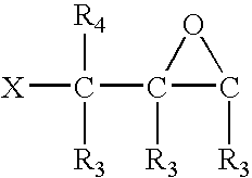
N(R3)H 
Sulfonyl halide SO2—X HN(R3) N(R3)H X—SO2 Activated ester, CQOR5 HN(R3) DCCI coupling CQOR5 HO N(R3)H R5OCQ OH R5OCQ Urethane, (R3)NCQOR3 HN(R3) isocyanate, isothiocyanate N(R3)H R3OCQN(R3) N(R3)C═Q HN(R3) N(R3)H Q═CNR3 Alpha,beta- C(R3)(R4)═C(R3)(M) HN(R3) unsaturated carbonyl N(R3)H (M)(R3)C═C(R3)(R4) Anhydride 
HN(R3) 
HQ N(R3)H 
QH 
Diene Diels- -Alder Alder- -Diels C(R3)(R4)═C(R3)(R4) HNR3 C(R3)(R4)═C(R3)(R4) HQ NR3H C(R3)(R4)═C(R3)(R4) QH C(R3)(R4)═C(R3)(R4) Thiol SH HS Cyclopentadiene cyclopentadienyl [Me] + cyclopentadienyl - wherein R3 and R4 are independently H, normal or branched chain alkyl, normal or branched chain alkylene, cycloalkyl, aryl, or aralkyl, wherein R3 and R4, each independently comprise between 1 and 20 C atoms;
- where R5 is H (in the presence of a coupling agent such as dicyclohexylcarbodiimide), pentachlorophenyl or N-hydroxysuccinimidyl;
- wherein Q is O or S;
- wherein M is COOH, COOR3, CHO, CN, CON(R3)(R4), NO2, SOR3, or SO2R3;
- wherein [Me] designates any metal cation that forms a metallocene complex;
- X is F, Cl, Br, or I;
- Diels designates any conjugated diene that can combine with an ethylenic moiety to form a Diels-Alder adduct;
- Alder designates any ethylenic moiety that can combine with a conjugated diene to form a Diels-Alder adduct; and
- cyclopentadienyl refers to any monocyclic or polycyclic cyclopentadienyl radical.
- In general an encoded reagent-bearing article of the invention is prepared by
-
- a) providing an optical substrate having at least one surface, the substrate comprising an optical coding element providing an output signal corresponding to a code embedded in the coding element when the coding element is illuminated with incident radiation; and
- b) binding the reagent to a surface of the optical substrate.
When the code embedded in the particle is identified, and a single known reagent is bound to the surface, the coded particle is identified as bearing the known reagent.
- Three generic components comprising a reagent-bearing article are identified in
FIG. 40 and in several embodiments of the present invention, namely, the optical substrate, the linker, and the reagent-bearing moiety. The optical substrate and the reactive precursors of the linker and the reagent-bearing moiety may be reacted with each other in any suitable order to prepare the reagent-bearing article. In some embodiments of synthesizing the article, the linker precursor and the precursor of the reagent-bearing moiety may be combined first to prepare a linker-reagent moiety conjugate (seeFIG. 41 , panel a)). The latter, which still bears a reactive group ALP suitable for combining with a surface of the optical substrate, is then combined with the substrate to form a reagent-bearing article of the invention, as shown inFIG. 41 , panel b). - Alternatively, the optical substrate may be combined first with a reactive linker precursor to bind the linker to the substrate (see
FIG. 42 , panel a)). The bound linker is then contacted with a reactive precursor of the reagent-bearing moiety, yielding the final product, a reagent-bearing article of the invention as depicted inFIG. 42 , panel b). - Certain embodiments of bifunctional linker precursors are illustrated by way of nonlimiting example in
FIG. 43 , in the proximity of a silica surface. Each precursor may react with the substrate via one or more of its ethoxy groups. Then the second functionality, namely an aldehyde, an epoxide, or an amine, is available to react further with a spacer precursor or directly with a reagent or reagent precursor. - In the preparative reactions described above, the linker precursor employed may be generically described as having the structure
ALP-RL—YLP; - wherein the ALP moiety comprises an activated reagent that forms a covalent bond with the substrate;
- wherein, in significant embodiments, RL comprises (D)n,
-
- wherein each D moiety is independently a heteroatom, a carbonyl group, a C(R1)(R2) group, a C(R1)══ group, a saccharide residue, an amino acyl residue, a modified amino acyl residue, a nucleotidyl group, or a modified nucleotidyl group;
- wherein any one or more D moieties may bind a YLP moiety;
- wherein n represents the degree of multiplicity of inclusion of D and varies from 0 to 3000;
- wherein YLP is a reactive moiety, such as described previously in nonlimiting examples in Table 2, that forms a covalent bond with the reagent precursor;
- wherein each R1 and R2 is independently H, OH, normal or branched chain alkyl, normal or branched chain alkylene, cycloalkyl, aryl, normal or branched chain alkoxy, cycloalkoxy, aryloxy, normal or branched chain alkylamino, normal or branched chain alkyleneamino, cycloalkylamino or arylamino; and
- wherein R1, and R2 each independently comprise between 0 and 20 C atoms.
- In certain embodiments of the linker precursor, RL may have more than one D moiety terminating in a YLP moiety, thus permitting one linker to bind more than one reagent-bearing moiety (see
FIG. 39 , panel b, for an embodiment in which a linker binds two YL moieties). In addition, a trifunctional linker precursor including two YLP moieties may be created by including a D moiety having a branched structure and binding YLP moieties to branches within the D grouping. Additionally, YLP may include a dendrimer structure such that YLP binds to RL with a single valence, but terminates in a plurality of combining groups that react with YSP. A dendrimer terminus to YLP affords the option of binding a plurality of reagents to a single site on the particle. Thus, a dendrimeric embodiment of YLP may terminate in two combining groups, or three combining groups, or even more. - The reactive moiety ALP may comprise a moiety T when the surface of the optical substrate is a polymer, resin, or plastic. T may comprise HQ, HS—S, X-QC, X—NR3-CQ, X—CQ-O, X—CQ-NR3, HN═N, X—SO2—NR3, or X—NR3—SO2. Alternatively, ALP may comprise a moiety T or a Z-Si(RA)(RB) moiety when the substrate is a silica, a silicate, or a glass, wherein Z may comprise RC. In these various representations of T and Z-Si(RA)(RB),
- RA, RB, and RC are independently X, Z, OR3, or NR3R3;
-
- wherein R3 is H, normal or branched chain alkyl, normal or branched chain alkylene, cycloalkyl, aryl, or aralkyl,
- wherein R3 comprises between 0 and 20 C atoms;
- wherein X is F, Cl, Br, or I; and
- Q is O or S.
- In the reactions employed in preparing a reagent-bearing article, the precursor of the reagent moiety may described as
—YSP—RS-TR; - wherein YSP is a grouping that reacts with the linker precursor, and RS is a spacer. YSP is a reactive moiety, such as described previously in nonlimiting examples in Table 2, that forms a covalent bond with the linker precursor.
- In many advantageous embodiments of the reagent-bearing moiety, the RS component is constituted of (D)n,
-
- wherein each D moiety is independently a heteroatom, a carbonyl group, a C(R1)(R2) group, a C(R1)══ group, a saccharide residue, an amino acyl residue, a modified amino acyl residue, a nucleotidyl group, or a modified nucleotidyl group;
- wherein n represents the degree of multiplicity of inclusion of D and varies from 0 to 3000; and
- wherein each R1 and R2 is independently H, OH, normal or branched chain alkyl, normal or branched chain alkylene, cycloalkyl, aryl, normal or branched chain alkoxy, cycloalkoxy, aryloxy, normal or branched chain alkylamino, normal or branched chain alkyleneamino, cycloalkylamino or arylamino; and
- wherein R1, and R2 each independently comprise between 0 and 20 C atoms.
- Preparation of Coded Reagent Libraries
- A coded reagent library is constituted of a plurality of multicomponent articles wherein the articles have differing reagents bound to them. Such a coded reagent library may be prepared, for each article in the collection of articles, generally by a method including
-
- a) providing a diffraction grating-based encoded element, wherein the encoded element includes
- i) an optical substrate having at least one surface, and
- ii) an optical coding element comprising at least one diffraction grating disposed therein, said grating having at least one refractive index pitch superimposed at a common location effective to provide an optical code therein, the grating providing an output optical signal when illuminated by an incident light signal, said optical output signal being indicative of the code in said coding element; and
- b) binding a reagent to a surface of each of said optical substrates, thus preparing each member of a coded reagent library.
In more particular aspects, a coded reagent library is prepared by including the following additional detailed steps: - a′) in step a) above maintaining a first optical substrate bearing a first code separate from a second substrate bearing a second code, and
- b′) in step b) above binding a first reagent to the first optical substrate and a second reagent to the second optical substrate.
- a) providing a diffraction grating-based encoded element, wherein the encoded element includes
- Particle-Linker Composition
- An optical substrate may be bound with a linker precursor only, to form a particle-linker composition. Such a composition has altered properties in terms of buoyancy, fluid dynamics, and so forth, so that it may be employed to advantage to affect behavior in fluid and flowing suspensions.
- The Reagent
- The reagent TR may be any chemical substance useful in a process, assay, or reaction to which the reagent-bearing article of the invention may be applied. In many important embodiments of the invention, a reagent may include a nucleic acid, a polynucleotide, an oligonucleotide, a nucleotide, a nucleoside, a protein nucleic acid, a peptide nucleic acid, a protein or fragment thereof, an enzyme or fragment thereof, a receptor or fragment thereof, a polypeptide, an oligopeptide, an amino acid, a derivative of any of the foregoing, a modification of any of the foregoing, a synthetic organic molecule, a synthetic intermediate, a synthetic precursor, an antibiotic, a metabolite, any biochemical moiety, a candidate pharmaceutical agent, a pharmaceutical agent, a virus particle or a portion thereof, a prokaryotic cell, a eukaryotic cell, a vertebrate cell, a mammalian cell, a human cell, any portion of said cell, a liposome, a vesicle, and a subcellular organelle.
- Polynucleotides
- As used herein the terms “nucleic acid” and “polynucleotide” are considered synonymous with each other, and are used as conventionally understood by workers of skill in fields such as biochemistry, molecular biology, genomics, and similar fields related to the field of the invention. A polynucleotide employed in the invention may be single stranded or a base paired double stranded structure, or even a triple stranded base paired structure. A polynucleotide may be a DNA, an RNA, or any mixture or combination of a DNA strand and an RNA strand, such as, by way of nonlimiting example, a DNA-RNA duplex structure. A polynucleotide and “oligonucleotide” as used herein are identical in any and all attributes defined here for a polynucleotide except for the length of a strand. As used herein, a polynucleotide may be about 50 nucleotides or base pairs in length or longer, or about 60, or about 70, or about 80, or about 100, or about 150, or about 200, or about 300 nucleotides or base pairs or even longer. An oligonucleotide may be at least 3 nucleotides or base pairs in length, and may be shorter than about 70, or about 60, or about 50, or about 40, or about 30, or about 20, or about 15 nucleotides or base pairs in length.
- A “nucleoside” is conventionally understood by workers of skill in fields such as biochemistry, molecular biology, genomics, and similar fields related to the field of the invention as comprising a monosaccharide linked in glycosidic linkage to a purine or pyrimidine base; and a “nucleotide” comprises a nucleoside with at least one phosphate group appended, typically at a 3′ or a 5′ position (for pentoses) of the saccharide, but may be at other positions of the saccharide. Nucleotide residues occupy sequential positions in an oligonucleotide or a polynucleotide. Accordingly a modification or derivative of a nucleotide may occur at any sequential position in an oligonucleotide or a polynucleotide. All modified or derivatized oligonucleotides and polynucleotides are encompassed within the invention and fall within the scope of the claims. Modifications or derivatives can occur in the phosphate group, the monosaccharide or the base.
- By way of nonlimiting examples, the following descriptions provide certain modified or derivatized nucleotides. The phosphate group may be modified to a thiophosphate or a phosphonate. The phosphate may also be derivatized to include an additional esterified group to form a triester. The monosaccharide may be modified by being, for example, a pentose or a hexose other than a ribose or a deoxyribose. The monosaccharide may also be modified by substituting hydryoxyl groups with hydro or amino groups, by esterifying additional hydroxyl groups, and so on.
- The base may be modified in many ways; several modified bases occur naturally in various nucleic acids, and other modifications may mimic or resemble such naturally occurring modified bases. Nonlimiting examples of modified or derivatized bases include 5-fluorouracil, 5-bromouracil, 5-chlorouracil, 5-iodouracil, hypoxanthine, xanthine, 4-acetylcytosine, 5-(carboxyhydroxylmethyl)uracil, 5-carboxymethylaminomethyl-2-thiouridine, 5-carboxymethylaminomethyluracil, dihydrouracil, beta-D-galactosylqueosine, inosine, N6-isopentenyladenine, 1-methylguanine, 1-methylinosine, 2,2-dimethylguanine, 2-methyladenine, 2-methylguanine, 3-methylcytosine, 5-methylcytosine, N6-adenine, 7-methylguanine, 5-methylaminomethyluracil, 5-methoxyaminomethyl-2-thiouracil, beta-D-mannosylqueosine, 5′-methoxycarboxymethyluracil, 5-methoxyuracil, 2-methylthio-N6-isopentenyladenine, uracil-5-oxyacetic acid (v), wybutoxosine, pseudouracil, queosine, 2-ihiocytosine, 5-methyl-2-thiouracil, 2-thiouracil, 4-thiouracil, 5-methyluracil, uracil-5-oxyacetic acid methylester, uracil-5-oxyacetic acid (v), 5-methyl-2-thiouracil, 3-(3-amino-3-N-2-carboxypropyl) uracil, (acp3)w, and 2,6-diaminopurine.
- Nucleotides may also be modified to harbor a label. Nucleotides bearing a fluorescent label or a biotin label, for example, are available from Sigma (St. Louis, Mo.).
- A significant use of a nucleic acid-, polynucleotide-, or oligonucleotide-bearing reagent-bearing article is in assay directed to identifying a target sequene to which the probe hybridizes. The selectivity of a probe for a target is affected by the stringency of the hybridizing conditions. “Stringency” of hybridization reactions is readily determinable by one of ordinary skill in the art, and generally is an empirical calculation dependent upon probe length, washing temperature, and salt concentration. In general, longer probes require higher temperatures for proper annealing, while shorter probes need lower temperatures. Hybridization generally depends on the ability of denatured DNA to reanneal when complementary strands are present in an environment below their melting temperature. The higher the degree of desired homology between the probe and hybridizable sequence, the higher the relative temperature which can be used. As a result, it follows that higher relative temperatures would tend to make the reaction conditions more stringent, while lower temperatures less so. For additional details and explanation of stringency of hybridization reactions, see Ausubel et al., Current Protocols in Molecular Biology, Wiley Interscience Publishers, (1995).
- Nonlimiting examples of “stringent conditions” or “high stringency conditions”, as defined herein, include those that: (1) employ low ionic strength and high temperature for washing, for example 0.015 M sodium chloride/0.0015 M sodium citrate/0.1% sodium dodecyl sulfate at 50° C.; (2) employ during hybridization a denaturing agent, such as formamide, for example, 50% (v/v) formamide with 0.1% bovine serum albumin/0.1% Ficoll/0.1% polyvinylpyrrolidone/50 mM sodium phosphate buffer at pH 6.5 with 750 mM sodium chloride, 75 mM sodium citrate at 42° C.; or (3) employ 50% formamide, 5×SSC (0.75 M NaCl, 0.075 M sodium citrate), 50 mM sodium phosphate (pH 6.8), 0.1% sodium pyrophosphate, 5× Denhardt's solution, sonicated salmon sperm DNA (50 μg/ml), 0.1% SDS, and 10% dextran sulfate at 42° C., with washes at 42° C. in 0.2×SSC (sodium chloride/sodium citrate) and 50% formamide at 55° C., followed by a high-stringency wash consisting of 0.1×SSC containing EDTA at 55° C.
- “Moderately stringent conditions” may be identified as described by Sambrook et al., Molecular Cloning: A Laboratory Manual, New York: Cold Spring Harbor Press, 1989, and include the use of washing solution and hybridization conditions (e.g., temperature, ionic strength and % SDS) less stringent that those described above. An example of moderately stringent conditions is overnight incubation at 37° C. in a solution comprising:20% formamide, 5×SSC (150 mM NaCl, 15 mM trisodium citrate), 50 mM sodium phosphate (pH 7.6), 5× Denhardt's solution, 10% dextran sulfate, and 20 mg/ml denatured sheared salmon sperm DNA, followed by washing the filters in 1×SSC at about 37-50° C. The skilled artisan will recognize how to adjust the temperature, ionic strength, etc. as necessary to accommodate factors such as probe length and the like.
- High stringency conditions promote high selectivity in the hybridization of a probe to a target. Stringency conditions may be modified or adjusted by a worker of skill in the art to adapt hybridization conditions to use in high throughput or multiplexed assay systems (Ausubel et al.). In addition, in high throughput or multiplexed assay systems, both the probe characteristics and the stringency may be optimized to permit achieving the objectives of the multiplexed assay under a single set of stringency conditions.
- Protein Nucleic Acids
- As used herein, the terms “protein nucleic acids”, “peptide nucleic acids”, or “PNAs” refer to nucleic acid mimics, e.g., DNA mimics, in which the deoxyribose phosphate backbone is replaced by a pseudopeptide backbone and only the four natural nucleobases are retained. The neutral backbone of PNAs has been shown to allow for specific hybridization to DNA and RNA under conditions of low ionic strength. The synthesis of PNA oligomers can be performed using standard solid phase peptide synthesis protocols as described in Hyrup et al. (1996) above; Perry-O'Keefe et al. (1996) PNAS 93: 14670-675. A PNA can be incorporated into a reagent-bearing article as the reagent to serve as a probe in a diagnostic assay.
- Polypeptides and Proteins
- As used herein an “amino acid” designates any one of the naturally occurring alpha-amino acids that are found in proteins. In addition, the term “amino acid” designates any nonnaturally occurring amino acids known to workers of skill in protein chemistry, biochemistry, and other fields related to the present invention. These include, by way of nonlimiting example, sarcosine, hydroxyproline, norleucine, alloisoleucine, cyclohexylalanine, phenylglycine, homocysteine, dihydroxyphenylalanine, ornithine, citrulline, D-amino acid isomers of naturally occurring L-amino acids, and others.
- Additional examples of non-naturally occurring amino acids that may be substituted for a natural amino acid of a reagent peptide include the following alpha-amino acids: 2-aminobutyric acid, 2-amino-isobutyric acid, beta-alanine, beta-(4-biphenyl)-alanine, citrulline, diaminobutyric acid, homoarginine, homocysteine, 1-naphthylalanine, 2-naphthylalanine, norvaline, p-chlorophenylalanine, p-aminophenylalanine, p-fluorophenylalanine, p-nitrophenylalanine, 4-pyridylalanine, alpha,beta-diaminopropionic acid, cyclohexylalanine, norvaline, beta-(3-pyridinyl)alanine, 1-amino-1-cyclo-hexanecarboxylic acid, alpha-aminoisobutyric acid, 1-amino-1-cyclopropanecarboxylic acid, 1-amino-1-cyclobutanecarboxylic acid, 1-amino-1-cyclopentanecarboxylic acid, 1-amino-1-cyclohexanecarboxylic acid, 1-amino-1-cycloheptanecarboxylic acid, 1-amino-1-cyclooctanecarboxylic acid, and 1-amino-1-cyclononanecarboxylic acid. In addition, an alkyl or aryl residue in the preceding amino acids may contain 1-4 hydroxy substituents. Additional examples of amino acyl derivatives that may be incorporated into peptide reagent are disclosed in U.S. Pat. No. 6,841,657, incorporated herewith in its entirety.
- By way of nonlimiting example, a derivatized amino acid residue may further have the following side chains: ethyl, n-butyl, —CH2—CH2—OH, —CH2—CH2—CH2—OH, —CH2—CHOHCH3 and —CH2—S—CH3; phenylglycine; cyclohexylmethylalanine; modified amino residues having substituted benzyl or phenyl side chains wherein preferred substituents include one or more of the following: halogen, methyl, ethyl, nitro, methoxy, ethoxy and —CN; a substituted or unsubstituted aliphatic, aromatic or benzylic ester of glutamic or aspartic acid (e.g., methyl, ethyl, n-propyl iso-propyl, cyclohexyl, benzyl or substituted benzyl); CO—NH-alkylated glutamate or asparagine (e.g., methyl, ethyl, n-propyl and iso-propyl); and modified amino acids having the side chain —(CH2).3—COOH, an ester thereof (substituted or unsubstituted aliphatic, aromatic or benzylic ester), an amide thereof or a substituted or unsubstituted N-alkylated amide thereof; N-nitroarginine; beta-cycloarginine; gamma-hydroxyarginine; N-amidinocitruline; 2-amino-4-guanidinobutanoic acid; homologs of lysine; homologs of arginine; and modified amino acids having C1-C5 straight or branched alkyl side chains substituted with —OH or —SH.
- In addition an amino acid may be modified or derivatized, for example by coupling the side chain with a label. Any amino acid known to a worker of skill in the art may be used as a reagent in a reagent-bearing article of the present invention.
- Amino acid residues are constituents of oligopeptides, polypeptides and proteins. As used herein an “oligopeptide” or “peptide” may be at least 3 amino acid residues in length, and may be shorter than about 70, or about 60, or about 50, or about 40, or about 30, or about 20, or about 15, or about 10 amino acid residues in length. Many peptides are of direct interest, since a number of biologically active substances are relatively short peptides. In addition, amino acid sequences identified as serving as motifs or domains are relatively short. These and a wide range of other peptides or oligopeptides may serve as reagents in a reagent-bearing article of the invention.
- As used herein a “polypeptide” or a “protein” may be considered to have a chain length of at least 50 amino acid residues, and may have as many as about 100, or about 150, or about 200, or about 300, or about 400, or about 500, or about 700, or about 1000 or more amino acids in the molecule. A protein is generally considered to be a composition that occurs naturally and may be isolated from a natural source. As such a protein may also have other characteristics. By way of nonlimiting example, a protein may additionally be a complex between two or more individual polypeptide chains held together by noncovalent interactions and/or by covalent bonds. A protein may additionally be a mature form of a polypeptide chain that is the gene product of an mRNA arising from a gene.
- As used herein, a “mature” form of a polypeptide or protein disclosed in the present invention is the product of a naturally occurring polypeptide or precursor form or proprotein. The naturally occurring polypeptide, precursor or proprotein includes, by way of nonlimiting example, the full length gene product, encoded by the corresponding gene. Alternatively, it may be defined as the polypeptide, precursor or proprotein encoded by an open reading frame described herein. The product “mature” form arises, again by way of nonlimiting example, as a result of one or more naturally occurring processing steps as they may take place within the cell, or host cell, in which the gene product arises. Examples of such processing steps leading to a “mature” form of a polypeptide or protein include the cleavage of the N-terminal methionine residue encoded by the initiation codon of an open reading frame, or the proteolytic cleavage of a signal peptide or leader sequence. Thus a mature form arising from a precursor polypeptide or protein that has
residues 1 to N, whereresidue 1 is the N-terminal methionine, would haveresidues 2 through N remaining after removal of the N-terminal methionine. Alternatively, a mature form arising from a precursor polypeptide orprotein having residues 1 to N, in which an N-terminal signal sequence fromresidue 1 to residue M is cleaved, would have the residues from residue M+1 to residue N remaining. Further as used herein, a “mature” form of a polypeptide or protein may arise from a step of post-translational modification other than a proteolytic cleavage event. Such additional processes include, by way of non-limiting example, glycosylation, myristoylation or phosphorylation. In general, a mature polypeptide or protein may result from the operation of only one of these processes, or a combination of any of them. - A protein, polypeptide, oligopeptide or peptide may be modified by introducing one or more amino acid substitutions such that the amino acid sequence of the resulting product differs from the sequence that occurs in the naturally occurring substance.
- Proteins have a wide range of functions and activities in biological organisms. Important examples of proteins include, by way of nonlimiting example, enzymes, receptors, and antibodies. Enzymes are reagents of interest in the present invention, since certain enzymes may be implicated, for example, in various pathological conditions. In such cases, it may be of interest to detect the presence of a substrate in a target sample, or to identify inhibitors from a set of candidates in a target sample. Likewise a receptor may be a reagent of interest, since binding of a specific ligand to a receptor as an agonist typically induces a signaling cascade leading to downstream sequellae in a cell. Many pathological states result from inappropriate receptor signaling. A receptor as a reagent bound to a particle may also be used to identify a therapeutic antagonist in a target composition to which it is exposed.
- A reagent of the present invention may be any one of an amino acid, a peptide, an oligopeptide, a polypeptide, a protein, a receptor, an enzyme, or an antibody.
- Antibodies
- An antibody may be used as a probe to detect its cognate antigen in a target composition. For this reason antibodies are also an important class of reagent in a reagent-bearing article of the present invention. The term “antibody” as used herein refers to immunoglobulin molecules and immunologically active portions of immunoglobulin (Ig) molecules, i.e., molecules that contain an antigen binding site that specifically binds (immunoreacts with) an antigen. Such antibodies include, but are not limited to, polyclonal, monoclonal, chimeric, single chain, Fab, Fab′ and F(ab′)2 fragments, and an Fab expression library. In general, antibody molecules obtained from humans relates to any of the classes IgG, IgM, IgA, IgE and IgD, which differ from one another by the nature of the heavy chain present in the molecule. Certain classes have subclasses as well, such as IgG1, Ig2, and others. Furthermore, in humans, the light chain may be a kappa chain or a lambda chain. Reference herein to antibodies includes a reference to all such classes, subclasses and types of human antibody species. Any antibody disclosed herein binds “immunospecifically” to its cognate antigen. By immunospecific binding is meant that an antibody raised by challenging a host with a particular immunogen binds to a molecule such as an antigen that includes the immunogenic moiety with a high affinity, and binds with only a weak affinity or not at all to non-immunogen-containing molecules. As used in this definition, high affinity means having a dissociation constant less than about 1 μM, and weak affinity means having a dissociation constant higher than about 1 μM.
- An isolated protein of the invention intended to serve as an antigen, or a portion or fragment thereof, can be used as an immunogen to generate antibodies that immunospecifically bind the antigen, using standard techniques for polyclonal and monoclonal antibody preparation. The full-length protein can be used or, alternatively, antigenic peptide fragments of the antigen may be used as immunogens. An antigenic peptide fragment comprises at least 6, or at least 10, or at least 15 amino acid residues of the amino acid sequence of the full length protein, and encompasses an epitope thereof such that an antibody raised against the peptide forms a specific immune complex with the full length protein or with any fragment that contains the epitope. Antibodies that are specific for one or more domains within an antigenic protein, or derivatives, fragments, analogs or homologs thereof, may also be used as a reagent of the invention. A protein of the invention, or a derivative, fragment, analog, homolog or ortholog thereof, may be utilized as an immunogen in,the generation of antibodies that immunospecifically bind these protein components.
- Various procedures known within the art may be used for the production of polyclonal or monoclonal antibodies directed against a protein of the invention, or against derivatives, fragments, analogs homologs or orthologs thereof (see, for example, Antibodies: A Laboratory Manual, Harlow E, and Lane D, 1988; Cold Spring Harbor Laboratory Press, Cold Spring Harbor, N.Y., incorporated herein by reference). Some of these antibodies are discussed below.
- 1. Polyclonal Antibodies
- For the production of polyclonal antibodies, various suitable host animals (e.g., rabbit, goat, mouse or other mammal) may be immunized by one or more injections with the native protein, a synthetic variant thereof, or a derivative of the foregoing. An appropriate immunogenic preparation can contain, for example, the naturally occurring immunogenic protein, a chemically synthesized polypeptide representing the immunogenic protein, or a recombinantly expressed immunogenic protein. Furthermore, the protein may be conjugated to a second protein known to be immunogenic in the mammal being immunized. Examples of such immunogenic proteins include but are not limited to keyhole limpet hemocyanin, serum albumin, bovine thyroglobulin, and soybean trypsin inhibitor.
- The polyclonal antibody molecules directed against the immunogenic protein can be isolated from the mammal (e.g., from the blood) and further purified by well known techniques, such as affinity chromatography using protein A or protein G, which provide primarily the IgG fraction of immune serum. Subsequently, or alternatively, the specific antigen which is the target of the immunoglobulin sought, or an epitope thereof, may be immobilized on a column to purify the immune specific antibody by immunoaffinity chromatography. Purification of immunoglobulins is discussed, for example, by D. Wilkinson (The Scientist, published by The Scientist, Inc., Philadelphia Pa., Vol. 14, No. 8 (Apr. 17, 2000), pp. 25-28).
- 2. Monoclonal Antibodies
- The term “monoclonal antibody” (MAb) as used herein, refers to a population of antibody molecules that contain only one molecular species of antibody molecule consisting of a unique light chain gene product and a unique heavy chain gene product. In particular, the complementarity determining regions (CDRs) of the monoclonal antibody are identical in all the molecules of the population. MAbs thus contain an antigen binding site capable of immunoreacting with a particular epitope of the antigen characterized by a unique binding affinity for it.
- Monoclonal antibodies can be prepared using hybridoma methods, such as those described by Kohler and Milstein, Nature, 256:495 (1975 (See also Goding, Monoclonal Antibodies: Principles and Practice, Academic Press, (1986) pp. 59-103)). In a hybridoma method, a mouse, hamster, or other appropriate host animal, is typically immunized with an immunizing agent to elicit lymphocytes that produce or are capable of producing antibodies that will specifically bind to the immunizing agent. Alternatively, the lymphocytes can be immunized in vitro.
- The monoclonal antibodies can also be made by recombinant DNA methods, such as those described in U.S. Pat. No. 4,816,567. DNA encoding the intended monoclonal antibodies can be readily isolated and sequenced using conventional procedures (e.g., by using oligonucleotide probes that are capable of binding specifically to genes encoding the heavy and light chains of murine antibodies). The hybridoma cells of the invention serve as a preferred source of such DNA. Once isolated, the DNA can be placed into expression vectors, which are then transfected into host cells such as simian COS cells, Chinese hamster ovary (CHO) cells, or myeloma cells that do not otherwise produce immunoglobulin protein, to obtain the synthesis of monoclonal antibodies in the recombinant host cells.
- 3. Humanized Antibodies
- The antibody reagents can further comprise humanized antibodies or human antibodies. Humanized forms of antibodies are chimeric immunoglobulins, immunoglobulin chains or fragments thereof (such as Fv, Fab, Fab′, F(ab′)2 or other antigen-binding subsequences of antibodies) that are principally comprised of the sequence of a human immunoglobulin, and contain minimal sequence derived from a non-human immunoglobulin. Humanization can be performed following the method of Winter and co-workers (Jones et al, Nature 321:522-525 (1986); Riechmann et al., Nature, 332:323-327 (1988); Verhoeyen et al., Science, 239:1534-1536 (1988)), by substituting rodent CDRs or CDR sequences for the corresponding sequences of a human antibody. (See also U.S. Pat. No. 5,225,539.)
- 4. Human Antibodies
- Fully human antibodies relate to antibody molecules in which the entire sequence of both the light chain and the heavy chain, including the CDRs, arise from human genes. Such antibodies are termed “human antibodies”, or “fully human antibodies” herein. Human monoclonal antibodies can be prepared by the trioma technique; the human B-cell hybridoma technique (see Kozbor, et al. (1983) Immunol Today 4: 72) and the EBV hybridoma technique to produce human monoclonal antibodies (see Cole, et al. (1985) In: MONOCLONAL ANTIBODIES AND CANCER THERAPY, Alan R. Liss, inc., pp. 77-96). Human monoclonal antibodies may be utilized in the practice of the present invention and may be produced by using human hybridomas (see Cote, et al. (1983) Proc Natl Acad Sci USA 80: 2026-2030) or by transforming human B-cells with Epstein Barr Virus in vitro (see Cole, et al. (1985) in: MONOCLONAL ANTIBODIES AND CANCER THERAPY, Alan R. Liss, Inc., pp. 77-96).
- In addition, human antibodies can also be produced using additional techniques, including phage display libraries (Hoogenboom and Winter (1991) J. Mol. Biol., 227:381; Marks et al. (1991) J. Mol. Biol., 222:581). Similarly, human antibodies can be made by introducing human immunoglobulin loci into transgenic animals e.g., mice in which the endogenous immunoglobulin genes have been partially or completely inactivated. Upon challenge, human antibody production is observed, which closely resembles that seen in humans in all respects, including gene rearrangement, assembly, and antibody repertoire. This approach is described, for example, in U.S. Pat. Nos. 5,545,807; 5,545,806; 5,569,825; 5,625,126; 5,633,425; 5,661,016, and in Marks et al. (1992) (Bio/
Technology 10, 779-783); Lonberg et al. ((1994) Nature 368 856-859); Morrison ((1994) Nature 368, 812-13); Fishwild et al, ((1996)Nature Biotechnology 14, 845-51); Neuberger ((1996)Nature Biotechnology 14, 826); and Lonberg and Huszar ((1995) Intern. Rev. Immunol. 13 65-93). - 5. Single Chain Antibodies and Fab Fragments
- Single-chain antibodies specific to an antigenic protein of interest can also be used as a reagent in the invention (see e.g., U.S. Pat. No. 4,946,778). In addition, construction of Fab expression libraries (see e.g., Huse, et al., 1989 Science 246: 1275-1281) allow rapid and effective identification of monoclonal Fab fragments with the desired specificity for a protein, or derivatives, fragments, analogs or homologs thereof.
- Any oligopeptide, polypeptide or protein that has been modified or derivatized may also serve as reagent in forming a reagent-bearing article of the invention. A common example of a derivatization is binding a label to an oligopeptide, polypeptide or protein. A label may be a luminescent label, or a reagent that is a member of a specific binding pair such as biotin, avidin, streptavidin, digoxin, digoxigenin, and the like. In addition an oligopeptide, polypeptide or protein may be chemically modified by any of a broad range of reagents such as those provided by Pierce Biotechnology, Inc., Rockford, Ill.
- Organic Molecules, Antibiotics, Metabolites, and Drugs
- Any of a broad range of synthetic organic molecules, antibiotics and their derivatives, metabolites, enzyme substrates and substrate analogs, enzyme inhibitors, chemical compounds that are members of a combinatorial library, other biochemical moieties, drug candidates and lead compounds, and the like, all may serve as reagents of the present invention. For example many antibiotics are currently known, and many more are being identified. An antibiotic may be used as a reagent of the invention in various assays and processes. Metabolomics is a growing field of investigation as one of the consequences of genomics studies. A metabolite, or a suspected or candidate metabolite, may be bound to a particle to facilitate investigational and diagnostic research concerning the role played by the metabolite. In addition, any enzyme substrate or substrate analog, or an enzyme inhibitor, or a candidate inhibitor in a screen of an inhibitor library, may be a reagent of the invention. Eukaryotic proteins contain many post-translational modifications, of which complex glycosidic substituents are very important. Synthetic libraries of complex saccharides may be bound as the reagents in the particles of the invention. Components of combinatorial libraries in general may be bound as reagents to particles of the invention as part of investigational studies directed toward identifying and optimizing a chemical substance for use as a pharmaceutical agent.
- Inorganic Molecules
- Any inorganic compound can be a reagent of the invention. An important example is an inorganic substance that is a catalyst. Other examples of inorganic reagents of the invention include nanoparticles (e.g. quantum dots), ceramic particles, semiconductor particles, and the like.
- Organelles, Viruses and Cells
- A reagent bound to coded particle of the invention may be a supramolecular construct, a subcellular particle, or a complete cell. For example, liposomes and lipid vesicles may be bound as reagents. Such constructs may include within the lumen or bound within the lipid membrane a reagent or molecule of interest for a particular application. Any subcellular particle may be bound to a coded particle, including, by way of nonlimiting example, microsomes, ribonucleoprotein particles, ribosomes, particles of endoplasmic reticulum, particles of Golgi apparatus, lysosomes, proteasomes, peroxisomes, mitochondria, and so forth. Additionally whole cells may be bound to a coded particle; including, by way of nonlimiting example, fibroblasts, hepatocytes, myocytes, erythrocytes, kidney cells, lymphocytes, macrophages, adipocytes, pancreatic islet cells, glial cells, dendroctyes, bacterial cells including any of a wide range of pathogens, and virus particles.
- Assay Compositions
- The invention includes assay compositions that contain a reagent particle of the invention and a fluid medium. Commonly the reagent particle is suspended in the fluid. In many applications of assay compositions, they may in addition contain an analyte in the fluid. The fluid may be any gaseous or liquid fluid, or a it may be a supercritical fluid. Commonly a fluid may be an aqueous liquid, such as a buffer optimized to carry out a particular assay.
- In addition, an assay composition may contain a reagent library that includes a plurality of reagent particles of the invention and a fluid medium. Such a composition may also have an analyte contained in the fluid.
- Chemical Synthesis Using Encoded Particles
- The encoded particles of the invention may be used to synthesize identifiable compounds. In many such applications the particular compound synthesized is identified by a digital code of the particle used as the substrate. In this way libraries are conveniently synthesized, wherein each member of the library is known by the digital code of the particle on which it has been prepared.
- In order to initiate the synthesis of a compound, an encoded reagent-bearing article is prepared having any reactant bound as the reagent. The reactant serves as one component in a synthetic chemical reaction, with one or more additional reactants provided in a liquid composition in which the particle is suspended. Contact of the reactant on the reagent-bearing article with the remaining reactant(s) in the composition under suitable reaction conditions provides a new chemical product synthesized on the particle. Nonbound reactants and side products are rinsed away from the particle. The new chemical product becomes the new reagent component of the reagent-bearing article, purified from all other substances involved in the reaction. Subsequently, any compound may be partially or totally synthesized on the substrate as intended.
- Peptides, oligopeptides and polypeptides may be prepared using an encoded optical element. Additionally oligonucleotides and polynucleotides may be synthesized. Complex carbohydrates, such as those bound to glycoproteins, and related complex oligosaccharide chains, may be synthetically elaborated on a reagent-bearing article of the invention. Organic and inorganic compounds may likewise be prepared using appropriate chemical synthetic steps.
- Peptides, oligopeptides and polypeptides may be synthesized using stepwise chain extension by well known techniques initially developed by B. Merrifield, and described, by way of nonlimiting example, in The Practice of Peptide Synthesis, 2nd Ed., M Bodanszky and A. Bodanszky, Springer-Verlag, New York, N.Y. (1994).
- In situ synthesis of oligonucleotide or polynucleotide probes on the substrate is performed in accordance with well-known chemical processes, including, but not limited to sequential addition of nucleotide phosphoramidites to surface-linked hydroxyl groups, as described by T. Brown and Dorcas J. S. Brown in Oligonucleotides and Analogues A Practical Approach, F. Eckstein, editor, Oxford University Press, Oxford, pp. 1-24 (1991), and incorporated herein by reference. Other methods of oligonucleotide synthesis include, but are not limited to solid-phase oligonucleotide synthesis according to the phosphotriester and phosphodiester methods (Narang, et al., (1979) Meth. Enzymol. 68:90), and to the H-phosphonate method (Garegg, P. J., et al., (1985) “Formation of internucleotidic bonds via phosphonate intermediates”,
Chem. Scripta 25, 280-282; and Froehler, B. C., et al., (1986a) “Synthesis of DNA via deoxynucleoside H-phosphonate intermediates”, Nucleic Acid Res., 14, 5399-5407, among others) and synthesis on a support (Beaucage, et al. (1981) Tetrahedron Letters 22:1859-1862) as well as phosphoramidate techniques (Caruthers, M. H., et al., “Methods in Enzymology,” Vol. 154, pp. 287-314 (1988), U.S. Pat. Nos. 5,153,319, 5,132,418, 4,500,707, 4,458,066, 4,973,679, 4,668,777, and 4,415,732, and others described in “Synthesis and Applications of DNA and RNA,” S. A. Narang, editor, Academic Press, New York, 1987, and the references contained therein, and nonphosphoramidite techniques. - In general terms a coded polynucleotide reagent article, or a coded polynucleotide reagent library, may be synthesized by the steps of:
-
- a) providing a one or more diffraction grating-based encoded elements, wherein each encoded element contains
- i) an optical substrate having at least one surface, and
- ii) an optical coding element comprising at least one diffraction grating disposed therein, the grating having at least one refractive index pitch superimposed at a common location effective to provide an optical code therein, the grating providing an output optical signal when illuminated by an incident light signal, the optical output signal being indicative of the code in the coding element;
- b) binding first nucleotide reagent to a surface of each of the one or more optical substrates; and
- c) extending the nucleotide sequence on each substrate by sequential addition reactions;
thereby synthesizing one polynucleotide, or a library of polynucleotides, respectively, bound to the articles.
In some greater detail, additional steps for synthesizing a polynucleotide library include - a′) in step a) above, maintaining a first optical substrate bearing a first code separate from a second substrate bearing a second code, and
- b′) in steps b) and c) above, synthesizing a first polynucleotide on the first optical substrate and a second polynucleotide on the second optical substrate
- a) providing a one or more diffraction grating-based encoded elements, wherein each encoded element contains
- In an alternative synthetic procedure for preparing a coded polynucleotide reagent article, or a coded polynucleotide reagent library, the following steps may be employed:
-
- a) providing a one or more diffraction grating-based encoded elements, wherein each encoded element includes
- i) an optical substrate having at least one surface, and
- ii) an optical coding element containing at least one diffraction grating disposed therein, the grating having at least one refractive index pitch superimposed at a common location effective to provide an optical code therein, the grating providing an output optical signal when illuminated by an incident light signal, the optical output signal being indicative of the code in the coding element; and
- b) binding a polynucleotide to a surface of each of the one or more optical substrates.
- a) providing a one or more diffraction grating-based encoded elements, wherein each encoded element includes
- Oligosaccharide components of biological macromolecules may be synthesized using the encoded reagent-bearing articles of the invention. There are very many ramified structures of complex carbohydrates that may be potentially synthesized. The coded particles of the invention are highly advantageous, therefore, in creating oligosaccharide libraries. Nonlimiting examples describing synthetic protocols available for oligosaccharide synthesis include Adinolfi, M., Barone, G., De Napoli, L., ladonisi, A., and Piccialli, G., Solid Phase Synthesis of Oligosaccharides, Tet. Lett.,1996, 37, 5007-5010; Seeberger, P. H., Haase, W.-C., Solid-Phase Oligosaccharide Synthesis and Combinatorial Carbohydrate Libraries, Chem. Rev. 2000, 100, 4349-4394; Plante, O. J., Palmacci, E. R., Seeberger, P. H., Automated Solid-Phase Synthesis of Oligosaccharides, Science 2001, 291, 1523-1527; and Plante, O. J., Palmacci, E. R., Andrade, R. B., Seeberger, P. H., Oligosaccharide Synthesis Using Glycosyl Phosphate and Dithiophosphate Triesters as Glycosylating Agents, J. Am. Chem. Soc. 2001, 123, 9545-9554.
- Since each particle is encoded, multiplexed chemical syntheses may be carried out simultaneously, providing a plurality of new chemical products bound to uniquely encoded particles. Thus each code corresponds uniquely to a particular chemical compound. High complexity combinatorial libraries may be prepared in this way using a large number of encoded reagent-bearing articles, including digitally encoded particles, of the invention. For example, a digitally encoded oligonucleotide library is synthesized by using a plurality of digitally encoded particles as substrates in the synthetic steps, and tracking each encoded particle as it proceeds through the various nucleotide addition steps. In this way, each particle bearing a unique digital code is identified as bearing an oligonucleotide having a particular sequence.
- Use of Reagent-Bearing Articles in Assays
- Referring to
FIGS. 3-8 , thesubstrate 10 of the diffraction grating-based encoded element (or microbead) 8 may be functionalized by coating or attaching a desiredprobe 76, such as a compound, chemical or molecule, which is then used in an assay as an attractant for certain complimentary compounds, chemicals or molecules, otherwise known as a “target” analyte 52-54 (seeFIG. 6 ). This capability to uniquely encode a large number ofmicrobeads 8 with a correspondingunique probe 76 attached thereto enables these functionalizedmicrobeads 72 to be mixed with unknown “target” analytes 52-54 to perform a multiplexed experiment. Theprocedure 40 for performing such a multiplexed assay or experiment includes the steps of producing (step 42) themicrobead 8, as described hereinbefore, and functionalizing (step 44) thesubstrate 10 of themicrobead 8 by coating/depositing/growing it with aprobe 76 that will react in a predetermined way with “target” analytes 52-54. An assay is then performed (step 46) with a plurality offunctionalized microbeads 72 withdifferent identification codes 58 at the same time. Instep 48, the fluorescence of the functionalizedmicrobeads 72 is analyzed, and thefunctionalized microbead 72 is read to determine thecode 58 thereof to thereby determine which “target” analytes 5-54 are present in thesolution 60. - In
FIGS. 4 and 5 , afunctionalized microbead 72 is shown, wherein thesubstrate 10 of themicrobead 8 is coated with aprobe 76 and used in an assay or as an attractant for certain “target” analytes 52-54 (seeFIG. 6 ). In one embodiment shown inFIG. 4 , themicrobead 8 is coated with a linker molecule or complex 62 as is known in the art. Amolecular group 64 is attached to theprobe 76 to enable the probe to be bonded to the linker molecule or complex 62, and thus to themicrobead 8 to form thefunctionalized microbead 72. Theprobe 76 may include one of an Oligonucleotides (oligos), antibodies, peptides, amino acid strings, cDNA, RNA, chemicals, nucleic acid oligomers, polymers, biological cells, or proteins. For example, theprobe 76 may comprise a single strand of DNA (or portion thereof) and the “target” analyte 52-54 comprises at least one unknown single strand of DNA, wherein each different “target” analyte has a different DNA sequence. - In some instances as shown in
FIG. 5 , theprobe 76 may be attached directly to thesubstrate 10 of themicrobead 8, or directly synthesized (or grown) thereon, such as via phosphoramidite chemistry. Examples of surface chemistry for thefunctionalized microbeads 72 include Streptavidin/biotinylated oligos and Aldehyde/amine modified oligos. Further, the microbead may be coated with a blocker of non-specific binding (e.g., salmon sperm DNA) to prevent bonding of analytes 52-54 (e.g. DNA) to thenon-functionalized surface 66 of the functionalizedmicrobeads 72. - Referring to
FIG. 6 , an assay is performed by adding asolution 60 of different types of “target” analytes 52-54 into a cell orcontainer 70 having a plurality of functionalized microbeads 72-74 disposed therein. As discussed instep 46 ofFIG. 3 , the functionalized microbeads 72-74 placed in thecell 70 havedifferent identification codes 58 that correspond to unique probes 76-78 bonded thereto. For example, all functionalizedmicrobeads 72 disposed within thecell 70 having an identification code of 12345678 is coated with aunique probe 76. Allfunctionalized microbeads 73 disposed within thecell 72 having an identification code of 34128913 is coated with aunique probe 77. Allfunctionalized microbeads 77 disposed within thecell 70 having an identification code of 11778154 is coated with aunique probe 78. - The “target” analytes 52-54 within the
solution 60 are then mixed with the functionalized microbeads 72-74. During the mixing of the “target” analytes 52-54 and the functionalized microbeads 72-74, the “target” analytes attach to the complementary probes 76-78, as shown for functionalizedmicrobeads codes FIG. 6 , “target”analytes 53 bonded withprobes 76 of the functionalizedmicrobeads 72 having thecode 12345678, and “target”analytes 52 bonded withprobes 77 of the functionalizedmicrobeads 73 having thecode 34128913. On the other hand, “target”analytes 54 did not bond with any probes, and not “target” analytes 52-54 in thesolution 60 bonded withprobes 78 of the functionalizedmicrobeads 74 having thecode 11778154. Consequently, knowing which “target” analytes attach to which probes along with the capability of identifying each probe by the encoded microbead, the results of the assay would show that the unknown “target” analytes in thesolution 60 includes “target”analytes - For example as discussed hereinbefore, each coded functionalized microbead 72-74 has a unique probe 76-78, respectively bonded thereto, such as a portion of a single strand of DNA. Similarly, the “target” analytes 52-54 comprise a plurality of unknown and unique single strands of DNA. These “target” analytes 52-54 are also processed with a fluorescent, such as dyeing, such that the test molecules illuminate. As will be discussed hereinafter, the fluorescence of the “target” analytes provide the means to identify, which functionalized microbeads 72-74 have a “target” analyte attached thereto.
- Once the reaction or combining is complete, the functionalized microbeads 72-74 are rinsed off with a saline solution to clean off the uncombined “target” analytes 52-54. As shown in
FIG. 7 , the functionalized microbeads 72-74 may be placed in atray 84 withgrooves 82 to allow the functionalized microbeads to be aligned in a predetermined direction, such as that described in U.S. patent application Ser. No. (Cidra Docket No. CC-0648), filed contemporaneously, which is incorporated herein by reference. Thegrooves 82 may have holes (not shown) that provide suction to keep the functionalized microbeads in position. Once aligned in thetray 84, the functionalized microbeads 52-54 are individually scanned and analyzed by thebead detector 20. - As best shown in
FIG. 8 , each functionalized microbead 72-74 is detected for fluorescence and analyzed to determine theidentification code 58 of the functionalized microbeads. A light source (not shown) may be provided to luminate the microbeads 72-74. Once the fluorescent microbeads 72-74 are identified and knowing which probe 76-78 (or single strand of DNA) was attached to each coded, functionalized microbead 72-74, thebead detector 20 determines which “target” analytes 52-54 were present in thesolution 60. As described hereinbefore, thebead detector 20 illuminates the functionalized microbeads 72-74 and focuses light 26 reflected by thediffraction grating 12 onto a CCD array orcamera 32, whereby thecode 58 of the functionalized microbead 72-74 is determined. Secondly, thebead detector 20 includes afluorescence detector 86 for measuring the fluorescence emanating from “target” analytes 52-54 attached to the probes 76-78. Thefluorescence meter 86 includes alens 88 andoptical fiber 90 for receiving and providing the fluorescence from the “target” analyte 52-54 to the fluorescence meter. - Referring to
FIG. 9 , more specifically, the codes in themicrobeads 8 are detected when illuminated by incident light 24 which produces a diffracted or outputlight signal 27 to areader 820, which includes the optics and electronics necessary to read the codes in eachbead 8, as described herein and/or in the aforementioned copending patent application. Thereader 820 provides a signal on aline 822 indicative of the code in each of thebead 8. Theincident light 24 may be directed transversely from the side of the tray 84 (or from an end or any other angle) with a narrow band (single wavelength) and/or multiple wavelength source, in which case the code is represented by a spatial distribution of light and/or a wavelength spectrum, respectively, as described hereinafter and in the aforementioned copending patent application. Other illumination, readout techniques, types of gratings, geometries, materials, etc. may be used for themicrobeads 8, as discussed hereinafter and in the aforementioned patent application. - For assays that use fluorescent molecule markers to label or tag chemicals, an
optical excitation signal 800 is incident on themicrobeads 8 through thetray 84 and a fluorescent optical output signal 802 emanates from thebeads 8 that have the fluorescent molecule attached. The fluorescent optical output signal 802 passes through alens 804, which provides focused light 802 to a knownoptical fluorescence detector 808. Instead of or in addition to the lens 802, other imaging optics may be used to provide the desired characteristics of the optical image/signal onto thefluorescence detector 808. Thedetector 808 provides an output signal on aline 810 indicative of the amount of fluorescence on a givenbead 8, which can then be interpreted to determine what type of chemical is attached to thebead 10. - The
tray 84 is made of glass or plastic or any material that is transparent to the codereading incident beam 24 and code reading output light beams 27 as well as thefluorescent excitation beam 800 and the output fluorescent optical signal 802, and is properly suited for the desired application or experiment, e.g., temperature range, harsh chemicals, or other application specific requirements. - The
code signal 822 from thebead code reader 820 and thefluorescent signal 810 from the fluorescence detector are provided to a knowncomputer 812. The computer reads the code associated with each bead and determines the chemical probe that was attached thereto from a predetermined table that correlates a predetermined relationship between the bead code and the attached probed. In addition, thecomputer 812 and reads the fluorescence associated with each bead and determines the sample or analyte that is attached to the bead from a predetermined table that correlates a predetermined relationship between the fluorescence tag and the analyte attached thereto. Thecomputer 812 then determines information about the analyte and/or the probe as well as about the bonding of the analyte to the probe, and provides such information on a display, printout, storage medium or other interface to an operator, scientist or database for review and/or analysis. Thesources code reader 820, thefluorescence optics 804 anddetector 808 and thecomputer 812 may all be part of anassay stick reader 824. - Alternatively, instead of having the
code excitation source 801 and thefluorescence excitation source 803, thereader 24 may have only one source beam which provides both the reflectedoptical signal 27 for determining the code and the fluorescence signal 802 for reading the tagged analyte attached to thebeads 8. In that case the input optical signal is a common wavelength that performs both functions simultaneously, or sequentially, if desired. - Generally, the assay of the present invention may be used to carry out any binding assay or screen involving immobilization of one of the binding agents. Such solid-phase assays or screens are well known in the chemical and biochemical arts. For example, such screening may involve specific binding of cells to a molecule (e.g. an antibody or antigen) immobilized on a microbead in the assay stick followed by analysis to detect whether or to what extent binding occurs. Alternatively, the beads may subsequently removed from the assay stick for sorting and analysis via flow cytometry (see e.g. by Needels et al. (1993). Examples of biological compounds that may be assayed or screened using the assay stick of the present invention include, e.g. agonists and antagonists for cell membrane receptors, toxins, venoms, viral epitopes, hormones, sugars, cofactors, peptides, enzyme substrates, drugs inclusive of opiates and steroids, proteins including antibodies, monoclonal antibodies, antisera reactive with specific antigenic determinants, nucleic acids, lectins, polysaccharides, cellular membranes and organelles. In addition, the present invention may be used in any of a large number of well-known hybridization assays where nucleic acids are immobilized on a surface of a substrate, e.g. genotyping, polymorphism detection, gene expression analysis, fingerprinting, and other methods of DNA- or RNA-based sample analysis or diagnosis.
- Any of the great number of isotopic and non-isotopic labeling and detection methods well-known in the chemical and biochemical assay art may be used to detect binding with the present invention. Alternatively, spectroscopic methods well-known in the art may be used to determine directly whether a molecule is bound to a surface coating in a desired configuration. Spectroscopic methods include e.g., UV-VIS, NMR,EPR, IR, Raman, mass spectrometry and other methods well-known in the art. For example, mass spectrometry also is now widely employed for the analysis of biological macromolecules. The method typically involves immobilization of a protein on a surface of substrate where it is then exposed to a ligand binding interaction. Following ligand binding (or non-binding) the molecule is desorbed from the surface and into a spectrometer using a laser (see, e.g. Merchant and Weinberger, “Recent advancements in surface-enhanced laser desorption/ionization-time of flight-mass spectrometry,” Electrophoresis 21: 1164-1177 (2000)). The microbeads in the assay stick of the present invention may be used as substrates in the mass spectrometry detection methods described above.
- Various aspects of the present invention may be conducted in an automated or semi-automated manner, generally with the assistance of well-known data processing methods. Computer programs and other data processing methods well known in the art may be used to store information including e.g. microbead identifiers, probe sequence information, sample information, and binding signal intensities. Data processing methods well known in the art may be used to read input data covering the desired characteristics.
- The invention may be used in many areas such as drug discovery, functionalized substrates, biology, proteomics, combinatorial chemistry, DNA analysis/tracking/sorting/tagging, as well as tagging of molecules, biological particles, matrix support materials, immunoassays, receptor binding assays, scintillation proximity assays, radioactive or non-radioactive proximity assays, and other assays, (including fluorescent, mass spectroscopy), high throughput drug/genome screening, and/or massively parallel assay applications. The invention provides uniquely identifiable beads with reaction supports by active coatings for reaction tracking to perform multiplexed experiments.
- Some current techniques used in combinatorial chemistry or biochemistry are described in U.S. Pat. No. 6,294,327, entitled “Particle and Method for Detecting Samples Labeled With Material Having Strong Light Scattering Properties, Using Reflection Mode Light and Diffuse Scattering”, issued Sep. 23, 2001 to Walton et al.; U.S. Pat. No. 6,242,180, entitled “Computer Aided Visualization and Analysis System for Sequence Evaluation”, issued Jun. 5, 2001, to Chee; U.S. Pat. No. 6,309,823 entitled “Arrays of Nucleic Acid Probes for Analyzing Biotransformation of Genes and Methods of Using the Same”, Oct. 30, 2001, to Cronin et al.; U.S. Pat. No. 6,440,667, entitled “Analysis of Target Molecules Using an Encoding System”; U.S. Pat. No. 6,355,432, entitled “Products for Detecting Nucleic Acids”; U.S. Pat. No. 6,197,506, entitled “Method of Detecting Nucleic Acids”; U.S. Pat. No. 6,309,822, entitled “Method for comparing copy number of nucleic acid sequences”; U.S. Pat. No. 5,547,839, entitled “Sequencing of surface immobilized polymers utilizing micro-fluorescence detection”, U.S. Pat. No. 6,383,754, entitled “Binary Encoded Sequence Tags”, and U.S. Pat. No. 6,383,754, entitled “Fixed Address Analysis of Sequence Tags”, which are all incorporated herein by reference to the extent needed to understand the present invention.
- The invention can be used in combinatorial chemistry, active coating and functionalized polymers, as well as immunoassays, and hybridization reactions. The invention enables millions of parallel chemical reactions, enable large-scale repeated chemical reactions, increase productivity and reduce time-to-market for drug and other material development industries.
- As discussed hereinbefore, although a fluorescent label is probably most convenient, other sorts of labels, e.g., radioactive, enzyme linked, optically detectable, or spectroscopic labels may be used. An appropriate detection method applicable to the selected labeling method can be selected. Suitable labels include radionucleotides, enzymes, substrates, cofactors, inhibitors, magnetic particles, heavy metal atoms, and particularly fluorescers, chemiluminescers, and spectroscopic labels. Patents teaching the use of such labels include U.S. Pat. Nos. 3,817,837; 3,850,752; 3,939,350; 3,996,345; 4,277,437; 4,275,149; and 4,366,241.
- With an appropriate label selected, the detection system best adapted for high resolution and high sensitivity detection may be selected. As indicated above, an optically detectable system, e.g., fluorescence or chemilumnescence would be preferred but is not required. Other detection systems may be adapted to the purpose, e.g., electron microscopy, scanning electron microscopy (SEM), scanning tunneling electron microscopy (STEM), infrared microscopy, atomic force microscopy (AFM), electrical conductance, and image plate transfer.
- Optical Particle
- As described above, a significant embodiment of an optical particle of the invention is represented in
FIG. 1 , which shows a diffraction grating-based diffraction grating-based encoded element 8 (or encoded element or coded element) comprises a knownoptical substrate 10, having anoptical diffraction grating 12 disposed (or written, impressed, embedded, imprinted, etched, grown, deposited or otherwise formed) in the volume of or on a surface of asubstrate 10. The grating 12 is a periodic or aperiodic variation in the effective refractive index and/or effective optical absorption of at least a portion of thesubstrate 10. Certain features of the diffraction grating-based encoded element have been set forth above. Additional attributes of the particle, the optical diffraction grating, and principles and mode of use thereof are presented in the following. - Referring to
FIG. 10 , The reflectedlight 27, comprises a plurality of beams 26-36 that pass through alens 37, which provides focused light beams 46-56, respectively, which are imaged onto aCCD camera 60. Thelens 37 and thecamera 60, and any other necessary electronics or optics for performing the functions described herein, make up thereader 29. Instead of or in addition to thelens 37, other imaging optics may be used to provide the desired characteristics of the optical image/signal onto the camera 60 (e.g., spots, lines, circles, ovals, etc.), depending on the shape of thesubstrate 10 and input optical signals. Also, instead of a CCD camera other devices may be used to read/capture the output light. - Referring to
FIG. 11 , the image on theCCD camera 60 is a series of illuminated stripes indicating ones and zeros of a digital pattern or code of the grating 12 in theelement 8. Referring toFIG. 12 ,lines 68 on agraph 70 are indicative of a digitized version of the image ofFIG. 11 as indicated in spatial periods (Λ1-Λn). - Each of the individual spatial periods (Λ1-Λn) in the grating 12 is slightly different, thus producing an array of N unique diffraction conditions (or diffraction angles) discussed more hereinafter. When the
element 8 is illuminated from the side, in the region of the grating 12, at an appropriate input angle, e.g., about 30 degrees, with a single input wavelength λ (monochromatic) source, the diffracted (or reflected) beams 26-36 are generated. Other input angles θi may be used if desired, depending on various design parameters as discussed herein and/or in the aforementioned patent application, and provided that a known diffraction equation (Eq. 1 below) is satisfied:
sin(θi)+sin(θo)=mλ/nΛ Eq. 1
where Eq. 1 is diffraction (or reflection or scatter) relationship between input wavelength λ, input incident angle θi, output incident angle θo, and the spatial period Λ of the grating 12. Further, m is the “order” of the reflection being observed, and n is the refractive index of thesubstrate 10. The value of m=1 or first order reflection is acceptable for illustrative purposes. Eq. 1 applies to light incident on outer surfaces of thesubstrate 10 which are parallel to the longitudinal axis of the grating (or the kB vector). Because the angles θi,θo are defined outside thesubstrate 10 and because the effective refractive index of thesubstrate 10 is substantially a common value, the value of n in Eq. 1 cancels out of this equation. - Thus, for a given input wavelength λ, grating spacing Λ, and incident angle of the input light θi, the angle θo of the reflected output light may be determined. Solving Eq. 1 for θo and plugging in m=1, gives:
θo=sin−1(λ/Λ−sin(θi)) Eq. 2
For example, for an input wavelength λ=532 nm, a grating spacing Λ=0.532 microns (or 532 nm), and an input angle of incidence θi=30 degrees, the output angle of reflection will be θo=30 degrees. Alternatively, for an input wavelength λ=632 nm, a grating spacing Λ=0.532 microns (or 532 nm), and an input angle θi of 30 degrees, the output angle of reflection θo will be at 43.47 degrees, or for an input angle θi=37 degrees, the output angle of reflection will be θo=37 degrees. Any input angle that satisfies the design requirements discussed herein and/or in the aforementioned patent application may be used. - In addition, to have sufficient optical output power and signal to noise ratio, the
output light 27 should fall within an acceptable portion of the Bragg envelope (or normalized reflection efficiency envelope)curve 200, as indicated bypoints curve 200 may be defined as:
where K=27πδn/λ, where, δn is the local refractive index modulation amplitude of the grating and λ is the input wavelength, sinc(x)=sin(x)/x, and the vectors ki=27π cos(θi)/λ and ko=27π cos (θo)/λ are the projections of the incident light and the output (or reflected) light, respectively, onto the line 203 normal to the axial direction of the grating 12 (or the grating vector kB), D is the thickness or depth of the grating 12 as measured along the line 203 (normal to the axial direction of the grating 12). Other substrate shapes than a cylinder may be used and will exhibit a similar peaked characteristic of the Bragg envelope. We have found that a value for δn of about 10−4 in the grating region of the substrate is acceptable; however, other values may be used if desired. - Rewriting Eq. 3 gives the reflection efficiency profile of the Bragg envelope as:
- Thus, when the input angle θi is equal to the output (or reflected) angle θo (i.e., θi=θo), the reflection efficiency I (Eqs. 3 & 4) is maximized, which is at the center or peak of the Bragg envelope. When θi=θo, the input light angle is referred to as the Bragg angle as is known. The efficiency decreases for other input and output angles (i.e., θi≠θo), as defined by Eqs. 3 & 4. Thus, for maximum reflection efficiency and thus output light power, for a given grating pitch Λ and input wavelength, the angle θi of the
input light 24 should be set so that the angle θo of the reflected output light equals the input angle θi. - Also, as the thickness or diameter D of the grating decreases, the width of the sin(x)/x function (and thus the width of the Bragg envelope) increases and, the coefficient to or amplitude of the sinc2 (or (sin(x)/x)2 function (and thus the efficiency level across the Bragg envelope) also increases, and vice versa. Further, as the wavelength λ increases, the half-width of the Bragg envelope as well as the efficiency level across the Bragg envelope both decrease. Thus, there is a trade-off between the brightness of an individual bit and the number of bits available under the Bragg envelope. Ideally, δn should be made as large as possible to maximize the brightness, which allows D to be made smaller.
- From Eq. 3 and 4, the half-angle of the Bragg envelope θB is defined as:
- where η is a reflection efficiency factor which is the value for x in the sinc2(x) function where the value of sinc2(x) has decreased to a predetermined value from the maximum amplitude as indicated by
points curve 200. - We have found that the reflection efficiency is acceptable when η≦1.39. This value for η corresponds to when the amplitude of the reflected beam (i.e., from the sinc2(x) function of Eqs. 3 & 4) has decayed to about 50% of its peak value. In particular, when x=1.39=η, sinc2(x)=0.5. However, other values for efficiency thresholds or factor in the Bragg envelope may be used if desired.
- The beams 26-36 are imaged onto the
CCD camera 60 to produce the pattern of light and dark regions 120-132 representing a digital (or binary) code, where light=1 and dark=0 (or vice versa). The digital code may be generated by selectively creating individual index variations (or individual gratings) with the desired spatial periods Al-An. Other illumination, readout techniques, types of gratings, geometries, materials, etc. may be used as discussed in the aforementioned patent application. - Referring to
FIG. 13 , illustrations (a)-(c), for the grating 12 in acylindrical substrate 10 having a sample spectral 17 bit code (i.e., 17 different pitches Λ1-Λ17), the corresponding image on the CCD (Charge Coupled Device)camera 60 is shown for a digital pattern of 7 bits turned on (10110010001001001); 9 bits turned on of (11000101010100111); all 17 bits turned on of (11111111111111111). - For the images in
FIG. 13 , the length of thesubstrate 10 was 450 microns, the outer diameter D1 was 65 microns, the inner diameter D was 14 microns, An for the grating 12 was about 10−4, n1 inportion 20 was about 1.458 (at a wavelength of about 1550 nm), n2 inportion 18 was about 1.453, the average pitch spacing Λ for the grating 12 was about 0.542 microns, and the spacing between pitches ΔΛ was about 0.36% of the adjacent pitches Λ. - Referring to
FIG. 14 , illustration (a), the pitch Λ of an individual grating is the axial spatial period of the sinusoidal variation in the refractive index n1 in theregion 20 of thesubstrate 10 along the axial length of the grating 12 as indicated by acurve 90 on a graph 91. Referring toFIG. 14 , illustration (b), a sample composite grating 12 comprises three individual gratings that are co-located on thesubstrate 10, each individual grating having slightly different pitches, Λ1, Λ2, Λ3, respectively, and the difference (or spacing) ΔΛ between each pitch Λ being about 3.0% of the period of an adjacent pitch Λ as indicated by a series ofcurves 92 on agraph 94. Referring toFIG. 14 , illustration (c), three individual gratings, each having slightly different pitches, Λ1, Λ2, Λ3, respectively, are shown, the difference ΔΛ between each pitch Λ being about 0.3% of the pitch Λ of the adjacent pitch as shown by a series ofcurves 95 on agraph 97. The individual gratings inFIG. 14 , illustrations (b) and (c) are shown to all start at 0 for illustration purposes; however, it should be understood that, the separate gratings need not all start in phase with each other. Referring toFIG. 14 , illustration (d), the overlapping of the individual sinusoidal refractive index variation pitches Λ1-Λn in thegrating region 20 of thesubstrate 10, produces a combined resultant refractive index variation in thecomposite grating 12 shown as acurve 96 on agraph 98 representing the combination of the three pitches shown inFIG. 14 , illustration (b). Accordingly, the resultant refractive index variation in thegrating region 20 of thesubstrate 10 may not be sinusoidal and is a combination of the individual pitches Λ (or index variation). - The maximum number of resolvable bits N, which is equal to the number of different grating pitches Λ (and hence the number of codes), that can be accurately read (or resolved) using side-illumination and side-reading of the grating 12 in the
substrate 10, is determined by numerous factors, including: the beam width w incident on the substrate (and the corresponding substrate length L and grating length Lg), the thickness or diameter D of the grating 12, the wavelength λ of incident light, the beam divergence angle θR, and the width of the Bragg envelope θB (discussed more in the aforementioned patent application), and may be determined by the equation: - Referring to
FIG. 15 , instead of having theinput light 24 at a single wavelength λ (monochromatic) and reading the bits by the angle θo of the output light, the bits (or grating pitches Λ) may be read/detected by providing a plurality of wavelengths and reading the wavelength spectrum of the reflected output light signal. In this case, there would be one bit per wavelength, and thus, the code is contained in the wavelength information of the reflected output signal. - In this case, each bit (or Λ) is defined by whether its corresponding wavelength falls within the Bragg envelope, not by its angular position within the
Bragg envelope 200. As a result, it is not limited by the number of angles that can fit in theBragg envelope 200 for a given composite grating 12, as in the embodiment discussed hereinbefore. Thus, using multiple wavelengths, the only limitation in the number of bits N is the maximum number of grating pitches Λ that can be superimposed and optically distinguished in wavelength space for the output beam. - Referring to
FIGS. 15 and 16 , illustration (a), the reflection wavelength spectrum (λ1-λn) of the reflectedoutput beam 310 will exhibit a series of reflection peaks 695, each appearing at the same output Bragg angle θo. Each wavelength peak 695 (λ1-λn) corresponds to an associated spatial period (Λ1-Λn), which make up thegrating 12. - One way to measure the bits in wavelength space is to have the input light angle θi equal to the output light angle θo, which is kept at a constant value, and to provide an input wavelength λ that satisfies the diffraction condition (Eq. 1) for each grating pitch Λ. This will maximize the optical power of the output signal for each pitch Λ detected in the
grating 12. - Referring to 16, illustration (b), the transmission wavelength spectrum of the transmitted output beam 330 (which is transmitted straight through the grating 12) will exhibit a series of notches (or dark spots) 696. Alternatively, instead of detecting the reflected
output light 310, the transmitted light 330 may be detected at the detector/reader 308. It should be understood that the optical signal levels for the reflection peaks 695 andtransmission notches 696 will depend on the “strength” of the grating 12, i.e., the magnitude of the index variation n in thegrating 12. - In
FIG. 15 , the bits may be detected by continuously scanning the input wavelength. A knownoptical source 300 provides the inputlight signal 24 of a coherent scanned wavelength input light shown as agraph 304. Thesource 300 provides a sync signal on aline 306 to a knownreader 308. The sync signal may be a timed pulse or a voltage ramped signal, which is indicative of the wavelength being provided as theinput light 24 to thesubstrate 10 at any given time. Thereader 308 may be a photodiode, CCD camera, or other optical detection device that detects when an optical signal is present and provides an output signal on aline 309 indicative of the code in thesubstrate 10 or of the wavelengths present in the output light, which is directly related to the code, as discussed herein. The grating 12 reflects theinput light 24 and provides anoutput light signal 310 to thereader 308. The wavelength of the input signal is set such that the reflectedoutput light 310 will be substantially in thecenter 314 of theBragg envelope 200 for the individual grating pitch (or bit) being read. - Alternatively, the
source 300 may provide a continuous broadband wavelength input signal such as that shown as agraph 316. In that case, the reflectedoutput beam 310 signal is provided to a narrowband scanning filter 318 which scans across the desired range of wavelengths and provides a filtered outputoptical signal 320 to thereader 308. Thefilter 318 provides a sync signal on aline 322 to the reader, which is indicative of which wavelengths are being provided on theoutput signal 320 to the reader and may be similar to the sync signal discussed hereinbefore on theline 306 from thesource 300. In this case, thesource 300 does not need to provide a sync signal because the inputoptical signal 24 is continuous. Alternatively, instead of having the scanning filter being located in the path of theoutput beam 310, the scanning filter may be located in the path of theinput beam 24 as indicated by the dashedbox 324, which provides the sync signal on aline 323. - Alternatively, instead of the scanning filters 318,324, the
reader 308 may be a known optical spectrometer (such as a known spectrum analyzer), capable of measuring the wavelength of the output light. - The desired values for the input wavelengths λ (or wavelength range) for the
input signal 24 from thesource 300 may be determined from the Bragg condition of Eq. 1, for a given grating spacing Λ and equal angles for the input light θi and the angle light θo. Solving Eq. 1 for λ and plugging in m=1, gives:
λ=Λ[ sin(θo)+sin(θi)] Eq. 7 - It is also possible to combine the angular-based code detection with the wavelength-based code detection, both discussed hereinbefore. In this case, each readout wavelength is associated with a predetermined number of bits within the Bragg envelope. Bits (or grating pitches Λ) written for different wavelengths do not show up unless the correct wavelength is used.
- Accordingly, the bits (or grating pitches Λ) can be read using one wavelength and many angles, many wavelengths and one angle, or many wavelengths and many angles.
- Referring to
FIG. 17 , the grating 12 may have a thickness or depth D which is comparable or smaller than the incident beam wavelength λ. This is known as a “thin” diffraction grating (or the full angle Bragg envelope is 180 degrees). In that case, the half-angle Bragg envelope θB is substantially 90 degrees; however, on must be made large enough to provide sufficient reflection efficiency, per Eqs. 3 and 4. In particular, for a “thin” grating, D*δn≈λ/2, which corresponds to a π phase shift between adjacent minimum and maximum refractive index values of the grating 12. - It should be understood that there is still a trade-off discussed hereinbefore with beam divergence angle θR and the incident beam width (or length L of the substrate), but the accessible angular space is theoretically now 90 degrees. Also, for maximum efficiency, the phase shift between adjacent minimum and maximum refractive index values of the grating 12 should approach a π phase shift; however, other phase shifts may be used.
- In this case, rather than having the
input light 24 coming in at the conventional Bragg input angle θi, as discussed hereinbefore and indicated by a dashedline 701, the grating 12 is illuminated with the input light 24 oriented on aline 705 orthogonal to the longitudinalgrating vector 705. Theinput beam 24 will split into two (or more) beams of equal amplitude, where the exit angle θo can be determined from Eq. 1 with the input angle θi=0 (normal to the longitudinal axis of the grating 12). - In particular, from Eq. 1, for a given grating pitch ζ1, the ±1st order beams (m=+1 and m=−1), corresponds to
output beams output beams beam 708 and passes straight through the substrate. The output beams 700-708 project spectral spots or peaks 710-718, respectively, along a common plane, shown from the side by aline 709, which is parallel to the upper surface of thesubstrate 10. - For example, for a grating pitch Λ=1.0 um, and an input wavelength λ=400 nm, the exit angles θo are ±23.6 degrees (for m=±1), and ±53.1 degrees (from m=±2), from Eq. 1. It should be understood that for certain wavelengths, certain orders (e.g., m =±2) may be reflected back toward the input side or otherwise not detectable at the output side of the grating 12.
- Alternatively, one can use only the ±1st order (m=±1) output beams for the code, in which case there would be only 2 peaks to detect, 712, 714. Alternatively, one can also use any 20 one or more pairs from any order output beam that is capable of being detected. Alternatively, instead of using a pair of output peaks for a given order, an individual peak may be used.
- Referring to
FIG. 18 , if two pitches Λ1,Λ2 exist in the grating 12, two sets of peaks will exist. In particular, for a second grating pitch Λ2, the ±1st order beams (m=+1 and m=−1), corresponds tooutput beams 720,722, respectively. For the ±2nd order beams (m=+2 and m=−2), corresponds tooutput beams 724,726, respectively. The 0th order (undiffracted) beam (m=0), corresponds tobeam 718 and passes straight through the substrate. The output beams 720-726 corresponding to the second pitch Λ2 project spectral spots or peaks 730-736, respectively, which are at a different location than the point 710-716, but along the same common plane, shown from the side by theline 709. - Thus, for a given pitch Λ (or bit) in a grating, a set of spectral peaks will appear at a specific location in space. Thus, each different pitch corresponds to a different elevation or output angle which corresponds to a predetermined set of spectral peaks. Accordingly, the presence or absence of a particular peak or set of spectral peaks defines the code.
- In general, if the angle of the grating 12 is not properly aligned with respect to the mechanical longitudinal axis of the
substrate 10, the readout angles may no longer be symmetric, leading to possible difficulties in readout. With a thin grating, the angular sensitivity to the alignment of the longitudinal axis of thesubstrate 10 to the input angle θi of incident radiation is reduced or eliminated. In particular, the input light can be oriented along substantially any angle θi with respect to the grating 12 without causing output signal degradation, due the large Bragg angle envelope. Also, if theincident beam 24 is normal to thesubstrate 10, the grating 12 can be oriented at any rotational (or azimuthal) angle without causing output signal degradation. However, in each of these cases, changing the incident angle θi will affect the output angle θo of the reflected light in a predetermined predictable way, thereby allowing for accurate output code signal detection or compensation. - Referring to
FIG. 19 , for a thin grating, in addition to multiplexing in the elevation or output angle based on grating pitch Λ, the bits can also be multiplexed in an azimuthal (or rotational) angle θa of the substrate. In particular, a plurality ofgratings surface 701 of thesubstrate 10 and located in the plane of thesubstrate surface 701. Theinput light 24 is incident on all thegratings grating 750 provides the output beams 764,762, thegrating 752 provides the output beams 766,768, thegrating 754 provides the output beams 770,772, and the grating 756 provides the output beams 774,776. Each of the output beams provides spectral peaks or spots (similar to that discussed hereinbefore), which are located in aplane 760 that is parallel to thesubstrate surface plane 701. In this case, a single grating pitch Λ can produce many bits depending on the number of gratings that can be placed at different azimuthal (rotational) angles on the surface of thesubstrate 10 and the number of output beam spectral peaks that can be spatially and optically resolved/detected. Each bit may be viewed as the presence or absence of a pair of peaks located at a predetermined location in space in theplane 760. Note that this example uses only the m=±1st order for each reflected output beam. Alternatively, the detection may also use the m=±2nd order. In that case, there would be two additional output beams and peaks (not shown) for each grating (as discussed hereinbefore) that may lie in the same plane as theplane 760 and may be on a concentric circle outside thecircle 760. - In addition, the azimuthal multiplexing can be combined with the elevation or output angle multiplexing discussed hereinbefore to provide two levels of multiplexing. Accordingly, for a thin grating, the number of bits can be multiplexed based on the number of grating pitches Λ and/or geometrically by the orientation of the grating pitches.
- Furthermore, if the input light angle θi is normal to the
substrate 10, the edges of thesubstrate 10 no longer scatter light from the incident angle into the “code angular space”, as discussed herein and/or in the aforementioned patent application. - Also, in the thin grating geometry, a continuous broadband wavelength source may be used as the optical source if desired.
- Referring to
FIG. 20 , instead of or in addition to the pitches Λ in the grating 12 being oriented normal to the longitudinal axis, the pitches may be created at a angle θg. In that case, when theinput light 24 is incident normal to thesurface 792, will produce a reflectedoutput beam 790 having an angle θo determined by Eq. 1 as adjusted for the blaze angle θg. This can provide another level of multiplexing bits in the code. - Referring to
FIG. 21 , instead of using an optical binary (0-1) code, an additional level of multiplexing may be provided by having the optical code use other numerical bases, if intensity levels of each bit are used to indicate code information. This could be achieved by having a corresponding magnitude (or strength) of the refractive index change (δn) for each grating pitch A. Four intensity ranges are shown for each bit number or pitch Λ, providing for a Base-4 code (where each bit corresponds to 0,1,2, or 3). The lowest intensity level, corresponding to a 0, would exist when this pitch Λ is not present in thegrating 12. Thenext intensity level 450 would occur when a first low level δn1 exists in the grating that provides an output signal within the intensity range corresponding to a 1. Thenext intensity level 452 would occur when a second higher level δn2 exists in the grating 12 that provides an output signal within the intensity range corresponding to a 2. Thenext intensity level 452, would occur when a third higher level δn3 exists in the grating 12 that provides an output signal within the intensity range corresponding to a 3. - Referring to
FIG. 22 , theinput light 24 may be incident on thesubstrate 10 on anend face 600 of thesubstrate 10. In that case, theinput light 24 will be incident on the grating 12 having a more significant component of the light (as compared to side illumination discussed hereinbefore) along the longitudinalgrating axis 207 of the grating (along the grating vector kB), as shown by aline 602. The light 602 reflects off the grating 12 as indicated by aline 604 and exits the substrate asoutput light 608. Accordingly, it should be understood by one skilled in the art that the diffraction equations discussed hereinbefore regarding output diffraction angle θo also apply in this case except that the reference axis would now be thegrating axis 207. Thus, in this case, the input and output light angles θi,θo, would be measured from thegrating axis 207 and length Lg of the grating 12 would become the thickness or depth D of the grating 12. As a result, a grating 12 that is 400 microns long, would result in theBragg envelope 200 being narrow. It should be understood that because the values of n1 and n2 are close to the same value, the slight angle changes of the light between theregions - In the case where
incident light 610 is incident along the same direction as the grating vector (Kb) 207, i.e., θi=0 degrees, the incident light sees the whole length Lg of the grating 12 and the grating provides a reflected output light angle θo=0 degrees, and theBragg envelope 612 becomes extremely narrow, as the narrowing effect discussed above reaches a limit. In that case, the relationship between a given pitch Λ in the grating 12 and the wavelength of reflection λ is governed by a known “Bragg grating” relation:
λ=2n effΛ Eq. 8
where neff is the effective index of refraction of the substrate, λ is the input (and output wavelength) and Λ is the pitch. This relation, as is known, may be derived from Eq. 1 where θi=θo=90 degrees. - In that case, the code information is readable only in the spectral wavelength of the reflected beam, similar to that discussed hereinbefore for wavelength based code reading. Accordingly, the input signal in this case may be a scanned wavelength source or a broadband wavelength source. In addition, as discussed hereinbefore for wavelength based code reading, the code information may be obtained in reflection from the reflected
beam 614 or in transmission by the transmittedbeam 616 that passes through thegrating 12. - It should be understood that for shapes of the
substrate 10 orelement 8 other than a cylinder, the effect of various different shapes on the propagation of input light through theelement 8,substrate 10, and/or grating 12, and the associated reflection angles, can be determined using known optical physics including Snell's Law, shown below:
nin sin θin=nout sin θout Eq. 9 - where nin is the refractive index of the first (input) medium, and nout is the refractive index of the second (output) medium, and θin and θout are measured from a line 620 normal to an incident surface 622.
- Referring to
FIG. 23 , if the value of n1 in thegrating region 20 is greater than the value of n2 in thenon-grating region 18, thegrating region 20 of thesubstrate 10 will act as a known optical waveguide for certain wavelengths. In that case, thegrating region 20 acts as a “core” along which light is guided and theouter region 18 acts as a “cladding” which helps confine or guide the light. Also, such a waveguide will have a known “numerical aperture” (θna) that will allow light that is within the aperture θna to be directed or guided along thegrating axis 207 and reflected axially off the grating 12 and returned and guided along the waveguide. In that case, the grating 12 will reflect light having the appropriate wavelengths equal to the pitches Λ present in the grating 12 back along the region 20 (or core) of the waveguide, and pass the remaining wavelengths of light as the light 632. Thus, having thegrating region 20 act as an optical waveguide for wavelengths reflected by the grating 12 allows incident light that is not aligned exactly with thegrating axis 207 to be guided along and aligned with the grating 12axis 207 for optimal grating reflection. - If an optical waveguide is used any standard waveguide may be used, e.g., a standard telecommunication single mode optical fiber (125 micron diameter or 80 micron diameter fiber with about a 8-10 micron diameter), or a larger diameter waveguide (greater than 0.5 mm diameter), such as is describe in U.S. patent application, Ser. No. 09/455,868, filed Dec. 6, 1999, entitled “Large Diameter Waveguide, Grating”. Further, any type of optical waveguide may be used for the
optical substrate 10, such as, a multi-mode, birefringent, polarization maintaining, polarizing, multi-core, multi-cladding, or microsturctured optical waveguide, or a flat or planar waveguide (where the waveguide is rectangular shaped), or other waveguides. - Referring to
FIG. 24 , if the grating 12 extends across the entire dimension D of the substrate, thesubstrate 10 does not behave as a waveguide for the incident or reflected light and theincident light 24 will be diffracted (or reflected) as indicated bylines 642, and the codes detected as discussed hereinbefore for the end-incidence condition discussed hereinbefore withFIG. 25 , and the remaining light 640 passes straight through. - Referring to
FIG. 25 , illustrations (a)-(c), in illustration (a), for the end illumination condition, if a blazed or angled grating is used, as discussed hereinbefore, theinput light 24 is coupled out of thesubstrate 10 at a known angle as shown by aline 650. Referring toFIG. 25 , illustration (b), alternatively, theinput light 24 may be incident from the side and, if the grating 12 has the appropriate blaze angle, the reflected light will exit from theend face 652 as indicated by aline 654. Referring toFIG. 25 , illustration (c), the grating 12 may have a plurality of different pitch angles 660, 662, which reflect theinput light 24 to different output angles as indicated bylines - Alternatively, instead of the grating 12 being impressed within the substrate material, the grating 12 may be partially or totally created by etching or otherwise altering the outer surface geometry of the substrate to create a corrugated or varying surface geometry of the substrate, such as is described in U.S. Pat. No. 3,891,302, entitled “Method of Filtering Modes in Optical Waveguides”, to Dabby et al, which is incorporated herein by reference to the extent necessary to understand the present invention, provided the resultant optical refractive profile for the desired code is created.
- Further, alternatively, the grating 12 may be made by depositing dielectric layers onto the substrate, similar to the way a known thin film filter is created, so as to create the desired resultant optical refractive profile for the desired code.
- The substrate 10 (and/or the element 8) may have end-view cross-sectional shapes other than circular, such as square, rectangular, elliptical, clam-shell, D-shaped, or other shapes, and may have side-view sectional shapes other than rectangular, such as circular, square, elliptical, clam-shell, D-shaped, or other shapes. Also, 3D geometries other than a cylinder may be used, such as a sphere, a cube, a pyramid or any other 3D shape. Alternatively, the
substrate 10 may have a geometry that is a combination of one or more of the foregoing shapes. - The shape of the
element 8 and the size of the incident beam may be made to minimize any end scatter off the end face(s) of theelement 8, as is discussed herein and/or in the aforementioned patent application. Accordingly, to minimize such scatter, theincident beam 24 may be oval shaped where the narrow portion of the oval is smaller than the diameter D1, and the long portion of the oval is smaller than the length L of theelement 8. Alternatively, the shape of the end faces may be rounded or other shapes or may be coated with an antireflective coating. - It should be understood that the size of any given dimension for the
region 20 of the grating 12 may be less than any corresponding dimension of thesubstrate 10. For example, if the grating 12 has dimensions of length Lg, depth Dg, and width Wg, and thesubstrate 12 has different dimensions of length L, depth D, and width W, the dimensions of the grating 12 may be less than that of thesubstrate 12. Thus, the grating 12, may be embedded within or part of a muchlarger substrate 12. Also, theelement 8 may be embedded or formed in or on a larger object for identification of the object. - The dimensions, geometries, materials, and material properties of the
substrate 10 are selected such that the desired optical and material properties are met for a given application. The resolution and range for the optical codes are scalable by controlling these parameters as discussed herein and/or in the aforementioned patent application. - Referring to
FIG. 26 , thesubstrate 10 may have anouter coating 799, such as a polymer or other material that may be dissimilar to the material of thesubstrate 10, provided that thecoating 799 on at least a portion of the substrate, allows sufficient light to pass through the substrate for adequate optical detection of the code. Thecoating 799 may be on any one or more sides of thesubstrate 10. Also, thecoating 799 may be a material that causes theelement 8 to float or sink in certain fluids (liquid and/or gas) solutions. - Also, the
substrate 10 may be made of a material that is less dense than certain fluid (liquids and/or gas) solutions, thereby allowing theelements 8 to float or be buoyant or partially buoyant. Also, the substrate may be made of a porous material, such as controlled pore glass (CPG) or other porous material, which may also reduce the density of theelement 8 and may make theelement 8 buoyant or partially-buoyant in certain fluids. - Referring to
FIG. 27 , the grating 12 is axially spatially invariant. As a result, thesubstrate 10 with the grating 12 (shown as a long substrate 21) may be axially subdivided or cut into many separate smaller substrates 30-36 and each substrate 30-36 will contain the same code as thelonger substrate 21 had before it was cut. The limit on the size of the smaller substrates 30-36 is based on design and performance factors discussed herein and/or in the aforementioned patent application. - Referring to
FIG. 28 , one purpose of the outer region 18 (or region without the grating 12) of thesubstrate 10 is to provide mechanical or structural support for the innergrating region 20. Accordingly, theentire substrate 10 may comprise the grating 12, if desired. Alternatively, the support portion may be completely or partially beneath, above, or along one or more sides of thegrating region 20, such as in a planar geometry, or a D-shaped geometry, or other geometries, as described herein and/or in the aforementioned patent application. Thenon-grating portion 18 of thesubstrate 10 may be used for other purposes as well, such as optical lensing effects or other effects (discussed herein or in the aforementioned patent application). Also, the end faces of thesubstrate 10 need not be perpendicular to the sides or parallel to each other. However, for applications where theelements 8 are stacked end-to-end, the packing density may be optimized if the end faces are perpendicular to the sides. - Referring to
FIGS. 29 , illustrations (a)-(c), two ormore substrates element 8, e.g., by an adhesive, fusing or other attachment techniques. In that case, thegratings - Referring to
FIGS. 30 , illustrations (a) and (b), thesubstrate 10 may havemultiple regions gratings substrate 10. - Referring to
FIG. 31 , the length L of theelement 8 may be shorter than its diameter D, thus, having a geometry such as a plug, puck, wafer, disc or plate. - Referring to
FIG. 32 , to facilitate proper alignment of the grating axis with the angle θi of theinput beam 24, thesubstrate 10 may have a plurality of thegratings 12 having the same codes written therein at numerous different angular or rotational (or azimuthal) positions of thesubstrate 10. In particular, twogratings grating axes axes incident light 24 is aligned properly with the grating 550 and is not aligned with the grating 552, such that output light 555 is reflected off thegrating 550 and light 557 passes through the grating 550 as discussed herein. If theelement 8 is rotated as shown by the arrows 559, the angle θi of incident light 24 will become aligned properly with the grating 552 and not aligned with the grating 550 such that output light 555 is reflected off thegrating 552 and light 557 passes through thegrating 552. When multiple gratings are located in this rotational orientation, the bead may be rotated as indicated by a line 559 and there may be many angular positions that will provide correct (or optimal) incident input angles θi to the grating. While this example shows a circular cross-section, this technique may be used with any shape cross-section. - Referring to
FIG. 33 , illustrations (a), (b), (c), (d), and (e) thesubstrate 10 may have one or more holes located within thesubstrate 10. In illustration (a), holes 560 may be located at various points along all or a portion of the length of thesubstrate 10. The holes need not pass all the way through thesubstrate 10. Any number, size and spacing for the holes 560 may be used if desired. In illustration (b), holes 572 may be located very close together to form a honeycomb-like area of all or a portion of the cross-section. In illustration (c), one (or more)inner hole 566 may be located in the center of thesubstrate 10 or anywhere inside of where the grating region(s) 20 are located. Theinner hole 566 may be coated with areflective coating 573 to reflect light to facilitate reading of one or more of thegratings 12 and/or to reflect light diffracted off one or more of thegratings 12. Theincident light 24 may reflect off the grating 12 in theregion 20 and then reflect off thesurface 573 to provideoutput light 577. Alternatively, theincident light 24 may reflect off thesurface 573, then reflect off the grating 12 and provide theoutput light 575. In that case thegrating region 20 may run axially or circumferentially 571 around thesubstrate 10. In illustration (d), the holes 579 may be located circumferentially around thegrating region 20 or transversely across thesubstrate 10. In illustration (e), the grating 12 may be located circumferentially around the outside of thesubstrate 10, and there may beholes 574 inside thesubstrate 10. - Referring to
FIG. 34 , illustrations (a), (b), and (c), thesubstrate 10 may have one or more protruding portions orteeth substrate 10. Alternatively, theteeth - Referring to
FIG. 35 , illustrations (a), (b), (c) a D-shaped substrate, a flat-sided substrate and an eye-shaped (or clam-shell or teardrop shaped)substrate 10, respectively, are shown. Also, thegrating region 20 may have end cross-sectional shapes other than circular and may have side cross-sectional shapes other than rectangular, such as any of the geometries described herein for thesubstrate 10. For example, thegrating region 20 may have a oval cross-sectional shape as shown by dashedlines 581, which may be oriented in a desired direction, consistent with the teachings herein. Any other geometries for thesubstrate 10 or thegrating region 20 may be used if desired, as described herein. - Referring to
FIG. 36 , at least a portion of a side of thesubstrate 10 may be coated with a reflective coating to allow incident light 510 to be reflected back to the same side from which the incident light came, as indicated by reflectedlight 512. - Referring to
FIG. 37 , illustrations (a) and (b), alternatively, thesubstrate 10 can be electrically and/or magnetically polarized, by a dopant or coating, which may be used to ease handling and/or alignment or orientation of thesubstrate 10 and/or the grating 12, or used for other purposes. Alternatively, the bead may be coated with conductive material, e.g., metal coating on the inside of a holy substrate, or metallic dopant inside the substrate. In these cases, such materials can cause thesubstrate 10 to align in an electric or magnetic field. Alternatively, the substrate can be doped with an element or compound that fluoresces or glows under appropriate illumination, e.g., a rare earth dopant, such as Erbium, or other rare earth dopant or fluorescent or luminescent molecule. In that case, such fluorescence or luminescence may aid in locating and/or aligning substrates. - The dimensions and geometries for any of the embodiments described herein are merely for illustrative purposes and, as such, any other dimensions may be used if desired, depending on the application, size, performance, manufacturing requirements, or other factors, in view of the teachings herein.
- It should be understood that, unless stated otherwise herein, any of the features, characteristics, alternatives or modifications described regarding a particular embodiment herein may also be applied, used, or incorporated with any other embodiment described herein. Also, the drawings herein are not drawn to scale.
- This example illustrates preparation of an oligonucleotide reagent particle using an epoxide linker to bind the oligonucleotide to the particle. As shown in
FIG. 44 , asilica substrate 181 is reacted with ethyl-1-cyclohexylepoxide-2-triethoxysilane 182 (2% solution in 95% ethanol, pH adjusted to 5.0 using acetic acid) at room temperature for 1 hr (FIG. 44 , panel a)). The product is a silanated derivative of the silica substrate bearing pendant cyclohexylepoxide linker moieties 183. A primary amine-derivatizedgeneric oligonucleotide 184 having a desired sequence is reacted with thederivatized substrate 183 in aqueous buffer pH 9.5 for 1 hr (FIG. 44 , panel b)) to form the vic-hydroxycyclohexyl-oligonucleotidesecondary amine 185 as the product, the intended oligonucleotide reagent. The oligonucleotide reagent particle may be suspended in a suitable buffer to constitute an assay composition useful to probe for hybridizable nucleotide sequences in an assay. - This example illustrates preparation of an oligonucleotide reagent-bearing article using an aldehyde linker to bind the oligonucleotide to a substrate. A
silica substrate 181 is reacted with a normalalkyl aldehyde triethoxysilane 186 under the same conditions as inFIG. 44 (FIG. 45 , panel a)). The product is a silanated derivative of the silica substrate bearing pendant normal alkylaldehyde linker moieties 187. A primary amine-derivatizedgeneric oligonucleotide 184 having a desired sequence is reacted with thederivatized substrate 187 in aqueous buffer pH 7.5 for 1 hr (FIG. 45 , panel b)) to form the Schiff-base oligonucleotide adduct 188 as the product, the intended oligonucleotide reagent. The latter may further be stabilized by reduction of the Schiff base to form a saturated secondary amine group (not shown). The oligonucleotide reagent article may be suspended in a suitable buffer to constitute an assay composition useful to probe for hybridizable nucleotide sequences in an assay. - This example illustrates preparation of a nucleotide reagent particle bearing a protected thymidine derivative using an amine linker to bind the nucleotide to a particle. A
silica substrate 181 is reacted with an ethylamino-N-alkylamine trimethoxysilane 189 using the same conditions as in Example 1 (FIG. 46 , panel a)). Any alkylaminotrimethoxysilane or alkylaminotriethoxysilane may be used; in the embodiment shown inFIG. 46 the reagent is N-(6-aminohexyl)aminopropyl-trimethoxysilane. The product is a silanated derivative of the silica substrate bearing pendant ethylamino-N-alkylamine linker moieties 190. 0.1 M (or about 20-fold excess over linker groups) 5′-dimethoxytrityl deoxythymidine-3′-(N,N-di-isopropyl)phosphoramidite cyanoethyl ester 191 is reacted with thederivatized substrate 190 in acetonitrile in the presence of tetrazole or similar activator (5-ethylthio-1H-tetrazole; 4,5-dicyanoimidazole; 5-benzylthio-1H-tetrazole; benzimidazolium trifluoromethanesulfonate and imidazolium trifluoromethanesulfonate; 50-fold excess) (FIG. 46 , panel b)) and treated to form the corresponding 5′-protected deoxythymidine ethylamino-N-alkylphosphoramidate 192 as the product, the intended deoxythymidine reagent. If desired, unreacted linker amino groups may be capped by acylation, for example by acetylation (not shown). The product may be suspended in a suitable solvent medium for use in in situ oligonucleotide synthesis employing the thymidine reagent particle. - This example illustrates preparation of a nucleotide reagent-bearing article using a hydroxyl linker to bind a nucleotide to a substrate. A
silica substrate 181 is reacted with N-(3-triethoxysilylpropyl)-4-hydroxybutyramide 193 using the same conditions as in Example 1 (FIG. 47 , panel a)). The product is a silanated derivative of the silica substrate bearing pendant 4-hydroxybutyrylethylamido linker moieties 194. 0.1 M (or about 20-fold excess over linker groups) 5′-dimethoxytrityl deoxythymidine-3′-(N,N-di-isopropyl)phosphoramidite cyanoethyl ester 191 is reacted with thederivatized substrate 190 in acetonitrile in the presence of tetrazole or similar activator (5-ethylthio-1H-tetrazole; 4,5-dicyanoimidazole; 5-benzylthio-1H-tetrazole; benzimidazolium trifluoromethanesulfonate and imidazolium trifluoromethanesulfonate; 50-fold excess) (FIG. 47 , panel b)) to form the corresponding phosphotriester; after oxidation the product is the 5′-protected deoxythymidine 4-hydroxybutyrylethylphosphate ester 195, the intended deoxythymidine reagent. If desired, unreacted linker hydroxyl groups may be capped by acylation, for example by acetylation (not shown). The thymidine reagent article may be contacted with a suitable solvent composition to serve as the starting point for in situ oligonucleotide synthesis. - This example illustrates preparation of an oligonucleotide reagent particle using an amine linker to bind the oligonucleotide to the particle. A silica substrate was reacted with aminopropyl triethoxysilane (2% solution in 95% ethanol, pH adjusted to 5.0 using acetic acid) at room temperature for 1 hr. The product is a silanated derivative of the silica substrate bearing pendant propylamine linker moieties.
- Dithiobis-(succinimidylpropionate) (DSP; Pierce Biotechnology, Inc., Rockford, Ill.), a water-insoluble, homobifunctional N-hydroxysuccinimide ester (NHS-ester) crosslinker was dissolved in anhydrous DMSO (15.4 mg in 185 μL: 200 mM). One hundred (100) silanized beads were washed 4 times with DMSO. 10 μL of DMSO was added to the beads with 10 μL of the DSP solution. After 30 minutes, at room temperature, the beads were washed 5 times with 200 μL of anhydrous DMSO.
- 3′amino-oligonucleotide-5′cy3 was reconstituted in 1× PBS at a concentration of 0.1 μM. 20 μL of this solution was added to the bead overnight at room temperature. The beads were washed 3 times with 1× PBS, 3 times with ethanol and 3 time with 1× SSC, 0.1% SDS. The beads were scanned several time to verify the oligonucleotide loading and its stability. They were retrieved and used for further hybridization study.
- A 26-nt DNA probe molecule was directly synthesized on beads bearing a particular code using standard phosphoramidite chemistry (referred to as in situ synthesis) with no post synthetic purification. The particles were cylindrically shaped glass beads, having dimensions of about 450 microns by 65 microns. About 20 to 30 beads were used. The beads were cleaned and silanized with 2% (v/v) triethoxyaminopropyl silane in ethanol/
water 95/5 at pH 5.0. They were washed with ethanol, dried, and transferred into a DNA synthesizer. The beads were first derivatized with 1-[(2-cyanoethyl)-(N,N-diisopropyl)]-phosphoramidite-18-O-dimethoxytritylhexaethyleneglycol, to provide aspacer 18 atoms in length (Spacer18) using standard linker chemistry and ending with a reactive phosphoramidite The synthesizer dispensed an acetonitrile mixture of linker phosphoramidite and activator (S-ethyl tetrazol). The amino moiety of the silane, on the bead surface reacted with the resulting activated phosphoramidite (the tetrazol displace the phosphoramidite's diisopropylammonium after protonating diisipropylammonium to form a phosphoramidate, between the amine and the phosphorus of the phosphoramidite function. Then, the desired oligonucleotide sequence was grown base-by-base beginning at the 18-O-dimethoxytrityl group ofSpacer 18, using standard oligonucleotide synthetic chemistry to create the respective oligonucleotide sequences. (Alternatively, the entire desired oligo sequence may be pre-synthesized and then bound to the bead after completion of the synthesis.) The product particles bearing the 26-mer oligonucleotide were used in assay compositions to probe for the presence of a hybridizable nucleotide sequence. - A plurality of reactions as described in Example 6 was carried out in separate pieces of apparatus. About 20 to 30 beads were employed in each case. In each apparatus the particles bore a unique optical code, and an oligonucleotide with a unique 26 base sequence was synthesized on respective coded particles. The resulting collection of particles with pendant oligonucleotides constituted a coded oligonucleotide library, which was used in an assay composition to probe for particular nucleic acids that hybridize to the immobilized sequences.
- A library of eight oligonucleotides was prepared in situ following the procedures described in Examples 6 and 7. Four pairs of oligonucleotides having either 66 or 67 nucleotides, representing either sense sequences or antisense sequences of restriction fragments of bacteriophage φX-174 DNA, were prepared. This library was used in an assay composition to probe for the presence of the respective φX-174 fragments.
- A library of eleven 50-nt oligonucleotide-bearing particles was prepared by in situ synthesis. The members of the library were synthesized using the procedures described in Examples 6 and 7. The 50-mers were designed to serve as probes for a set of mouse mRNA transcripts indicated in Table 3.
TABLE 3 GenBank Accession Probe Name Short Name Number Gene Description Rabbit bGlo- BGlob V00882 Rabbit (O. cuniculus) 50ac beta-globin. Ec16S-50ac Ec16s AE016767 Escherichia coli CFT073 section 13 of 18 of the complete genome Oligo Mouse aMHC M74751 Mouse myosin heavy chain aMHC-50ac mRNA, 3 flank. Oligo Mouse ANF K02781 Mouse PND gene encoding ANF-50ac atrial natriuretic factor, complete CDS. Oligo Mouse bAct X03672 Mouse cytoskeletal mRNA bACT-50ac for beta-actin. Oligo Mouse bMHC M38128 Mouse cardiac myosin heavy bMHC-50ac chain beta isoform mRNA, 3 end. Oligo Mouse GAPD M32599 Mouse glyceraldehyde-3- GAPD-50ac phosphate dehydrogenase mRNA, complete CDS. Oligo Mouse LC1 M19436 Mouse atrial/fetal myosin LC1-50ac alkali light chain (Myla) mRNA, clone pCL10.4. Oligo Mouse LC2 NM_010861 Mus musculus myosin light LC2-50ac chain, phosphorylatable, cardiac ventricles (Mylpc), mRNA. Oligo Mouse RPL19 NM_009078 Mus musculus ribosomal RPL19-50ac protein L19 (Rp119), mRNA. Oligo Mouse Ubiq X51703 Mouse mRNA for ubiquitin. Ubiquitin- 50ac - In this example a protein is immobilized to amino terminated particles using a protein side chain coupling reagent. In particular, the particles were cleaned and silanized with 2% (v/v) triethoxyaminopropyl silane in ethanol/
water 95/5 at pH 5.0. The resulting amino terminated particles were washed 3 times with 0.1 M 2-(N-Morpholino)ethanesulfonic acid (MES), pH 4.5 to remove any residual buffer which may inhibit the reaction. Fifty (50) mg of both 1-(3-dimethylaminopropyl)-3-ethyl-carbodiimide HCl (EDC) and N-hydroxysulfosuccinimide (Sulfo-NHS) were weighed and diluted with 1.0 milliliter (ml) of 0.1M MES, pH 4.5 just before addition to particles. First 250 microliters (ul) of the Sulfo-NHS solution is added to the particles. The mixture was vortexed to resuspend particles for 2 seconds and 250 ul of the EDC mixture is added. The mixture was vortexed to resuspend particles and incubated with rocking at ambient temperature for about 60 minutes. - The particles were then separated and washed once with 0.1M MES, pH 4.5 to remove excess coupling reagent. The excess buffer was removed and a known protein was added. It is important to have the protein free of other proteins or compounds with amino groups which can bind during the coupling reaction of the protein of interest. The protein is dissolved in 0.1 M phosphate, 1× phosphate buffered saline (PBS) or any other suitable buffer at a concentration of between 1-200 ug/ml. The protein is coupled via its available carboxyl groups to the amine terminated particles by the coupling reagents, for a minimum of about 60 minutes not to exceed about 16 hours. Longer or shorter incubation time may be used providing sufficient numbers of protein molecules are attached to the particles. The protein coupled particles are washed twice with PBS-0.05% Tween-20 (PBST) to remove uncoupled protein. A final wash consists of PBS-1.0 mg/ml of Bovine Serum Albumin (BSA) to remove excess detergent and to block potential sites for non-specific binding that would interfere with subsequent use. The protein reagent particles may be suspended in a suitable medium to form an assay composition to determine whether a specific binding ligand is present in the assay medium.
- A protein is immobilized on a particle as described in Example 10. Instead of using a coupling reagent, however, a bifunctional crosslinking agent is used to link a protein to an amino-derivatized particle. A large variety of bifunctional crosslinkers targeting amino groups, carboxyl groups, or sulfhydryl groups on a protein may be used; these are available from Pierce Biotechnology, Inc., Rockford Ill., as well as other suppliers. Examples include crosslinkers such as bis(sulfosuccinimidyl) suberate, N-succinimidyl S-acetylthioacetate, various N-hydroxysuccinimidyl-ester-maleimide crosslinkers, methyl N-succinimidyl adipate, and so forth. Reaction conditions are available from the reagent suppliers.
- This Example illustrates binding two antibodies to coded particles. The antibodies were raised against tumor necrosis factor-alpha (TNF-α) and recombinant interleukin-6 (IL-6). Either goat anti-TNF-α antibody or goat anti-IL-6 antibody (R & D Systems, Minneapolis, Minn.) was coupled to uniquely coded particles which had been derivatized with aminopropyl silane as described in Example 6, using EDC-NHS coupling chemistry (Example 10). The resulting particles represent a prototypical antibody library. Such libraries are useful in multiplexed immunoassays for proteins such as these and other cytokines.
- Various concentrations (20, 2, and 0.2 ug/ml) of recombinant tumor necrosis factor-alpha in phosphate buffered saline (PBS), pH 7.4, were allowed to adsorb to amine functionalized digitally encoded particles overnight at 25 C. The antigen particles were washed 3 times and blocked for 1 hour with PBS containing 1% bovine serum albumin. The TNF-α-adsorbed particles are useful in immunoassays and similar assays.
- Although the invention has been described and illustrated with respect to exemplary embodiments thereof, the foregoing and various other alterations, additions and omissions may be made therein and thereto without departing from the spirit and scope of the present invention.
Claims (72)
1. A multicomponent article comprising
a) a diffraction grating-based encoded element, wherein the encoded element comprises an optical substrate having at least one surface and comprising at least one substrate material, said substrate having at least one diffraction grating disposed therein, said grating having a resultant refractive index variation at a grating location, said grating being embedded within a substantially single material of said substrate, said grating providing an output optical signal indicative of a code when illuminated by an incident light signal propagating from outside said substrate, said optical output signal being a result of passive, non-resonant scattering from said grating when illuminated by said incident light signal; and
b) a substance disposed on at least a portion of the surface of the substrate.
2. The multicomponent article described in claim 1 wherein the multicomponent article is a particle.
3. The multicomponent article described in claim 1 wherein the at least one substrate material comprises silica, a silicate, a glass, a semiconducting material, or a ceramic material.
4. The multicomponent article described in claim 1 wherein the at least one substrate material comprises a polymer, a resin, a rubber material, or a derivative thereof.
5. The multicomponent article of claim 1 wherein said refractive index variation comprises at least one refractive index pitch superimposed at said grating location.
6. The multicomponent article of claim 1 wherein said refractive index variation comprises a plurality of refractive index pitches superimposed at said grating location.
7. The multicomponent article of claim 1 wherein said code comprises a plurality of digital bits.
8. The multicomponent article of claim 1 wherein said code comprises at least a predetermined number of digital bits, said number being: 3, 5, 7, 9, 10, 12, 14, 16, 18, 20, 24, 28, 30, 40, 50, or 100.
9. The multicomponent article of claim 1 wherein said substrate has a length that is less than about 1000 microns.
10. The multicomponent article of claim 1 wherein said substrate has a width or diameter that is less than about 1000 microns.
11. The multicomponent article of claim 1 wherein said code comprises a plurality of bits, each bit having a corresponding spatial location and each bit in said code having a value related to the intensity of said output optical signal at the spatial location of each bit.
12. The multicomponent article of claim 1 wherein at least a portion of said substrate has a 3-D shape selected from the group: a cylinder, a sphere, an ellipsoid, a cube, a rectangular prism, and a pyramid.
13. The multicomponent article described in claim 1 wherein the substance is bound to the substrate with a chemical bond.
14. The multicomponent article described in claim 1 wherein the substance is bound to the substrate by noncovalent interactions.
15. The multicomponent article described in claim 1 wherein the substance is a coating disposed on at least a portion of said substrate.
16. The multicomponent article described in claim 15 wherein the coating comprises a lipid monolayer, a lipid bilayer, a gel, a polymer, or a resin.
17. The multicomponent article described in claim 15 wherein the substance further comprises a reagent bound to the coating.
18. The particle described in claim 2 wherein the substance comprises a reagent.
19. The particle described in claim 18 wherein the reagent is bound to the substrate.
20. The particle described in claim 18 wherein a single reagent is bound to a particle such that the code identifies the reagent.
21. The particle described in claim 18 wherein a plurality of reagents is bound to a particle.
22. The particle described in claim 18 wherein the reagent comprises a nucleic acid, a polynucleotide, an oligonucleotide, a nucleotide, a nucleoside, a protein nucleic acid, an oligopeptide nucleic acid, a protein or fragment thereof, an enzyme or fragment thereof, a receptor or fragment thereof, a polypeptide, an oligopeptide, an amino acid, a derivative of any of them, or a modification of any of them.
23. The particle described in claim 18 wherein the reagent comprises a moiety chosen from the group consisting of a synthetic organic molecule, a synthetic intermediate, a synthetic precursor, an antibiotic, a metabolite, a candidate pharmaceutical agent, or a pharmaceutical agent.
24. The particle described in claim 18 wherein the reagent comprises a moiety chosen from the group consisting of a virus particle or any portion thereof, a prokaryotic cell, a eukaryotic cell, a vertebrate cell, a mammalian cell, a human cell, any portion of said cell, a liposome, a vesicle, and a subcellular organelle.
25. The particle described in claim 18 further comprising a linker between a surface and a moiety comprising the reagent.
26. The particle described in claim 25 wherein the moiety further comprises a spacer between the linker and the reagent.
27. The particle described in claim 25 wherein the linker comprises a structure
-AL-RL—YL;
wherein AL binds a surface of the particle;
wherein RL comprises (D)n,
wherein each D moiety is independently a heteroatom, a C(R1)(R2) group, an amino acyl residue, a modified amino acyl residue, a nucleotidyl group, or a modified nucleotidyl group;
wherein n varies from 0 to 3000;
wherein each R1 and R2 is independently H, OH, normal or branched chain alkyl, normal or branched chain alkylene, cycloalkyl, aryl, normal or branched chain alkoxy, cycloalkoxy, aryloxy, normal or branched chain alkylamino, normal or branched chain alkyleneamino, cycloalkylamino or arylamino;
wherein R1, and R2 each independently comprise between 0 and 20 C atoms; and
wherein YL binds the moiety comprising the reagent.
28. The particle described in claim 27 wherein AL comprises T or a Z-Si(RA)(RB) moiety; wherein
T comprises Q, S—S, O-QC, NR3-Q, CQ-O, CQ-NR3, N═N, SO2—NR3, or NR3—SO2;
Z is absent or comprises Q;
RA and RB are independently X, Z, OR3, or NR3R3;
wherein X is F, Cl, Br, or I;
wherein each R3 is independently H, normal or branched chain alkyl, normal or branched chain alkylene, cycloalkyl, aryl, or aralkyl; and
wherein R3 comprises between 0 and 20 C atoms; and
Q is O or S.
29. The particle described in claim 28 wherein YL is absent or comprises


Q, NR3, CR3═, N═, C(R3)(OH)C(R3)(R4),
SO2, CQ, NR3CQ, C(R3)(R4)C(R3)-M,
Diels, Alder, or cyclopentadienyl;
wherein each R3 and R4 is independently H, normal or branched chain alkyl, normal or branched chain alkylene, cycloalkyl, aryl, or aralkyl,
wherein R3, and R4 each independently comprise between 0 and 20 C atoms;
wherein Q is O or S; and
wherein M is COOH, COOR3, CHO, CN, CON(R3)(R4), NO2, SOR3, or SO2R3.
30. The particle described in claim 25 wherein the linker comprises a cleavable moiety.
31. The particle described in claim 25 wherein the linker is bound to the substrate by a covalent bond.
32. The particle described in claim 25 wherein the linker is bound to the substrate by a noncovalent interaction.
33. The particle described in claim 28 wherein the particle comprises silica or a silicate and AL comprises a Z-Si(RA)(RB) moiety.
34. The particle described in claim 26 wherein the moiety comprises
—YS—RS-TR;
wherein YS binds the linker, RS is the spacer, and TR is the reagent.
35. The particle described in claim 34 wherein YS is absent or comprises


Q, NR3, ═CR3, ═N, C(R3)(R4)—C(R3)(OH),
SO2, CQ, CQNR3, M-C(R3)(R3)(R4),
Diels, Alder, or cyclopentadienyl;
wherein each R3 and R4 is independently H, normal or branched chain alkyl, normal or branched chain alkylene, cycloalkyl, aryl, or aralkyl,
wherein R3 and R4 each independently comprise between 0 and 20 C atoms;
wherein Q is O or S;
wherein M is COOH, COOR3, CHO, CN, CON(R3)(R4), NO2, SOR3, or SO2R3; and
wherein cyclopentadienyl is any monocyclic or polycyclic cyclopentadienyl radical.
36. The particle described in claim 34 wherein RS comprises (D)n,
wherein each D moiety is independently a heteroatom, a C(R1)(R2) group, an amino acyl residue, a modified amino acyl residue, a nucleotidyl group, or a modified nucleotidyl group;
wherein n varies from 0 to 3000; and
wherein each R1 and R2 is independently H, OH, normal or branched chain alkyl, normal or branched chain alkylene, cycloalkyl, aryl, normal or branched chain alkoxy, cycloalkoxy, aryloxy, normal or branched chain alkylamino, normal or branched chain alkyleneamino, cycloalkylamino or arylamino; and
wherein R1, and R2 each independently comprise between 0 and 20 C atoms.
37. A coded reagent library comprising a plurality of particles wherein each particle comprises
a) a diffraction grating-based encoded element, wherein the encoded element comprises an optical substrate having at least one surface and comprising at least one substrate material, said substrate having at least one diffraction grating disposed therein, said grating having a resultant refractive index variation at a grating location, said grating being embedded within a substantially single material of said substrate, said grating providing an output optical signal indicative of a code when illuminated by an incident light signal propagating from outside said substrate, said optical output signal being a result of passive, non-resonant scattering from said grating when illuminated by said incident light signal; and
b) a reagent disposed on at least a portion of the surface of the substrate.
38. The reagent library described in claim 37 wherein a first optical substrate bearing a first code is bound to a first reagent and a second substrate bearing a second code is bound to a second reagent.
39. The reagent library described in claim 37 wherein a plurality of reagents is bound to a particle.
40. The reagent library described in claim 37 wherein a reagent that is bound to a particle of the library comprises a nucleic acid, a polynucleotide, an oligonucleotide, a nucleotide, a nucleoside, a protein nucleic acid, an oligopeptide nucleic acid, a protein or fragment thereof, an enzyme or fragment thereof, a receptor or fragment thereof, a polypeptide, an oligopeptide, an amino acid, a derivative of any of them, or a modification of any of them.
41. The reagent library described in claim 37 wherein a reagent that is bound to a particle of the library comprises a moiety chosen from the group consisting of a synthetic organic molecule, a synthetic intermediate, a synthetic precursor, an antibiotic, a metabolite, a candidate pharmaceutical agent, or a pharmaceutical agent.
42. The reagent library described in claim 37 wherein a reagent that is bound to a particle of the library comprises a moiety chosen from the group consisting of a virus particle or any portion thereof, a prokaryotic cell, a eukaryotic cell, a vertebrate cell, a mammalian cell, a human cell, any portion of said cell, a liposome, a vesicle, and a subcellular organelle.
43. The reagent library described in claim 37 further comprising a linker between a surface and the reagent.
44. The reagent library described in claim 37 further comprising a spacer between a surface and the reagent.
45. An assay composition comprising a particle described in claim 18 and a fluid medium.
46. The assay composition described in claim 45 further comprising an analyte contained in the fluid.
47. An assay composition comprising a reagent library described in claim 37 and a fluid medium.
48. The assay composition described in claim 47 further comprising at least one analyte contained in the fluid.
49. A method of preparing a multicomponent article comprising the steps of:
a) providing a diffraction grating-based encoded element, wherein the encoded element comprises an optical substrate having at least one surface and comprising at least one substrate material, said substrate having at least one diffraction grating disposed therein, said grating having a resultant refractive index variation at a grating location, said grating being embedded within a substantially single material of said substrate, said grating providing an output optical signal indicative of a code when illuminated by an incident light signal propagating from outside said substrate, said optical output signal being a result of passive, non-resonant scattering from said grating when illuminated by said incident light signal; and
b) binding a substance to at least a portion of a surface of said optical substrate.
50. The method described in claim 49 wherein the article is a particle.
51. The method described in claim 49 wherein the substance is a reagent.
52. The method described in claim 51 wherein the reagent comprises a nucleic acid, a polynucleotide, an oligonucleotide, a nucleotide, a nucleoside, a protein nucleic acid, an oligopeptide nucleic acid, a protein or fragment thereof, an enzyme or fragment thereof, a receptor or fragment thereof, a polypeptide, an oligopeptide, an amino acid, a derivative of any of them, or a modification of any of them.
53. The method described in claim 51 wherein the reagent comprises a moiety chosen from the group consisting of a synthetic organic molecule, a synthetic intermediate, a synthetic precursor, an antibiotic, a metabolite, a candidate pharmaceutical agent, or a pharmaceutical agent.
54. The method described in claim 51 wherein the reagent comprises a moiety chosen from the group consisting of a virus, a prokaryotic cell, a eukaryotic cell, a vertebrate cell, a mammalian cell, a human cell, and a subcellular organelle.
55. The method described in claim 51 further comprising
a) identifying the code embedded in the article, and
b) binding a single reagent to the substrate,
thereby identifying the coded particle as bearing the reagent.
56. The method described in claim 49 wherein the substrate comprises silica, a silicate, a glass, a semiconducting material, or a ceramic material.
57. The method described in claim 49 wherein the substrate comprises a polymer, a resin, a rubber material, or a derivative thereof.
58. The method described in claim 51 wherein step b) further comprises
b′) contacting the surface of the optical substrate with a first composition comprising a linker precursor, wherein the precursor comprises a linker, under conditions whereby the linker precursor binds to the substrate; and
b″) contacting the linker precursor bound to the substrate with a second composition comprising a reagent precursor, wherein the precursor comprises the reagent, under conditions whereby the reagent precursor binds the linker precursor;
thereby binding the reagent to the article.
59. The method described in claim 51 wherein step b) further comprises
b′) combining a linker precursor and a reagent precursor, wherein the reagent precursor comprises the reagent, under conditions whereby the reagent precursor binds the linker precursor to form a conjugate; and
b″) contacting the surface of the optical substrate with a composition comprising the conjugate, under conditions whereby the linker moiety comprised within the conjugate binds to the substrate;
thereby binding the reagent to the article.
60. The method described in claim 51 wherein step b) further comprises binding a linker precursor to a reagent precursor, wherein the linker precursor comprises a structure
ALP-RL—YLP;
wherein ALP forms a covalent bond with the substrate
wherein RL comprises (D)n,
wherein each D moiety is independently a heteroatom, a C(R1)( R2) group, an amino acyl residue, a modified amino acyl residue, a nucleotidyl group, or a modified nucleotidyl group;
wherein n varies from 0 to 3000;
wherein YLP forms a covalent bond with the reagent precursor;
wherein each R1 and R2 is independently H, OH, normal or branched chain alkyl, normal or branched chain alkylene, cycloalkyl, aryl, normal or branched chain alkoxy, cycloalkoxy, aryloxy, normal or branched chain alkylamino, normal or branched chain alkyleneamino, cycloalkylamino or arylamino; and
wherein R1, and R2 each independently comprise between 0 and 20 C atoms.
61. The method described in claim 60 wherein ALP comprises T or a Z-Si(RA)(RB) moiety; wherein
T comprises HQ, HS—S, X-QC, X—NR3CQ, X-CQ-O, X—CQ-NR3, HN═N, X—SO2—NR3, or X—NR3—SO2;
Z comprises RC; and
RA, RB, and RC are independently X, Z, OR3, or NR3R3;
wherein each R3 is independently H, normal or branched chain alkyl, normal or branched chain alkylene, cycloalkyl, aryl, or aralkyl,
wherein R3 comprises between 0 and 20 C atoms;
wherein X is F, Cl, Br, or I; and
wherein Q is O or S.
62. The method described in claim 60 wherein YLP comprises
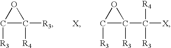

QH, N(R3)H, C(R3)═O, C(R3)(OR3)(OH), C(R3)(OR3)(OR3),
SO2—X, CQOR5, (R3)NCQOR3, N(R3)C=Q, C(R3)(R4)═C(R3)-M,
Diels-Alder diene, C(R3)(R4)═C(R3)(R4), or cyclopentadienyl;
wherein R3 and R4 is are independently H, normal or branched chain alkyl, normal or branched chain alkylene, cycloalkyl, aryl, or aralkyl,
wherein R3 and R4 each independently comprise between 0 and 20 C atoms;
wherein R5 is either H and the second composition further comprises a carbodiimide coupling agent, or pentachlorophenyl, or N-hydroxysuccinimidyl;
wherein Q is O or S;
wherein M is COOH, COOR3, CHO, CN, CON(R3)(R4), NO2, SOR3, or SO2R3,
wherein cyclopentadienyl is any monocyclic or polycyclic cyclopentadienyl radical.;
wherein [Me] designates any metal cation that forms a metallocene complex with cyclopentadiene or derivatives thereof; and
X is F, Cl, Br, or I.
63. The method described in claim 60 wherein the reagent precursor comprises a structure
YSP—RS-TR;
wherein TR is the reagent;
wherein YSP forms a covalent bond with the linker; and
wherein RS comprises (D)n,
wherein each D moiety is independently a heteroatom, a C(R1)(R2) group, an amino acyl residue, a modified amino acyl residue, a nucleotidyl group, or a modified nucleotidyl group;
wherein each R1 and R2 is independently H, OH, normal or branched chain alkyl, normal or branched chain alkylene, cycloalkyl, aryl, normal or branched chain alkoxy, cycloalkoxy, aryloxy, normal or branched chain alkylamino, normal or branched chain alkyleneamino, cycloalkylamino or arylamino; and
wherein R1 and R2 each independently comprise between 0 and 20 C atoms;
64. The method described in claim 63 wherein YSP comprises


QH, N(R3)H, O═C(R3), (R3O)(HO)C(R3)), (R3O)(R3O)C(R3),
X,
X—SO2, R5OCQ, R3OCQN(R3), Q=CNR3, (M)(R3)C═C(R3)(R4),
Diels-Alder diene, C(R3)(R4)═C(R3)(R4), or [Me] +cyclopentadienyl;
wherein R3 and R4 is are independently H, normal or branched chain alkyl, normal or branched chain alkylene, cycloalkyl, aryl, or aralkyl,
wherein each R1 and R2 is independently H, normal or branched chain alkyl, normal or branched chain alkylene, cycloalkyl, aryl, normal or branched chain alkoxy, cycloalkoxy, aryloxy, normal or branched chain alkylamino, normal or branched chain alkyleneamino, cycloalkylamino or arylamino;
wherein R1, R2, R3, and R4 each independently comprise between 0 and 20 C atoms;
wherein R5 is either H and the second composition further comprises a carbodiimide coupling agent, or pentachlorophenyl, or N-hydroxysuccinimidyl;
wherein Q is O or S;
wherein [Me] designates any metal cation that forms a metallocene complex with cyclopentadiene or a derivative thereof;
wherein M is COOH, COOR3, CHO, CN, CON(R3)(R4), NO2, SOR3, or SO2R3;
wherein cyclopentadienyl is any monocyclic or polycyclic cyclopentadienyl radical; and
wherein X is F, Cl, Br, or I.
65. The method described in claim 51 further comprising, in step a), providing a plurality of diffraction grating-based encoded elements; and in step b), binding a reagent to at least a portion of the optical substrate of each diffraction grating-based encoded element provided in step a);
thereby providing a coded reagent library.
66. The method described in claim 65 further comprising
a′) in step a) maintaining a first optical substrate bearing a first code separate from a second substrate bearing a second code, and
b′) in step b) binding a first reagent to the first optical substrate and a second reagent to the second optical substrate.
67. The method described in claim 51 wherein the reagent in step b) is a first nucleotide reagent; and further extending the nucleotide sequence by sequential addition reactions;
thereby providing a coded polynucleotide reagent.
68. The method described in claim 67 further comprising
a) identifying the code embedded in the particle, and
b) identifying the sequence of the polynucleotide,
thereby identifying the coded article as bearing the polynucleotide.
69. The method described in claim 51 wherein the reagent in step b) is a polynucleotide reagent; thereby providing a coded polynucleotide reagent.
70. The method described in claim 51 further comprising, in step a), providing a plurality of diffraction grating-based encoded elements; in step b), binding a first nucleotide reagent to at least a portion of the optical substrate of each diffraction grating-based encoded element provided in step a); and further extending the nucleotide sequence bound to each optical substrate by sequential addition reactions;
thereby providing a coded polynucleotide reagent library.
71. The method described in claim 70 further comprising
a′) in step a) maintaining a first optical substrate bearing a first code separate from a second substrate bearing a second code, and
b′) in step b) and further in the extending step, synthesizing a first polynucleotide on the first optical substrate and a second polynucleotide on the second optical substrate.
72. The method described in claim 51 further comprising, in step a), providing a plurality of diffraction grating-based encoded elements; and in step b), binding a polynucleotide reagent to at least a portion of the optical substrate of each diffraction grating-based encoded element provided in step a);
thereby providing a coded polynucleotide reagent library.
Priority Applications (1)
| Application Number | Priority Date | Filing Date | Title |
|---|---|---|---|
| US11/206,987 US20060057729A1 (en) | 2003-09-12 | 2005-08-18 | Diffraction grating-based encoded element having a substance disposed thereon |
Applications Claiming Priority (9)
| Application Number | Priority Date | Filing Date | Title |
|---|---|---|---|
| US10/661,234 US7106513B2 (en) | 2002-08-20 | 2003-09-12 | Diffraction grating-based encoded particle |
| US10/661,254 US7190522B2 (en) | 2002-09-12 | 2003-09-12 | Chemical synthesis using diffraction grating-based encoded optical elements |
| US10/661,031 US7349158B2 (en) | 2002-09-12 | 2003-09-12 | Diffraction grating-based encoded micro-particles for multiplexed experiments |
| US10/661,082 US7126755B2 (en) | 2002-09-12 | 2003-09-12 | Method and apparatus for labeling using diffraction grating-based encoded optical identification elements |
| US60242704P | 2004-08-18 | 2004-08-18 | |
| US61120504P | 2004-09-17 | 2004-09-17 | |
| US61167604P | 2004-09-20 | 2004-09-20 | |
| US10/990,057 US20050227252A1 (en) | 2002-08-20 | 2004-11-15 | Diffraction grating-based encoded articles for multiplexed experiments |
| US11/206,987 US20060057729A1 (en) | 2003-09-12 | 2005-08-18 | Diffraction grating-based encoded element having a substance disposed thereon |
Related Parent Applications (5)
| Application Number | Title | Priority Date | Filing Date |
|---|---|---|---|
| US10/661,254 Continuation-In-Part US7190522B2 (en) | 2002-08-20 | 2003-09-12 | Chemical synthesis using diffraction grating-based encoded optical elements |
| US10/661,234 Continuation-In-Part US7106513B2 (en) | 2002-08-20 | 2003-09-12 | Diffraction grating-based encoded particle |
| US10/661,082 Continuation-In-Part US7126755B2 (en) | 2002-08-20 | 2003-09-12 | Method and apparatus for labeling using diffraction grating-based encoded optical identification elements |
| US10/661,031 Continuation-In-Part US7349158B2 (en) | 2002-08-20 | 2003-09-12 | Diffraction grating-based encoded micro-particles for multiplexed experiments |
| US10/990,057 Continuation-In-Part US20050227252A1 (en) | 2002-08-20 | 2004-11-15 | Diffraction grating-based encoded articles for multiplexed experiments |
Publications (1)
| Publication Number | Publication Date |
|---|---|
| US20060057729A1 true US20060057729A1 (en) | 2006-03-16 |
Family
ID=36034550
Family Applications (1)
| Application Number | Title | Priority Date | Filing Date |
|---|---|---|---|
| US11/206,987 Abandoned US20060057729A1 (en) | 2003-09-12 | 2005-08-18 | Diffraction grating-based encoded element having a substance disposed thereon |
Country Status (1)
| Country | Link |
|---|---|
| US (1) | US20060057729A1 (en) |
Cited By (25)
| Publication number | Priority date | Publication date | Assignee | Title |
|---|---|---|---|---|
| US20040125424A1 (en) * | 2002-09-12 | 2004-07-01 | Moon John A. | Diffraction grating-based encoded micro-particles for multiplexed experiments |
| US20040130761A1 (en) * | 2002-09-12 | 2004-07-08 | John Moon | Chemical synthesis using diffraction grating-based encoded optical elements |
| US20050220408A1 (en) * | 2004-02-19 | 2005-10-06 | Cyvera Corporation | Optical identification element having non-waveguide photosensitive substrate with diffraction grating therein |
| US20050227252A1 (en) * | 2002-08-20 | 2005-10-13 | Moon John A | Diffraction grating-based encoded articles for multiplexed experiments |
| US20060028727A1 (en) * | 2002-08-20 | 2006-02-09 | Moon John A | Method and apparatus for drug product tracking using encoded optical identification elements |
| US20060063271A1 (en) * | 2002-09-12 | 2006-03-23 | Putnam Martin A | Method and apparatus for aligning microbeads in order to interrogate the same |
| US20060072177A1 (en) * | 2002-08-20 | 2006-04-06 | Putnam Martin A | Diffraction grating-based encoded microparticle assay stick |
| US20060071075A1 (en) * | 2002-08-20 | 2006-04-06 | Moon John A | Optical reader for diffraction grating-based encoded optical identification elements |
| US20060119913A1 (en) * | 2003-08-20 | 2006-06-08 | Illumina, Inc. | Fourier scattering methods for encoding microbeads and methods and apparatus for reading the same |
| US20060118630A1 (en) * | 2004-11-16 | 2006-06-08 | Illumina, Inc. | Holographically encoded elements for microarray and other tagging labeling applications, and method and apparatus for making and reading the same |
| US20060132877A1 (en) * | 2004-11-17 | 2006-06-22 | Illumina, Inc. | Lithographically fabricated holographic optical identification element |
| US20070121181A1 (en) * | 2005-11-22 | 2007-05-31 | Cyvera Corporation | Method and apparatus for labeling using optical identification elements characterized by X-ray diffraction |
| US20070236789A1 (en) * | 2006-04-10 | 2007-10-11 | Moon John A | Optical scanner with improved scan time |
| US20070236796A1 (en) * | 2002-09-12 | 2007-10-11 | Illumina, Inc. | Method of manufacturing of a diffraction grating-based optical identification element |
| US20090194589A1 (en) * | 2002-08-20 | 2009-08-06 | Illumina, Inc. | Optical reader system for substrates having an optically readable code |
| US7659983B2 (en) | 2003-01-22 | 2010-02-09 | Electronics And Telecommunications Resarch Institute | Hybrid random bead/chip based microarray |
| US20100035766A1 (en) * | 2006-05-30 | 2010-02-11 | Fuji Film Corporation | Cell chip |
| US20100246005A1 (en) * | 2002-08-20 | 2010-09-30 | Cyvera Corporation | Encoded particle having a grating with variations in the refractive index |
| US20110059467A1 (en) * | 2007-06-26 | 2011-03-10 | Massachusetts Institute Of Technology | Controlled modification of semiconductor nanocrystals |
| US20110057797A1 (en) * | 2009-09-09 | 2011-03-10 | Absolute Software Corporation | Alert for real-time risk of theft or loss |
| US7923260B2 (en) | 2002-08-20 | 2011-04-12 | Illumina, Inc. | Method of reading encoded particles |
| WO2011053845A2 (en) | 2009-10-30 | 2011-05-05 | Illumina, Inc. | Microvessels, microparticles, and methods of manufacturing and using the same |
| EP2757374A1 (en) * | 2013-01-17 | 2014-07-23 | F. Hoffmann-La Roche AG | Method for preparing an outer surface of a planar waveguide to be capable of binding target samples along a plurality of predetermined lines and a planar waveguide |
| US20170274374A1 (en) * | 2016-03-28 | 2017-09-28 | Ilumina, Inc. | Multi-plane microarrays |
| CN110776917A (en) * | 2019-11-19 | 2020-02-11 | 宁波纳鼎新材料科技有限公司 | Quantum dot and synthetic method thereof |
Citations (94)
| Publication number | Priority date | Publication date | Assignee | Title |
|---|---|---|---|---|
| US3791788A (en) * | 1970-06-30 | 1974-02-12 | Monsanto Co | Method for washing a tow |
| US3858979A (en) * | 1971-09-29 | 1975-01-07 | Colorant Schmuckstein Gmbh | Method of determining the properties of a jewelery stone and apparatus for this method |
| US3880497A (en) * | 1973-03-09 | 1975-04-29 | Xerox Corp | Method of storing optical information on a random carrier |
| US4011435A (en) * | 1974-02-01 | 1977-03-08 | Ncr Corporation | Optical indicia marking and detection system |
| US4445229A (en) * | 1980-03-12 | 1984-04-24 | U.S. Philips Corporation | Device for adjusting a movable electro-acoustic sound transducer |
| US4647544A (en) * | 1984-06-25 | 1987-03-03 | Nicoli David F | Immunoassay using optical interference detection |
| US4725110A (en) * | 1984-08-13 | 1988-02-16 | United Technologies Corporation | Method for impressing gratings within fiber optics |
| US4740468A (en) * | 1985-02-14 | 1988-04-26 | Syntex (U.S.A.) Inc. | Concentrating immunochemical test device and method |
| US4740688A (en) * | 1986-03-20 | 1988-04-26 | Smiths Industries Public Limited Company | Optical transducers with wavelength coding |
| US4816659A (en) * | 1987-10-13 | 1989-03-28 | Control Module Inc. | Bar code reader head |
| US4820006A (en) * | 1977-11-10 | 1989-04-11 | Constant James N | Holographic identification system using incoherent light |
| US4992385A (en) * | 1986-07-24 | 1991-02-12 | Ares-Serono Research And Development Limited Partnership | Polymer-coated optical structures and methods of making and using the same |
| US5003600A (en) * | 1989-08-03 | 1991-03-26 | The United States Of America As Represented By The Department Of Energy | Diffraction gratings used as identifying markers |
| USRE33581E (en) * | 1984-06-25 | 1991-04-30 | Immunoassay using optical interference detection | |
| US5081012A (en) * | 1988-03-29 | 1992-01-14 | Applied Research Systems Ars Holding N.V. | Waveguide sensor with input and reflecting gratings and its use in immunoassay |
| US5089387A (en) * | 1988-07-07 | 1992-02-18 | Adeza Biomedical Corporation | Dna probe diffraction assay and reagents |
| US5090807A (en) * | 1990-01-10 | 1992-02-25 | Environmental Research Institute Of Michigan | Real time optical pre-detection processing of multispectral image data |
| US5095194A (en) * | 1989-10-12 | 1992-03-10 | Joseph Barbanell | Holographic credit card with automatical authentication and verification |
| US5100238A (en) * | 1987-06-11 | 1992-03-31 | Orlon Corporation Limited | Cuvette and apparatus for performing biological assays |
| US5104209A (en) * | 1991-02-19 | 1992-04-14 | Her Majesty The Queen In Right Of Canada, As Represented By The Minister Of Communications | Method of creating an index grating in an optical fiber and a mode converter using the index grating |
| US5192980A (en) * | 1990-06-27 | 1993-03-09 | A. E. Dixon | Apparatus and method for method for spatially- and spectrally-resolved measurements |
| US5196350A (en) * | 1991-05-29 | 1993-03-23 | Omnigene, Inc. | Ligand assay using interference modulation |
| US5200794A (en) * | 1989-08-11 | 1993-04-06 | Nhk Spring Co., Ltd. | Optical head for an optical authenticity identifing system |
| US5283777A (en) * | 1991-04-26 | 1994-02-01 | Pioneer Electronic Corporation | Three-dimensional optical recording medium and optical information recording apparatus using the same |
| US5291027A (en) * | 1992-07-08 | 1994-03-01 | Toppan Printing Co., Ltd. | Optical identification multiple diffraction grating mark member and card using the same |
| US5291006A (en) * | 1989-08-11 | 1994-03-01 | Nhk Spring Co., Ltd. | Authenticity identifying system for information storage cards |
| US5300764A (en) * | 1991-09-11 | 1994-04-05 | Nhk Spring Company, Ltd. | Transparent optical identification label with infrared directivity |
| US5307332A (en) * | 1972-08-25 | 1994-04-26 | Thomson-Csf | Optical disk arrangement with diffractive tracks and a photoelectric assembly providing positional control information |
| US5388173A (en) * | 1993-12-20 | 1995-02-07 | United Technologies Corporation | Method and apparatus for forming aperiodic gratings in optical fibers |
| US5394234A (en) * | 1991-12-19 | 1995-02-28 | Control Module Inc. | Method and apparatus for detecting forged diffraction gratings on identification means |
| US5395558A (en) * | 1991-12-06 | 1995-03-07 | Johnson & Johnson Vision Products, Inc. | Method of making a soft ophthalmic lens |
| US5506674A (en) * | 1992-05-01 | 1996-04-09 | Sumitomo Electric Industries, Ltd. | Method for identifying an optical fiber using a pattern of reflected light |
| US5607188A (en) * | 1994-06-24 | 1997-03-04 | Imation Corp. | Marking of optical disc for customized identification |
| US5610287A (en) * | 1993-12-06 | 1997-03-11 | Molecular Tool, Inc. | Method for immobilizing nucleic acid molecules |
| US5621515A (en) * | 1994-01-25 | 1997-04-15 | Nhk Spring Co., Ltd. | Identification system using regions of predetermined properties interspersed among regions of other properties |
| US5624850A (en) * | 1994-06-06 | 1997-04-29 | Idetek, Inc. | Immunoassays in capillaries |
| US5712912A (en) * | 1995-07-28 | 1998-01-27 | Mytec Technologies Inc. | Method and apparatus for securely handling a personal identification number or cryptographic key using biometric techniques |
| US5721435A (en) * | 1996-04-09 | 1998-02-24 | Hewlett Packard Company | Methods and apparatus for measuring optical properties of biological and chemical substances |
| US5729365A (en) * | 1996-01-11 | 1998-03-17 | Sandia Corporation | Computer generated holographic microtags |
| US5861113A (en) * | 1996-08-01 | 1999-01-19 | The United States Of America As Represented By The Secretary Of Commerce | Fabrication of embossed diffractive optics with reusable release agent |
| US5874187A (en) * | 1996-08-15 | 1999-02-23 | Lucent Technologies Incorporated | Photo recording medium |
| US5881197A (en) * | 1997-02-14 | 1999-03-09 | University Of Southampton | Optical fibre and optical fibre device |
| US6017754A (en) * | 1995-08-24 | 2000-01-25 | Invitrogen Corporation | System for isolating and identifying eukaryotic cells transfected with genes and vectors, host cells and methods thereof |
| US6025283A (en) * | 1995-05-12 | 2000-02-15 | The Real Gold Card Company Limited | Charge card |
| US6025129A (en) * | 1995-04-25 | 2000-02-15 | Irori | Remotely programmable matrices with memories and uses thereof |
| US6027694A (en) * | 1996-10-17 | 2000-02-22 | Texperts, Inc. | Spillproof microplate assembly |
| US6030581A (en) * | 1997-02-28 | 2000-02-29 | Burstein Laboratories | Laboratory in a disk |
| US6035082A (en) * | 1998-03-16 | 2000-03-07 | Luna Innovations, Inc. | Process for preparing an optical fiber sensor with enhanced sensitivity |
| US6036807A (en) * | 1995-12-12 | 2000-03-14 | Ing Groep Nv | Method for applying a security code to an article |
| US6043880A (en) * | 1997-09-15 | 2000-03-28 | Becton Dickinson And Company | Automated optical reader for nucleic acid assays |
| US6174648B1 (en) * | 1997-07-08 | 2001-01-16 | Oki Electric Industry Co., Ltd. | Optical filter fabrication method using fiber holder with spiral groove and phase mask with spiral diffraction grating |
| US6194563B1 (en) * | 1999-03-26 | 2001-02-27 | Vysis, Inc. | Solid phase nucleic acid labeling by transamination |
| US6204969B1 (en) * | 1997-12-08 | 2001-03-20 | Samsung Electronics Co., Ltd. | Amplitude mask, and apparatus and method for manufacturing long period grating filter using the same |
| US6204068B1 (en) * | 1995-03-07 | 2001-03-20 | Erkki Soini | Biospecific assay method |
| US6335824B1 (en) * | 1998-03-20 | 2002-01-01 | Genetic Microsystems, Inc. | Wide field of view and high speed scanning microscopy |
| US20020000471A1 (en) * | 2000-05-03 | 2002-01-03 | Soren Aasmul | Coding of cartridges for an injection device |
| US20020006664A1 (en) * | 1999-09-17 | 2002-01-17 | Sabatini David M. | Arrayed transfection method and uses related thereto |
| US6340588B1 (en) * | 1995-04-25 | 2002-01-22 | Discovery Partners International, Inc. | Matrices with memories |
| US20020022273A1 (en) * | 2000-04-06 | 2002-02-21 | Empedocles Stephen A. | Differentiable spectral bar code methods and systems |
| US20020025534A1 (en) * | 2000-03-22 | 2002-02-28 | Goh M. Cynthia | Method and apparatus for assay for multiple analytes |
| US6352854B1 (en) * | 1995-04-25 | 2002-03-05 | Discovery Partners International, Inc. | Remotely programmable matrices with memories |
| US6356681B1 (en) * | 1999-07-09 | 2002-03-12 | Corning Incorporated | Method and apparatus for trimming the optical path length of optical fiber components |
| US6355198B1 (en) * | 1996-03-15 | 2002-03-12 | President And Fellows Of Harvard College | Method of forming articles including waveguides via capillary micromolding and microtransfer molding |
| US20020034747A1 (en) * | 2000-03-22 | 2002-03-21 | Bruchez Marcel P. | Methods of using semiconductor nanocrystals in bead-based nucleic acid assays |
| US6361958B1 (en) * | 1999-11-12 | 2002-03-26 | Motorola, Inc. | Biochannel assay for hybridization with biomaterial |
| US6363097B1 (en) * | 1998-09-18 | 2002-03-26 | Nec Corporation | Semiconductor laser with a rewritable wavelength stabilizer |
| US20030008323A1 (en) * | 1999-04-15 | 2003-01-09 | Ilya Ravkin | Chemical-library composition and method |
| US6506342B1 (en) * | 1997-06-19 | 2003-01-14 | Robert D. Frankel | Tracking apparatus and method for use with combinatorial synthesis processes |
| US20030021003A1 (en) * | 2001-07-25 | 2003-01-30 | Hiroaki Ono | Beam shutter |
| US6515753B2 (en) * | 2000-05-19 | 2003-02-04 | Aclara Biosciences, Inc. | Optical alignment in capillary detection using capillary wall scatter |
| US20030032203A1 (en) * | 2001-07-10 | 2003-02-13 | Sabatini David M. | Small molecule microarrays |
| US6522406B1 (en) * | 2001-04-20 | 2003-02-18 | Nanometrics Incorporated | Correcting the system polarization sensitivity of a metrology tool having a rotatable polarizer |
| US6524793B1 (en) * | 1995-10-11 | 2003-02-25 | Luminex Corporation | Multiplexed analysis of clinical specimens apparatus and method |
| US6678429B2 (en) * | 2001-08-27 | 2004-01-13 | Lightsmyth Technologies, Inc. | Amplitude and phase control in distributed optical structures |
| US6689316B1 (en) * | 1998-05-29 | 2004-02-10 | Cambridge University Technical Services, Ltd. | Holographic sensors and their production |
| US20040027968A1 (en) * | 2000-10-12 | 2004-02-12 | Hideyoshi Horimai | Optical information recording apparatus and method, optical information reproducing apparatus and method, optical information recording reproducing apparatus and method and optical information recording medium |
| USRE38430E1 (en) * | 1987-03-27 | 2004-02-17 | Becton, Dickinson And Company | Solid phase chromatographic immunoassay |
| US6692912B1 (en) * | 1997-03-05 | 2004-02-17 | Matrix Technologies Corporation | Nucleic acid-containing polymerizable complex |
| US6692031B2 (en) * | 1998-12-31 | 2004-02-17 | Mcgrew Stephen P. | Quantum dot security device and method |
| US20040047030A1 (en) * | 1997-10-29 | 2004-03-11 | Digital Optical Imaging Corporation | Apparatus and methods relating to spatially light modulated microscopy |
| US6708618B1 (en) * | 2000-10-23 | 2004-03-23 | Chialun Tsai | Method and apparatus of using a security feature which includes plural patterned microscopic makers for authentication and to prevent counterfeiting of objects |
| US20050042764A1 (en) * | 2002-02-07 | 2005-02-24 | Sailor Michael J | Optically encoded particles |
| US20050056587A1 (en) * | 2003-09-17 | 2005-03-17 | Vortechnics, Inc. | Apparatus for separating floating and non-floating particulate from a fluid stream |
| US6982996B1 (en) * | 1999-12-06 | 2006-01-03 | Weatherford/Lamb, Inc. | Large diameter optical waveguide, grating, and laser |
| US20060023310A1 (en) * | 2004-02-19 | 2006-02-02 | Putnam Martin A | Optical identification element using separate or partially overlapped diffraction gratings |
| US20060028727A1 (en) * | 2002-08-20 | 2006-02-09 | Moon John A | Method and apparatus for drug product tracking using encoded optical identification elements |
| US20060050544A1 (en) * | 2002-10-09 | 2006-03-09 | Optware Corporation | Information recording method, reproducing method, and recording reproducing method utilizing holography |
| US20060063271A1 (en) * | 2002-09-12 | 2006-03-23 | Putnam Martin A | Method and apparatus for aligning microbeads in order to interrogate the same |
| US20060067179A1 (en) * | 2004-09-16 | 2006-03-30 | Optware Corporation | Optical information recording device and optical information reproduction device |
| US7339148B2 (en) * | 2002-12-16 | 2008-03-04 | Olympus America Inc. | Confocal microscope |
| US20090040885A1 (en) * | 2005-09-09 | 2009-02-12 | Optware Corporation | Search Method |
| US20110003394A1 (en) * | 2002-08-20 | 2011-01-06 | Illumina, Inc. | Encoded microparticles |
| US20110033948A9 (en) * | 2002-08-20 | 2011-02-10 | Cyvera Corporation | Method of reading encoded particles |
| US20110058172A1 (en) * | 2003-01-22 | 2011-03-10 | Illumina, Inc. | Methods of identifying analytes and using encoded particles |
-
2005
- 2005-08-18 US US11/206,987 patent/US20060057729A1/en not_active Abandoned
Patent Citations (98)
| Publication number | Priority date | Publication date | Assignee | Title |
|---|---|---|---|---|
| US3791788A (en) * | 1970-06-30 | 1974-02-12 | Monsanto Co | Method for washing a tow |
| US3858979A (en) * | 1971-09-29 | 1975-01-07 | Colorant Schmuckstein Gmbh | Method of determining the properties of a jewelery stone and apparatus for this method |
| US5307332A (en) * | 1972-08-25 | 1994-04-26 | Thomson-Csf | Optical disk arrangement with diffractive tracks and a photoelectric assembly providing positional control information |
| US3880497A (en) * | 1973-03-09 | 1975-04-29 | Xerox Corp | Method of storing optical information on a random carrier |
| US4011435A (en) * | 1974-02-01 | 1977-03-08 | Ncr Corporation | Optical indicia marking and detection system |
| US4820006A (en) * | 1977-11-10 | 1989-04-11 | Constant James N | Holographic identification system using incoherent light |
| US4445229A (en) * | 1980-03-12 | 1984-04-24 | U.S. Philips Corporation | Device for adjusting a movable electro-acoustic sound transducer |
| US4647544A (en) * | 1984-06-25 | 1987-03-03 | Nicoli David F | Immunoassay using optical interference detection |
| USRE33581E (en) * | 1984-06-25 | 1991-04-30 | Immunoassay using optical interference detection | |
| US4725110A (en) * | 1984-08-13 | 1988-02-16 | United Technologies Corporation | Method for impressing gratings within fiber optics |
| US4807950A (en) * | 1984-08-13 | 1989-02-28 | United Technologies Corporation | Method for impressing gratings within fiber optics |
| US4740468A (en) * | 1985-02-14 | 1988-04-26 | Syntex (U.S.A.) Inc. | Concentrating immunochemical test device and method |
| US4740688A (en) * | 1986-03-20 | 1988-04-26 | Smiths Industries Public Limited Company | Optical transducers with wavelength coding |
| US4992385A (en) * | 1986-07-24 | 1991-02-12 | Ares-Serono Research And Development Limited Partnership | Polymer-coated optical structures and methods of making and using the same |
| USRE38430E1 (en) * | 1987-03-27 | 2004-02-17 | Becton, Dickinson And Company | Solid phase chromatographic immunoassay |
| US5100238A (en) * | 1987-06-11 | 1992-03-31 | Orlon Corporation Limited | Cuvette and apparatus for performing biological assays |
| US4816659A (en) * | 1987-10-13 | 1989-03-28 | Control Module Inc. | Bar code reader head |
| US5081012A (en) * | 1988-03-29 | 1992-01-14 | Applied Research Systems Ars Holding N.V. | Waveguide sensor with input and reflecting gratings and its use in immunoassay |
| US5089387A (en) * | 1988-07-07 | 1992-02-18 | Adeza Biomedical Corporation | Dna probe diffraction assay and reagents |
| US5003600A (en) * | 1989-08-03 | 1991-03-26 | The United States Of America As Represented By The Department Of Energy | Diffraction gratings used as identifying markers |
| US5291006A (en) * | 1989-08-11 | 1994-03-01 | Nhk Spring Co., Ltd. | Authenticity identifying system for information storage cards |
| US5200794A (en) * | 1989-08-11 | 1993-04-06 | Nhk Spring Co., Ltd. | Optical head for an optical authenticity identifing system |
| US5095194A (en) * | 1989-10-12 | 1992-03-10 | Joseph Barbanell | Holographic credit card with automatical authentication and verification |
| US5090807A (en) * | 1990-01-10 | 1992-02-25 | Environmental Research Institute Of Michigan | Real time optical pre-detection processing of multispectral image data |
| US5192980A (en) * | 1990-06-27 | 1993-03-09 | A. E. Dixon | Apparatus and method for method for spatially- and spectrally-resolved measurements |
| US5104209A (en) * | 1991-02-19 | 1992-04-14 | Her Majesty The Queen In Right Of Canada, As Represented By The Minister Of Communications | Method of creating an index grating in an optical fiber and a mode converter using the index grating |
| US5283777A (en) * | 1991-04-26 | 1994-02-01 | Pioneer Electronic Corporation | Three-dimensional optical recording medium and optical information recording apparatus using the same |
| US5196350A (en) * | 1991-05-29 | 1993-03-23 | Omnigene, Inc. | Ligand assay using interference modulation |
| US5300764A (en) * | 1991-09-11 | 1994-04-05 | Nhk Spring Company, Ltd. | Transparent optical identification label with infrared directivity |
| US5395558A (en) * | 1991-12-06 | 1995-03-07 | Johnson & Johnson Vision Products, Inc. | Method of making a soft ophthalmic lens |
| US5394234A (en) * | 1991-12-19 | 1995-02-28 | Control Module Inc. | Method and apparatus for detecting forged diffraction gratings on identification means |
| US5506674A (en) * | 1992-05-01 | 1996-04-09 | Sumitomo Electric Industries, Ltd. | Method for identifying an optical fiber using a pattern of reflected light |
| US5291027A (en) * | 1992-07-08 | 1994-03-01 | Toppan Printing Co., Ltd. | Optical identification multiple diffraction grating mark member and card using the same |
| US5610287A (en) * | 1993-12-06 | 1997-03-11 | Molecular Tool, Inc. | Method for immobilizing nucleic acid molecules |
| US5388173A (en) * | 1993-12-20 | 1995-02-07 | United Technologies Corporation | Method and apparatus for forming aperiodic gratings in optical fibers |
| US5621515A (en) * | 1994-01-25 | 1997-04-15 | Nhk Spring Co., Ltd. | Identification system using regions of predetermined properties interspersed among regions of other properties |
| US5624850A (en) * | 1994-06-06 | 1997-04-29 | Idetek, Inc. | Immunoassays in capillaries |
| US5607188A (en) * | 1994-06-24 | 1997-03-04 | Imation Corp. | Marking of optical disc for customized identification |
| US6204068B1 (en) * | 1995-03-07 | 2001-03-20 | Erkki Soini | Biospecific assay method |
| US6340588B1 (en) * | 1995-04-25 | 2002-01-22 | Discovery Partners International, Inc. | Matrices with memories |
| US6352854B1 (en) * | 1995-04-25 | 2002-03-05 | Discovery Partners International, Inc. | Remotely programmable matrices with memories |
| US6025129A (en) * | 1995-04-25 | 2000-02-15 | Irori | Remotely programmable matrices with memories and uses thereof |
| US6025283A (en) * | 1995-05-12 | 2000-02-15 | The Real Gold Card Company Limited | Charge card |
| US5712912A (en) * | 1995-07-28 | 1998-01-27 | Mytec Technologies Inc. | Method and apparatus for securely handling a personal identification number or cryptographic key using biometric techniques |
| US6017754A (en) * | 1995-08-24 | 2000-01-25 | Invitrogen Corporation | System for isolating and identifying eukaryotic cells transfected with genes and vectors, host cells and methods thereof |
| US6524793B1 (en) * | 1995-10-11 | 2003-02-25 | Luminex Corporation | Multiplexed analysis of clinical specimens apparatus and method |
| US6036807A (en) * | 1995-12-12 | 2000-03-14 | Ing Groep Nv | Method for applying a security code to an article |
| US5729365A (en) * | 1996-01-11 | 1998-03-17 | Sandia Corporation | Computer generated holographic microtags |
| US6355198B1 (en) * | 1996-03-15 | 2002-03-12 | President And Fellows Of Harvard College | Method of forming articles including waveguides via capillary micromolding and microtransfer molding |
| US5721435A (en) * | 1996-04-09 | 1998-02-24 | Hewlett Packard Company | Methods and apparatus for measuring optical properties of biological and chemical substances |
| US5861113A (en) * | 1996-08-01 | 1999-01-19 | The United States Of America As Represented By The Secretary Of Commerce | Fabrication of embossed diffractive optics with reusable release agent |
| US5874187A (en) * | 1996-08-15 | 1999-02-23 | Lucent Technologies Incorporated | Photo recording medium |
| US6027694A (en) * | 1996-10-17 | 2000-02-22 | Texperts, Inc. | Spillproof microplate assembly |
| US5881197A (en) * | 1997-02-14 | 1999-03-09 | University Of Southampton | Optical fibre and optical fibre device |
| US6030581A (en) * | 1997-02-28 | 2000-02-29 | Burstein Laboratories | Laboratory in a disk |
| US6692912B1 (en) * | 1997-03-05 | 2004-02-17 | Matrix Technologies Corporation | Nucleic acid-containing polymerizable complex |
| US6506342B1 (en) * | 1997-06-19 | 2003-01-14 | Robert D. Frankel | Tracking apparatus and method for use with combinatorial synthesis processes |
| US6174648B1 (en) * | 1997-07-08 | 2001-01-16 | Oki Electric Industry Co., Ltd. | Optical filter fabrication method using fiber holder with spiral groove and phase mask with spiral diffraction grating |
| US6043880A (en) * | 1997-09-15 | 2000-03-28 | Becton Dickinson And Company | Automated optical reader for nucleic acid assays |
| US20040047030A1 (en) * | 1997-10-29 | 2004-03-11 | Digital Optical Imaging Corporation | Apparatus and methods relating to spatially light modulated microscopy |
| US6204969B1 (en) * | 1997-12-08 | 2001-03-20 | Samsung Electronics Co., Ltd. | Amplitude mask, and apparatus and method for manufacturing long period grating filter using the same |
| US6035082A (en) * | 1998-03-16 | 2000-03-07 | Luna Innovations, Inc. | Process for preparing an optical fiber sensor with enhanced sensitivity |
| US6335824B1 (en) * | 1998-03-20 | 2002-01-01 | Genetic Microsystems, Inc. | Wide field of view and high speed scanning microscopy |
| US6689316B1 (en) * | 1998-05-29 | 2004-02-10 | Cambridge University Technical Services, Ltd. | Holographic sensors and their production |
| US6363097B1 (en) * | 1998-09-18 | 2002-03-26 | Nec Corporation | Semiconductor laser with a rewritable wavelength stabilizer |
| US6692031B2 (en) * | 1998-12-31 | 2004-02-17 | Mcgrew Stephen P. | Quantum dot security device and method |
| US6194563B1 (en) * | 1999-03-26 | 2001-02-27 | Vysis, Inc. | Solid phase nucleic acid labeling by transamination |
| US20030008323A1 (en) * | 1999-04-15 | 2003-01-09 | Ilya Ravkin | Chemical-library composition and method |
| US6356681B1 (en) * | 1999-07-09 | 2002-03-12 | Corning Incorporated | Method and apparatus for trimming the optical path length of optical fiber components |
| US20020006664A1 (en) * | 1999-09-17 | 2002-01-17 | Sabatini David M. | Arrayed transfection method and uses related thereto |
| US6361958B1 (en) * | 1999-11-12 | 2002-03-26 | Motorola, Inc. | Biochannel assay for hybridization with biomaterial |
| US6982996B1 (en) * | 1999-12-06 | 2006-01-03 | Weatherford/Lamb, Inc. | Large diameter optical waveguide, grating, and laser |
| US20020034747A1 (en) * | 2000-03-22 | 2002-03-21 | Bruchez Marcel P. | Methods of using semiconductor nanocrystals in bead-based nucleic acid assays |
| US20020025534A1 (en) * | 2000-03-22 | 2002-02-28 | Goh M. Cynthia | Method and apparatus for assay for multiple analytes |
| US20020022273A1 (en) * | 2000-04-06 | 2002-02-21 | Empedocles Stephen A. | Differentiable spectral bar code methods and systems |
| US20020000471A1 (en) * | 2000-05-03 | 2002-01-03 | Soren Aasmul | Coding of cartridges for an injection device |
| US6533183B2 (en) * | 2000-05-03 | 2003-03-18 | Novo Nordisk A/S | Coding of cartridges for an injection device |
| US6515753B2 (en) * | 2000-05-19 | 2003-02-04 | Aclara Biosciences, Inc. | Optical alignment in capillary detection using capillary wall scatter |
| US20040027968A1 (en) * | 2000-10-12 | 2004-02-12 | Hideyoshi Horimai | Optical information recording apparatus and method, optical information reproducing apparatus and method, optical information recording reproducing apparatus and method and optical information recording medium |
| US6708618B1 (en) * | 2000-10-23 | 2004-03-23 | Chialun Tsai | Method and apparatus of using a security feature which includes plural patterned microscopic makers for authentication and to prevent counterfeiting of objects |
| US6522406B1 (en) * | 2001-04-20 | 2003-02-18 | Nanometrics Incorporated | Correcting the system polarization sensitivity of a metrology tool having a rotatable polarizer |
| US20030032203A1 (en) * | 2001-07-10 | 2003-02-13 | Sabatini David M. | Small molecule microarrays |
| US20030021003A1 (en) * | 2001-07-25 | 2003-01-30 | Hiroaki Ono | Beam shutter |
| US6678429B2 (en) * | 2001-08-27 | 2004-01-13 | Lightsmyth Technologies, Inc. | Amplitude and phase control in distributed optical structures |
| US20050042764A1 (en) * | 2002-02-07 | 2005-02-24 | Sailor Michael J | Optically encoded particles |
| US20110003394A1 (en) * | 2002-08-20 | 2011-01-06 | Illumina, Inc. | Encoded microparticles |
| US20110033948A9 (en) * | 2002-08-20 | 2011-02-10 | Cyvera Corporation | Method of reading encoded particles |
| US20060028727A1 (en) * | 2002-08-20 | 2006-02-09 | Moon John A | Method and apparatus for drug product tracking using encoded optical identification elements |
| US20060063271A1 (en) * | 2002-09-12 | 2006-03-23 | Putnam Martin A | Method and apparatus for aligning microbeads in order to interrogate the same |
| US20100072278A1 (en) * | 2002-09-12 | 2010-03-25 | Illumina, Inc. | Method and apparatus for aligning microbeads in order to interrogate the same |
| US20060050544A1 (en) * | 2002-10-09 | 2006-03-09 | Optware Corporation | Information recording method, reproducing method, and recording reproducing method utilizing holography |
| US7321541B2 (en) * | 2002-10-09 | 2008-01-22 | Optware Corporation | Information recording method, reproducing method, and recording/reproducing method utilizing holography |
| US7339148B2 (en) * | 2002-12-16 | 2008-03-04 | Olympus America Inc. | Confocal microscope |
| US20110058172A1 (en) * | 2003-01-22 | 2011-03-10 | Illumina, Inc. | Methods of identifying analytes and using encoded particles |
| US20050056587A1 (en) * | 2003-09-17 | 2005-03-17 | Vortechnics, Inc. | Apparatus for separating floating and non-floating particulate from a fluid stream |
| US20060023310A1 (en) * | 2004-02-19 | 2006-02-02 | Putnam Martin A | Optical identification element using separate or partially overlapped diffraction gratings |
| US20060067179A1 (en) * | 2004-09-16 | 2006-03-30 | Optware Corporation | Optical information recording device and optical information reproduction device |
| US20090040885A1 (en) * | 2005-09-09 | 2009-02-12 | Optware Corporation | Search Method |
Non-Patent Citations (1)
| Title |
|---|
| Lawton, C. Biomolecular Self-Assembly of Quantum Dot Composites(1994). Materials Research Society. Vol 330.Pages 283-288. * |
Cited By (63)
| Publication number | Priority date | Publication date | Assignee | Title |
|---|---|---|---|---|
| US20090194589A1 (en) * | 2002-08-20 | 2009-08-06 | Illumina, Inc. | Optical reader system for substrates having an optically readable code |
| US8614852B2 (en) | 2002-08-20 | 2013-12-24 | Illumina, Inc. | Elongated microparticles having an optically detectable code configured to at least one of reflect or filter light |
| US8498052B2 (en) | 2002-08-20 | 2013-07-30 | Illumina, Inc. | Composition including an item and an encoded optical substrate and a method for identifying an item |
| US20050227252A1 (en) * | 2002-08-20 | 2005-10-13 | Moon John A | Diffraction grating-based encoded articles for multiplexed experiments |
| US20060028727A1 (en) * | 2002-08-20 | 2006-02-09 | Moon John A | Method and apparatus for drug product tracking using encoded optical identification elements |
| US8333325B2 (en) | 2002-08-20 | 2012-12-18 | Illumina, Inc. | Optical reader system for substrates having an optically readable code |
| US20060072177A1 (en) * | 2002-08-20 | 2006-04-06 | Putnam Martin A | Diffraction grating-based encoded microparticle assay stick |
| US20060071075A1 (en) * | 2002-08-20 | 2006-04-06 | Moon John A | Optical reader for diffraction grating-based encoded optical identification elements |
| US20110114729A1 (en) * | 2002-08-20 | 2011-05-19 | Illumina, Inc. | Optical reader system for substrates having an optically readable code |
| US7923260B2 (en) | 2002-08-20 | 2011-04-12 | Illumina, Inc. | Method of reading encoded particles |
| US7901630B2 (en) | 2002-08-20 | 2011-03-08 | Illumina, Inc. | Diffraction grating-based encoded microparticle assay stick |
| US7900836B2 (en) | 2002-08-20 | 2011-03-08 | Illumina, Inc. | Optical reader system for substrates having an optically readable code |
| US7872804B2 (en) | 2002-08-20 | 2011-01-18 | Illumina, Inc. | Encoded particle having a grating with variations in the refractive index |
| US20100246007A1 (en) * | 2002-08-20 | 2010-09-30 | Illumina Corporation | composition including an item and an encoded optical substrate and a method for identifying an item |
| US20100246005A1 (en) * | 2002-08-20 | 2010-09-30 | Cyvera Corporation | Encoded particle having a grating with variations in the refractive index |
| US7619819B2 (en) * | 2002-08-20 | 2009-11-17 | Illumina, Inc. | Method and apparatus for drug product tracking using encoded optical identification elements |
| US7898735B2 (en) | 2002-09-12 | 2011-03-01 | Illumina, Inc. | Methods and systems for writing an optical code within or on a fiber substrate |
| US20100255603A9 (en) * | 2002-09-12 | 2010-10-07 | Putnam Martin A | Method and apparatus for aligning microbeads in order to interrogate the same |
| US20080165656A1 (en) * | 2002-09-12 | 2008-07-10 | Moon John A | Method of Manufacturing of a Diffraction Grating-Based Optical Identification Element |
| US7349158B2 (en) * | 2002-09-12 | 2008-03-25 | Cyvera Corporation | Diffraction grating-based encoded micro-particles for multiplexed experiments |
| US20040130761A1 (en) * | 2002-09-12 | 2004-07-08 | John Moon | Chemical synthesis using diffraction grating-based encoded optical elements |
| US8470605B2 (en) | 2002-09-12 | 2013-06-25 | Illumina, Inc. | Optical reader for reading encoded microparticles |
| US20060063271A1 (en) * | 2002-09-12 | 2006-03-23 | Putnam Martin A | Method and apparatus for aligning microbeads in order to interrogate the same |
| US7190522B2 (en) * | 2002-09-12 | 2007-03-13 | Cyvera Corporation | Chemical synthesis using diffraction grating-based encoded optical elements |
| US20040125424A1 (en) * | 2002-09-12 | 2004-07-01 | Moon John A. | Diffraction grating-based encoded micro-particles for multiplexed experiments |
| US20070236796A1 (en) * | 2002-09-12 | 2007-10-11 | Illumina, Inc. | Method of manufacturing of a diffraction grating-based optical identification element |
| US9268983B2 (en) | 2003-01-22 | 2016-02-23 | Illumina, Inc. | Optical system and method for reading encoded microbeads |
| US20110058172A1 (en) * | 2003-01-22 | 2011-03-10 | Illumina, Inc. | Methods of identifying analytes and using encoded particles |
| US7659983B2 (en) | 2003-01-22 | 2010-02-09 | Electronics And Telecommunications Resarch Institute | Hybrid random bead/chip based microarray |
| US7843567B2 (en) | 2003-01-22 | 2010-11-30 | Illumina, Inc. | Methods of identifying an analyte and nucleic acid analysis |
| US20100099574A1 (en) * | 2003-01-22 | 2010-04-22 | Cyvera Corporation | Methods of identifying an analyte and nucleic acid analysis |
| US8049893B2 (en) | 2003-01-22 | 2011-11-01 | Illumina, Inc. | Methods of identifying analytes and using encoded particles |
| US8081792B2 (en) | 2003-08-20 | 2011-12-20 | Illumina, Inc. | Fourier scattering methods for encoding microbeads and methods and apparatus for reading the same |
| US20060119913A1 (en) * | 2003-08-20 | 2006-06-08 | Illumina, Inc. | Fourier scattering methods for encoding microbeads and methods and apparatus for reading the same |
| US8565475B2 (en) | 2003-08-20 | 2013-10-22 | Illumina, Inc. | Optical system and method for reading encoded microbeads |
| US7791802B2 (en) | 2004-02-19 | 2010-09-07 | Illumina, Inc. | Optical identification element having a non-waveguide substrate |
| US20050220408A1 (en) * | 2004-02-19 | 2005-10-06 | Cyvera Corporation | Optical identification element having non-waveguide photosensitive substrate with diffraction grating therein |
| US20060118630A1 (en) * | 2004-11-16 | 2006-06-08 | Illumina, Inc. | Holographically encoded elements for microarray and other tagging labeling applications, and method and apparatus for making and reading the same |
| US20090073520A1 (en) * | 2004-11-17 | 2009-03-19 | Illumina, Inc. | Encoded microparticles and a method for fabricating |
| US20060132877A1 (en) * | 2004-11-17 | 2006-06-22 | Illumina, Inc. | Lithographically fabricated holographic optical identification element |
| US7796333B2 (en) | 2004-11-17 | 2010-09-14 | Illumina, Inc. | Encoded microparticles and a method for fabricating |
| US20070121181A1 (en) * | 2005-11-22 | 2007-05-31 | Cyvera Corporation | Method and apparatus for labeling using optical identification elements characterized by X-ray diffraction |
| US20070236789A1 (en) * | 2006-04-10 | 2007-10-11 | Moon John A | Optical scanner with improved scan time |
| US7830575B2 (en) | 2006-04-10 | 2010-11-09 | Illumina, Inc. | Optical scanner with improved scan time |
| US20100035766A1 (en) * | 2006-05-30 | 2010-02-11 | Fuji Film Corporation | Cell chip |
| US20110059467A1 (en) * | 2007-06-26 | 2011-03-10 | Massachusetts Institute Of Technology | Controlled modification of semiconductor nanocrystals |
| US20110057797A1 (en) * | 2009-09-09 | 2011-03-10 | Absolute Software Corporation | Alert for real-time risk of theft or loss |
| US20110105361A1 (en) * | 2009-10-30 | 2011-05-05 | Illumina, Inc. | Microvessels, microparticles, and methods of manufacturing and using the same |
| US9023638B2 (en) | 2009-10-30 | 2015-05-05 | Illumina, Inc. | Microvessels, microparticles, and methods of manufacturing and using the same |
| WO2011053845A2 (en) | 2009-10-30 | 2011-05-05 | Illumina, Inc. | Microvessels, microparticles, and methods of manufacturing and using the same |
| US8524450B2 (en) | 2009-10-30 | 2013-09-03 | Illumina, Inc. | Microvessels, microparticles, and methods of manufacturing and using the same |
| JP2016505140A (en) * | 2013-01-17 | 2016-02-18 | エフ.ホフマン−ラ ロッシュ アーゲー | Method for preparing outer surface of planar waveguide so that target sample can be coupled along a plurality of predetermined lines, and planar waveguide |
| KR20150105473A (en) * | 2013-01-17 | 2015-09-16 | 에프. 호프만-라 로슈 아게 | Method for preparing an outer surface of a planar waveguide to be capable of binding target samples along a plurality of predetermined lines and a planar waveguide |
| CN104937417A (en) * | 2013-01-17 | 2015-09-23 | 弗·哈夫曼-拉罗切有限公司 | Method for preparing outer surface of planar waveguide to be capable of binding target samples along plurality of predetermined lines and planar waveguide |
| WO2014111521A1 (en) * | 2013-01-17 | 2014-07-24 | F. Hoffmann-La Roche Ag | Method for preparing an outer surface of a planar waveguide to be capable of binding target samples along a plurality of predetermined lines and a planar waveguide |
| EP2757374A1 (en) * | 2013-01-17 | 2014-07-23 | F. Hoffmann-La Roche AG | Method for preparing an outer surface of a planar waveguide to be capable of binding target samples along a plurality of predetermined lines and a planar waveguide |
| US9405069B2 (en) | 2013-01-17 | 2016-08-02 | Hoffmann-La Roche Inc. | Method for preparing an outer surface of a planar waveguide to be capable of binding target samples along a plurality of predeterminded lines and a planar waveguide |
| RU2674696C2 (en) * | 2013-01-17 | 2018-12-12 | Ф. Хоффманн-Ля Рош Аг | Method for preparing outer surface of planar waveguide to be capable of binding target samples along plurality of predetermined lines and planar waveguide |
| KR102216084B1 (en) | 2013-01-17 | 2021-02-17 | 에프. 호프만-라 로슈 아게 | Method for preparing an outer surface of a planar waveguide to be capable of binding target samples along a plurality of predetermined lines and a planar waveguide |
| US20170274374A1 (en) * | 2016-03-28 | 2017-09-28 | Ilumina, Inc. | Multi-plane microarrays |
| EP3831484A1 (en) | 2016-03-28 | 2021-06-09 | Illumina, Inc. | Multi-plane microarrays |
| US20230149933A1 (en) * | 2016-03-28 | 2023-05-18 | Illumina, Inc. | Multi-plane microarrays |
| CN110776917A (en) * | 2019-11-19 | 2020-02-11 | 宁波纳鼎新材料科技有限公司 | Quantum dot and synthetic method thereof |
Similar Documents
| Publication | Publication Date | Title |
|---|---|---|
| US20060057729A1 (en) | Diffraction grating-based encoded element having a substance disposed thereon | |
| US20050227252A1 (en) | Diffraction grating-based encoded articles for multiplexed experiments | |
| US7164533B2 (en) | Hybrid random bead/chip based microarray | |
| US7349158B2 (en) | Diffraction grating-based encoded micro-particles for multiplexed experiments | |
| JP4684507B2 (en) | How to use the sensor platform | |
| AU2003265584C1 (en) | Diffraction grating-based encoded micro-particles for multiplexed experiments | |
| US7923260B2 (en) | Method of reading encoded particles | |
| US7872804B2 (en) | Encoded particle having a grating with variations in the refractive index | |
| EP2538220B1 (en) | Methods and arrays for target analyte detection and determination of target analyte concentration in solution | |
| CA2539187C (en) | Label-free methods for performing assays using a colorimetric resonant reflectance optical biosensor | |
| US7190522B2 (en) | Chemical synthesis using diffraction grating-based encoded optical elements | |
| AU2005337803B2 (en) | Process for determining one or more analytes in samples of biological origin having complex composition, and use thereof | |
| JP2005537487A (en) | Analysis platform and detection method using an analyte measured as an immobilized specific binding partner in a sample after optionally fractionated in the sample | |
| Kisley et al. | Molecular approaches to chromatography using single molecule spectroscopy | |
| US20080020409A1 (en) | Analytical Platform and Method for Generating Protein Expression Profiles of Cell Populations | |
| US20050059014A1 (en) | Analytical platform and detection method with the analytes to be determined in a sample as immobilized specific binding partners | |
| CA2545441A1 (en) | Diffraction grating-based encoded articles for multiplexed experiments | |
| WO2004066210A1 (en) | Hybrid random bead/chip based microarray | |
| ES2339096A1 (en) | Method for the chemical modification of tantalum pentoxide surfaces |
Legal Events
| Date | Code | Title | Description |
|---|---|---|---|
| AS | Assignment |
Owner name: ILLUMINA, INC., CALIFORNIA Free format text: ASSIGNMENT OF ASSIGNORS INTEREST;ASSIGNORS:MOON, JOHN A.;PUTNAM, MARTIN A.;PERBOST, MICHEL;REEL/FRAME:017170/0738;SIGNING DATES FROM 20060207 TO 20060214 |
|
| STCB | Information on status: application discontinuation |
Free format text: ABANDONED -- FAILURE TO RESPOND TO AN OFFICE ACTION |