US20060176428A1 - Optical compensatory sheet having optically anisotropic layer formed from liquid crystal molecules - Google Patents
Optical compensatory sheet having optically anisotropic layer formed from liquid crystal molecules Download PDFInfo
- Publication number
- US20060176428A1 US20060176428A1 US11/395,160 US39516006A US2006176428A1 US 20060176428 A1 US20060176428 A1 US 20060176428A1 US 39516006 A US39516006 A US 39516006A US 2006176428 A1 US2006176428 A1 US 2006176428A1
- Authority
- US
- United States
- Prior art keywords
- liquid crystal
- crystal molecules
- optical compensatory
- compensatory sheet
- optically anisotropic
- Prior art date
- Legal status (The legal status is an assumption and is not a legal conclusion. Google has not performed a legal analysis and makes no representation as to the accuracy of the status listed.)
- Granted
Links
- 0 [31*]CC1=NC(C[32*])=NC(C[33*])=N1 Chemical compound [31*]CC1=NC(C[32*])=NC(C[33*])=N1 0.000 description 22
- PIWBOHZHEVOXCA-UHFFFAOYSA-N C#CC.C/C=[C-]/CCC.C=C(C)C.C=CC.CC(=O)O.CC1CN1.CC1CO1.CC=C(C)C.CC=CC.CC=CCC.CC=O.CN.CN=C=O.CN=C=S.CO.CS.CS(=O)(=O)O Chemical compound C#CC.C/C=[C-]/CCC.C=C(C)C.C=CC.CC(=O)O.CC1CN1.CC1CO1.CC=C(C)C.CC=CC.CC=CCC.CC=O.CN.CN=C=O.CN=C=S.CO.CS.CS(=O)(=O)O PIWBOHZHEVOXCA-UHFFFAOYSA-N 0.000 description 1
- KBTGWAWDJHZASP-UHFFFAOYSA-N C=CC(=O)OCCCCOc1ccc(C(=O)OC(C)CC)cc1.CCC(C)O.CCC(C)OC(C)=O Chemical compound C=CC(=O)OCCCCOc1ccc(C(=O)OC(C)CC)cc1.CCC(C)O.CCC(C)OC(C)=O KBTGWAWDJHZASP-UHFFFAOYSA-N 0.000 description 1
- MWRYJJWEBNXMFB-QVGYYPOASA-N CC1=C(C)/C2=C/C3=N4/C(=C\C5=C(C)C(C)=C6/C=C7/C(C)=C(C)C8=N7[Cu]4(N65)N2C1=C8)C(C)=C3C.CC1=CC2=C(C=C1C)C1=C3OC4=C(C=C(C)C(C)=C4)C3=C3OC4=C(C=C(C)C(C)=C4)C3=C1O2.CC1=CC2=C3C(=C1C)C1=CC(C)=C(C)C=C1/C1=C/C(C)=C(/C)C(=C31)C1=CC(C)=C(C)C=C12.CC1=CC=C(C2CC(C3=CC(C)=C(C)C=C3)O[Cu]3(O2)OC(C2=CC=C(C)C(C)=C2)CC(C2=CC(C)=C(C)C=C2)O3)C=C1C.CC1C(C)C(C)C(C)C(C)C1C Chemical compound CC1=C(C)/C2=C/C3=N4/C(=C\C5=C(C)C(C)=C6/C=C7/C(C)=C(C)C8=N7[Cu]4(N65)N2C1=C8)C(C)=C3C.CC1=CC2=C(C=C1C)C1=C3OC4=C(C=C(C)C(C)=C4)C3=C3OC4=C(C=C(C)C(C)=C4)C3=C1O2.CC1=CC2=C3C(=C1C)C1=CC(C)=C(C)C=C1/C1=C/C(C)=C(/C)C(=C31)C1=CC(C)=C(C)C=C12.CC1=CC=C(C2CC(C3=CC(C)=C(C)C=C3)O[Cu]3(O2)OC(C2=CC=C(C)C(C)=C2)CC(C2=CC(C)=C(C)C=C2)O3)C=C1C.CC1C(C)C(C)C(C)C(C)C1C MWRYJJWEBNXMFB-QVGYYPOASA-N 0.000 description 1
- ZQOWTGGCNRIQBI-WHZAZESFSA-N CC1=C2/C=C3\N=C(/C=C4\N/C(=C\C5=N/C(=C\C(=C1C)N2)C(C)=C5C)C(C)=C4C)C(C)=C3C.CC1=CC2=C(C=C1C)C1=C(C=C(C)C(C)=C1)C1=C2C=C(C)C(C)=C1.CC1=CC2=C(C=C1C)C1=C3CC4=C(C=C(C)C(C)=C4)C3=C3CC4=C(C=C(C)C(C)=C4)C3=C1C2.CC1=CC2=C(C=C1C)C1=C3SC4=C(C=C(C)C(C)=C4)C3=C3SC4=C(C=C(C)C(C)=C4)C3=C1S2.CN1CCN(C)CCN(C)CCN(C)CCN(C)CCN(C)CC1 Chemical compound CC1=C2/C=C3\N=C(/C=C4\N/C(=C\C5=N/C(=C\C(=C1C)N2)C(C)=C5C)C(C)=C4C)C(C)=C3C.CC1=CC2=C(C=C1C)C1=C(C=C(C)C(C)=C1)C1=C2C=C(C)C(C)=C1.CC1=CC2=C(C=C1C)C1=C3CC4=C(C=C(C)C(C)=C4)C3=C3CC4=C(C=C(C)C(C)=C4)C3=C1C2.CC1=CC2=C(C=C1C)C1=C3SC4=C(C=C(C)C(C)=C4)C3=C3SC4=C(C=C(C)C(C)=C4)C3=C1S2.CN1CCN(C)CCN(C)CCN(C)CCN(C)CCN(C)CC1 ZQOWTGGCNRIQBI-WHZAZESFSA-N 0.000 description 1
- XJFSKCRUPZFDKV-UHFFFAOYSA-N CC1=CC(C)=NN1C.CC1=CN(C)=CN1C.CC1=CN(C)C(C2=CC=CC=C2)=N1.CC1=CN(C)C(C2=CC=CC=C2)=N1.CC1C(=O)N(C)C(=O)N1C.CCCC[O-]C1C(=O)N(C)C(=O)N1C.CNC(=O)C1=NC=CN1C.COC(=O)C1=CC=CN1C Chemical compound CC1=CC(C)=NN1C.CC1=CN(C)=CN1C.CC1=CN(C)C(C2=CC=CC=C2)=N1.CC1=CN(C)C(C2=CC=CC=C2)=N1.CC1C(=O)N(C)C(=O)N1C.CCCC[O-]C1C(=O)N(C)C(=O)N1C.CNC(=O)C1=NC=CN1C.COC(=O)C1=CC=CN1C XJFSKCRUPZFDKV-UHFFFAOYSA-N 0.000 description 1
- OCCUNCUKRROKMA-RDQJEHLLSA-N CC1=CC2=C(C=C1C)/C1=C/C3C4=C(C=C(C)C(C)=C4)/C4=C/C5=C6C=C(C)C(C)=CC6=C6/C=C7/C8=C(C=C(C)C(C)=C8)C8=N7[Cu](N65)(N1C2=C8)[N@@]43.CC1=CC2=C(C=C1C)C1=C3NC4=C(C=C(C)C(C)=C4)C3=C3NC4=C(C=C(C)C(C)=C4)C3=C1N2 Chemical compound CC1=CC2=C(C=C1C)/C1=C/C3C4=C(C=C(C)C(C)=C4)/C4=C/C5=C6C=C(C)C(C)=CC6=C6/C=C7/C8=C(C=C(C)C(C)=C8)C8=N7[Cu](N65)(N1C2=C8)[N@@]43.CC1=CC2=C(C=C1C)C1=C3NC4=C(C=C(C)C(C)=C4)C3=C3NC4=C(C=C(C)C(C)=C4)C3=C1N2 OCCUNCUKRROKMA-RDQJEHLLSA-N 0.000 description 1
- XLPYBEHTMHTYFY-XBSXSOIGSA-N CC1=CC2=C3/C=C4\N=C(/C=C5\N/C(=C\C6=N/C(=C\C(=C2C=C1C)N3)C1=C6C=C(C)C(C)=C1)C1=C5C=C(C)C(C)=C1)C1=C4C=C(C)C(C)=C1.CC1=CC2=CC(=C1)C#CC1=CC(=CC(C)=C1)C#CC1=CC(=CC(C)=C1)C#CC1=CC(=CC(C)=C1)C#CC1=CC(=CC(C)=C1)C#CC1=CC(=CC(C)=C1)C#C2.CC1=CC=C(C#CC2=C(C#CC3=CC=C(C)C=C3)C(C#CC3=CC=C(C)C=C3)=C(C#CC3=CC=C(C)C=C3)C(C#CC3=CC=C(C)C=C3)=C2C#CC2=CC=C(C)C=C2)C=C1 Chemical compound CC1=CC2=C3/C=C4\N=C(/C=C5\N/C(=C\C6=N/C(=C\C(=C2C=C1C)N3)C1=C6C=C(C)C(C)=C1)C1=C5C=C(C)C(C)=C1)C1=C4C=C(C)C(C)=C1.CC1=CC2=CC(=C1)C#CC1=CC(=CC(C)=C1)C#CC1=CC(=CC(C)=C1)C#CC1=CC(=CC(C)=C1)C#CC1=CC(=CC(C)=C1)C#CC1=CC(=CC(C)=C1)C#C2.CC1=CC=C(C#CC2=C(C#CC3=CC=C(C)C=C3)C(C#CC3=CC=C(C)C=C3)=C(C#CC3=CC=C(C)C=C3)C(C#CC3=CC=C(C)C=C3)=C2C#CC2=CC=C(C)C=C2)C=C1 XLPYBEHTMHTYFY-XBSXSOIGSA-N 0.000 description 1
- SKOJQWRDCRFFLH-UHFFFAOYSA-N CC1=NC=CN1C.CC1=NN(C)C=C1Br.CN1CCOCC1.COC(=O)C1=CN=CN1C Chemical compound CC1=NC=CN1C.CC1=NN(C)C=C1Br.CN1CCOCC1.COC(=O)C1=CN=CN1C SKOJQWRDCRFFLH-UHFFFAOYSA-N 0.000 description 1
- GNXBDHPKVKQVDF-UHFFFAOYSA-M CCC(C)c1ccccc1.CCCCCCCOC(=O)C(C)C(C)C(=O)O.[H]C(F)(F)C(F)(F)C(F)(F)C(F)(F)C(F)(F)C(F)FCOC(=O)CC(C(=O)OCFC(F)C(F)(F)C(F)(F)C(F)(F)C(F)(F)C([H])(F)F)S(=O)(=O)O[Na].[H]COC(C)(C=CC(C)(CC(C)C)OCC(=O)F1[H]C(F)(F)C(F)(F)C(F)(F)C(F)(F)C(F)(F)C(F)(F)C(F)(F)C1F)CC(C)C.[H]FC(F)C(F)(F)C(F)(F)C(F)(F)C(F)(F)C(F)(F)C(F)(F)C(F)(F)C(=O)COC(C)(C#CC(C)(CC(C)C)OCC(=O)F1[H]C(F)(F)C(F)(F)C(F)(F)C(F)(F)C(F)(F)C(F)(F)C(F)(F)C1F)CC(C)C Chemical compound CCC(C)c1ccccc1.CCCCCCCOC(=O)C(C)C(C)C(=O)O.[H]C(F)(F)C(F)(F)C(F)(F)C(F)(F)C(F)(F)C(F)FCOC(=O)CC(C(=O)OCFC(F)C(F)(F)C(F)(F)C(F)(F)C(F)(F)C([H])(F)F)S(=O)(=O)O[Na].[H]COC(C)(C=CC(C)(CC(C)C)OCC(=O)F1[H]C(F)(F)C(F)(F)C(F)(F)C(F)(F)C(F)(F)C(F)(F)C(F)(F)C1F)CC(C)C.[H]FC(F)C(F)(F)C(F)(F)C(F)(F)C(F)(F)C(F)(F)C(F)(F)C(F)(F)C(=O)COC(C)(C#CC(C)(CC(C)C)OCC(=O)F1[H]C(F)(F)C(F)(F)C(F)(F)C(F)(F)C(F)(F)C(F)(F)C(F)(F)C1F)CC(C)C GNXBDHPKVKQVDF-UHFFFAOYSA-M 0.000 description 1
- UGESUEUYNJUERQ-UHFFFAOYSA-N CCCCCCCCCCCCOC1C(=O)N(C2=NC(N3C(=O)C(OCCCCCCCCCCCC)N(CCCCCCCC)C3=O)=NC(N3C(=O)C(OCCCCCCCCCCCC)N(CCCCCCCC)C3=O)=N2)C(=O)N1CCCCCCCC Chemical compound CCCCCCCCCCCCOC1C(=O)N(C2=NC(N3C(=O)C(OCCCCCCCCCCCC)N(CCCCCCCC)C3=O)=NC(N3C(=O)C(OCCCCCCCCCCCC)N(CCCCCCCC)C3=O)=N2)C(=O)N1CCCCCCCC UGESUEUYNJUERQ-UHFFFAOYSA-N 0.000 description 1
- RPNBRDPRIUMQTB-UHFFFAOYSA-N CN1C2=C(C=CC=C2)[N+](C)=C1[Rf] Chemical compound CN1C2=C(C=CC=C2)[N+](C)=C1[Rf] RPNBRDPRIUMQTB-UHFFFAOYSA-N 0.000 description 1
- SJRJJKPEHAURKC-UHFFFAOYSA-N CN1CCOCC1 Chemical compound CN1CCOCC1 SJRJJKPEHAURKC-UHFFFAOYSA-N 0.000 description 1
- UESOBPUTZLYSGI-UHFFFAOYSA-N Cc1n[n](C)cc1Br Chemical compound Cc1n[n](C)cc1Br UESOBPUTZLYSGI-UHFFFAOYSA-N 0.000 description 1
- SXJSETSRWNDWPP-UHFFFAOYSA-N O=C(c1ccccc1)c1ccc(OCc2ccccc2)cc1O Chemical compound O=C(c1ccccc1)c1ccc(OCc2ccccc2)cc1O SXJSETSRWNDWPP-UHFFFAOYSA-N 0.000 description 1
Images


Classifications
-
- C—CHEMISTRY; METALLURGY
- C09—DYES; PAINTS; POLISHES; NATURAL RESINS; ADHESIVES; COMPOSITIONS NOT OTHERWISE PROVIDED FOR; APPLICATIONS OF MATERIALS NOT OTHERWISE PROVIDED FOR
- C09K—MATERIALS FOR MISCELLANEOUS APPLICATIONS, NOT PROVIDED FOR ELSEWHERE
- C09K19/00—Liquid crystal materials
- C09K19/04—Liquid crystal materials characterised by the chemical structure of the liquid crystal components, e.g. by a specific unit
- C09K19/06—Non-steroidal liquid crystal compounds
- C09K19/08—Non-steroidal liquid crystal compounds containing at least two non-condensed rings
- C09K19/30—Non-steroidal liquid crystal compounds containing at least two non-condensed rings containing saturated or unsaturated non-aromatic rings, e.g. cyclohexane rings
- C09K19/3001—Cyclohexane rings
-
- G—PHYSICS
- G02—OPTICS
- G02B—OPTICAL ELEMENTS, SYSTEMS OR APPARATUS
- G02B5/00—Optical elements other than lenses
- G02B5/30—Polarising elements
-
- C—CHEMISTRY; METALLURGY
- C09—DYES; PAINTS; POLISHES; NATURAL RESINS; ADHESIVES; COMPOSITIONS NOT OTHERWISE PROVIDED FOR; APPLICATIONS OF MATERIALS NOT OTHERWISE PROVIDED FOR
- C09K—MATERIALS FOR MISCELLANEOUS APPLICATIONS, NOT PROVIDED FOR ELSEWHERE
- C09K19/00—Liquid crystal materials
- C09K19/04—Liquid crystal materials characterised by the chemical structure of the liquid crystal components, e.g. by a specific unit
- C09K19/06—Non-steroidal liquid crystal compounds
- C09K19/32—Non-steroidal liquid crystal compounds containing condensed ring systems, i.e. fused, bridged or spiro ring systems
-
- C—CHEMISTRY; METALLURGY
- C09—DYES; PAINTS; POLISHES; NATURAL RESINS; ADHESIVES; COMPOSITIONS NOT OTHERWISE PROVIDED FOR; APPLICATIONS OF MATERIALS NOT OTHERWISE PROVIDED FOR
- C09K—MATERIALS FOR MISCELLANEOUS APPLICATIONS, NOT PROVIDED FOR ELSEWHERE
- C09K19/00—Liquid crystal materials
- C09K19/04—Liquid crystal materials characterised by the chemical structure of the liquid crystal components, e.g. by a specific unit
- C09K19/06—Non-steroidal liquid crystal compounds
- C09K19/34—Non-steroidal liquid crystal compounds containing at least one heterocyclic ring
- C09K19/3441—Non-steroidal liquid crystal compounds containing at least one heterocyclic ring having nitrogen as hetero atom
- C09K19/3477—Non-steroidal liquid crystal compounds containing at least one heterocyclic ring having nitrogen as hetero atom the heterocyclic ring being a five-membered aromatic ring containing at least one nitrogen atom
-
- C—CHEMISTRY; METALLURGY
- C09—DYES; PAINTS; POLISHES; NATURAL RESINS; ADHESIVES; COMPOSITIONS NOT OTHERWISE PROVIDED FOR; APPLICATIONS OF MATERIALS NOT OTHERWISE PROVIDED FOR
- C09K—MATERIALS FOR MISCELLANEOUS APPLICATIONS, NOT PROVIDED FOR ELSEWHERE
- C09K19/00—Liquid crystal materials
- C09K19/04—Liquid crystal materials characterised by the chemical structure of the liquid crystal components, e.g. by a specific unit
- C09K19/06—Non-steroidal liquid crystal compounds
- C09K19/34—Non-steroidal liquid crystal compounds containing at least one heterocyclic ring
- C09K19/3441—Non-steroidal liquid crystal compounds containing at least one heterocyclic ring having nitrogen as hetero atom
- C09K19/3488—Non-steroidal liquid crystal compounds containing at least one heterocyclic ring having nitrogen as hetero atom the heterocyclic ring having more than 6 members, e.g. macrocycles, phthalocyanines
-
- C—CHEMISTRY; METALLURGY
- C09—DYES; PAINTS; POLISHES; NATURAL RESINS; ADHESIVES; COMPOSITIONS NOT OTHERWISE PROVIDED FOR; APPLICATIONS OF MATERIALS NOT OTHERWISE PROVIDED FOR
- C09K—MATERIALS FOR MISCELLANEOUS APPLICATIONS, NOT PROVIDED FOR ELSEWHERE
- C09K19/00—Liquid crystal materials
- C09K19/04—Liquid crystal materials characterised by the chemical structure of the liquid crystal components, e.g. by a specific unit
- C09K19/06—Non-steroidal liquid crystal compounds
- C09K19/34—Non-steroidal liquid crystal compounds containing at least one heterocyclic ring
- C09K19/3491—Non-steroidal liquid crystal compounds containing at least one heterocyclic ring having sulfur as hetero atom
-
- C—CHEMISTRY; METALLURGY
- C09—DYES; PAINTS; POLISHES; NATURAL RESINS; ADHESIVES; COMPOSITIONS NOT OTHERWISE PROVIDED FOR; APPLICATIONS OF MATERIALS NOT OTHERWISE PROVIDED FOR
- C09K—MATERIALS FOR MISCELLANEOUS APPLICATIONS, NOT PROVIDED FOR ELSEWHERE
- C09K19/00—Liquid crystal materials
- C09K19/04—Liquid crystal materials characterised by the chemical structure of the liquid crystal components, e.g. by a specific unit
- C09K19/40—Liquid crystal materials characterised by the chemical structure of the liquid crystal components, e.g. by a specific unit containing elements other than carbon, hydrogen, halogen, oxygen, nitrogen or sulfur, e.g. silicon, metals
-
- G—PHYSICS
- G02—OPTICS
- G02B—OPTICAL ELEMENTS, SYSTEMS OR APPARATUS
- G02B5/00—Optical elements other than lenses
- G02B5/30—Polarising elements
- G02B5/3016—Polarising elements involving passive liquid crystal elements
-
- G—PHYSICS
- G02—OPTICS
- G02B—OPTICAL ELEMENTS, SYSTEMS OR APPARATUS
- G02B5/00—Optical elements other than lenses
- G02B5/30—Polarising elements
- G02B5/3025—Polarisers, i.e. arrangements capable of producing a definite output polarisation state from an unpolarised input state
- G02B5/3033—Polarisers, i.e. arrangements capable of producing a definite output polarisation state from an unpolarised input state in the form of a thin sheet or foil, e.g. Polaroid
-
- G—PHYSICS
- G02—OPTICS
- G02F—OPTICAL DEVICES OR ARRANGEMENTS FOR THE CONTROL OF LIGHT BY MODIFICATION OF THE OPTICAL PROPERTIES OF THE MEDIA OF THE ELEMENTS INVOLVED THEREIN; NON-LINEAR OPTICS; FREQUENCY-CHANGING OF LIGHT; OPTICAL LOGIC ELEMENTS; OPTICAL ANALOGUE/DIGITAL CONVERTERS
- G02F1/00—Devices or arrangements for the control of the intensity, colour, phase, polarisation or direction of light arriving from an independent light source, e.g. switching, gating or modulating; Non-linear optics
- G02F1/01—Devices or arrangements for the control of the intensity, colour, phase, polarisation or direction of light arriving from an independent light source, e.g. switching, gating or modulating; Non-linear optics for the control of the intensity, phase, polarisation or colour
- G02F1/13—Devices or arrangements for the control of the intensity, colour, phase, polarisation or direction of light arriving from an independent light source, e.g. switching, gating or modulating; Non-linear optics for the control of the intensity, phase, polarisation or colour based on liquid crystals, e.g. single liquid crystal display cells
- G02F1/133—Constructional arrangements; Operation of liquid crystal cells; Circuit arrangements
- G02F1/1333—Constructional arrangements; Manufacturing methods
- G02F1/1335—Structural association of cells with optical devices, e.g. polarisers or reflectors
- G02F1/13363—Birefringent elements, e.g. for optical compensation
- G02F1/133632—Birefringent elements, e.g. for optical compensation with refractive index ellipsoid inclined relative to the LC-layer surface
-
- G—PHYSICS
- G02—OPTICS
- G02F—OPTICAL DEVICES OR ARRANGEMENTS FOR THE CONTROL OF LIGHT BY MODIFICATION OF THE OPTICAL PROPERTIES OF THE MEDIA OF THE ELEMENTS INVOLVED THEREIN; NON-LINEAR OPTICS; FREQUENCY-CHANGING OF LIGHT; OPTICAL LOGIC ELEMENTS; OPTICAL ANALOGUE/DIGITAL CONVERTERS
- G02F1/00—Devices or arrangements for the control of the intensity, colour, phase, polarisation or direction of light arriving from an independent light source, e.g. switching, gating or modulating; Non-linear optics
- G02F1/01—Devices or arrangements for the control of the intensity, colour, phase, polarisation or direction of light arriving from an independent light source, e.g. switching, gating or modulating; Non-linear optics for the control of the intensity, phase, polarisation or colour
- G02F1/13—Devices or arrangements for the control of the intensity, colour, phase, polarisation or direction of light arriving from an independent light source, e.g. switching, gating or modulating; Non-linear optics for the control of the intensity, phase, polarisation or colour based on liquid crystals, e.g. single liquid crystal display cells
- G02F1/133—Constructional arrangements; Operation of liquid crystal cells; Circuit arrangements
- G02F1/1333—Constructional arrangements; Manufacturing methods
- G02F1/1335—Structural association of cells with optical devices, e.g. polarisers or reflectors
- G02F1/13363—Birefringent elements, e.g. for optical compensation
- G02F1/133634—Birefringent elements, e.g. for optical compensation the refractive index Nz perpendicular to the element surface being different from in-plane refractive indices Nx and Ny, e.g. biaxial or with normal optical axis
-
- C—CHEMISTRY; METALLURGY
- C09—DYES; PAINTS; POLISHES; NATURAL RESINS; ADHESIVES; COMPOSITIONS NOT OTHERWISE PROVIDED FOR; APPLICATIONS OF MATERIALS NOT OTHERWISE PROVIDED FOR
- C09K—MATERIALS FOR MISCELLANEOUS APPLICATIONS, NOT PROVIDED FOR ELSEWHERE
- C09K19/00—Liquid crystal materials
- C09K19/04—Liquid crystal materials characterised by the chemical structure of the liquid crystal components, e.g. by a specific unit
- C09K19/06—Non-steroidal liquid crystal compounds
- C09K19/34—Non-steroidal liquid crystal compounds containing at least one heterocyclic ring
- C09K19/3402—Non-steroidal liquid crystal compounds containing at least one heterocyclic ring having oxygen as hetero atom
- C09K19/3405—Non-steroidal liquid crystal compounds containing at least one heterocyclic ring having oxygen as hetero atom the heterocyclic ring being a five-membered ring
- C09K2019/3408—Five-membered ring with oxygen(s) in fused, bridged or spiro ring systems
-
- C—CHEMISTRY; METALLURGY
- C09—DYES; PAINTS; POLISHES; NATURAL RESINS; ADHESIVES; COMPOSITIONS NOT OTHERWISE PROVIDED FOR; APPLICATIONS OF MATERIALS NOT OTHERWISE PROVIDED FOR
- C09K—MATERIALS FOR MISCELLANEOUS APPLICATIONS, NOT PROVIDED FOR ELSEWHERE
- C09K2323/00—Functional layers of liquid crystal optical display excluding electroactive liquid crystal layer characterised by chemical composition
- C09K2323/02—Alignment layer characterised by chemical composition
-
- G—PHYSICS
- G02—OPTICS
- G02F—OPTICAL DEVICES OR ARRANGEMENTS FOR THE CONTROL OF LIGHT BY MODIFICATION OF THE OPTICAL PROPERTIES OF THE MEDIA OF THE ELEMENTS INVOLVED THEREIN; NON-LINEAR OPTICS; FREQUENCY-CHANGING OF LIGHT; OPTICAL LOGIC ELEMENTS; OPTICAL ANALOGUE/DIGITAL CONVERTERS
- G02F1/00—Devices or arrangements for the control of the intensity, colour, phase, polarisation or direction of light arriving from an independent light source, e.g. switching, gating or modulating; Non-linear optics
- G02F1/01—Devices or arrangements for the control of the intensity, colour, phase, polarisation or direction of light arriving from an independent light source, e.g. switching, gating or modulating; Non-linear optics for the control of the intensity, phase, polarisation or colour
- G02F1/13—Devices or arrangements for the control of the intensity, colour, phase, polarisation or direction of light arriving from an independent light source, e.g. switching, gating or modulating; Non-linear optics for the control of the intensity, phase, polarisation or colour based on liquid crystals, e.g. single liquid crystal display cells
- G02F1/137—Devices or arrangements for the control of the intensity, colour, phase, polarisation or direction of light arriving from an independent light source, e.g. switching, gating or modulating; Non-linear optics for the control of the intensity, phase, polarisation or colour based on liquid crystals, e.g. single liquid crystal display cells characterised by the electro-optical or magneto-optical effect, e.g. field-induced phase transition, orientation effect, guest-host interaction or dynamic scattering
- G02F1/139—Devices or arrangements for the control of the intensity, colour, phase, polarisation or direction of light arriving from an independent light source, e.g. switching, gating or modulating; Non-linear optics for the control of the intensity, phase, polarisation or colour based on liquid crystals, e.g. single liquid crystal display cells characterised by the electro-optical or magneto-optical effect, e.g. field-induced phase transition, orientation effect, guest-host interaction or dynamic scattering based on orientation effects in which the liquid crystal remains transparent
- G02F1/1393—Devices or arrangements for the control of the intensity, colour, phase, polarisation or direction of light arriving from an independent light source, e.g. switching, gating or modulating; Non-linear optics for the control of the intensity, phase, polarisation or colour based on liquid crystals, e.g. single liquid crystal display cells characterised by the electro-optical or magneto-optical effect, e.g. field-induced phase transition, orientation effect, guest-host interaction or dynamic scattering based on orientation effects in which the liquid crystal remains transparent the birefringence of the liquid crystal being electrically controlled, e.g. ECB-, DAP-, HAN-, PI-LC cells
-
- G—PHYSICS
- G02—OPTICS
- G02F—OPTICAL DEVICES OR ARRANGEMENTS FOR THE CONTROL OF LIGHT BY MODIFICATION OF THE OPTICAL PROPERTIES OF THE MEDIA OF THE ELEMENTS INVOLVED THEREIN; NON-LINEAR OPTICS; FREQUENCY-CHANGING OF LIGHT; OPTICAL LOGIC ELEMENTS; OPTICAL ANALOGUE/DIGITAL CONVERTERS
- G02F2413/00—Indexing scheme related to G02F1/13363, i.e. to birefringent elements, e.g. for optical compensation, characterised by the number, position, orientation or value of the compensation plates
- G02F2413/10—Indexing scheme related to G02F1/13363, i.e. to birefringent elements, e.g. for optical compensation, characterised by the number, position, orientation or value of the compensation plates with refractive index ellipsoid inclined, or tilted, relative to the LC-layer surface O plate
- G02F2413/105—Indexing scheme related to G02F1/13363, i.e. to birefringent elements, e.g. for optical compensation, characterised by the number, position, orientation or value of the compensation plates with refractive index ellipsoid inclined, or tilted, relative to the LC-layer surface O plate with varying inclination in thickness direction, e.g. hybrid oriented discotic LC
Definitions
- the present invention relates to an optical compensatory sheet having an optically anisotropic layer formed from liquid crystal molecules.
- the invention also relates to an elliptically polarizing plate and a liquid crystal display equipped with that optical compensatory sheet.
- a liquid crystal display generally has a liquid crystal cell, a polarizing element and an optical compensatory sheet (phase retarder).
- a display of transmission type two polarizing elements are placed on both sides of the liquid crystal cell, and one or two optical compensatory sheets are placed between the liquid crystal cell and the polarizing element.
- a display of reflection type comprises a reflection plate, a liquid crystal cell, one optical compensatory sheet and one polarizing element piled up in this order.
- the liquid crystal cell comprises a pair of substrates, rod-like liquid crystal molecules and an electrode layer.
- the rod-like liquid crystal molecules are provided between the substrates, and the electrode layer has a function of applying a voltage to the rod-like liquid crystal molecules.
- variouis display modes are proposed.
- Examples of the display modes for transmission type include TN (twisted nematic) mode, IPS (in-plane switching) mode, FLC (ferroelectric liquid crystal) mode, OCB (optically compensatory bend) mode, STN (super twisted nematic) mode, VA (vertically aligned) mode and ECB (electrically controlled birefringence) mode.
- Examples of the modes for reflection type include TN mode, HAN (hybrid aligned nematic) mode and GH (guest-host) mode.
- the optical compensatory sheet is widely used in various liquid crystal displays because it prevents the displayed image from undesirable coloring and enlarges a viewing angle of a liquid crystal cell.
- a stretched birefringent polymer film has been conventionally used.
- an optical compensatory sheet having an optically anisotropic layer formed from liquid crystal molecules has been proposed.
- the optically anisotropic layer is provided on a transparent support. Since the liquid crystal molecules have various alignment forms, an optical compensatory sheet obtained from the liquid crystal molecules has a specific optical characteristic that cannot be obtained from the conventional stretched birefringent polymer film.
- the optical characteristic of the optical compensatory sheet is designed according to that of the liquid crystal cell, namely, according to display mode of the liquid crystal cell. If the optical compensatory sheet is made with liquid crystal molecules, various optical characteristics can be realized according to the display mode of the liquid crystal cell.
- optical compensatory sheets using liquid crystal molecules have been proposed.
- the optical compensatory sheet for liquid crystal cell of TN mode is described in Japanese Patent Provisional Publication No. 6(1994)-214116, U.S. Pat. Nos. 5,583,679, 5,646,703 and German Patent Publication No. 3,911,620A1.
- the compensatory sheet for liquid crystal cell of IPS or FLC mode is described in Japanese Patent Provisional Publication No. 10(1998)-54982.
- the compensatory sheet for OCB or HAN mode is described in U.S. Pat. No. 5,805,253 and International Patent Application No. WO96/37804.
- the compensatory sheet for STN mode is described in Japanese Patent Provisional Publication No. 9(1997)-26572.
- the compensatory sheet for VA mode is described in Japanese Patent No. 2,866,372.
- Optical compensation for liquid crystal cells can be realized more correctly than before by the optical compensatory sheet using liquid crystal molecules in place of a conventional stretched birefringent polymer film.
- the conventional optical compensatory sheet cannot effectively optically compensate a liquid crystal cell comprising many essentially vertically aligned rod-like liquid crystal molecules (e.g., liquid crystal cell of VA, OCB or HAN mode).
- an object of the invention is to provide an optical compensatory sheet that can optically compensate effectively a liquid crystal cell comprising many essentially vertically aligned rod-like liquid crystal molecules.
- the invention also provides an elliptically polarizing plate comprising a transparent protective film, a polarizing membrane, and an optical compensatory sheet having a transparent support and an optically anisotropic layer formed from liquid crystal molecules aligned in an average inclined angle of less than 5°, wherein the optical compensatory sheet has a retardation value in plane defined by the formula in the range of 10 to 1,000 nm and a retardation value along the thickness defined by the formula in the range of 10 to 1,000 nm.
- the invention further provides a liquid crystal display comprising a liquid crystal cell of VA mode and two polarizing elements placed on both sides of the cell, wherein at least one of the polarizing elements comprises a transparent protective film, a polarizing membrane, and an optical compensatory sheet having a transparent support and an optically anisotropic layer formed from liquid crystal molecules aligned in an average inclined angle of less than 5°, said optical compensatory sheet having a retardation value in plane defined by the formula in the range of 10 to 1,000 nm and a retardation value along the thickness defined by the formula in the range of 10 to 1,000 nm.
- optical compensatory sheet which has a transparent support and an optically anisotropic layer formed from liquid crystal molecules aligned in an average inclined angle of less than 5° and which has a retardation value in plane in the range of 10 to 1,000 nm and a retardation value along the thickness direction in the range of 10 to 1,000 nm.
- the liquid crystal cell comprising many essentially vertically aligned rod-like liquid crystal molecules can be optically compensated correctly by a combination of the discotic liquid crystal molecules and optical anisotropy of the transparent support (first embodiment of the invention), by rod-like liquid crystal molecules (second embodiment of the invention), or by a combination of the discotic liquid crystal molecules and rod-like liquid crystal molecules (third embodiment of the invention).
- the polarizing membrane In addition to the liquid crystal cell, the polarizing membrane also has an optical characteristic about a viewing angle. According to the study of the inventors, an optically uniaxial or biaxial (preferably, biaxial) transparent support can optically compensate the polarizing membrane effectively.
- FIG. 1 is a view schematically illustrating basic construction of liquid crystal displays of transmission type.
- FIG. 2 is a view schematically illustrating basic construction of a liquid crystal display of reflection type
- FIG. 1 is a view schematically illustrating a basic structure of liquid crystal displays of transmission type.
- the display shown in FIG. 1 ( a ) comprises a transparent protective film ( 1 a ), a polarizing membrane ( 2 a ), a transparent support ( 3 a ), an optically anisotropic layer ( 4 a ), a lower substrate of liquid crystal cell ( 5 a ), rod-like liquid crystal molecules ( 6 ), an upper substrate of liquid crystal cell ( 5 b ), an optically anisotropic layer ( 4 b ), a transparent support ( 3 b ), a polarizing membrane ( 2 b ) and a transparent protective film ( 1 b ), piled up in this order from the side of a back light (BL).
- BL back light
- Each combination of the transparent support and the optically anisotropic layer ( 3 a - 4 a and 4 b - 3 b ) constitutes an optical compensatory sheet.
- Each combination of the transparent protective film, the polarizing membrane, the transparent support and the optically anisotropic layer ( 1 a - 4 a and 4 b - 1 b ) constitutes an elliptically polarizing plate.
- the display shown in FIG. 1 ( b ) comprises a transparent protective film ( 1 a ), a polarizing membrane ( 2 a ), a transparent support ( 3 a ), an optically anisotropic layer ( 4 a ), a lower substrate of liquid crystal cell ( 5 a ), rod-like liquid crystal molecules ( 6 ), an upper substrate of liquid crystal cell ( 5 b ), a transparent protective film ( 1 b ), a polarizing membrane ( 2 b ) and a transparent protective film ( 1 c ), piled up in this order from the side of a back light (BL).
- BL back light
- a combination of the transparent support and the optically anisotropic layer ( 3 a - 4 a ) constitutes an optical compensatory sheet.
- a combination of the transparent protective film, the polarizing membrane, the transparent support and the optically anisotropic layer ( 1 a - 4 a ) constitutes an elliptically polarizing plate.
- the display shown in FIG. 1 ( c ) comprises a transparent protective film ( 1 a ), a polarizing membrane ( 2 a ), a transparent protective film ( 1 b ), a lower substrate of liquid crystal cell ( 5 a ), rod-like liquid crystal molecules ( 6 ), an upper substrate of liquid crystal cell ( 5 b ), an optically anisotropic layer ( 4 b ), a transparent support ( 3 b ), a polarizing membrane ( 2 b ) and a transparent protective film ( 1 c ), piled up in this order from the side of a back light (BL).
- BL back light
- a combination of the transparent support and the optically anisotropic layer ( 4 b - 3 b ) constitutes an optical compensatory sheet.
- a combination of the transparent protective film, the polarizing membrane, the transparent support and the optically anisotropic layer ( 4 b - 1 c ) constitutes an elliptically polarizing plate.
- FIG. 2 is a view schematically illustrating basic construction of a liquid crystal display of reflection type.
- the display shown in FIG. 2 comprises a lower substrate of liquid crystal cell ( 5 a ), a reflection plate (RP), rod-like liquid crystal molecules ( 6 ), an upper substrate of liquid crystal cell ( 5 b ), an optically anisotropic layer ( 4 ), a transparent support ( 3 ), a polarizing membrane ( 2 ) and a transparent protective film ( 1 ), piled up in this order.
- a combination of the transparent support and the optically anisotropic layer ( 4 - 3 ) constitutes an optical compensatory sheet.
- a combination of the transparent protective film, the polarizing membrane, the transparent support and the optically anisotropic layer ( 4 - 1 ) constitutes an elliptically polarizing plate.
- a second optically anisotropic layer can be provided.
- the second optically anisotropic layer may be positioned at A, B or C in the layering order of (polarizing membrane)-A-transparent support-B-optically anisotropic layer-C-(liquid crystal cell).
- the optically anisotropic layer is formed from liquid crystal molecules, which are preferably discotic liquid crystal molecules, rod-like liquid crystal molecules or mixture thereof.
- the liquid crystal molecules are aligned in an average inclined angle of less than 5°.
- the ‘inclined angle’ of discotic liquid crystal molecule means an angle between the discotic plane of the molecule and the surface of the transparent support, while the ‘inclined angle’ of rod-like liquid crystal molecule means an angle between the long axis of the molecule and the surface of the transparent support.
- an optically anisotropic layer comprising discotic liquid crystal molecules aligned in an average inclined angle of less than 5° is used in combination with an optically uniaxial or biaxial transparent support.
- an optically anisotropic layer comprising discotic liquid crystal molecules aligned in an average inclined angle of less than 5° is used in combination with a second optically anisotropic layer comprising rod-like liquid crystal molecules aligned in an average inclined angle of less than 50°. Otherwise, an optically anisotropic layer in which both discotic liquid crystal molecules and rod-like liquid crystal molecules are aligned in average inclined angles of less than 5° is used.
- the optically anisotropic layer(s) of the second embodiment may be used in combination with an optically uniaxial or biaxial transparent support. If so, the total retardation of the optical compensatory sheet can be adjusted by the optically uniaxial or biaxial transparent support.
- the optically uniaxial or biaxial transparent support is described in detail below.
- lines obtained by projecting the long axes of rod-like liquid crystal molecules onto the (optically uniaxial or biaxial) transparent support be on average essentially parallel or perpendicular to the slow axis in plane of the support.
- optically anisotropic layer and the second optically anisotropic layer can be placed on the same side of the transparent support. Otherwise, the transparent support may be placed between them. In that case, the second optically anisotropic layer, the transparent support and the optically anisotropic layer are piled up in this order.
- an optically anisotropic layer comprising rod-like liquid crystal molecules aligned in an average inclined angle of less than 5° is used.
- the optically anisotropic layer of the third embodiment may be used in combination with an optically uniaxial or biaxial transparent support. If so, the total retardation of the optical compensatory sheet can be adjusted by the optically uniaxial or biaxial transparent support.
- the optically uniaxial or biaxial transparent support is described in detail below.
- the second optically anisotropic layer may be provided in the optical compensatory sheet of the third embodiment.
- the retardation in plane (Re) can be effectively adjusted by a combination of the optically anisotropic layer and the second optically anisotropic layer.
- the second optically anisotropic layer can be provided.
- the second optically anisotropic layer in the third embodiment is also preferably formed from rod-like liquid crystal molecules, which are further preferably aligned in an average inclined angle of less than 5°.
- lines obtained by projecting the long axes of rod-like liquid crystal molecules in the optically anisotropic layer onto the transparent support be on average essentially perpendicular to lines obtained by projecting the long axes of rod-like liquid crystal molecules in the second optically anisotropic layer onto the transparent support. Further, the former lines can be crossed with the latter lines at an angle of 5° to 85° on average.
- lines obtained by projecting the long axes of rod-like liquid crystal molecules in the optically anisotropic layer onto the transparent support be on average essentially parallel or perpendicular to the slow axis in plane of the support.
- optically anisotropic layer and the second optically anisotropic layer can be placed on the same side of the transparent support. Otherwise, the transparent support may be placed between them. In that case, the second optically anisotropic layer, the transparent support and the optically anisotropic layer are piled up in this order.
- essentially parallel or “essentially perpendicular” in the present specification means an angle between noticed directions in the range of 0° (180°) ⁇ 10° or 90° ⁇ 10°, respectively.
- This angle allowance is preferably less than ⁇ 8°, more preferably less than ⁇ 6°, further preferably less than ⁇ 4°, furthermore preferably less than ⁇ 2°, and most preferably less than ⁇ 1°.
- the total retardation of the optical compensatory sheet is preferably adjusted by the optical anisotropy of the optically anisotropic layer, that of the second optically anisotropic layer or that of the transparent support.
- a retardation value in plane (Re) is in the range of 10 to 1,000 nm, preferably in the range of 20 to 200 nm, more preferably in the range of 20 to 100 nm, and most preferably in the range of 20 to 70 nm.
- a retardation value along the thickness direction (Rth) is in the range of 10 to 1,000 nm, preferably in the range of 70 to 500 nm, more preferably in the range of 70 to 300 nm, and most preferably in the range of 70 to 200 nm.
- the discotic liquid crystal molecules are described in various documents (C. Destrade et al, Mol. Crysr. Liq. Cryst., vol. 71, page 111 (1981); Japan Chemical Society, Quarterly Chemical Review (written in Japanese), chapter 5 and chapter 10, section 2 (1994); B. Kohne et al., Angew. Chem. Soc. Chem. Comm., page 1794 (1985); and J. Zhang et al., J. Am. Chem. Soc., vol. 116, page 2655 (1994)).
- the polymerization reaction of the discotic liquid crystal molecules is described in Japanese Patent Provisional Publication No. 8(1996)-27284.
- the discotic liquid crystal molecule having a polymerizable group preferably is a compound represented by the following formula (I): D(—L—Q) n (I) in which D is a discotic core; L is a divalent linking group; Q is a polymerizable group; and n is an integer of 4 to 12.
- LQ means the combination of the divalent linking group (L) and the polymerizable group (Q).
- the divalent linking group (L) preferably is selected from the group consisting of an alkylene group, an alkenylene group, an arylene group, —CO—, —NH—, —O—, —S— and combinations thereof.
- the divalent linking group (L) more preferably is a divalent linking group comprising at least two divalent groups selected from the . group consisting of an alkylene group, an alkenylene group, an arylene group, —CO—, —NH—, —O— and —S—.
- the divalent linking group (L) further preferably is a divalent linking group comprising at least two divalent groups selected from the group consisting of an alkylene group, an alkenylene group, an arylene group, —CO— and —O—.
- the alkylene group preferably has 1 to 12 carbon atoms.
- the alkenylene group preferably has 2 to 12 carbon atoms.
- the arylene group preferably has 6 to 10 carbon atoms.
- the alkylene group, the alkenylene group and the arylene group can have a substituent group (such as an alkyl group, a halogen atom, cyano, an alkoxy group, an acyloxy group).
- divalent linking groups L
- the left side is attached to the discotic core (D)
- the right side is attached to the polymerizable group (Q).
- the AL means an alkylene group or an alkenylene group.
- the AR means an arylene group.
- the polymerizable group (Q) in the formula (I) is determined according to the polymerization reaction. Examples of the polymerizable groups (Q) are shown below.
- the polymerizable group (Q) preferably is an unsaturated polymerizable group (Q1 to Q7), an epoxy group (Q8) or an aziridinyl group (Q9), more preferably is an unsaturated polymerizable group, and most preferably is an ethylenically unsaturated group (Q1 to Q6).
- n is an integer of 4 to 12, which is determined according to the chemical structure of the discotic core (D).
- the 4 to 12 combinations of L and Q can be different from each other. However, the combinations are preferably identical.
- Two or more kinds of the discotic liquid crystal molecules can be used in combination.
- the molecules having a polymerizable group (Q) can be used in combination with those having no polymerizable group.
- the discotic liquid crystal molecule having no polymerizable group is preferably a molecule in which hydrogen atom or an alkyl group is introduced into the above-described polymerizable discotic liquid crystal molecule in place of the polymerizable group.
- the non-polymerizable discotic liquid crystal molecule is preferably represented by the following formula (Ia): D(—L—R) n (Ia) in which D is a discotic core; L is a divalent linking group; R is hydrogen atom or an alkyl group; and n is an integer of 4 to 12.
- discotic cores (D) in the formula (Ia) are the same as those in the above-described polymerizable discotic liquid crystal molecule except that LQ (or QL) is replaced with LR (or RL).
- Examples of the divalent linking groups (L) in the formula (Ia) are also the same as those in the above-described polymerizable discotic liquid crystal molecule.
- the alkyl group R has preferably 1 to 40 carbon atoms, more preferably 1 to 30 carbon atoms.
- a chain alkyl group is preferred to a cyclic one, and further a straight chain alkyl group is preferred to a branched one.
- the R in the formula (Ia) is particularly preferably hydrogen atom or a straight chain alkyl group having 1 to 30 carbon atoms.
- an average angle between the discotic plane of each molecule and the surface of the transparent support namely, an average inclined angle
- the compound that can cause phase separation with the discotic liquid crystal molecules include fluorine-containing surface active agents and compounds having 1,3,5-triazine ring.
- a fluorine-containing surface active agent comprises a fluorine-containing hydrophobic group, a nonionic, anionic, cationic or amphoteric hydrophilic group, and an optional linking group.
- a fluorine-containing surface active agent comprising one hydrophobic group and one hydrophilic group is represented by the following formula (II): Rf—L 3 -Hy (II) in which Rf is a monovalent hydrocarbon residue substituted with fluorine atom, L 3 is a single bond or a divalent linking group, and By is a hydrophilic group.
- Rf serves as a hydrophobic group.
- the hydrocarbon residue is preferably an alkyl group or an aryl group.
- the alkyl group preferably has 3 to 30 carbon atoms, and the aryl group preferably has 6 to 30 carbon atoms.
- the hydrogen atoms of the hydrocarbon residue are partially or fully substituted with fluorine atoms.
- the ratio of hydrogen atoms substituted with fluorine atoms is preferably in the range of not less than 50%, more preferably in the range of not less than 60%, further preferably in the range of not less than 70%, and most preferably in the range of not less than 80%.
- the remaining hydrogen atoms may be further substituted with other halogen atoms (e.g., chlorine, bromine).
- halogen atoms e.g., chlorine, bromine
- Rf3 Cl—(CF 2 —CFCl) 3 —CF 2 —
- Rf4 H—(CF 2 ) 8 —
- Rf5 H—(CF 2 ) 10 —
- Rf9 Cl—(CF 2 —CFCl) 2 —CF 2 —
- Rf10 H—(CF 2 ) 4 —
- Rf11 H—(CF 2 ) 6 —
- Rf12 Cl—(CF 2 ) 6 —
- the divalent linking group is preferably a divalent linking group selected from the group consisting of an alkylene group, an arylene group, a divalent heterocyclic residue, —CO—, —NR— (in which R is an alkyl group having 1 to 5 or hydrogen), —O—, —SO 2 — and a combination thereof.
- L 3 Examples of L 3 are shown below.
- the left side is attached to the hydrophobic group (Rf), and the right side is attached to the hydrophilic group (Hy).
- the AL means an alkylene group
- the AR means an arylene group
- the Hc means a divalent heterocyclic residue.
- the alkylene group, the arylene group and the divalent heterocyclic residue may have substituent groups (e.g., alkyl group).
- L35 —SO 2 —NR—AL—CO—O—
- L37 —SO 2 —NR—AL—O—
- L42 —SO 2 —NR—AL 1 —O—AL 2 —
- Hy is a nonionic hydrophilic group, an anionic hydrophilic group, a cationic hydrophilic group or a combination thereof (namely, amphoteric hydrophilic group).
- a nonionic hydrophilic group is particularly preferred.
- Hy1 —(CH 2 CH 2 O) n —H (n is an integer of 5 to 30)
- Hy2 —(CH 2 CH 2 O) n —R 1 (n is an integer of 5 to 30, and R 1 is an alkyl group having 1 to 6 carbon atom)
- Hy3 —(CH 2 CHOHCH 2 ) n —H (n is an integer of 5 to 30)
- Hy4 —COOM (M is hydrogen, an alkali metal atom or dissociated)
- Hy5 —SO 3 M (M is hydrogen, an alkali metal atom or dissociated)
- Hy6 —(CH 2 CH 2 O) n —CH 2 CH 2 CH 2 —SO 3 M (n is an integer of 5 to 30, and M is hydrogen or an alkali metal atom)
- Hy8 —N + (CH 3 ) 3 .X ⁇ (X is a halogen atom)
- Nonionic hydrophilic groups (Hy1, Hy2, Hy3) are preferred, and a hydrophilic group of polyethylene oxide (Hy1) is most preferred.
- FS-71 Rf11-L41(Hc shown below, AL is CH 2 CH 2 CH 2 )-Hy6 (M is dissociated) FS-72: Rf1-L42(R is C 3 H 7 , AL 1 is CH 2 CH 2 , AL 2 is CH 2 CH 2 CH 2 )-Hy6(M is Na) FS-73: Rf12-L0-Hy5 (M is Na) FS-74: Rf13-L43(AR is o-phenylene)-Hy6(M is K) FS-75: Rf13-L43(AR is m-phenylene)-Hy6(M is K) FS-76: Rf13-L43(AR is p-phenylene)-Hy6(M is K) FS-77: Rf6-L44(R is C 2 H 5 , AL is CH 2 CH 2 )-Hy5(M is H) FS-78: Rf6-L45(AR is p-phenylene, R
- a fluorine-containing surface active agent having two or more fluorine-containing hydrophobic or hydrophilic groups may be used. Examples of such surface active agent are shown below.
- Two or more fluorine-containing surface active agents may be used in combination.
- the fluorine-containing surface active agent is used preferably in an amount of 2 to 30 wt. %, more preferably in an amount of 3 to 25 wt. %, most preferably in an amount of 5 to 10 wt. % based on the amount of the discotic liquid crystal compound.
- the fluorine-containing surface active agent is applied preferably in an amount of 25 to 1,000 mg/m 2 , more preferably in an amount of 30 to 500 mg/m 2 , most preferably in an amount of 35 to 200 mg/m 2 .
- the compound having 1,3,5-triazine ring is preferably represented by the formula (III): in which each of X 1 , X 2 and X 3 is independently a single bond, —NR— (R is an alkyl group having 1 to 30 carbon atoms or a hydrogen atom), —O— or —S—; and each of R 31 , R 32 and R 33 is independently an alkyl group, an alkenyl group, an aryl group and a heterocyclic group.
- the compound represented by the formula (III) is preferably a melamine compound.
- X 1 , X 2 or X 3 in the formula (III) is —NR—. Otherwise, X 1 , X 2 or X 3 is a single bond and R 31 , R 32 and R 33 are heterocyclic groups in each of which a nitrogen atom has a dissociated valence.
- the melamine compound is described in detail below as a compound of the formula (IV).
- the R in —NR— is preferably a hydrogen atom.
- Each of R 31 , R 32 and R 33 is preferably an aryl group.
- An alkyl group of a chain structure is preferred to a cyclic alkyl group.
- An alkyl group of a straight chain is preferred to a branched alkyl group.
- the alkyl group has preferably 1 to 30 carbon atoms, more preferably 2 to 30 carbon atoms, further preferably 4 to 30 carbon atoms, and most preferably 6 to 30 carbon atoms.
- the alkyl group may have a substituent group. Examples of the substituent groups include a halogen atom, an alkoxy group (e.g., methoxy, ethoxy, epoxyethyloxy) and an acyloxy group (e.g., acryloyloxy, methacryloyloxy).
- An alkenyl group of a chain structure is preferred to a cyclic alkenyl group.
- An alkenyl group of a straight chain is preferred to a branched alkenyl group.
- the alkenyl group has preferably 2 to 30 carbon atoms, more preferably 3 to 30 carbon atoms, further preferably 4 to 30 carbon atoms, and most preferably 6 to 30 carbon atoms.
- the alkenyl group may have a substituent group. Examples of the substituent group include a halogen atom, an alkoxy group (e.g., methoxy, ethoxy, epoxyethyloxy) and an acyloxy group (e.g., acryloyloxy, methacryloyloxy).
- the above aryl group is preferably phenyl or naphthyl, particularly preferably phenyl.
- the aryl group can have a substituent group.
- substituent group include a halogen atom, hydroxyl cyano, nitro, carboxyl, an alkyl group, an alkenyl group, an aryl group, an alkoxy group, an alkenyloxy group, an aryloxy group, an acyloxy group, an alkoxycarbonyl group, an alkenyloxycarbonyl group, an aryloxycarbonyl group, sulfamoyl, an alkyl-substituted sulfamoyl group, an alkenyl-substituted sulfamoyl group, an aryl-substituted sulfamoyl group, a sulfonamido group, carbamoyl, an alkyl-substituted carbamoyl group, an alkenyl-substituted carbamoyl group, an aryl-substituted carbamo
- alkyl group described above. Also the description of the alkyl group can be applied for the alkyl moieties of the alkoxy group, the acyloxy group, the alkoxycarbonyl group, the alkyl-substituted sulfamoyl group, the sulfonamido group, the alkyl-substituted carbamoyl group, the amido group, the alkylthio group and the acyl group.
- the alkenyl group is described above. Also the description of the alkenyl group can be applied for the alkenyl moieties of the alkenyloxy group, the acyloxy group, the alkenyloxycarbonyl group, the alkenyl-substituted sulfamoyl group, the amido group, the alkenylthio group and the acyl group.
- aryl group examples include phenyl, ⁇ -naphthyl, ⁇ -naphthyl, 4-methoxyphenyl, 3,4-diethoxyphenyl, 4-octyloxyphenyl and 4-dodecyloxyphenyl. These examples can be applied for the aryl moieties of the acyloxy group, the acyloxy group, the aryloxycarbonyl group, the aryl-substituted sulfamoyl group, the sulfonamido group, the aryl-substituted carbamoyl group, the amido group, the arylthio group and the acyl group.
- the heterocyclic group is preferably aromatic.
- the aromatic heterocyclic ring is generally unsaturated, and preferably has double bonds as many as possible.
- the aromatic heterocyclic ring is preferably 5-, 6- or 7-membered (more preferably 5- or 6-membered, most preferably 6-membered).
- Preferred hetero-atoms are nitrogen, oxygen and sulfur. Nitrogen atom is particularly preferred.
- pyridine ring is particularly preferred (2-pyridyl or 4-pyridyl is particularly preferred as the heterocyclic group).
- the heterocyclic ring may have a substituent group. Examples of the substituent group are the same as those for the aryl group described above.
- the heterocyclic group is preferably a heterocyclic group in which a nitrogen atom has a dissociated valence.
- the heterocyclic group is preferably 5-, 6- or 7-membered (more preferably 5- or 6-membered, most preferably 5-membered).
- the heterocyclic group may have two or more nitrogen atoms, and also may have a hetero-atom (e.g., O, S) other than nitrogen.
- the heterocyclic group may have a substituent group. Examples of the substituent group are the same as those for the aryl group described above.
- At least one of R 31 , R 32 and R 33 preferably has an alkylene or alkenylene moiety having 9 to 30 carbon atoms.
- the alkylene or alkenylene moiety having 9 to 30 carbon atoms preferably has a straight chain structure.
- the alkylene or alkenylene moiety is preferably included in the substituent group of the aryl group.
- R 31 , R 32 and R 33 preferably has a polymerizable group as a substituent group.
- the compound having 1,3,5-triazine ring preferably has two or more polymerizable groups.
- the polymerizable group is preferably placed at the terminal end of R 31 , R 32 or R 33 .
- the resultant optically anisotropic layer can contain the discotic liquid crystal molecules polymerized with the compound having 1,3,5-triazine ring.
- R 31 , R 32 or R 33 having a polymerizable group as a substituent group is represented by the following formula (Rp): —L 5 (—Q) n (Rp) in which L 5 is a (n+1) valent linking group; Q is a polymerizable group; and n is an integer of 1 to 5.
- the (n+1) valent linking group (L 5 ) in the formula (Rp) is preferably a combined linking group of at least two groups selected from the group consisting of an alkylene group, an alkenylene group, a (n+1) valent aromatic group, a divalent heterocyclic group, —CO—, —NR— (R is an alkyl group having 1 to 30 carbon atoms or a hydrogen atom), —O—, —S— and —SO 2 —.
- the alkylene group preferably has 1 to 12 carbon atoms.
- the alkenylene group preferably has 2 to 12 carbon atoms.
- the aromatic group preferably has 6 to 10 carbon atoms.
- L 5 in the formula (Rp) examples are shown below.
- the left side is attached to X 1 , X 2 or X 3 (or directly attached to 1,3,5-triazine ring in the case that X 1 , X 2 or X 3 is a single bond), and the right side is attached to the polymerizable group (Q).
- each right side (each of n terminal ends) is attached to the polymerizable group (Q).
- the AL means an alkylene group or an alkenylene group
- the Hc means a divalent heterocyclic residue
- the AR means an arylene group.
- the alkylene group, the arylene group and the divalent heterocyclic residue may have substituent groups (e.g., alkyl group, halogen atom).
- Examples of the polymerizable group (Q) in the formula (Rp) are the same as those of the polymerizable groups (Q1 to Q17) for the discotic liquid crystal molecules.
- the polymerizable group is used to polymerize the compound having 1,3,5-triazine ring with the discotic liquid crystal molecules, and hence the polymerizable group in the compound having 1,3,5-triazine ring is preferably similar to that in the discotic liquid crystal molecule.
- the polymerizable group (Q) in the compound having 1,3,5-triazine ring preferably is an unsaturated polymerizable group (Q1 to Q7), an epoxy group (Q8) or an aziridinyl group (Q9), more preferably is an unsaturated polymerizable group, and most preferably is an ethylenically unsaturated group (Q1 to Q6).
- the linking group (L 5 ) preferably contains a (n+1) valent aromatic group and more preferably branches at that aromatic group.
- n is an integer of 1 to 3.
- TR-1 R 31 , R 32 , R 33 : —(CH 2 ) 9 —O—CO—CH ⁇ CH 2
- TR-2 R 31 , R 32 , R 33 : —(CH 2 ) 4 —CH ⁇ CH—(CH 2 ) 4 —O—CO—CH ⁇ CH 2
- TR-3 R 31 , R 32 : —(CH 2 ) 9 —O—CO—CH ⁇ CH 2
- R 33 —(CH 2 ) 12 —CH 3
- TR-4 R 31 , R 32 : —(CH 2 ) 4 —CH ⁇ CH—(CH 2 ) 4 —O—CO—CH ⁇ CH 2
- TR-5 R 31 : —(CH 2 ) 9 —O—CO—CH ⁇ CH 2 R 32 , R 33 : —(CH 2 ) 12 —CH 3
- TR-5 R 31 : —(CH 2 ) 9 —O—CO—CH ⁇ CH
- the compound having 1,3,5-triazine ring is preferably a melamine compound represented by the following formula (IV). in which each of R 41 , R 43 and R 45 is independently an alkyl group having 1 to 30 carbon atoms or hydrogen atom; each of R 42 , R 44 and R 46 is independently an alkyl group, an alkenyl group, an aryl group or a heterocyclic group; or otherwise R 41 and R 42 , R 43 and R 44 or R 45 and R 46 are connected to each other to form a heterocyclic ring.
- formula (IV) in which each of R 41 , R 43 and R 45 is independently an alkyl group having 1 to 30 carbon atoms or hydrogen atom; each of R 42 , R 44 and R 46 is independently an alkyl group, an alkenyl group, an aryl group or a heterocyclic group; or otherwise R 41 and R 42 , R 43 and R 44 or R 45 and R 46 are connected to each other to form a heterocyclic ring.
- Each of R 41 , R 43 and R 45 is preferably an alkyl group having 1 to 20 carbon atoms or hydrogen atom, more preferably an alkyl group having 1 to 10 carbon atoms or hydrogen atom, further preferably an alkyl group having 1 to 6 carbon atoms or hydrogen atom, most preferably hydrogen atom.
- Each of R 42 , R 44 and R 46 is preferably an aryl group.
- heterocyclic group in which a nitrogen atom has a dissociated valence in the formula (III) can be also applied for the heterocyclic ring formed by R 41 and R 42 , R 43 and R 44 or R 45 and R 46 .
- At least one of R 42 , R 44 and R 46 preferably includes an alkylene or alkenylene moiety having 9 to 30 carbon atoms.
- the alkylene or alkenylene moiety having 9 to 30 carbon atoms preferably has a straight chain structure.
- the alkylene or alkenylene moiety is preferably included in the substituent group of the aryl group.
- R 42 , R 44 and R 46 preferably has a polymerizable group as a substituent group.
- the melamine compound preferably has two or more polymerizable groups.
- the polymerizable group is preferably placed at the terminal end of R 42 , R 44 or R 46 .
- the resultant optically anisotropic layer can contain the discotic liquid crystal molecules polymerized with the melamine compound.
- R 42 , R 44 or R 46 having a polymerizable group as a substituent group is the same as the aforementioned group represented by the formula (Rp).
- MM-1 R 43 , R 44 , R 53 , R 54 , R 63 , R 64 : —O—(CH 2 ) 9 —CH 3 MM-2: R 43 , R 44 , R 53 , R 54 , R 63 , R 64 : —O—(CH 2 ) 11 —CH 3 MM-3: R 43 , R 44 , R 53 , R 54 , R 63 , R 64 : —O—(CH 2 ) 15 —CH 3 MM-4: R 44 , R 54 , R 64 : —O—(CH 2 ) 9 —CH 3 MM-5: R 44 , R 54 , R 64 : —O—(CH 2 ) 15 —CH 3 MM-6: R 43 , R 53 , R 63 : —O—CH 3 R 44 , R 54 , R 64 : —O—(CH 2 ) 17 —CH 3 MM-7: R 44
- a melamine polymer can be also used as the melamine compound.
- the melamine polymer is preferably synthesized by the polymerization reaction between a carbonyl compound and the melamine compound represented by the following formula (V). in which each of R 71 , R 72 , R 73 , R 74 , R 75 and R 76 is independently hydrogen atom, an alkyl group, an alkenyl group, an aryl group or a heterocyclic group.
- the polymerization reaction between the carbonyl compound and the melamine compound is the same as an usual synthesis method for known melamine resins (e.g., melamine formaldehyde resin).
- known melamine resins e.g., melamine formaldehyde resin
- a commercially available melamine polymer melamine resin may be used.
- the melamine polymer preferably has a molecular weight of 2,000 to 400,000.
- At least one of R 71 , R 72 , R 73 , R 74 , R 75 and R 76 preferably has an alkylene or alkenylene moiety having 9 to 30 carbon atoms.
- the alkylene or alkenylene moiety having 9 to 30 carbon atoms preferably has a straight chain structure.
- the alkylene or alkenylene moiety is preferably included in the substituent group of the aryl group.
- R 71 , R 72 , R 73 , R 74 , R 75 and R 76 preferably has a polymerizable group as a substituent group.
- the polymerizable group is preferably placed at the terminal end of R 71 , R 72 , R 73 , R 74 , R 75 or R 76 .
- the resultant optically anisotropic layer can contain the discotic liquid crystal molecules polymerized with the melamine polymer.
- R 71 , R 72 , R 73 , R 74 , R 75 or R 76 having a polymerizable group as a substituent group is the same as the aforementioned group represented by the formula (Rp).
- the polymerizable group is introduced into either the carbonyl compound (R 71 , R 72 ) or the melamine compound (R 73 , R 74 , R 75 , R 76 ).
- the carbonyl compound is preferably a compound of simple structure such as formaldehyde.
- the melamine compound is preferably a compound of simple structure such as non-substituted melamine.
- Examples of the carbonyl compound having a polymerizable group are shown below.
- CO-1 R 72 : —H R 82 : —O—(CH 2 ) 9 —O—CO—CH ⁇ CH 2 CO-2: R 72 : —H R 81 , R 82 : —O—(CH 2 ) 9 —O—CO—CH ⁇ CH 2 CO-3: R 72 : —H R 82 : —O—(CH 2 ) 4 —CH ⁇ CH—(CH 2 ) 4 —O—CO—CH ⁇ CH 2 CO-4: R 72 : —H R 81 , R 82 : —O—(CH 2 ) 4 —CH ⁇ CH—(CH 2)4 —O—CO—CH ⁇ CH 2 CO-5: R 72 : —H R 81 , R 83 : —O—(CH 2 ) 9 —O—CO—CH ⁇ CH 2 CO-6: R 72 : —H R 81 , R 82 , R
- Two or more compounds having 1,3,5-triazine ring may be used in combination.
- the compound having 1,3,5-triazine ring is used preferably in an amount of 0.01 to 20 wt. %, more preferably in an amount of 0.1 to 15 wt. %, and most preferably in an amount of 0.5 to 10 wt. % based on the amount of the discotic liquid crystal molecules.
- the coating amount of the compound having 1,3,5-triazine ring is preferably in the range of 1 to 1,000 mg/m 2 , more preferably in the range of 2 to 300 mg/m 2 , and most preferably in the range of 3 to 100 mg/m 2 .
- rod-like liquid crystal molecules include azomethines, azoxy molecules, cyanobiphenyls, cyanophenyl esters, benzoic esters, phenyl cyclohexanecarbonate esters, cycnophenylcyclohexanes, cyano-substituted phenylpyrimidines, alkoxy-substituted phenylpyrimidines, phenyldioxanes, tolans and alkenylcyclohexylbenzonitriles. Further, some metal complexes can be used as the rod-like liquid crystal molecules.
- the birefringent refractive index of the rod-like liquid crystal molecules is preferably in the range of 0.001 to 0.7.
- the rod-like liquid crystal molecules preferably have polymerizable groups. Examples of the polymerizable groups are the same as those of the discotic liquid crystal molecules (Q).
- the rod-like liquid crystal molecule preferably has a symmetrical structure about the short axis, and hence preferably has polymerizable groups at both ends.
- An optically anisotropic layer can be formed by coating an orientation layer with a liquid crystal composition (coating solution) containing the liquid crystal molecules, a polymerization initiator (described below) and optional additives (e.g., plasticizer, monomer, surface active agent, cellulose ester, 1,3,5-triazine compound, chiral agent).
- a liquid crystal composition coating solution
- optional additives e.g., plasticizer, monomer, surface active agent, cellulose ester, 1,3,5-triazine compound, chiral agent.
- a solvent for the composition preferably is an organic solvent.
- the organic solvents include amides (e.g., N,N-dimethylformamide), sulfoxides (e.g., dimethylsulfoxide), heterocyclic compounds (e.g., pyridine), hydrocarbons (e.g., benzene, hexane), alkyl halides (e.g., chloroform, dichloromethane), esters (e.g., methyl acetate, butyl acetate), ketones (e.g., acetone, methyl ethyl ketone) and ethers (e.g., tetrahydrofuran, 1,2-dimethoxyethane). Alkyl halides and ketones are preferred. Two or more organic solvents can be used in combination.
- the composition can be coated according to a conventional coating method such as a wire-bar coating method, an extrusion coating method, a direct gravure coating method, a reverse gravure coating method or a die coating method.
- a conventional coating method such as a wire-bar coating method, an extrusion coating method, a direct gravure coating method, a reverse gravure coating method or a die coating method.
- the polymerization reaction can be classified into a thermal reaction with a thermal polymerization initiator and a photo reaction with a photo polymerization initiator.
- a photo polymerization reaction is preferred.
- photo polymerization initiators examples include ⁇ -carbonyl compounds (described in U.S. Pat. Nos. 2,367,661, 2,367,670), acyloin ethers (described in U.S. Pat. No. 2,448,828), ⁇ -hydrocarbon substituted acyloin compounds (described in U.S. Pat. No. 2,722,512), polycyclic quinone compounds (described in U.S. Pat. Nos. 2,951,758, 3,046,127), combinations of triarylimidazoles and p-aminophenyl ketones (described in U.S. Pat. No.
- the amount of the photo polymerization initiator is preferably in the range of 0.01 to 20 wt. %, and more preferably in the range of 0.5 to 5 wt. % based on the solid content of the coating solution.
- the light irradiation for the photo polymerization is preferably conducted with an ultraviolet ray.
- the exposure energy is preferably in the range of 20 to 50,000 mJ per cm 2 , and more preferably in the range of 100 to 800 mJ per cm 2 .
- the light irradiation can be conducted while the layer is heated to accelerate the photo polymerization reaction.
- the thickness of the optically anisotropic layer (the thickness of each layer if two or more optical compensatory sheets are provided) is preferably in the range of 0.1 to 20 ⁇ m, more preferably in the range of 0.5 to 15 ⁇ m, and most preferably in the range of 1 to 10 ⁇ m.
- the transparent support is a polymer film or a glass plate, preferably a polymer film.
- transparent means that light transmittance is not less than 80%.
- an optically isotropic polymer film is generally used as the transparent support.
- optical isotropic means that a retardation value in plane (Re) of the film is preferably not more than 10 nm, more preferably not more than 5 nm.
- a retardation value along the thickness direction (Rth) of the film is preferably not more than 10 nm, more preferably not more than 5 nm.
- the optically anisotropic support preferably has an optically uniaxial birefringence or an optically biaxial birefringence.
- the support is optically uniaxial, it may be either optically positive (the refractive index parallel to the optical axis is larger than that perpendicular to the optical axis) or optically negative (the refractive index perpendicular to the optical axis is larger than that parallel to the optical axis).
- the support is optically biaxial, the values of nx, ny and nz in the above formula are different from each other.
- a retardation value in plane (Re) is preferably in the range of 10 to 1,000 nm, more preferably in the range of 20 to 200 nm, and most preferably in the range of 20 to 100 nm.
- a retardation value along the thickness direction (Rth) is preferably in the range of 10 to 1,000 nm, more preferably in the range of 70 to 500 nm, further preferably in the range of 70 to 300 nm, and most preferably in the range of 70 to 200 nm.
- the transparent support is determined according to whether it is optically isotropic or optically anisotropic.
- the optically isotropic transparent support is generally made of glass or cellulose ester.
- the optically anisotropic transparent support is generally made of synthetic polymers (e.g., polycarbonate, polysulfone, polyethersulfone, polyacrylate, polymethacrylate, norbornene resin).
- synthetic polymers e.g., polycarbonate, polysulfone, polyethersulfone, polyacrylate, polymethacrylate, norbornene resin.
- European Patent No. 0,911,656 A2 a optically anisotropic cellulose ester film (giving high retardation) can be prepared (1) with a retardation increasing agent, (2) from a cellulose ester having a low acetylation degree or (3) according to the cooling dissolution method.
- the transparent support of polymer film is formed preferably according to the solvent casting method.
- the optically anisotropic transparent support is preferably obtained by stretching a polymer film.
- the optically uniaxial support can be obtained by a normal uniaxial or biaxial stretching.
- the optically biaxial support is preferably produced by unbalance biaxial stretching.
- the procedure of unbalance biaxial stretching comprises the steps of: stretching a film along one direction to expand by a certain extent (e.g., 3 to 100%, preferably 5 to 30%), and then stretching the film vertically to the direction of the first stretching to expand by a more extent than that in the first stretching (e.g., 6 to 200%, preferably 10 to 90%).
- the film may be stretched along the two vertical directions at the same time.
- the direction of stretching is preferably essentially parallel to the slow axis in plane of the stretched film.
- “essentially parallel” means that the angle between the stretching direction and the slow axis is preferably in the range of less than 10°, more preferably less than 5°, most preferably less than 3°.
- the transparent support has a thickness preferably in the range of 10 to 500 m, and more preferably in the range of 50 to 200 ⁇ m.
- the transparent support can be subjected to a surface treatment (e.g., glow discharge treatment, corona discharge treatment, ultraviolet (UV) treatment, flame treatment) to improve adhesion to a layer formed on the support (e.g., adhesive layer, orientation layer, optically anisotropic layer).
- a surface treatment e.g., glow discharge treatment, corona discharge treatment, ultraviolet (UV) treatment, flame treatment
- UV ultraviolet
- the support may contain UV absorber.
- An adhesive layer (undercoating layer) can be provided on the transparent support.
- Japanese Patent Provisional Publication No. 7(1995)-333433 describes the adhesive layer.
- the adhesive layer has a thickness preferably in the range of 0.1 to 2 ⁇ m, more preferably 0.2 to 1 ⁇ m.
- the orientation layer can be formed by rubbing treatment of an organic compound (preferably a polymer), oblique evaporation of an inorganic compound, formation of a micro groove layer, or stimulation of an organic compound (e.g., ⁇ -tricosanoic acid, dioctadecylmethylammonium chloride, methyl stearate) according to a Langmuir-Blodgett method.
- an organic compound e.g., ⁇ -tricosanoic acid, dioctadecylmethylammonium chloride, methyl stearate
- the aligning function of the orientation layer can be activated by applying an electric or magnetic field to the layer or irradiating the layer with light.
- the orientation layer is preferably formed by rubbing a polymer.
- the rubbing treatment can be conducted by rubbing a polymer layer with paper or cloth several times along a certain direction.
- a polymer which does not lower the surface energy of the orientation layer namely, a polymer usually used for the orientation layer is preferred.
- the orientation layer preferably has a thickness of 0.01 to 5 ⁇ m, more preferably 0.05 to 1 ⁇ m.
- the optically anisotropic layer can be transferred to the transparent support.
- the aligned and fixed liquid crystal molecules can keep the alignment without the orientation layer.
- Alignment in an average inclined angle of less than 5° C. can be obtained without rubbing treatment nor the orientation layer.
- an orientation layer which chemically combines with the liquid crystal molecules on the interface can be provided so as to improve adhesion between the molecules and the support (Japanese Patent Provisional Publication No. 9(1997)-152509).
- Such orientation layer does not need the rubbing treatment.
- the layer beforehand provided on the support can function as the orientation layer for the other layer provided thereon.
- the polarizing membrane various membranes are known.
- the polarizing membranes include an iodine polarizing membrane, a polyene polarizing membrane and a dichromatic dye polarizing membrane.
- the iodine polarizing membrane and the dye polarizing membrane are generally prepared from polyvinyl alcohol films.
- the polarizing axis of the membrane is perpendicular to the stretching direction of the film.
- the transparent axis in plane of the polarizing membrane is preferably essentially parallel or perpendicular to the direction obtained by projecting the long axes of the rod-like liquid crystal molecules onto the support surface on average.
- a transparent polymer film is used as the transparent protective film.
- transparent means that light transmittance is not less than 80%.
- a cellulose acetate film preferably a triacetyl cellulose film, is generally used.
- the cellulose acetate film is preferably formed according to the solvent casting method.
- the thickness of the protective film is preferably in the range of 20 to 500 ⁇ m, more preferably in the range of 50 to 200 ⁇ m.
- the present invention can be applied for liquid crystal displays of various modes.
- the display modes include TN (twisted nematic) mode, IPS (in plane switching) mode, FLC (ferroelectric liquid crystal) mode, OCB (optically compensatory bend) mode, STN (super twisted nematic) mode, VA (vertically aligned) mode, ECB (electrically controlled birefringence) mode and HAN (hybrid aligned nematic) mode optical compensatory sheets for these modes are known.
- the optical compensatory sheet of the invention is suitable for a liquid crystal display having a liquid crystal cell of VA mode, OCB mode or HAN mode, in which many rod-like liquid crystal molecules are vertically aligned.
- the optical compensatory sheet of the invention is particularly suitable for VA mode in which most rod-like liquid crystal molecules are vertically aligned.
- the liquid crystal cell of VA mode include three types:
- cellulose diacetate is applied and dried to form an undercoating layer (an orientation layer not subjected to rubbing treatment) of 0.5 ⁇ m dry thickness.
- the coating solution was applied and dried on the undercoating layer. Immediately after the applied solution was heated at 130° C. for 2 minutes to align the discotic liquid crystal molecules, the solution was cooled to room temperature and irradiated with ultraviolet light (500 mJ/cm 2 ) to polymerize the discotic liquid crystal molecules. Thus, the alignment of the discotic liquid crystal molecules was fixed to form an optically anisotropic layer of 1.7 ⁇ m thickness.
- the angle dependence of retardation of the optically anisotropic layer was measured by means of an ellipsometer [M-150, JASCO], and thereby the inclined angle and the Rth (retardation value along the thickness direction) were found 0.2° and 88 nm, respectively.
- an optically uniaxial polycarbonate film was laminated with an adhesive to prepare an optical compensatory sheet.
- the optically uniaxial polycarbonate film had an optical axis in the plane.
- the retardation value in plane (Re) and the retardation value along the thickness direction (Rth) were 50 nm and 30 nm, respectively.
- the Re and Rth of the prepared optical compensatory sheet were 50 nm and 100 nm, respectively.
- a polarizing membrane and a transparent protective film were overlaid in this order on the transparent support (polycarbonate film) side of the optical compensatory sheet, to prepare an elliptically polarizing plate.
- the polarizing membrane was placed so that the slow axis of the support might be parallel to the polarizing axis of the membrane.
- the viewing angle giving a contrast ratio of 20:1 was 160° (upward-downward-rightward-leftward).
- the viewing angle giving a contrast ratio of 20:1 in the commercially available liquid crystal display was 120° (upward-downward-rightward-leftward).
- the coating solution for optically anisotropic layer used in Example 1 was applied on the optically biaxial transparent support in the amount of 3 ml/m 2 , and dried at room temperature.
- the applied solution was heated at 130° C. for 1 minute to align the discotic liquid crystal molecules, and irradiated with ultraviolet light to polymerize the discotic liquid crystal molecules. Thus, the alignment of the discotic liquid crystal molecules was fixed.
- the angle dependence of retardation of the optically anisotropic layer was measured by means of an ellipsometer [M-150, JASCO], and thereby the inclined angle was found 0.1°.
- the Re and Rth of the prepared optical compensatory sheet were 20 nm and 140 nm, respectively.
- a polarizing membrane and a transparent protective film were overlaid in this order on the transparent support side of the optical compensatory sheet, to prepare a elliptically polarizing plate.
- the polarizing membrane was placed so that the slow axis of the support might be parallel to the polarizing axis of the membrane.
- the viewing angle giving a contrast ratio of 20:1 was 160° (upward-downward-rightward-leftward).
- the coating solution for optically anisotropic layer used in Example 1 was applied on the optically biaxial transparent support in the amount of 6 ml/m 2 , and dried at room temperature.
- the applied solution was heated at 130° C. for 1 minute to align the discotic liquid crystal molecules, and irradiated with ultraviolet light to polymerize the discotic liquid crystal molecules. Thus, the alignment of the discotic liquid crystal molecules was fixed.
- the angle dependence of retardation of the optically anisotropic layer was measured by means of an ellipsometer [M-150, JASCO], and thereby the inclined angle was found 0.5°.
- the Re and Rth of the prepared optical compensatory sheet were 50 nm and 250 nm, respectively.
- a polarizing membrane and a transparent protective film were overlaid in this order on the transparent support side of the optical compensatory sheet, to prepare a elliptically polarizing plate.
- the polarizing membrane was placed so that the slow axis of the support might be parallel to the polarizing axis of the membrane.
- the viewing angle giving a contrast ratio of 20:1 was 160° (upward-downward-rightward-leftward).
- the cellulose acetate film was stretched by 20%, to prepare an optically biaxial transparent support.
- the retardation values of Rth and Re of the obtained cellulose acetate film were measured at 633 nm by means of an ellipsometer [M-150, JASCO], and thereby the values of Rth and Re were found 85 nm and 40 nm, respectively.
- gelatin was applied to form an undercoating layer.
- the coating solution was applied and dried on the orientation layer.
- the applied solution was heated at 130° C. for 1 minute to align the discotic liquid crystal molecules, and then irradiated with ultraviolet light (500 mJ/cm 2 ) to polymerize the discotic liquid crystal molecules.
- ultraviolet light 500 mJ/cm 2
- the alignment of the discotic liquid crystal molecules was fixed to form an optically anisotropic layer of 1.2 ⁇ m thickness.
- the retardation values of Re and Rth of the obtained cellulose acetate film were measured at 633 nm by means of an ellipsometer [M-150, JASCO], and thereby the values of Re and Rth were found 40 nm and 160 nm, respectively.
- a polarizing membrane and a transparent protective film were overlaid in this order on the transparent support side of the optical compensatory sheet, to prepare a elliptically polarizing plate.
- the polarizing membrane was placed so that the slow axis of the support might be parallel to the polarizing axis of the membrane.
- the film was longitudinally stretched by 15%, and then laterally stretched by 7% to prepare an optically biaxial transparent support.
- the retardation values of Rth and Re of the obtained support were measured at 633 nm by means of an ellipsometer [M-150, JASCO], and thereby the values of Rth and Re were found 45 nm and 40 nm, respectively.
- One surface of the transparent support was subjected to the corona discharge treatment.
- an aqueous solution containing the denatured polyvinyl alcohol used in Example 4 (2 wt. %) and glutaric aldehyde (0.1 wt. %) was applied.
- the applied solution was dried to form an orientation layer of 0.5 ⁇ m thickness.
- the coating solution was applied and dried on the orientation layer.
- the applied solution was heated at 130° C. for 1 minute to align the discotic liquid crystal molecules, and then irradiated with ultraviolet light to polymerize the discotic liquid crystal molecules.
- the alignment of the discotic liquid crystal molecules was fixed to form an optically anisotropic layer of 1.4 ⁇ m thickness.
- the retardation values of Re and Rth of the obtained cellulose acetate film were measured at 633 nm by means of an ellipsometer [M-150, JASCO], and thereby the values of Re and Rth were found 30 nm and 120 nm, respectively.
- a polarizing membrane and a transparent protective film were overlaid in this order on the transparent support side of the optical compensatory sheet, to prepare a elliptically polarizing plate.
- the polarizing membrane was placed so that the slow axis of the support might be parallel to the polarizing axis of the membrane.
- a commercially available polycarbonate film (Teijin Limited) was longitudinally stretched by 40%, and then laterally stretched by 15% to prepare an optically biaxial transparent support.
- the retardation values of Rth and Re of the obtained support were measured at 633 nm by means of an ellipsometer [M-150, JASCO], and thereby the values of Rth and Re were found 100 nm and 200 nm, respectively.
- One surface of the transparent support was subjected to the corona discharge treatment.
- an aqueous solution containing the denatured polyvinyl alcohol used in Example 4 (2 wt. %) and glutaric aldehyde (0.1 wt. %) was applied.
- the applied solution was dried to form an orientation layer of 0.5 ⁇ m thickness.
- the coating solution was applied and dried on the orientation layer.
- the applied solution was heated at 130° C. for 1 minute to align the discotic liquid crystal molecules, and then irradiated with ultraviolet light to polymerize the discotic liquid crystal molecules.
- the alignment of the discotic liquid crystal molecules was fixed to form an optically anisotropic layer of 3.5 ⁇ m thickness.
- the retardation values of Re and Rth of the obtained optical compensatory sheet were measured at 633 nm by means of an ellipsometer.[M-150, JASCO], and thereby the values of Re and Rth were found 200 nm and 300 nm, respectively.
- a polarizing membrane and a transparent protective film were overlaid in this order on the transparent support side of the optical compensatory sheet, to prepare a elliptically polarizing plate.
- the polarizing membrane was placed so that the slow axis of the support might be parallel to the polarizing axis of the membrane.
- a commercially available cellulose triacetate film (Fuji Photo Film Co., Ltd.) was used as a transparent support.
- the retardation values of Rth and Re of the support were measured at 633 nm by means of an ellipsometer [M-150, JASCO], and thereby the values of Rth and Re were found 40 nm and 3 nm, respectively. This meant that the support was essentially isotropic.
- gelatin On one surface of the transparent support, gelatin was applied to form an undercoating layer.
- an aqueous solution containing the denatured polyvinyl alcohol used in Example 4 (2 wt. %) and glutaric aldehyde (0.1 wt. %) was applied.
- the applied solution was dried to form an orientation layer of 0.5 ⁇ m thickness.
- the coating solution was applied and dried on the orientation layer.
- the applied solution was heated at 130° C. for 1 minute to align the discotic liquid crystal molecules, and then irradiated with ultraviolet light to polymerize the discotic liquid crystal molecules.
- the alignment of the discotic liquid crystal molecules was fixed to form an optically anisotropic layer of 2.0 ⁇ m thickness.
- the retardation values of Re and Rth of the obtained cellulose acetate film were measured at 633 nm by means of an ellipsometer [M-150, JASCO], and thereby the values of Re and Rth were found 3 nm and 240 nm, respectively.
- a polarizing membrane and a transparent protective film were overlaid in this order on the transparent support side of the optical compensatory sheet, to prepare a elliptically polarizing plate.
- the polarizing membrane was placed so that the slow axis of the support might be parallel to the polarizing axis of the membrane.
- a cellulose triacetate film was used as a transparent support.
- cellulose diacetate was applied to form a first undercoating layer.
- gelatin was applied to form a second undercoating layer.
- an aqueous solution containing polyvinyl alcohol Poparl MP203, Kuraray Co., Ltd.
- the formed layer was subjected to the rubbing treatment to prepare an orientation layer of 0.5 ⁇ m thickness.
- the coating solution was applied and dried on the first undercoating layer. Immediately after the applied solution was heated at 130° C. for 2 minutes to align the discotic liquid crystal molecules, the solution was cooled to room temperature and irradiated with ultraviolet light (500 mJ/cm 2 ) to polymerize the discotic liquid crystal molecules. Thus, the alignment of the discotic liquid crystal molecules was fixed to form a first optically anisotropic layer of 1.7 ⁇ m thickness.
- the angle dependence of retardation of the first optically anisotropic layer was measured by means of an ellipsometer [M-150, JASCO], and thereby the inclined angle and the Rth (retardation value along the thickness direction) were found 0.2° and 88 nm, respectively.
- the coating solution was applied and dried on the orientation layer. Immediately after the applied solution was heated at 130° C. for 2 minutes to align the rod-like liquid crystal molecules, the solution was cooled to room temperature and irradiated with ultraviolet light (500 mJ/cm 2 ) to polymerize the rod-like liquid crystal molecules. Thus, the alignment of the rod-like liquid crystal molecules was fixed to form a second optically anisotropic layer of 0.5 ⁇ m thickness.
- the retardation values of Re and Rth of the obtained optical compensatory sheet were measured at 633 nm by means of an ellipsometer [M-150, JASCO], and thereby the values of Re and Rth were found 40 nm and 130 nm, respectively.
- a polarizing membrane and a transparent protective film were overlaid in this order on the transparent support side of the optical compensatory sheet, to prepare a elliptically polarizing plate.
- the polarizing membrane was placed so that the polarizing axis of the membrane might be parallel to the optical axis (average line obtained by projecting the long axes of rod-like liquid crystal molecules onto the transparent support on average) of the second optically anisotropic layer.
- the viewing angle giving a contrast ratio of 20:1 was 160° (upward-downward-rightward-leftward).
- the viewing angle giving a contrast ratio of 20:1 in the commercially available liquid crystal display was 120° (upward-downward-rightward-leftward).
- a cellulose triacetate film was used as a transparent support.
- cellulose diacetate was applied to form an undercoating layer of 0.5 ⁇ m thickness.
- the coating solution was applied and dried on the undercoating layer. Immediately after the applied solution was heated at 130° C. for 2 minutes to align the discotic liquid crystal molecules, the solution was cooled to room temperature and irradiated with ultraviolet light (500 mJ/cm 2 ) to polymerize the discotic liquid crystal molecules. Thus, the alignment of the discotic liquid crystal molecules was fixed to form a first optically anisotropic layer of 1.7 ⁇ m thickness.
- the coating solution was applied and dried on the treated surface.
- the solution was cooled to room temperature and irradiated with ultraviolet light (500 mJ/cm 2 ) to polymerize the rod-like liquid crystal molecules.
- ultraviolet light 500 mJ/cm 2
- the retardation values of Re and Rth of the obtained optical compensatory sheet were measured at 633 nm by means of an ellipsometer [M-150, JASCO], and thereby the values of Re and Rth were found 40 nm and 130 nm, respectively.
- a polarizing membrane and a transparent protective film were overlaid in this order on the optical compensatory sheet, to prepare a elliptically polarizing plate.
- the polarizing membrane was placed so that the polarizing axis of the membrane might be parallel to the optical axis (average line obtained by projecting the long axes of rod-like liquid crystal molecules onto the transparent support on average) of the second optically anisotropic layer.
- the viewing angle giving a contrast ratio of 20:1 was 160° (upward-downward-rightward-leftward).
- the viewing angle giving a contrast ratio of 20:1 in the commercially available liquid crystal display was 120° (upward-downward-rightward-leftward).
- a cellulose acetate (average acetylation degree: 60.9%) film was used as a transparent support.
- gelatin was applied to form an undercoating layer.
- an aqueous solution containing the denatured polyvinyl alcohol used in Example 4 (2 wt. %) and glutaric aldehyde (0.1 wt. %) was applied and dried.
- the formed layer was subjected to the rubbing treatment to prepare an orientation layer of 0.5 ⁇ m thickness.
- the coating solution was applied and dried on the orientation layer.
- the applied solution was heated at 130° C. for 1 minute to align the discotic and rod-like liquid crystal molecules, and then irradiated with ultraviolet light to polymerize the discotic and rod-like liquid crystal molecules.
- the alignment of the discotic and rod-like liquid crystal molecules was fixed to form an optically anisotropic layer of 1.2 ⁇ m thickness.
- the retardation values of Rth and Re of the obtained optical compensatory sheet were measured at 633 nm by means of an ellipsometer [M-150, JASCO], and thereby the values of Rth and Re were found 160 nm and 40 nm, respectively.
- the cellulose acetate film was stretched by 20%, to prepare an optically biaxial transparent support.
- the retardation values of Rth and Re of the obtained cellulose acetate film were measured at 633 nm by means of an ellipsometer [M-150, JASCO], and thereby the values of Rth and Re were found 85 nm and 40 nm, respectively.
- One surface of the transparent support was subjected to the corona discharge treatment.
- a solution of 2 wt. % denatured polyimide (Nissan Chemicals Co., Ltd.) was applied.
- the applied solution was dried to form an orientation layer of 0.5 ⁇ m thickness.
- a surface of the orientation layer was subjected to the rubbing treatment.
- the retardation values of Re and Rth of the obtained optical compensatory sheet were measured at 633 nm by means of an ellipsometer [M-150, JASCO], and thereby the values of Re and Rth were found 40 nm and 240 nm, respectively.
- a polarizing membrane and a transparent protective film were overlaid in this order on the transparent support side of the optical compensatory sheet, to prepare a elliptically polarizing plate.
- the polarizing membrane was placed so that the slow axis of the support might be parallel to the polarizing axis of the membrane.
- the viewing angle giving a contrast ratio of 10:1 without image inversion was measured.
- the upward-downward-rightward-leftward viewing angle was 80° (which was the same as that of the commercially available liquid crystal display)
- the obliquely upward-downward-rightward-leftward viewing angle was 60° (while that of the commercially available liquid crystal display was 45°).
- the film was longitudinally stretched by 15%, and then laterally stretched by 7% to prepare an optically biaxial transparent support.
- the retardation values of Rth and Re of the obtained support were measured at 633 nm by means of an ellipsometer [M-150, JASCO], and thereby the values of Rth and Re were found 45 nm and 40 nm, respectively.
- One surface of the transparent support was subjected to the corona discharge treatment.
- an aqueous solution containing the denatured polyvinyl alcohol used in Example 4 (2 wt. %) and glutaric aldehyde (0.1 wt. %) was applied.
- the applied solution was dried to form an orientation layer of 0.5 ⁇ m thickness.
- the coating solution was applied and dried on the orientation layer.
- the applied solution was heated at 130° C. for 1 minute to align the rod-like liquid crystal molecules, and then irradiated with ultraviolet light to polymerize the rod-like liquid crystal molecules.
- the alignment of the rod-like liquid crystal molecules was fixed to form an optically anisotropic layer of 1.0 ⁇ m thickness.
- the retardation values of Re and Rth of the obtained cellulose acetate film were measured at 633 nm by means of an ellipsometer [M-150, JASCO], and thereby the values of Re and Rth were found 30 nm and 120 nm, respectively.
- a polarizing membrane and a transparent protective film were overlaid in this order on the transparent support side of the optical compensatory sheet, to prepare a elliptically polarizing plate.
- the polarizing membrane was placed so that the slow axis of the support might be parallel to the polarizing axis of the membrane.
- the viewing angle giving a contrast ratio of 10:1 without image inversion was measured.
- the upward-downward-rightward-leftward viewing angle was 80° (which was the same as that of the commercially available liquid crystal display)
- the obliquely upward-downward-rightward-leftward viewing angle was 70° (while that of the commercially available liquid crystal display was 45°).
- the retardation values of Rth and Re of the obtained cellulose acetate film were measured at 633 nm by means of an ellipsometer [M-150, JASCO], and thereby the values of Rth and Re were found 45 nm and 3 nm, respectively.
- the applied solution was dried to form orientation layers of 0.5 ⁇ m thickness.
- One of the orientation layers was subjected to the rubbing treatment.
- the coating solution was applied and dried on the treated orientation layer.
- the applied solution was heated at 130° C. for 1 minute to align the rod-like liquid crystal molecules, and then irradiated with ultraviolet light to polymerize the rod-like liquid crystal molecules.
- the alignment of the rod-like liquid crystal molecules was fixed to form an optically anisotropic layer of 1.2 ⁇ m thickness.
- the other orientation layer was subjected to the rubbing treatment in which the rubbing direction was perpendicular to that of the previous rubbing treatment.
- the retardation values of Re and Rth of the obtained optical compensatory sheet were measured at 633 nm by means of an ellipsometer [M-150, JASCO], and thereby the values of Re and Rth were found 60 nm and 120 nm, respectively.
- a commercially available cellulose acetate film (average acetylation degree: 60.9%, Fuji Photo Film Co., Ltd.) was used as a transparent support.
- gelatin On one surface of the transparent support, gelatin was applied to form an undercoating layer.
- an aqueous solution containing the denatured polyvinyl alcohol used in Example 4 (2 wt. %) and glutaric aldehyde (0.1 wt. %) was applied.
- the applied solution was dried to form an orientation layer of 0.5 ⁇ m thickness.
- the orientation layer was subjected to the rubbing treatment.
- the coating solution was applied and dried on the treated orientation layer.
- the applied solution was heated at 130° C. for 1 minute to align the rod-like liquid crystal molecules, and then irradiated with ultraviolet light to polymerize the rod-like liquid crystal molecules.
- the alignment of the rod-like liquid crystal molecules was fixed to form an optically anisotropic layer of 1.2 ⁇ m thickness.
- the optically anisotropic layer was subjected to the corona discharge treatment.
- a solution of 2 wt. % denatured polyimide (Nissan Chemicals Co., Ltd.) was applied.
- the applied solution was dried to form an orientation layer of 0.5 ⁇ m thickness.
- a surface of the orientation layer was subjected to the rubbing treatment in which the rubbing direction was at an angle of 45° to that of the previous rubbing treatment.
- the retardation values of Re and Rth of the obtained optical compensatory sheet were measured at 633 nm by means of an ellipsometer [M-150, JASCO], and thereby the values of Re and Rth were found 100 nm and 200 nm, respectively.
Abstract
Description
- This application is a divisional of U.S. patent application Ser. No. 11/108,655, filed Apr. 19, 2005, which, in turn, is a divisional of U.S. patent application Ser. No. 09/913,649, filed Aug. 17, 2001, which, in turn, is a 371 of Application No. PCT/JP00/00612, filed Feb. 4, 2000, claiming priority of Japanese Application No. 11-038893, filed Feb. 17, 1999, Japanese Application No. 11-362224, filed Dec. 21, 1999, Japanese Application No. 2000-006772, filed Jan. 14, 2000, and Japanese Application No. 2000-006773, filed Jan. 14, 2000, which applications are hereby incorporated by reference.
- The present invention relates to an optical compensatory sheet having an optically anisotropic layer formed from liquid crystal molecules. The invention also relates to an elliptically polarizing plate and a liquid crystal display equipped with that optical compensatory sheet.
- A liquid crystal display generally has a liquid crystal cell, a polarizing element and an optical compensatory sheet (phase retarder). In a display of transmission type, two polarizing elements are placed on both sides of the liquid crystal cell, and one or two optical compensatory sheets are placed between the liquid crystal cell and the polarizing element. On the other hand, a display of reflection type comprises a reflection plate, a liquid crystal cell, one optical compensatory sheet and one polarizing element piled up in this order.
- The liquid crystal cell comprises a pair of substrates, rod-like liquid crystal molecules and an electrode layer. The rod-like liquid crystal molecules are provided between the substrates, and the electrode layer has a function of applying a voltage to the rod-like liquid crystal molecules. According to alignment of the rod-like liquid crystal molecules in the cell, variouis display modes are proposed. Examples of the display modes for transmission type include TN (twisted nematic) mode, IPS (in-plane switching) mode, FLC (ferroelectric liquid crystal) mode, OCB (optically compensatory bend) mode, STN (super twisted nematic) mode, VA (vertically aligned) mode and ECB (electrically controlled birefringence) mode. Examples of the modes for reflection type include TN mode, HAN (hybrid aligned nematic) mode and GH (guest-host) mode.
- The optical compensatory sheet is widely used in various liquid crystal displays because it prevents the displayed image from undesirable coloring and enlarges a viewing angle of a liquid crystal cell. As the optical compensatory sheet, a stretched birefringent polymer film has been conventionally used.
- In place of the stretched birefringent polymer film, an optical compensatory sheet having an optically anisotropic layer formed from liquid crystal molecules has been proposed. The optically anisotropic layer is provided on a transparent support. Since the liquid crystal molecules have various alignment forms, an optical compensatory sheet obtained from the liquid crystal molecules has a specific optical characteristic that cannot be obtained from the conventional stretched birefringent polymer film.
- The optical characteristic of the optical compensatory sheet is designed according to that of the liquid crystal cell, namely, according to display mode of the liquid crystal cell. If the optical compensatory sheet is made with liquid crystal molecules, various optical characteristics can be realized according to the display mode of the liquid crystal cell.
- For liquid crystal cells of various display modes, optical compensatory sheets using liquid crystal molecules have been proposed. For example, the optical compensatory sheet for liquid crystal cell of TN mode is described in Japanese Patent Provisional Publication No. 6(1994)-214116, U.S. Pat. Nos. 5,583,679, 5,646,703 and German Patent Publication No. 3,911,620A1. The compensatory sheet for liquid crystal cell of IPS or FLC mode is described in Japanese Patent Provisional Publication No. 10(1998)-54982. The compensatory sheet for OCB or HAN mode is described in U.S. Pat. No. 5,805,253 and International Patent Application No. WO96/37804. The compensatory sheet for STN mode is described in Japanese Patent Provisional Publication No. 9(1997)-26572. The compensatory sheet for VA mode is described in Japanese Patent No. 2,866,372.
- Optical compensation for liquid crystal cells can be realized more correctly than before by the optical compensatory sheet using liquid crystal molecules in place of a conventional stretched birefringent polymer film.
- However, the present inventors note that the conventional optical compensatory sheet cannot effectively optically compensate a liquid crystal cell comprising many essentially vertically aligned rod-like liquid crystal molecules (e.g., liquid crystal cell of VA, OCB or HAN mode).
- Accordingly, an object of the invention is to provide an optical compensatory sheet that can optically compensate effectively a liquid crystal cell comprising many essentially vertically aligned rod-like liquid crystal molecules.
- The invention provides an optical compensatory sheet having a transparent support and an optically anisotropic layer formed from liquid crystal molecules aligned in an average inclined angle of less than 5°, wherein the optical compensatory sheet has a retardation value in plane defined by the following formula in the range of 10 to 1,000 nm, and a retardation value along the thickness direction defined by the following formula in the range of 10 to 1,000 nm:
Re=(nx−ny)×d
Rth=[{(nx+ny)/2}−nz]×d
in which Re is the retardation value in plane; Rth is the retardation value along the thickness direction; each of nx and ny is a refractive index in the plane of the optical compensatory sheet; nz is a refractive index along the thickness direction of the optical compensatory sheet; and d is the thickness of the optical compensatory sheet. - The invention also provides an elliptically polarizing plate comprising a transparent protective film, a polarizing membrane, and an optical compensatory sheet having a transparent support and an optically anisotropic layer formed from liquid crystal molecules aligned in an average inclined angle of less than 5°, wherein the optical compensatory sheet has a retardation value in plane defined by the formula in the range of 10 to 1,000 nm and a retardation value along the thickness defined by the formula in the range of 10 to 1,000 nm.
- The invention further provides a liquid crystal display comprising a liquid crystal cell of VA mode and two polarizing elements placed on both sides of the cell, wherein at least one of the polarizing elements comprises a transparent protective film, a polarizing membrane, and an optical compensatory sheet having a transparent support and an optically anisotropic layer formed from liquid crystal molecules aligned in an average inclined angle of less than 5°, said optical compensatory sheet having a retardation value in plane defined by the formula in the range of 10 to 1,000 nm and a retardation value along the thickness defined by the formula in the range of 10 to 1,000 nm.
- The inventors have studied and finally found that correct optical compensation for the liquid crystal cell comprising many essentially vertically aligned rod-like liquid crystal molecules can be realized by an optical compensatory sheet which has a transparent support and an optically anisotropic layer formed from liquid crystal molecules aligned in an average inclined angle of less than 5° and which has a retardation value in plane in the range of 10 to 1,000 nm and a retardation value along the thickness direction in the range of 10 to 1,000 nm.
- When a conventional optical compensatory sheet optically compensates the liquid crystal cell comprising many essentially vertically aligned rod-like liquid crystal molecules, the compensation is given by only alignment of the discotic liquid crystal molecules. However, only discotic liquid crystal molecules cannot fully optically compensate the liquid crystal cell although discotic liquid crystal molecules can be oriented in various alignment forms. In the present invention, the liquid crystal cell comprising many essentially vertically aligned rod-like liquid crystal molecules can be optically compensated correctly by a combination of the discotic liquid crystal molecules and optical anisotropy of the transparent support (first embodiment of the invention), by rod-like liquid crystal molecules (second embodiment of the invention), or by a combination of the discotic liquid crystal molecules and rod-like liquid crystal molecules (third embodiment of the invention).
- In addition to the liquid crystal cell, the polarizing membrane also has an optical characteristic about a viewing angle. According to the study of the inventors, an optically uniaxial or biaxial (preferably, biaxial) transparent support can optically compensate the polarizing membrane effectively.
-
FIG. 1 is a view schematically illustrating basic construction of liquid crystal displays of transmission type. -
FIG. 2 is a view schematically illustrating basic construction of a liquid crystal display of reflection type - (Basic Structure of Liquid Crystal Display)
-
FIG. 1 is a view schematically illustrating a basic structure of liquid crystal displays of transmission type. - The display shown in
FIG. 1 (a) comprises a transparent protective film (1 a), a polarizing membrane (2 a), a transparent support (3 a), an optically anisotropic layer (4 a), a lower substrate of liquid crystal cell (5 a), rod-like liquid crystal molecules (6), an upper substrate of liquid crystal cell (5 b), an optically anisotropic layer (4 b), a transparent support (3 b), a polarizing membrane (2 b) and a transparent protective film (1 b), piled up in this order from the side of a back light (BL). - Each combination of the transparent support and the optically anisotropic layer (3 a-4 a and 4 b-3 b) constitutes an optical compensatory sheet. Each combination of the transparent protective film, the polarizing membrane, the transparent support and the optically anisotropic layer (1 a-4
a and 4 b-1 b) constitutes an elliptically polarizing plate. - The display shown in
FIG. 1 (b) comprises a transparent protective film (1 a), a polarizing membrane (2 a), a transparent support (3 a), an optically anisotropic layer (4 a), a lower substrate of liquid crystal cell (5 a), rod-like liquid crystal molecules (6), an upper substrate of liquid crystal cell (5 b), a transparent protective film (1 b), a polarizing membrane (2 b) and a transparent protective film (1 c), piled up in this order from the side of a back light (BL). - A combination of the transparent support and the optically anisotropic layer (3 a-4 a) constitutes an optical compensatory sheet. A combination of the transparent protective film, the polarizing membrane, the transparent support and the optically anisotropic layer (1 a-4 a) constitutes an elliptically polarizing plate.
- The display shown in
FIG. 1 (c) comprises a transparent protective film (1 a), a polarizing membrane (2 a), a transparent protective film (1 b), a lower substrate of liquid crystal cell (5 a), rod-like liquid crystal molecules (6), an upper substrate of liquid crystal cell (5 b), an optically anisotropic layer (4 b), a transparent support (3 b), a polarizing membrane (2 b) and a transparent protective film (1 c), piled up in this order from the side of a back light (BL). - A combination of the transparent support and the optically anisotropic layer (4 b-3 b) constitutes an optical compensatory sheet. A combination of the transparent protective film, the polarizing membrane, the transparent support and the optically anisotropic layer (4 b-1 c) constitutes an elliptically polarizing plate.
-
FIG. 2 is a view schematically illustrating basic construction of a liquid crystal display of reflection type. - The display shown in
FIG. 2 comprises a lower substrate of liquid crystal cell (5 a), a reflection plate (RP), rod-like liquid crystal molecules (6), an upper substrate of liquid crystal cell (5 b), an optically anisotropic layer (4), a transparent support (3), a polarizing membrane (2) and a transparent protective film (1), piled up in this order. - A combination of the transparent support and the optically anisotropic layer (4-3) constitutes an optical compensatory sheet. A combination of the transparent protective film, the polarizing membrane, the transparent support and the optically anisotropic layer (4-1) constitutes an elliptically polarizing plate.
- In each display shown in
FIG. 1 andFIG. 2 , the order of the optically anisotropic layer (4) and the transparent support (3) is reversible. - Besides the optical compensatory sheet or the elliptically polarizing plate in each display, a second optically anisotropic layer can be provided. In that case, there is no particular restriction on the position of the second optically anisotropic layer. Therefore, the second optically anisotropic layer may be positioned at A, B or C in the layering order of (polarizing membrane)-A-transparent support-B-optically anisotropic layer-C-(liquid crystal cell).
- [Optically Anisotropic Layer]
- The optically anisotropic layer is formed from liquid crystal molecules, which are preferably discotic liquid crystal molecules, rod-like liquid crystal molecules or mixture thereof.
- The liquid crystal molecules are aligned in an average inclined angle of less than 5°. The ‘inclined angle’ of discotic liquid crystal molecule means an angle between the discotic plane of the molecule and the surface of the transparent support, while the ‘inclined angle’ of rod-like liquid crystal molecule means an angle between the long axis of the molecule and the surface of the transparent support.
- In the first embodiment of the invention, an optically anisotropic layer comprising discotic liquid crystal molecules aligned in an average inclined angle of less than 5° is used in combination with an optically uniaxial or biaxial transparent support.
- In the second embodiment of the invention, an optically anisotropic layer comprising discotic liquid crystal molecules aligned in an average inclined angle of less than 5° is used in combination with a second optically anisotropic layer comprising rod-like liquid crystal molecules aligned in an average inclined angle of less than 50°. Otherwise, an optically anisotropic layer in which both discotic liquid crystal molecules and rod-like liquid crystal molecules are aligned in average inclined angles of less than 5° is used.
- The optically anisotropic layer(s) of the second embodiment may be used in combination with an optically uniaxial or biaxial transparent support. If so, the total retardation of the optical compensatory sheet can be adjusted by the optically uniaxial or biaxial transparent support. The optically uniaxial or biaxial transparent support is described in detail below.
- In the second embodiment, it is preferred that lines obtained by projecting the long axes of rod-like liquid crystal molecules onto the (optically uniaxial or biaxial) transparent support be on average essentially parallel or perpendicular to the slow axis in plane of the support.
- The optically anisotropic layer and the second optically anisotropic layer can be placed on the same side of the transparent support. Otherwise, the transparent support may be placed between them. In that case, the second optically anisotropic layer, the transparent support and the optically anisotropic layer are piled up in this order.
- In the third embodiment of the invention, an optically anisotropic layer comprising rod-like liquid crystal molecules aligned in an average inclined angle of less than 5° is used.
- The optically anisotropic layer of the third embodiment may be used in combination with an optically uniaxial or biaxial transparent support. If so, the total retardation of the optical compensatory sheet can be adjusted by the optically uniaxial or biaxial transparent support. The optically uniaxial or biaxial transparent support is described in detail below.
- The second optically anisotropic layer may be provided in the optical compensatory sheet of the third embodiment. The retardation in plane (Re) can be effectively adjusted by a combination of the optically anisotropic layer and the second optically anisotropic layer. Further, in order to control the wavelength dispersion of retardation, the second optically anisotropic layer can be provided. The second optically anisotropic layer in the third embodiment is also preferably formed from rod-like liquid crystal molecules, which are further preferably aligned in an average inclined angle of less than 5°.
- It is preferred that lines obtained by projecting the long axes of rod-like liquid crystal molecules in the optically anisotropic layer onto the transparent support be on average essentially perpendicular to lines obtained by projecting the long axes of rod-like liquid crystal molecules in the second optically anisotropic layer onto the transparent support. Further, the former lines can be crossed with the latter lines at an angle of 5° to 85° on average.
- It is also preferred that lines obtained by projecting the long axes of rod-like liquid crystal molecules in the optically anisotropic layer onto the transparent support (having an optically uniaxial birefringence or an optically biaxial birefringence) be on average essentially parallel or perpendicular to the slow axis in plane of the support.
- The optically anisotropic layer and the second optically anisotropic layer can be placed on the same side of the transparent support. Otherwise, the transparent support may be placed between them. In that case, the second optically anisotropic layer, the transparent support and the optically anisotropic layer are piled up in this order.
- The term “essentially parallel” or “essentially perpendicular” in the present specification means an angle between noticed directions in the range of 0° (180°)±10° or 90°±10°, respectively. This angle allowance is preferably less than ±8°, more preferably less than ±6°, further preferably less than ±4°, furthermore preferably less than ±2°, and most preferably less than ±1°.
- The total retardation of the optical compensatory sheet is preferably adjusted by the optical anisotropy of the optically anisotropic layer, that of the second optically anisotropic layer or that of the transparent support.
- With respect to the total retardation of the optical compensatory sheet, a retardation value in plane (Re) is in the range of 10 to 1,000 nm, preferably in the range of 20 to 200 nm, more preferably in the range of 20 to 100 nm, and most preferably in the range of 20 to 70 nm. A retardation value along the thickness direction (Rth) is in the range of 10 to 1,000 nm, preferably in the range of 70 to 500 nm, more preferably in the range of 70 to 300 nm, and most preferably in the range of 70 to 200 nm.
- The Re and Rth retardation values are defined by the following formulas:
Re=(nx×ny)×d
Rth=[{(nx+ny)/2}−nz]×d
in which each of nx and ny is a refractive index in the plane of the optical compensatory sheet; nz is a refractive index along the thickness direction of the optical compensatory sheet; and d is the thickness of the optical compensatory sheet. - The discotic liquid crystal molecules are described in various documents (C. Destrade et al, Mol. Crysr. Liq. Cryst., vol. 71, page 111 (1981); Japan Chemical Society, Quarterly Chemical Review (written in Japanese), chapter 5 and chapter 10, section 2 (1994); B. Kohne et al., Angew. Chem. Soc. Chem. Comm., page 1794 (1985); and J. Zhang et al., J. Am. Chem. Soc., vol. 116, page 2655 (1994)). The polymerization reaction of the discotic liquid crystal molecules is described in Japanese Patent Provisional Publication No. 8(1996)-27284.
- A polymerizable group should be bound to a discotic core of the discotic liquid crystal molecule to cause the polymerization reaction of the compound. However, if the polymerizable group is directly bound to the discotic core, it is difficult to keep the alignment at the polymerization reaction. Therefore, a linking group is introduced between the discotic core and the polymerizable group. Accordingly, the discotic liquid crystal molecule having a polymerizable group (polymerizable discotic liquid crystal molecule) preferably is a compound represented by the following formula (I):
D(—L—Q)n (I)
in which D is a discotic core; L is a divalent linking group; Q is a polymerizable group; and n is an integer of 4 to 12. - Examples of the discotic cores (D) are shown below. In the examples, LQ (or QL) means the combination of the divalent linking group (L) and the polymerizable group (Q).


- In the formula, the divalent linking group (L) preferably is selected from the group consisting of an alkylene group, an alkenylene group, an arylene group, —CO—, —NH—, —O—, —S— and combinations thereof. The divalent linking group (L) more preferably is a divalent linking group comprising at least two divalent groups selected from the . group consisting of an alkylene group, an alkenylene group, an arylene group, —CO—, —NH—, —O— and —S—. The divalent linking group (L) further preferably is a divalent linking group comprising at least two divalent groups selected from the group consisting of an alkylene group, an alkenylene group, an arylene group, —CO— and —O—. The alkylene group preferably has 1 to 12 carbon atoms. The alkenylene group preferably has 2 to 12 carbon atoms. The arylene group preferably has 6 to 10 carbon atoms. The alkylene group, the alkenylene group and the arylene group can have a substituent group (such as an alkyl group, a halogen atom, cyano, an alkoxy group, an acyloxy group).
- Examples of the divalent linking groups (L) are shown below. In the examples, the left side is attached to the discotic core (D), and the right side is attached to the polymerizable group (Q). The AL means an alkylene group or an alkenylene group. The AR means an arylene group.
- L1: —AL—CO—O—AL—
- L2: —AL—CO—O—AL—O—
- L3: —AL—CO—O—AL—O—AL—
- L4: —AL—CO—O—AL—O—CO—
- L5: —CO—AR—O—AL—
- L6: —CO—AR—O—AL—O—
- L7: —CO—AR—O—AL—O—CO—
- L8: —CO—NH—AL—
- L9: —NH—AL—O—
- L10: —NH—AL—O—CO—
- L11: —O—AL—
- L12: —O—AL—O—
- L13: —O—AL—O—CO—
- L14: —O—AL—O—CO—NH—AL—
- L15: —O—AL—S—AL—
- L16: —O—CO—AL—AR—O—AL—O—CO—
- L17: —O—CO—AR—O—AL—CO—
- L18: —O—CO—AR—O—AL—O—CO—
- L19: —O—CO—AR—O—AL—O—AL—O—CO—
- L20: —O—CO—AR—O—AL—O—AL—O—AL—O—CO—
- L21: —S—AL—
- L22: —S—AL—O—
- L23: —S—AL—O—CO—
- L24: —S—AL—S—AL—
- L25: —S—AR—AL—
- The polymerizable group (Q) in the formula (I) is determined according to the polymerization reaction. Examples of the polymerizable groups (Q) are shown below.

- The polymerizable group (Q) preferably is an unsaturated polymerizable group (Q1 to Q7), an epoxy group (Q8) or an aziridinyl group (Q9), more preferably is an unsaturated polymerizable group, and most preferably is an ethylenically unsaturated group (Q1 to Q6).
- In the formula (I), n is an integer of 4 to 12, which is determined according to the chemical structure of the discotic core (D). The 4 to 12 combinations of L and Q can be different from each other. However, the combinations are preferably identical.
- Two or more kinds of the discotic liquid crystal molecules can be used in combination. For example, the molecules having a polymerizable group (Q) can be used in combination with those having no polymerizable group.
- The discotic liquid crystal molecule having no polymerizable group (non-polymerizable discotic liquid crystal molecule) is preferably a molecule in which hydrogen atom or an alkyl group is introduced into the above-described polymerizable discotic liquid crystal molecule in place of the polymerizable group. Namely, the non-polymerizable discotic liquid crystal molecule is preferably represented by the following formula (Ia):
D(—L—R)n (Ia)
in which D is a discotic core; L is a divalent linking group; R is hydrogen atom or an alkyl group; and n is an integer of 4 to 12. - Examples of the discotic cores (D) in the formula (Ia) are the same as those in the above-described polymerizable discotic liquid crystal molecule except that LQ (or QL) is replaced with LR (or RL).
- Examples of the divalent linking groups (L) in the formula (Ia) are also the same as those in the above-described polymerizable discotic liquid crystal molecule.
- The alkyl group R has preferably 1 to 40 carbon atoms, more preferably 1 to 30 carbon atoms. A chain alkyl group is preferred to a cyclic one, and further a straight chain alkyl group is preferred to a branched one. The R in the formula (Ia) is particularly preferably hydrogen atom or a straight chain alkyl group having 1 to 30 carbon atoms.
- In order to align the discotic liquid crystal molecules so that an average angle between the discotic plane of each molecule and the surface of the transparent support (namely, an average inclined angle) may be less than 5°, it is preferred to use, in an amount of a certain range, a compound which can cause phase separation with the discotic liquid crystal molecules. Examples of the compound that can cause phase separation with the discotic liquid crystal molecules include fluorine-containing surface active agents and compounds having 1,3,5-triazine ring.
- A fluorine-containing surface active agent comprises a fluorine-containing hydrophobic group, a nonionic, anionic, cationic or amphoteric hydrophilic group, and an optional linking group.
- A fluorine-containing surface active agent comprising one hydrophobic group and one hydrophilic group is represented by the following formula (II):
Rf—L3-Hy (II)
in which Rf is a monovalent hydrocarbon residue substituted with fluorine atom, L3 is a single bond or a divalent linking group, and By is a hydrophilic group. - In the formula (II), Rf serves as a hydrophobic group. The hydrocarbon residue is preferably an alkyl group or an aryl group. The alkyl group preferably has 3 to 30 carbon atoms, and the aryl group preferably has 6 to 30 carbon atoms.
- The hydrogen atoms of the hydrocarbon residue are partially or fully substituted with fluorine atoms. The ratio of hydrogen atoms substituted with fluorine atoms is preferably in the range of not less than 50%, more preferably in the range of not less than 60%, further preferably in the range of not less than 70%, and most preferably in the range of not less than 80%.
- The remaining hydrogen atoms (not substituted with fluorine atoms) may be further substituted with other halogen atoms (e.g., chlorine, bromine).
- Examples of Rf are shown below.
- Rf1: n—C8H17—
- Rf2: n—C6H13—
- Rf3: Cl—(CF2—CFCl)3—CF2—
- Rf4: H—(CF2)8—
- Rf5: H—(CF2)10—
- Rf6: n—C9H19—
- Rf7: pentafluorophenyl
- Rf8: n—C7H15—
- Rf9: Cl—(CF2—CFCl)2—CF2—
- Rf10: H—(CF2)4—
- Rf11: H—(CF2)6—
- Rf12: Cl—(CF2)6—
- Rf13: C3F7—
- In the formula (II), the divalent linking group is preferably a divalent linking group selected from the group consisting of an alkylene group, an arylene group, a divalent heterocyclic residue, —CO—, —NR— (in which R is an alkyl group having 1 to 5 or hydrogen), —O—, —SO2— and a combination thereof.
- Examples of L3 are shown below. In the examples, the left side is attached to the hydrophobic group (Rf), and the right side is attached to the hydrophilic group (Hy). The AL means an alkylene group, the AR means an arylene group, and the Hc means a divalent heterocyclic residue. The alkylene group, the arylene group and the divalent heterocyclic residue may have substituent groups (e.g., alkyl group).
- L0: single bond
- L31: —SO2—NR—
- L32: —AL—O—
- L33: —CO—NR—
- L34: —AR—O—
- L35: —SO2—NR—AL—CO—O—
- L36: —CO—O—
- L37: —SO2—NR—AL—O—
- L38: —SO2—NR—AL—
- L39: —CO—NR—AL—
- L40: —AL1—O—AL2—
- L41: —Hc—AL—
- L42: —SO2—NR—AL1—O—AL2—
- L43: —AR—
- L44: —O—AR—SO2—NR—AL—
- L45: —O—AR—SO2—NR—
- L46: —O—AR—O—
- In the formula (II), Hy is a nonionic hydrophilic group, an anionic hydrophilic group, a cationic hydrophilic group or a combination thereof (namely, amphoteric hydrophilic group). A nonionic hydrophilic group is particularly preferred.
- Examples of Hy in the formula (II) are shown below.
- Hy1: —(CH2CH2O)n—H (n is an integer of 5 to 30)
- Hy2: —(CH2CH2O)n—R1 (n is an integer of 5 to 30, and R1 is an alkyl group having 1 to 6 carbon atom)
- Hy3: —(CH2CHOHCH2)n—H (n is an integer of 5 to 30)
- Hy4: —COOM (M is hydrogen, an alkali metal atom or dissociated)
- Hy5: —SO3M (M is hydrogen, an alkali metal atom or dissociated)
- Hy6: —(CH2CH2O)n—CH2CH2CH2—SO3M (n is an integer of 5 to 30, and M is hydrogen or an alkali metal atom)
- Hy7: —OPO(OH)2
- Hy8: —N+(CH3)3.X− (X is a halogen atom)
- Hy9: —COONH4
- Nonionic hydrophilic groups (Hy1, Hy2, Hy3) are preferred, and a hydrophilic group of polyethylene oxide (Hy1) is most preferred.
- Concrete examples of the fluorine-containing surface active agent represented by the formula (II) are shown below. Each example is represented by a combination of the above Rf, L3 and Hy.
- FS-1: Rf1-L31(R is C3H7)-Hy1(n=6)
- FS-2: Rf1-L31(R is C3H7)-Hy1(n=11)
- FS-3: Rf1-L31(R is C3H7)-Hy1(n=16)
- FS-4: Rf1-L31(R is C3H7)-Hy1(n=21)
- FS-5: Rf1-L31(R is C2H5)-Hy1(n=6)
- FS-6: Rf1-L31(R is C2H5)-Hy1(n=11)
- FS-7: Rf1-L31(R is C2H5)-Hy1(n=16)
- FS-8: Rf1-L31(R is C2H5)-Hy1(n=21)
- FS-9: Rf2-L31(R is C3H7)-Hy1(n=6)
- FS-10: Rf2-L31(R is C3H7)-Hy1(n=11)
- FS-11: Rf2-L31(R is C3H7)-Hy1(n=16)
- FS-12: Rf2-L31(R is C3H7)-Hy1(n=21)
- FS-13: Rf3-L32(AL is CH2)-Hy1(n=5)
- FS-14: Rf3-L32(AL is CH2)-Hy1(n=10)
- FS-15: Rf3-L32(AL is CH2)-Hy1(n=15)
- FS-16: Rf3-L32(AL is CH2)-Hy1(n=20)
- FS-17: Rf4-L33(R is C3H7)-Hy1(n=7)
- FS-18: Rf4-L33(R is C3H7)-Hy1(n=13)
- FS-19: Rf4-L33(R is C3H7)-Hy1(n=19)
- FS-20: Rf4-L33(R is C3H7)-Hy1(n=25)
- FS-21: Rf5-L32(AL is CH2)-Hy1(n=11)
- FS-22: Rf5-L32(AL is CH2)-Hy1(n=15)
- FS-23: Rf5-L32(AL is CH2)-Hy1(n=20)
- FS-24: Rf5-L32(AL is CH2)-Hy1(n=30)
- FS-25: Rf6-L34(AR is p-phenylene)-Hy1(n=11)
- FS-26: Rf6-L34(AR is p-phenylene)-Hy1(n=17)
- FS-27: Rf6-L34(AR is p-phenylene)-Hy1(n=23)
- FS-28: Rf6-L34(AR is p-phenylene)-Hy1(n=29)
- FS-29: Rf1-L35(R is C3H7, AL is CH2)-Hy1(n=20)
- FS-30: Rf1-L35(R is C3H7, AL is CH2)-Hy1(n=30)
- FS-31: Rf1-L35(R is C3H7, AL is CH2)-Hy1(n=40)
- FS-32: Rf1-L36-Hy1(n=5)
- FS-33: Rf1-L36-Hy1(n=10).
- FS-34: Rf1-L36-Hy1(n=15)
- FS-35: Rf1-L36-Hy1(n=20)
- FS-36: Rf7-L36-Hy1(n=8)
- FS-37: Rf7-L36-Hy1(n=13)
- FS-38: Rf7-L36-Hy1(n=18)
- FS-39: Rf7-L36-Hy1(n=25)
- FS-40: Rf1-L0-Hy1(n=6)
- FS-41: Rf1-L0-Hy1(n=11)
- FS-42: Rf1-L0-Hy1(n=16)
- FS-43: Rf1-L0-Hy1(n=21)
- FS-44: Rf1-L31(R is C3H7)-Hy2(n=7, R1 is C2H5)
- FS-45: Rf1-L31(R is C3H7)-Hy2(n=13, R1 is C2H5)
- FS-46: Rf1-L31(R is C3H7)-Hy2(n=20, R1 is C2H5)
- FS-47: Rf1-L31(R is C3H7)-Hy2(n=28, R1 is C2H5)
- FS-48: Rf8-L32(AL is CH2)-Hy1(n=5)
- FS-49: Rf8-L32(AL is CH2)-Hy1(n=10)
- FS-50: Rf8-L32(AL is CH2)-Hy1(n=15)
- FS-51: Rf8-L32(AL is CH2)-Hy1(n=20)
- FS-52: Rf1-L37(R is C3H7, AL is CH2CH2)-Hy3(n=5)
- FS-53: Rf1-L37(R is C3H7, AL is CH2CH2)-Hy3(n=7)
- FS-54: Rf1-L37(R is C3H7, AL is CH2CH2)-Hy3(n=9)
- FS-55: Rf1-L37(R is C3H7, AL is CH2CH2)-Hy3(n=12)
- FS-56: Rf9-L0-Hy4(M is H)
- FS-57: Rf3-L0-Hy4(M is H)
- FS-58: Rf1-L38(R is C3H7, AL is CH2)-Hy4(M is K)
- FS-59: Rf4-L39(R is C3H7, AL is CH2)-Hy4(M is Na)
- FS-60: Rf1-L0-Hy5(M is K)
- FS-61: Rf10-L40 (AL1 is CH2, AL2 is CH2CH2)-Hy5(M is Na)
- FS-62: Rf11-L40 (AL1 is CH2, AL2 is CH2CH2)-Hy5(M is Na)
- FS-63: Rf5-L40 (AL1 is CH2, AL2 is CH2CH2)-Hy5(M is Na)
- FS-64: Rf1-L38 (R is C3H7, AL is CH2CH2CH2)-Hy5(M is Na)
- FS-65: Rf1-L31(R is C3H7)-Hy6(n=5, M is Na)
- FS-66: Rf1-L31(R is C3H7)-Hy6(n=10, M is Na)
- FS-67: Rf1-L31(R is C3H7)-Hy6(n=15, M is Na)
- FS-68: Rf1-L31(R is C3H7)-Hy6(n=20, M is Na)
- FS-69: Rf1-L38 (R is C2H5, AL is CH2CH2)-Hy7
- FS-70: Rf1-L38 (R is H, AL is CH2CH2CH2)-Hy8 (X is I)
- FS-71: Rf11-L41(Hc shown below, AL is CH2CH2CH2)-Hy6 (M is dissociated)

FS-72: Rf1-L42(R is C3H7, AL1 is CH2CH2, AL2 is CH2CH2CH2)-Hy6(M is Na)
FS-73: Rf12-L0-Hy5 (M is Na)
FS-74: Rf13-L43(AR is o-phenylene)-Hy6(M is K)
FS-75: Rf13-L43(AR is m-phenylene)-Hy6(M is K)
FS-76: Rf13-L43(AR is p-phenylene)-Hy6(M is K)
FS-77: Rf6-L44(R is C2H5, AL is CH2CH2)-Hy5(M is H)
FS-78: Rf6-L45(AR is p-phenylene, R is C2H5)-Hy1(n=9)
FS-79: Rf6-L45(AR is p-phenylene, R is C2H5)-Hy1(n=14)
FS-80: Rf6-L45(AR is p-phenylene, R is C2H5)-Hy1(n=19)
FS-81: Rf6-L45(AR is p-phenylene, R is C2H5)-Hy1(n=28)
FS-82: Rf6-L46(AR is p-phenylene)-Hy1(n=5)
FS-83: Rf6-L46(AR is p-phenylene)-Hy1(n=10)
FS-84: Rf6-L46(AR is p-phenylene)-Hy1(n=15)
FS-85: Rf6-L46(AR is p-phenylene)-Hy1(n=20) - A fluorine-containing surface active agent having two or more fluorine-containing hydrophobic or hydrophilic groups may be used. Examples of such surface active agent are shown below.

- Two or more fluorine-containing surface active agents may be used in combination.
- Surface active agents are described in various publications (e.g., Hiroshi Horiguchi, “New Surface Active Agents (written in Japanese)”, Sankyo Shuppan Co., 1975; M. J. Schick, “Nonionic Surfactants”, Marcell Dekker Inc., New York (1967); Japanese Patent Provisional Publication No. 7(1995)-13293).
- The fluorine-containing surface active agent is used preferably in an amount of 2 to 30 wt. %, more preferably in an amount of 3 to 25 wt. %, most preferably in an amount of 5 to 10 wt. % based on the amount of the discotic liquid crystal compound.
- The fluorine-containing surface active agent is applied preferably in an amount of 25 to 1,000 mg/m2, more preferably in an amount of 30 to 500 mg/m2, most preferably in an amount of 35 to 200 mg/m2.
- The compound having 1,3,5-triazine ring is preferably represented by the formula (III):

in which each of X1, X2 and X3 is independently a single bond, —NR— (R is an alkyl group having 1 to 30 carbon atoms or a hydrogen atom), —O— or —S—; and each of R31, R32 and R33 is independently an alkyl group, an alkenyl group, an aryl group and a heterocyclic group. - The compound represented by the formula (III) is preferably a melamine compound. In the melamine compound, X1, X2 or X3 in the formula (III) is —NR—. Otherwise, X1, X2 or X3 is a single bond and R31, R32 and R33 are heterocyclic groups in each of which a nitrogen atom has a dissociated valence. The melamine compound is described in detail below as a compound of the formula (IV).
- The R in —NR— is preferably a hydrogen atom.
- Each of R31, R32 and R33 is preferably an aryl group.
- An alkyl group of a chain structure is preferred to a cyclic alkyl group. An alkyl group of a straight chain is preferred to a branched alkyl group. The alkyl group has preferably 1 to 30 carbon atoms, more preferably 2 to 30 carbon atoms, further preferably 4 to 30 carbon atoms, and most preferably 6 to 30 carbon atoms. The alkyl group may have a substituent group. Examples of the substituent groups include a halogen atom, an alkoxy group (e.g., methoxy, ethoxy, epoxyethyloxy) and an acyloxy group (e.g., acryloyloxy, methacryloyloxy).
- An alkenyl group of a chain structure is preferred to a cyclic alkenyl group. An alkenyl group of a straight chain is preferred to a branched alkenyl group. The alkenyl group has preferably 2 to 30 carbon atoms, more preferably 3 to 30 carbon atoms, further preferably 4 to 30 carbon atoms, and most preferably 6 to 30 carbon atoms. The alkenyl group may have a substituent group. Examples of the substituent group include a halogen atom, an alkoxy group (e.g., methoxy, ethoxy, epoxyethyloxy) and an acyloxy group (e.g., acryloyloxy, methacryloyloxy).
- The above aryl group is preferably phenyl or naphthyl, particularly preferably phenyl.
- The aryl group can have a substituent group. Examples of the substituent group include a halogen atom, hydroxyl cyano, nitro, carboxyl, an alkyl group, an alkenyl group, an aryl group, an alkoxy group, an alkenyloxy group, an aryloxy group, an acyloxy group, an alkoxycarbonyl group, an alkenyloxycarbonyl group, an aryloxycarbonyl group, sulfamoyl, an alkyl-substituted sulfamoyl group, an alkenyl-substituted sulfamoyl group, an aryl-substituted sulfamoyl group, a sulfonamido group, carbamoyl, an alkyl-substituted carbamoyl group, an alkenyl-substituted carbamoyl group, an aryl-substituted carbamoyl group, an amido group, an alkylthio group, an alkenylthio group, an arylthio group and an acyl group.
- The alkyl group described above. Also the description of the alkyl group can be applied for the alkyl moieties of the alkoxy group, the acyloxy group, the alkoxycarbonyl group, the alkyl-substituted sulfamoyl group, the sulfonamido group, the alkyl-substituted carbamoyl group, the amido group, the alkylthio group and the acyl group.
- The alkenyl group is described above. Also the description of the alkenyl group can be applied for the alkenyl moieties of the alkenyloxy group, the acyloxy group, the alkenyloxycarbonyl group, the alkenyl-substituted sulfamoyl group, the amido group, the alkenylthio group and the acyl group.
- Examples of the aryl group include phenyl, α-naphthyl, β-naphthyl, 4-methoxyphenyl, 3,4-diethoxyphenyl, 4-octyloxyphenyl and 4-dodecyloxyphenyl. These examples can be applied for the aryl moieties of the acyloxy group, the acyloxy group, the aryloxycarbonyl group, the aryl-substituted sulfamoyl group, the sulfonamido group, the aryl-substituted carbamoyl group, the amido group, the arylthio group and the acyl group.
- In the case that X1, X2 or X3 is —NR—, —O— or —S—, the heterocyclic group is preferably aromatic. The aromatic heterocyclic ring is generally unsaturated, and preferably has double bonds as many as possible. The aromatic heterocyclic ring is preferably 5-, 6- or 7-membered (more preferably 5- or 6-membered, most preferably 6-membered). Preferred hetero-atoms are nitrogen, oxygen and sulfur. Nitrogen atom is particularly preferred. As the aromatic heterocyclic ring, pyridine ring is particularly preferred (2-pyridyl or 4-pyridyl is particularly preferred as the heterocyclic group). The heterocyclic ring may have a substituent group. Examples of the substituent group are the same as those for the aryl group described above.
- In the case that X1, X2 or X3 is a single bond, the heterocyclic group is preferably a heterocyclic group in which a nitrogen atom has a dissociated valence. The heterocyclic group is preferably 5-, 6- or 7-membered (more preferably 5- or 6-membered, most preferably 5-membered). The heterocyclic group may have two or more nitrogen atoms, and also may have a hetero-atom (e.g., O, S) other than nitrogen. The heterocyclic group may have a substituent group. Examples of the substituent group are the same as those for the aryl group described above.
- Examples of the heterocyclic group in which a nitrogen atom has a dissociated valence are shown below.


- At least one of R31, R32 and R33 preferably has an alkylene or alkenylene moiety having 9 to 30 carbon atoms. The alkylene or alkenylene moiety having 9 to 30 carbon atoms preferably has a straight chain structure. The alkylene or alkenylene moiety is preferably included in the substituent group of the aryl group.
- Further, at least one of R31, R32 and R33 preferably has a polymerizable group as a substituent group. The compound having 1,3,5-triazine ring preferably has two or more polymerizable groups. The polymerizable group is preferably placed at the terminal end of R31, R32 or R33.
- If the compound having 1,3,5-triazine ring has a polymerizable group, the resultant optically anisotropic layer can contain the discotic liquid crystal molecules polymerized with the compound having 1,3,5-triazine ring.
- Hereinafter, R31, R32 or R33 having a polymerizable group as a substituent group is represented by the following formula (Rp):
—L5(—Q)n (Rp)
in which L5 is a (n+1) valent linking group; Q is a polymerizable group; and n is an integer of 1 to 5. - The (n+1) valent linking group (L5) in the formula (Rp) is preferably a combined linking group of at least two groups selected from the group consisting of an alkylene group, an alkenylene group, a (n+1) valent aromatic group, a divalent heterocyclic group, —CO—, —NR— (R is an alkyl group having 1 to 30 carbon atoms or a hydrogen atom), —O—, —S— and —SO2—. The alkylene group preferably has 1 to 12 carbon atoms. The alkenylene group preferably has 2 to 12 carbon atoms. The aromatic group preferably has 6 to 10 carbon atoms.
- Examples of L5 in the formula (Rp) are shown below. In the examples, the left side is attached to X1, X2 or X3 (or directly attached to 1,3,5-triazine ring in the case that X1, X2 or X3 is a single bond), and the right side is attached to the polymerizable group (Q). In the examples L53 to L59, each right side (each of n terminal ends) is attached to the polymerizable group (Q). The AL means an alkylene group or an alkenylene group, the Hc means a divalent heterocyclic residue and the AR means an arylene group. The alkylene group, the arylene group and the divalent heterocyclic residue may have substituent groups (e.g., alkyl group, halogen atom).
- L51: —AL—O—CO—
- L52: —AL—O—
- L53: —AR(—O—AL—O—CO—)n
- L54: —AR(—O—AL—O—)n
- L55: —AR(—O—CO—AL—O—CO—)n
- L56: —AR(—CO—O—AL—O—CO— )n
- L57: —AR(—O—CO—AR—O—AL—O—CO—)n
- L58: —AR(—NR—SO2—AL—O—CO—)n
- L59: —AR(—SO2—NR—AL—O—CO—)n
- Examples of the polymerizable group (Q) in the formula (Rp) are the same as those of the polymerizable groups (Q1 to Q17) for the discotic liquid crystal molecules. The polymerizable group is used to polymerize the compound having 1,3,5-triazine ring with the discotic liquid crystal molecules, and hence the polymerizable group in the compound having 1,3,5-triazine ring is preferably similar to that in the discotic liquid crystal molecule. Therefore, the polymerizable group (Q) in the compound having 1,3,5-triazine ring preferably is an unsaturated polymerizable group (Q1 to Q7), an epoxy group (Q8) or an aziridinyl group (Q9), more preferably is an unsaturated polymerizable group, and most preferably is an ethylenically unsaturated group (Q1 to Q6).
- In the case that n is 2 or more (2 to 5), the linking group (L5) preferably contains a (n+1) valent aromatic group and more preferably branches at that aromatic group. Preferably, n is an integer of 1 to 3.
- Examples of the compound having 1,3,5-triazine ring (except for a melamine compound) are shown below.

TR-1: R31, R32, R33: —(CH2)9—O—CO—CH═CH2
TR-2: R31, R32, R33: —(CH2)4—CH═CH—(CH2)4—O—CO—CH═CH2
TR-3: R31, R32: —(CH2)9—O—CO—CH═CH2
R33: —(CH2)12—CH3
TR-4: R31, R32: —(CH2)4—CH═CH—(CH2)4—O—CO—CH═CH2
R33: —(CH2)12—CH3
TR-5: R31: —(CH2)9—O—CO—CH═CH2
R32, R33: —(CH2)12—CH3
TR-6: R31: —(CH2)4—CH═CH—(CH2)4—O—CO—CH═CH2
R32, R33: —(CH2)12—CH3
TR-7: R31, R32: —(CH2)4—O—CO—CH═CH2
R33: —(CH2)12—CH3
TR-8: R31: —(CH2)4—O—CO—CH═CH2
R32, R33: —(CH2)12—CH3
TR-9: R31, R32, R33: —(CH2)9—O—EpEt
TR-10: R31, R32, R33: —(CH2)4—CH═CH—(CH2)4—O—EpEt
TR-11: R31, R32: —(CH2)9—O—EpEt
R33: —(CH2)12—CH3
TR-12: R31, R32, R33: —(CH2)9—O—CH═CH2
TR-13: R31, R32: —(CH2)9—O—CH═CH2
R33: —(CH2)12—CH3
(Remark) EpEt: epoxyethyl
TR-14: X1, X2, X3: —O—
R32, R35, R38: —O—(CH2)9—O—CO—CH═CH2
TR-15: X1, X2, X3: —O—
R31, R32, R34, R35, R37, R38: —O—(CH2)9—O—CO—CH═CH2
TR-16: X1, X2, X3: —O—
R32, R35, R38: —O—(CH2)4—CH═CH—(CH2)4—O—CO—CH═CH2
TR-17: X1, X2, X3: —O—
R31, R32, R34, R35, R37, R38: —O—(CH2)4—CH═CH—(CH 2)4—O—CO—CH═CH2
TR-18: X1, X2, X3: —O—
R31, R33, R34, R36, R37, R39: —O—(CH2)9—O—CO—CH═CH2
TR-19: X1, X2, X3: —O—
R31, R32, R33, R34, R35, R36, R37, R38, R39: —O— (CH2)9—O—CO—CH═CH2
TR-20: X1, X2: —O—
X3: —NH—
R32, R35, R38: —O—(CH2)9—O—CO—CH═CH2
TR-21: X1, X2: —O—
X3: —NH—
R32, R35: —O—(CH2)4—O—CO—CH═CH2
R38: —(CH2)12—CH3
TR-22: X1, X2: —O—
X3: —NH—
R32, R35: —O—(CH 2)4—O—CO—CH═CH2
R37, R38: —O—(CH2)12—CH3
TR-23: X1, X2: —O—
X3: —NH—
R32, R35: —O—(CH2)4—O—CO—CH═CH2
R38: —O—CO—(CH2)11—CH3
TR-24: X1: —O—
X2, X3: —NH—
R31, R33: —O—(CH2)12—CH3
R35, R38: —O—(CH 2)9—O—CO—CH═CH2
TR-25: X1: —O—
X2, X3: —NH—
R31, R32: —O—(CH2)6—O—CO—CH═CH2
R35, R38: —O—(CH2)11—CH3
TR-26: X1: —O—
X2, X3: —NH—
R31, R32, R33: —O—(CH2)6—O—CO—CH═CH2
R35, R38: —O—(CH2)11—CH3
TR-27: X1, X2: —NH—
X3: —S—
R32, R35: —O—(CH2)9—O—CO—CH═CH2
R38: —O—CO—(CH2)11—CH3
TR-28: X1, X2: —NH—
X3: —S—
R31, R32, R34, R35: —O—(CH2)9—O—CO—CH═CH2
R38: —O—CO—(CH2)11—CH3
TR-29: X1, X2: —NH—
X3: —S—
R32, R35: —O—(CH2)4—CH═CH—(CH2)4—O—CO—CH═CH2
R38: —O—CO—(CH2)11—CH3
TR-30: X1, X2: —NH—
X3: —S—
R31, R32, R34, R35: —O—(CH2)4—CH═CH—(CH2)4—O—CO—CH═CH2
R38: —O—CO—(CH2)11—CH3
TR-31: X1, X2: —NH—
X3: —S—
R31, R33, R34, R36: —O—(CH2)9—O—CO—CH═CH2
R38: —O—CO—(CH2)11—CH3
TR-32: X1, X2: —NH—
X3: —S—
R31, R32, R33, R34, R35, R36: —O—(CH2)9—O—CO—CH═CH2
R38: —O—CO—(CH2)11—CH3
TR-33: X1, X2: —O—
X3: —S—
R32, R35, R38: —O—(CH2)9—O—CO—CH═CH2
TR-34: X1, X2: —O—
X3: —S—
R32, R35: —O—(CH2)4—O—CO—CH═CH2
R38: —O—(CH2)12—CH3
TR-35: X1, X2: —O—
X3: —S—
R32, R35: —O—(CH2)4—O—CO—CH═CH2
R37, R38: —O—(CH2)12—CH3
TR-36: X1, X2: —O—
X3: —S—
R32, R35: —O—(CH 2)4—O—CO—CH═CH2
R38: —O—CO—(CH2)11—CH3
TR-37: X1: —O—
X2, X3: —S—
R31, R33: —O—(CH2)12—CH3
R35, R38: —O—(CH2)9—O—CO—CH═CH2
TR-38: X1: —O—
X2, X3: —S—
R31, R32: —O—(CH2)6—O—CO—CH═CH2
R35, R38: —O—(CH2)11—CH3
TR-39: X1: —O—
X2, X3: —S—
R31, R32, R33: —O—(CH2)6—O—CO—CH═CH2
R35, R38: —O—(CH2)11—CH3
TR-40: X1, X2, X3: —S—
R32, R35, R38: —O—(CH2)9—O—CO—CH═CH2
TR-41: X1, X2, X3: —S—
R31, R32, R34, R35, R37, R38: —O—(CH2)9—O—CO—CH═CH2
TR-42: X1, X2, X3: —S—
R32, R35, R38: —O—(CH2)4—CH═CH—(CH 2)4—O—CO—CH═CH2
TR-43: X1, X2, X3: —S—
R31, R32, R34, R35, R37, R3B: —O—(CH2)4—CH═CH—(CH 2)4—O—CO—CH═CH2
TR-44: X1, X2, X3: —S—
R31, R33, R34, R36, R37, R39: —O—(CH2)9—O—CO—CH═CH2
TR-45: X1, X2, X3: —S—
R31, R32, R33, R34, R35, R36, R37, R38, R39: —O—(CH 2)9—O—CO—CH═CH2
TR-46: X1, X2: —S—
X3: —NH—
R32, R35, R38: —O—(CH2)9—O—CO—CH═CH2
TR-47: X1, X2: —S—
X3: —NH—
R32, R35: —O— (CH2)4—O—CO—CH═CH2
R38: —O—(CH2)12—CH3
TR-48: X1, X2: —S—
X3: —NH—
R32, R35: —O— (CH2)4—O—CO—CH═CH2
R37, R38: —O—(CH2)12—CH3
TR-49: X1, X2: —S—
X3: —NH—
R32, R35: —O—(CH2)4—O—CO—CH═CH2
R38: —O—CO—(CH2)11—CH3
TR-50: X1: —O—
X2: —NH—
X3: —S—
R31, R33: —O—(CH2)12—CH3
R35: —O—(CH2)9—O—CO—CH═CH2
R38: —O—(CH2)12—CH3
TR-51: X1: —O—
X2: —NH—
X3: —S—
R31, R33: —O—(CH2)6—O—CO—CH═CH2
R35: —O—(CH2)11—CH3
R38: —O—(CH2)12—CH3
TR-52: X1: —O—
X2: —NH—
X3: —S—
R31, R32, R33: —O—(CH2)6—O—CO—CH═CH2
R35: —O—(CH2)11—CH3
R38: —O—(CH2)12—CH3
TR-53: X1, X2, X3: —O—
R32, R35, R38: —O—(CH2)9—O—EpEt
TR-54: X1, X2, X3: —O—
R31, R32, R34, R35, R37, R38: —O—(CH2)9—O—EpEt
TR-55: X1, X2, X3: —O—
R32, R35, R38: —O—(CH2)4—CH═CH—(CH2)4—O—EpEt
TR-56: X1, X2, X3: —O—
R31, R32, R34, R35, R37, R38: —O—(CH2)4—CH═CH—(CH2)4—O—EpEt
TR-57: X1, X2, X3: —O—
R31, R33, R34, R36, R37, R39: —O—(CH2)9—O—EpEt
TR-58: X1, X2, X3: —O—
R32, R35, R38: —O—(CH2)9—O—CH═CH2
TR-59: X1, X2: —O—
X3: —NH—
R32, R35, R38: —O—(CH2)9—O—EpEt
TR-60: X1, X2: —O—
X3: —NH—
R32, R35: —O—(CH2)4—O—EpEt
R38: —O—(CH2)12—CH3
TR-61: X1, X2: —O—
X3: —NH—
R32, R35: —O—(CH2)4—O—EpEt
R37, R38: —O—(CH2)12—CH3
TR-62: X1, X2: —O—
X3: —NH—
R32, R35: —O—(CH2)4—O—EpEt
R38: —O—CO—(CH2)11—CH3
TR-63: X1: —O—
X2, X3: —NH—
R31, R33: —O—(CH2)12—CH3
R35, R38: —O—(CH2)9—O—EpEt
TR-64: X1: —O—
X2, X3: —NH—
R31, R32: —O—(CH2)6—O—EpEt
R35, R38: —O—(CH2)11—CH3
TR-65: X1, X2: —O—
X3: —NH—
R32, R35, R38: —O—(CH2)9—O—CH═CH2
(Remark) Non-defined R: Not substituted (hydrogen atom)
EpEt: epoxyethyl - The compound having 1,3,5-triazine ring is preferably a melamine compound represented by the following formula (IV).

in which each of R41, R43 and R45 is independently an alkyl group having 1 to 30 carbon atoms or hydrogen atom; each of R42, R44 and R46 is independently an alkyl group, an alkenyl group, an aryl group or a heterocyclic group; or otherwise R41 and R42, R43 and R44 or R45 and R46 are connected to each other to form a heterocyclic ring. - Each of R41, R43 and R45 is preferably an alkyl group having 1 to 20 carbon atoms or hydrogen atom, more preferably an alkyl group having 1 to 10 carbon atoms or hydrogen atom, further preferably an alkyl group having 1 to 6 carbon atoms or hydrogen atom, most preferably hydrogen atom.
- Each of R42, R44 and R46 is preferably an aryl group.
- The aforementioned definition and examples of substituent group of the alkyl group, the alkenyl group and the aryl group in the formula (III) can be also applied for each of the above groups in the formula (IV).
- The aforementioned description of the heterocyclic group in which a nitrogen atom has a dissociated valence in the formula (III) can be also applied for the heterocyclic ring formed by R41 and R42, R43 and R44 or R45 and R46.
- At least one of R42, R44 and R46 preferably includes an alkylene or alkenylene moiety having 9 to 30 carbon atoms. The alkylene or alkenylene moiety having 9 to 30 carbon atoms preferably has a straight chain structure. The alkylene or alkenylene moiety is preferably included in the substituent group of the aryl group.
- Further, at least one of R42, R44 and R46 preferably has a polymerizable group as a substituent group. The melamine compound preferably has two or more polymerizable groups. The polymerizable group is preferably placed at the terminal end of R42, R44 or R46.
- If the melamine compound has a polymerizable group, the resultant optically anisotropic layer can contain the discotic liquid crystal molecules polymerized with the melamine compound.
- The R42, R44 or R46 having a polymerizable group as a substituent group is the same as the aforementioned group represented by the formula (Rp).
- Examples of the melamine compound are shown below.

MM-1: R43, R44, R53, R54, R63, R64: —O—(CH2)9—CH3
MM-2: R43, R44, R53, R54, R63, R64: —O—(CH2)11—CH3
MM-3: R43, R44, R53, R54, R63, R64: —O—(CH2)15—CH3
MM-4: R44, R54, R64: —O—(CH2)9—CH3
MM-5: R44, R54, R64: —O—(CH2)15—CH3
MM-6: R43, R53, R63: —O—CH3
R44, R54, R64: —O—(CH2)17—CH3
MM-7: R44, R54, R64: —CO—O—(CH2)11—CH3
MM-8: R44, R54, R64: —SO2—NH—(CH2)17—CH3
MM-9: R43, R53, R63: —O—CO—(CH2)15—CH3
MM-10: R42, R52, R62: —O—(CH2)17—CH3
MM-11: R42, R52, R62: —O—CH3
R43, R53, R63: —CO—O—(CH2)11—CH3
MM-12: R42, R52, R62: —Cl
R43, R53, R63: —CO—O—(CH2)11—CH3
MM-13: R42, R52, R62: —O—(CH2)11—CH3
R45, R55, R65: —SO2—NH-iso-C3H7
MM-14: R42, R52, R62: —Cl
R45, R55, R65: —SO2—NH—(CH2)15—CH3
MM-15: R42, R46, R52, R56, R62, R66: —Cl
R45, R55, R65: —SO2—NH—(CH2)19—CH3
MM-16: R43, R54: —O—(CH2)9—CH3
R44, R53, R63, R64: —O—(CH2)11—CH3
MM-17: R44: —O—(CH2)11—CH3
R54: —O—(CH2)15—CH3
R64: —O—(CH2)17—CH3
MM-18: R42, R45, R52, R55, R62, R65: —O—CH3
R44, R54, R64: —NH—CO—(CH2)14—CH3
MM-19: R42, R45, R52, R55, R62, R65: —O—(CH2)3—CH3
R44, R54, R64: —O—(CH2)15—CH3
MM-20: R42, R52, R62: —NH—SO2—(CH2)15—CH3
R44, R45, R54, R55, R64, R65: —Cl
MM-21: R42, R43, R52, R53, R62, R63: —F
R44, R54, R64: —CO—NH—(CH2)15—CH3
R45, R46, R55, R56, R65, R66: —Cl
MM-22: R42, R52, R62: —Cl
R44, R54, R64: —CH3
R45, R55, R65: —NH—CO—(CH2)12—CH3
MM-23: R42, R52, R62: —OH
R44, R54, R64: —CH3
R45, R55, R65: —O—(CH2)15—CH3
MM-24: R42, R45, R52, R55, R62, R65: —O—CH3
R44, R54, R64: —(CH2)11—CH3
MM-25: R42, R52, R62: —NH—SO2—CH3
R45, R55, R65: —CO—O—(CH2)11—CH3
MM-26: R42, R52, R62: —S—(CH2)11—CH3
R45, R55, R65: —SO2—NH2
MM-27: R43, R44, R53, R54, R63, R64: —O—(CH2)12—O—CO—CH═CH2
MM-28: R43, R44, R53, R54, R63, R64: —O—(CH2)8—O—CO—CH═CH2
MM-29: R43, R44, R53, R54, R63, R64: —O—CO—(CH2)7—O—CO—CH═CH2
MM-30: R44, R54, R64: —CO—O—(CH2)12—O—CO—C(CH3)=CH2
MM-31: R43, R44, R53, R54, R63, R64: —O—CO—p-Ph-O—(CH2)4—O—CO—CH═CH2
MM-32: R42, R44, R52, R54, R62, R64: —NH—SO2—(CH2)8—O—CO—CH═CH2
R45, R55, R65: —Cl
MM-33: R42, R52, R62: —NH—SO2—CH3
R45, R55, R65: —CO—O—(CH2)12—O—CO—CH═CH2
MM-34: R44, R54, R64: —O—(CH2)9—O—CO—CH═CH2
MM-35: R43, R44, R53, R54, R63, R64: —O—(CH2)9—O—CO—CH═CH2
MM-36: R44, R54, R64: —O—(CH2)4—CH═CH—(CH2)4—O—CO—CH═CH2
MM-37: R43, R44, R53, R54, R63, R64: —O—(CH2)4—CH═CH—(CH2)4—O—CO—CH═CH2
MM-38: R43, R45, R53, R55, R63, R65: —O—(CH2)9—O—CO—CH═CH2
MM-39: R43, R44, R45, R53, R54, R55, R63, R64, R65: —O—(CH2)9—O—CO—CH═CH2
MM-40: R44, R54: —O—(CH2)4—O—CO—CH═CH2
R64: —O— (CH2)9—O—CO—CH═CH2
MM-41: R44, R54: —O—(CH2)4—O—CO—CH═CH2
R64: —O—(CH2)12—CH3
MM-42: R44, R54: —O—(CH2)4—O—CO—CH═CH2
R63, R64: —O—(CH2)12—CH3
MM-43: R44, R54: —O— (CH2)4—O—CO—CH═CH2
R63, R64: —O—CO—(CH2)11—CH3
MM-44: R43, R45: —O—(CH2)12—CH3
R54, R64: —O—(CH2)9—O—CO—CH═CH2
MM-45: R43, R44: —O—(CH2)6—O—CO—CH═CH2
R54, R64: —O—(CH2)11—CH3
MM-46: R43, R44, R45: —O—(CH2)6—O—CO—CH═CH2
R54, R64: —O—(CH2)11—CH3
(Remark) Non-defined R: Not substituted (hydrogen atom)
p-Ph: p-phenylene
MM-47: R46, R56, R66: —SO2—NH—(CH2)15—CH3
R48, R58, R68: —O—(CH2)11—CH3
MM-48: R45, R55, R65: —SO2—NH—(CH2)17—CH3
MM-49: R46, R56, R66: —SO2—NH—(CH2)15—CH3
MM-50: R45, R55, R65: —O—(CH2)17—CH3
R47, R57, R67: —SO2—NH—CH3
MM-51: R43, R53, R63: —O—(CH2)15—CH3
MM-52: R41, R51, R61: —O—(CH2)17—CH3
MM-53: R46, R56, R66: —SO2—NH-Ph
R48, R58, R68: —O—(CH2)11—CH3
MM-54: R45, R55, R65: —O—(CH2)21—CH3
R47, R57, R67: —SO2—NH-Ph
MM-55: R41, R51, R61: -p-Ph-(CH2)11—CH3
MM-56: R46, R48, R56, R58, R66, R68: —SO2—NH—(CH2)7—CH3
MM-57: R46, R56, R66: —SO2—NH—(CH2)10—O—CO—CH═CH2
R48, R58, R68: —O—(CH2)12—CH3
MM-58: R45, R55, R65: —O—(CH2)12—O—CO—CH═CH2
R47, R57, R67: —SO2—NH-Ph
MM-59: R43, R53, R63: —O—(CH2)16—O—CO—CH═CH2
(Remark) Non-defined R: Not substituted (hydrogen atom)
Ph: phenyl
p-Ph: p-phenylene
MM-60: R45, R55, R65: —NH—CO—(CH2)14—CH3
MM-61: R42, R52, R62: —O—(CH2)17—CH3
MM-62: R44, R54, R64: —O—(CH2)15—CH3
MM-63: R45, R55, R65: —SO2—NH—(CH2)15—CH3
MM-64: R43, R53, R63: —CO—NH—(CH2)17—CH3
R44, R54, R64: —OH
MM-65: R45, R55, R65: —O—(CH2)15—CH3
R46, R56, R66: —SO2—NH—(CH2)11—CH3
MM-66: R47, R57, R67: —O—(CH2)21—CH3
MM-67: R44, R54, R64: —O—p-Ph-(CH2)11—CH3
MM-68: R46, R56, R66: —SO2—NH—(CH2)15—CH3
MM-69: R43, R53, R63: —CO—NH—(CH2)17—CH3
R44, R54, R64: —O—(CH2)12—O—CO—CH═CH2
MM-70: R45, R55, R65: —O—(CH2)8—O—CO—CH═CH2
R46, R56, R66: —SO2—NH—(CH2)11—CH3
MM-71: R43, R46, R53, R56, R63, R66: —SO2—NH—(CH2)8—O—CO—CH═CH2
(Remark) Non-defined R: Not substituted (hydrogen atom)
p-Ph: p-phenylene
MM-72: R41, R43, R45: —CH3
MM-73: R41, R43, R45; —C2H5
MM-74: R41, R43: —C2H5
R45: —CH3
MM-75: R41, R43, R45: —(CH2)3—CH3
MM-76: R42, R44, R46: —(CH2)9—O—CO—CH═CH2
MM-77: R42, R44, R46: —(CH2)4—CH═CH—(CH2)4—O—CO—CH═CH2
MM-78: R42, R44: —(CH2)9—O—CO—CH═CH2
R46: —(CH2)12—CH3
MM-79: R42, R44: —(CH2)4—CH═CH—(CH2)4—O—CO—CH═CH2
R46: —(CH2)12—CH3
MM-80: R42: —(CH2)9—O—CO—CH═CH2
R44, R46: —(CH2)12—CH3
MM-81: R42: —(CH2)4—CH═CH—(CH 2)4—O—CO—CH═CH2
R44, R46: —(CH2)12—CH3
MM-82: R42, R44: —(CH2)4—O—CO—CH═CH2
R46: —(CH2)12—CH3
MM-83: R42: —(CH2)4—O—CO—CH═CH2
R44, R46: —(CH2)12—CH3
MM-84: R42, R44, R46: —(CH2)9—O—EpEt
MM-85: R42, R44, R46: —(CH2)4—CH═CH—(CH2)4—O—EpEt
MM-86: R42, R44: —(CH2)9—O—EpEt
R46: —(CH2)12—CH3
MM-87: R42, R44, R46: —(CH2)9—O—CH═CH2
MM-88: R42, R44: —(CH2)9—O—CH═CH2
R46: —(CH2)12—CH3
(Remark) EpEt: epoxyethyl
MM-89: R41, R42, R43, R44, R45, R46: —(CH2)9—CH3
MM-90: R41, R43, R45: —CH3
R42, R44, R46: —(CH2)17—CH3
MM-91: R41, R42, R43, R44: —(CH2)7—CH3
R45, R46: —(CH2)5—CH3
MM-92: R41, R42, R43, R44, R45, R46: —CyHx
MM-93: R41, R42, R43, R44, R45, R46: —(CH2)2—O—C2H5
MM-94: R41, R43, R45: —CH3
R42, R44, R46: —(CH2)12—O—CO—CH═CH2
MM-95: R41, R42, R43, R44, R45, R46: —(CH2)8—O—CO—CH═CH2
(Remark) CyHx: cyclohexyl
- A melamine polymer can be also used as the melamine compound. The melamine polymer is preferably synthesized by the polymerization reaction between a carbonyl compound and the melamine compound represented by the following formula (V).
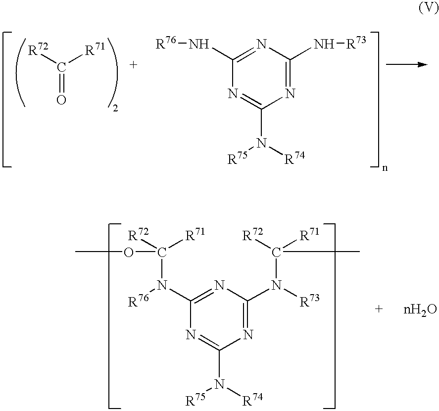
in which each of R71, R72, R73, R74, R75 and R76 is independently hydrogen atom, an alkyl group, an alkenyl group, an aryl group or a heterocyclic group. - The aforementioned definition and examples of substituent group of the alkyl group, the alkenyl group, the aryl group and the heterocyclic group in the formula (III) can be also applied for each of the above groups in the formula (V).
- The polymerization reaction between the carbonyl compound and the melamine compound is the same as an usual synthesis method for known melamine resins (e.g., melamine formaldehyde resin). A commercially available melamine polymer (melamine resin) may be used.
- The melamine polymer preferably has a molecular weight of 2,000 to 400,000.
- At least one of R71, R72, R73, R74, R75 and R76 preferably has an alkylene or alkenylene moiety having 9 to 30 carbon atoms. The alkylene or alkenylene moiety having 9 to 30 carbon atoms preferably has a straight chain structure. The alkylene or alkenylene moiety is preferably included in the substituent group of the aryl group.
- Further, at least one of R71, R72, R73, R74, R75 and R76 preferably has a polymerizable group as a substituent group. The polymerizable group is preferably placed at the terminal end of R71, R72, R73, R74, R75 or R76.
- If the melamine polymer has a polymerizable group, the resultant optically anisotropic layer can contain the discotic liquid crystal molecules polymerized with the melamine polymer.
- The R71, R72, R73, R74, R75 or R76 having a polymerizable group as a substituent group is the same as the aforementioned group represented by the formula (Rp).
- The polymerizable group is introduced into either the carbonyl compound (R71, R72) or the melamine compound (R73, R74, R75, R76). If the melamine compound has the polymerizable group, the carbonyl compound is preferably a compound of simple structure such as formaldehyde. On the other hand, if the carbonyl compound has the polymerizable group, the melamine compound is preferably a compound of simple structure such as non-substituted melamine.
- Examples of the carbonyl compound having a polymerizable group are shown below.

CO-1: R72: —H
R82: —O—(CH2)9—O—CO—CH═CH2
CO-2: R72: —H
R81, R82: —O—(CH2)9—O—CO—CH═CH2
CO-3: R72: —H
R82: —O—(CH2)4—CH═CH—(CH2)4—O—CO—CH═CH2
CO-4: R72: —H
R81, R82: —O—(CH2)4—CH═CH—(CH2)4—O—CO—CH═CH2
CO-5: R72: —H
R81, R83: —O—(CH2)9—O—CO—CH═CH2
CO-6: R72: —H
R81, R82, R83: —O—(CH2)9—O—CO—CH═CH2
CO-7: R72: —CH3
R82: —O—(CH2)9—O—CO—CH═CH2
CO-8: R72: —(CH2)11—CH3
R82: —O—(CH2)4—O—CO—CH═CH2
CO-9: R72: —(CH2)9—O—CO—CH═CH2
R82: —O—(CH2)4—O—CO—CH═CH2
CO-10: R72: —(CH2)9—O—CO—EpEt
R82: —O—(CH2)4—O—CO—CH═CH2
CO-11: R72: —(CH2)4—O—CO—CH═CH2
R81, R83: —O—(CH2)12—CH3
(Remark) Non-defined R: Not substituted (hydrogen atom)
EpEt: epoxyethyl
CO-12: R81, R82, R83, R84: —O—(CH2)6—O—CO—CH═CH2
CO-13: R82, R83: —O—(CH2)9—O—CO—CH═CH2
(Remark) Non-defined R: Not substituted (hydrogen atom)
CO-14: R71: —(CH2)9—O—CO—CH═CH2
R72: —H
CO-15: R71: —(CH2)4—CH═CH—(CH2)4—O—CO—CH═CH2
R72: —H
CO-16: R71: —(CH2)9—O—CO—CH═CH2
R72: —CH3
CO-17: R71: —(CH2)4—CH═CH—(CH2)4—O—CO—CH═CH2
R72: —CH3
CO-18: R71: —(CH2)9—O—CO—CH═CH2
R72: -Ph
CO-19: R71: —(CH2)4—CH═CH—(CH2)4—O—CO—CH═CH2
R72: -Ph
CO-20: R71: —(CH2)4—O—CO—CH═CH2
R72: —(CH2)9—O—CO—CH═CH2
CO-21: R71: —(CH2)4—O—CO—CH═CH2
R72: —(CH2)12—CH3
CO-22: R71: —(CH2)9—O—EpEt
R72: —H
CO-23: R71: —(CH2)4—CH═CH—(CH2)4—O—EpEt
R72: —H
CO-24: R71, R72: —(CH2)9—O—EpEt
CO-25: R71, R72: —(CH2)9—O—CO—CH═CH2
CO-26: R71, R72: —(CH2)4—CH═CH—(CH2)4—O—CO—CH═CH2
(Remark) Ph: phenyl
EpEt:epoxyethyl - Examples of the melamine polymer having a polymerizable group at the melamine moiety are shown below.

MP-1: R73, R75, R76: —CH2—NH—CO—CH═CH2
R74: —CH2—NH—CO—(CH2)8—CH3
MP-2: R71: —CH3
R73, R75, R76: —CH2—NH—CO—CH═CH2
R74: —CH2—NH—CO—(CH2)8—CH3
MP-3: R71, R72: —CH3
R73, R75, R76: —CH2—NH—CO—CH═CH2
R74: —CH2—NH—CO—(CH2)8—CH3
MP-4: R71: -Ph
R73, R75, R76: —CH2—NH—CO—CH═CH2
R74: —CH2—NH—CO—(CH2)8—CH3
MP-5: R73, R76: —CH2—NH—CO—CH═CH2
R74: —CH2—NH—CO—(CH2)7—CH═CH—(CH2)7—CH3
R75: —CH2—O—CH3
MP-6: R73, R76: —CH2—NH—CO—CH═CH2
R74: —CH2—NH—CO—(CH2)7—CH═CH—(CH2)7—CH3
R75: —CH2—OH
MP-7: R73, R76: —CH2—NH—CO—C2H5
R74: —CH2—NH—CO— (CH2)16—CH3
R75: —CH2—O—CH3
MP-8: R73, R76: —CH2—NH—CO—C2H5
R74: —CH2—NH—CO—(CH2)16—CH3
R75: —CH2—OH
MP-9: R73, R76: —CH2—O—CO—CH═CH2
R74: —CH2—O—CO— (CH2)7—CH═CH—(CH2)7—CH3
R75: —CH2—O—CH3
MP-10: R73, R76: —CH2—O—CO—CH═CH2
R74: —CH2—O—CO—(CH2)7—CH═CH—(CH2)7—CH3
R75: —CH2—OH
MP-11: R73, R76: —CH2—O—CO—(CH2)7—CH═CH—(CH2)7—CH3
R74: —CH2—NH—CO— (CH2)7—CH═CH—(CH2)7—CH3
R75: —CH2—O—CH3
MP-12: R73, R76: —CH2—O—CO—(CH2)7—CH═CH—(CH2)7—CH3
R74: —CH2—NH—CO—(CH2)7—CH═CH—(CH2)7—CH3
R75: —CH2—OH
MP-13: R73, R74, R75, R76: —CH2—O—(CH2)11—O—CO—CH═CH2
MP-14: R73, R75, R76: —CH2—NH—CO—CH═CH2
R74: —CH2—O—(CH2)16—CH3
(Remark) Non-defined R: Not substituted (hydrogen atom)
Ph: phenyl - Two or more compounds having 1,3,5-triazine ring (including melamine compounds and melamine polymers) may be used in combination.
- The compound having 1,3,5-triazine ring is used preferably in an amount of 0.01 to 20 wt. %, more preferably in an amount of 0.1 to 15 wt. %, and most preferably in an amount of 0.5 to 10 wt. % based on the amount of the discotic liquid crystal molecules.
- The coating amount of the compound having 1,3,5-triazine ring is preferably in the range of 1 to 1,000 mg/m2, more preferably in the range of 2 to 300 mg/m2, and most preferably in the range of 3 to 100 mg/m2.
- Preferred examples of the rod-like liquid crystal molecules include azomethines, azoxy molecules, cyanobiphenyls, cyanophenyl esters, benzoic esters, phenyl cyclohexanecarbonate esters, cycnophenylcyclohexanes, cyano-substituted phenylpyrimidines, alkoxy-substituted phenylpyrimidines, phenyldioxanes, tolans and alkenylcyclohexylbenzonitriles. Further, some metal complexes can be used as the rod-like liquid crystal molecules.
- Descriptions of the rod-like liquid crystal molecules are found in “Kagaku-Sosetsu, Ekisho no Kageku” (written in Japanese), vol. 22 (1994), Chapters 4, 7 and 11; and “Ekisho Devise Handbook” (written in Japanese), chapter 3.
- The birefringent refractive index of the rod-like liquid crystal molecules is preferably in the range of 0.001 to 0.7. The rod-like liquid crystal molecules preferably have polymerizable groups. Examples of the polymerizable groups are the same as those of the discotic liquid crystal molecules (Q).
- The rod-like liquid crystal molecule preferably has a symmetrical structure about the short axis, and hence preferably has polymerizable groups at both ends.
- Examples of the rod-like liquid crystal molecule are shown below.


- An optically anisotropic layer can be formed by coating an orientation layer with a liquid crystal composition (coating solution) containing the liquid crystal molecules, a polymerization initiator (described below) and optional additives (e.g., plasticizer, monomer, surface active agent, cellulose ester, 1,3,5-triazine compound, chiral agent).
- A solvent for the composition preferably is an organic solvent. Examples of the organic solvents include amides (e.g., N,N-dimethylformamide), sulfoxides (e.g., dimethylsulfoxide), heterocyclic compounds (e.g., pyridine), hydrocarbons (e.g., benzene, hexane), alkyl halides (e.g., chloroform, dichloromethane), esters (e.g., methyl acetate, butyl acetate), ketones (e.g., acetone, methyl ethyl ketone) and ethers (e.g., tetrahydrofuran, 1,2-dimethoxyethane). Alkyl halides and ketones are preferred. Two or more organic solvents can be used in combination.
- The composition can be coated according to a conventional coating method such as a wire-bar coating method, an extrusion coating method, a direct gravure coating method, a reverse gravure coating method or a die coating method.
- The polymerization reaction can be classified into a thermal reaction with a thermal polymerization initiator and a photo reaction with a photo polymerization initiator. A photo polymerization reaction is preferred.
- Examples of the photo polymerization initiators include α-carbonyl compounds (described in U.S. Pat. Nos. 2,367,661, 2,367,670), acyloin ethers (described in U.S. Pat. No. 2,448,828), α-hydrocarbon substituted acyloin compounds (described in U.S. Pat. No. 2,722,512), polycyclic quinone compounds (described in U.S. Pat. Nos. 2,951,758, 3,046,127), combinations of triarylimidazoles and p-aminophenyl ketones (described in U.S. Pat. No. 3,549,367), acridine or phenazine compounds (described in Japanese Patent Provisional Publication No. 60(1985)-105667 and U.S. Pat. No. 4,239,850) and oxadiazole compounds (described in U.S. Pat. No. 4,212,970).
- The amount of the photo polymerization initiator is preferably in the range of 0.01 to 20 wt. %, and more preferably in the range of 0.5 to 5 wt. % based on the solid content of the coating solution.
- The light irradiation for the photo polymerization is preferably conducted with an ultraviolet ray.
- The exposure energy is preferably in the range of 20 to 50,000 mJ per cm2, and more preferably in the range of 100 to 800 mJ per cm2. The light irradiation can be conducted while the layer is heated to accelerate the photo polymerization reaction.
- The thickness of the optically anisotropic layer (the thickness of each layer if two or more optical compensatory sheets are provided) is preferably in the range of 0.1 to 20 μm, more preferably in the range of 0.5 to 15 μm, and most preferably in the range of 1 to 10 μm.
- [Transparent Support]
- The transparent support is a polymer film or a glass plate, preferably a polymer film. The term “transparent” means that light transmittance is not less than 80%.
- As the transparent support, an optically isotropic polymer film is generally used. The term “optical isotropic” means that a retardation value in plane (Re) of the film is preferably not more than 10 nm, more preferably not more than 5 nm. A retardation value along the thickness direction (Rth) of the film is preferably not more than 10 nm, more preferably not more than 5 nm. The Re and Rth retardation values are defined by the following formulas:
Re=(nx×ny)×d
Rth=[{(nx+ny)/2}−nz]×d
in which each of nx and ny is a refractive index in plane of the transparent support; nz is a refractive index along the thickness direction of the transparent support; and d is the thickness of the transparent support. - According to mode of the liquid crystal display, there is a case that an optically anisotropic polymer film is used as the transparent support. In that case, the optically anisotropy of the optically anisotropic layer and that of the transparent support cooperatively correspond to (namely, cooperatively compensate) the optically anisotropy of the liquid crystal cell. The optically anisotropic support preferably has an optically uniaxial birefringence or an optically biaxial birefringence. If the support is optically uniaxial, it may be either optically positive (the refractive index parallel to the optical axis is larger than that perpendicular to the optical axis) or optically negative (the refractive index perpendicular to the optical axis is larger than that parallel to the optical axis). In the case that the support is optically biaxial, the values of nx, ny and nz in the above formula are different from each other.
- In the optically anisotropic transparent support, a retardation value in plane (Re) is preferably in the range of 10 to 1,000 nm, more preferably in the range of 20 to 200 nm, and most preferably in the range of 20 to 100 nm. A retardation value along the thickness direction (Rth) is preferably in the range of 10 to 1,000 nm, more preferably in the range of 70 to 500 nm, further preferably in the range of 70 to 300 nm, and most preferably in the range of 70 to 200 nm.
- Materials for the transparent support are determined according to whether it is optically isotropic or optically anisotropic. The optically isotropic transparent support is generally made of glass or cellulose ester. The optically anisotropic transparent support is generally made of synthetic polymers (e.g., polycarbonate, polysulfone, polyethersulfone, polyacrylate, polymethacrylate, norbornene resin). According to European Patent No. 0,911,656 A2, a optically anisotropic cellulose ester film (giving high retardation) can be prepared (1) with a retardation increasing agent, (2) from a cellulose ester having a low acetylation degree or (3) according to the cooling dissolution method.
- The transparent support of polymer film is formed preferably according to the solvent casting method.
- The optically anisotropic transparent support is preferably obtained by stretching a polymer film.
- The optically uniaxial support can be obtained by a normal uniaxial or biaxial stretching.
- The optically biaxial support is preferably produced by unbalance biaxial stretching. The procedure of unbalance biaxial stretching comprises the steps of: stretching a film along one direction to expand by a certain extent (e.g., 3 to 100%, preferably 5 to 30%), and then stretching the film vertically to the direction of the first stretching to expand by a more extent than that in the first stretching (e.g., 6 to 200%, preferably 10 to 90%). In the procedure, the film may be stretched along the two vertical directions at the same time.
- The direction of stretching (direction of high extension in the case of unbalance biaxial stretching) is preferably essentially parallel to the slow axis in plane of the stretched film. Here “essentially parallel” means that the angle between the stretching direction and the slow axis is preferably in the range of less than 10°, more preferably less than 5°, most preferably less than 3°.
- The transparent support has a thickness preferably in the range of 10 to 500 m, and more preferably in the range of 50 to 200 μm.
- The transparent support can be subjected to a surface treatment (e.g., glow discharge treatment, corona discharge treatment, ultraviolet (UV) treatment, flame treatment) to improve adhesion to a layer formed on the support (e.g., adhesive layer, orientation layer, optically anisotropic layer). The support may contain UV absorber.
- An adhesive layer (undercoating layer) can be provided on the transparent support. Japanese Patent Provisional Publication No. 7(1995)-333433 describes the adhesive layer. The adhesive layer has a thickness preferably in the range of 0.1 to 2 μm, more preferably 0.2 to 1 μm.
- [Orientation Layer]
- The orientation layer can be formed by rubbing treatment of an organic compound (preferably a polymer), oblique evaporation of an inorganic compound, formation of a micro groove layer, or stimulation of an organic compound (e.g., ω-tricosanoic acid, dioctadecylmethylammonium chloride, methyl stearate) according to a Langmuir-Blodgett method. Further, the aligning function of the orientation layer can be activated by applying an electric or magnetic field to the layer or irradiating the layer with light. The orientation layer is preferably formed by rubbing a polymer. The rubbing treatment can be conducted by rubbing a polymer layer with paper or cloth several times along a certain direction.
- For aligning the liquid crystal molecules in an average inclined angle of not more than 5°, a polymer which does not lower the surface energy of the orientation layer (namely, a polymer usually used for the orientation layer) is preferred.
- The orientation layer preferably has a thickness of 0.01 to 5 μm, more preferably 0.05 to 1 μm.
- After the liquid crystal molecules are aligned by the orientation layer to form an optically anisotropic layer, the optically anisotropic layer can be transferred to the transparent support. The aligned and fixed liquid crystal molecules can keep the alignment without the orientation layer.
- Alignment in an average inclined angle of less than 5° C. can be obtained without rubbing treatment nor the orientation layer. However, even in that case, an orientation layer which chemically combines with the liquid crystal molecules on the interface can be provided so as to improve adhesion between the molecules and the support (Japanese Patent Provisional Publication No. 9(1997)-152509). Such orientation layer does not need the rubbing treatment.
- In the case that two liquid crystal layers are provided on the same side of the transparent support, the layer beforehand provided on the support can function as the orientation layer for the other layer provided thereon.
- [Polarizing Membrane]
- As the polarizing membrane, various membranes are known. Examples of the polarizing membranes include an iodine polarizing membrane, a polyene polarizing membrane and a dichromatic dye polarizing membrane. The iodine polarizing membrane and the dye polarizing membrane are generally prepared from polyvinyl alcohol films. The polarizing axis of the membrane is perpendicular to the stretching direction of the film.
- The transparent axis in plane of the polarizing membrane is preferably essentially parallel or perpendicular to the direction obtained by projecting the long axes of the rod-like liquid crystal molecules onto the support surface on average.
- [Protective Film]
- A transparent polymer film is used as the transparent protective film. The term “transparent” means that light transmittance is not less than 80%.
- A cellulose acetate film, preferably a triacetyl cellulose film, is generally used. The cellulose acetate film is preferably formed according to the solvent casting method.
- The thickness of the protective film is preferably in the range of 20 to 500 μm, more preferably in the range of 50 to 200 μm.
- [Liquid Crystal Display]
- The present invention can be applied for liquid crystal displays of various modes. Examples of the display modes include TN (twisted nematic) mode, IPS (in plane switching) mode, FLC (ferroelectric liquid crystal) mode, OCB (optically compensatory bend) mode, STN (super twisted nematic) mode, VA (vertically aligned) mode, ECB (electrically controlled birefringence) mode and HAN (hybrid aligned nematic) mode optical compensatory sheets for these modes are known. The optical compensatory sheet of the invention is suitable for a liquid crystal display having a liquid crystal cell of VA mode, OCB mode or HAN mode, in which many rod-like liquid crystal molecules are vertically aligned. The optical compensatory sheet of the invention is particularly suitable for VA mode in which most rod-like liquid crystal molecules are vertically aligned.
- The liquid crystal cell of VA mode include three types:
- (1) a liquid crystal cell of VA mode in a narrow sense (described in Japanese Patent Provisional Publication No. 2(1990)-176625), in which rod-like liquid crystal molecules are essentially vertically aligned while voltage is not applied, and the molecules are essentially horizontally aligned while voltage is applied;
- (2) a liquid crystal cell of MVA mode (described in SID97, Digest of tech. Papers, 28(1997), 845), in which the VA mode is modified to be multi-domain type so as to enlarge the viewing angle;
- (3) a liquid crystal cell of n-ASM mode (described in Nippon Ekisho Toronkai [Liquid crystal forum of Japan], Digest of tech. Papers (1998), 58-59), in which rod-like liquid crystal molecules are essentially vertically aligned while voltage is not applied, and the molecules are essentially oriented in twisted multi-domain alignment while voltage is applied; and
- (4) a liquid crystal cell of SURVAIVAL mode (published in LCD international 98).
- (Preparation of Optical Compensatory Sheet)
- On one surface of a cellulose triacetate film, cellulose diacetate is applied and dried to form an undercoating layer (an orientation layer not subjected to rubbing treatment) of 0.5 μm dry thickness.
- Then, 90 weight parts of the following discotic liquid crystal compound (1), 10 weight parts of ethylene oxide denatured trimethlolpropanetriacrylate (V#360, Osaka Organic Chemicals Co., Ltd.), 0.6 weight part of melamine formaldehyde/acrylic acid copolymer (Aldrich), 3.0 weight parts of a photopolymerization initiator (Irgacure 907, Ciba-Geigy) and 1 weight part of a sensitizer (Kayacure DETX, Nippon Kayaku Co., Ltd.) were dissolved in methyl ethyl ketone to prepare a coating solution [solid content: 38 wt. %].

- The coating solution was applied and dried on the undercoating layer. Immediately after the applied solution was heated at 130° C. for 2 minutes to align the discotic liquid crystal molecules, the solution was cooled to room temperature and irradiated with ultraviolet light (500 mJ/cm2) to polymerize the discotic liquid crystal molecules. Thus, the alignment of the discotic liquid crystal molecules was fixed to form an optically anisotropic layer of 1.7 μm thickness.
- The angle dependence of retardation of the optically anisotropic layer was measured by means of an ellipsometer [M-150, JASCO], and thereby the inclined angle and the Rth (retardation value along the thickness direction) were found 0.2° and 88 nm, respectively.
- On the other surface of the cellulose triacetate film, an optically uniaxial polycarbonate film was laminated with an adhesive to prepare an optical compensatory sheet.
- The optically uniaxial polycarbonate film had an optical axis in the plane. The retardation value in plane (Re) and the retardation value along the thickness direction (Rth) were 50 nm and 30 nm, respectively.
- The Re and Rth of the prepared optical compensatory sheet were 50 nm and 100 nm, respectively. (Preparation of elliptically polarizing plate) A polarizing membrane and a transparent protective film were overlaid in this order on the transparent support (polycarbonate film) side of the optical compensatory sheet, to prepare an elliptically polarizing plate.
- The polarizing membrane was placed so that the slow axis of the support might be parallel to the polarizing axis of the membrane.
- (Preparation of Liquid Crystal Display)
- From a commercially available liquid crystal display of VA mode [LCD 5000], an elliptically polarizing plate was peeled. In place of it, the above-prepared elliptically polarizing plate was laminated.
- With respect to the prepared display, the contrast data in all directions were measured. The viewing angle giving a contrast ratio of 20:1 was 160° (upward-downward-rightward-leftward). On the other hand, the viewing angle giving a contrast ratio of 20:1 in the commercially available liquid crystal display was 120° (upward-downward-rightward-leftward).
- (Preparation of Optically Biaxial Transparent Support)
- 87 Weight parts of cellulose triacetate, 10 weight parts of triphenyl phosphate and 3 weight parts of UV absorber (TM165, Sumitomo Chemical Co., Ltd.) were dissolved in methylene chloride, to prepare a solution [solid content: 18 wt. %]. The solution was cast on a glass plate, and dried at 40° C. for 20 minutes to form a film. The formed film (thickness: 100 μm) was peeled off the glass plate.
- Onto the formed cellulose triacetate film, a stress of 20 kg/mm2 was applied at 145° C. for 10 minutes. Thus, an optically biaxial transparent support having Re of 20 nm and Rth of 80 nm was prepared.
- (Preparation of Optical Compensatory Sheet)
- The coating solution for optically anisotropic layer used in Example 1 was applied on the optically biaxial transparent support in the amount of 3 ml/m2, and dried at room temperature. The applied solution was heated at 130° C. for 1 minute to align the discotic liquid crystal molecules, and irradiated with ultraviolet light to polymerize the discotic liquid crystal molecules. Thus, the alignment of the discotic liquid crystal molecules was fixed.
- The angle dependence of retardation of the optically anisotropic layer was measured by means of an ellipsometer [M-150, JASCO], and thereby the inclined angle was found 0.1°. The Re and Rth of the prepared optical compensatory sheet were 20 nm and 140 nm, respectively.
- (Preparation of Elliptically Polarizing Plate)
- A polarizing membrane and a transparent protective film were overlaid in this order on the transparent support side of the optical compensatory sheet, to prepare a elliptically polarizing plate.
- The polarizing membrane was placed so that the slow axis of the support might be parallel to the polarizing axis of the membrane.
- (Preparation of Liquid Crystal Display)
- From a commercially available liquid crystal display of VA mode [LCD 5000], an elliptically polarizing plate was peeled. In place of it, the above-prepared elliptically polarizing plate was laminated.
- With respect to the prepared display, the contrast data in all directions were measured. The viewing angle giving a contrast ratio of 20:1 was 160° (upward-downward-rightward-leftward).
- (Preparation of Optically Biaxial Transparent Support)
- 85 Weight parts of cellulose triacetate, 10 weight parts of triphenyl phosphate and 5 weight parts of UV absorber (TM165, Sumitomo Chemical Co., Ltd.) were dissolved in methylene chloride, to prepare a solution [solid content: 18 wt. %]. The solution was cast on a glass plate, and dried at 40° C. for 20 minutes to form a film. The formed film (thickness: 100 μm) was peeled off the glass plate.
- Onto the formed cellulose triacetate film, a stress of 20 kg/mm2 was applied at 145° C. for 10 minutes. Thus, an optically biaxial transparent support having Re of 50 nm and Rth of 120 nm was prepared.
- (Preparation of Optical Compensatory Sheet)
- The coating solution for optically anisotropic layer used in Example 1 was applied on the optically biaxial transparent support in the amount of 6 ml/m2, and dried at room temperature. The applied solution was heated at 130° C. for 1 minute to align the discotic liquid crystal molecules, and irradiated with ultraviolet light to polymerize the discotic liquid crystal molecules. Thus, the alignment of the discotic liquid crystal molecules was fixed.
- The angle dependence of retardation of the optically anisotropic layer was measured by means of an ellipsometer [M-150, JASCO], and thereby the inclined angle was found 0.5°. The Re and Rth of the prepared optical compensatory sheet were 50 nm and 250 nm, respectively.
- (Preparation of Elliptically Polarizing Plate)
- A polarizing membrane and a transparent protective film were overlaid in this order on the transparent support side of the optical compensatory sheet, to prepare a elliptically polarizing plate.
- The polarizing membrane was placed so that the slow axis of the support might be parallel to the polarizing axis of the membrane.
- (Preparation of Liquid Crystal Display)
- From a commercially available liquid crystal display of VA mode [LCD 5000], an elliptically polarizing plate was peeled. In place of it, the above-prepared elliptically polarizing plate was laminated.
- With respect to the prepared display, the contrast data in all directions were measured. The viewing angle giving a contrast ratio of 20:1 was 160° (upward-downward-rightward-leftward).
- (Preparation of Optically Biaxial Transparent Support)
- 45 Weight parts of cellulose acetate (average acetylation degree: 60.9%), 2.35 weight parts of the following retardation increasing agent, 2.75 weight parts of triphenyl phosphate and 2.20 weight parts of biphenyldiphenyl phosphate were dissolved in a mixed solvent comprising 232.75 weight parts of methylene chloride, 42.57 weight parts of methanol and 8.50 weight parts of n-butanol. The solution was cast on a drum to form a cellulose acetate film (dry thickness: 105 μm).

- The cellulose acetate film was stretched by 20%, to prepare an optically biaxial transparent support.
- The retardation values of Rth and Re of the obtained cellulose acetate film were measured at 633 nm by means of an ellipsometer [M-150, JASCO], and thereby the values of Rth and Re were found 85 nm and 40 nm, respectively.
- (Preparation of Optical Compensatory Sheet)
- On one surface of the transparent support, gelatin was applied to form an undercoating layer.
- An aqueous solution containing the following denatured polyvinyl alcohol (2 wt. %) and glutaric aldehyde (0.1 wt. %) was applied on the undercoating layer, and the applied solution was dried to form an orientation layer of 0.5 μm thickness.

- Then, 90 weight parts of the discotic liquid crystal compound (1) used in Example 1, 10 weight parts of ethylene oxide denatured trimethlolpropanetriacrylate (V#360, Osaka Organic Chemicals Co., Ltd.), 0.6 weight part of melamine formaldehyde/acrylic acid copolymer (Aldrich), 3.0 weight parts of a photopolymerization initiator (Irgacure 907, Ciba-Geigy) and 1.0 weight part of a sensitizer (Kayacure DETX, Nippon Kayaku Co., Ltd.) were dissolved in 170 weight parts of methyl ethyl ketone to prepare a coating solution.
- The coating solution was applied and dried on the orientation layer. The applied solution was heated at 130° C. for 1 minute to align the discotic liquid crystal molecules, and then irradiated with ultraviolet light (500 mJ/cm2) to polymerize the discotic liquid crystal molecules. Thus, the alignment of the discotic liquid crystal molecules was fixed to form an optically anisotropic layer of 1.2 μm thickness.
- The retardation values of Re and Rth of the obtained cellulose acetate film were measured at 633 nm by means of an ellipsometer [M-150, JASCO], and thereby the values of Re and Rth were found 40 nm and 160 nm, respectively.
- (Preparation of Elliptically Polarizing Plate)
- A polarizing membrane and a transparent protective film were overlaid in this order on the transparent support side of the optical compensatory sheet, to prepare a elliptically polarizing plate.
- The polarizing membrane was placed so that the slow axis of the support might be parallel to the polarizing axis of the membrane.
- (Preparation of Liquid Crystal Display)
- From a commercially available liquid crystal display of MVA mode [VL-1530S, Fujitsu Ltd.], a polarizing plate was peeled. In place of it, the above-prepared elliptically polarizing plate was laminated.
- With respect to the prepared display, the viewing angle giving a contrast ratio of 10:1 without image inversion was measured. The results are set forth in Table 1.
- (Preparation of Optically Biaxial Transparent Support)
- In 70 weight parts of methylene chloride, 30 weight parts of norbornene resin (Artone, JSR Co., Ltd.) was dissolved. The solution was cast on a band, and dried to form a norbornene film (dry thickness: 100 μm).
- The film was longitudinally stretched by 15%, and then laterally stretched by 7% to prepare an optically biaxial transparent support.
- The retardation values of Rth and Re of the obtained support were measured at 633 nm by means of an ellipsometer [M-150, JASCO], and thereby the values of Rth and Re were found 45 nm and 40 nm, respectively.
- (Preparation of Optical Compensatory Sheet)
- One surface of the transparent support was subjected to the corona discharge treatment. On the treated surface, an aqueous solution containing the denatured polyvinyl alcohol used in Example 4 (2 wt. %) and glutaric aldehyde (0.1 wt. %) was applied. The applied solution was dried to form an orientation layer of 0.5 μm thickness.
- Then, 90 weight parts of the discotic liquid crystal compound (1) used in Example 1, 10 weight parts of ethylene oxide denatured trimethlolpropanetriacrylate (V#360, Osaka Organic Chemicals Co., Ltd.), 0.6 weight part of melamine formaldehyde/acrylic acid copolymer (Aldrich), 3.0 weight parts of a photopolymerization initiator (Irgacure 907, Ciba-Geigy) and 1.0 weight part of a sensitizer (Kayacure DETX, Nippon Kayaku Co., Ltd.) were dissolved in 170 weight parts of methyl ethyl ketone to prepare a coating solution.
- The coating solution was applied and dried on the orientation layer. The applied solution was heated at 130° C. for 1 minute to align the discotic liquid crystal molecules, and then irradiated with ultraviolet light to polymerize the discotic liquid crystal molecules. Thus, the alignment of the discotic liquid crystal molecules was fixed to form an optically anisotropic layer of 1.4 μm thickness.
- The retardation values of Re and Rth of the obtained cellulose acetate film were measured at 633 nm by means of an ellipsometer [M-150, JASCO], and thereby the values of Re and Rth were found 30 nm and 120 nm, respectively.
- (Preparation of Elliptically Polarizing Plate)
- A polarizing membrane and a transparent protective film were overlaid in this order on the transparent support side of the optical compensatory sheet, to prepare a elliptically polarizing plate.
- The polarizing membrane was placed so that the slow axis of the support might be parallel to the polarizing axis of the membrane.
- (Preparation of Liquid Crystal Display)
- From a commercially available liquid crystal display of MVA mode [VL-1530S, Fujitsu Ltd.], a polarizing plate was peeled. In place of it, the above-prepared elliptically polarizing plate was laminated.
- With respect to the prepared display, the viewing angle giving a contrast ratio of 10:1 without image inversion was measured. The results are set forth in Table 1.
- (Preparation of Optically Biaxial Transparent Support)
- A commercially available polycarbonate film (Teijin Limited) was longitudinally stretched by 40%, and then laterally stretched by 15% to prepare an optically biaxial transparent support.
- The retardation values of Rth and Re of the obtained support were measured at 633 nm by means of an ellipsometer [M-150, JASCO], and thereby the values of Rth and Re were found 100 nm and 200 nm, respectively.
- (Preparation of Optical Compensatory Sheet)
- One surface of the transparent support was subjected to the corona discharge treatment. On the treated surface, an aqueous solution containing the denatured polyvinyl alcohol used in Example 4 (2 wt. %) and glutaric aldehyde (0.1 wt. %) was applied. The applied solution was dried to form an orientation layer of 0.5 μm thickness.
- Then, 90 weight parts of the discotic liquid crystal compound (1) used in Example 1, 10 weight parts of ethylene oxide denatured trimethlolpropanetriacrylate (V#360, Osaka Organic Chemicals Co., Ltd.), 0.6 weight part of melamine formaldehyde/acrylic acid copolymer (Aldrich), 3.0 weight parts of a photopolymerization initiator (Irgacure 907, Ciba-Geigy) and 1.0 weight part of a sensitizer (Kayacure DETX, Nippon Kayaku Co., Ltd.) were dissolved in 170 weight parts of methyl ethyl ketone to prepare a coating solution.
- The coating solution was applied and dried on the orientation layer. The applied solution was heated at 130° C. for 1 minute to align the discotic liquid crystal molecules, and then irradiated with ultraviolet light to polymerize the discotic liquid crystal molecules. Thus, the alignment of the discotic liquid crystal molecules was fixed to form an optically anisotropic layer of 3.5 μm thickness.
- The retardation values of Re and Rth of the obtained optical compensatory sheet were measured at 633 nm by means of an ellipsometer.[M-150, JASCO], and thereby the values of Re and Rth were found 200 nm and 300 nm, respectively.
- (Preparation of Elliptically Polarizing Plate)
- A polarizing membrane and a transparent protective film were overlaid in this order on the transparent support side of the optical compensatory sheet, to prepare a elliptically polarizing plate.
- The polarizing membrane was placed so that the slow axis of the support might be parallel to the polarizing axis of the membrane.
- (Preparation of Liquid Crystal Display)
- From a commercially available liquid crystal display of MVA mode [VL-1530S, Fujitsu Ltd.], a polarizing plate was peeled. In place of it, the above-prepared elliptically polarizing plate was laminated.
- With respect to the prepared display, the viewing angle giving a contrast ratio of 10:1 without image inversion was measured. The results are set forth in Table 1.
- (Preparation of Optically Isotropic Transparent Support)
- A commercially available cellulose triacetate film (Fuji Photo Film Co., Ltd.) was used as a transparent support.
- The retardation values of Rth and Re of the support were measured at 633 nm by means of an ellipsometer [M-150, JASCO], and thereby the values of Rth and Re were found 40 nm and 3 nm, respectively. This meant that the support was essentially isotropic.
- (Preparation of Optical Compensatory Sheet)
- On one surface of the transparent support, gelatin was applied to form an undercoating layer. On the undercoating layer, an aqueous solution containing the denatured polyvinyl alcohol used in Example 4 (2 wt. %) and glutaric aldehyde (0.1 wt. %) was applied. The applied solution was dried to form an orientation layer of 0.5 μm thickness.
- Then, 90 weight parts of the discotic liquid crystal compound (1) used in Example 1, 10 weight parts of ethylene oxide denatured trimethlolpropanetriacrylate (V#360, Osaka Organic Chemicals Co., Ltd.), 0.6 weight part of melamine formaldehyde/acrylic acid copolymer (Aldrich), 3.0 weight parts of a photopolymerization initiator (Irgacure 907, Ciba-Geigy) and 1.0 weight part of a sensitizer (Kayacure DETX, Nippon Kayaku Co., Ltd.) were dissolved in 170 weight parts of methyl ethyl ketone to prepare a coating solution.
- The coating solution was applied and dried on the orientation layer. The applied solution was heated at 130° C. for 1 minute to align the discotic liquid crystal molecules, and then irradiated with ultraviolet light to polymerize the discotic liquid crystal molecules. Thus, the alignment of the discotic liquid crystal molecules was fixed to form an optically anisotropic layer of 2.0 μm thickness.
- The retardation values of Re and Rth of the obtained cellulose acetate film were measured at 633 nm by means of an ellipsometer [M-150, JASCO], and thereby the values of Re and Rth were found 3 nm and 240 nm, respectively.
- (Preparation of Elliptically Polarizing Plate)
- A polarizing membrane and a transparent protective film were overlaid in this order on the transparent support side of the optical compensatory sheet, to prepare a elliptically polarizing plate.
- The polarizing membrane was placed so that the slow axis of the support might be parallel to the polarizing axis of the membrane.
- (Preparation of Liquid Crystal Display)
- From a commercially available liquid crystal display of MVA mode [VL-1530S, Fujitsu Ltd.], a polarizing plate was peeled. In place of it, the above-prepared elliptically polarizing plate was laminated.
- With respect to the prepared display, the viewing angle giving a contrast ratio of 10:1 without image inversion was measured. The results are set forth in Table 1.
- With respect to a commercially available liquid crystal display of MVA mode [VL-1530S, Fujitsu Ltd.], the viewing angle giving a contrast ratio of 10:1 without image inversion was measured. The results are set forth in Table 1.
TABLE 1 Retardation of optically MVA liquid compensatory sheet Viewing angle crystal display Re Rth (1) (2) Example 4 40 nm 160 nm 80° 80° Example 5 30 nm 120 nm 80° 75° Example 6 200 nm 300 nm 80° 60° Comp. Ex. 1 3 nm 240 nm 80° 55° Ref. Ex. 1 None 80° 45°
Remarks:
(1) upward-downward-rightward-leftward
(2) obliquely upward-downward-rightward-leftward
- (Preparation of First Undercoating Layer/Transparent Support/Second Undercoating Layer)
- A cellulose triacetate film was used as a transparent support.
- On one surface of the support, cellulose diacetate was applied to form a first undercoating layer.
- On the other surface, gelatin was applied to form a second undercoating layer.
- (Preparation of First Undercoating Layer/Transparent Support/Second Undercoating Layer/Orientation Layer)
- On the second undercoating layer, an aqueous solution containing polyvinyl alcohol (Poparl MP203, Kuraray Co., Ltd.) in the amount of 2 wt. % was applied and dried. The formed layer was subjected to the rubbing treatment to prepare an orientation layer of 0.5 μm thickness.
- (Preparation of First Optically Anisotropic Layer/First Undercoating Layer/Transparent Support/Second Undercoating Layer/Orientation Layer)
- 90 Weight parts of the discotic liquid crystal compound (1) used in Example 1, 10 weight parts of ethylene oxide denatured trimethlolpropanetriacrylate (V#360, Osaka organic Chemicals Co., Ltd.), 0.6 weight part of melamine formaldehyde/acrylic acid copolymer (Aldrich), 3.0 weight parts of a photopolymerization initiator (Irgacure 907, Ciba-Geigy) and 1.0 weight part of a sensitizer (Kayacure DETX, Nippon Kayaku Co., Ltd.) were dissolved in methyl ethyl ketone to prepare a coating solution (solid content: 38 wt. %).
- The coating solution was applied and dried on the first undercoating layer. Immediately after the applied solution was heated at 130° C. for 2 minutes to align the discotic liquid crystal molecules, the solution was cooled to room temperature and irradiated with ultraviolet light (500 mJ/cm2) to polymerize the discotic liquid crystal molecules. Thus, the alignment of the discotic liquid crystal molecules was fixed to form a first optically anisotropic layer of 1.7 μm thickness.
- The angle dependence of retardation of the first optically anisotropic layer was measured by means of an ellipsometer [M-150, JASCO], and thereby the inclined angle and the Rth (retardation value along the thickness direction) were found 0.2° and 88 nm, respectively.
- (Preparation of Optical Compensatory Sheet Consisting of First Optically Anisotropic Layer/First Undercoating Layer/Transparent Support/Second Undercoating Layer/Orientation Layer/Second Optically Anisotropic Layer)
- 90 Weight parts of rod-like liquid crystal compound (N26), 10 weight parts of ethylene oxide denatured trimethlolpropanetriacrylate (V#360, Osaka Organic Chemicals Co., Ltd.), 3.0 weight parts of a photopolymerization initiator (Irgacure 907, Ciba-Geigy) and 1.0 weight part of a sensitizer (Kayacure DETX, Nippon Kayaku Co., Ltd.) were dissolved in methyl ethyl ketone to prepare a coating solution (solid content: 38 wt. %).
- The coating solution was applied and dried on the orientation layer. Immediately after the applied solution was heated at 130° C. for 2 minutes to align the rod-like liquid crystal molecules, the solution was cooled to room temperature and irradiated with ultraviolet light (500 mJ/cm2) to polymerize the rod-like liquid crystal molecules. Thus, the alignment of the rod-like liquid crystal molecules was fixed to form a second optically anisotropic layer of 0.5 μm thickness.
- Thus, an optical compensatory sheet was prepared.
- Independently, with respect to the second optically anisotropic layer in the layered structure of first undercoating layer/transparent support/second undercoating layer/orientation layer/second optically anisotropic layer, the angle dependence of retardation was measured by means of an ellipsometer [M-150, JASCO]. As a result, the Re (retardation value in plane) was 50 nm. This meant that the rod-like liquid crystal molecules were oriented in a horizontal (homogeneous) alignment.
- Further, the retardation values of Re and Rth of the obtained optical compensatory sheet were measured at 633 nm by means of an ellipsometer [M-150, JASCO], and thereby the values of Re and Rth were found 40 nm and 130 nm, respectively.
- (Preparation of Elliptically Polarizing Plate Consisting of First Optically Anisotropic Layer/First Undercoating Layer/Transparent Support/Second Undercoating Layer/Orientation Layer/Second Optically Anisotropic Layer/Polarizing Membrane/Transparent Protective Film)
- A polarizing membrane and a transparent protective film were overlaid in this order on the transparent support side of the optical compensatory sheet, to prepare a elliptically polarizing plate.
- The polarizing membrane was placed so that the polarizing axis of the membrane might be parallel to the optical axis (average line obtained by projecting the long axes of rod-like liquid crystal molecules onto the transparent support on average) of the second optically anisotropic layer.
- (Preparation of Liquid Crystal Display)
- From a commercially available liquid crystal display of VA mode [LCD 5000], an elliptically polarizing plate was peeled. In place of it, the above-prepared elliptically polarizing plate was laminated.
- With respect to the prepared display, the contrast data along all directions were measured. The viewing angle giving a contrast ratio of 20:1 was 160° (upward-downward-rightward-leftward). On the other hand, the viewing angle giving a contrast ratio of 20:1 in the commercially available liquid crystal display was 120° (upward-downward-rightward-leftward).
- Immediately after the liquid crystal display was turned on, the displayed image was observed. The display kept displaying the image for 2 hours, and then the image was observed again to compare defects of the image with those of the initial image. As a result, there was no change between them.
- (Preparation of Transparent Support/Undercoating Layer)
- A cellulose triacetate film was used as a transparent support.
- On one surface of the support, cellulose diacetate was applied to form an undercoating layer of 0.5 μm thickness.
- (Preparation of Transparent Support/Undercoating Layer/First Optically Anisotropic Layer)
- 90 Weight parts of the discotic liquid crystal compound (1) used in Example 1, 10 weight parts of ethylene oxide denatured trimethlolpropanetriacrylate (V#360, Osaka Organic Chemicals Co., Ltd.), 0.6 weight part of melamine formaldehyde/acrylic acid copolymer (Aldrich), 3.0 weight parts of a photopolymerization initiator (Irgacure 907, Ciba-Geigy) and 1.0 weight part of a sensitizer (Kayacure DETX, Nippon Kayaku Co., Ltd.) were dissolved in methyl ethyl ketone to prepare a coating solution (solid content: 38 wt. %).
- The coating solution was applied and dried on the undercoating layer. Immediately after the applied solution was heated at 130° C. for 2 minutes to align the discotic liquid crystal molecules, the solution was cooled to room temperature and irradiated with ultraviolet light (500 mJ/cm2) to polymerize the discotic liquid crystal molecules. Thus, the alignment of the discotic liquid crystal molecules was fixed to form a first optically anisotropic layer of 1.7 μm thickness.
- (Preparation of Optical Compensatory Sheet Consisting of Transparent Support/Undercoating Layer/First Optically Anisotropic Layer/Second Optically Anisotropic Layer)
- 90 weight parts of rod-like liquid crystal compound (N26), 10 weight parts of ethylene oxide denatured trimethlolpropanetriacrylate (V#360, Osaka Organic Chemicals Co., Ltd.), 3.0 weight parts of a photopolymerization initiator (Irgacure 907, Ciba-Geigy) and 1.0 weight part of a sensitizer (Kayacure DETX, Nippon Kayaku Co., Ltd.) were dissolved in methyl ethyl ketone to prepare a coating solution (solid content: 38 wt. %).
- After a surface of the first optically anisotropic layer was subjected to the rubbing treatment, the coating solution was applied and dried on the treated surface. Immediately after the applied solution was heated at 130° C. for 2 minutes to align the rod-like liquid crystal molecules, the solution was cooled to room temperature and irradiated with ultraviolet light (500 mJ/cm2) to polymerize the rod-like liquid crystal molecules. Thus, the alignment of the rod-like liquid crystal molecules was fixed to form a second optically anisotropic layer of 0.5 μm thickness.
- Thus, an optical compensatory sheet was prepared.
- The retardation values of Re and Rth of the obtained optical compensatory sheet were measured at 633 nm by means of an ellipsometer [M-150, JASCO], and thereby the values of Re and Rth were found 40 nm and 130 nm, respectively.
- (Preparation of Elliptically Polarizing Plate Consisting of Transparent Protective Film/Polarizing Membrane/Transparent Support/Undercoating Layer/First Optically Anisotropic Layer/Second Optically Anisotropic Layer)
- A polarizing membrane and a transparent protective film were overlaid in this order on the optical compensatory sheet, to prepare a elliptically polarizing plate.
- The polarizing membrane was placed so that the polarizing axis of the membrane might be parallel to the optical axis (average line obtained by projecting the long axes of rod-like liquid crystal molecules onto the transparent support on average) of the second optically anisotropic layer.
- (Preparation of Liquid Crystal Display)
- From a commercially available liquid crystal display of VA mode [LCD 5000], an elliptically polarizing plate was peeled. In place of it, the above-prepared elliptically polarizing plate was laminated.
- With respect to the prepared display, the contrast data in all directions were measured. The viewing angle giving a contrast ratio of 20:1 was 160° (upward-downward-rightward-leftward). On the other hand, the viewing angle giving a contrast ratio of 20:1 in the commercially available liquid crystal display was 120° (upward-downward-rightward-leftward).
- (Preparation of transparent Support/Undercoating Layer)
- A cellulose acetate (average acetylation degree: 60.9%) film was used as a transparent support.
- On one surface of the support, gelatin was applied to form an undercoating layer.
- (Preparation of transparent Support/Undercoating Layer/Orientation Layer)
- On the undercoating layer, an aqueous solution containing the denatured polyvinyl alcohol used in Example 4 (2 wt. %) and glutaric aldehyde (0.1 wt. %) was applied and dried. The formed layer was subjected to the rubbing treatment to prepare an orientation layer of 0.5 μm thickness.
- (Preparation of Optical Compensatory Sheet Consisting of Transparent Support/Undercoating Layer/Orientation layer/Optically Anisotropic Layer)
- 80 Weight parts of the discotic liquid crystal compound (1) used in Example 1, 10 weight parts of rod-like liquid crystal compound (N26), 10 weight parts of ethylene oxide denatured trimethlolpropanetriacrylate (V#360, Osaka Organic Chemicals Co., Ltd.), 0.6 weight part of melamine formaldehyde/acrylic acid copolymer (Aldrich), 3.0 weight parts of a photopolymerization initiator (Irgacure 907, Ciba-Geigy) and 1.0 weight part of a sensitizer (Kayacure DETX, Nippon Kayaku Co., Ltd.) were dissolved in 170 weight parts of methyl ethyl ketone to prepare a coating solution.
- The coating solution was applied and dried on the orientation layer. The applied solution was heated at 130° C. for 1 minute to align the discotic and rod-like liquid crystal molecules, and then irradiated with ultraviolet light to polymerize the discotic and rod-like liquid crystal molecules. Thus, the alignment of the discotic and rod-like liquid crystal molecules was fixed to form an optically anisotropic layer of 1.2 μm thickness.
- The retardation values of Rth and Re of the obtained optical compensatory sheet were measured at 633 nm by means of an ellipsometer [M-150, JASCO], and thereby the values of Rth and Re were found 160 nm and 40 nm, respectively.
- (Preparation of Optically Biaxial Transparent Support)
- 45 Weight parts of cellulose acetate (average acetylation degree: 60.9%), 2.35 weight parts of the retardation increasing agent used in Example 4, 2.75 weight parts of triphenyl phosphate and 2.20 weight parts of biphenyldiphenyl phosphate were dissolved in a mixed solvent comprising 232.75 weight parts of methylene chloride, 42.57 weight parts of methanol and 8.50 weight parts of n-butanol. The solution was cast on a drum to form a cellulose acetate film (dry thickness: 105 μm).
- The cellulose acetate film was stretched by 20%, to prepare an optically biaxial transparent support.
- The retardation values of Rth and Re of the obtained cellulose acetate film were measured at 633 nm by means of an ellipsometer [M-150, JASCO], and thereby the values of Rth and Re were found 85 nm and 40 nm, respectively.
- (Preparation of Optical Compensatory Sheet)
- One surface of the transparent support was subjected to the corona discharge treatment. On the treated surface, a solution of 2 wt. % denatured polyimide (Nissan Chemicals Co., Ltd.) was applied. The applied solution was dried to form an orientation layer of 0.5 μm thickness. A surface of the orientation layer was subjected to the rubbing treatment.
- 20 weight parts of acrylic theromotropic liquid crystal polymer was dissolved in 80 weight parts of tetrachloroethylene to prepare a coating solution.
- The solution was applied on the orientation layer, heated at 160° C. for 5 minutes and cooled to room temperature, to fix the alignment of the liquid crystal molecules. Thus, an optically anisotropic layer of 1.5 μm thickness was formed.
- The retardation values of Re and Rth of the obtained optical compensatory sheet were measured at 633 nm by means of an ellipsometer [M-150, JASCO], and thereby the values of Re and Rth were found 40 nm and 240 nm, respectively.
- (Preparation of Elliptically Polarizing Plate)
- A polarizing membrane and a transparent protective film were overlaid in this order on the transparent support side of the optical compensatory sheet, to prepare a elliptically polarizing plate.
- The polarizing membrane was placed so that the slow axis of the support might be parallel to the polarizing axis of the membrane.
- (Preparation of Liquid Crystal Display)
- From a commercially available liquid crystal display of MVA mode [VL-1530S, Fujitsu Ltd.], a polarizing plate was peeled. In place of it, the above-prepared elliptically polarizing plate was laminated.
- With respect to the prepared display, the viewing angle giving a contrast ratio of 10:1 without image inversion was measured. As a result, although the upward-downward-rightward-leftward viewing angle was 80° (which was the same as that of the commercially available liquid crystal display), the obliquely upward-downward-rightward-leftward viewing angle was 60° (while that of the commercially available liquid crystal display was 45°).
- (Preparation of Optically Biaxial Transparent Support)
- In 70 weight parts of methylene chloride, 30 weight parts of norbornene resin (Artone, JSR Co., Ltd.) was dissolved. The solution was cast on a band, and dried to form a norbornene film (dry thickness: 100 μm).
- The film was longitudinally stretched by 15%, and then laterally stretched by 7% to prepare an optically biaxial transparent support.
- The retardation values of Rth and Re of the obtained support were measured at 633 nm by means of an ellipsometer [M-150, JASCO], and thereby the values of Rth and Re were found 45 nm and 40 nm, respectively.
- (Preparation of Optical Compensatory Sheet)
- One surface of the transparent support was subjected to the corona discharge treatment. On the treated surface, an aqueous solution containing the denatured polyvinyl alcohol used in Example 4 (2 wt. %) and glutaric aldehyde (0.1 wt. %) was applied. The applied solution was dried to form an orientation layer of 0.5 μm thickness.
- 30 weight parts of rod-like liquid crystal compound (N31) was dissolved in 70 weight parts of methylene chloride to prepare a coating solution.
- The coating solution was applied and dried on the orientation layer. The applied solution was heated at 130° C. for 1 minute to align the rod-like liquid crystal molecules, and then irradiated with ultraviolet light to polymerize the rod-like liquid crystal molecules. Thus, the alignment of the rod-like liquid crystal molecules was fixed to form an optically anisotropic layer of 1.0 μm thickness.
- The retardation values of Re and Rth of the obtained cellulose acetate film were measured at 633 nm by means of an ellipsometer [M-150, JASCO], and thereby the values of Re and Rth were found 30 nm and 120 nm, respectively.
- (Preparation of Elliptically Polarizing Plate)
- A polarizing membrane and a transparent protective film were overlaid in this order on the transparent support side of the optical compensatory sheet, to prepare a elliptically polarizing plate.
- The polarizing membrane was placed so that the slow axis of the support might be parallel to the polarizing axis of the membrane.
- (Preparation of Liquid Crystal Display)
- From a commercially available liquid crystal display of MVA mode [VL-1530S, Fujitsu Ltd.], a polarizing plate was peeled. In place of it, the above-prepared elliptically polarizing plate was laminated.
- With respect to the prepared display, the viewing angle giving a contrast ratio of 10:1 without image inversion was measured. As a result, although the upward-downward-rightward-leftward viewing angle was 80° (which was the same as that of the commercially available liquid crystal display), the obliquely upward-downward-rightward-leftward viewing angle was 70° (while that of the commercially available liquid crystal display was 45°).
- (Preparation of Transparent Support)
- 45 Weight parts of cellulose acetate (average acetylation degree: 60.9%), 2.75 weight parts of triphenyl phosphate and 2.20 weight parts of biphenyldiphenyl phosphate were dissolved in a mixed solvent comprising 232.75 weight parts of methylene chloride, 42.57 weight parts of methanol and 8.50 weight parts of n-butanol. The solution was cast on a drum to form a transparent support (cellulose acetate film) (dry thickness: 105 μm).
- The retardation values of Rth and Re of the obtained cellulose acetate film were measured at 633 nm by means of an ellipsometer [M-150, JASCO], and thereby the values of Rth and Re were found 45 nm and 3 nm, respectively.
- (Preparation of Optical Compensatory Sheet)
- On each surface of the transparent support, a gelatin undercoating layer was formed.
- An aqueous solution containing the denatured polyvinyl alcohol used in Example 4 (2 wt. %) and glutaric aldehyde (0.1 wt. %) was applied on each gelatin undercoating layer. The applied solution was dried to form orientation layers of 0.5 μm thickness.
- One of the orientation layers was subjected to the rubbing treatment.
- 30 Weight parts of rod-like liquid crystal compound (N31) was dissolved in 70 weight parts of methylene chloride to prepare a coating solution.
- The coating solution was applied and dried on the treated orientation layer. The applied solution was heated at 130° C. for 1 minute to align the rod-like liquid crystal molecules, and then irradiated with ultraviolet light to polymerize the rod-like liquid crystal molecules. Thus, the alignment of the rod-like liquid crystal molecules was fixed to form an optically anisotropic layer of 1.2 μm thickness.
- The other orientation layer was subjected to the rubbing treatment in which the rubbing direction was perpendicular to that of the previous rubbing treatment.
- 30 Weight parts of rod-like liquid crystal compound (N40) was dissolved in 70 weight parts of methylene chloride to prepare another coating solution. This coating solution was applied and dried on the treated orientation layer. The applied solution was heated at 130° C. for 1 minute to align the rod-like liquid crystal molecules, and then irradiated with ultraviolet light to polymerize the rod-like liquid crystal molecules. Thus, the alignment of the rod-like liquid crystal molecules was fixed to form a second optically anisotropic layer of 2.0 μm thickness.
- The retardation values of Re and Rth of the obtained optical compensatory sheet were measured at 633 nm by means of an ellipsometer [M-150, JASCO], and thereby the values of Re and Rth were found 60 nm and 120 nm, respectively.
- (Preparation of Optical Compensatory Sheet)
- A commercially available cellulose acetate film (average acetylation degree: 60.9%, Fuji Photo Film Co., Ltd.) was used as a transparent support.
- On one surface of the transparent support, gelatin was applied to form an undercoating layer. On the undercoating layer, an aqueous solution containing the denatured polyvinyl alcohol used in Example 4 (2 wt. %) and glutaric aldehyde (0.1 wt. %) was applied. The applied solution was dried to form an orientation layer of 0.5 μm thickness. The orientation layer was subjected to the rubbing treatment.
- 30 Weight parts of rod-like liquid crystal compound (N31) was dissolved in 70 weight parts of methylene chloride to prepare a coating solution.
- The coating solution was applied and dried on the treated orientation layer. The applied solution was heated at 130° C. for 1 minute to align the rod-like liquid crystal molecules, and then irradiated with ultraviolet light to polymerize the rod-like liquid crystal molecules. Thus, the alignment of the rod-like liquid crystal molecules was fixed to form an optically anisotropic layer of 1.2 μm thickness.
- The optically anisotropic layer was subjected to the corona discharge treatment. On the treated surface, a solution of 2 wt. % denatured polyimide (Nissan Chemicals Co., Ltd.) was applied. The applied solution was dried to form an orientation layer of 0.5 μm thickness. A surface of the orientation layer was subjected to the rubbing treatment in which the rubbing direction was at an angle of 45° to that of the previous rubbing treatment.
- 30 Weight parts of rod-like liquid crystal compound (N34) was dissolved in 70 weight parts of methylene chloride to prepare another coating solution. This coating solution was applied and dried on the treated orientation layer. The applied solution was heated at 140° C. for 3 minutes to align the rod-like liquid crystal molecules, and then irradiated with ultraviolet light to polymerize the rod-like liquid crystal molecules. Thus, the alignment of the rod-like liquid crystal molecules was fixed to form a second optically anisotropic layer of 1.8 μm thickness.
- The retardation values of Re and Rth of the obtained optical compensatory sheet were measured at 633 nm by means of an ellipsometer [M-150, JASCO], and thereby the values of Re and Rth were found 100 nm and 200 nm, respectively.
Claims (11)
Re=(nx×ny)×d
Rth=[{((nx+ny)/2}−nz]×d
Re=(nx×ny)×d
Rth={[(nx+ny)/2}−nz]×d
Re=(nx×ny)×d
Rth=[{(nx+ny)/2}−nz]×d
Priority Applications (1)
| Application Number | Priority Date | Filing Date | Title |
|---|---|---|---|
| US11/395,160 US7443474B2 (en) | 1999-02-17 | 2006-04-03 | Optical compensatory sheet having optically anistropic layer formed from liquid crystal molecules |
Applications Claiming Priority (12)
| Application Number | Priority Date | Filing Date | Title |
|---|---|---|---|
| JP11-038893 | 1999-02-17 | ||
| JP3889399 | 1999-02-17 | ||
| JP11-362224 | 1999-12-21 | ||
| JP36222499A JP4084519B2 (en) | 1999-02-17 | 1999-12-21 | Optical compensation sheet, elliptically polarizing plate, and liquid crystal display device |
| JP2000-006772 | 2000-01-14 | ||
| JP2000-006773 | 2000-01-14 | ||
| JP2000006772A JP4094791B2 (en) | 1999-02-17 | 2000-01-14 | Optical compensation sheet, elliptically polarizing plate, and liquid crystal display device |
| JP2000006773A JP4094792B2 (en) | 1999-02-17 | 2000-01-14 | Optical compensation sheet, elliptically polarizing plate, and liquid crystal display device |
| PCT/JP2000/000612 WO2000049430A1 (en) | 1999-02-17 | 2000-02-04 | Optical compensation sheet having optical anisotropic layer formed from liquid crystal molecules |
| US09/913,649 US6937307B1 (en) | 1999-02-17 | 2000-02-04 | Optical compensatory sheet having optically anisotropic layer formed from liquid crystal molecules |
| US11/108,655 US7057690B2 (en) | 1999-02-17 | 2005-04-19 | Optical compensatory sheet having optically anisotropic layer formed from liquid crystal molecules |
| US11/395,160 US7443474B2 (en) | 1999-02-17 | 2006-04-03 | Optical compensatory sheet having optically anistropic layer formed from liquid crystal molecules |
Related Parent Applications (1)
| Application Number | Title | Priority Date | Filing Date |
|---|---|---|---|
| US11/108,655 Division US7057690B2 (en) | 1999-02-17 | 2005-04-19 | Optical compensatory sheet having optically anisotropic layer formed from liquid crystal molecules |
Publications (2)
| Publication Number | Publication Date |
|---|---|
| US20060176428A1 true US20060176428A1 (en) | 2006-08-10 |
| US7443474B2 US7443474B2 (en) | 2008-10-28 |
Family
ID=27460670
Family Applications (3)
| Application Number | Title | Priority Date | Filing Date |
|---|---|---|---|
| US09/913,649 Expired - Fee Related US6937307B1 (en) | 1999-02-17 | 2000-02-04 | Optical compensatory sheet having optically anisotropic layer formed from liquid crystal molecules |
| US11/108,655 Expired - Lifetime US7057690B2 (en) | 1999-02-17 | 2005-04-19 | Optical compensatory sheet having optically anisotropic layer formed from liquid crystal molecules |
| US11/395,160 Expired - Fee Related US7443474B2 (en) | 1999-02-17 | 2006-04-03 | Optical compensatory sheet having optically anistropic layer formed from liquid crystal molecules |
Family Applications Before (2)
| Application Number | Title | Priority Date | Filing Date |
|---|---|---|---|
| US09/913,649 Expired - Fee Related US6937307B1 (en) | 1999-02-17 | 2000-02-04 | Optical compensatory sheet having optically anisotropic layer formed from liquid crystal molecules |
| US11/108,655 Expired - Lifetime US7057690B2 (en) | 1999-02-17 | 2005-04-19 | Optical compensatory sheet having optically anisotropic layer formed from liquid crystal molecules |
Country Status (5)
| Country | Link |
|---|---|
| US (3) | US6937307B1 (en) |
| EP (1) | EP1156349A4 (en) |
| KR (3) | KR100688113B1 (en) |
| AU (1) | AU2326200A (en) |
| WO (1) | WO2000049430A1 (en) |
Cited By (2)
| Publication number | Priority date | Publication date | Assignee | Title |
|---|---|---|---|---|
| US20050200801A1 (en) * | 2004-02-27 | 2005-09-15 | Fuji Photo Film Co., Ltd. | Optical compensatory sheet, polarizing plate and production methods thereof |
| US9229142B2 (en) | 2012-12-28 | 2016-01-05 | Fujifilm Corporation | Optical film, polarizing plate, liquid crystal display, and method of manufacturing optical film |
Families Citing this family (32)
| Publication number | Priority date | Publication date | Assignee | Title |
|---|---|---|---|---|
| ATE537473T1 (en) * | 1999-03-12 | 2011-12-15 | Fujifilm Corp | ELLIPTICALLY POLARIZING TRANSPARENT PROTECTIVE LAYER, POLARIZATION LAYER, TRANSPARENT SUPPORT AND OPTICALLY ANISOTROPIC LAYER MADE OF LIQUID CRYSTAL MOLECULES |
| US7084944B2 (en) * | 2000-05-15 | 2006-08-01 | Fuji Photo Film Co., Ltd. | Optical compensatory sheet comprising a biaxially stretched cellulose acetate film, polarizing plate and liquid crystal display |
| CN100498384C (en) * | 2000-12-04 | 2009-06-10 | 富士胶片株式会社 | Optical compensating sheet having optically anisotropic layer made of discotic liquid-crystalline molecules and transparent substrate comprising polymer film |
| JP3917417B2 (en) * | 2001-12-11 | 2007-05-23 | シャープ株式会社 | Reflective liquid crystal display |
| US7038744B2 (en) * | 2002-01-09 | 2006-05-02 | Konica Corporation | Polarizing plate having a stretched film on a side thereof and liquid crystal display employing the same |
| CN1302299C (en) | 2002-02-19 | 2007-02-28 | 日东电工株式会社 | Polarizing plate with optical compensation function and liquid crystal display device using the same |
| US6839103B2 (en) | 2002-02-28 | 2005-01-04 | Kent State University | Elliptically polarizing plate and liquid crystal display |
| KR20040089449A (en) * | 2002-03-13 | 2004-10-21 | 후지 샤신 필름 가부시기가이샤 | Optically compensating film, polarizing plate and apparatus for displaying images(lcd) |
| ATE408172T1 (en) * | 2002-03-18 | 2008-09-15 | Fujifilm Corp | LIQUID CRYSTAL DISPLAY WITH ELLIPTICAL POLARIZER BASED ON DISCOTIC LIQUID CRYSTALS |
| KR100926024B1 (en) * | 2002-03-26 | 2009-11-11 | 후지필름 가부시키가이샤 | Polarizing plate, and liquid crystal display |
| TWI225551B (en) * | 2002-04-18 | 2004-12-21 | Nitto Denko Corp | Polarization plate having optical compensation function and liquid crystal display device using the same |
| US7083752B2 (en) * | 2002-05-20 | 2006-08-01 | Eastman Kodak Company | Cellulose acetate films prepared by coating methods |
| US6965474B2 (en) * | 2003-02-12 | 2005-11-15 | 3M Innovative Properties Company | Polymeric optical film |
| JP2005037440A (en) * | 2003-07-15 | 2005-02-10 | Konica Minolta Opto Inc | Optical compensation film, polarizing plate and liquid crystal display device |
| EP1506991A3 (en) * | 2003-07-17 | 2005-08-10 | Fuji Photo Film Co., Ltd. | Liquid crystalline compound, liquid crystalline composition and retardation film |
| JP4647315B2 (en) * | 2004-02-16 | 2011-03-09 | 富士フイルム株式会社 | Liquid crystal display device |
| JP4738034B2 (en) | 2004-08-12 | 2011-08-03 | 富士フイルム株式会社 | Liquid crystalline compounds, compositions and thin films |
| JP4907881B2 (en) | 2004-09-09 | 2012-04-04 | 富士フイルム株式会社 | Liquid crystal composition, optical compensation film, and liquid crystal display device |
| TWI422876B (en) | 2004-09-27 | 2014-01-11 | Fujifilm Corp | Retardation plate, elliptically polarizing plate and liquid crystal display |
| JP3985969B2 (en) * | 2004-09-29 | 2007-10-03 | 日東電工株式会社 | Liquid crystal panel and liquid crystal display device |
| TWI427336B (en) * | 2004-12-28 | 2014-02-21 | Fujifilm Corp | Optical compensation sheet, process for producing the same, and polarizing plate and liquid crystal display device using the same |
| JP2006251499A (en) * | 2005-03-11 | 2006-09-21 | Fuji Photo Film Co Ltd | Optical compensation sheet, elliptically polarizing plate, and liquid crystal display device |
| TW200700471A (en) * | 2005-03-22 | 2007-01-01 | Fuji Photo Film Co Ltd | Optical compensation film, polarizing plate and liquid crystal display |
| JP4699783B2 (en) * | 2005-03-22 | 2011-06-15 | 富士フイルム株式会社 | Cellulose acylate film, polarizing plate and liquid crystal display device |
| WO2007029771A1 (en) | 2005-09-07 | 2007-03-15 | Fujifilm Corporation | Optical compensation film, its manufacturing method, and polarizing plate and liquid crystal display device using the same |
| JP5695532B2 (en) * | 2010-12-27 | 2015-04-08 | 富士フイルム株式会社 | Optical film, method for producing the same, polarizing plate using the same, image display device, and stereoscopic image display system |
| CN102757349B (en) | 2012-06-21 | 2015-03-04 | 江苏和成显示科技股份有限公司 | Benzophenanthrene derivative and application thereof |
| JP2015025830A (en) * | 2013-03-29 | 2015-02-05 | 富士フイルム株式会社 | Liquid crystal display device |
| JP2015031790A (en) * | 2013-08-01 | 2015-02-16 | 富士フイルム株式会社 | Liquid crystal display device |
| JP6349082B2 (en) * | 2013-12-12 | 2018-06-27 | 住友化学株式会社 | Polarizing plate and display device |
| KR102518828B1 (en) * | 2017-12-29 | 2023-04-05 | 엘지디스플레이 주식회사 | Display Device And Vehicle |
| KR20220027358A (en) | 2020-08-26 | 2022-03-08 | 삼성디스플레이 주식회사 | Optical compensation device and optical compensation system including the same |
Citations (7)
| Publication number | Priority date | Publication date | Assignee | Title |
|---|---|---|---|---|
| US5528400A (en) * | 1994-06-08 | 1996-06-18 | Fuji Photo Film Co., Ltd. | Liquid crystal display device having negative uniaxial anisotropic film with inclined optical axis and protective films |
| US6064457A (en) * | 1997-12-25 | 2000-05-16 | Fuji Photo Film Co., Ltd. | Liquid crystal display with ellipsoidal polarizing plate having an optically anisotropic layer transparent substrate and a polarizing membrane |
| US6245398B1 (en) * | 1999-03-29 | 2001-06-12 | Fuji Photo Film Co., Ltd. | Optically anisotropic sheet containing discotic liquid crystal molecules twisted with optically active triphenylene compound |
| US6380996B1 (en) * | 1998-01-07 | 2002-04-30 | Fuji Photo Film Co., Ltd. | Optical compensatory sheet and liquid crystal display |
| US20030003246A1 (en) * | 2001-03-30 | 2003-01-02 | Masayuki Negoro | Process for vertical alignment of rod-like liquid crystal molecules |
| US20030047711A1 (en) * | 2001-03-30 | 2003-03-13 | Ken Kawata | Lyotropic liquid crystal composition |
| US20040245499A1 (en) * | 2000-03-29 | 2004-12-09 | Fuji Photo Film Co., Ltd. | Optically anisotropic sheet comprising aligned discotic liquid crystal molecules |
Family Cites Families (27)
| Publication number | Priority date | Publication date | Assignee | Title |
|---|---|---|---|---|
| JP2592694B2 (en) * | 1989-01-26 | 1997-03-19 | 日本石油株式会社 | Compensator for liquid crystal display element |
| JP2640083B2 (en) * | 1993-09-22 | 1997-08-13 | 富士写真フイルム株式会社 | Optical compensation sheet and liquid crystal display device using the same |
| DE69431552T2 (en) * | 1993-11-25 | 2003-06-26 | Fuji Photo Film Co Ltd | Optical compensation film |
| TW388000B (en) * | 1994-02-28 | 2000-04-21 | Sumitomo Chemical Co | Phase retarder film and process for producing same |
| JP3421443B2 (en) * | 1994-09-29 | 2003-06-30 | 富士写真フイルム株式会社 | Elliptical polarizing plate and liquid crystal display |
| JPH08101381A (en) * | 1994-09-30 | 1996-04-16 | Fuji Photo Film Co Ltd | Liquid crystal display element |
| JPH08327822A (en) | 1995-05-26 | 1996-12-13 | Nippon Oil Co Ltd | Compensation film for liquid crystal display element and ocb mode liquid crystal display device into which the compensation film is built |
| JP3445689B2 (en) | 1995-07-11 | 2003-09-08 | 新日本石油株式会社 | Liquid crystal optical film, compensating film for liquid crystal display element comprising liquid crystal optical film, and liquid crystal display device provided with the compensating film |
| US5825445A (en) * | 1995-10-06 | 1998-10-20 | Kabushiki Kaisha Toshiba | Electrooptical liquid crystal device |
| US5805253A (en) | 1995-11-17 | 1998-09-08 | Fuji Photo Film Co., Ltd. | Liquid crystal display with compensators having minimum retardations in the inclined direction |
| JPH09222511A (en) * | 1996-02-20 | 1997-08-26 | Nippon Oil Co Ltd | Production of compensator for liquid crystal display device |
| JP3542681B2 (en) * | 1996-02-26 | 2004-07-14 | 富士写真フイルム株式会社 | Liquid crystal element using optically anisotropic element |
| JP3542682B2 (en) * | 1996-02-27 | 2004-07-14 | 富士写真フイルム株式会社 | Liquid crystal display device |
| TW336999B (en) * | 1996-07-03 | 1998-07-21 | Sumitomo Kagaku Kk | Phase retarder and liquid crystal display device using the same |
| JPH1039281A (en) * | 1996-07-19 | 1998-02-13 | Ricoh Co Ltd | Liquid crystal display element |
| KR100474780B1 (en) * | 1997-02-07 | 2005-08-04 | 후지 샤신 필름 가부시기가이샤 | Optical compensatory sheet, process for preparation of the same and liquid crystal display |
| JP3897204B2 (en) * | 1997-02-07 | 2007-03-22 | 富士フイルム株式会社 | Optical compensation sheet, manufacturing method thereof, and liquid crystal display device using the same |
| ATE404902T1 (en) * | 1997-03-10 | 2008-08-15 | Fujifilm Corp | OPTICAL COMPENSATION FILM FOR LIQUID CRYSTAL DISPLAYS |
| JP2866372B2 (en) | 1997-03-10 | 1999-03-08 | 富士写真フイルム株式会社 | Liquid crystal display and optical compensation sheet |
| JP3470567B2 (en) * | 1997-09-25 | 2003-11-25 | 住友化学工業株式会社 | Liquid crystal display and viewing angle compensation film used therefor |
| JP3754546B2 (en) * | 1997-12-25 | 2006-03-15 | 帝人化成株式会社 | Retardation film and method for producing the same |
| KR100422196B1 (en) * | 1998-01-07 | 2004-03-12 | 후지 샤신 필름 가부시기가이샤 | Optical compensatory sheet and liquid crystal display |
| US6606140B1 (en) * | 1998-07-31 | 2003-08-12 | Fuji Photo Film Co., Ltd. | Optical compensatory sheet comprising substrate, orientation layer and optically anisotropic layer |
| JP4234823B2 (en) * | 1998-09-30 | 2009-03-04 | 富士フイルム株式会社 | Optical compensation sheet and liquid crystal display device |
| JP4076288B2 (en) * | 1998-10-09 | 2008-04-16 | 富士フイルム株式会社 | Optically anisotropic material, anisotropic conductive material, production method thereof, and discotic liquid crystal molecule |
| JP2001183643A (en) * | 1999-12-27 | 2001-07-06 | Fuji Photo Film Co Ltd | Liquid crystal display device |
| US6657690B2 (en) * | 2000-12-25 | 2003-12-02 | Fuji Photo Film Co., Ltd. | Optical compensatory sheet comprising optically uniaxial or biaxial transparent stretched film |
-
2000
- 2000-02-04 EP EP00902090A patent/EP1156349A4/en not_active Withdrawn
- 2000-02-04 WO PCT/JP2000/000612 patent/WO2000049430A1/en active IP Right Grant
- 2000-02-04 KR KR1020017010501A patent/KR100688113B1/en not_active IP Right Cessation
- 2000-02-04 KR KR1020067017387A patent/KR100679436B1/en not_active IP Right Cessation
- 2000-02-04 KR KR1020067017389A patent/KR100818947B1/en not_active IP Right Cessation
- 2000-02-04 US US09/913,649 patent/US6937307B1/en not_active Expired - Fee Related
- 2000-02-04 AU AU23262/00A patent/AU2326200A/en not_active Abandoned
-
2005
- 2005-04-19 US US11/108,655 patent/US7057690B2/en not_active Expired - Lifetime
-
2006
- 2006-04-03 US US11/395,160 patent/US7443474B2/en not_active Expired - Fee Related
Patent Citations (8)
| Publication number | Priority date | Publication date | Assignee | Title |
|---|---|---|---|---|
| US5528400A (en) * | 1994-06-08 | 1996-06-18 | Fuji Photo Film Co., Ltd. | Liquid crystal display device having negative uniaxial anisotropic film with inclined optical axis and protective films |
| US6064457A (en) * | 1997-12-25 | 2000-05-16 | Fuji Photo Film Co., Ltd. | Liquid crystal display with ellipsoidal polarizing plate having an optically anisotropic layer transparent substrate and a polarizing membrane |
| US6380996B1 (en) * | 1998-01-07 | 2002-04-30 | Fuji Photo Film Co., Ltd. | Optical compensatory sheet and liquid crystal display |
| US6245398B1 (en) * | 1999-03-29 | 2001-06-12 | Fuji Photo Film Co., Ltd. | Optically anisotropic sheet containing discotic liquid crystal molecules twisted with optically active triphenylene compound |
| US20040245499A1 (en) * | 2000-03-29 | 2004-12-09 | Fuji Photo Film Co., Ltd. | Optically anisotropic sheet comprising aligned discotic liquid crystal molecules |
| US20030003246A1 (en) * | 2001-03-30 | 2003-01-02 | Masayuki Negoro | Process for vertical alignment of rod-like liquid crystal molecules |
| US20030047711A1 (en) * | 2001-03-30 | 2003-03-13 | Ken Kawata | Lyotropic liquid crystal composition |
| US6696113B2 (en) * | 2001-03-30 | 2004-02-24 | Fuji Photo Film Co., Ltd. | Lyotropic liquid crystal composition |
Cited By (3)
| Publication number | Priority date | Publication date | Assignee | Title |
|---|---|---|---|---|
| US20050200801A1 (en) * | 2004-02-27 | 2005-09-15 | Fuji Photo Film Co., Ltd. | Optical compensatory sheet, polarizing plate and production methods thereof |
| US20080206457A1 (en) * | 2004-02-27 | 2008-08-28 | Fujifilm Corporation | Optical compensatory sheet, polarizing plate and production methods therof |
| US9229142B2 (en) | 2012-12-28 | 2016-01-05 | Fujifilm Corporation | Optical film, polarizing plate, liquid crystal display, and method of manufacturing optical film |
Also Published As
| Publication number | Publication date |
|---|---|
| US6937307B1 (en) | 2005-08-30 |
| KR100688113B1 (en) | 2007-03-09 |
| US20050200780A1 (en) | 2005-09-15 |
| KR20060106932A (en) | 2006-10-12 |
| KR100818947B1 (en) | 2008-04-07 |
| AU2326200A (en) | 2000-09-04 |
| EP1156349A4 (en) | 2010-08-04 |
| KR100679436B1 (en) | 2007-02-06 |
| WO2000049430A1 (en) | 2000-08-24 |
| KR20010102246A (en) | 2001-11-15 |
| US7057690B2 (en) | 2006-06-06 |
| KR20060106931A (en) | 2006-10-12 |
| EP1156349A1 (en) | 2001-11-21 |
| US7443474B2 (en) | 2008-10-28 |
Similar Documents
| Publication | Publication Date | Title |
|---|---|---|
| US7443474B2 (en) | Optical compensatory sheet having optically anistropic layer formed from liquid crystal molecules | |
| US6657690B2 (en) | Optical compensatory sheet comprising optically uniaxial or biaxial transparent stretched film | |
| US6380996B1 (en) | Optical compensatory sheet and liquid crystal display | |
| KR101816459B1 (en) | Phase difference film, polarization plate, and liquid crystal display device | |
| US7118786B2 (en) | Optical compensatory sheet comprising transparent support and optically anisotropic layer | |
| US7880839B2 (en) | Liquid crystal display | |
| JP2007102205A (en) | Optical compensation film, its manufacturing method, and polarizing plate and liquid crystal display device using the same | |
| JP4309022B2 (en) | Optical compensation sheet, elliptically polarizing plate, and liquid crystal display device | |
| JP4084483B2 (en) | Optical compensation sheet and liquid crystal display device | |
| JP4260362B2 (en) | Optical compensation sheet manufacturing method | |
| JP4084519B2 (en) | Optical compensation sheet, elliptically polarizing plate, and liquid crystal display device | |
| EP0928984A2 (en) | Optical compensatory sheet and liquid crystal display | |
| JP4307181B2 (en) | Optically anisotropic layer, retardation plate using the same, elliptically polarizing plate and liquid crystal display device | |
| JP2005062672A (en) | Optical anisotropic layer, retardation plate using the same, elliptic polarization plate and liquid crystal display device | |
| JP2005331909A (en) | Polarizing plate and liquid crystal display device | |
| JP4094791B2 (en) | Optical compensation sheet, elliptically polarizing plate, and liquid crystal display device | |
| JP2005037809A (en) | Optical compensation sheet, polarizing plate and liquid crystal display | |
| JP2005283612A (en) | Liquid crystal display device | |
| KR20060101346A (en) | Optical compensation film, polarizing plate and liquid crystal display | |
| JP2000250043A (en) | Liquid crystal display device | |
| JP2005062671A (en) | Optical anisotropic layer, retardation plate using the same, elliptic polarization plate and liquid crystal display device | |
| JP4148611B2 (en) | Optical compensation sheet, elliptically polarizing plate, and liquid crystal display device | |
| JP2005134420A (en) | Optical compensation film, elliptic polarizing plate and liquid crystal display device | |
| JP2009110017A (en) | Optical compensation sheet, elliptically polarizing plate and liquid crystal display | |
| JP2007256701A (en) | Liquid crystal display device |
Legal Events
| Date | Code | Title | Description |
|---|---|---|---|
| AS | Assignment |
Owner name: FUJIFILM HOLDINGS CORPORATION, JAPAN Free format text: CHANGE OF NAME AS SHOWN BY THE ATTACHED CERTIFICATE OF PARTIAL CLOSED RECORDS AND THE VERIFIED ENGLISH TRANSLATION THEREOF;ASSIGNOR:FUJI PHOTO FILM CO., LTD.;REEL/FRAME:018942/0958 Effective date: 20061001 Owner name: FUJIFILM HOLDINGS CORPORATION,JAPAN Free format text: CHANGE OF NAME AS SHOWN BY THE ATTACHED CERTIFICATE OF PARTIAL CLOSED RECORDS AND THE VERIFIED ENGLISH TRANSLATION THEREOF;ASSIGNOR:FUJI PHOTO FILM CO., LTD.;REEL/FRAME:018942/0958 Effective date: 20061001 |
|
| AS | Assignment |
Owner name: FUJIFILM CORPORATION, JAPAN Free format text: ASSIGNMENT OF ASSIGNORS INTEREST;ASSIGNOR:FUJIFILM HOLDINGS CORPORATION;REEL/FRAME:019193/0322 Effective date: 20070315 Owner name: FUJIFILM CORPORATION,JAPAN Free format text: ASSIGNMENT OF ASSIGNORS INTEREST;ASSIGNOR:FUJIFILM HOLDINGS CORPORATION;REEL/FRAME:019193/0322 Effective date: 20070315 |
|
| STCF | Information on status: patent grant |
Free format text: PATENTED CASE |
|
| FEPP | Fee payment procedure |
Free format text: PAYOR NUMBER ASSIGNED (ORIGINAL EVENT CODE: ASPN); ENTITY STATUS OF PATENT OWNER: LARGE ENTITY |
|
| FPAY | Fee payment |
Year of fee payment: 4 |
|
| FPAY | Fee payment |
Year of fee payment: 8 |
|
| FEPP | Fee payment procedure |
Free format text: MAINTENANCE FEE REMINDER MAILED (ORIGINAL EVENT CODE: REM.); ENTITY STATUS OF PATENT OWNER: LARGE ENTITY |
|
| LAPS | Lapse for failure to pay maintenance fees |
Free format text: PATENT EXPIRED FOR FAILURE TO PAY MAINTENANCE FEES (ORIGINAL EVENT CODE: EXP.); ENTITY STATUS OF PATENT OWNER: LARGE ENTITY |
|
| STCH | Information on status: patent discontinuation |
Free format text: PATENT EXPIRED DUE TO NONPAYMENT OF MAINTENANCE FEES UNDER 37 CFR 1.362 |
|
| FP | Lapsed due to failure to pay maintenance fee |
Effective date: 20201028 |