US20060218470A1 - Multiply redundant raid system and XOR-efficient method and apparatus for implementing the same - Google Patents
Multiply redundant raid system and XOR-efficient method and apparatus for implementing the same Download PDFInfo
- Publication number
- US20060218470A1 US20060218470A1 US11/080,093 US8009305A US2006218470A1 US 20060218470 A1 US20060218470 A1 US 20060218470A1 US 8009305 A US8009305 A US 8009305A US 2006218470 A1 US2006218470 A1 US 2006218470A1
- Authority
- US
- United States
- Prior art keywords
- data
- parity
- field
- symbols
- matrix
- Prior art date
- Legal status (The legal status is an assumption and is not a legal conclusion. Google has not performed a legal analysis and makes no representation as to the accuracy of the status listed.)
- Granted
Links
- 238000000034 method Methods 0.000 title claims abstract description 128
- 239000011159 matrix material Substances 0.000 claims abstract description 144
- 239000013598 vector Substances 0.000 claims abstract description 56
- 230000014509 gene expression Effects 0.000 claims abstract description 44
- 238000013507 mapping Methods 0.000 claims description 44
- 238000004364 calculation method Methods 0.000 claims description 28
- 208000011580 syndromic disease Diseases 0.000 claims description 22
- 238000013500 data storage Methods 0.000 claims description 4
- 238000012545 processing Methods 0.000 claims description 4
- 230000008878 coupling Effects 0.000 claims 5
- 238000010168 coupling process Methods 0.000 claims 5
- 238000005859 coupling reaction Methods 0.000 claims 5
- 238000004422 calculation algorithm Methods 0.000 abstract description 21
- 230000009897 systematic effect Effects 0.000 abstract description 9
- 238000011156 evaluation Methods 0.000 abstract description 8
- XPYGGHVSFMUHLH-UUSULHAXSA-N falecalcitriol Chemical compound C1(/[C@@H]2CC[C@@H]([C@]2(CCC1)C)[C@@H](CCCC(O)(C(F)(F)F)C(F)(F)F)C)=C\C=C1\C[C@@H](O)C[C@H](O)C1=C XPYGGHVSFMUHLH-UUSULHAXSA-N 0.000 description 31
- 238000013459 approach Methods 0.000 description 6
- 238000003491 array Methods 0.000 description 6
- 230000008901 benefit Effects 0.000 description 5
- 230000006870 function Effects 0.000 description 5
- 238000004458 analytical method Methods 0.000 description 4
- 230000000694 effects Effects 0.000 description 4
- 230000008859 change Effects 0.000 description 3
- 238000012937 correction Methods 0.000 description 3
- 230000008030 elimination Effects 0.000 description 3
- 238000003379 elimination reaction Methods 0.000 description 3
- 238000005290 field theory Methods 0.000 description 3
- 238000013479 data entry Methods 0.000 description 2
- 238000012986 modification Methods 0.000 description 2
- 230000004048 modification Effects 0.000 description 2
- 238000005457 optimization Methods 0.000 description 2
- 238000012360 testing method Methods 0.000 description 2
- 230000009466 transformation Effects 0.000 description 2
- 210000001072 colon Anatomy 0.000 description 1
- 239000004020 conductor Substances 0.000 description 1
- 230000007423 decrease Effects 0.000 description 1
- 230000001419 dependent effect Effects 0.000 description 1
- 238000013461 design Methods 0.000 description 1
- 238000011143 downstream manufacturing Methods 0.000 description 1
- 230000009977 dual effect Effects 0.000 description 1
- 238000005516 engineering process Methods 0.000 description 1
- 239000011888 foil Substances 0.000 description 1
- 230000007246 mechanism Effects 0.000 description 1
- 238000012892 rational function Methods 0.000 description 1
- 238000011084 recovery Methods 0.000 description 1
- 230000009467 reduction Effects 0.000 description 1
- 230000010076 replication Effects 0.000 description 1
- 238000005070 sampling Methods 0.000 description 1
- 238000012163 sequencing technique Methods 0.000 description 1
- 238000006467 substitution reaction Methods 0.000 description 1
- 238000011144 upstream manufacturing Methods 0.000 description 1
Images
Classifications
-
- H—ELECTRICITY
- H03—ELECTRONIC CIRCUITRY
- H03M—CODING; DECODING; CODE CONVERSION IN GENERAL
- H03M13/00—Coding, decoding or code conversion, for error detection or error correction; Coding theory basic assumptions; Coding bounds; Error probability evaluation methods; Channel models; Simulation or testing of codes
- H03M13/03—Error detection or forward error correction by redundancy in data representation, i.e. code words containing more digits than the source words
- H03M13/05—Error detection or forward error correction by redundancy in data representation, i.e. code words containing more digits than the source words using block codes, i.e. a predetermined number of check bits joined to a predetermined number of information bits
- H03M13/13—Linear codes
- H03M13/15—Cyclic codes, i.e. cyclic shifts of codewords produce other codewords, e.g. codes defined by a generator polynomial, Bose-Chaudhuri-Hocquenghem [BCH] codes
- H03M13/151—Cyclic codes, i.e. cyclic shifts of codewords produce other codewords, e.g. codes defined by a generator polynomial, Bose-Chaudhuri-Hocquenghem [BCH] codes using error location or error correction polynomials
- H03M13/158—Finite field arithmetic processing
-
- G—PHYSICS
- G06—COMPUTING; CALCULATING OR COUNTING
- G06F—ELECTRIC DIGITAL DATA PROCESSING
- G06F11/00—Error detection; Error correction; Monitoring
- G06F11/07—Responding to the occurrence of a fault, e.g. fault tolerance
- G06F11/08—Error detection or correction by redundancy in data representation, e.g. by using checking codes
- G06F11/10—Adding special bits or symbols to the coded information, e.g. parity check, casting out 9's or 11's
- G06F11/1076—Parity data used in redundant arrays of independent storages, e.g. in RAID systems
-
- H—ELECTRICITY
- H03—ELECTRONIC CIRCUITRY
- H03M—CODING; DECODING; CODE CONVERSION IN GENERAL
- H03M13/00—Coding, decoding or code conversion, for error detection or error correction; Coding theory basic assumptions; Coding bounds; Error probability evaluation methods; Channel models; Simulation or testing of codes
- H03M13/03—Error detection or forward error correction by redundancy in data representation, i.e. code words containing more digits than the source words
- H03M13/05—Error detection or forward error correction by redundancy in data representation, i.e. code words containing more digits than the source words using block codes, i.e. a predetermined number of check bits joined to a predetermined number of information bits
- H03M13/13—Linear codes
- H03M13/15—Cyclic codes, i.e. cyclic shifts of codewords produce other codewords, e.g. codes defined by a generator polynomial, Bose-Chaudhuri-Hocquenghem [BCH] codes
- H03M13/151—Cyclic codes, i.e. cyclic shifts of codewords produce other codewords, e.g. codes defined by a generator polynomial, Bose-Chaudhuri-Hocquenghem [BCH] codes using error location or error correction polynomials
- H03M13/1515—Reed-Solomon codes
-
- H—ELECTRICITY
- H03—ELECTRONIC CIRCUITRY
- H03M—CODING; DECODING; CODE CONVERSION IN GENERAL
- H03M13/00—Coding, decoding or code conversion, for error detection or error correction; Coding theory basic assumptions; Coding bounds; Error probability evaluation methods; Channel models; Simulation or testing of codes
- H03M13/03—Error detection or forward error correction by redundancy in data representation, i.e. code words containing more digits than the source words
- H03M13/05—Error detection or forward error correction by redundancy in data representation, i.e. code words containing more digits than the source words using block codes, i.e. a predetermined number of check bits joined to a predetermined number of information bits
- H03M13/13—Linear codes
- H03M13/15—Cyclic codes, i.e. cyclic shifts of codewords produce other codewords, e.g. codes defined by a generator polynomial, Bose-Chaudhuri-Hocquenghem [BCH] codes
- H03M13/151—Cyclic codes, i.e. cyclic shifts of codewords produce other codewords, e.g. codes defined by a generator polynomial, Bose-Chaudhuri-Hocquenghem [BCH] codes using error location or error correction polynomials
- H03M13/1575—Direct decoding, e.g. by a direct determination of the error locator polynomial from syndromes and subsequent analysis or by matrix operations involving syndromes, e.g. for codes with a small minimum Hamming distance
-
- H—ELECTRICITY
- H03—ELECTRONIC CIRCUITRY
- H03M—CODING; DECODING; CODE CONVERSION IN GENERAL
- H03M13/00—Coding, decoding or code conversion, for error detection or error correction; Coding theory basic assumptions; Coding bounds; Error probability evaluation methods; Channel models; Simulation or testing of codes
- H03M13/61—Aspects and characteristics of methods and arrangements for error correction or error detection, not provided for otherwise
- H03M13/615—Use of computational or mathematical techniques
- H03M13/616—Matrix operations, especially for generator matrices or check matrices, e.g. column or row permutations
Definitions
- This invention relates to method and apparatus for providing a multiply redundant RAID system.
- RAID Redundant Array of Independent Disks
- RAID architectures that can tolerate multiple disk failures (i.e. multiply redundant) are known.
- Wiencko et al. “Data Redundancy Methods and Apparatus”, U.S. Pat. No. 6,557,123, filed 2 Aug. 1999, issued 29 Apr. 2003, assigned to the assignee of the present disclosure, which describes a method for encoding data that protects against simultaneous m disk failures in an array of n disks, as well as a code discovery method.
- Other methods for double- or triple-disk failure protection are also known; one category of such methods uses Reed-Solomon or Reed-Solomon-like codes.
- Reed-Solomon (R-S) error correction is a coding scheme which works by first constructing a polynomial from the data symbols to be transmitted and then sending an over-sampled plot of the polynomial instead of the original symbols.
- R-S Reed-Solomon error correction
- the coding of (1) is called “non-systematic” because nowhere among the entries to code((x y)) do x or y themselves necessarily appear. To get a systematic code, one for which the data appears in clear form among the coded values, one may multiply the matrix on the left by a 2 ⁇ 2 matrix that forces the left two columns to an identity matrix. But then, there is no simple expression for the matrix entries.
- the above example has only two data points and n ⁇ 2 parities.
- Realistic cases will sample n times in a polynomial of degree n ⁇ m ⁇ 1, where m is comparatively small (perhaps 2 or 3) and n large (perhaps 15 or larger). This makes the solution expression more complicated, if a systematic code is desired.
- a variant which only needs to be mentioned here, is that found in Murthy et al., “Multiple Drive Failure Recovery for a Computer System having an Array of Storage Drives”, U.S. Pat. No. 6,694,479.
- This uses a matrix like that found in (1), but as an implicit condition, requiring multiplication with a data/parity vector on the right of the matrix to give zero.
- the data dimension would be n ⁇ 2 and the parity dimension 2. It is easily extended (by Vandermonde) to parity greater than 2 by adding rows raising ⁇ , ⁇ , ⁇ , . . . to consecutive powers. This amounts to a “dual” form of standard Reed-Solomon.
- the present invention is directed to a coding method apparatus that substantially obviates one or more of the problems due to limitations and disadvantages of the related art.
- An object of this invention is to provide an efficient, high-redundancy erasure code and data encoding method usable for general arrays, including very large arrays.
- a Horner's method and accumulator apparatus are described for XOR-efficient evaluation of polynomials with variable vector coefficients and constant sparse square matrix abscissa. This method is easily used for large dimensions, allowing, in particular, for low gate count and low XOR count operations on large finite fields. It is particularly suitable for application to parity generation for Reed-Solomon-like multiple redundancy RAID algorithms.
- XOR-efficient decoding methods are also described.
- One decoding method uses a tower coordinate technique to efficiently carry out finite field element calculations for large N.
- Another decoding method uses a stored one-dimensional table of powers of ⁇ and Schur expressions to efficiently calculate the inverse of the square submatrices of the encoding matrix. These two methods may be used in conjunction with each other.
- FIGS. 1-4 illustrate Horner's accumulators according to embodiments of the present invention.
- Embodiments of this invention provide an efficient, high-redundancy erasure code and data encoding method usable for general disk arrays, including very large arrays.
- “disk” should be generally understood to mean any suitable storage devices.
- the algorithms should preferably be (a) space-optimal, (b) seek-optimal and (c) stripe-size-minimal for a given value of n (total disks) and m (redundancy, or the maximum number of disks that may simultaneously fail without any loss of user data).
- Condition (a) means that they must encode n ⁇ m disks worth of virtual data, recovering all the data from any n ⁇ m surviving disks.
- Condition (b) means that each data entry must affect parity on exactly m other disks (the Singleton bound).
- Condition (c) means that each data/parity stripe must intersect each disk in exactly one chunk.
- bit size of a “chunk” is preferably a power of 2.
- a “data/parity stripe” is the minimum self-contained unit of data and parity that (from an encoding and decoding point of view) is completely independent of all other data and parity.
- self-contained is normally taken to include a requirement for computational efficiency, so that for example the stripe and indeed the chunk may consist of a number of physical or logical disk sectors.
- the stripe size intersection for Wiencko code disks is n/gcd(n,m) chunks, and the stripe size intersection for Evenodd is p ⁇ 1 chunks where p is a prime greater than or equal to n ⁇ 2.
- gcd(n,m) is the greatest common divisor of n and m.
- a first embodiment of the present invention is a method of constructing a multiple-redundancy erasure code and a data encoding method using such a code.
- a code (referred to as Reed-Solomon-like code) for coding data symbols b 0 , b 1 , . . .
- d is the data dimension
- m is the parity (redundancy) count
- s is an integer base power (the significance of which will be explained later)
- the step (in the second column) for the power going down is 1, and the power increases linearly from left to right in every row.
- the code generated by equation (2a) thus contains d+m symbols, including d data symbols and m parity symbols calculated from the parity matrix P.
- the finite field FN is of dimension N over the bit field.
- Each symbol b i is N-bit and is mapped onto the field FN by a mapping.
- ⁇ ( 0 1 0 ⁇ 0 0 0 1 ⁇ 0 ⁇ ⁇ ⁇ ⁇ ⁇ ⁇ ⁇ 0 0 ⁇ 1 1 c 1 c 2 ⁇ c N - 1 ) ( 6 )
- N is a power of 2, so as to satisfy condition (c) above.
- the parity matrix P set forth in equation (3) will give a correct Reed-Solomon-like code if all square submatrices of P are nonsingular (referred to here as the “strong invertibility condition”).
- a submatrix is a matrix consisting of the intersection of a number of rows and a number of columns of the original matrix. This strong invertibility condition is not always satisfied.
- ⁇ to be a primitive element that is a generator of the multiplicative group, this is equivalent to the requirement d ⁇ 2 N (10)
- a square submatrix of P is defined to be of form “i>j> . . . ” if its rows are subsets of rows i, j, . . . . Thus the number of rows is equal to the count of entries in the form expression.
- the term “Vandermonde” is used to mean “Vandermonde with differing columns”, and therefore Vandermonde will imply invertible. Multiplying each column of a matrix by a nonzero scalar will be referred to as “column scaling”, and multiplying each row of a matrix by a nonzero scalar will be referred to as “row scaling”. If the matrix is square, neither row scaling nor column scaling affects its invertibility.
- Both “+” and “ ⁇ ” are used to mean characteristic 2 addition (bitwise XORing).
- the notation M followed by numbers indicates the rows are raised to those powers times i for the first column, j for the second column, k for the third column (if any), etc.
- the notation L followed by numbers indicates the rows are raised to those powers multiplied by 0 for the first column, i times the second, etc.
- the forms for size 3 are “0>1>2”, “1>2>3>” (all Vandermonde or column scaled Vandermonde), “0>1>3” and “0>2>3>”.
- a similar general form for “0>2>3>” can be reduced to (16) by reversing the order of rows, reversing the order of
- (1+ ⁇ i + ⁇ j )
- Size 4 has the following forms including 4>: “0>1>2>4”, “0>1>3>4”, “0>2>3>4”, and “1>2>3>4>”.
- “1>2>3>4>” is column shifted from “0>1>2>3>” and so valid, and “0>2>3>4>” is equivalent to “0>1>2>4>” by an argument analogous to that used for “0>2>3>”.
- N The value of N required to guarantee this by the analysis is high, especially if one requires the polynomials to be sparse. Therefore a search among sparse irreducible polynomials is desirable, testing all the conditions for various m to find valid d. This is a modest exercise in computer programming, which tends to uphold the far more optimistic view that the condition failure locations (roots) behave as if random. Some specific results are given below.
- the polynomials in this table are expressed as a string of their coefficients in the form 1C 1 C 2 . . . C N ⁇ 1 1 (see equation (5)).
- embodiments of the present invention include the technique of using the conditions IVa, IVb, Va, Vb, and Vc and the technique for deriving further similar conditions and using them, for proving the strong invertibility condition is satisfied and thus equation (3) is a valid Reed-Solomon-like parity encoding matrix.
- Another embodiment of the present invention is the application of the Horner's method for computing polynomials involved in Reed-Solomon-like algorithms.
- the accumulator would be a trivial accumulator.
- each step in the Horner method requires N+M k XORs, where M k is the number of XORs required for a multiply by ⁇ k matrix, and there are d ⁇ 1 identical steps.
- the integer s can be set freely. This may be used to change the powers of ⁇ to further reduce the XOR count of the parity calculation.
- Another embodiment of the present invention is a Horner's method accumulator apparatus and method developed for XOR-efficient evaluation of polynomials with variable vector coefficients and constant sparse square matrix abscissa, such as equation (8) above.
- This accumulator is easily used for very large dimensions, allowing, in particular, for low gate count and low XOR count operations on large finite fields such as 16 and 32 bit fields. It is particularly suitable for application to parity and syndrome generation for the Reed-Solomon-like multiple redundancy RAID algorithms described earlier.
- the Horner's accumulator operation on very large fields thus permits encoding algorithms with XOR count efficiency better than that offered by known methods based on finite fields limited in practice to 8 bits.
- the Horner's accumulator is described as applying to a rectangular chunk (or block) of data of N by K bits, where N is the dimension of a finite field over the bit field ⁇ 0,1 ⁇ (i.e. the bit vector dimension) and K is a count of bit vectors.
- N is the dimension of a finite field over the bit field ⁇ 0,1 ⁇ (i.e. the bit vector dimension)
- K is a count of bit vectors.
- the implementation is identical for each bit vector, indexed by a depth-wise coordinate j ranging from 0 to K ⁇ 1.
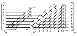
- FIG. 1 An example of an accumulator is shown in FIG. 1 for a specific A which applies to an 8-bit vector.
- FIG. 1 (as well as each of FIGS. 2 to 4 ) shows a slice for a single value of j, if the operations are interpreted single bit, or the entire accumulator block, if K identical operations are piled perpendicularly to the plane of the paper. For clarity, the descriptions below are given for a single j. In each of these figures, time and causality move left to right. The same or similar components in FIGS. 1-4 are given the same or similar reference symbols.
- FIG. 1 shows an accumulator for the A defined in equation (23) above, or expressed as the 8-th degree primitive polynomial 101110001 (constant term to left).
- the accumulator has an accumulator input 11 (trunk input), a side input 12 , and an accumulator output 13 (trunk output), where A (a) is the lowest and H (h) the highest order bit.
- the bits may be indexed by a width-wise coordinate i.
- Splitters 14 allow some inputs to drive more than one output.
- Each of XOR combiners 15 and 17 combines two inputs to generate one output bit.
- a shift 16 is interposed before combiner 17 (the side combiner), and shifts each bit except H to the next higher bit position, while H is shifted to A.
- a latching mechanism ensures that each bit of the trunk input 11 and side input 12 is stable in time to drive all dependent bits of the output 13 . This allows for many kinds of sequencing and tradeoffs between time and area, including parallel, pipelined or serial operations using standard, wide-XOR, or specialized hardware.
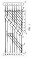
- FIG. 2 shows an accumulator for the matrix A 2 (see equation (26)), acting upon accumulator input 11 and side input 12 to give accumulator output 13 .
- First splitters 14 a, first combiners 15 a and first shift 16 a are identical to splitters 14 , combiners 15 and shift 16 in FIG. 1 , respectively.
- Second splitters 14 b, second combiners 15 b and second shift 16 b are also structurally identical to splitters 14 , combiners 15 and shift 16 , respectively, but operating on bits that have been operated on by the first splitters 14 a, first combiners 15 a and first shift 16 a, creating a net effect of a repeated application of the matrix A.
- Side combiner 17 has the same effect as side combiner 17 in FIG. 1 .
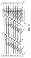
- FIG. 3 shows an accumulator equivalent to that of FIG. 2 , but with a reduced total number of combiners, at the cost of a ninth temporary storage bit 18 .
- Splitters 14 c and combiners 15 c create nine storage bits, splitter 14 d and combiners 15 d reduce these to eight again.
- Shift 16 c in FIG. 3 shifts each of bits A to F by two bits, and shifts bits G and H to A and B, respectively.
- the eight bits after shift 16 c are equivalent to the eight bits in FIG. 2 after shift 16 b.
- the side combiners 17 have the same effect as the side combiners 17 in FIG. 2 , producing an identical result as FIG. 2 .
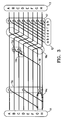
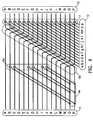
- FIG. 4 shows an accumulator for a matrix B 2 , where B is defined from the 16th degree polynomial 10010001001000001 in the same way the matrix A was defined from the polynomial 101110001. Because of the character of the matrix B, it is possible to postpone the two-bit shift 16 d till after splitters 14 e and combiners 15 e in such a way that all combines 15 e can be performed in one step in the pipeline. This plus side combiners 17 finishes the accumulate in two pipeline steps, even though B is squared, in contrast to the three pipeline steps required for A 2 in either FIG. 2 or FIG. 3 .
- the collection of splits 14 , XOR combiners 15 and shifts 16 located before the side combiner 17 can be considered to form a mapping pattern (logic) that maps the accumulator input 11 to a pattern-mapped vector which is subsequently combined with the side input 12 .
- the Horner's accumulator described above may be implemented either in hardware or in software.
- the splitters and shifts may be implemented by conductors and do not require a separate pipeline step.
- a single accumulator circuit can perform all the multiply accumulates for the calculation of q from the b's. This provides high efficiencies in hardware implementations.
- identical copies of the accumulator circuit may be used sequentially such that the trunk output of one accumulator is fed to the trunk input of the next accumulator. This also requires different data blocks b i to be fed into different copies of the accumulator.
- the above two approaches may be combined; for example, multiple copies of the accumulator circuit are connected sequentially and the trunk output of the last accumulator is coupled to the trunk input of the first accumulator, or the operation is iterated on one accumulator and then its output coupled to the input of another accumulator.
- Decoding involves calculating the syndromes corresponding to missing data disks and valid parity disks, and applying an inverse of a square submatrix of the encoding matrix to the syndromes.
- the syndromes may be efficiently calculated by the Horner's methods described earlier. As the count of data erasures k increases, the relative cost of multiplying k syndromes by the inverse of a k by k matrix whose entries are finite field elements may come to dominate decoding costs, especially for smaller d.
- Embodiments of the present invention include methods for efficient decoding of the Reed-Solomon-like codes. Two methods are described: One uses a tower coordinate technique to efficiently carry out finite field element calculations for large N; the other uses a stored one-dimensional table of powers of ⁇ and Schur expressions to efficiently calculate the inverse of the square submatrices of the encoding matrix.
- a code based on 32-bit finite field is used as an example in efficiency calculations, but it will be apparent to those skilled in the art that a similar analysis can be carried out for any bit field of dimension a power of 2, such as 16, 64, etc.
- a finite field technique has been known for extending each finite field of dimension a power of 2 to the finite field of dimension the next power of 2, and using this tower of extensions to permit finite field addition by bitwise XORing, and finite field multiplication and inversion in the bigger field through combinations of similar operations in the smaller field.
- a bit vector of the smaller field FS is called a “short”
- a bit vector of the larger field FL called a “long”
- ninvS nmulS nsquS ncmuS nxorS ( 10000 33000 10200 11130 34112 ) ⁇ ( ninvL nmulL nsquL ncmuL nxorL ) ( 32 ) where ninvS and ninvL are the number of inversions in FS and FL, respectively; nmulS and nmulL are the number of multiplies in FS and FL, respectively; nsquS and nsqulL are the number of squarings in FS and FL, respectively; ncmuS and ncmuL are the number of constant-multiplies in FS and FL, respectively; and nxorS and nxorL are the number of multiplies in FS and FL, respectively.
- Q 1 since in the bit field, parallel multiplication is AND and parallel extended inverse is the identity or no-op.
- the general algorithm may be implemented in hardware or software. Described in more general terms, what is disclosed is a technique of performing operations, including multiplication and, independently, constant multiplication by a certain fixed constant, as well as further useful capabilities such as inversion, on input digital signals that represent elements of a first finite field of dimension 2*N (e.g. the larger field FL in the above example) to produce output signals that represent results of the operations. For each such input digital signal, two intermediate signals are formed, each representing an element of a second finite field of dimension N (e.g. the smaller field FS in the above example).
- N e.g. the larger field FL in the above example
- a first input signal in the first field is expressed as yx
- the input signals may include a second input signal vu, and the two corresponding intermediate signals v and u are related to vu by the field element A.
- operations are performed using these intermediate signals to generate additional intermediate signals, and operations may be performed using these additional intermediate signals, where the operations include at least a constant multiply, i.e. multiply of a field element by the fixed element g.
- the operations must also include general multiplies (multiplies of two arbitrary field elements) and general adds, and may include inversion or squaring.
- the method used for constant multiply which is by A*g in the field of dimension 2*N and by g in the field of dimension N, is independent of the method used for the general multiply for the field of dimension 2*N and may be independent for the field of dimension N.
- output signals are formed, each representing an element of the first field (the larger field FL) that is the result an operation on one or more field elements represented by the input signals, which may be inversion, multiply, squaring, constant multiply (by the element A*g in the first field), or addition.
- addition in the larger field requires only addition in the smaller field
- constant multiply requires only constant multiply and addition
- general multiply requires only general multiply, constant multiply, and addition.
- general multiply of size 2*N requires only three general multiplies of size N
- constant multiply of size 2*N requires only three constant multiplies of size N. From this, the better than N squared efficiency follows for all operations including inversion.
- the input signals, intermediate signals and output signals can be in any form, including signals existing in a processor being acted upon by the processor according to program instructions, and signals existing in hard wired logic being acted upon by the logic elements.
- the description is general also in that the input signals may be the result of some upstream processing and the output signals may be subject to further downstream processing, and the nature of either processing is unimportant for purposes of the methods described here.
- This technique may be applied repeatedly to further extend the dimension of the field, such as to extend from the field of dimension 2*N to the field of dimension 4*N.
- the functions are nested, including the appropriate constant multiplies. For example, a 32-bit element may be written as (highest order byte on left)
- an inverse of a square submatrix of the encoding matrix (the inverse may be referred to as the decoding matrix) is applied to the syndromes corresponding to missing data disks and valid parity disks.
- the syndromes may be efficiently calculated using Horner's method described earlier.
- standard matrix multiplication software or hardware can generate the required decoded data using long XORs or other efficient techniques.
- Gaussian elimination For calculating matrix inverses, a well-known technique is Gaussian elimination, where for instance row operations are applied to
- the present embodiment describes an efficient method of calculating matrix inverse. Every square submatrix of the Reed-Solomon-like encoding matrix defined earlier in this disclosure (equation (3)) can be written in the form “e>f> . . . ” where e,f, . . . are an increasing sequence of integers between s and s+m ⁇ 1, and “e>f> . . .
- V M
- the Schur expression is always a symmetric polynomial in ⁇ i , ⁇ j . . . .
- #i+j:i+k:j+k is a notation of the polynomial, with exponents of ⁇ separated by colons.
- the inverse matrix is the transpose of the matrix of minors, generated by removing the indexed row and column, divided by the (scalar) determinant of the original matrix.
- the sign can be ignored because this is characteristic 2.
- JI ⁇ e > f > ... ⁇ ⁇ ... ⁇ ⁇ ⁇ ( i , j , ... ⁇ ⁇ ... ⁇ ) ⁇ e > f > ... ⁇ ⁇ ⁇ ( i , j , ... ⁇ ) ( 38 ) where the (i, j, . . .
- both the numerator and denominator on the right of (38) are the product of a Schur expression and a shifted Vandermonde determinant, which in turn is the product of a shift term of form
- Step 1 Generate the Schur expression for S0f′ . . . corresponding to e>f> . . . ; in this case, S01234; as this will be shared by all Q I for columns of minors. In this case this is 1 and Step 1 can be omitted.
- Step 3 Generate the inverse of Q I , by multiplying with the output of Step 1 if necessary, and inverting. In this case the multiply is not needed, and the inversion costs effort of 30.
- Step 4 Generate the row of inverse matrix entries by calculating the required Schur expression for each minor and multiplying it, if necessary, by the output of Step 3.
- the first minor is ⁇ 1>0>1>2> and its Schur expression is S1234 which is #i+j+k+1. This calculation requires three integer operations, one lookup, and one multiply, for effort of 33.
- the second minor is ⁇ 2>0>1>2> and its Schur expression is S0234 which (see Appendix) is #i+j+k:i+j+l:i+k+l:j+k+l, and the calculation requires eight integer operations, four lookups, three XORs, and one multiply, for effort of 44.
- the total effort per inverse row of Steps 2 through 4 is 236. Therefore the effort for the entire inverse calculation, including Step 1, is 1180, which is less than one third the effort using Gaussian elimination (3710, see Table 4). Note that the effort in both Table 4 and here are by using the tower coordinate technique.
- the efficient method of calculating the matrix inverse includes pre-storing a one-dimensional table of powers of ⁇ , calculating the matrix inverse using Cramer's rule, expressing the minors using Schur expressions, and calculating the Schur expression by performing table lookup in the table of powers of a and other necessary field element operations.
- the field element operations involved in the matrix inverse calculation may be performed directly in the original (powers of ⁇ ) coordinates, where the powers of a are stored as bit vectors; or performed by using the tower coordinate extension technique described earlier. These different coordinates may be referred to as different mappings of the field to N-bit vectors.
- the mapping which is efficient for the encoding method and syndrome calculation is not necessarily efficient for arbitrary field element multiplication and especially inversion, when the field is too large for full tabulation.
- a second mapping such as tower coordinates, which is mathematically equivalent to the standard mapping and related to it by an N ⁇ N bit matrix multiplication and its inverse, may be desirable for the calculation of decoding matrices.
- the field elements are expressed in the tower coordinates, and the one-dimensional table of powers of a and other tables needed for efficient multiplication and inversion are stored in the tower coordinates.
- the tables may be stored in a nested fashion down to basic “shorts” of 8 bits, with 16-bit tables as described.
- a bit linear (matrix) transformation is applied to change the field element from the tower coordinates to their vector expressions in the larger field (i.e. the vector expressions used in encoding).
- this transformation requires two lookups and one XOR per decoding matrix entry, thus 75 total operations for a 5 ⁇ 5 decoding matrix.
- the decoding matrix entries (which are field elements) are further converted from vector expressions to matrix expressions. This requires, for the 32-bit field example, multiplying by the first 31 natural number powers of ⁇ . For a 5 ⁇ 5 decoding matrix, there are 25 elements that need to be converted. This can be done efficiently using the Horner approach described earlier, by indexing the field elements with the depth-wise coordinate j in the Horner's accumulator. The Horner's accumulator used for this calculation may omit the side input and side combiner (see FIG. 1 ).
- a parallel one-dimensional table of powers of ⁇ in the original (powers of ⁇ ) coordinates may be stored to efficiently handle the special case where the square submatrix of the encoding matrix is 1 ⁇ 1.
- Such a case i.e. only one data disk is missing
- the 1 ⁇ 1 decoding matrix can be obtained by direct table lookup using this table.
- Such a table may be stored in either bit vector or bit matrix form. If stored in a matrix form (which is preferable), the table can also be used to convert the field element from the vector expression to the matrix expression mentioned in the preceding paragraph.
- multiplying the syndrome data by the square decoding matrix is efficiently performed by reordering the bits of the decoding matrix into a number of bit fields treated as unsigned integers.
- Each integer corresponds to an XOR accumulate of a subset of a set of syndrome data fields onto a subset of the decoded data.
- the matrix multiply is performed by looping over all of the integers.
- K corresponding bits of such output are generated by XORing the results of 4k operations, each a 256-branch choice leading to an XOR sum of from 0 to 8 K-wide input bit data sets.
Abstract
Description
- 1. Field of the Invention
- This invention relates to method and apparatus for providing a multiply redundant RAID system.
- 2. Description of the Related Art
- RAID (Redundant Array of Independent Disks) is a data storage system that employs two or more disk drives (or storage devices in general) and delivers fault tolerance and performance. RAID architectures that can tolerate multiple disk failures (i.e. multiply redundant) are known. One such system is described in Wiencko et al., “Data Redundancy Methods and Apparatus”, U.S. Pat. No. 6,557,123, filed 2 Aug. 1999, issued 29 Apr. 2003, assigned to the assignee of the present disclosure, which describes a method for encoding data that protects against simultaneous m disk failures in an array of n disks, as well as a code discovery method. Other methods for double- or triple-disk failure protection are also known; one category of such methods uses Reed-Solomon or Reed-Solomon-like codes.
- Reed-Solomon (R-S) error correction is a coding scheme which works by first constructing a polynomial from the data symbols to be transmitted and then sending an over-sampled plot of the polynomial instead of the original symbols. (See Wikipedia: “Reed-Solomon error correction”, http://en.wikipedia.org/wiki/Reed-Solomon_error_correction.) Thus, a matrix for a massively over-sampling R-S on two symbols (matrix on the right notation and linear polynomials) would be
where α, β, γ, . . . χ are n distinct values in some finite field. If α is primitive and a generator of the multiplicative group, and the number of coded values (matrix columns) is less than the order of the field, then one may have
β=α2
γ=α3
and so forth: this leads to straightforward algorithms (Berlekamp) for solving for errors. The coding of (1) is called “non-systematic” because nowhere among the entries to code((x y)) do x or y themselves necessarily appear. To get a systematic code, one for which the data appears in clear form among the coded values, one may multiply the matrix on the left by a 2×2 matrix that forces the left two columns to an identity matrix. But then, there is no simple expression for the matrix entries. - The above example has only two data points and n−2 parities. To increase the data dimension, add rows raising α, β, γ, . . . to consecutive powers, and use Vandermonde. Realistic cases will sample n times in a polynomial of degree n−m−1, where m is comparatively small (perhaps 2 or 3) and n large (perhaps 15 or larger). This makes the solution expression more complicated, if a systematic code is desired.
- A variant, which only needs to be mentioned here, is that found in Murthy et al., “Multiple Drive Failure Recovery for a Computer System having an Array of Storage Drives”, U.S. Pat. No. 6,694,479. This uses a matrix like that found in (1), but as an implicit condition, requiring multiplication with a data/parity vector on the right of the matrix to give zero. For this variant, the data dimension would be n−2 and the parity dimension 2. It is easily extended (by Vandermonde) to parity greater than 2 by adding rows raising α, β, γ, . . . to consecutive powers. This amounts to a “dual” form of standard Reed-Solomon.
- Another algorithm has also been called “Reed-Solomon” (in Blaum et al., “EVENODD: An Optimal Scheme for Tolerating Double Disk Failures in RAID Architectures”, IEEE, 1994, pp 245-254, 1063-6897/94, hereinafter [B2]), or “B-adjacent” (in Blaum et al., “Method and Means for B-Adjacent Coding and Rebuilding Data from up to Two Unavailable DASDs in a DASD Array”, U.S. Pat. No. 5,333,143, hereinafter [B1]). It places the matrix like that found in (1) below an identity matrix and uses it to multiply by a data vector on the right, expressed as equation (2) below. This automatically gets a systematic code if it works. But Vandermonde, by itself, does not prove it works.
Here I is an identity matrix, and the parity matrix P has horizontal dimension equal to the vector to be encoded, and vertical dimension equal to the parity count (dimension of code vector minus dimension of vector that was encoded). - The requirement for a non-systematic expression of the form of (1) to give an erasure code, where any surviving set of code values of the count of the data values can be decoded, is for all square submatrices of maximal size of the matrix in (1) to be invertible. This is obvious in the case of equation (1) because they are Vandermonde.
- The requirement for a systematic expression of the form of (2) to give an erasure code, where any surviving set of code values of the count of the data values can be decoded, is for all square submatrices of the parity matrix P to be invertible. This does not follow in general if maximal submatrices are Vandermonde.
- However, if P in (2) is set equal to the row dimension 2 matrix in (1), and we require that α, β, . . . be unequal and nonzero, then the stronger requirement that all square submatrices be invertible is satisfied. Namely, one just needs to prove it for 1×1 square submatrices, which are invertible if nonzero. This is the approach used in [B1] to obtain a redundancy 2 code. This Reed-Solomon-based method has sometimes been referred to as “RAID6”. It is also the code used in [B2] as a foil to Evenodd, and in [B2] it is called “Reed-Solomon”. In the present disclosure it is referred to as “Reed-Solomon-like”.
- The present invention is directed to a coding method apparatus that substantially obviates one or more of the problems due to limitations and disadvantages of the related art.
- An object of this invention is to provide an efficient, high-redundancy erasure code and data encoding method usable for general arrays, including very large arrays.
- Additional features and advantages of the invention will be set forth in the descriptions that follow and in part will be apparent from the description, or may be learned by practice of the invention. The objectives and other advantages of the invention will be realized and attained by the structure particularly pointed out in the written description and claims thereof as well as the appended drawings.
- An improved and extended Reed-Solomon-like method for providing a redundancy of m≧3 is described. A general expression of the codes is described (see equations (2a), (3)), as well as a systematic criterion for proving correctness and finding decoding algorithms for values of m greater than 2. Examples of codes are given for m=3, 4, 5, based on primitive elements of a finite field FN of dimension N over the field of two elements (also known as the “bit field”) where N is 8, 16 or 32. In addition, a method is described using a base power s of the primitive element α to further increase calculation efficiency.
- A Horner's method and accumulator apparatus are described for XOR-efficient evaluation of polynomials with variable vector coefficients and constant sparse square matrix abscissa. This method is easily used for large dimensions, allowing, in particular, for low gate count and low XOR count operations on large finite fields. It is particularly suitable for application to parity generation for Reed-Solomon-like multiple redundancy RAID algorithms.
- XOR-efficient decoding methods are also described. One decoding method uses a tower coordinate technique to efficiently carry out finite field element calculations for large N. Another decoding method uses a stored one-dimensional table of powers of α and Schur expressions to efficiently calculate the inverse of the square submatrices of the encoding matrix. These two methods may be used in conjunction with each other.
- It is to be understood that both the foregoing general description and the following detailed description are exemplary and explanatory and are intended to provide further explanation of the invention as claimed.
-
FIGS. 1-4 illustrate Horner's accumulators according to embodiments of the present invention. - Embodiments of this invention provide an efficient, high-redundancy erasure code and data encoding method usable for general disk arrays, including very large arrays. In this disclosure, “disk” should be generally understood to mean any suitable storage devices. Several conditions are desirable for an efficient algorithm: The algorithms should preferably be (a) space-optimal, (b) seek-optimal and (c) stripe-size-minimal for a given value of n (total disks) and m (redundancy, or the maximum number of disks that may simultaneously fail without any loss of user data). Condition (a) means that they must encode n−m disks worth of virtual data, recovering all the data from any n−m surviving disks. Condition (b) means that each data entry must affect parity on exactly m other disks (the Singleton bound). Condition (c) means that each data/parity stripe must intersect each disk in exactly one chunk. Here the bit size of a “chunk” is preferably a power of 2. A “data/parity stripe” is the minimum self-contained unit of data and parity that (from an encoding and decoding point of view) is completely independent of all other data and parity. Here, “self-contained” is normally taken to include a requirement for computational efficiency, so that for example the stripe and indeed the chunk may consist of a number of physical or logical disk sectors.
- By contrast, the Evenodd scheme described in [B2] and Blaum et al., “Method and Means for Encoding and Rebuilding the Data Contents of up to Two Unavailable DASDs in a DASD Array using Simple Non-Recursive Diagonal and Row Parity”, U.S. Pat. No. 5,579,475, and the codes described in U.S. Pat. No. 6,557,123 (“the Wiencko codes”) are space-optimal. Wiencko codes are sometimes seek-optimal and sometimes not, and Evenodd is not seek-optimal. Both Wiencko codes and Evenodd are very far from being stripe-size-minimal. The stripe size intersection for Wiencko code disks is n/gcd(n,m) chunks, and the stripe size intersection for Evenodd is p−1 chunks where p is a prime greater than or equal to n−2. (gcd(n,m) is the greatest common divisor of n and m.) These are general formulas; they sometimes may have factors of a power of 2 which, by redefinition of a chunk, can reduce the intersection chunk count.
- Another condition desirable for an efficient algorithm is that (d) valid algorithms should be easily found even for large n and m. This is a given for Reed-Solomon, and any Vandermonde-based code, and works for Evenodd—for m=2 only—because there is a general formula based on the next prime p. Wiencko codes are found by searches which become more difficult as n and m increase, if one requires small-dimension finite field expressions.
- Another desirable condition, which is not easily satisfied by Reed-Solomon variants, is: (e) The number of XORs required to encode parity should not be much in excess of the theoretical minimum, which is m*(n−m−1) XORs per n−m bits of data. This minimum follows from the Singleton bound since each of the n−m data entries must appear in m parities. Wiencko codes equal or come near to this optimum in many cases, and Evenodd is close, especially for large n. But standard Reed-Solomon misses it by a large factor, due to the complexity of finite field operations, and according to [B2] the Reed-Solomon-like m=2 code even follows a higher power law. Known Wiencko codes also miss the optimum by a large factor when n and m become large.
- New methods are needed for m=2 and 3 that satisfy condition (c) and (e) simultaneously for large n. New methods are especially needed for m>3, to satisfy all these requirements at once. Embodiments of the present invention provide such methods. Embodiments of the invention also teach a systematic criterion for proving correctness (and finding decoding algorithms) for values of m greater than 3. Other embodiments of the present invention teach a pipeline method to vastly improve XOR efficiency, so that large finite field size becomes an advantage.
- Specific embodiments of the present invention are now described. In the following descriptions, finite fields of Characteristic 2 (bit) fields are used as an example, but the methods can be extended to other finite fields.
- Encoding Algorithm, Conditions for Correct Codes and Code Examples
- In the present disclosure, the meanings of various common mathematical symbols are easily understood from their context. For instance, “+” between vectors or matrices is addition over the bit field (or other fields if appropriate), while “+” in the exponents is integer addition. When special notations are used, they are expressly defined. It is assumed that one of ordinary skill in the relevant art has general knowledge of finite field theory.
- A first embodiment of the present invention is a method of constructing a multiple-redundancy erasure code and a data encoding method using such a code. According to this embodiment, a code (referred to as Reed-Solomon-like code) for coding data symbols b0, b1, . . . bd−1 (where d is the data dimension) has the form
where I is an identity matrix and P is a parity matrix, which is defined as follows:
where α is a primitive element of a finite field FN, typically taken to be a generator of the multiplicative group. Here d is the data dimension, m is the parity (redundancy) count, s is an integer base power (the significance of which will be explained later), the step (in the second column) for the power going down is 1, and the power increases linearly from left to right in every row. The code generated by equation (2a) thus contains d+m symbols, including d data symbols and m parity symbols calculated from the parity matrix P. - Note that the formula for the parity calculation employed by the Reed-Solomon-like B-adjacent parity in [B1] and [B2], which is given by setting the parity matrix in equation (2a) above as
is a special case of (3) for s=0 and m=2. (Note that the data dimension is labeled m in [B2].) It has also been suggested that the Reed-Solomon-like method for m=2 could be extended to m=3, which would be a special case of (3) for s=0, m=3. See F. J. MacWilliams and N. J. A. Sloane, “The Theory of Error-Correcting Codes,” Amsterdam, The Netherlands: North-Holland, 1977, page 326, and Mario Blaum, Jim Brady, Jehoshua Bruck, Jai Menon, and Alexander Vardy: “The EVENODD Code and its Generalization: An Efficient Scheme for Tolerating Multiple Disk Failures in RAID Architectures”,Chapter 14, “High Performance Mass Storage and Parallel {I/O}: Technologies and Applications”, Hai Jin and Toni Cortes and Rajkumar Buyya, editors, IEEE Computer Society Press and Wiley, 2001. - In embodiments of the present invention, the finite field FN is of dimension N over the bit field. Each symbol bi is N-bit and is mapped onto the field FN by a mapping. The field FN is generated as an algebra over the bit field by the primitive element α satisfying an irreducible polynomial equation
p(α)=0
where
p(x)=x N +c N−1 x N−1 + . . . +c 1 x+1 (5)
where the c's are 0 or 1, addition is over the bit field (that is, it is bitwise XOR), and multiplication is in the field FN. This can be expressed by expressing α as an N×N matrix over the bit field:
Then, as is known from algebra and finite field theory, an isomorphic image of the entire field FN is spanned by powers of this matrix, which may be thought of as operating on the right of row vectors of coefficients of powers of α, with the leftmost entry in the vector being the constant coefficient. In preferred embodiments, N is a power of 2, so as to satisfy condition (c) above. - Now define
αk=αs+k (7)
The k-th parity symbol calculated from the parity matrix (3) is (counting k from 0) - This expression can be efficiently evaluated using Horner's method, which in field notation gives:
q k =b 0+αk(b 1+αk(b 2+ . . . αk(bd−1) . . . )) (8a)
Horner's method may be implemented by a Horner's accumulator described later, with one species of accumulator for the matrix expression of each αk. As will be seen, a Horner's method accumulator achieves XOR-efficient evaluation of polynomials with variable vector coefficients and constant sparse square matrix abscissa. - The parity matrix P set forth in equation (3) will give a correct Reed-Solomon-like code if all square submatrices of P are nonsingular (referred to here as the “strong invertibility condition”). As used in the instant disclosure, a submatrix is a matrix consisting of the intersection of a number of rows and a number of columns of the original matrix. This strong invertibility condition is not always satisfied. Methods for finding efficient and correct Reed-Solomon-like code for redundancy m greater than 2 will now be described.
- First of all, assume α is nonzero and hence invertible. It follows that any value of s in the parity matrix (3) is equivalent from the point of view of correctness, since changing s amounts to multiplying each column by a nonzero constant, which does not affect matrix invertibility. The analysis to follow, therefore, will treat the case s=0 and the powers therefore run from 0 to m−1, as in a standard Vandermonde type matrix. Each row of P will be labeled by its index k counting from 0, which is therefore also its row power. The strong invertibility condition is reduced to: For every integer M between 1 and min(m,d) inclusive, and every ordered subset of M−1 integers {i2, . . . iM} between 1 and d−1, and every ordered subset of M−1 integers {j2, . . . jM} between 1 and m−1, the determinant of the matrix
is nonzero in the field FN (i.e. the matrix is nonsingular). - Based on the strong invertibility condition, the conditions for giving correct Reed-Solomon-like codes for m up to 5 will be enumerated. Based on these descriptions, those skilled in the art will understand how to extend this method for m greater than 5.
- m=1 always works (i.e. gives a correct code), and is known as RAID4. m=2, as mentioned above, works if α is nonzero and all the powers of α in the second row are different. This is equivalent to the requirement that the order of α in the multiplicative group of FN be greater than or equal to d. By choosing α to be a primitive element that is a generator of the multiplicative group, this is equivalent to the requirement
d<2N (10)
For N=8, the requirement is d<256. The above code finding methods for m=1 and m=2 are known in the art. - In what follows, a square submatrix of P is defined to be of form “i>j> . . . ” if its rows are subsets of rows i, j, . . . . Thus the number of rows is equal to the count of entries in the form expression. The term “Vandermonde” is used to mean “Vandermonde with differing columns”, and therefore Vandermonde will imply invertible. Multiplying each column of a matrix by a nonzero scalar will be referred to as “column scaling”, and multiplying each row of a matrix by a nonzero scalar will be referred to as “row scaling”. If the matrix is square, neither row scaling nor column scaling affects its invertibility. Both “+” and “−” are used to mean characteristic 2 addition (bitwise XORing). The notation M followed by numbers indicates the rows are raised to those powers times i for the first column, j for the second column, k for the third column (if any), etc. The notation L followed by numbers indicates the rows are raised to those powers multiplied by 0 for the first column, i times the second, etc.
- For the m=3 case, again, α is assumed to be nonzero of order greater than or equal to d. Then all square submatrices of size 1 work because they are nonzero scalars. All square submatrices of size 3 work because they are form “0>1>2>” which is Vandermonde. Of square submatrices of size 2, “0>1>” works because it is Vandermonde, and “1>2>” works because it is produced by multiplying each column of a Vandermonde matrix by a nonzero scalar.
- A matrix of form “0>2>” has the general form
where 0<=i<j<d. Its determinant is
|M02|=α2j−α2i=(αj−αi)2 =|M01|2 (12)
where the last equality holds because the field is of characteristic 2. Therefore, under the order assumption, |M02| is always nonzero. The case m=3 thus works for the same α and maximum d as the corresponding case m=2, with no further conditions required, as long as the field is of characteristic 2. Some examples of codes for m=3 are given in Table 1 below. - For the case m=4, under the same assumptions as imposed on m=2 and m=3, square submatrices of size 1 are invertible because they are nonzero, and square submatrices of size 4 are invertible because they are Vandermonde. The forms for size 2 are “0>1>”, “1>2>”, “2>3>” (all Vandermonde or column scaled Vandermonde), “0>2>”, “1>3>” (all invertible by the argument of (12) or column scaled from such a matrix), and “0>3>”. The general form for the last case is
where 0<=i<j<d. Its determinant is
|M03|=α3j−α3i=(α2i+αi+j+α2j)|M01| (14)
which is nonzero if and only if 3(j−i) is not a multiple of the order of α. This will always be satisfied if
(IVa)d<=order(α)/gcd(order(α),3) - To continue the m=4 case, the forms for size 3 are “0>1>2”, “1>2>3>” (all Vandermonde or column scaled Vandermonde), “0>1>3” and “0>2>3>”. The general form for “0>1>3>” is, for 0<=i<j<k<d:
Row scaling implies that invertibility of (15) is equivalent to invertibility of the specialization where the left power is 0: for 0<i<j<d,
A similar general form for “0>2>3>” can be reduced to (16) by reversing the order of rows, reversing the order of columns, column scaling, and row scaling. - By analogy, the “0>1>2>” Vandermonde specialization may be defined as
then direct evaluation of the determinant shows that
|L013|=(1+αi+αj)|L012| (18)
and so M013 is invertible if and only if (characteristic 2)
(IVb)αi+αj≠1 for all i and j such that 0<i<j<d
For any d and nonzero α such that the conditions (IVa) and (IVb) hold, the m=4 version of (3) is a correct Reed-Solomon-like code. Some examples of correct codes for m=4 are given in Table 1 below. - For the case m=5, all the conditions required for m=4 must hold for the same α and the same d, since the set of square submatrices of the version of P for m=4 is a subset of the set of square submatrices of the version of P for m=5. In fact it equals the set of square submatrices that do not have 4> in their form. As before, size 1 and size maximum (5) hold because of nonzero entries and Vandermonde respectively. Size 2 has the following forms including 4>: “0>4>”, “1>4>”, “2>4>”, and “3>4>”. Of these, the last three are column scalings of “0>3>”, “1>3>”, and “2>3>”, which are already known to work by the conditions for m=4. That leaves “0>4>”, which is proved Vandermonde by the same argument as “0>2>” was in (11) and (12), since this is a field of characteristic 2.
|M04|=α4j−α4i =|M01|4 =|M02|2 (12b) - Size 3 has the following forms including 4>: “0>1>4>”, “0>2>4>”, “0>3>4>”, “1>2>4>”, “1>3>4>, “2>3×4>”. Of these, the last three are column scalings of “0>1>3>”, “0>2>3>”, and “1>2>3>” respectively, and thus known to work by the conditions for m=4. “0>2>4>” is Vandermonde, since its columns are squared from the columns of “0>1>2>” and, since this is a field of characteristic 2, are thus unequal if the latter are. “0>3>4>” is equivalent to “0>1>4>” by the technique used on “0>2>3>” above. This leaves (after reduction as from (15) to (16))
then direct evaluation of the determinant shows that
|L014|=(1+αi+αj+α2i+αi+j+α2j)|L012| (20)
which is nonzero if and only if (characteristic 2)
(Va) αi+αj+α2i+αi+j+α2j≠1 for all i and j such that 0<i<j<d - Size 4 has the following forms including 4>: “0>1>2>4”, “0>1>3>4”, “0>2>3>4”, and “1>2>3>4>”. Of these, “1>2>3>4>” is column shifted from “0>1>2>3>” and so valid, and “0>2>3>4>” is equivalent to “0>1>2>4>” by an argument analogous to that used for “0>2>3>”. Direct evaluation, using notation analogous to the above (with 4×4 matrices for 0<i<j<k<d) gives for “0>1>2>4>”
|L0124|=(1+αi+αj+αk)|L0123| (21)
leading to the requirement
(Vb) αi+αj+αk≠1 for all i, j, k such that 0<i<j<k<d
And, for “0>1>3>4>” it gives
|L0134|=(αi+αj+αk+αi+j+αi+k+αj+k)|L0123| (22)
which is nonzero if and only if
(Vc) αi+αj+αk+αi+j+αi+k+αj+k≠0 for all i, j, k such that 0<i<j<k<d
For any d and nonzero α such that the conditions (IVa), (IVb), (Va), (Vb), and (Vc) hold, the m=5 version of (3) is a correct Reed-Solomon-like code. Some examples of correct codes for m=5 are given in Table 1 below. - Based on the above descriptions, those skilled in the art can extend this technique to any m>5, and also to any field, since equations relating any form determinant to the corresponding Vandermonde determinant can be derived using symmetric polynomial theory.
- Finding irreducible polynomials and primitive elements for any N is a well-known exercise in field theory. The number of irreducible polynomials of degree N over the bit field is approximately
2N/N
(the exact formula involves Moebius functions) and so increases rapidly with N. Since for any fixed value of d and m, the set of conditions of the kind of IVa, IVb required to prove (3) works comprise a fixed, finite set of polynomials required to be simultaneously nonzero, they can have only a limited number of points of failure. Thus, for N big enough, a value of a is guaranteed to exist for which (3) satisfies the strong invertibility condition for this m and d. - The value of N required to guarantee this by the analysis is high, especially if one requires the polynomials to be sparse. Therefore a search among sparse irreducible polynomials is desirable, testing all the conditions for various m to find valid d. This is a modest exercise in computer programming, which tends to uphold the far more optimistic view that the condition failure locations (roots) behave as if random. Some specific results are given below. The polynomials in this table are expressed as a string of their coefficients in the form 1C1C2 . . . CN−11 (see equation (5)). (Taking the coefficients in the opposite order is equally valid in every case, since it provides the minimal polynomial for α−1.) The “XOR excess” column will be described later.
TABLE 1 N m d maximum XOR excess Polynomial 8 3 255 6/24 = 25% 101110001 16 3 >255 6/48 = 13% 10010001001000001 32 3 >255 6/96 = 7% # 8 4 33 11/32 = 35% 110100011 16 4 >255 12/64 = 19% 10010001001000001 32 4 >255 11/128 = 9% # 8 5 13 16/40 = 40% 110110001 16 5 102 18/80 = 23% 10010001001000001 16 5 120 30/80 = 37% 10010001101000101 32 5 >255 16/160 = 10% # 32 5 >255 18/160 = 11% ##
# 100000000000000000011100000000001
## 100000000000000010000001000000101
- All but one of the polynomial examples given in Table 1 have only three non-zero coefficients in addition to CN and C0. In other words, they satisfy an irreducible polynomial equation
αN+αh+αg+αf+1=0
where f, g and h are integers satisfying 0<f<g<h<N. - To summarize, embodiments of the present invention include the technique of using the conditions IVa, IVb, Va, Vb, and Vc and the technique for deriving further similar conditions and using them, for proving the strong invertibility condition is satisfied and thus equation (3) is a valid Reed-Solomon-like parity encoding matrix.
- XOR Efficiency and Horner's Method Accumulator
- Another embodiment of the present invention is the application of the Horner's method for computing polynomials involved in Reed-Solomon-like algorithms. As pointed out earlier, the k-th parity symbol calculation using the parity matrix P
can be efficiently evaluated using Horner's method with one species of accumulator for the matrix expression of each αk:
q k =b 0+αk(b 1+αk(b 2+ . . . αk(bd−1) . . . )) (8a)
using field notation. For αk=1, the accumulator would be a trivial accumulator. - Each step in the Horner method requires N+Mk XORs, where Mk is the number of XORs required for a multiply by αk matrix, and there are d−1 identical steps. The matrix α is sparse, and irreducible polynomial p can be chosen so that it is also sparse: for N=8, 16, and 32 there are desirable values of p in which only three of the coefficients ci are nonzero for 0<i<N (see Table 1 above for examples). In such a case, the matrix α has only N+3 nonzero entries. Let us use as an example the following primitive element α (N=8):
Multiplying an 8-bit vector by α=A requires three XORs. With k=1 and s=0, the Horner requirement in XOR count is
XOR count=(8+3)(d−1)=11(d−1) (24) - This is more efficient than the approach described in [B2]. There, the general formula for the equation (2a)-style parity calculation is, in respect of (2a), given by setting P as in equation (4). [B2] describes calculating the parity
by explicitly performing each multiplication (whereas [B1] describes pre-calculating the coefficients). For α=A as set forth above (see [B2] Equation (14)), explicitly performing each multiplication yields the total XOR count given by [B2] (page 251, left column): - Though the coefficient is small, the square term has discouraging results as d becomes very large. The XOR count using the Horner's method according to embodiments of the present invention is never worse than the quadratic value given in [B2], and rapidly becomes much better:
TABLE 2A d 1 2 3 4 10 20 Optimal 0 8 16 24 72 152 Horner(24) 0 11 22 33 99 209 [B2] (25) 0 11 25 42 207 722
XOR count for second parity, example in [B2]
- The first parity, in this case, is s=0, k=0, and the multiplication is skipped. Adding these XORs one gets:
TABLE 2B d 1 2 3 4 10 20 Optimal 0 16 32 48 144 304 Horner(24) 0 19 38 57 171 361 [B2] (25) 0 19 41 66 359 894
XOR count for complete parity, example in [B2]
Notice that the ratio between Horner and optimal remains constant, that is, in this (m=2) case (M1+2N)/(2N) assuming M0=0. (Here Mk is the numbers of XORs required for multiplication by the matrix version of αk=αs+k.) This gives 19/16 in this case. The ratio of excess XORs to the optimal is M1/(2N), which gives 3/16 or 19% in this case. - In Table 1 set forth earlier, the column labeled “XOR excess” summarizes the ratio of excess XORs for the code examples given therein (using the balanced strategy of setting the base power s, see below). It can be seen that the percent of XOR excess actually decreases as N increases. Because of the Horner accumulator, a large finite field can be used with little code size burden. This is an advantage of embodiments of the present invention not achieved by other Reed-Solomon-related methods. It makes the techniques described here highly desirable for encoding very large arrays, like d=255, m=5.
- In the parity matrix expression (3), the integer s can be set freely. This may be used to change the powers of α to further reduce the XOR count of the parity calculation. The typical best value for s is −[(m−1)/2] where [x] is the greatest integer less than or equal to x (i.e., s=−(m−1)/2 for odd m and s=−(m−2)/2 for even m). To illustrate this, consider the square of the matrix A given in equation (23):
Using a temporarily stored XOR of the rightmost two bits in the row vector being multiplied on the right by this matrix, one can reduce the number of XORs for a multiply to 5, but that is still greater than the 3 required for a multiply by A. Now, contrast the inverse of the matrix A:
Multiplication by this matrix, like multiplication by A, requires only three XORs. - Thus, the m=3 algorithm based on α=A is improved in efficiency by using s=−1 as opposed to s=0. Using the same consideration as in the discussion of Tables 2A and 2B above, one finds that for s=0 the ratio of excess XORs to the optimal is (0+3+5)/(8+8+8)= 8/24=33%, while for s=−1 this ratio is (3+0+3)/(8+8+8)= 6/24=25%. The optimal approach for sparse polynomials is to balance the powers, which is done by setting s=−[(m−1)/2], as mentioned above.
- To further increase the efficiency of the algorithm, consideration may also be given when choosing the primitive element α for a code. For example, if higher powers are required, as for m>3, it is desirable to keep the nonzero coefficients in α as far as possible from the ends; i.e. take care that c1, c2, . . . are zero and CN−1, CN−2, . . . are zero insofar as possible. If minimum XOR count is desired, for a specific degree of sparseness, then having all the nonzero coefficients together (as in A in equation (23)) is desirable for higher powers. If XORs can be done in parallel within a Horner step, then optimization is accomplished by separating the nonzero coefficients from one another. That results in at most two 1s in a column even for higher powers, meaning all XORs can be done in parallel. This is not practical for N=8, but works well for bigger N. Examples will be further discussed later in connection with the Horner accumulator. In the examples given in Table 1, the 32nd degree polynomial #100000000000000000011100000000001 is optimized for serial XORs. The 32nd degree polynomial ##100000000000000010000001000000101 satisfies the parallel optimization condition for powers between −2 and +2.
- Another embodiment of the present invention is a Horner's method accumulator apparatus and method developed for XOR-efficient evaluation of polynomials with variable vector coefficients and constant sparse square matrix abscissa, such as equation (8) above. This accumulator is easily used for very large dimensions, allowing, in particular, for low gate count and low XOR count operations on large finite fields such as 16 and 32 bit fields. It is particularly suitable for application to parity and syndrome generation for the Reed-Solomon-like multiple redundancy RAID algorithms described earlier. The Horner's accumulator operation on very large fields thus permits encoding algorithms with XOR count efficiency better than that offered by known methods based on finite fields limited in practice to 8 bits.
- In what follows, the Horner's accumulator is described as applying to a rectangular chunk (or block) of data of N by K bits, where N is the dimension of a finite field over the bit field {0,1} (i.e. the bit vector dimension) and K is a count of bit vectors. The implementation is identical for each bit vector, indexed by a depth-wise coordinate j ranging from 0 to K−1. For a fixed N×N bit matrix A, expressed as a fixed sequence of bit shifts and XORs, the same A for each incrementally accumulating vector variable accj and input side vector bj (both N-wide row vectors), the accumulator's operation may be expressed as
acc j=(acc j *A)+b j - An example of an accumulator is shown in
FIG. 1 for a specific A which applies to an 8-bit vector.FIG. 1 (as well as each of FIGS. 2 to 4) shows a slice for a single value of j, if the operations are interpreted single bit, or the entire accumulator block, if K identical operations are piled perpendicularly to the plane of the paper. For clarity, the descriptions below are given for a single j. In each of these figures, time and causality move left to right. The same or similar components inFIGS. 1-4 are given the same or similar reference symbols. -
FIG. 1 shows an accumulator for the A defined in equation (23) above, or expressed as the 8-th degree primitive polynomial 101110001 (constant term to left). The accumulator has an accumulator input 11 (trunk input), aside input 12, and an accumulator output 13 (trunk output), where A (a) is the lowest and H (h) the highest order bit. The bits may be indexed by a width-wise coordinate i.Splitters 14 allow some inputs to drive more than one output. Each ofXOR combiners shift 16 is interposed before combiner 17 (the side combiner), and shifts each bit except H to the next higher bit position, while H is shifted to A. - A latching mechanism (not shown in the drawing) ensures that each bit of the
trunk input 11 andside input 12 is stable in time to drive all dependent bits of theoutput 13. This allows for many kinds of sequencing and tradeoffs between time and area, including parallel, pipelined or serial operations using standard, wide-XOR, or specialized hardware. -
FIG. 2 shows an accumulator for the matrix A2 (see equation (26)), acting uponaccumulator input 11 andside input 12 to giveaccumulator output 13.First splitters 14 a,first combiners 15 a and first shift 16 a are identical tosplitters 14,combiners 15 andshift 16 inFIG. 1 , respectively.Second splitters 14 b,second combiners 15 b andsecond shift 16 b are also structurally identical tosplitters 14,combiners 15 andshift 16, respectively, but operating on bits that have been operated on by thefirst splitters 14 a,first combiners 15 a and first shift 16 a, creating a net effect of a repeated application of the matrixA. Side combiner 17 has the same effect asside combiner 17 inFIG. 1 . -
FIG. 3 shows an accumulator equivalent to that ofFIG. 2 , but with a reduced total number of combiners, at the cost of a ninthtemporary storage bit 18.Splitters 14 c andcombiners 15 c create nine storage bits,splitter 14 d andcombiners 15 d reduce these to eight again. Unlike theshifts 16 inFIG. 1 and 16 a, 16 b inFIG. 2 ,Shift 16 c inFIG. 3 shifts each of bits A to F by two bits, and shifts bits G and H to A and B, respectively. The eight bits aftershift 16 c are equivalent to the eight bits inFIG. 2 aftershift 16 b. Then theside combiners 17 have the same effect as theside combiners 17 inFIG. 2 , producing an identical result asFIG. 2 . -
FIG. 4 shows an accumulator for a matrix B2, where B is defined from the 16th degree polynomial 10010001001000001 in the same way the matrix A was defined from the polynomial 101110001. Because of the character of the matrix B, it is possible to postpone the two-bit shift 16 d till aftersplitters 14 e andcombiners 15 e in such a way that all combines 15 e can be performed in one step in the pipeline. Thisplus side combiners 17 finishes the accumulate in two pipeline steps, even though B is squared, in contrast to the three pipeline steps required for A2 in eitherFIG. 2 orFIG. 3 . - In each of
FIGS. 1-4 , the collection ofsplits 14,XOR combiners 15 and shifts 16 located before theside combiner 17 can be considered to form a mapping pattern (logic) that maps theaccumulator input 11 to a pattern-mapped vector which is subsequently combined with theside input 12. - The accumulators described above are merely examples, and Horner's accumulators for other primitive elements (such as those shown in Table 1) as well as other positive and negative powers of the primitive elements can be similarly constructed.
- The Horner's accumulator described above may be implemented either in hardware or in software. In a hardware implementation, the splitters and shifts may be implemented by conductors and do not require a separate pipeline step.
- Although the descriptions above deal with single bit operations, large efficiencies can be gained by doing bulk operations for j ranging over K values for a large K. This bulk effect can be achieved, for example, with multiple hardware copies of an accumulator fitting the design described, or with one or more accumulators each operating a wide-XOR engine at every XOR combine point, or with software using wide efficient XOR commands at every XOR combine point, or with combinations of the above. Such replication is aided, for a given gate count, by the fixed nature of the matrix multiplication pattern for each constant matrix.
- To compute the polynomial q discussed earlier,
a full block output q is generated from d input blocks bi by the following pipeline of d−1 accumulator steps (here for clarity j is omitted, though the preferred embodiment of the invention uses j ranging over large K):
All d−1 steps involve an add and a multiplication by the same matrix A. For example, if the value of A is hardcoded with shifts and XORs, a single accumulator circuit can perform all the multiply accumulates for the calculation of q from the b's. This provides high efficiencies in hardware implementations. Alternatively, identical copies of the accumulator circuit may be used sequentially such that the trunk output of one accumulator is fed to the trunk input of the next accumulator. This also requires different data blocks bi to be fed into different copies of the accumulator. Alternatively, the above two approaches may be combined; for example, multiple copies of the accumulator circuit are connected sequentially and the trunk output of the last accumulator is coupled to the trunk input of the first accumulator, or the operation is iterated on one accumulator and then its output coupled to the input of another accumulator. - The Horner accumulator described above allows efficient processing of large sized data blocks, such as N*K>32. This provides an advantage over other methods of implementing parity and syndrome calculations which tend to be limited to the 32-bit size of the processors used. Thus, the Horner accumulator improves the efficiency even in the redundancy m=2 (RAID6) or m=3 case, since known methods have practically been limited to the N=8 field. In addition, known methods for parity and syndrome calculation are practically limited by word-wide multipliers, handling for example four 8-bit field elements at a time for a 32-bit word, while the Horner accumulator described here can use wide XOR techniques to transcend word limit even for N>8.
- Efficient Decoding Methods
- In a RAID system encoded with the encoding algorithm described above, when up to m data and/or parity blocks are lost, the lost data and/or parity can be reconstructed by a decoding algorithm to solve the erasure patterns. Decoding involves calculating the syndromes corresponding to missing data disks and valid parity disks, and applying an inverse of a square submatrix of the encoding matrix to the syndromes. The syndromes may be efficiently calculated by the Horner's methods described earlier. As the count of data erasures k increases, the relative cost of multiplying k syndromes by the inverse of a k by k matrix whose entries are finite field elements may come to dominate decoding costs, especially for smaller d.
- Embodiments of the present invention include methods for efficient decoding of the Reed-Solomon-like codes. Two methods are described: One uses a tower coordinate technique to efficiently carry out finite field element calculations for large N; the other uses a stored one-dimensional table of powers of α and Schur expressions to efficiently calculate the inverse of the square submatrices of the encoding matrix.
- An efficient method for calculating finite field element products and inverses is described first. A code based on 32-bit finite field is used as an example in efficiency calculations, but it will be apparent to those skilled in the art that a similar analysis can be carried out for any bit field of dimension a power of 2, such as 16, 64, etc. A finite field technique has been known for extending each finite field of dimension a power of 2 to the finite field of dimension the next power of 2, and using this tower of extensions to permit finite field addition by bitwise XORing, and finite field multiplication and inversion in the bigger field through combinations of similar operations in the smaller field. A description of this method in the context of efficient software operations can be found in Aoki and Ohta: “Fast Arithmetic Operations over F2n for Software Implementation”, hereinafter [AO], found in SAC'97 “Presented Papers”, at www.scs.carleton.ca/˜sac97/program/FinalPapers/paper24.ps. Different from the techniques described in [AO] reference, however, the present embodiment treats constant multiply by certain constants specified herein as a separate category of operation than multiply. This provides further efficiencies not achieved by the [AO] method.
- According to the tower coordinate extension technique, if a bit vector of the smaller field FS is called a “short”, then a bit vector of the larger field FL, called a “long”, is built of two “shorts”, one high order and one low, with the usual little-endian 0-based numbering. A fixed element g of FS can be found such that the equation
X 2 +X+g=0 (28)
does not have a solution in FS. The extension technique expresses any element of FL as yx (y to the left of x, or y the high order “short” and x the low order “short”) where A in FL is selected to satisfy (28), i.e.,
A 2 +A+g=0 (29)
and
yx=(y*A)+x (30)
It follows that if vu is similarly (v*A)+u, then addition works trivially by bitwise XOR in FL if it worked by bitwise XOR in FS, and by (29) one gets
yx*vu=((y*v)+(y*u)+(x*v))*A+((x*u)+(y*v*g)) (31)
This can be programmed as
q=(y+x)*(v+u)
r=x*u;
s=r+(y*(v*g));
t=q+r;
and then yx*vu=ts. Thus, three multiplies, one constant-multiply (by g), and four XORs in FS give one multiply in FL. - Similarly, note that if v=y and u=x+y in the above calculation, then t comes out 0, and s (which is in FS) is nonzero unless both x and y are 0. Thus, for nonzero yx, one can get ts equal the inverse of yx by the program
q=y*((y*g)+x)+square(x);
r=inverse(q);
s=r*(x+y)
t=r*y
So, an inversion in FL requires one inversion, three multiplies, one squaring, one constant-multiply, and three XORs in FS. - Similar considerations show that one squaring in FL requires two squarings, one constant multiply, and one XOR in FS; and one XOR in FL requires two XORs in FS. Note that both squaring and constant multiply are given special categories because they can be tabulated for a bigger field (i.e. 16 bit) than multiply (which can be tabulated only for an 8-bit field, unless one has 8GB of table memory available).
- Finally, as noted in [AO], A*g in FL serves the same purpose as g in FS, since X2+X+A*g=0 has no solution in FL under the assumptions on g and A; so the special constant multiply in FL is yx*g0=(y*A+x)*(g*A)=t*A+s where t=(y+x)*g and s=y*g*g. Therefore, a constant-multiply in FL requires three constant-multiplies and one XOR in FS.
- The matrix for doubling the field bit count is:
where ninvS and ninvL are the number of inversions in FS and FL, respectively; nmulS and nmulL are the number of multiplies in FS and FL, respectively; nsquS and nsqulL are the number of squarings in FS and FL, respectively; ncmuS and ncmuL are the number of constant-multiplies in FS and FL, respectively; and nxorS and nxorL are the number of multiplies in FS and FL, respectively. - An easy analysis shows it has eigenvalues of 1, 2, and 3, meaning both the multiply and the inversion are efficient. As pointed out earlier, the present embodiment differs from the [AO] reference in that constant multiply by the g specified in equation (28) is treated as a separate category, with the result being an efficiency matrix with all eigenvalues less than 4, as seen in equation (32). If through use of table lookups, one assumes that 16-bit inversion, 8-bit multiply, 16-bit squaring, 16-bit constant multiply, and 32-bit XORing are elementary (unit effort) operations, then 32-bit effort is as follows:
TABLE 3 32-bit operation effort inversion 30 multiply 29 squaring 4 constant-multiply 4 XOR 1 - The efficient finite field element calculation method described above is useful in other applications as well, such as cryptography. It is also generally useful in any application in which two large sets of elements of a finite field of applicable dimension are multiplied or divided pointwise, i.e. c[i]=b[i]*a[i] or c[i]=b[i]/a[i]. Here “applicable dimension” means
N=2k *Q
where Q is small enough so that efficient methods are known for multiplying or extended-inverting field elements of dimension Q in parallel, where the extended inverse of an element is its inverse if the element is nonzero but 0 if the element is 0. In particular, it includes the case where Q=1, since in the bit field, parallel multiplication is AND and parallel extended inverse is the identity or no-op. - The general algorithm may be implemented in hardware or software. Described in more general terms, what is disclosed is a technique of performing operations, including multiplication and, independently, constant multiplication by a certain fixed constant, as well as further useful capabilities such as inversion, on input digital signals that represent elements of a first finite field of dimension 2*N (e.g. the larger field FL in the above example) to produce output signals that represent results of the operations. For each such input digital signal, two intermediate signals are formed, each representing an element of a second finite field of dimension N (e.g. the smaller field FS in the above example). The two intermediate signals and the input signal are related by an element A of the first finite field, where A satisfies the equation
A 2 +A+g=0 (29)
where g is a fixed (constant) element of the second finite field such that the equation
X 2 +X+g=0 (28)
does not have a solution X in the second finite field. In the example above, a first input signal in the first field is expressed as yx, and the two corresponding intermediate signals are y and x, where the relationship between the input signal yx and the intermediate signals y and x is
yx=(y*A)+x. (30)
Similarly, the input signals may include a second input signal vu, and the two corresponding intermediate signals v and u are related to vu by the field element A. Then, operations are performed using these intermediate signals to generate additional intermediate signals, and operations may be performed using these additional intermediate signals, where the operations include at least a constant multiply, i.e. multiply of a field element by the fixed element g. The operations must also include general multiplies (multiplies of two arbitrary field elements) and general adds, and may include inversion or squaring. The method used for constant multiply, which is by A*g in the field of dimension 2*N and by g in the field of dimension N, is independent of the method used for the general multiply for the field of dimension 2*N and may be independent for the field of dimension N. - Then, using the intermediate signals so generated, output signals are formed, each representing an element of the first field (the larger field FL) that is the result an operation on one or more field elements represented by the input signals, which may be inversion, multiply, squaring, constant multiply (by the element A*g in the first field), or addition. Note that addition in the larger field requires only addition in the smaller field, constant multiply requires only constant multiply and addition, and general multiply requires only general multiply, constant multiply, and addition. In addition, general multiply of size 2*N requires only three general multiplies of size N, and constant multiply of size 2*N requires only three constant multiplies of size N. From this, the better than N squared efficiency follows for all operations including inversion.
- The above description is general in that the input signals, intermediate signals and output signals can be in any form, including signals existing in a processor being acted upon by the processor according to program instructions, and signals existing in hard wired logic being acted upon by the logic elements. The description is general also in that the input signals may be the result of some upstream processing and the output signals may be subject to further downstream processing, and the nature of either processing is unimportant for purposes of the methods described here.
- This technique may be applied repeatedly to further extend the dimension of the field, such as to extend from the field of dimension 2*N to the field of dimension 4*N. To do this, the functions are nested, including the appropriate constant multiplies. For example, a 32-bit element may be written as (highest order byte on left)
- vuyx
where v, u, y, and x are bytes (from a 8-bit field) and the actual number represented is
(vA+u)B+(yA+x)
where A (in the 16-bit field) and B (in the 32-bit field) satisfy
A 2 +A+g=0
B 2 +B+h=0
where g is in the 8-bit field and
h=A*g
according to the tower rules. - The method for efficient calculation of the inverse of the square submatrices of the encoding matrix is described next. As mentioned earlier, during decoding, an inverse of a square submatrix of the encoding matrix (the inverse may be referred to as the decoding matrix) is applied to the syndromes corresponding to missing data disks and valid parity disks. The syndromes may be efficiently calculated using Horner's method described earlier. Once the decoding matrix is calculated, standard matrix multiplication software or hardware can generate the required decoded data using long XORs or other efficient techniques. As to the calculation of the inverse of the square submatrix, it is often not practical to pre-store the inverses in a table (at least for larger matrix dimension and disk count).
- For calculating matrix inverses, a well-known technique is Gaussian elimination, where for instance row operations are applied to
- [B|I]
(B the square submatrix, I the identity matrix) to first reach - [U|L]
(U an upper triangular matrix with unit diagonal, L a lower triangular matrix), and then - [I|C]
- (I the identity, C the inverse of B). If the matrix to be inverted is of dimension M, and tests, substitutions and row swaps are considered to be effortless, then one inversion using this standard Gaussian elimination technique requires
TABLE 4 matrix dimension (M) 2 3 4 5 M scalar inversions 2 3 4 5 M(M − 1) (M + 1) multiplies 6 24 60 120 M(M − 1) (M − 1) XORs 2 12 36 80 effort (32 bit) 236 798 1896 3710
The last row of Table 4 gives an example for a 32 bit field, where the amounts of efforts are calculated using the tower coordinate extension technique and considerations previously described (see Table 3). The finite field element calculation may also be done in the 32-bit field directly without using the tower extension technique, which may give different amounts of efforts. - The present embodiment describes an efficient method of calculating matrix inverse. Every square submatrix of the Reed-Solomon-like encoding matrix defined earlier in this disclosure (equation (3)) can be written in the form “e>f> . . . ” where e,f, . . . are an increasing sequence of integers between s and s+m−1, and “e>f> . . . ” denotes a square matrix of form
for an increasing sequence i, j, . . . between 0 and d−1. Here m is the redundancy, d is the data disk count, and s is an integer normally selected so that 2s+m−1 approximately equals 0 (balance). (Note that in the encoder section earlier, matrices in the form of (33) were denoted by M followed by numbers.) - In what follows, i, j, . . . are treated as known and quasi-constant. The “M-th Vandermonde value” VM is defines as
V M=|0>1> . . . M−1>| (34)
and, for any size-M square matrix with e=0, the “Schur expression” S0f . . . is defines to be
S0f . . . =|0>f> . . . |/V M (35)
(Note that this is not standard notation for the Schur functions.) One will see that the Schur expression is always a symmetric polynomial in αi, αj . . . . For example,
S023=αi+j+αi+k+αj+k =#i+j:i+k:j+k (36)
where #i+j:i+k:j+k is a notation of the polynomial, with exponents of α separated by colons. Note here that in the polynomial expression “+” in the exponents is integer addition, while “+” between terms is XOR. All Schur expressions are symmetric polynomials in the i, j, k . . . powers of α. The following are some nontrivial Schur expressions (from standard Vandermonde 0>1>, 0>1>2>, 0>1>2>3 as the case may be) for Characteristic 2:
0>2>#i:j
0>3>#2i:i+j:2j
0>4>#3i:2i+j:i+2j:3j
0>1>3>#i:j:k
0>1>4>#2i:2j:2k:i+j:i+k:j+k
0>2>3>#i+j:i+k:j+k
0>2>4>#2i+j:2j+k:2k+i:2i+k:2j+i:2k+j
0>1>2>4>#i:j:k:l
0>1>3>4>#i+j:i+k:i+l:j+k:j+l:k+l
0>2>3>4>#i+j+k:i+j+l:i+k+l:j+k+l
Expanded, the formula for 0>2>3> above (as an example) means:
|0>2>3>|=(αi+j+αi+k+αj+k)|0>1>2| - In Schur expressions, to shift up (or down) by 1, add (or subtract) i+j+ . . . to (from) all exponents, thus:
−1>2>#i−j:0:j−i
0>3>#2i:i+j:2j
1>4>#3i+j:2i+2j:i+3j
They still need to be multiplied by their respective (Vandermonde) bases. Another way is to shift the Vandermonde bases (replace 0>1> with −1>0> for instance) and then use the standard Schur functions. In other words, note that in equation (35) a shift of the ef . . . terms both above and below by the same number leads to the same quotient. Thus, for example,
This is because shifting all the ef . . . terms by +1 amounts to multiplying the determinant by - αi+j+ . . .
which is nonzero and cancels top and bottom. - Due to the general expression (33), a pre-stored one-dimensional table of powers of a from −L1d to +L2d for small integers L1 and L2 (of the order of m) will suffice to allow inversion of (33), using Cramer's rule, for far lower cost than other known methods. For m=5, if shifting is used, the calculation of powers of α can be turned into lookups from tables of powers of α from −3 to +3 times the maximum exponent (i.e. d−1). If shifting is not used, the lookup tables have to go from −6 to +6 times this number.
- According to Cramer's rule, the inverse matrix is the transpose of the matrix of minors, generated by removing the indexed row and column, divided by the (scalar) determinant of the original matrix. The sign can be ignored because this is characteristic 2. Thus, one gets
where the (i, j, . . . ) are here made explicit so that one of them can be omitted (ˆ) and also one of the ef . . . is omitted. But, both the numerator and denominator on the right of (38) are the product of a Schur expression and a shifted Vandermonde determinant, which in turn is the product of a shift term of form - αei+ei+ . . .
and a number of binomials of form (characteristic 2) - (αi+αj)
For the complexities of interest, the Schur expressions are short, and the Vandermonde factors tend to cancel. A single row of the inverse has the same subset of the ij . . . and can therefore be generated by Schur expressions multiplied through by the same expression, the inverse of
(where the I-th i, j, . . . value is omitted by ˆ and f′=f−e, etc.) in which the entire denominator cancels, meaning the rational function QI is a polynomial. This and other approaches can be used to reduce the number of multiplications and inversions at minimal cost in lookups and index calculations for the one-dimensional table. - Described below is an illustrative example for the inverse of −2>−1>0>1>2>, the only case that arises with M=5 if m=5 and s is balanced (s=−2). Again, the amount of efforts is calculated using the tower coordinate extension technique described earlier (see Table 3); if finite field element calculation is done without using the tower extension technique, the effort figures may be different.
- (Step 1) Generate the Schur expression for S0f′ . . . corresponding to e>f> . . . ; in this case, S01234; as this will be shared by all QI for columns of minors. In this case this is 1 and Step 1 can be omitted.
- All following steps are repeated for each column of minors. The indices in the case described below will be appropriate for the last column, the one corresponding to m. In the following description of Step 2, “m” means the 5th base power of α, not the redundancy. Note that e=−2.
- (Step 2) Generate the expression
Q I /S0f′ . . . =α eiI V M /V M−1(i, j, . ˆ . . ) (40)
In this case it is - If one assumes that integer operations of sign change, subtraction and addition and one-dimensional table lookup are each unit effort, then the evaluation of (41) using the strategy on the bottom consists of four integer operations, eight table lookups, six XORs, and one multiply, with total effort of 47. Integer operations and table lookups are treated (like XORs) as having an effort of 1.
- (Step 3) Generate the inverse of QI, by multiplying with the output of Step 1 if necessary, and inverting. In this case the multiply is not needed, and the inversion costs effort of 30.
- (Step 4) Generate the row of inverse matrix entries by calculating the required Schur expression for each minor and multiplying it, if necessary, by the output of Step 3.
- (a) The first minor is −1>0>1>2> and its Schur expression is S1234 which is #i+j+k+1. This calculation requires three integer operations, one lookup, and one multiply, for effort of 33.
- (b) The second minor is −2>0>1>2> and its Schur expression is S0234 which (see Appendix) is #i+j+k:i+j+l:i+k+l:j+k+l, and the calculation requires eight integer operations, four lookups, three XORs, and one multiply, for effort of 44.
- (c) The third minor is −>−1>1>2>, the Schur expression is S0134=#i+j:i+k:i+l:j+k:j+l:k+l for effort of 46.
- (d) The fourth minor is −2>−1>0>2, Schur expression S0124=#i:j:k:l, and effort is 36.
- (e) The fifth minor is −2>−1>0>1>, Schur expression S0123=1, and effort is 0.
- The total effort per inverse row of Steps 2 through 4 is 236. Therefore the effort for the entire inverse calculation, including Step 1, is 1180, which is less than one third the effort using Gaussian elimination (3710, see Table 4). Note that the effort in both Table 4 and here are by using the tower coordinate technique.
- To summarize, the efficient method of calculating the matrix inverse (the decoding matrix) includes pre-storing a one-dimensional table of powers of α, calculating the matrix inverse using Cramer's rule, expressing the minors using Schur expressions, and calculating the Schur expression by performing table lookup in the table of powers of a and other necessary field element operations.
- The field element operations involved in the matrix inverse calculation may be performed directly in the original (powers of α) coordinates, where the powers of a are stored as bit vectors; or performed by using the tower coordinate extension technique described earlier. These different coordinates may be referred to as different mappings of the field to N-bit vectors. The mapping which is efficient for the encoding method and syndrome calculation is not necessarily efficient for arbitrary field element multiplication and especially inversion, when the field is too large for full tabulation. Thus a second mapping, such as tower coordinates, which is mathematically equivalent to the standard mapping and related to it by an N×N bit matrix multiplication and its inverse, may be desirable for the calculation of decoding matrices.
- If the tower coordinate technique is used, the field elements are expressed in the tower coordinates, and the one-dimensional table of powers of a and other tables needed for efficient multiplication and inversion are stored in the tower coordinates. In the 32-bit field example, the tables may be stored in a nested fashion down to basic “shorts” of 8 bits, with 16-bit tables as described. After the decoding matrix is calculated (using the tower coordinates), a bit linear (matrix) transformation is applied to change the field element from the tower coordinates to their vector expressions in the larger field (i.e. the vector expressions used in encoding). In the 32-bit field example, this transformation requires two lookups and one XOR per decoding matrix entry, thus 75 total operations for a 5×5 decoding matrix.
- To apply the decoding matrix to the syndromes, the decoding matrix entries (which are field elements) are further converted from vector expressions to matrix expressions. This requires, for the 32-bit field example, multiplying by the first 31 natural number powers of α. For a 5×5 decoding matrix, there are 25 elements that need to be converted. This can be done efficiently using the Horner approach described earlier, by indexing the field elements with the depth-wise coordinate j in the Horner's accumulator. The Horner's accumulator used for this calculation may omit the side input and side combiner (see
FIG. 1 ). The signal on the trunk output is either switchably connected to the corresponding bit of the trunk input via a latch or connected to the trunk input of another accumulator so as to generate a sequence of products of the initial trunk input by increasing powers of αs+k, which may be successively outputted at a side output connected to the trunk output. If the 25×32 bit array is transpose addressed during the Horner method operation, with the example of α value given in Table 1 (# or ##, having three nonzero coefficients), it would require 32×31×3=2976 XOR operations at least 25 bits deep. Greater relative gains are possible with wider XOR operations, if rotational symmetry is imposed by rotating the disk indices in the RAID algorithm (like RAID5), because this requires multiple syndrome decoding patterns, most of which will be of the same dimension if d is large. - If the tower coordinate technique is used, a parallel one-dimensional table of powers of α in the original (powers of α) coordinates may be stored to efficiently handle the special case where the square submatrix of the encoding matrix is 1×1. Such a case (i.e. only one data disk is missing) is expected to be relatively common. Since each entry in the parity matrix is a power of α, so is its inverse. Thus, the 1×1 decoding matrix can be obtained by direct table lookup using this table. Such a table may be stored in either bit vector or bit matrix form. If stored in a matrix form (which is preferable), the table can also be used to convert the field element from the vector expression to the matrix expression mentioned in the preceding paragraph.
- To use the decoding matrix (in bit matrix form under the powers of α mapping) to generate decoded data from syndrome data, multiplying the syndrome data by the square decoding matrix is efficiently performed by reordering the bits of the decoding matrix into a number of bit fields treated as unsigned integers. Each integer corresponds to an XOR accumulate of a subset of a set of syndrome data fields onto a subset of the decoded data. The matrix multiply is performed by looping over all of the integers. For N=32, for example, a single bit of decoded output is the dot-product of 32k bits of arbitrary syndrome input with k 32-bit columns of the fixed decoding matrix. Using K-wide XOR operations, K corresponding bits of such output are generated by XORing the results of 4k operations, each a 256-branch choice leading to an XOR sum of from 0 to 8 K-wide input bit data sets.
- The result for a single RAID4-like decode, in the M=5 example given above, will be 25 matrices or 3200 bytes, which can be looped through, with each (transpose addressed) byte branching one of 256 ways to cause between 0 and 8 wide XOR accumulates on syndrome data. Most real-world decodes are expected to be less burdensome, with disk replacement taking place while only three or fewer disks are down, even in very large arrays of hundreds of disks.
- It will be apparent to those skilled in the art that various modification and variations can be made in the method and apparatus of the present invention without departing from the spirit or scope of the invention. For example, the encoding and decoding methods may be implemented in hardwired logic or in software/firmware, or combinations thereof. Some implementations can be accomplished by those skilled in the relevant art based on the description in this disclosure. Thus, it is intended that the present invention cover modifications and variations that come within the scope of the appended claims and their equivalents. In particular, the claims written in the “means” language are intended to broadly encompass any suitable hardware or software structures that implement the functions and their equivalents.
Claims (39)
αN+αh+αg+αf+1=0
α8+α7+α3+α1+1=0.
α16+α10+α7+α3+1=0
α32+α21+α20+α19+1=0.
α8′a4+α3+α1+1=0.
α16+α10+α7+α3+1=0.
α16+α14+α10+α8+α7+α3+1=0.
α32+α21+α20+α19+1=0.
α32+α30+α23+α16+1=0.
p b(x)=b 0 +x(b 1 +x(b 2 + . . . x(b d−1) . . . ))
acc=(acc*x)+b i.
A 2 +A+g=0
X2 +X+g=0
Priority Applications (3)
| Application Number | Priority Date | Filing Date | Title |
|---|---|---|---|
| US11/080,093 US7219289B2 (en) | 2005-03-15 | 2005-03-15 | Multiply redundant raid system and XOR-efficient method and apparatus for implementing the same |
| PCT/US2006/009446 WO2006099517A2 (en) | 2005-03-15 | 2006-03-15 | Multiply redundant raid system and xor-efficient implementation |
| EP06738498A EP1859452A4 (en) | 2005-03-15 | 2006-03-15 | Multiply redundant raid system and xor-efficient implementation |
Applications Claiming Priority (1)
| Application Number | Priority Date | Filing Date | Title |
|---|---|---|---|
| US11/080,093 US7219289B2 (en) | 2005-03-15 | 2005-03-15 | Multiply redundant raid system and XOR-efficient method and apparatus for implementing the same |
Publications (2)
| Publication Number | Publication Date |
|---|---|
| US20060218470A1 true US20060218470A1 (en) | 2006-09-28 |
| US7219289B2 US7219289B2 (en) | 2007-05-15 |
Family
ID=36992426
Family Applications (1)
| Application Number | Title | Priority Date | Filing Date |
|---|---|---|---|
| US11/080,093 Expired - Fee Related US7219289B2 (en) | 2005-03-15 | 2005-03-15 | Multiply redundant raid system and XOR-efficient method and apparatus for implementing the same |
Country Status (3)
| Country | Link |
|---|---|
| US (1) | US7219289B2 (en) |
| EP (1) | EP1859452A4 (en) |
| WO (1) | WO2006099517A2 (en) |
Cited By (25)
| Publication number | Priority date | Publication date | Assignee | Title |
|---|---|---|---|---|
| US20090044075A1 (en) * | 2005-12-08 | 2009-02-12 | Christopher Jensen Read | Failure tolerant data storage |
| US20090055705A1 (en) * | 2006-02-08 | 2009-02-26 | Wen Gao | Decoding of Raptor Codes |
| US20090132851A1 (en) * | 2007-11-21 | 2009-05-21 | Arvind Pruthi | Parallel reed-solomon raid (rs-raid) architecture, device, and method |
| US20090164762A1 (en) * | 2007-12-20 | 2009-06-25 | Microsoft Corporation | Optimizing xor-based codes |
| US20110214011A1 (en) * | 2010-02-27 | 2011-09-01 | Cleversafe, Inc. | Storing raid data as encoded data slices in a dispersed storage network |
| US8037391B1 (en) * | 2009-05-22 | 2011-10-11 | Nvidia Corporation | Raid-6 computation system and method |
| US8296515B1 (en) | 2009-05-22 | 2012-10-23 | Nvidia Corporation | RAID-6 computation system and method |
| US20130151921A1 (en) * | 2011-12-13 | 2013-06-13 | Hironori Uchikawa | Encoding apparatus, encoding method and semiconductor memory system |
| US20140195574A1 (en) * | 2012-08-16 | 2014-07-10 | Empire Technology Development Llc | Storing encoded data files on multiple file servers |
| US20140351632A1 (en) * | 2010-02-27 | 2014-11-27 | Cleversafe, Inc. | Storing data in multiple formats including a dispersed storage format |
| US20150154072A1 (en) * | 2013-12-02 | 2015-06-04 | Annapurna Labs Ltd. | Flexible redundant array of independent disks (raid) computation device |
| US20160087802A1 (en) * | 2014-09-23 | 2016-03-24 | Texas Instruments Incorporated | Homogeneous Atomic Pattern for Double, Add, and Subtract Operations for Digital Authentication Using Elliptic Curve Cryptography |
| WO2016105727A1 (en) * | 2014-12-23 | 2016-06-30 | Intel Corporation | Apparatus and method for vector broadcast and xorand logical instruction |
| US9985661B1 (en) * | 2016-04-12 | 2018-05-29 | Xilinx, Inc. | Reed-Solomon erasure code decoder |
| US10073940B1 (en) * | 2016-09-27 | 2018-09-11 | Altera Corporation | Move based XOR optimization |
| US10097207B2 (en) * | 2016-03-10 | 2018-10-09 | Toshiba Memory Corporation | ECC circuit, storage device and memory system |
| US10116334B1 (en) * | 2016-12-12 | 2018-10-30 | Xilinx, Inc. | Reed-solomon code encoder and decoder |
| US10198319B1 (en) * | 2014-12-15 | 2019-02-05 | Amazon Technologies Inc. | Computation refinement storage in a data storage system |
| US10198317B1 (en) * | 2014-11-17 | 2019-02-05 | Amazon Technologies Inc. | Computation refinement in a data storage system |
| US10411736B2 (en) * | 2013-06-14 | 2019-09-10 | Samsung Electronics Co., Ltd. | Method and apparatus for encoding and decoding of low density parity check codes |
| WO2020029423A1 (en) * | 2018-08-09 | 2020-02-13 | 东莞理工学院 | Construction method and repair method for repairing binary array code check matrix |
| US20210160003A1 (en) * | 2011-08-25 | 2021-05-27 | Texas Instruments Incorporated | Networking Coding System in a Network Layer |
| CN113297001A (en) * | 2021-05-20 | 2021-08-24 | 山东云海国创云计算装备产业创新中心有限公司 | RAID (redundant array of independent disks) coding and decoding method and coding and decoding circuit |
| US11249846B2 (en) * | 2019-06-24 | 2022-02-15 | Huawei Technologies Co., Ltd. | Erasure code-based data processing method and apparatus |
| US11442809B1 (en) * | 2019-07-17 | 2022-09-13 | Marvell Asia Pte, Ltd. | Double-parity raid enabling recovery of two failed data units |
Families Citing this family (47)
| Publication number | Priority date | Publication date | Assignee | Title |
|---|---|---|---|---|
| US6307487B1 (en) | 1998-09-23 | 2001-10-23 | Digital Fountain, Inc. | Information additive code generator and decoder for communication systems |
| US7068729B2 (en) | 2001-12-21 | 2006-06-27 | Digital Fountain, Inc. | Multi-stage code generator and decoder for communication systems |
| US9240810B2 (en) | 2002-06-11 | 2016-01-19 | Digital Fountain, Inc. | Systems and processes for decoding chain reaction codes through inactivation |
| CN100539439C (en) * | 2002-10-05 | 2009-09-09 | 数字方敦股份有限公司 | The system coding of chain reaction sign indicating number and decode system and method |
| KR101170629B1 (en) | 2003-10-06 | 2012-08-02 | 디지털 파운튼, 인크. | Error-correcting multi-stage code generator and decoder for communication systems having single transmitters or multiple transmitters |
| EP1589687A1 (en) * | 2004-04-23 | 2005-10-26 | France Telecom | Method for sending a signal in a multi-antenna system, corresponding signal and method for channel estimation |
| KR101205758B1 (en) | 2004-05-07 | 2012-12-03 | 디지털 파운튼, 인크. | File download and streaming system |
| US7555701B2 (en) * | 2004-11-04 | 2009-06-30 | Adaptec, Inc. | Method and system for recovering from multiple drive failures |
| TWI329866B (en) * | 2005-01-07 | 2010-09-01 | Promise Technology Inc | Data storage system |
| US7644335B2 (en) * | 2005-06-10 | 2010-01-05 | Qualcomm Incorporated | In-place transformations with applications to encoding and decoding various classes of codes |
| US7577866B1 (en) * | 2005-06-27 | 2009-08-18 | Emc Corporation | Techniques for fault tolerant data storage |
| TWI361348B (en) * | 2005-09-02 | 2012-04-01 | Infortrend Technology Inc | Parity engine for use in storage virtualization controller and methods of generating data by parity engine |
| TWI309364B (en) * | 2005-09-02 | 2009-05-01 | Infortrend Technology Inc | Method and controller for processing data multiplication in raid system |
| CN101686107B (en) | 2006-02-13 | 2014-08-13 | 数字方敦股份有限公司 | Streaming and buffering using variable FEC overhead and protection periods |
| US9270414B2 (en) | 2006-02-21 | 2016-02-23 | Digital Fountain, Inc. | Multiple-field based code generator and decoder for communications systems |
| US8364891B2 (en) * | 2006-04-04 | 2013-01-29 | Permabit Technology Corporation | Storage assignment technique for scalable and fault tolerant storage system |
| US7971129B2 (en) | 2006-05-10 | 2011-06-28 | Digital Fountain, Inc. | Code generator and decoder for communications systems operating using hybrid codes to allow for multiple efficient users of the communications systems |
| US9386064B2 (en) | 2006-06-09 | 2016-07-05 | Qualcomm Incorporated | Enhanced block-request streaming using URL templates and construction rules |
| US9209934B2 (en) | 2006-06-09 | 2015-12-08 | Qualcomm Incorporated | Enhanced block-request streaming using cooperative parallel HTTP and forward error correction |
| US9432433B2 (en) | 2006-06-09 | 2016-08-30 | Qualcomm Incorporated | Enhanced block-request streaming system using signaling or block creation |
| US9178535B2 (en) | 2006-06-09 | 2015-11-03 | Digital Fountain, Inc. | Dynamic stream interleaving and sub-stream based delivery |
| US9419749B2 (en) | 2009-08-19 | 2016-08-16 | Qualcomm Incorporated | Methods and apparatus employing FEC codes with permanent inactivation of symbols for encoding and decoding processes |
| US9380096B2 (en) | 2006-06-09 | 2016-06-28 | Qualcomm Incorporated | Enhanced block-request streaming system for handling low-latency streaming |
| US7797612B2 (en) * | 2006-12-29 | 2010-09-14 | Intel Corporation | Storage accelerator |
| US7930611B2 (en) * | 2007-03-09 | 2011-04-19 | Microsoft Corporation | Erasure-resilient codes having multiple protection groups |
| US7904782B2 (en) * | 2007-03-09 | 2011-03-08 | Microsoft Corporation | Multiple protection group codes having maximally recoverable property |
| KR101129260B1 (en) * | 2007-09-12 | 2012-03-27 | 디지털 파운튼, 인크. | Generating and communicating source identification information to enable reliable communications |
| US9281847B2 (en) | 2009-02-27 | 2016-03-08 | Qualcomm Incorporated | Mobile reception of digital video broadcasting—terrestrial services |
| US8392654B2 (en) * | 2009-04-17 | 2013-03-05 | Lsi Corporation | Raid level migration for spanned arrays |
| US9288010B2 (en) | 2009-08-19 | 2016-03-15 | Qualcomm Incorporated | Universal file delivery methods for providing unequal error protection and bundled file delivery services |
| US9047217B2 (en) * | 2009-08-27 | 2015-06-02 | Cleversafe, Inc. | Nested distributed storage unit and applications thereof |
| US9917874B2 (en) | 2009-09-22 | 2018-03-13 | Qualcomm Incorporated | Enhanced block-request streaming using block partitioning or request controls for improved client-side handling |
| US20110280311A1 (en) | 2010-05-13 | 2011-11-17 | Qualcomm Incorporated | One-stream coding for asymmetric stereo video |
| US9596447B2 (en) | 2010-07-21 | 2017-03-14 | Qualcomm Incorporated | Providing frame packing type information for video coding |
| US8806050B2 (en) | 2010-08-10 | 2014-08-12 | Qualcomm Incorporated | Manifest file updates for network streaming of coded multimedia data |
| US9270299B2 (en) | 2011-02-11 | 2016-02-23 | Qualcomm Incorporated | Encoding and decoding using elastic codes with flexible source block mapping |
| US8958375B2 (en) | 2011-02-11 | 2015-02-17 | Qualcomm Incorporated | Framing for an improved radio link protocol including FEC |
| US9253233B2 (en) | 2011-08-31 | 2016-02-02 | Qualcomm Incorporated | Switch signaling methods providing improved switching between representations for adaptive HTTP streaming |
| US9843844B2 (en) | 2011-10-05 | 2017-12-12 | Qualcomm Incorporated | Network streaming of media data |
| US8914706B2 (en) | 2011-12-30 | 2014-12-16 | Streamscale, Inc. | Using parity data for concurrent data authentication, correction, compression, and encryption |
| US8683296B2 (en) | 2011-12-30 | 2014-03-25 | Streamscale, Inc. | Accelerated erasure coding system and method |
| US9294226B2 (en) | 2012-03-26 | 2016-03-22 | Qualcomm Incorporated | Universal object delivery and template-based file delivery |
| EP2675069A1 (en) * | 2012-06-15 | 2013-12-18 | Alcatel Lucent | Method for encoding with GLDPC codes based on reed-solomon component codes |
| US9304859B2 (en) | 2012-12-29 | 2016-04-05 | Emc Corporation | Polar codes for efficient encoding and decoding in redundant disk arrays |
| US9594634B2 (en) * | 2014-06-02 | 2017-03-14 | Intel Corporation | Techniques to efficiently compute erasure codes having positive and negative coefficient exponents to permit data recovery from more than two failed storage units |
| US9923668B2 (en) * | 2015-08-21 | 2018-03-20 | Samsung Electronics Co., Ltd. | Coded modulation architecture using sparse regression codes |
| US10635909B2 (en) * | 2015-12-30 | 2020-04-28 | Texas Instruments Incorporated | Vehicle control with efficient iterative triangulation |
Citations (12)
| Publication number | Priority date | Publication date | Assignee | Title |
|---|---|---|---|---|
| US4142174A (en) * | 1977-08-15 | 1979-02-27 | International Business Machines Corporation | High speed decoding of Reed-Solomon codes |
| US4763332A (en) * | 1987-03-02 | 1988-08-09 | Data Systems Technology Corp. | Shared circuitry for the encoding and syndrome generation functions of a Reed-Solomon code |
| US4782490A (en) * | 1987-03-16 | 1988-11-01 | Cythera Corporation | Method and a system for multiple error detection and correction |
| US5285455A (en) * | 1992-02-03 | 1994-02-08 | Lsi Logic Corporation | Serial data encoder |
| US5333143A (en) * | 1991-08-29 | 1994-07-26 | International Business Machines Corporation | Method and means for b-adjacent coding and rebuilding data from up to two unavailable DASDS in a DASD array |
| US5473620A (en) * | 1993-09-21 | 1995-12-05 | Cirrus Logic, Inc. | Programmable redundancy/syndrome generator |
| US5579475A (en) * | 1991-02-11 | 1996-11-26 | International Business Machines Corporation | Method and means for encoding and rebuilding the data contents of up to two unavailable DASDS in a DASD array using simple non-recursive diagonal and row parity |
| US6012159A (en) * | 1996-01-17 | 2000-01-04 | Kencast, Inc. | Method and system for error-free data transfer |
| US6557123B1 (en) * | 1999-08-02 | 2003-04-29 | Inostor Corporation | Data redundancy methods and apparatus |
| US6678855B1 (en) * | 1999-12-02 | 2004-01-13 | Microsoft Corporation | Selecting K in a data transmission carousel using (N,K) forward error correction |
| US6694479B1 (en) * | 2000-05-23 | 2004-02-17 | Hewlett-Packard Development Company, L.P. | Multiple drive failure recovery for a computer system having an array of storage drives |
| US20040117718A1 (en) * | 2002-12-16 | 2004-06-17 | Microsoft Corporation | Systems and methods for providing improved encoding and reconstruction of data |
Family Cites Families (1)
| Publication number | Priority date | Publication date | Assignee | Title |
|---|---|---|---|---|
| US6026420A (en) * | 1998-01-20 | 2000-02-15 | 3Com Corporation | High-speed evaluation of polynomials |
-
2005
- 2005-03-15 US US11/080,093 patent/US7219289B2/en not_active Expired - Fee Related
-
2006
- 2006-03-15 WO PCT/US2006/009446 patent/WO2006099517A2/en active Application Filing
- 2006-03-15 EP EP06738498A patent/EP1859452A4/en not_active Withdrawn
Patent Citations (12)
| Publication number | Priority date | Publication date | Assignee | Title |
|---|---|---|---|---|
| US4142174A (en) * | 1977-08-15 | 1979-02-27 | International Business Machines Corporation | High speed decoding of Reed-Solomon codes |
| US4763332A (en) * | 1987-03-02 | 1988-08-09 | Data Systems Technology Corp. | Shared circuitry for the encoding and syndrome generation functions of a Reed-Solomon code |
| US4782490A (en) * | 1987-03-16 | 1988-11-01 | Cythera Corporation | Method and a system for multiple error detection and correction |
| US5579475A (en) * | 1991-02-11 | 1996-11-26 | International Business Machines Corporation | Method and means for encoding and rebuilding the data contents of up to two unavailable DASDS in a DASD array using simple non-recursive diagonal and row parity |
| US5333143A (en) * | 1991-08-29 | 1994-07-26 | International Business Machines Corporation | Method and means for b-adjacent coding and rebuilding data from up to two unavailable DASDS in a DASD array |
| US5285455A (en) * | 1992-02-03 | 1994-02-08 | Lsi Logic Corporation | Serial data encoder |
| US5473620A (en) * | 1993-09-21 | 1995-12-05 | Cirrus Logic, Inc. | Programmable redundancy/syndrome generator |
| US6012159A (en) * | 1996-01-17 | 2000-01-04 | Kencast, Inc. | Method and system for error-free data transfer |
| US6557123B1 (en) * | 1999-08-02 | 2003-04-29 | Inostor Corporation | Data redundancy methods and apparatus |
| US6678855B1 (en) * | 1999-12-02 | 2004-01-13 | Microsoft Corporation | Selecting K in a data transmission carousel using (N,K) forward error correction |
| US6694479B1 (en) * | 2000-05-23 | 2004-02-17 | Hewlett-Packard Development Company, L.P. | Multiple drive failure recovery for a computer system having an array of storage drives |
| US20040117718A1 (en) * | 2002-12-16 | 2004-06-17 | Microsoft Corporation | Systems and methods for providing improved encoding and reconstruction of data |
Cited By (47)
| Publication number | Priority date | Publication date | Assignee | Title |
|---|---|---|---|---|
| US20090044075A1 (en) * | 2005-12-08 | 2009-02-12 | Christopher Jensen Read | Failure tolerant data storage |
| US20090055705A1 (en) * | 2006-02-08 | 2009-02-26 | Wen Gao | Decoding of Raptor Codes |
| US8239727B2 (en) * | 2006-02-08 | 2012-08-07 | Thomson Licensing | Decoding of raptor codes |
| US8645798B2 (en) | 2007-11-21 | 2014-02-04 | Marvell World Trade Ltd. | Parallel Reed-Solomon RAID (RS-RAID) architecture, device, and method |
| US20090132851A1 (en) * | 2007-11-21 | 2009-05-21 | Arvind Pruthi | Parallel reed-solomon raid (rs-raid) architecture, device, and method |
| US8219887B2 (en) * | 2007-11-21 | 2012-07-10 | Marvell World Trade Ltd. | Parallel Reed-Solomon RAID (RS-RAID) architecture, device, and method |
| US8359524B2 (en) | 2007-11-21 | 2013-01-22 | Marvell World Trade Ltd. | Parallel reed-solomon RAID (RS-RAID) architecture, device, and method |
| US20090164762A1 (en) * | 2007-12-20 | 2009-06-25 | Microsoft Corporation | Optimizing xor-based codes |
| US8209577B2 (en) | 2007-12-20 | 2012-06-26 | Microsoft Corporation | Optimizing XOR-based codes |
| US8037391B1 (en) * | 2009-05-22 | 2011-10-11 | Nvidia Corporation | Raid-6 computation system and method |
| US8296515B1 (en) | 2009-05-22 | 2012-10-23 | Nvidia Corporation | RAID-6 computation system and method |
| US9135115B2 (en) * | 2010-02-27 | 2015-09-15 | Cleversafe, Inc. | Storing data in multiple formats including a dispersed storage format |
| US9311184B2 (en) * | 2010-02-27 | 2016-04-12 | Cleversafe, Inc. | Storing raid data as encoded data slices in a dispersed storage network |
| US20110214011A1 (en) * | 2010-02-27 | 2011-09-01 | Cleversafe, Inc. | Storing raid data as encoded data slices in a dispersed storage network |
| US20140351632A1 (en) * | 2010-02-27 | 2014-11-27 | Cleversafe, Inc. | Storing data in multiple formats including a dispersed storage format |
| US20140351633A1 (en) * | 2010-02-27 | 2014-11-27 | Cleversafe, Inc. | Storing raid data as encoded data slices in a dispersed storage network |
| US20160224423A1 (en) * | 2010-02-27 | 2016-08-04 | Cleversafe, Inc. | Storing raid data as encoded data slices in a dispersed storage network |
| US10049008B2 (en) * | 2010-02-27 | 2018-08-14 | International Business Machines Corporation | Storing raid data as encoded data slices in a dispersed storage network |
| US9158624B2 (en) * | 2010-02-27 | 2015-10-13 | Cleversafe, Inc. | Storing RAID data as encoded data slices in a dispersed storage network |
| US20210160003A1 (en) * | 2011-08-25 | 2021-05-27 | Texas Instruments Incorporated | Networking Coding System in a Network Layer |
| US20130151921A1 (en) * | 2011-12-13 | 2013-06-13 | Hironori Uchikawa | Encoding apparatus, encoding method and semiconductor memory system |
| US8966351B2 (en) * | 2011-12-13 | 2015-02-24 | Kabushiki Kaisha Toshiba | Encoding apparatus, encoding method and semiconductor memory system |
| US10303659B2 (en) * | 2012-08-16 | 2019-05-28 | Empire Technology Development Llc | Storing encoded data files on multiple file servers |
| US20140195574A1 (en) * | 2012-08-16 | 2014-07-10 | Empire Technology Development Llc | Storing encoded data files on multiple file servers |
| US10411736B2 (en) * | 2013-06-14 | 2019-09-10 | Samsung Electronics Co., Ltd. | Method and apparatus for encoding and decoding of low density parity check codes |
| US11824558B2 (en) | 2013-06-14 | 2023-11-21 | Samsung Electronics Co., Ltd. | Method and apparatus for encoding and decoding of low density parity check codes |
| US11316535B2 (en) | 2013-06-14 | 2022-04-26 | Samsung Electronics Co., Ltd. | Method and apparatus for encoding and decoding of low density parity check codes |
| US10621045B2 (en) | 2013-12-02 | 2020-04-14 | Amazon Technologies, Inc. | Flexible redundant array of independent disks (RAID) computation device |
| US10102072B2 (en) | 2013-12-02 | 2018-10-16 | Amazon Technologies, Inc. | Flexible redundant array of independent disks (RAID) computation device |
| US9459958B2 (en) * | 2013-12-02 | 2016-10-04 | Annapurna Labs Ltd. | Flexible redundant array of independent disks (RAID) computation device |
| US20150154072A1 (en) * | 2013-12-02 | 2015-06-04 | Annapurna Labs Ltd. | Flexible redundant array of independent disks (raid) computation device |
| US10025560B2 (en) | 2014-09-23 | 2018-07-17 | Texas Instruments Incorporated | Homogenous atomic pattern for double, add, and subtract operations for digital authentication using elliptic curve cryptography |
| US11573769B2 (en) | 2014-09-23 | 2023-02-07 | Texas Instruments Incorporated | Homogenous atomic pattern for double, add, and subtract operations for digital authentication using elliptic curve cryptography |
| US9645794B2 (en) * | 2014-09-23 | 2017-05-09 | Texas Instruments Incorporated | Homogeneous atomic pattern for double, add, and subtract operations for digital authentication using elliptic curve cryptography |
| US10635405B2 (en) | 2014-09-23 | 2020-04-28 | Texas Instruments Incorporated | Homogenous atomic pattern for double, add, and subtract operations for digital authentication using elliptic curve cryptography |
| US20160087802A1 (en) * | 2014-09-23 | 2016-03-24 | Texas Instruments Incorporated | Homogeneous Atomic Pattern for Double, Add, and Subtract Operations for Digital Authentication Using Elliptic Curve Cryptography |
| US10198317B1 (en) * | 2014-11-17 | 2019-02-05 | Amazon Technologies Inc. | Computation refinement in a data storage system |
| US10198319B1 (en) * | 2014-12-15 | 2019-02-05 | Amazon Technologies Inc. | Computation refinement storage in a data storage system |
| WO2016105727A1 (en) * | 2014-12-23 | 2016-06-30 | Intel Corporation | Apparatus and method for vector broadcast and xorand logical instruction |
| US10097207B2 (en) * | 2016-03-10 | 2018-10-09 | Toshiba Memory Corporation | ECC circuit, storage device and memory system |
| US9985661B1 (en) * | 2016-04-12 | 2018-05-29 | Xilinx, Inc. | Reed-Solomon erasure code decoder |
| US10073940B1 (en) * | 2016-09-27 | 2018-09-11 | Altera Corporation | Move based XOR optimization |
| US10116334B1 (en) * | 2016-12-12 | 2018-10-30 | Xilinx, Inc. | Reed-solomon code encoder and decoder |
| WO2020029423A1 (en) * | 2018-08-09 | 2020-02-13 | 东莞理工学院 | Construction method and repair method for repairing binary array code check matrix |
| US11249846B2 (en) * | 2019-06-24 | 2022-02-15 | Huawei Technologies Co., Ltd. | Erasure code-based data processing method and apparatus |
| US11442809B1 (en) * | 2019-07-17 | 2022-09-13 | Marvell Asia Pte, Ltd. | Double-parity raid enabling recovery of two failed data units |
| CN113297001A (en) * | 2021-05-20 | 2021-08-24 | 山东云海国创云计算装备产业创新中心有限公司 | RAID (redundant array of independent disks) coding and decoding method and coding and decoding circuit |
Also Published As
| Publication number | Publication date |
|---|---|
| EP1859452A2 (en) | 2007-11-28 |
| US7219289B2 (en) | 2007-05-15 |
| WO2006099517A3 (en) | 2007-10-04 |
| EP1859452A4 (en) | 2008-07-23 |
| WO2006099517A2 (en) | 2006-09-21 |
Similar Documents
| Publication | Publication Date | Title |
|---|---|---|
| US7219289B2 (en) | Multiply redundant raid system and XOR-efficient method and apparatus for implementing the same | |
| Hafner et al. | Matrix Methods for Lost Data Reconstruction in Erasure Codes. | |
| Shokrollahi et al. | List decoding of algebraic-geometric codes | |
| US9356626B2 (en) | Data encoding for data storage system based on generalized concatenated codes | |
| Truong et al. | Fast algorithm for computing the roots of error locator polynomials up to degree 11 in Reed-Solomon decoders | |
| Hou et al. | A unified form of EVENODD and RDP codes and their efficient decoding | |
| US5905740A (en) | Apparatus and method for error correction | |
| WO2013006388A2 (en) | Efficient and scalable cyclic redundancy check circuit using galois-field arithmetic | |
| Hou et al. | A new construction and an efficient decoding method for Rabin-like codes | |
| JP2008176621A (en) | Raid system and galois field product computation method | |
| KR20180085651A (en) | Application-specific integrated circuit to perform a method for fast polynomial updates in bm-based fast chase decoding of binary bch codes through degenerate list decoding | |
| EP2533450A1 (en) | Method and device for data check processing | |
| Huang et al. | On optimizing XOR-based codes for fault-tolerant storage applications | |
| Tang et al. | Fast en/decoding of Reed-Solomon codes for failure recovery | |
| Márquez-Corbella et al. | A characterization of MDS codes that have an error correcting pair | |
| Trifonov | Low-complexity implementation of RAID based on Reed-Solomon codes | |
| US20110119559A1 (en) | Error detecting/correcting code generating circuit and method of controlling the same | |
| US9191029B2 (en) | Additional error correction apparatus and method | |
| Gómez-Torrecillas et al. | Hartmann–Tzeng bound and skew cyclic codes of designed Hamming distance | |
| US20040078747A1 (en) | Generalized forney algorithm circuit | |
| US20190007062A1 (en) | Efficient generalized tensor product codes encoding schemes | |
| Lin et al. | Algebraic decoding of the (41, 21, 9) quadratic residue code | |
| Song et al. | A Low complexity design of reed solomon code algorithm for advanced RAID system | |
| Schindelhauer et al. | Maximum distance separable codes based on circulant cauchy matrices | |
| Cassuto et al. | Low-complexity array codes for random and clustered 4-erasures |
Legal Events
| Date | Code | Title | Description |
|---|---|---|---|
| AS | Assignment |
Owner name: INOSTOR CORPORATION, CALIFORNIA Free format text: ASSIGNMENT OF ASSIGNORS INTEREST;ASSIGNOR:DICKSON, LAWRENCE JOHN;REEL/FRAME:016390/0546 Effective date: 20050314 |
|
| AS | Assignment |
Owner name: TANDBERG DATA CORPORATION, CALIFORNIA Free format text: MERGER;ASSIGNOR:INOSTOR CORPORATION;REEL/FRAME:018239/0461 Effective date: 20050401 |
|
| REMI | Maintenance fee reminder mailed | ||
| LAPS | Lapse for failure to pay maintenance fees | ||
| STCH | Information on status: patent discontinuation |
Free format text: PATENT EXPIRED DUE TO NONPAYMENT OF MAINTENANCE FEES UNDER 37 CFR 1.362 |
|
| FP | Lapsed due to failure to pay maintenance fee |
Effective date: 20110515 |