US20070003430A1 - Method of inactivating microorganisms in a fluid using ultraviolet radiation - Google Patents
Method of inactivating microorganisms in a fluid using ultraviolet radiation Download PDFInfo
- Publication number
- US20070003430A1 US20070003430A1 US11/079,934 US7993405A US2007003430A1 US 20070003430 A1 US20070003430 A1 US 20070003430A1 US 7993405 A US7993405 A US 7993405A US 2007003430 A1 US2007003430 A1 US 2007003430A1
- Authority
- US
- United States
- Prior art keywords
- fluid
- reaction chamber
- lamp
- reactor
- flow
- Prior art date
- Legal status (The legal status is an assumption and is not a legal conclusion. Google has not performed a legal analysis and makes no representation as to the accuracy of the status listed.)
- Granted
Links
- 239000012530 fluid Substances 0.000 title claims abstract description 199
- 238000000034 method Methods 0.000 title claims abstract description 88
- 230000005855 radiation Effects 0.000 title claims abstract description 74
- 244000005700 microbiome Species 0.000 title claims abstract description 30
- 230000000415 inactivating effect Effects 0.000 title claims abstract description 12
- 238000006243 chemical reaction Methods 0.000 claims abstract description 98
- 241000700605 Viruses Species 0.000 claims abstract description 54
- 239000013060 biological fluid Substances 0.000 claims abstract description 13
- 230000001939 inductive effect Effects 0.000 claims abstract description 6
- 230000003612 virological effect Effects 0.000 claims description 16
- 230000001678 irradiating effect Effects 0.000 claims description 4
- 230000003993 interaction Effects 0.000 claims description 3
- 102000004169 proteins and genes Human genes 0.000 abstract description 35
- 108090000623 proteins and genes Proteins 0.000 abstract description 35
- 239000002516 radical scavenger Substances 0.000 abstract description 9
- 229940123457 Free radical scavenger Drugs 0.000 abstract description 8
- 230000002779 inactivation Effects 0.000 description 40
- 235000018102 proteins Nutrition 0.000 description 31
- 239000000306 component Substances 0.000 description 24
- 241000702619 Porcine parvovirus Species 0.000 description 22
- 239000010453 quartz Substances 0.000 description 20
- VYPSYNLAJGMNEJ-UHFFFAOYSA-N silicon dioxide Inorganic materials O=[Si]=O VYPSYNLAJGMNEJ-UHFFFAOYSA-N 0.000 description 20
- 230000001954 sterilising effect Effects 0.000 description 18
- 230000009467 reduction Effects 0.000 description 16
- 239000000243 solution Substances 0.000 description 16
- 238000004659 sterilization and disinfection Methods 0.000 description 16
- 230000006378 damage Effects 0.000 description 15
- 230000001965 increasing effect Effects 0.000 description 12
- 239000010409 thin film Substances 0.000 description 12
- 239000011521 glass Substances 0.000 description 11
- 238000002156 mixing Methods 0.000 description 11
- 239000000137 peptide hydrolase inhibitor Substances 0.000 description 10
- 230000008901 benefit Effects 0.000 description 9
- 230000000694 effects Effects 0.000 description 9
- 238000009281 ultraviolet germicidal irradiation Methods 0.000 description 9
- 230000033001 locomotion Effects 0.000 description 8
- 210000004027 cell Anatomy 0.000 description 7
- 238000002474 experimental method Methods 0.000 description 7
- 230000008569 process Effects 0.000 description 7
- 239000000047 product Substances 0.000 description 7
- FAPWRFPIFSIZLT-UHFFFAOYSA-M Sodium chloride Chemical compound [Na+].[Cl-] FAPWRFPIFSIZLT-UHFFFAOYSA-M 0.000 description 6
- NLKNQRATVPKPDG-UHFFFAOYSA-M potassium iodide Chemical compound [K+].[I-] NLKNQRATVPKPDG-UHFFFAOYSA-M 0.000 description 6
- 238000013459 approach Methods 0.000 description 5
- 235000013305 food Nutrition 0.000 description 5
- 230000007246 mechanism Effects 0.000 description 5
- 210000002381 plasma Anatomy 0.000 description 5
- 239000012460 protein solution Substances 0.000 description 5
- 150000003254 radicals Chemical class 0.000 description 5
- 108020004414 DNA Proteins 0.000 description 4
- 230000015572 biosynthetic process Effects 0.000 description 4
- 238000011109 contamination Methods 0.000 description 4
- 230000007423 decrease Effects 0.000 description 4
- 239000010408 film Substances 0.000 description 4
- 238000004519 manufacturing process Methods 0.000 description 4
- 239000002245 particle Substances 0.000 description 4
- 239000000825 pharmaceutical preparation Substances 0.000 description 4
- 229940127557 pharmaceutical product Drugs 0.000 description 4
- 230000002829 reductive effect Effects 0.000 description 4
- 239000012981 Hank's balanced salt solution Substances 0.000 description 3
- -1 aromatic amino acid Chemical class 0.000 description 3
- 239000010836 blood and blood product Substances 0.000 description 3
- 229940125691 blood product Drugs 0.000 description 3
- 238000013461 design Methods 0.000 description 3
- 238000011161 development Methods 0.000 description 3
- 239000012895 dilution Substances 0.000 description 3
- 238000010790 dilution Methods 0.000 description 3
- 208000015181 infectious disease Diseases 0.000 description 3
- 235000013336 milk Nutrition 0.000 description 3
- 239000008267 milk Substances 0.000 description 3
- 210000004080 milk Anatomy 0.000 description 3
- 108020004707 nucleic acids Proteins 0.000 description 3
- 102000039446 nucleic acids Human genes 0.000 description 3
- 150000007523 nucleic acids Chemical class 0.000 description 3
- 238000005192 partition Methods 0.000 description 3
- 230000004952 protein activity Effects 0.000 description 3
- 239000012429 reaction media Substances 0.000 description 3
- 239000011780 sodium chloride Substances 0.000 description 3
- 230000035899 viability Effects 0.000 description 3
- 238000004804 winding Methods 0.000 description 3
- JKMHFZQWWAIEOD-UHFFFAOYSA-N 2-[4-(2-hydroxyethyl)piperazin-1-yl]ethanesulfonic acid Chemical compound OCC[NH+]1CCN(CCS([O-])(=O)=O)CC1 JKMHFZQWWAIEOD-UHFFFAOYSA-N 0.000 description 2
- 241000709721 Hepatovirus A Species 0.000 description 2
- 108060003951 Immunoglobulin Proteins 0.000 description 2
- 241001465754 Metazoa Species 0.000 description 2
- 229910019142 PO4 Inorganic materials 0.000 description 2
- 238000007792 addition Methods 0.000 description 2
- 230000002411 adverse Effects 0.000 description 2
- 235000001014 amino acid Nutrition 0.000 description 2
- APKFDSVGJQXUKY-INPOYWNPSA-N amphotericin B Chemical compound O[C@H]1[C@@H](N)[C@H](O)[C@@H](C)O[C@H]1O[C@H]1/C=C/C=C/C=C/C=C/C=C/C=C/C=C/[C@H](C)[C@@H](O)[C@@H](C)[C@H](C)OC(=O)C[C@H](O)C[C@H](O)CC[C@@H](O)[C@H](O)C[C@H](O)C[C@](O)(C[C@H](O)[C@H]2C(O)=O)O[C@H]2C1 APKFDSVGJQXUKY-INPOYWNPSA-N 0.000 description 2
- 238000003556 assay Methods 0.000 description 2
- 239000013592 cell lysate Substances 0.000 description 2
- 238000001514 detection method Methods 0.000 description 2
- 230000001627 detrimental effect Effects 0.000 description 2
- 229940079593 drug Drugs 0.000 description 2
- 239000003814 drug Substances 0.000 description 2
- 230000008030 elimination Effects 0.000 description 2
- 238000003379 elimination reaction Methods 0.000 description 2
- 238000000855 fermentation Methods 0.000 description 2
- 230000004151 fermentation Effects 0.000 description 2
- 239000012091 fetal bovine serum Substances 0.000 description 2
- 102000018358 immunoglobulin Human genes 0.000 description 2
- 238000009776 industrial production Methods 0.000 description 2
- 239000007758 minimum essential medium Substances 0.000 description 2
- 239000000203 mixture Substances 0.000 description 2
- 238000012986 modification Methods 0.000 description 2
- 230000004048 modification Effects 0.000 description 2
- NBIIXXVUZAFLBC-UHFFFAOYSA-K phosphate Chemical compound [O-]P([O-])([O-])=O NBIIXXVUZAFLBC-UHFFFAOYSA-K 0.000 description 2
- 239000010452 phosphate Substances 0.000 description 2
- 239000013641 positive control Substances 0.000 description 2
- ZCCUUQDIBDJBTK-UHFFFAOYSA-N psoralen Chemical compound C1=C2OC(=O)C=CC2=CC2=C1OC=C2 ZCCUUQDIBDJBTK-UHFFFAOYSA-N 0.000 description 2
- 238000010791 quenching Methods 0.000 description 2
- 230000000171 quenching effect Effects 0.000 description 2
- 239000000126 substance Substances 0.000 description 2
- 238000010257 thawing Methods 0.000 description 2
- XLYOFNOQVPJJNP-UHFFFAOYSA-N water Substances O XLYOFNOQVPJJNP-UHFFFAOYSA-N 0.000 description 2
- VXGRJERITKFWPL-UHFFFAOYSA-N 4',5'-Dihydropsoralen Natural products C1=C2OC(=O)C=CC2=CC2=C1OCC2 VXGRJERITKFWPL-UHFFFAOYSA-N 0.000 description 1
- APKFDSVGJQXUKY-KKGHZKTASA-N Amphotericin-B Natural products O[C@H]1[C@@H](N)[C@H](O)[C@@H](C)O[C@H]1O[C@H]1C=CC=CC=CC=CC=CC=CC=C[C@H](C)[C@@H](O)[C@@H](C)[C@H](C)OC(=O)C[C@H](O)C[C@H](O)CC[C@@H](O)[C@H](O)C[C@H](O)C[C@](O)(C[C@H](O)[C@H]2C(O)=O)O[C@H]2C1 APKFDSVGJQXUKY-KKGHZKTASA-N 0.000 description 1
- 108091003079 Bovine Serum Albumin Proteins 0.000 description 1
- 241000710780 Bovine viral diarrhea virus 1 Species 0.000 description 1
- 102000053602 DNA Human genes 0.000 description 1
- 102000004190 Enzymes Human genes 0.000 description 1
- 108090000790 Enzymes Proteins 0.000 description 1
- 229930182566 Gentamicin Natural products 0.000 description 1
- CEAZRRDELHUEMR-URQXQFDESA-N Gentamicin Chemical compound O1[C@H](C(C)NC)CC[C@@H](N)[C@H]1O[C@H]1[C@H](O)[C@@H](O[C@@H]2[C@@H]([C@@H](NC)[C@@](C)(O)CO2)O)[C@H](N)C[C@@H]1N CEAZRRDELHUEMR-URQXQFDESA-N 0.000 description 1
- 239000007995 HEPES buffer Substances 0.000 description 1
- 241000702617 Human parvovirus B19 Species 0.000 description 1
- FFEARJCKVFRZRR-BYPYZUCNSA-N L-methionine Chemical compound CSCC[C@H](N)C(O)=O FFEARJCKVFRZRR-BYPYZUCNSA-N 0.000 description 1
- 241001480512 Mammalian orthoreovirus 3 Species 0.000 description 1
- 102000016387 Pancreatic elastase Human genes 0.000 description 1
- 108010067372 Pancreatic elastase Proteins 0.000 description 1
- 206010035148 Plague Diseases 0.000 description 1
- 208000000474 Poliomyelitis Diseases 0.000 description 1
- 102000029797 Prion Human genes 0.000 description 1
- 108091000054 Prion Proteins 0.000 description 1
- 241000125945 Protoparvovirus Species 0.000 description 1
- 108020004682 Single-Stranded DNA Proteins 0.000 description 1
- NINIDFKCEFEMDL-UHFFFAOYSA-N Sulfur Chemical compound [S] NINIDFKCEFEMDL-UHFFFAOYSA-N 0.000 description 1
- 241000607479 Yersinia pestis Species 0.000 description 1
- 238000010521 absorption reaction Methods 0.000 description 1
- 230000004913 activation Effects 0.000 description 1
- 230000002776 aggregation Effects 0.000 description 1
- 238000004220 aggregation Methods 0.000 description 1
- 230000004075 alteration Effects 0.000 description 1
- 150000001413 amino acids Chemical class 0.000 description 1
- 229960003942 amphotericin b Drugs 0.000 description 1
- 230000001580 bacterial effect Effects 0.000 description 1
- 230000009286 beneficial effect Effects 0.000 description 1
- 235000013361 beverage Nutrition 0.000 description 1
- 230000033228 biological regulation Effects 0.000 description 1
- 238000011138 biotechnological process Methods 0.000 description 1
- 210000004369 blood Anatomy 0.000 description 1
- 239000008280 blood Substances 0.000 description 1
- 239000012503 blood component Substances 0.000 description 1
- 239000003914 blood derivative Substances 0.000 description 1
- 239000000872 buffer Substances 0.000 description 1
- PPBOKXIGFIBOGK-BDTUAEFFSA-N bvdv Chemical compound C([C@@H](C(=O)N[C@@H](CCCCN)C(=O)N[C@@H](CCC(N)=O)C(=O)N[C@@H]([C@@H](C)CC)C(=O)N[C@@H](CC(N)=O)C(=O)N[C@@H](CCCNC(N)=N)C(=O)NCC(=O)N[C@@H](CC(C)C)C(=O)N[C@@H](CCCCN)C(=O)N[C@@H](CCCCN)C(O)=O)NC(=O)[C@H](CC(C)C)NC(=O)[C@H](CO)NC(=O)[C@H](CC=1C=CC(O)=CC=1)NC(=O)[C@@H](NC(=O)[C@H](CC(C)C)NC(=O)[C@H](CC(O)=O)NC(=O)[C@H](CC(C)C)NC(=O)[C@@H](N)C(C)C)[C@@H](C)CC)C1=CN=CN1 PPBOKXIGFIBOGK-BDTUAEFFSA-N 0.000 description 1
- 238000004364 calculation method Methods 0.000 description 1
- 230000008859 change Effects 0.000 description 1
- 239000007795 chemical reaction product Substances 0.000 description 1
- 239000003795 chemical substances by application Substances 0.000 description 1
- 239000000356 contaminant Substances 0.000 description 1
- 235000018417 cysteine Nutrition 0.000 description 1
- XUJNEKJLAYXESH-UHFFFAOYSA-N cysteine Natural products SCC(N)C(O)=O XUJNEKJLAYXESH-UHFFFAOYSA-N 0.000 description 1
- 235000013365 dairy product Nutrition 0.000 description 1
- 230000009849 deactivation Effects 0.000 description 1
- 230000003247 decreasing effect Effects 0.000 description 1
- 238000012217 deletion Methods 0.000 description 1
- 230000037430 deletion Effects 0.000 description 1
- 230000001419 dependent effect Effects 0.000 description 1
- BNIILDVGGAEEIG-UHFFFAOYSA-L disodium hydrogen phosphate Chemical compound [Na+].[Na+].OP([O-])([O-])=O BNIILDVGGAEEIG-UHFFFAOYSA-L 0.000 description 1
- 229910000397 disodium phosphate Inorganic materials 0.000 description 1
- 238000006073 displacement reaction Methods 0.000 description 1
- 238000009826 distribution Methods 0.000 description 1
- 239000003651 drinking water Substances 0.000 description 1
- 235000020188 drinking water Nutrition 0.000 description 1
- 238000005516 engineering process Methods 0.000 description 1
- 238000011156 evaluation Methods 0.000 description 1
- 238000009472 formulation Methods 0.000 description 1
- 238000013467 fragmentation Methods 0.000 description 1
- 238000006062 fragmentation reaction Methods 0.000 description 1
- 230000007760 free radical scavenging Effects 0.000 description 1
- 235000015203 fruit juice Nutrition 0.000 description 1
- 230000002538 fungal effect Effects 0.000 description 1
- 229960002518 gentamicin Drugs 0.000 description 1
- 230000036541 health Effects 0.000 description 1
- XMBWDFGMSWQBCA-UHFFFAOYSA-N hydrogen iodide Chemical compound I XMBWDFGMSWQBCA-UHFFFAOYSA-N 0.000 description 1
- 238000011534 incubation Methods 0.000 description 1
- 230000002458 infectious effect Effects 0.000 description 1
- 230000001524 infective effect Effects 0.000 description 1
- 238000011835 investigation Methods 0.000 description 1
- 230000031700 light absorption Effects 0.000 description 1
- 230000000670 limiting effect Effects 0.000 description 1
- 238000012423 maintenance Methods 0.000 description 1
- 230000014759 maintenance of location Effects 0.000 description 1
- 239000000463 material Substances 0.000 description 1
- 239000002609 medium Substances 0.000 description 1
- 229930182817 methionine Natural products 0.000 description 1
- 239000012569 microbial contaminant Substances 0.000 description 1
- 231100000219 mutagenic Toxicity 0.000 description 1
- 230000003505 mutagenic effect Effects 0.000 description 1
- 239000013642 negative control Substances 0.000 description 1
- 239000002773 nucleotide Substances 0.000 description 1
- 125000003729 nucleotide group Chemical group 0.000 description 1
- 235000015097 nutrients Nutrition 0.000 description 1
- 230000003287 optical effect Effects 0.000 description 1
- 235000019629 palatability Nutrition 0.000 description 1
- 238000009928 pasteurization Methods 0.000 description 1
- 230000035515 penetration Effects 0.000 description 1
- 230000002572 peristaltic effect Effects 0.000 description 1
- 239000008177 pharmaceutical agent Substances 0.000 description 1
- 230000000886 photobiology Effects 0.000 description 1
- 238000011907 photodimerization Methods 0.000 description 1
- 230000000644 propagated effect Effects 0.000 description 1
- 239000003223 protective agent Substances 0.000 description 1
- 230000003252 repetitive effect Effects 0.000 description 1
- 230000010076 replication Effects 0.000 description 1
- 230000001850 reproductive effect Effects 0.000 description 1
- 238000012552 review Methods 0.000 description 1
- 150000003839 salts Chemical class 0.000 description 1
- 238000007086 side reaction Methods 0.000 description 1
- 238000004088 simulation Methods 0.000 description 1
- 238000003998 size exclusion chromatography high performance liquid chromatography Methods 0.000 description 1
- 235000014214 soft drink Nutrition 0.000 description 1
- 241000894007 species Species 0.000 description 1
- 238000012421 spiking Methods 0.000 description 1
- 239000011593 sulfur Substances 0.000 description 1
- 229910052717 sulfur Inorganic materials 0.000 description 1
- 239000006228 supernatant Substances 0.000 description 1
- 239000000725 suspension Substances 0.000 description 1
- 238000012360 testing method Methods 0.000 description 1
- 210000001550 testis Anatomy 0.000 description 1
- 210000001519 tissue Anatomy 0.000 description 1
- 230000009261 transgenic effect Effects 0.000 description 1
- 239000012780 transparent material Substances 0.000 description 1
- 229960005486 vaccine Drugs 0.000 description 1
- 230000000007 visual effect Effects 0.000 description 1
Images


Classifications
-
- B—PERFORMING OPERATIONS; TRANSPORTING
- B01—PHYSICAL OR CHEMICAL PROCESSES OR APPARATUS IN GENERAL
- B01J—CHEMICAL OR PHYSICAL PROCESSES, e.g. CATALYSIS OR COLLOID CHEMISTRY; THEIR RELEVANT APPARATUS
- B01J19/00—Chemical, physical or physico-chemical processes in general; Their relevant apparatus
- B01J19/08—Processes employing the direct application of electric or wave energy, or particle radiation; Apparatus therefor
- B01J19/12—Processes employing the direct application of electric or wave energy, or particle radiation; Apparatus therefor employing electromagnetic waves
- B01J19/122—Incoherent waves
- B01J19/123—Ultra-violet light
-
- A—HUMAN NECESSITIES
- A23—FOODS OR FOODSTUFFS; TREATMENT THEREOF, NOT COVERED BY OTHER CLASSES
- A23L—FOODS, FOODSTUFFS, OR NON-ALCOHOLIC BEVERAGES, NOT COVERED BY SUBCLASSES A21D OR A23B-A23J; THEIR PREPARATION OR TREATMENT, e.g. COOKING, MODIFICATION OF NUTRITIVE QUALITIES, PHYSICAL TREATMENT; PRESERVATION OF FOODS OR FOODSTUFFS, IN GENERAL
- A23L3/00—Preservation of foods or foodstuffs, in general, e.g. pasteurising, sterilising, specially adapted for foods or foodstuffs
- A23L3/26—Preservation of foods or foodstuffs, in general, e.g. pasteurising, sterilising, specially adapted for foods or foodstuffs by irradiation without heating
- A23L3/28—Preservation of foods or foodstuffs, in general, e.g. pasteurising, sterilising, specially adapted for foods or foodstuffs by irradiation without heating with ultraviolet light
-
- A—HUMAN NECESSITIES
- A61—MEDICAL OR VETERINARY SCIENCE; HYGIENE
- A61K—PREPARATIONS FOR MEDICAL, DENTAL OR TOILETRY PURPOSES
- A61K41/00—Medicinal preparations obtained by treating materials with wave energy or particle radiation ; Therapies using these preparations
- A61K41/10—Inactivation or decontamination of a medicinal preparation prior to administration to an animal or a person
- A61K41/17—Inactivation or decontamination of a medicinal preparation prior to administration to an animal or a person by ultraviolet [UV] or infrared [IR] light, X-rays or gamma rays
-
- A—HUMAN NECESSITIES
- A61—MEDICAL OR VETERINARY SCIENCE; HYGIENE
- A61L—METHODS OR APPARATUS FOR STERILISING MATERIALS OR OBJECTS IN GENERAL; DISINFECTION, STERILISATION OR DEODORISATION OF AIR; CHEMICAL ASPECTS OF BANDAGES, DRESSINGS, ABSORBENT PADS OR SURGICAL ARTICLES; MATERIALS FOR BANDAGES, DRESSINGS, ABSORBENT PADS OR SURGICAL ARTICLES
- A61L2/00—Methods or apparatus for disinfecting or sterilising materials or objects other than foodstuffs or contact lenses; Accessories therefor
- A61L2/0005—Methods or apparatus for disinfecting or sterilising materials or objects other than foodstuffs or contact lenses; Accessories therefor for pharmaceuticals, biologicals or living parts
- A61L2/0011—Methods or apparatus for disinfecting or sterilising materials or objects other than foodstuffs or contact lenses; Accessories therefor for pharmaceuticals, biologicals or living parts using physical methods
-
- A—HUMAN NECESSITIES
- A61—MEDICAL OR VETERINARY SCIENCE; HYGIENE
- A61L—METHODS OR APPARATUS FOR STERILISING MATERIALS OR OBJECTS IN GENERAL; DISINFECTION, STERILISATION OR DEODORISATION OF AIR; CHEMICAL ASPECTS OF BANDAGES, DRESSINGS, ABSORBENT PADS OR SURGICAL ARTICLES; MATERIALS FOR BANDAGES, DRESSINGS, ABSORBENT PADS OR SURGICAL ARTICLES
- A61L2/00—Methods or apparatus for disinfecting or sterilising materials or objects other than foodstuffs or contact lenses; Accessories therefor
- A61L2/02—Methods or apparatus for disinfecting or sterilising materials or objects other than foodstuffs or contact lenses; Accessories therefor using physical phenomena
- A61L2/08—Radiation
- A61L2/10—Ultra-violet radiation
-
- A—HUMAN NECESSITIES
- A61—MEDICAL OR VETERINARY SCIENCE; HYGIENE
- A61M—DEVICES FOR INTRODUCING MEDIA INTO, OR ONTO, THE BODY; DEVICES FOR TRANSDUCING BODY MEDIA OR FOR TAKING MEDIA FROM THE BODY; DEVICES FOR PRODUCING OR ENDING SLEEP OR STUPOR
- A61M1/00—Suction or pumping devices for medical purposes; Devices for carrying-off, for treatment of, or for carrying-over, body-liquids; Drainage systems
- A61M1/36—Other treatment of blood in a by-pass of the natural circulatory system, e.g. temperature adaptation, irradiation ; Extra-corporeal blood circuits
- A61M1/3681—Other treatment of blood in a by-pass of the natural circulatory system, e.g. temperature adaptation, irradiation ; Extra-corporeal blood circuits by irradiation
- A61M1/3683—Other treatment of blood in a by-pass of the natural circulatory system, e.g. temperature adaptation, irradiation ; Extra-corporeal blood circuits by irradiation using photoactive agents
-
- B—PERFORMING OPERATIONS; TRANSPORTING
- B01—PHYSICAL OR CHEMICAL PROCESSES OR APPARATUS IN GENERAL
- B01J—CHEMICAL OR PHYSICAL PROCESSES, e.g. CATALYSIS OR COLLOID CHEMISTRY; THEIR RELEVANT APPARATUS
- B01J19/00—Chemical, physical or physico-chemical processes in general; Their relevant apparatus
- B01J19/24—Stationary reactors without moving elements inside
- B01J19/2405—Stationary reactors without moving elements inside provoking a turbulent flow of the reactants, such as in cyclones, or having a high Reynolds-number
-
- C—CHEMISTRY; METALLURGY
- C02—TREATMENT OF WATER, WASTE WATER, SEWAGE, OR SLUDGE
- C02F—TREATMENT OF WATER, WASTE WATER, SEWAGE, OR SLUDGE
- C02F1/00—Treatment of water, waste water, or sewage
- C02F1/30—Treatment of water, waste water, or sewage by irradiation
- C02F1/32—Treatment of water, waste water, or sewage by irradiation with ultraviolet light
- C02F1/325—Irradiation devices or lamp constructions
-
- A—HUMAN NECESSITIES
- A61—MEDICAL OR VETERINARY SCIENCE; HYGIENE
- A61M—DEVICES FOR INTRODUCING MEDIA INTO, OR ONTO, THE BODY; DEVICES FOR TRANSDUCING BODY MEDIA OR FOR TAKING MEDIA FROM THE BODY; DEVICES FOR PRODUCING OR ENDING SLEEP OR STUPOR
- A61M2205/00—General characteristics of the apparatus
- A61M2205/05—General characteristics of the apparatus combined with other kinds of therapy
- A61M2205/051—General characteristics of the apparatus combined with other kinds of therapy with radiation therapy
- A61M2205/053—General characteristics of the apparatus combined with other kinds of therapy with radiation therapy ultraviolet
-
- B—PERFORMING OPERATIONS; TRANSPORTING
- B01—PHYSICAL OR CHEMICAL PROCESSES OR APPARATUS IN GENERAL
- B01J—CHEMICAL OR PHYSICAL PROCESSES, e.g. CATALYSIS OR COLLOID CHEMISTRY; THEIR RELEVANT APPARATUS
- B01J2219/00—Chemical, physical or physico-chemical processes in general; Their relevant apparatus
- B01J2219/00049—Controlling or regulating processes
- B01J2219/00051—Controlling the temperature
- B01J2219/00139—Controlling the temperature using electromagnetic heating
-
- B—PERFORMING OPERATIONS; TRANSPORTING
- B01—PHYSICAL OR CHEMICAL PROCESSES OR APPARATUS IN GENERAL
- B01J—CHEMICAL OR PHYSICAL PROCESSES, e.g. CATALYSIS OR COLLOID CHEMISTRY; THEIR RELEVANT APPARATUS
- B01J2219/00—Chemical, physical or physico-chemical processes in general; Their relevant apparatus
- B01J2219/00049—Controlling or regulating processes
- B01J2219/00164—Controlling or regulating processes controlling the flow
-
- B—PERFORMING OPERATIONS; TRANSPORTING
- B01—PHYSICAL OR CHEMICAL PROCESSES OR APPARATUS IN GENERAL
- B01J—CHEMICAL OR PHYSICAL PROCESSES, e.g. CATALYSIS OR COLLOID CHEMISTRY; THEIR RELEVANT APPARATUS
- B01J2219/00—Chemical, physical or physico-chemical processes in general; Their relevant apparatus
- B01J2219/00049—Controlling or regulating processes
- B01J2219/00168—Controlling or regulating processes controlling the viscosity
-
- C—CHEMISTRY; METALLURGY
- C02—TREATMENT OF WATER, WASTE WATER, SEWAGE, OR SLUDGE
- C02F—TREATMENT OF WATER, WASTE WATER, SEWAGE, OR SLUDGE
- C02F2201/00—Apparatus for treatment of water, waste water or sewage
- C02F2201/32—Details relating to UV-irradiation devices
-
- C—CHEMISTRY; METALLURGY
- C02—TREATMENT OF WATER, WASTE WATER, SEWAGE, OR SLUDGE
- C02F—TREATMENT OF WATER, WASTE WATER, SEWAGE, OR SLUDGE
- C02F2201/00—Apparatus for treatment of water, waste water or sewage
- C02F2201/32—Details relating to UV-irradiation devices
- C02F2201/322—Lamp arrangement
- C02F2201/3223—Single elongated lamp located on the central axis of a turbular reactor
-
- C—CHEMISTRY; METALLURGY
- C02—TREATMENT OF WATER, WASTE WATER, SEWAGE, OR SLUDGE
- C02F—TREATMENT OF WATER, WASTE WATER, SEWAGE, OR SLUDGE
- C02F2201/00—Apparatus for treatment of water, waste water or sewage
- C02F2201/32—Details relating to UV-irradiation devices
- C02F2201/328—Having flow diverters (baffles)
-
- Y—GENERAL TAGGING OF NEW TECHNOLOGICAL DEVELOPMENTS; GENERAL TAGGING OF CROSS-SECTIONAL TECHNOLOGIES SPANNING OVER SEVERAL SECTIONS OF THE IPC; TECHNICAL SUBJECTS COVERED BY FORMER USPC CROSS-REFERENCE ART COLLECTIONS [XRACs] AND DIGESTS
- Y10—TECHNICAL SUBJECTS COVERED BY FORMER USPC
- Y10S—TECHNICAL SUBJECTS COVERED BY FORMER USPC CROSS-REFERENCE ART COLLECTIONS [XRACs] AND DIGESTS
- Y10S422/00—Chemical apparatus and process disinfecting, deodorizing, preserving, or sterilizing
- Y10S422/905—Miscellaneous liquid sterilization means
Definitions
- the present invention relates generally to the sterilization of fluids such as biological fluids to inactivate undesired microorganisms such as viruses in the fluids. More specifically, the invention relates to sterilization of fluids by means of controlled ultraviolet irradiation.
- Sterilization of fluids is an essential step in the manufacture of many pharmaceutical products and foodstuffs. Its goal is the reliable elimination of microorganisms, including viruses, while preserving, as intact as possible, the desirable components of the products. Sterilization may be required of biological fluids, such as nutrient media for fermentation, various blood products, and fluids bearing active pharmaceutical proteins. In the food industry, sterilization of fluid such as milk products is common.
- UV light Irradiation of biological and other fluids with ultraviolet (UV) light has been employed as a method for inactivating undesirable microorganisms. Irradiating plasma and blood products, for example, with UV-light to inactivate viruses was known during WW II. UV-treatment of blood derivatives is especially useful for treating uncoated, heat-stable viruses. Thus, Chin et al., Photochem. & Photobiol. 65, 432-435 (1997) teaches that irradiation of plasma products with UV-light leads to inactivation of the hepatitis A virus and parvoviruses.
- UV-irradiation may inactivate microorganisms and/or viruses by generating mutagenic alteration of their genetic material. Above a minimum dose of radiation, the microorganisms lose their reproductive capacity. UV-irradiation damages nucleic acid by creating intrastrand nicks and inducing nucleotide photodimerization, both of which disrupt nucleic acid replication. Through such mechanisms, UV-irradiation can be an effective means of inactivating undesirable microorganisms within biological and other fluids.
- UV-irradiation techniques controlling the irradiation of a fluid so as to ensure sufficient radiation exposure to inactivate undesirable microorganisms within a fluid while at the same time minimizing or eliminating UV-radiation damage to desirable proteins and other components within the fluid.
- a UV reactor includes a source of UV radiation such as, for example, one or more elongated tubular bulbs or lamps.
- a source of UV radiation such as, for example, one or more elongated tubular bulbs or lamps.
- an annular reaction chamber with a predetermined width is formed around and encloses the lamp and fluid to be irradiated is pumped or otherwise moved through the chamber, where it is exposed to UV light from the lamp.
- a UV source or sources may surround and radiate inwardly into a central tubular reaction chamber. In either case, flow rate, light intensity, chamber width or diameter, and reactor length are selected for a particular fluid to ensure, as much as possible, the most effective UV radiation dosage for deactivating undesirable microorganisms while conserving the viability of the desirable components of the fluid.
- a problem with the use of UV reactors for irradiating fluid with ultraviolet light results from the finite width of the reaction chamber and the laminar nature of the fluid flow along the chamber. More specifically, as the fluid flows along the chamber, the UV radiation intensity in the treated fluid decreases relatively rapidly as a function of distance from the radiation source. This is due to many factors including the natural inverse-square law of radiation intensity as a function of distance from a source and the absorption characteristics of the fluid and the proteinaceous material supporting the infectious particles. In any event, microorganisms and viruses within layers of the fluid that flow along the outside of the reaction chamber farther from the radiation source receive no or a reduced dosage of radiation. These microorganisms are, therefore, inactivated slowly or not at all.
- microorganisms in layers of fluid that flow along the inside of the reaction chamber closest to the radiation source receive increased dosages, and in many cases overdoses, of radiation, which, in some cases, is high enough to cause significant damage to desirable proteins and other components in these layers of the fluid.
- the result is unpredictable and inefficient sterilization and higher levels of damage to desirable components.
- a further limitation of and problem with traditional UV-irradiation reactors is the unfavorable flow profile and dynamic conditions of fluid films when in laminar flow along the radiation source. More specifically, in a laminar flow there is no or very little fluid exchange normal to the flow direction. Thus, as mentioned above, fluid layers farther from the source receive a smaller radiation dose than fluid layers close to the source. Furthermore, the flow velocity profile within a confined laminar flow is such that the flow velocity is relatively low adjacent to the walls of the reaction chamber and is substantially higher intermediate the walls. Thus, fluid closest to the wall of the reaction chamber adjacent the light source flows more slowly and is exposed to the UV radiation substantially longer than fluid between the walls of the reaction chamber.
- the average residence time of the fluid in the reactor must be increased. This leads, however, to increased radiation dosage in the slower moving boundary layers of the fluid flow and consequent increased probability of undesired damage to desirable components in these layers. Thus, destruction of desirable components in the boundary layers due to overexposure is virtually inevitable.
- Clark et al. in U.S. Pat. No. 5,786,598 discloses high intensity pulses of short wavelength light to deactivate microorganisms.
- Morgalis-Nunno et al., U.S. Pat. No. 6,087,141 discloses the use of light in the wavelength range of 340-400 nm (UVA) rather than short wavelengths of about 280 nm or less. Protection of the desired functionality of the fluid is afforded by adding a free-radical scavenger in the form of psoralen.
- Morowitz et al., U.S. Pat. No. 5,981,163 teaches the addition of quenching protective agents during irradiation deactivation of viruses. While such techniques attempt to deal with the free-radicals generated in the fluid, none address the problems, such as overexposure, that result in the formation of such free-radicals in the first place.
- EP 803472 A1 discloses a reactor for UV irradiation of a fluid having an annular or ring-slot reaction chamber surrounding a UV radiation source. The fluid inlet into the reaction chamber is orientated so that the fluid enters tangentially into the chamber in hopes of generating fluid cross-mixing.
- U.S. Pat. No. 5,433,738 discloses an irradiation reactor for the irradiation of water that includes a helical guide with circular cross section in hopes of generating fluid cross-mixing.
- the tangential inflow solution has proven problematic in that the fluid flow through the reaction chamber rapidly reverts, due to wall friction and other hydrodynamic factors, to a fully axial and laminar profile directed along the longitudinal axis of the chamber.
- the Dean vortices which are theoretically postulated at least for the area of tangential inflow, and which are intended to promote cross-exchange of the reaction medium within the reaction chamber, are surprisingly not present according to visual studies and CFD-investigations (flow simulation). Tangential entry ring-slot reactors, therefore, afford only a limited solution to the problems discussed above.
- the present invention is a method of inactivating microorganisms such as viruses suspended in a fluid by irradiating the fluid with UV light.
- the method can be applied to the sterilization of biological products and foodstuffs, including, but not limited to, blood components, fermentation media from recombinant technology, milk and milk products, drinking water, fruit juices and other beverages like soft drinks, chemical and pharmaceutical products, virus vaccines, genetically produced drugs and proteins, drugs and proteins from transgenic animals and plants, and blood plasma and products from blood plasma.
- UV exposure is achieved in a generally tubular reactor wherein the fluid flows through a reaction chamber that surrounds an elongated tubular UV light source.
- the method comprises the steps of establishing a primary flow of the fluid in a first direction along the radiating surface of a UV light source and superimposing on the primary flow a circulating secondary flow of the fluid.
- the secondary flow circulates in a direction substantially transverse to the radiating surface of the UV source such that the entire volume of the fluid circulates repeatedly toward and away from the UV source as the primary flow carries it along the length of the source.
- the reaction chamber in a reactor for carrying out the method of the present invention may be much wider than an effective “kill zone” immediately adjacent the radiating surface of the UV light source wherein the intensity of the radiation is always above the inactivation threshold.
- the average residence time of the fluid in the kill zone and thus the radiation dosage received is a function, among other things, of the thickness of the kill zone in the particular fluid being treated, the intensity of the UV light source, and the characteristics of the primary and secondary flows.
- these parameters can be controlled as needed, according to the invention, to establish and maintain an average kill zone residence time for the entire volume of fluid that corresponds to a predetermined required dosage of UV radiation.
- the reaction chamber can be much wider than in thin-film reactors, reasonably sized high volume reactors that are scalable to commercial production throughputs are possible.
- the average radiation dosage received by all of the fluid is constant, i.e. no portions or layers of the fluid are overexposed and none are underexposed, the formation of free-radicals common in prior art UV reactors is virtually eliminated.
- the method of the invention can be used to sterilize biological or other fluids without the need to use free-radical scavengers.
- the methodology of the invention can be realized through a variety of reactor and reaction chamber configurations. Several such configurations are discussed in some depth in the detailed description set forth. It will be understood, however, that the method of the invention might well be carried out by other reactor designs and configurations, but that the essence of the methodology of the invention is substantially the same. Regardless of the design of the apparatus for establishing and maintaining the conditions of the invention, the method has been demonstrated to provide controllable and predictable inactivation with minimum damage to desirable components, without the need for free-radical scavengers, and with the potential for commercially viable throughput. Additional objects, features, and advantages of the invention will become more apparent upon review of the detailed description set forth below when taken in conjunction with the accompanying drawing figures, which are briefly described as follows.
- FIG. 1 is a simplified schematic representation of a typical ring-slot UV reactor illustrating the characteristics of a laminar fluid flow.
- FIG. 2 a simplified cross-sectional view of a portion of a UV reactor illustrating fundamental principles of the present invention.
- FIGS. 3 through 7 are sectional views illustrating one embodiment of a UV reactor with rotating agitator usable for carrying out the methodology of the present invention.
- FIGS. 8 and 9 are sectional views illustrating an alternate embodiment of a UV reactor usable for carrying out the methodology of the present invention.
- FIGS. 10 and 11 are sectional views illustrating another alternate embodiment of a UV reactor usable for carrying out the methodology of the present invention.
- FIGS. 12 and 13 are sectional views illustrating still another alternate embodiment of a UV reactor usable for carrying out the methodology of the present invention.
- FIGS. 14 and 15 are sectional views illustrating still another alternate embodiment of a UV reactor usable for carrying out the methodology of the present invention.
- FIGS. 16 and 17 are sectional views illustrating yet another alternate embodiment of a UV reactor usable for carrying out the methodology of the present invention.
- FIG. 18 presents two graphs showing ⁇ 1 PI potency and porcine parvovirus (PPV) reduction as a function of fluency at various ⁇ 1 PI concentrations and illustrates the determination of critical parameters in accessing UV sterilization methodologies.
- PSV porcine parvovirus
- FIG. 19 is a graph showing PPV reduction in a solution of 5 mg/ml of ⁇ 1 PI proteinase inhibitor as a function of time and illustrates the results of a UVC inactivation of IVIG experiment applying the methodology of the present invention.
- FIG. 20 is a graph of PPV reduction in a solution of 5 mg/ml of ⁇ 1 PI proteinase inhibitor and percent ⁇ 1 PI activity as a function of fluency and illustrates the results of yet another UVC inactivation experiment applying the methodology of the present invention.
- FIG. 1 illustrates general principles of fluid flow through a traditional prior art tubular or ring-slot UV reactor and the problems and shortcomings associated therewith.
- the reactor 11 which is shown in simplified schematic form for clarity, includes an ultraviolet radiation source in the form of a centrally disposed elongated tubular UV lamp 12 .
- the UV lamp 12 is surrounded by a cylindrical housing 13 having an outer wall 14 and an inner wall 16 , which bound and define an annular or ring shaped reaction chamber 17 surrounding the lamp 12 .
- the inner wall 16 of the housing is transparent to ultraviolet radiation such that UV light from the lamp 12 radiates into the reaction chamber 17 .
- the reaction chamber 17 has a predetermined width defined by the distance between its outer and inner walls 14 and 16 respectively.
- a fluid inlet port 18 communicates with the reaction chamber 17 at one end, the bottom end in FIG. 1 , and a fluid outlet port communicates with the reaction chamber 17 at the opposite end, the top end in FIG. 1 .
- Fluid to be sterilized is pumped or otherwise fed to the fluid inlet port 18 and flows upwardly through the reaction chamber 17 and along the length of the UV lamp as indicated by arrows 21 before exiting the reaction chamber through fluid outlet port 19 .
- the fluid moves through the reaction chamber, it is exposed to UV radiation from the UV lamp 12 , which acts to sterilize the fluid by inactivating undesirable components in the fluid.
- the UV radiation theoretically inactivates or “kills” the virus particles within the fluid as the fluid flows through the reaction chamber.
- the enlarged inset in FIG. 1 depicts in more detail the fluid flow pattern through the reaction chamber 17 and its relationship to the UV radiation intensity profile in the chamber and also illustrates a fundamental cause of problems with prior art reactors and UV inactivation techniques. More specifically, the fluid moves through the reaction chamber and along the length of the UV lamp 12 in a substantially laminar flow, meaning that there is little if any fluid movement in a direction transverse to the lamp. In other words, fluid layers within the reaction chamber tend to retain their relative distances from the UV lamp as the fluid moves along the entire length of the chamber. Thus, fluid layers near the outer wall 14 tend to stay near the outer wall and fluid layers near the inner wall 16 tend to stay near the inner wall.
- the boundary layers of fluid near the inner and outer walls of the chamber move more slowly than fluid layers intermediate the walls, as illustrated by the velocity profile arrows 21 in FIG. 1 .
- the residence time in the reaction chamber of fluid in the boundary layers is greater than the residence time of fluid in intermediate layers of the flow.
- Curve 22 represents the radiation or light intensity within the reaction chamber 17 as a function of distance from the UV lamp 12 .
- the initial intensity immediately adjacent the UV lamp is relatively high and essentially is the inherent surface intensity of the lamp itself.
- the light intensity falls off rapidly as a function of distance from the lamp due to a variety of factors including the natural inverse square law of radiation intensity and the light absorption characteristics of the fluid.
- the light intensity is equal to a “critical” intensity, below which UV radiation levels are insufficient to inactivate viruses within the fluid. This critical distance defines the outer boundary of a “kill zone” 24 within which viral inactivation occurs and outside of which viruses within the fluid are substantially unaffected by the UV radiation.
- thin-film reactors have been developed wherein the width of the reaction chamber itself is equal to or less than the width of the kill zone.
- the theory is that with such a reactor, all of the fluid necessarily will reside in the kill zone as it moves through the reactor and thus will be subjected to sufficient doses of radiation to affect sterilization.
- such thin-film reactors cannot be scaled up to accommodate commercially viable fluid throughputs with a reasonably sized reactor.
- a problem still exists with thin-film reactors because of the fundamental laminar character of fluid flow and the nature of the flow velocity profile across the width of the reaction chamber.
- FIG. 2 illustrates, in simplified schematic form, the unique methodology of the present invention for addressing and eliminating the problems that plague prior art UV reactors, including thin-film reactors.
- the invention is illustrated in FIG. 2 within the context of a simplified UV reactor 31 having an axially extending UV lamp 32 adapted to radiate ultraviolet radiation in a predetermined frequency band.
- the lamp 32 radiates UVC radiation; that is, radiation having a wavelength between about 180 and 320 nm, or more preferably between about 225 and 290 nm, and most preferably about 254 nm.
- UVC radiation is preferred because it tends to cause less detrimental effects on desirable components such as proteins within a fluid being treated while retaining sufficient energy to inactivate viruses and other target microorganisms within the fluid.
- other types of UV radiation such as, for example, UVA and UVB are contemplated and are within the scope of the invention.
- the UV lamp 32 is disposed along the central axis of a generally tubular housing 33 having an outer wall 34 and an inner wall 36 that bound and define an elongated annular reaction chamber 37 .
- the inner wall 36 of the housing is transparent to UV radiation so that UV light from the lamp 32 radiates into the chamber 37 .
- a fluid, such as a biological fluid, to be treated is pumped or otherwise moved through the annular reaction chamber 37 by an appropriate pump (not shown) so that the fluid progresses (in the embodiment of FIG. 1 ) from the bottom of the reaction chamber toward the top of the reaction chamber, where it exits the chamber through an outlet port (not shown).
- the fluid moves through the reaction chamber 37 and along the length of the UV lamp 32 , it is irradiated with UV radiation from the UV source to inactivate microorganisms such as viruses contained within the fluid.
- an inactivation or kill zone 38 is defined along the inner wall 36 of the reaction chamber.
- the width of the kill zone is determined by many factors including the intensity of the lamp, the composition and optical characteristics of the fluid, and others; but generally represents the zone within which the intensity of UV radiation is above a threshold required to affect inactivation of microorganisms within the fluid. Outside the kill zone 38 , the radiation intensity generally is to low to affect inactivation and this is the phenomenon that in the past has led to the development of thin-film reactors as discussed above.
- the fluid to be treated is moved in a primary flow 39 along the length of the reaction chamber 37 and thus along the surface of the UV lamp 32 as expected.
- a circulating secondary flow 41 is established within the fluid and is superimposed on the primary flow 39 .
- the circulating secondary flow 41 preferably is generally radially or transversely relative to the surface of the UV lamp.
- the fluid moves repeatedly from a region in the reaction chamber outside the kill zone 38 , into and through the kill zone 38 to the inner wall 36 of the reaction chamber, and thence away from the inner wall, back through the kill zone, and back into the region outside the kill zone.
- the droplet may contain undesirable microorganisms such as viruses as well as desirable components such as proteins.
- the droplet moves generally along the length of the reaction chamber in the direction of the primary flow 39 , it also circulates repeatedly with the superimposed secondary flow first across the border of the kill zone where it receives the threshold radiation intensity, then through the kill zone 38 where it receives progressively increasing radiation intensity until it reaches the inner wall 37 of the reaction chamber, where it receives the maximum radiation intensity. From the inner wall, the imaginary droplet continues to move with the secondary flow away from the inner wall 36 and back through the kill zone 38 , receiving progressively less radiation intensity, until it moves out of the kill zone and into the inactive region of the reaction chamber outside the kill zone.
- the imaginary droplet of fluid experiences an average intensity or dosage of UV radiation that is greater than the threshold intensity at the boundary of the kill zone 38 and less than the maximum intensity at the inner wall 36 of the kill zone.
- the total radiation “seen” by the droplet during its residence in the reaction chamber is therefore approximately equal to the average radiation experienced in each cycle times the number of repetitive cycles within the circulating secondary flow 41 .
- the beneficial result is that each droplet of the fluid, or, in other words, the entire volume of fluid, experiences a constant average dosage of UV radiation as it moves through the reaction chamber.
- the dosage itself can be controlled relatively easily by controlling the intensity of the UV lamp 32 , which effects the width of the kill zone, and the characteristics of the primary flow 39 and the superimposed circulating secondary flow 41 . Therefore, not only is the entire fluid exposed to a constant average dosage of radiation, but the dosage is controllable and may be adjusted to achieve optimum inactivation of undesirable microorganisms while preserving as intact as possible the desirable components within the fluid.
- the methodology of the invention as illustrated in FIG. 2 contrasts starkly with the processes within prior art laminar flow UV reactors where, as mentioned above, fluid layers adjacent the inner wall of the reaction chamber tend to be over-irradiated resulting in unwanted damage to desirable components and the creation of free radicals, while layers farthest from the inner wall tend to be under-irradiated resulting in low microorganism inactivation rates.
- high inactivation rates on the order of four orders of magnitude or more in viral inactivation of biological fluids, can be obtained and consistently maintained. Further, this level of inactivation is achieved without the need to introduce free radical scavengers into the fluid.
- the reaction chamber in a reactor for carrying out the invention may be significantly wider than the thickness of the kill zone itself, making such a reactor easily scalable to commercial production throughput while maintaining a reactor of reasonable size. It will thus be seen that the present invention offers many significant advantages over prior art UV inactivation methods and devices.
- FIGS. 3 through 5 illustrate a rotating agitator reactor usable for carrying out the method of the invention.
- the reactor includes an axially disposed elongated UV lamp 46 disposed within a glass mantle or inner housing 47 .
- a tubular housing 48 surrounds the glass mantle 47 and a reaction chamber 49 through which fluid may flow is defined between the inner wall of the tubular housing and the glass mantle.
- the housing is capped and sealed at its top end by a head cover 64 and associated O-rings 62 and at its bottom end with a base cover 52 and associated O-rings 62 .
- An inlet port 59 communicates with the bottom portion of the reaction chamber 49 for introduction of fluid into the reaction chamber and an outlet port 61 communicates with the top portion of the reaction chamber for egress of fluid therefrom.
- a rotatable anchor agitator 51 is disposed within the reaction chamber surrounding the glass mantle 47 and is formed with from about 4 to about 10, and preferably about 8, vanes that surround the glass mantle 47 .
- the anchor agitator 51 is rotatably journaled at its top end in a sleeve bearing 65 and is rotatable supported and centered at its bottom end on an agitator shaft 54 that terminates in a tapered centering tip 53 .
- the centering tip 53 sits and rides in an appropriately shaped depression in the bottom of the base cover 52 so that the anchor agitator is rotatable about the glass mantle 47 in such a way that its vanes repeatedly circle the glass mantle within the reaction chamber 49 .
- a diametrically extending magnetic coupler arm 57 is attached to the agitator shaft and is adapted to couple magnetically with the magnetic coupler of a magnetic drive 58 . It will be appreciated that activation of the magnetic drive 58 causes the anchor agitator 51 to rotate within the reaction chamber 49 .
- a centering pin 56 depends from the bottom of the glass mantle 47 and is disposed in a corresponding seat in the bottom 55 of the anchor agitator 51 to keep the mantle centered with respect to the anchor agitator and to maintain the relatively small clearance between the vanes of the agitator and the surface of the glass mantle.
- an array of inwardly projecting flow breakers 63 are disposed around the inner wall of the housing 48 .
- FIG. 4 illustrates use of the reactor 44 to carry out the methodology of the present invention.
- Fluid to be irradiated is pumped through the inlet port 59 and exits out the outlet port 61 establishing a primary flow 66 along the length of the UV lamp 46 .
- the anchor agitator 51 is rotated to move its vanes around the glass mantle 47 .
- the movement of the agitator establishes a circulating secondary flow 67 of fluid that has a major component oriented in a direction transverse to the UV lamp 47 .
- the flow breakers 63 have been shown to weaken the tendency of the secondary flow to establish tangential components in favor of a more transverse or radial flow direction.
- the fluid moves repeatedly toward and away from the UV source in the circulating secondary flows 67 as it progresses along the length of the reaction chamber with the primary flow to realize the benefits of the invention as discussed above.
- Agitator rotation rate, lamp intensity, and flow rate are all adjustable to obtain optimum irradiation for a given fluid being treated in the reactor.
- FIGS. 6 and 7 illustrate an alternative drive mechanism for the anchor agitator of FIGS. 3 through 5 .
- the sealless drive mechanism 71 includes a drive housing 70 defining an internal cylindrical impeller chamber 75 and an outer annular channel 78 .
- An array of tangentially oriented slots 77 communicate between the outer channel 78 and the impeller chamber 75 .
- An inlet port 73 communicates with the outer channel 78 and is oriented to direct fluid tangentially into the outer channel as shown. With this configuration, fluid moves around the outer channel and enters the impeller chamber in a generally tangential direction as indicated by the arrows in FIG. 7 .
- the stirrer shaft 54 of the anchor agitator 51 rests on its tapered end in a corresponding depression in the bottom of the drive housing 70 such that the anchor agitator is rotatable within the reactor as described above.
- An array of arcuate vanes 72 project outwardly from the stirrer shaft 54 into the impeller chamber 75 and together form an impeller.
- FIGS. 8 and 9 illustrate an alternate embodiment of a UV reactor usable to carry out the methodology of the present invention.
- An elongated UV lamp 81 is surrounded by a UV transparent (preferably quartz) spiral wound flow tube 82 defining a plurality of individual windings 86 .
- the spiral wound tube 82 terminates at its bottom end in an inlet port 83 that communicates with the bottom end of the tube 82 and at its top end in an outlet port 84 that communicates with the top end of the tube 82 .
- fluid to be treated is pumped into the inlet port 83 and thence moves through the spiral wound tube 82 around and around the UV lamp 81 , where it is exposed to UV radiation from the lamp.
- the windings 86 of the tube 82 are formed with a generally D-shaped cross section having a generally rectilinear or flat surface adjacent the UV lamp and a curved outer surface.
- circulating secondary flows 88 also known as Dean vortices
- the circulating secondary flows 88 generally are oriented transversely with respect to and are superimposed on the primary flow, and thus are oriented generally transversely with respect to the UV lamp 81 .
- the circulating secondary flows carry the fluid toward and away from the UV source according to the methodology of the invention with the many benefits described above.
- an advantage to the reactor configuration of FIGS. 8 and 9 is that it contains no moving parts or drive mechanisms.
- the characteristics of the primary and secondary flows 87 and 88 respectively, and thus the UV radiation dosage experienced by the fluid, may be controlled by controlling, where feasible, the viscosity of the fluid, the dimensions of the spiral wound tube 82 , and the flow rate of the fluid through the tube.
- FIGS. 10 and 11 illustrate a UV reactor configuration similar to that of FIGS. 8 and 9 , but with the spiral wound flow tube of the reactor having a generally rectangular rather than a D-shaped cross section.
- the elongated UV lamp 91 is disposed in and surrounded by a spiral wound quartz tube 92 defining a plurality of individual windings 93 .
- An inlet port 94 communicates with the flow tube 92 at its bottom end and an outlet port 96 communicates with the flow tube 92 at its top end. Fluid to be treated is pumped into the inlet port and moves through the spiral wound tube 92 and thus in a spiral pattern along the surface of the UV lamp in the direction of a primary flow 97 ( FIG. 11 ), and is exposed to UV radiation.
- the surface tension, friction, and path length gradients within the tube 92 combine to create Dean vortices that manifest themselves as circulating secondary flows 98 superimposed on the primary flow 97 .
- the circulating secondary flows 98 are oriented substantially transversely relative to the UV lamp and thus carry the fluid toward and away from the lamp according to the methodology of the invention and with the aforementioned benefits thereof.
- radiation dosage is controllable by controlling fluid characteristics, lamp intensity, and flow rate through the reactor.
- FIGS. 12 and 13 illustrate still another UV reactor configuration usable to carry out the methodology of the present invention.
- the reactor 100 includes an elongated UV lamp 101 disposed within a tubular quartz (or other UV transparent material) inner tube 102 .
- An outer housing 103 surrounds the quartz tube 102 and, in conjunction therewith, defines a reaction chamber 102 extending along the length of the UV lamp 101 .
- the housing 103 is capped at its top end by a head cap 106 and at its bottom end with a base cap 108 , each of which is sealed to the housing 103 and quartz tube 102 with appropriate O-ring seals 107 .
- the inner surface of the housing 103 is machined to define a generally helical channel 109 that spirals continuously around the quartz tube 102 from the bottom of the reactor to the top.
- the helical channel approaches but does not engage the quartz tube 102 and thus defines a series of relatively narrow passages 111 between each turn of the helical channel and the quartz tube 102 .
- An inlet port 112 communicates with the reaction chamber 104 at the bottom of the reactor and an outlet port 113 communicates with the reaction chamber 104 at the top of the reactor.
- fluid to be treated is pumped into the reactor through the inlet port and flows generally around the helical channel and along the surface of the UV lamp in a primary flow 114 .
- This motion of the primary flow generates circulating secondary flows 116 in the form of Dean vortices as a result of fluid dynamical interactions within the D-shaped channel.
- the circulating secondary flows 116 are superimposed on the primary flow 114 and carry the fluid toward and away from UV source according to the methodology of the present invention.
- the spaces 111 permit a small volume of the fluid to flow longitudinally along the length of the reactor in a free jet flow 116 ( FIG. 13 ).
- the fluid in the free jet flow 116 is directed almost perpendicularly onto the spiraling primary flow 114 .
- the interaction between the two flows causes an enhancement of the circulating motion of the secondary flows 116 as a result of the fluid dynamical forces generated by the interacting flows.
- This leads to an improved and more even irradiation of the fluid as it moves through the reactor.
- UV irradiation dosage can be adjusted and controlled by controlling the dimensions of the helical channel, the size of the spaces 111 , the viscosity of the fluid, the intensity of the lamp 101 and the fluid flow rates through the reactor.
- FIGS. 14 and 15 illustrate yet another embodiment of a UV reactor usable to carry out the methodology of the present invention.
- the reactor 119 is similar in some respects to the reactor of FIGS. 12 and 13 and includes an elongated UV lamp 121 surrounded by a quartz tube 122 .
- An outer housing 123 surrounds the quartz tube 122 and in conjunction therewith defines a reaction chamber 124 that extends along the length of the UV lamp 122 .
- the housing is capped at its top end by a head cap 126 and its bottom end by a base cap 127 , each of which is sealed to the housing and the quartz tube with appropriate O-rings 128 .
- An inlet port 129 communicates with the reaction chamber at the bottom thereof and an outlet port communicates with the reaction chamber at its top end.
- the inner wall of the housing 123 is machined or otherwise formed with a series of generally annular channels 132 separated by inward protrusions 135 .
- the inward protrusions 135 approach but do not touch the quartz tube, thus defining relatively narrow passages 134 between the channels 132 .
- An array of generally ring-shaped baffles 133 project outwardly from the quartz tube 122 with each baffle being disposed within a corresponding one of the annular channels 132 .
- fluid to be treated is pumped into the inlet port 129 and moves along the reactor 119 to be extracted at the outlet port 131 .
- the fluid moves generally in a primary flow 136 along the length of the UV lamp and through the spaces 134 , which confine the flow to a region close to the UV source.
- the primary flow encounters a baffle 133 , it is diverted toward the outside of the reaction chamber to a location farther from the UV source.
- the primary flow is again diverted back toward the UV source, and then flows through the next space 134 to the next succeeding channel and baffle combination.
- the primary flow 136 itself moves repeatedly toward and away from the UV source to obtain benefits of the present invention.
- the movement and displacement of the primary flow 136 within each chamber creates circulating secondary flows 137 that are oriented generally transversely relative the UV lamp and thus carry the fluid toward and away from the UV source according to principles of the invention.
- the circulating secondary flows therefore enhance the cross mixing that characterizes the present invention and results in the benefits thereof.
- FIGS. 16 and 17 illustrate still another embodiment of a UV reactor within which the methodology of the present invention may be carried out.
- the reactor 140 is similar in many respects to the reactor 119 of FIGS. 14 and 15 and includes an elongated UV lamp 141 disposed within a quartz tube 142 .
- a housing 143 surrounds the quartz tube 142 and in conjunction therewith defines a reaction chamber 148 .
- the housing is capped at its top end by a head cap 144 and at its bottom end by a base cap 146 , each of which is sealed to the housing and the quartz tube by appropriate O-rings 147 .
- a fluid inlet port 153 communicates with the bottom of the reaction chamber 148 and an outlet port 154 communicates with the top of the reaction chamber for ingress and egress respectively of fluid to be treated.
- the inner wall of the housing 143 is machined or otherwise formed with an array of generally annular chambers 149 separated by respective partitions 151 .
- the partitions extend toward but do not engage the quartz tube 142 to define relatively narrow passages 152 between the partitions and the quartz tube.
- fluid to be treated is pumped through the inlet port 153 and moves upwardly along the length of the UV lamp to be extracted through the outlet port 154 .
- the fluid moves in a primary flow 156 through the passageways 152 and along the length of the UV lamp 142 .
- the motion of the fluid in the primary flow past successive ones of the annular channels 149 creates vortices that result in circulating secondary flows 157 superimposed on the primary flow within each of the annular chambers.
- the circulating secondary flows are oriented substantially transversely relative to the UV lamp so that the fluid moves with the secondary flows repeatedly toward and away from the UV lamp according to the methodology of the present invention.
- UVC irradiation The goal of viral inactivation by UVC irradiation is to inactivate high levels of virus without damaging the protein or functionality of interest.
- Two parameters were found to be critical to achieving this goal; namely protein concentration in the fluid, and UV fluency. Fluency is dependent on the physical configuration of the UV irradiator, since internal flow patterns significantly affect the amount of UV light that is received by any given protein molecule or virus panicle in suspension.
- the UVC induced potency loss was determined as a function of protein concentration, as shown in FIG. 18 , chart A.
- the UVC-induced potency loss was least at concentrations of 12.5 mg/ml ⁇ 1 proteinase inhibitor, but increased at protein concentrations of 7.0, 5.0 and 4.0 mg/ml. The greatest effect on potency was seen at the lowest protein concentration, 2.5 mg/ml.
- the smallest reduction in virus infectivity was observed at the highest ⁇ 1 proteinase inhibitor concentration of 12.5 mg/ml, and the highest level of inactivation was observed at the lowest concentration, namely 2.5 mg/ml. Based on these data, 5 mg/ml of ⁇ 1 proteinase inhibitor was used for UVC inactivation as a compromise between acceptable protein potency and good viral inactivation.
- Porcine Parvovirus strain Tennessee, a non-enveloped, single-stranded DNA virus was used in these studies as a model for human parvovirus B19. This virus has been shown to be resistant to inactivation by several methods, including pasteurization and dry heat.
- Virus stocks were prepared by infection of porcine testicle (PT) cells. Virus was propagated by infecting subconfluent monolayers of PT cells at a low multiplicity of infection, adding propagation medium and then incubating the cells at 37° C. in 5% CO 2 until advanced cytopathology was observed. Virus propagation media consisted of minimum essential medium, Earle's salts supplemented with 7.5% fetal bovine serum and NHG.
- NHG was added to prevent contamination and provide for the additional media requirements of this cell line and consisted of 0.1 mM nonessential amino acids, 10 mM HEPES (N-[2-Hydroxyethyl]piperazine-N′-[2-ethanesulfonic acid], 0.05 mg/ml gentamicin and fungizone (2.5 mg/ml Amphotericin B).
- Infected cells were disrupted by freeze-thawing and the cell lysates were stored at about ⁇ 70° C. until used.
- the virus spike for each experiment was prepared by thawing the virus-infected cell lysate, centrifuging at low speed (4000 ⁇ g) to remove the cell debris and collecting the clarified supernatants.
- Viral inactivation by UVC was determined by endpoint dilution in 96-well microtiter plates seeded with PT cells and using MEM containing 7.5% FBS and NHG. Virus was diluted using serial half log dilutions of the test sample or positive control in Hank's Balanced Salt Solution (HBSS). Positive controls consisted of the same lot of virus that was used as the virus spike. Unspiked HBSS was used as a negative control. Each dilution was used to inoculate 8 wells of a 96-well microtiter plate. After 7 days incubation at 37° C. in 5% CO 2 , cytopathology was scored.
- HBSS Hank's Balanced Salt Solution
- Results were converted into a titer (log median tissue culture infective dose per ml; TCID 50 /ml) by the method of Spearman and Karber (Cavalli-Sfprza, L. Biometrie Grundzuge bio strig -ür Statizing [Biometry, the basics of biological and medical statistics], Gustav Fischer Verlag Stuttgart, 1974, p. 171-173.)
- D 4 is defined as the UV dose required to reduce or inactivate the virus by 4 log magnitudes.
- D 4 virus genome size genome type envelope (Joules/cm 2 ) PPV 5 kb DNA no 0.19 SV-40 5 kbp DNA no 0.14 polio 7.7 kb RNA no 1.125 HAV 7.5 kb RNA no 2.25
- the processes of the present invention inactivate PPV at a smaller fluency than other viruses, but all were inactivated by at least four orders of magnitude when exposed to fluencies within the range 0.014-9.0 Joules/cm 2 . Also, the smaller the viral genome, typically the smaller the effective fluency value.
- immunoglobulin integrity was assessed by evaluating the extent of aggregation and fragmentation of the molecule. This was done by size-exclusion HPLC using a TSK-G3000 (Toso-Haas) column and 0.91 M Na 2 HPO 4 , pH 5.2-0.2 M NaCl buffer. Immunoglobulin integrity was expressed as the area percent monomeric protein.
- Protein integrity was assessed by determining the ability of the enzyme to inhibit porcine elastase. Protein integrity was expressed as the percent of the activity before UVC exposure.
- Pre-formulation IGIV was diluted to 0.8% with water, adjusted to pH 4.2 and spiked to 10% with PPV. To evaluate the effect of UVC exposure on protein integrity, unspiked IGIV solutions were used. Solutions of IGIV were pumped through a tubular UV reactor with a peristaltic pump, calibrated to deliver 100 ml/min. The protein solution was pumped through the device and re-circulated through a stirred reservoir containing the sample. The protein solution was re-circulated though the entire assembly for 5, 10, 15, 30 and 60 minutes, corresponding to fluencies of 2.8, 5.6, 8.4, 16.9 and 33.8 Joules/cm 2 , respectively.
- fluency was defined as the mean residence time (reactor volume divided by volume flow rate) multiplied by the UV light intensity at the surface of the reaction chamber nearest the UV source (which may be the surface of a quartz sleeve surrounding the UV lamp).
- ideal plug flow was assumed. As shown in FIG. 19 , after 5 minutes of re-circulation, four logs of PPV reduction was observed, and by 30 minutes, over seven logs of inactivation was seen. After 60 minutes of UVC exposure, 95% monomeric IgG remained.
- Alpha 1 proteinase inhibitor ( ⁇ 1 PI) was diluted to 5 mg/ml in 20 mM Na phosphate, pH 7.0 and 100 mM NaCl and exposed to UVC in the same device as used in example 1. During this experiment, however, the solution was pumped through the device in a single pass at flow rates between 25 and 1200 ml/minutes, resulting in fluencies ranging from 0.19-18 Joules/cm 2 .
- At least 95% of the initial ⁇ 1 PI activity was observed at fluencies that were less than or equal to 2 Joules/cm 2 . Since the same UV lamp and the same light intensity was used in all of the experiments, this demonstrates that improved hydrodynamic conditions (mixing), i.e. inducing a circulating secondary flow within the primary flow, reduce the total residence time of protein solution in the reactor that is necessary to gain adequate virus inactivation.
- Graph A shows the result of studies evaluating the inactivation of porcine parvo virus (PPV) in a solution of 5 mg/ml alpha 1 proteinase inhibitor in three different reactor configurations. It can be seen that a threshold of 4-log virus reduction can be achieved at an approximate fluency of 0.7 J/cm 2 in a simple tubular reactor, similar the prior art reactor shown in FIG. 1 . Improved hydrodynamic conditions, especially an increase in radial flow components in a reactor with tangential flow characteristics and a reactor with a spiral wound reaction chamber (see FIG. 8 ) lead to a significant decrease in UV light energy that is necessary to sterilize plasma solutions.
- PSV porcine parvo virus
- Graph C shows the result of studies assessing the inactivation of Reo-virus 3 in a solution of 5 mg/ml alpha 1 proteinase inhibitor in the UV reactor with a spiral wound reaction chamber. It can be seen from this that Reo inactivation increases with increasing fluency and reaches a 4-log reduction at approximately 0.15 J/cm 2 . At the same time protein activity is not impacted, but it declines at fluencies above 0.15 J/cm 2 . The fluency value of 0.15 J/cm 2 corresponds to a flow rate of 1000 ml/min. As noted in FIG. YYY mixing apparently approaches a limit at flow rates above 1000 ml/min in this device and plateaus.
Abstract
Description
- This application is a continuation of U.S. application Ser. No. 10/196,020, filed Jul. 16, 2002, the disclosure of which is incorporated by reference herein in its entirety, which is a continuation of U.S. application Ser. No. 09/711,780, filed Nov. 13, 2000, now abandoned.
- The present invention relates generally to the sterilization of fluids such as biological fluids to inactivate undesired microorganisms such as viruses in the fluids. More specifically, the invention relates to sterilization of fluids by means of controlled ultraviolet irradiation.
- Sterilization of fluids is an essential step in the manufacture of many pharmaceutical products and foodstuffs. Its goal is the reliable elimination of microorganisms, including viruses, while preserving, as intact as possible, the desirable components of the products. Sterilization may be required of biological fluids, such as nutrient media for fermentation, various blood products, and fluids bearing active pharmaceutical proteins. In the food industry, sterilization of fluid such as milk products is common.
- In terms of food sterilization, the selection of a particular sterilization technique frequently is governed by how the procedure will affect the shelf life or the palatability of the food. While the greatest concern in the food industry is bacterial or fungal contamination, dairy products also may carry the additional risk of viral or prion contamination. Elimination or inactivation of such microorganisms is a prerequisite to commercial distribution of these products.
- In contrast to the food industry, the choice and use of a sterilization technique in the pharmaceutical industry is subject to the strict demands and regulations imposed upon all pharmaceutical agents that are to be directly administered to an animal or human. There is particular concern about contamination of biological fluids such as pharmaceutical products by viruses, which may be co-isolated from a natural source or introduced during a biotechnological process. For the sterilization of pharmaceutical products, a multi-step process historically has been employed to inactivate, or remove, or reduce viral contaminants. Each step in the process is based on different operational principles to ensure a reduction in the viral load within a fluid preferably by at least four orders of magnitude while preserving the viability of proteins and other desirable components of the fluid.
- Irradiation of biological and other fluids with ultraviolet (UV) light has been employed as a method for inactivating undesirable microorganisms. Irradiating plasma and blood products, for example, with UV-light to inactivate viruses was known during WW II. UV-treatment of blood derivatives is especially useful for treating uncoated, heat-stable viruses. Thus, Chin et al., Photochem. & Photobiol. 65, 432-435 (1997) teaches that irradiation of plasma products with UV-light leads to inactivation of the hepatitis A virus and parvoviruses.
- UV-irradiation may inactivate microorganisms and/or viruses by generating mutagenic alteration of their genetic material. Above a minimum dose of radiation, the microorganisms lose their reproductive capacity. UV-irradiation damages nucleic acid by creating intrastrand nicks and inducing nucleotide photodimerization, both of which disrupt nucleic acid replication. Through such mechanisms, UV-irradiation can be an effective means of inactivating undesirable microorganisms within biological and other fluids. Unfortunately, the energy of short wavelength UV light also can damage sulfur-containing cysteine bridges and methionine peptide bonds and induce aromatic amino acid side reactions, thereby disrupting the structural and functional integrity of the very proteins that often are the desired end-products of the irradiated fluid. Thus, an inherent problem in the application of UV-irradiation techniques is controlling the irradiation of a fluid so as to ensure sufficient radiation exposure to inactivate undesirable microorganisms within a fluid while at the same time minimizing or eliminating UV-radiation damage to desirable proteins and other components within the fluid.
- Traditionally, UV reactors have been used for the UV sterilization of biological fluids. Generally, a UV reactor includes a source of UV radiation such as, for example, one or more elongated tubular bulbs or lamps. In one configuration, an annular reaction chamber with a predetermined width is formed around and encloses the lamp and fluid to be irradiated is pumped or otherwise moved through the chamber, where it is exposed to UV light from the lamp. In another configuration, a UV source or sources may surround and radiate inwardly into a central tubular reaction chamber. In either case, flow rate, light intensity, chamber width or diameter, and reactor length are selected for a particular fluid to ensure, as much as possible, the most effective UV radiation dosage for deactivating undesirable microorganisms while conserving the viability of the desirable components of the fluid.
- A problem with the use of UV reactors for irradiating fluid with ultraviolet light results from the finite width of the reaction chamber and the laminar nature of the fluid flow along the chamber. More specifically, as the fluid flows along the chamber, the UV radiation intensity in the treated fluid decreases relatively rapidly as a function of distance from the radiation source. This is due to many factors including the natural inverse-square law of radiation intensity as a function of distance from a source and the absorption characteristics of the fluid and the proteinaceous material supporting the infectious particles. In any event, microorganisms and viruses within layers of the fluid that flow along the outside of the reaction chamber farther from the radiation source receive no or a reduced dosage of radiation. These microorganisms are, therefore, inactivated slowly or not at all. On the other hand, microorganisms in layers of fluid that flow along the inside of the reaction chamber closest to the radiation source receive increased dosages, and in many cases overdoses, of radiation, which, in some cases, is high enough to cause significant damage to desirable proteins and other components in these layers of the fluid. The result is unpredictable and inefficient sterilization and higher levels of damage to desirable components.
- Attempts to address these limitations have led to the development of thin-layer or thin film UV reactors in which the width of the reaction chamber and thus the thickness of the fluid layer adjacent the UV source is maintained relatively thin to reduce the detrimental effects of radiation intensity gradients in the fluid (see e.g. Kallenbach et al., Cur. Stud. Hematol. Blood Transfus. Basel 56, 70-82, (1989); Habel et al., J. Immunol. 56, 273-279(1947); Milzer et al., J. Immunol 50, 331-340 (1945). Oppenheimer et al., Am., J. Pub. Health. 49, 903-923, (1959)). The goal is to ensure that all of the fluid is constrained to a region of relatively smaller radiation intensity change as it moves along the radiation source. Thus, the difference in intensity at various layers within the fluid flow is theoretically controlled.
- While thin-film reactors have been somewhat successful on a smaller scale, they are problematic in that they can only be scaled up to industrial production throughput with difficulty. This is because keeping the film thickness small and constant can only be realized by increasing the diameter of the reactor and thereby increasing the cross-sectional area of the film to accommodate the desired higher throughput. On an industrial scale, this necessary condition leads to unmanageably large reactors. One attempt to circumvent this problem is suggested in U.S. Pat. No. 5,133,932 which discloses a cylindrical thin-film UV-irradiation reactor in which the area of the film exposed to the UV-light is increased by corrugating the surfaces of the reaction chamber. However, the realized increase in throughput with such a device is marginal at best and still insufficient to accommodate large scale industrial production.
- A further limitation of and problem with traditional UV-irradiation reactors is the unfavorable flow profile and dynamic conditions of fluid films when in laminar flow along the radiation source. More specifically, in a laminar flow there is no or very little fluid exchange normal to the flow direction. Thus, as mentioned above, fluid layers farther from the source receive a smaller radiation dose than fluid layers close to the source. Furthermore, the flow velocity profile within a confined laminar flow is such that the flow velocity is relatively low adjacent to the walls of the reaction chamber and is substantially higher intermediate the walls. Thus, fluid closest to the wall of the reaction chamber adjacent the light source flows more slowly and is exposed to the UV radiation substantially longer than fluid between the walls of the reaction chamber. Accordingly, to produce the minimum radiation dose necessary for inactivation of microbial contaminants in the most rapidly flowing fluid layers, the average residence time of the fluid in the reactor must be increased. This leads, however, to increased radiation dosage in the slower moving boundary layers of the fluid flow and consequent increased probability of undesired damage to desirable components in these layers. Thus, destruction of desirable components in the boundary layers due to overexposure is virtually inevitable.
- One adverse result of overexposure in some layers of the fluid is the generation of free radicals, which become entrained in the flow and which have adverse effects on desirable components of the fluid. Attempts to minimize damage caused by free-radical generation as a result of overexposure typically include the use of free-radical scavengers in the fluid. Earlier studies have suggested that the use of free-radical scavengers can reduce indirect damage to proteins (Chin et al., Photochem. Photobiol. 65, 432 (1997). Chapman et al. in U.S. Pat. No. 5,922,278 discloses a UV-irradiation sterilization of biological fluids wherein free radicals are scavenged by a scavenging agent. Clark et al. in U.S. Pat. No. 5,786,598 discloses high intensity pulses of short wavelength light to deactivate microorganisms. Morgalis-Nunno et al., U.S. Pat. No. 6,087,141, discloses the use of light in the wavelength range of 340-400 nm (UVA) rather than short wavelengths of about 280 nm or less. Protection of the desired functionality of the fluid is afforded by adding a free-radical scavenger in the form of psoralen. Morowitz et al., U.S. Pat. No. 5,981,163 teaches the addition of quenching protective agents during irradiation deactivation of viruses. While such techniques attempt to deal with the free-radicals generated in the fluid, none address the problems, such as overexposure, that result in the formation of such free-radicals in the first place.
- The disruption of the laminar fluid flow through UV reactors has been proposed as a solution to some of the forgoing problems. For example, tangential-flow ring-slot reactors have been proposed as a means to disrupt and induce mixing within the laminar flow layers of a UV reactor. EP 803472 A1 discloses a reactor for UV irradiation of a fluid having an annular or ring-slot reaction chamber surrounding a UV radiation source. The fluid inlet into the reaction chamber is orientated so that the fluid enters tangentially into the chamber in hopes of generating fluid cross-mixing. U.S. Pat. No. 5,433,738 discloses an irradiation reactor for the irradiation of water that includes a helical guide with circular cross section in hopes of generating fluid cross-mixing.
- The tangential inflow solution has proven problematic in that the fluid flow through the reaction chamber rapidly reverts, due to wall friction and other hydrodynamic factors, to a fully axial and laminar profile directed along the longitudinal axis of the chamber. The Dean vortices, which are theoretically postulated at least for the area of tangential inflow, and which are intended to promote cross-exchange of the reaction medium within the reaction chamber, are surprisingly not present according to visual studies and CFD-investigations (flow simulation). Tangential entry ring-slot reactors, therefore, afford only a limited solution to the problems discussed above.
- A need therefore exists for a method of sterilizing a fluid such as a biological fluid with UV radiation that ensures adequate exposure to inactivate undesirable microorganisms, while simultaneously minimizing or eliminating damage to desirable components in the fluid.
- A further need exists for an improved method of inactivating microorganisms in a fluid reaction medium with UV radiation that eliminates the need to use free radical scavenging or quenching agents.
- There is also a need for a method of sterilizing biological fluids that is effective at deactivating undesirable microorganisms while preserving the viability of desirable components without the use of scavengers and that is scalable to commercially viable production throughput.
- It is to the provision of a method that addresses these and additional needs that the present invention is primarily directed.
- Briefly described, the present invention is a method of inactivating microorganisms such as viruses suspended in a fluid by irradiating the fluid with UV light. The method can be applied to the sterilization of biological products and foodstuffs, including, but not limited to, blood components, fermentation media from recombinant technology, milk and milk products, drinking water, fruit juices and other beverages like soft drinks, chemical and pharmaceutical products, virus vaccines, genetically produced drugs and proteins, drugs and proteins from transgenic animals and plants, and blood plasma and products from blood plasma. In a best mode of carrying out the invention, UV exposure is achieved in a generally tubular reactor wherein the fluid flows through a reaction chamber that surrounds an elongated tubular UV light source.
- In general, the method comprises the steps of establishing a primary flow of the fluid in a first direction along the radiating surface of a UV light source and superimposing on the primary flow a circulating secondary flow of the fluid. The secondary flow circulates in a direction substantially transverse to the radiating surface of the UV source such that the entire volume of the fluid circulates repeatedly toward and away from the UV source as the primary flow carries it along the length of the source. As a result, all of the fluid receives a constant average dosage of UV radiation and the problems previously associated with laminar flows in UV reactors, namely overexposure near the radiating surface and underexposure farther from the radiating surface, are eliminated.
- Further, and in direct contrast to thin-film reactors, the reaction chamber in a reactor for carrying out the method of the present invention may be much wider than an effective “kill zone” immediately adjacent the radiating surface of the UV light source wherein the intensity of the radiation is always above the inactivation threshold. This is because, as the fluid circulates toward and away from the source in the circulating secondary flow, all of the fluid moves successively into and out of the kill zone adjacent the surface of the source. The average residence time of the fluid in the kill zone and thus the radiation dosage received is a function, among other things, of the thickness of the kill zone in the particular fluid being treated, the intensity of the UV light source, and the characteristics of the primary and secondary flows. Significantly, these parameters can be controlled as needed, according to the invention, to establish and maintain an average kill zone residence time for the entire volume of fluid that corresponds to a predetermined required dosage of UV radiation.
- Further, since the reaction chamber can be much wider than in thin-film reactors, reasonably sized high volume reactors that are scalable to commercial production throughputs are possible. Finally, since the average radiation dosage received by all of the fluid is constant, i.e. no portions or layers of the fluid are overexposed and none are underexposed, the formation of free-radicals common in prior art UV reactors is virtually eliminated. Thus, the method of the invention can be used to sterilize biological or other fluids without the need to use free-radical scavengers.
- The methodology of the invention, including the establishment and maintenance of a circulating secondary flow superimposed on a primary flow, can be realized through a variety of reactor and reaction chamber configurations. Several such configurations are discussed in some depth in the detailed description set forth. It will be understood, however, that the method of the invention might well be carried out by other reactor designs and configurations, but that the essence of the methodology of the invention is substantially the same. Regardless of the design of the apparatus for establishing and maintaining the conditions of the invention, the method has been demonstrated to provide controllable and predictable inactivation with minimum damage to desirable components, without the need for free-radical scavengers, and with the potential for commercially viable throughput. Additional objects, features, and advantages of the invention will become more apparent upon review of the detailed description set forth below when taken in conjunction with the accompanying drawing figures, which are briefly described as follows.
-
FIG. 1 is a simplified schematic representation of a typical ring-slot UV reactor illustrating the characteristics of a laminar fluid flow. -
FIG. 2 a simplified cross-sectional view of a portion of a UV reactor illustrating fundamental principles of the present invention. -
FIGS. 3 through 7 are sectional views illustrating one embodiment of a UV reactor with rotating agitator usable for carrying out the methodology of the present invention. -
FIGS. 8 and 9 are sectional views illustrating an alternate embodiment of a UV reactor usable for carrying out the methodology of the present invention. -
FIGS. 10 and 11 are sectional views illustrating another alternate embodiment of a UV reactor usable for carrying out the methodology of the present invention. -
FIGS. 12 and 13 are sectional views illustrating still another alternate embodiment of a UV reactor usable for carrying out the methodology of the present invention. -
FIGS. 14 and 15 are sectional views illustrating still another alternate embodiment of a UV reactor usable for carrying out the methodology of the present invention. -
FIGS. 16 and 17 are sectional views illustrating yet another alternate embodiment of a UV reactor usable for carrying out the methodology of the present invention. -
FIG. 18 presents two graphs showing α1PI potency and porcine parvovirus (PPV) reduction as a function of fluency at various α1PI concentrations and illustrates the determination of critical parameters in accessing UV sterilization methodologies. -
FIG. 19 is a graph showing PPV reduction in a solution of 5 mg/ml of α1PI proteinase inhibitor as a function of time and illustrates the results of a UVC inactivation of IVIG experiment applying the methodology of the present invention. -
FIG. 20 is a graph of PPV reduction in a solution of 5 mg/ml of α1PI proteinase inhibitor and percent α1PI activity as a function of fluency and illustrates the results of yet another UVC inactivation experiment applying the methodology of the present invention. - Referring now in more detail to the drawings, wherein like numerals refer where appropriate to like parts throughout the several views,
FIG. 1 illustrates general principles of fluid flow through a traditional prior art tubular or ring-slot UV reactor and the problems and shortcomings associated therewith. Thereactor 11, which is shown in simplified schematic form for clarity, includes an ultraviolet radiation source in the form of a centrally disposed elongatedtubular UV lamp 12. TheUV lamp 12 is surrounded by acylindrical housing 13 having anouter wall 14 and aninner wall 16, which bound and define an annular or ring shapedreaction chamber 17 surrounding thelamp 12. Theinner wall 16 of the housing is transparent to ultraviolet radiation such that UV light from thelamp 12 radiates into thereaction chamber 17. Thereaction chamber 17 has a predetermined width defined by the distance between its outer andinner walls fluid inlet port 18 communicates with thereaction chamber 17 at one end, the bottom end inFIG. 1 , and a fluid outlet port communicates with thereaction chamber 17 at the opposite end, the top end inFIG. 1 . - Fluid to be sterilized is pumped or otherwise fed to the
fluid inlet port 18 and flows upwardly through thereaction chamber 17 and along the length of the UV lamp as indicated byarrows 21 before exiting the reaction chamber throughfluid outlet port 19. As the fluid moves through the reaction chamber, it is exposed to UV radiation from theUV lamp 12, which acts to sterilize the fluid by inactivating undesirable components in the fluid. In the case of the inactivation of viruses within a biological fluids such as blood products, for example, the UV radiation theoretically inactivates or “kills” the virus particles within the fluid as the fluid flows through the reaction chamber. - The enlarged inset in
FIG. 1 depicts in more detail the fluid flow pattern through thereaction chamber 17 and its relationship to the UV radiation intensity profile in the chamber and also illustrates a fundamental cause of problems with prior art reactors and UV inactivation techniques. More specifically, the fluid moves through the reaction chamber and along the length of theUV lamp 12 in a substantially laminar flow, meaning that there is little if any fluid movement in a direction transverse to the lamp. In other words, fluid layers within the reaction chamber tend to retain their relative distances from the UV lamp as the fluid moves along the entire length of the chamber. Thus, fluid layers near theouter wall 14 tend to stay near the outer wall and fluid layers near theinner wall 16 tend to stay near the inner wall. Furthermore, as is true of confined laminar flows in general, the boundary layers of fluid near the inner and outer walls of the chamber move more slowly than fluid layers intermediate the walls, as illustrated by thevelocity profile arrows 21 inFIG. 1 . Thus, the residence time in the reaction chamber of fluid in the boundary layers is greater than the residence time of fluid in intermediate layers of the flow. -
Curve 22 represents the radiation or light intensity within thereaction chamber 17 as a function of distance from theUV lamp 12. The initial intensity immediately adjacent the UV lamp is relatively high and essentially is the inherent surface intensity of the lamp itself. However, as discussed in some detail above, the light intensity falls off rapidly as a function of distance from the lamp due to a variety of factors including the natural inverse square law of radiation intensity and the light absorption characteristics of the fluid. At some threshold distance from the lamp, indicated at 23 inFIG. 1 , the light intensity is equal to a “critical” intensity, below which UV radiation levels are insufficient to inactivate viruses within the fluid. This critical distance defines the outer boundary of a “kill zone” 24 within which viral inactivation occurs and outside of which viruses within the fluid are substantially unaffected by the UV radiation. It will thus be seen that with a traditional laminar fluid flow through thereaction chamber 17, layers of fluid within the kill zone are sterilized while layers of fluid outside the kill zone pass through the reactor without being sterilized. As a result, reduction of viral load in such a reactor is subject to natural limits imposed by the fact that only a portion of the fluid is affected by the UV radiation. - In an attempt to address this problem, thin-film reactors have been developed wherein the width of the reaction chamber itself is equal to or less than the width of the kill zone. The theory is that with such a reactor, all of the fluid necessarily will reside in the kill zone as it moves through the reactor and thus will be subjected to sufficient doses of radiation to affect sterilization. However, as mentioned above, such thin-film reactors cannot be scaled up to accommodate commercially viable fluid throughputs with a reasonably sized reactor. Furthermore, even if practical upscaling were possible, a problem still exists with thin-film reactors because of the fundamental laminar character of fluid flow and the nature of the flow velocity profile across the width of the reaction chamber. More specifically, even in a thin-film reactor, layers of fluid adjacent the UV source are exposed to substantially higher doses of radiation than layers of fluid at the outer boundary of the reaction chamber. Furthermore, because of the flow velocity profile of a confined laminar flow, layers of fluid adjacent the UV source also experience a longer residence time within the reaction chamber than layers of fluid intermediate the walls of the chamber. As a consequence of these conditions, fluid layers adjacent the UV source tend to be overexposed, which results in a relatively high instance of damage to desirable components such as proteins. The overexposure increases the likelihood of the presence of free radicals within the fluid, which themselves can result in further destruction of desirable components of the fluid. Although the use of free radical scavengers is commonly taught as a solution to this later problem, this represents only an after-the-fact patch rather than a solution and decreases the efficiency of the sterilization process.
- With the forgoing background in mind,
FIG. 2 illustrates, in simplified schematic form, the unique methodology of the present invention for addressing and eliminating the problems that plague prior art UV reactors, including thin-film reactors. The invention is illustrated inFIG. 2 within the context of a simplifiedUV reactor 31 having an axially extendingUV lamp 32 adapted to radiate ultraviolet radiation in a predetermined frequency band. In the preferred embodiment, thelamp 32 radiates UVC radiation; that is, radiation having a wavelength between about 180 and 320 nm, or more preferably between about 225 and 290 nm, and most preferably about 254 nm. UVC radiation is preferred because it tends to cause less detrimental effects on desirable components such as proteins within a fluid being treated while retaining sufficient energy to inactivate viruses and other target microorganisms within the fluid. However, other types of UV radiation such as, for example, UVA and UVB are contemplated and are within the scope of the invention. - The
UV lamp 32 is disposed along the central axis of a generallytubular housing 33 having anouter wall 34 and aninner wall 36 that bound and define an elongatedannular reaction chamber 37. Obviously, theinner wall 36 of the housing is transparent to UV radiation so that UV light from thelamp 32 radiates into thechamber 37. A fluid, such as a biological fluid, to be treated is pumped or otherwise moved through theannular reaction chamber 37 by an appropriate pump (not shown) so that the fluid progresses (in the embodiment ofFIG. 1 ) from the bottom of the reaction chamber toward the top of the reaction chamber, where it exits the chamber through an outlet port (not shown). Generally speaking, as the fluid moves through thereaction chamber 37 and along the length of theUV lamp 32, it is irradiated with UV radiation from the UV source to inactivate microorganisms such as viruses contained within the fluid. - As discussed above, an inactivation or
kill zone 38 is defined along theinner wall 36 of the reaction chamber. The width of the kill zone is determined by many factors including the intensity of the lamp, the composition and optical characteristics of the fluid, and others; but generally represents the zone within which the intensity of UV radiation is above a threshold required to affect inactivation of microorganisms within the fluid. Outside thekill zone 38, the radiation intensity generally is to low to affect inactivation and this is the phenomenon that in the past has led to the development of thin-film reactors as discussed above. - In the method of the present invention the fluid to be treated is moved in a
primary flow 39 along the length of thereaction chamber 37 and thus along the surface of theUV lamp 32 as expected. However, and unlike prior art methods, a circulatingsecondary flow 41 is established within the fluid and is superimposed on theprimary flow 39. The circulatingsecondary flow 41 preferably is generally radially or transversely relative to the surface of the UV lamp. Thus, as the fluid moves along the UV lamp in the general direction of theprimary flow 39, it also circulates repeatedly from theouter wall 34 toward theinner wall 36 of the reaction chamber and back again in the circulatingsecondary flow 41. As a consequence, the fluid moves repeatedly from a region in the reaction chamber outside thekill zone 38, into and through thekill zone 38 to theinner wall 36 of the reaction chamber, and thence away from the inner wall, back through the kill zone, and back into the region outside the kill zone. - Imagine for a moment a droplet or particle of fluid entrained within the fluid flowing through the reaction chamber. The droplet may contain undesirable microorganisms such as viruses as well as desirable components such as proteins. As the droplet moves generally along the length of the reaction chamber in the direction of the
primary flow 39, it also circulates repeatedly with the superimposed secondary flow first across the border of the kill zone where it receives the threshold radiation intensity, then through thekill zone 38 where it receives progressively increasing radiation intensity until it reaches theinner wall 37 of the reaction chamber, where it receives the maximum radiation intensity. From the inner wall, the imaginary droplet continues to move with the secondary flow away from theinner wall 36 and back through thekill zone 38, receiving progressively less radiation intensity, until it moves out of the kill zone and into the inactive region of the reaction chamber outside the kill zone. - From the forgoing, it will be appreciated by skilled artisans that, in each cycle through the kill zone, the imaginary droplet of fluid experiences an average intensity or dosage of UV radiation that is greater than the threshold intensity at the boundary of the
kill zone 38 and less than the maximum intensity at theinner wall 36 of the kill zone. The total radiation “seen” by the droplet during its residence in the reaction chamber is therefore approximately equal to the average radiation experienced in each cycle times the number of repetitive cycles within the circulatingsecondary flow 41. The beneficial result is that each droplet of the fluid, or, in other words, the entire volume of fluid, experiences a constant average dosage of UV radiation as it moves through the reaction chamber. Further, the dosage itself can be controlled relatively easily by controlling the intensity of theUV lamp 32, which effects the width of the kill zone, and the characteristics of theprimary flow 39 and the superimposed circulatingsecondary flow 41. Therefore, not only is the entire fluid exposed to a constant average dosage of radiation, but the dosage is controllable and may be adjusted to achieve optimum inactivation of undesirable microorganisms while preserving as intact as possible the desirable components within the fluid. - The methodology of the invention as illustrated in
FIG. 2 contrasts starkly with the processes within prior art laminar flow UV reactors where, as mentioned above, fluid layers adjacent the inner wall of the reaction chamber tend to be over-irradiated resulting in unwanted damage to desirable components and the creation of free radicals, while layers farthest from the inner wall tend to be under-irradiated resulting in low microorganism inactivation rates. Thus, it has been found that, with the method of the present invention, high inactivation rates, on the order of four orders of magnitude or more in viral inactivation of biological fluids, can be obtained and consistently maintained. Further, this level of inactivation is achieved without the need to introduce free radical scavengers into the fluid. This is because fewer free radicals are created when practicing the method of the invention since no portion of the fluid is over-irradiated as is the case in prior art UV reactors. Finally, and significantly, since the circulating secondary flow of the present methodology repeatedly moves into and out of the kill zone regardless of the total width of the reaction chamber, the constraints that previously gave rise to the development of thin-film reactors simply are not present. Thus, the reaction chamber in a reactor for carrying out the invention may be significantly wider than the thickness of the kill zone itself, making such a reactor easily scalable to commercial production throughput while maintaining a reactor of reasonable size. It will thus be seen that the present invention offers many significant advantages over prior art UV inactivation methods and devices. - The methodology of the present invention will now be described within the context of several exemplary reactor configurations usable for carrying out the invention as it has generally been described above. It will be appreciated, however, that the invention is not limited to or constrained by the illustrated reactor configurations, but that such are offered to facilitate a better understanding of the invention and to provide an enabling disclosure for its practice. In this regard, the disclosure of German patent application serial no. ______ is hereby incorporated by reference as if fully set forth herein.
-
FIGS. 3 through 5 illustrate a rotating agitator reactor usable for carrying out the method of the invention. The reactor includes an axially disposedelongated UV lamp 46 disposed within a glass mantle orinner housing 47. Atubular housing 48 surrounds theglass mantle 47 and areaction chamber 49 through which fluid may flow is defined between the inner wall of the tubular housing and the glass mantle. The housing is capped and sealed at its top end by ahead cover 64 and associated O-rings 62 and at its bottom end with abase cover 52 and associated O-rings 62. Aninlet port 59 communicates with the bottom portion of thereaction chamber 49 for introduction of fluid into the reaction chamber and anoutlet port 61 communicates with the top portion of the reaction chamber for egress of fluid therefrom. - A
rotatable anchor agitator 51 is disposed within the reaction chamber surrounding theglass mantle 47 and is formed with from about 4 to about 10, and preferably about 8, vanes that surround theglass mantle 47. Theanchor agitator 51 is rotatably journaled at its top end in asleeve bearing 65 and is rotatable supported and centered at its bottom end on anagitator shaft 54 that terminates in a tapered centeringtip 53. The centeringtip 53 sits and rides in an appropriately shaped depression in the bottom of thebase cover 52 so that the anchor agitator is rotatable about theglass mantle 47 in such a way that its vanes repeatedly circle the glass mantle within thereaction chamber 49. - A diametrically extending
magnetic coupler arm 57 is attached to the agitator shaft and is adapted to couple magnetically with the magnetic coupler of amagnetic drive 58. It will be appreciated that activation of themagnetic drive 58 causes theanchor agitator 51 to rotate within thereaction chamber 49. A centeringpin 56 depends from the bottom of theglass mantle 47 and is disposed in a corresponding seat in the bottom 55 of theanchor agitator 51 to keep the mantle centered with respect to the anchor agitator and to maintain the relatively small clearance between the vanes of the agitator and the surface of the glass mantle. Preferably, but not necessarily, an array of inwardly projectingflow breakers 63 are disposed around the inner wall of thehousing 48. -
FIG. 4 illustrates use of thereactor 44 to carry out the methodology of the present invention. Fluid to be irradiated is pumped through theinlet port 59 and exits out theoutlet port 61 establishing aprimary flow 66 along the length of theUV lamp 46. Thus, as the fluid flows upwardly along the length of thereaction chamber 49, it is exposed to UV radiation through theglass mantle 47. At the same time, theanchor agitator 51 is rotated to move its vanes around theglass mantle 47. The movement of the agitator establishes a circulatingsecondary flow 67 of fluid that has a major component oriented in a direction transverse to theUV lamp 47. Theflow breakers 63 have been shown to weaken the tendency of the secondary flow to establish tangential components in favor of a more transverse or radial flow direction. Thus, the fluid moves repeatedly toward and away from the UV source in the circulatingsecondary flows 67 as it progresses along the length of the reaction chamber with the primary flow to realize the benefits of the invention as discussed above. Agitator rotation rate, lamp intensity, and flow rate are all adjustable to obtain optimum irradiation for a given fluid being treated in the reactor. -
FIGS. 6 and 7 illustrate an alternative drive mechanism for the anchor agitator ofFIGS. 3 through 5 . Thesealless drive mechanism 71 includes adrive housing 70 defining an internalcylindrical impeller chamber 75 and an outerannular channel 78. An array of tangentially orientedslots 77 communicate between theouter channel 78 and theimpeller chamber 75. Aninlet port 73 communicates with theouter channel 78 and is oriented to direct fluid tangentially into the outer channel as shown. With this configuration, fluid moves around the outer channel and enters the impeller chamber in a generally tangential direction as indicated by the arrows inFIG. 7 . - The
stirrer shaft 54 of theanchor agitator 51 rests on its tapered end in a corresponding depression in the bottom of thedrive housing 70 such that the anchor agitator is rotatable within the reactor as described above. An array ofarcuate vanes 72 project outwardly from thestirrer shaft 54 into theimpeller chamber 75 and together form an impeller. - As fluid to be treated moves tangentially into the
outer channel 78 and tangentially into theimpeller chamber 75 throughslots 77, the fluid impinges thevanes 72, which imparts rotary motion to theshaft 54, thus causing theanchor agitator 51 to rotate. Since the motion of the fluid itself causes the rotation of the anchor agitator, no ancillary drive mechanism, such as the magnetic drive ofFIG. 3 , is required. As the fluid moves out of the impeller chamber and into and through the reaction chamber of the reactor, the rotating anchor agitator causes circulating secondary flows superimposed on the primary flow as described above relative toFIGS. 3 and 4 . -
FIGS. 8 and 9 illustrate an alternate embodiment of a UV reactor usable to carry out the methodology of the present invention. Anelongated UV lamp 81 is surrounded by a UV transparent (preferably quartz) spiral wound flow tube 82 defining a plurality ofindividual windings 86. The spiral wound tube 82 terminates at its bottom end in an inlet port 83 that communicates with the bottom end of the tube 82 and at its top end in anoutlet port 84 that communicates with the top end of the tube 82. As indicated by the arrows inFIG. 8 , fluid to be treated is pumped into the inlet port 83 and thence moves through the spiral wound tube 82 around and around theUV lamp 81, where it is exposed to UV radiation from the lamp. - As best illustrated in
FIG. 9 , thewindings 86 of the tube 82 are formed with a generally D-shaped cross section having a generally rectilinear or flat surface adjacent the UV lamp and a curved outer surface. As the fluid flows through the tube in the general direction of aprimary flow 87, the combination of surface tension, wall friction, and the greater distance that the fluid must transverse around the outer portion of the tube results in the formation of circulatingsecondary flows 88, also known as Dean vortices, within the tube. The circulatingsecondary flows 88 generally are oriented transversely with respect to and are superimposed on the primary flow, and thus are oriented generally transversely with respect to theUV lamp 81. - Thus, as the fluid moves along the surface of the UV lamp in the primary flow direction, the circulating secondary flows carry the fluid toward and away from the UV source according to the methodology of the invention with the many benefits described above. Obviously, an advantage to the reactor configuration of
FIGS. 8 and 9 is that it contains no moving parts or drive mechanisms. The characteristics of the primary andsecondary flows -
FIGS. 10 and 11 illustrate a UV reactor configuration similar to that ofFIGS. 8 and 9 , but with the spiral wound flow tube of the reactor having a generally rectangular rather than a D-shaped cross section. Theelongated UV lamp 91 is disposed in and surrounded by a spiral woundquartz tube 92 defining a plurality ofindividual windings 93. Aninlet port 94 communicates with theflow tube 92 at its bottom end and anoutlet port 96 communicates with theflow tube 92 at its top end. Fluid to be treated is pumped into the inlet port and moves through the spiral woundtube 92 and thus in a spiral pattern along the surface of the UV lamp in the direction of a primary flow 97 (FIG. 11 ), and is exposed to UV radiation. - As with the embodiment of
FIGS. 8 and 9 , the surface tension, friction, and path length gradients within thetube 92 combine to create Dean vortices that manifest themselves as circulatingsecondary flows 98 superimposed on theprimary flow 97. The circulatingsecondary flows 98 are oriented substantially transversely relative to the UV lamp and thus carry the fluid toward and away from the lamp according to the methodology of the invention and with the aforementioned benefits thereof. Again, radiation dosage is controllable by controlling fluid characteristics, lamp intensity, and flow rate through the reactor. -
FIGS. 12 and 13 illustrate still another UV reactor configuration usable to carry out the methodology of the present invention. Thereactor 100 includes anelongated UV lamp 101 disposed within a tubular quartz (or other UV transparent material)inner tube 102. Anouter housing 103 surrounds thequartz tube 102 and, in conjunction therewith, defines areaction chamber 102 extending along the length of theUV lamp 101. Thehousing 103 is capped at its top end by ahead cap 106 and at its bottom end with abase cap 108, each of which is sealed to thehousing 103 andquartz tube 102 with appropriate O-ring seals 107. - The inner surface of the
housing 103 is machined to define a generallyhelical channel 109 that spirals continuously around thequartz tube 102 from the bottom of the reactor to the top. The helical channel approaches but does not engage thequartz tube 102 and thus defines a series of relativelynarrow passages 111 between each turn of the helical channel and thequartz tube 102. Aninlet port 112 communicates with thereaction chamber 104 at the bottom of the reactor and anoutlet port 113 communicates with thereaction chamber 104 at the top of the reactor. - In use to carry out the methodology of the present invention, fluid to be treated is pumped into the reactor through the inlet port and flows generally around the helical channel and along the surface of the UV lamp in a
primary flow 114. This motion of the primary flow generates circulatingsecondary flows 116 in the form of Dean vortices as a result of fluid dynamical interactions within the D-shaped channel. The circulatingsecondary flows 116 are superimposed on theprimary flow 114 and carry the fluid toward and away from UV source according to the methodology of the present invention. - At the same time, the
spaces 111 permit a small volume of the fluid to flow longitudinally along the length of the reactor in a free jet flow 116 (FIG. 13 ). The fluid in thefree jet flow 116 is directed almost perpendicularly onto the spiralingprimary flow 114. The interaction between the two flows causes an enhancement of the circulating motion of thesecondary flows 116 as a result of the fluid dynamical forces generated by the interacting flows. This, in turn, leads to an improved and more even irradiation of the fluid as it moves through the reactor. UV irradiation dosage can be adjusted and controlled by controlling the dimensions of the helical channel, the size of thespaces 111, the viscosity of the fluid, the intensity of thelamp 101 and the fluid flow rates through the reactor. -
FIGS. 14 and 15 illustrate yet another embodiment of a UV reactor usable to carry out the methodology of the present invention. Thereactor 119 is similar in some respects to the reactor ofFIGS. 12 and 13 and includes anelongated UV lamp 121 surrounded by aquartz tube 122. Anouter housing 123 surrounds thequartz tube 122 and in conjunction therewith defines areaction chamber 124 that extends along the length of theUV lamp 122. The housing is capped at its top end by ahead cap 126 and its bottom end by abase cap 127, each of which is sealed to the housing and the quartz tube with appropriate O-rings 128. Aninlet port 129 communicates with the reaction chamber at the bottom thereof and an outlet port communicates with the reaction chamber at its top end. - The inner wall of the
housing 123 is machined or otherwise formed with a series of generallyannular channels 132 separated by inward protrusions 135. The inward protrusions 135 approach but do not touch the quartz tube, thus defining relativelynarrow passages 134 between thechannels 132. An array of generally ring-shapedbaffles 133 project outwardly from thequartz tube 122 with each baffle being disposed within a corresponding one of theannular channels 132. - In use to carry out the methodology of the present invention, fluid to be treated is pumped into the
inlet port 129 and moves along thereactor 119 to be extracted at theoutlet port 131. As best illustrated inFIG. 15 , the fluid moves generally in aprimary flow 136 along the length of the UV lamp and through thespaces 134, which confine the flow to a region close to the UV source. However, when the primary flow encounters abaffle 133, it is diverted toward the outside of the reaction chamber to a location farther from the UV source. On the other side of thebaffle 133, the primary flow is again diverted back toward the UV source, and then flows through thenext space 134 to the next succeeding channel and baffle combination. - Thus, it will be seen that the
primary flow 136 itself moves repeatedly toward and away from the UV source to obtain benefits of the present invention. In addition, the movement and displacement of theprimary flow 136 within each chamber creates circulatingsecondary flows 137 that are oriented generally transversely relative the UV lamp and thus carry the fluid toward and away from the UV source according to principles of the invention. The circulating secondary flows therefore enhance the cross mixing that characterizes the present invention and results in the benefits thereof. -
FIGS. 16 and 17 illustrate still another embodiment of a UV reactor within which the methodology of the present invention may be carried out. Thereactor 140 is similar in many respects to thereactor 119 ofFIGS. 14 and 15 and includes anelongated UV lamp 141 disposed within aquartz tube 142. Ahousing 143 surrounds thequartz tube 142 and in conjunction therewith defines a reaction chamber 148. The housing is capped at its top end by ahead cap 144 and at its bottom end by abase cap 146, each of which is sealed to the housing and the quartz tube by appropriate O-rings 147. Afluid inlet port 153 communicates with the bottom of the reaction chamber 148 and anoutlet port 154 communicates with the top of the reaction chamber for ingress and egress respectively of fluid to be treated. - The inner wall of the
housing 143 is machined or otherwise formed with an array of generallyannular chambers 149 separated byrespective partitions 151. The partitions extend toward but do not engage thequartz tube 142 to define relativelynarrow passages 152 between the partitions and the quartz tube. In use, fluid to be treated is pumped through theinlet port 153 and moves upwardly along the length of the UV lamp to be extracted through theoutlet port 154. As illustrated inFIG. 17 , the fluid moves in aprimary flow 156 through thepassageways 152 and along the length of theUV lamp 142. The motion of the fluid in the primary flow past successive ones of theannular channels 149 creates vortices that result in circulatingsecondary flows 157 superimposed on the primary flow within each of the annular chambers. The circulating secondary flows are oriented substantially transversely relative to the UV lamp so that the fluid moves with the secondary flows repeatedly toward and away from the UV lamp according to the methodology of the present invention. The result, again, is even and constant irradiation of the entire volume of fluid with all the attendant benefits thereof as discussed in detail above. - The invention will now be described and further characterized within the context of various examples that represent experiments and clinical trials conducted by the inventors. It will be appreciated that the techniques of and the data presented in conjunction with the examples are not intended to be limiting, but are presented for a better understanding and more complete and enabling disclosure of the methodology of the invention. Many modifications might well be made to the examples presented herein and other experiments not discussed below might be carried out, all within the scope of the present invention.
- Critical Parameters in a Process to Inactivate Virus Particles by UV Radiation.
- The goal of viral inactivation by UVC irradiation is to inactivate high levels of virus without damaging the protein or functionality of interest. Two parameters were found to be critical to achieving this goal; namely protein concentration in the fluid, and UV fluency. Fluency is dependent on the physical configuration of the UV irradiator, since internal flow patterns significantly affect the amount of UV light that is received by any given protein molecule or virus panicle in suspension.
- Since proteins absorb in the UV range, high protein concentrations can serve to protect the bulk of the target protein from UVC damage. The high protein concentration, however, will also protect the virus. It is necessary therefore to independently evaluate both protein integrity and viral inactivation at varying protein concentrations, and then to select a concentration of protein for the inactivation process that will maximize protection of the integrity of the target protein as well as viral reduction.
- Thus, the UVC induced potency loss was determined as a function of protein concentration, as shown in
FIG. 18 , chart A. The UVC-induced potency loss was least at concentrations of 12.5 mg/ml α1 proteinase inhibitor, but increased at protein concentrations of 7.0, 5.0 and 4.0 mg/ml. The greatest effect on potency was seen at the lowest protein concentration, 2.5 mg/ml. In contrast, as shown inFIG. 9B , the smallest reduction in virus infectivity was observed at the highest α1 proteinase inhibitor concentration of 12.5 mg/ml, and the highest level of inactivation was observed at the lowest concentration, namely 2.5 mg/ml. Based on these data, 5 mg/ml of α1 proteinase inhibitor was used for UVC inactivation as a compromise between acceptable protein potency and good viral inactivation. - Model Virus Studies
- Virus Stocks. Porcine Parvovirus (PPV), strain Tennessee, a non-enveloped, single-stranded DNA virus was used in these studies as a model for human parvovirus B19. This virus has been shown to be resistant to inactivation by several methods, including pasteurization and dry heat.
- Virus stocks were prepared by infection of porcine testicle (PT) cells. Virus was propagated by infecting subconfluent monolayers of PT cells at a low multiplicity of infection, adding propagation medium and then incubating the cells at 37° C. in 5% CO2 until advanced cytopathology was observed. Virus propagation media consisted of minimum essential medium, Earle's salts supplemented with 7.5% fetal bovine serum and NHG. NHG was added to prevent contamination and provide for the additional media requirements of this cell line and consisted of 0.1 mM nonessential amino acids, 10 mM HEPES (N-[2-Hydroxyethyl]piperazine-N′-[2-ethanesulfonic acid], 0.05 mg/ml gentamicin and fungizone (2.5 mg/ml Amphotericin B). Infected cells were disrupted by freeze-thawing and the cell lysates were stored at about −70° C. until used. The virus spike for each experiment was prepared by thawing the virus-infected cell lysate, centrifuging at low speed (4000×g) to remove the cell debris and collecting the clarified supernatants.
- Virus Assay.
- Viral inactivation by UVC was determined by endpoint dilution in 96-well microtiter plates seeded with PT cells and using MEM containing 7.5% FBS and NHG. Virus was diluted using serial half log dilutions of the test sample or positive control in Hank's Balanced Salt Solution (HBSS). Positive controls consisted of the same lot of virus that was used as the virus spike. Unspiked HBSS was used as a negative control. Each dilution was used to inoculate 8 wells of a 96-well microtiter plate. After 7 days incubation at 37° C. in 5% CO2, cytopathology was scored. Results were converted into a titer (log median tissue culture infective dose per ml; TCID50/ml) by the method of Spearman and Karber (Cavalli-Sfprza, L. Biometrie Grundzuge biologisch-medizinischer Statistik[Biometry, the basics of biological and medical statistics], Gustav Fischer Verlag Stuttgart, 1974, p. 171-173.)
- A variety of viral species were tested for their relative inactivation susceptibilities.
TABLE 1 Inactivation of virus with varying genome sizes and types of nucleic acid. D4 is defined as the UV dose required to reduce or inactivate the virus by 4 log magnitudes. D4 virus genome size genome type envelope (Joules/cm2) PPV 5 kb DNA no 0.19 SV-40 5 kbp DNA no 0.14 polio 7.7 kb RNA no 1.125 HAV 7.5 kb RNA no 2.25 FIV 10 kb RNA yes Sindbis 11.3 kb RNA yes 1.125 BVDV 12 kb RNA yes 2.25 Reo 23.5 kbp RNA no 2.25 Adeno 36 kbp DNA no 9 PRV 150 kbp RNA yes 9 - As shown in Table 1, the processes of the present invention inactivate PPV at a smaller fluency than other viruses, but all were inactivated by at least four orders of magnitude when exposed to fluencies within the range 0.014-9.0 Joules/cm2. Also, the smaller the viral genome, typically the smaller the effective fluency value.
- Protein Integrity.
- Following UVC exposure the retention of immunoglobulin integrity was assessed by evaluating the extent of aggregation and fragmentation of the molecule. This was done by size-exclusion HPLC using a TSK-G3000 (Toso-Haas) column and 0.91 M Na2HPO4, pH 5.2-0.2 M NaCl buffer. Immunoglobulin integrity was expressed as the area percent monomeric protein.
- For α1PI, protein integrity was assessed by determining the ability of the enzyme to inhibit porcine elastase. Protein integrity was expressed as the percent of the activity before UVC exposure.
- Inactivation of PPV in IGIV.
- Pre-formulation IGIV was diluted to 0.8% with water, adjusted to pH 4.2 and spiked to 10% with PPV. To evaluate the effect of UVC exposure on protein integrity, unspiked IGIV solutions were used. Solutions of IGIV were pumped through a tubular UV reactor with a peristaltic pump, calibrated to deliver 100 ml/min. The protein solution was pumped through the device and re-circulated through a stirred reservoir containing the sample. The protein solution was re-circulated though the entire assembly for 5, 10, 15, 30 and 60 minutes, corresponding to fluencies of 2.8, 5.6, 8.4, 16.9 and 33.8 Joules/cm2, respectively. In this case fluency was defined as the mean residence time (reactor volume divided by volume flow rate) multiplied by the UV light intensity at the surface of the reaction chamber nearest the UV source (which may be the surface of a quartz sleeve surrounding the UV lamp). For these calculations, ideal plug flow was assumed. As shown in
FIG. 19 , after 5 minutes of re-circulation, four logs of PPV reduction was observed, and by 30 minutes, over seven logs of inactivation was seen. After 60 minutes of UVC exposure, 95% monomeric IgG remained. - Inactivation of PPV in Alpha1 Proteinase Inhibitor.
- Alpha1 proteinase inhibitor (α1PI) was diluted to 5 mg/ml in 20 mM Na phosphate, pH 7.0 and 100 mM NaCl and exposed to UVC in the same device as used in example 1. During this experiment, however, the solution was pumped through the device in a single pass at flow rates between 25 and 1200 ml/minutes, resulting in fluencies ranging from 0.19-18 Joules/cm2.
- To evaluate virus reduction, the protein solution was spiked to 10% with PPV and to evaluate protein integrity, unspiked solutions were exposed to UVC. As is also shown in Table 2 at higher fluencies PPV was reduced to a level below that of detection; variation in log reduction was observed due to variation in starting titers of the spiking virus. At least 95% of α1PI activity remained after exposure to fluencies less or equal to 2.3 Joules/cm2.
TABLE 2 Fluency (J/cm2) Log10 PPV Reduction % Initial α1PI activity 18 4.2 76.2 n = 1 n = 1 9 4.8 ± 0.9 87.6 ± 2.1 n = 4 n = 4 4.5 5.3 ± 0.4 91.9 ± 4.5 n = 5 n = 7 2.3 5.4 ± 0.1 96.5 ± 1.2 n = 4 n = 2 1.5 5.4 ± 0.1 96.7 ± 3.4 n = 3 n = 3 1.1 5.2 ± 0.1 100 n = 3 n = 1 1.0 4.7 ± 0.4 100.0 ± 0.0 n = 2 n = 2 0.8 4.6 ± 0.4 98.9 ± 1.1 n = 2 n = 2 0.6 3.6 ND n = 1 0.5 2.9 ± 0.4 ND n = 2 0.38 2.6 ND n = 1 0.3 2.6 ND n = 1 0.49 2.1 ND n = 1 - Inactivation of PPV in Alpha1 Proteinase Inhibitor.
- Solutions of α1PI that had been diluted to 5 mg/ml in 20 mM Na phosphate, pH 7.0-100 mM NaCl were exposed to UVC in a second type of tubular reactor, wherein the inlet and outlet ports are off-set. This produces a flow pattern that is primarily tangential, but which also contains a radial component to the annular flow in the reactor (“tangential flow reactor”). For evaluation of virus reduction, the protein solutions were spiked to 10% with PPV. The data shown in
FIG. 20 indicate that in this reactor four logs of PPV inactivation can be inactivated at lower fluencies than in the tubular reactor used in Examples 10 and 11. At least 95% of the initial α1PI activity was observed at fluencies that were less than or equal to 2 Joules/cm2. Since the same UV lamp and the same light intensity was used in all of the experiments, this demonstrates that improved hydrodynamic conditions (mixing), i.e. inducing a circulating secondary flow within the primary flow, reduce the total residence time of protein solution in the reactor that is necessary to gain adequate virus inactivation. - EXAMPLE 5

- Graph A shows the result of studies evaluating the inactivation of porcine parvo virus (PPV) in a solution of 5 mg/ml alpha1 proteinase inhibitor in three different reactor configurations. It can be seen that a threshold of 4-log virus reduction can be achieved at an approximate fluency of 0.7 J/cm2 in a simple tubular reactor, similar the prior art reactor shown in
FIG. 1 . Improved hydrodynamic conditions, especially an increase in radial flow components in a reactor with tangential flow characteristics and a reactor with a spiral wound reaction chamber (seeFIG. 8 ) lead to a significant decrease in UV light energy that is necessary to sterilize plasma solutions. These data demonstrate that 4-logs of PPV inactivation can be achieved at approximately 0.15 J/cm2 in a tubular reactor with tangential inlet and outlet a. In a reactor with spiral wound reaction chamber less than 0.1 J/cm2 are sufficient to inactivate 4-log of PPV. It should be noted that log reduction values between 4.5 and 5 may approach the detection limit of the virus assay and the actual virus reduction may even be higher. - These results are consistent with data generated using a UV photosensitive substance instead of viruses. In this case, the UV induced formation of triiodide ions from iodide ions was used, following an approach described by Rahn (Rahn, R. O.; Photochemistry and Photobiology 58(1993)6, 874-880, ibid 66(1997)4, 450-455). Here, potassium iodide was used as a UV photosensitive component to determine the UV light intensity at 254 nm, delivered to the reaction medium in the same three reactors used in Graph A. Comparison of the measured light intensity with the light intensity that is emitted by the UV bulb gives a UV light yield. Since the penetration depth of UV light into a potassium iodide solution is extremely small (less than 1 mm) under the given conditions, it can be approximated that iodide conversion only occurs directly at the surface of the quartz sleeve that encapsulates the UV bulb. It is obvious therefore that hydrodynamic conditions, especially radial mixing as a result of circulating secondary flow patterns, should determine the light yield. Data shown in Graph B clearly confirm this. Due to superior hydrodynamic conditions the highest light yield can be found in the reactor with a spiral wound reaction chamber, compared to the other two reactors. Data in Graph B show that radial mixing, i.e. an increase in the circulating secondary flow, increases with increasing flow rate. In the reactor with a spiral wound chamber,
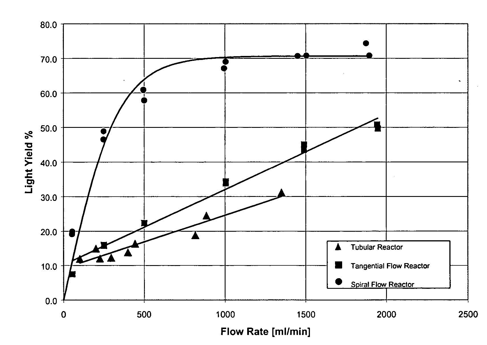
- however, the degree of mixing seems to level off at flow rates higher than 1000 ml/min. Since radial mixing is slightly better in the reactor with tangential inlet and outlet light yield is higher compared to a simple tubular reactor.
- Graph C shows the result of studies assessing the inactivation of Reo-
virus 3 in a solution of 5 mg/ml alpha1 proteinase inhibitor in the UV reactor with a spiral wound reaction chamber. It can be seen from this that Reo inactivation increases with increasing fluency and reaches a 4-log reduction at approximately 0.15 J/cm2. At the same time protein activity is not impacted, but it declines at fluencies above 0.15 J/cm2. The fluency value of 0.15 J/cm2 corresponds to a flow rate of 1000 ml/min. As noted in FIG. YYY mixing apparently approaches a limit at flow rates above 1000 ml/min in this device and plateaus. Further increase of flow rate (decreasing of fluency) thus decreases the overall residence time of the virus in the kill zone in the reactor and therefore leads to a reduced virus inactivation. At the same time protein activity declines with reduced flow rates (increasing fluency). This example suggests that there is an optimum flow rate where hydrodynamic conditions are appropriate to assure proper mixing, but at the same time overall residence time is still high enough to effectively kill virus and leave sufficient high protein activity. This flow rate depends not only on reactor design and configuration, as demonstrated, but also on the virus and protein properties and their respective concentrations, as described earlier. Therefore, optimal flow rates need to be determined experimentally for each given system.
- The invention has been described herein in terms of preferred embodiments, configurations, methodologies, and examples. It will be understood by those of skill in the art, however, that a variety of additions, deletions, and modifications might well be made to the illustrative embodiments without departing from the spirit and scope of the invention as set forth in the claims.
Claims (21)
Priority Applications (1)
| Application Number | Priority Date | Filing Date | Title |
|---|---|---|---|
| US11/079,934 US7695675B2 (en) | 2000-11-13 | 2005-03-14 | Method of inactivating microorganisms in a fluid using ultraviolet radiation |
Applications Claiming Priority (3)
| Application Number | Priority Date | Filing Date | Title |
|---|---|---|---|
| US71178000A | 2000-11-13 | 2000-11-13 | |
| US10/196,020 US20030049809A1 (en) | 2000-11-13 | 2002-07-16 | Method of inactivating microorganisms in a fluid using ultraviolet radiation |
| US11/079,934 US7695675B2 (en) | 2000-11-13 | 2005-03-14 | Method of inactivating microorganisms in a fluid using ultraviolet radiation |
Related Parent Applications (1)
| Application Number | Title | Priority Date | Filing Date |
|---|---|---|---|
| US10/196,020 Continuation US20030049809A1 (en) | 2000-11-13 | 2002-07-16 | Method of inactivating microorganisms in a fluid using ultraviolet radiation |
Publications (2)
| Publication Number | Publication Date |
|---|---|
| US20070003430A1 true US20070003430A1 (en) | 2007-01-04 |
| US7695675B2 US7695675B2 (en) | 2010-04-13 |
Family
ID=24859497
Family Applications (2)
| Application Number | Title | Priority Date | Filing Date |
|---|---|---|---|
| US10/196,020 Abandoned US20030049809A1 (en) | 2000-11-13 | 2002-07-16 | Method of inactivating microorganisms in a fluid using ultraviolet radiation |
| US11/079,934 Expired - Lifetime US7695675B2 (en) | 2000-11-13 | 2005-03-14 | Method of inactivating microorganisms in a fluid using ultraviolet radiation |
Family Applications Before (1)
| Application Number | Title | Priority Date | Filing Date |
|---|---|---|---|
| US10/196,020 Abandoned US20030049809A1 (en) | 2000-11-13 | 2002-07-16 | Method of inactivating microorganisms in a fluid using ultraviolet radiation |
Country Status (9)
| Country | Link |
|---|---|
| US (2) | US20030049809A1 (en) |
| EP (1) | EP1337280B1 (en) |
| JP (1) | JP4116429B2 (en) |
| CN (1) | CN1289150C (en) |
| AU (2) | AU2954502A (en) |
| CA (1) | CA2428332C (en) |
| DK (1) | DK1337280T3 (en) |
| HK (1) | HK1079716A1 (en) |
| WO (1) | WO2002038191A2 (en) |
Cited By (22)
| Publication number | Priority date | Publication date | Assignee | Title |
|---|---|---|---|---|
| US20080305018A1 (en) * | 2007-06-11 | 2008-12-11 | Albonia Innovative Technologies Ltd. | Photosterilization Reactor |
| DE202008003806U1 (en) | 2007-09-14 | 2009-02-12 | Nordmark Arzneimittel Gmbh & Co. Kg | Extract for the manufacture of pharmaceutical therapeutics and their use as food or food or dietary supplements |
| DE102007044100A1 (en) | 2007-09-14 | 2009-03-19 | Nordmark Arzneimittel Gmbh & Co. Kg | Reduction of virus and microorganism load in a biological extract useful for producing e.g. medicaments, comprises providing a solid material containing biological extract in form of suspension and powder and irradiating the extract |
| US20090258395A1 (en) * | 2008-04-14 | 2009-10-15 | Fennington Jr George J | Irx-2 modified manufacturing process |
| US20090294688A1 (en) * | 2005-09-20 | 2009-12-03 | Logistic Solutions Limited | Ultraviolet Radiation Treatment System |
| US20100097013A1 (en) * | 2008-09-19 | 2010-04-22 | Mathew Inskeep | Countertop decontaminating device |
| WO2011090885A3 (en) * | 2010-01-19 | 2011-11-17 | Ceramoptec Industries, Inc. | Enhanced anti-microbial pdt |
| WO2011156281A1 (en) * | 2010-06-07 | 2011-12-15 | Genzyme Corporation | Device for viral inactivation of liquid media |
| EP2424576A1 (en) * | 2009-04-28 | 2012-03-07 | Steriflow Limited | Uv liquid steriliser |
| US20120195791A1 (en) * | 2009-10-13 | 2012-08-02 | Bayer Pharma AG | Method for Deactivating Undesired Contaminations in Leech Extracts |
| US20120205552A1 (en) * | 2009-10-22 | 2012-08-16 | Jong Seop Shim | Microbicidal purification device employing ultraviolet light from which ultraviolet-light-irradiation dead areas have been eliminated |
| US20140131286A1 (en) * | 2012-11-09 | 2014-05-15 | International Business Machines Corporation | Large-scale electricity-less disinfection of fluent water |
| US9150434B2 (en) | 2012-11-09 | 2015-10-06 | International Business Machines Corporation | Electricity-less water disinfection |
| WO2017051322A1 (en) * | 2015-09-21 | 2017-03-30 | Rix Stuart Donovan | A device for the sterilization of liquids |
| WO2018153823A1 (en) | 2017-02-23 | 2018-08-30 | Merck Patent Gmbh | Flow-through fluid purification device |
| WO2018153827A1 (en) | 2017-02-23 | 2018-08-30 | Merck Patent Gmbh | Flow-through fluid purification device and means for accommodating a radiation source |
| US20190359505A1 (en) * | 2018-05-28 | 2019-11-28 | Phoenix Optronics Corp. | Piping device for improving effects of irradiating fluid |
| WO2020154331A1 (en) * | 2019-01-21 | 2020-07-30 | Greengield Jon | Treatment and agitation device for ultraviolet, temperature and gaseous controlled sterilization, curing and treatment of agricultural products including cannabis, and methods for treatment |
| US10894104B1 (en) * | 2020-09-11 | 2021-01-19 | PSYCURE Co., Ltd. | LED lighting device for sterilizing surface or space |
| US11433438B2 (en) * | 2018-12-18 | 2022-09-06 | Semes Co., Ltd. | Dissolved ozone removal unit, substrate treating apparatus including the same, and substrate treating method |
| WO2023115198A1 (en) * | 2021-12-22 | 2023-06-29 | Ghomi Osgoei Kamyar | Disinfection apparatus and method of use |
| US11786615B2 (en) | 2017-12-13 | 2023-10-17 | Bayer Aktiengesellschaft | Unit operation and use thereof |
Families Citing this family (75)
| Publication number | Priority date | Publication date | Assignee | Title |
|---|---|---|---|---|
| WO2003092746A1 (en) * | 2002-05-03 | 2003-11-13 | Gambro, Inc. | Fluid mixing and irradiation device and method of using the device especially for biological fluids |
| US20040005694A1 (en) * | 2002-05-08 | 2004-01-08 | Herbert Lutz | Light decontamination of fermentation media |
| US20030230477A1 (en) * | 2002-06-14 | 2003-12-18 | Fink Ronald G. | Environmental air sterilization system |
| AU2003201835B2 (en) * | 2002-07-17 | 2008-11-13 | Vast Light Ltd | Turbine-boosted ultraviolet-radiation sterilizing fluid processor |
| JP2004050169A (en) * | 2002-07-17 | 2004-02-19 | Vast Light Ltd | Bactericidal or algacidal liquid treating device with vortex acceleration ultraviolet ray |
| US6784440B2 (en) * | 2002-07-26 | 2004-08-31 | Boc, Inc. | Food sanitizing cabinet |
| US20040056201A1 (en) * | 2002-09-19 | 2004-03-25 | Fink Ronald G. | Food surface sanitation hood |
| CN1298422C (en) * | 2002-11-27 | 2007-02-07 | 株式会社日本光电科技 | Photochemical reaction device and process method thereof |
| GB0229870D0 (en) | 2002-12-21 | 2003-01-29 | Intersurgical Ltd | Improvements relating to closure devices |
| US7160566B2 (en) * | 2003-02-07 | 2007-01-09 | Boc, Inc. | Food surface sanitation tunnel |
| WO2004075931A2 (en) | 2003-02-27 | 2004-09-10 | Baxter International Inc. | Method for the validatable inactivation of pathogens in a biological fluid by irradiation |
| DE10312765A1 (en) * | 2003-03-21 | 2004-09-30 | Bayer Technology Services Gmbh | Continuous method for sterilization and, if required, virus inactivation of fluid, in particular, aqueous reaction media involves combined heat treatment and ultraviolet irradiation of the reaction medium |
| US8296071B2 (en) | 2004-03-15 | 2012-10-23 | Terumo Bct Biotechnologies, Llc | Methods for uniformly treating biological samples with electromagnetic radiation |
| US7993580B2 (en) | 2004-08-24 | 2011-08-09 | Baxter International Inc. | Methods for the inactivation of microorganisms in biological fluids, flow through reactors and methods of controlling the light sum dose to effectively inactivate microorganisms in batch reactors |
| JP2007144386A (en) | 2005-11-02 | 2007-06-14 | Toshiba Corp | Ultraviolet irradiation water-treatment apparatus |
| DE102006008125A1 (en) | 2006-02-20 | 2007-09-06 | Bayer Technology Services Gmbh | Cleanable spiral modules |
| DE102006018824A1 (en) | 2006-04-22 | 2007-10-25 | Bayer Technology Services Gmbh | Disposable bioreactor |
| WO2007147097A2 (en) | 2006-06-16 | 2007-12-21 | Drexel University | Fluid treatment using plasma technology |
| EP2527302B1 (en) | 2006-11-14 | 2018-05-16 | Atlantium Technologies Ltd. | Apparatus for liquid disinfection using light transparent conduit |
| US7652265B2 (en) * | 2006-12-11 | 2010-01-26 | General Electric Company | Air treatment system |
| CN102099105A (en) * | 2008-07-15 | 2011-06-15 | 特洛伊科技有限公司 | Fluid treatment system |
| EP2394963B1 (en) * | 2008-11-21 | 2016-02-17 | The University of Tokushima | Ultraviolet sterilization device for outdoor water |
| US8017073B2 (en) | 2008-11-28 | 2011-09-13 | Life Spring Limited Partnership | High intensity air purifier |
| FR2941866B1 (en) | 2009-02-09 | 2011-05-13 | Maco Pharma Sa | METHOD FOR MODIFYING THE PROPERTIES OF A FLUID BY IRRADIATION AND SYSTEM FOR ITS IMPLEMENTATION |
| DE102009009108B3 (en) * | 2009-02-16 | 2010-06-17 | Bayer Technology Services Gmbh | Method and device for connecting a flexible profiled hollow cylinder with a cylindrical body, as well as irradiation modules produced thereafter |
| EP2284126A1 (en) | 2009-08-13 | 2011-02-16 | Koninklijke Philips Electronics N.V. | Device comprising flow guides and a source for emitting ultraviolet light |
| US9162903B2 (en) * | 2010-03-30 | 2015-10-20 | Blutec, Llc | Photo-catalyzing fluid mobilizing system and method |
| KR100971177B1 (en) * | 2010-04-07 | 2010-07-20 | (주)유브이플러스 | Ultraviolet rays sterilizer for fruid having poor ultraviolet rays transmission |
| GB201006753D0 (en) | 2010-04-22 | 2010-06-09 | Biotest Ag | Process for preparing an immunolobulin composition |
| WO2012067918A1 (en) * | 2010-11-17 | 2012-05-24 | Kci Licensing, Inc. | Reduced-pressure systems and methods employing an ultraviolet light source for reducing bioburden |
| CA2860158A1 (en) | 2011-01-07 | 2012-07-12 | Somerset Group Enterprises, Inc. | Modular extracorporeal systems and methods for treating blood-borne diseases |
| GB2494448A (en) * | 2011-09-09 | 2013-03-13 | Steriflow Ltd | Ultra-violet liquid steriliser |
| US9375525B2 (en) * | 2012-01-09 | 2016-06-28 | Somerset Group Enterprises, Inc. | Modular extracorporeal systems and methods for treating blood-borne diseases |
| US8968578B1 (en) * | 2012-03-02 | 2015-03-03 | Verity Farms LLC | Water treatment system and method |
| CN104735980A (en) * | 2012-08-14 | 2015-06-24 | 中国电力株式会社 | Method for stopping attachment-period larvae from swimming or crawling |
| RU2015126762A (en) * | 2012-12-18 | 2017-01-25 | Караг Аг | DEVICE AND METHOD FOR PASTERIZATION OF BREAST MILK |
| US20140221692A1 (en) | 2013-02-04 | 2014-08-07 | Chevron Phillips Chemical Company Lp | Flow Reactor Vessels and Reactor Systems |
| WO2015126982A2 (en) | 2014-02-18 | 2015-08-27 | Rolf Engelhard | High efficiency ultra-violet reactor |
| EP2918294A1 (en) | 2014-03-11 | 2015-09-16 | Bayer Technology Services GmbH | Device and method for continuous viral inactivation |
| US11140893B2 (en) | 2014-03-24 | 2021-10-12 | The Chugoku Electric Power Co., Inc. | Method for stopping swimming or crawling of adhesion-stage larvae |
| EP3124441B1 (en) | 2014-03-24 | 2020-04-22 | The Chugoku Electric Power Co., Inc. | Method for killing pteriomorphia and barnacles using light irradiation |
| US20150284265A1 (en) * | 2014-04-03 | 2015-10-08 | Eaton Corporation | Ultraviolet fluid treatment system |
| EP2957177A1 (en) | 2014-06-16 | 2015-12-23 | Carag AG | Device for pasteurization of human milk |
| USD843554S1 (en) | 2014-10-14 | 2019-03-19 | Rolf Engelhard | Air purifier |
| CN104255909A (en) * | 2014-10-14 | 2015-01-07 | 荣成炭谷有限公司 | Sterilization method and equipment for milk |
| US9265876B1 (en) * | 2014-10-22 | 2016-02-23 | Hemalux Technologies LLC | Systems and methods for pathogen inactivation in blood using UV irradiation while minimizing heat transfer thereto |
| CN106793769B (en) | 2014-12-08 | 2020-10-23 | 中国电力株式会社 | Method for inhibiting adhesion of ampullaria gigas |
| US11134671B2 (en) | 2015-03-27 | 2021-10-05 | The Chugoku Electric Power Co., Inc. | Method for preventing settlement of sessile organisms |
| EP3088006A1 (en) | 2015-04-28 | 2016-11-02 | Bayer Technology Services GmbH | Method for continuous viral inactivation in a microreactor |
| US11518969B2 (en) * | 2015-05-14 | 2022-12-06 | University Of South Africa | Waste beer recovery |
| MY194952A (en) * | 2015-07-29 | 2022-12-28 | Semb Eco R&D Pte Ltd | Method and system for applying superimposed time-varying frequency electromagnetic wave to target object or target region |
| JP6654832B2 (en) * | 2015-09-03 | 2020-02-26 | 日機装株式会社 | Sterilizer |
| TWI565487B (en) | 2015-09-25 | 2017-01-11 | 財團法人工業技術研究院 | Sterilization apparatus |
| TWD179237S (en) | 2016-03-31 | 2016-11-01 | 財團法人工業技術研究院 | Portion of container |
| CN109071272B (en) * | 2016-04-28 | 2022-02-15 | 联合利华知识产权控股有限公司 | Device for UV-treatment of aqueous fluids |
| SG11201901220XA (en) | 2016-08-16 | 2019-03-28 | Genzyme Corp | Methods of processing a fluid including a recombinant therapeutic protein and use thereof |
| US11312642B2 (en) | 2017-03-31 | 2022-04-26 | Industrial Technology Research Institute | Fluid sterilizing device |
| WO2018184100A1 (en) * | 2017-04-04 | 2018-10-11 | University Health Network | Apparatus and methods for irradiating organ perfusates |
| JP7121054B2 (en) * | 2017-05-26 | 2022-08-17 | アキューバ、テクノロジーズ、インコーポレーテッド | Fluid sterilization apparatus and method |
| JP6892788B2 (en) * | 2017-05-26 | 2021-06-23 | ウシオ電機株式会社 | Sterilization method, sterilization equipment |
| IL253336A0 (en) * | 2017-07-05 | 2017-09-28 | Koren Mordechai | Radiation treatment system and method |
| CN107496950B (en) * | 2017-08-18 | 2021-02-02 | 广州市众为生物技术有限公司 | Method for inactivating virus in protein solution by ultraviolet irradiation |
| DK179693B1 (en) * | 2017-09-21 | 2019-03-27 | Lyras ApS | Photobioreactor for bactericidal treatment of fluids |
| EP3498106A1 (en) | 2017-12-13 | 2019-06-19 | Bayer Healthcare LLC | Unit operation and use thereof |
| TWI641411B (en) * | 2018-02-01 | 2018-11-21 | 匠萌技研股份有限公司 | Drinking fountain instant sterilization structure |
| US11832606B1 (en) * | 2019-02-20 | 2023-12-05 | Scanlogx, Inc. | Organism eradication system and method of use |
| KR102213392B1 (en) * | 2019-03-22 | 2021-02-08 | 경북대학교 산학합력단 | Method for microbial quorum quenching by light irradiation and method for controlling biological pollution |
| TW202128567A (en) | 2019-07-31 | 2021-08-01 | 美商通路實業集團國際公司 | Water treatment system |
| NL2024320B1 (en) * | 2019-11-27 | 2021-08-30 | Dinnissen B V | Ultraviolet radiation-based surface disinfection and/or surface processing system |
| US20230064241A1 (en) | 2020-02-03 | 2023-03-02 | Merck Patent Gmbh | Modular incubation chamber and method of virus inactivation |
| DE102020108265A1 (en) * | 2020-03-25 | 2021-09-30 | Hytecon Ag | Device for disinfecting a fluid |
| US11116858B1 (en) | 2020-05-01 | 2021-09-14 | Uv Innovators, Llc | Ultraviolet (UV) light emission device employing visible light for target distance guidance, and related methods of use, particularly suited for decontamination |
| KR20230107657A (en) | 2020-11-14 | 2023-07-17 | 마크 안소니 인터내셔날 에스알엘 | How to sterilize fermented beverages |
| CN114057346B (en) * | 2021-11-22 | 2022-09-13 | 山东新生泰水处理设备股份有限公司 | Water purification equipment with large-range disinfection function and use method thereof |
| WO2023106971A1 (en) * | 2021-12-07 | 2023-06-15 | Гаррий Дмитриевич IVASHCHENKO | Device for reducing pathogens in blood components |
Citations (4)
| Publication number | Priority date | Publication date | Assignee | Title |
|---|---|---|---|---|
| US4321919A (en) * | 1979-12-11 | 1982-03-30 | Leukocyte Research, Inc. | Method and system for externally treating human blood |
| US4769131A (en) * | 1986-05-09 | 1988-09-06 | Pure Water Technologies | Ultraviolet radiation purification system |
| US5466425A (en) * | 1994-07-08 | 1995-11-14 | Amphion International, Limited | Biological decontamination system |
| US6570167B1 (en) * | 1998-01-29 | 2003-05-27 | Kenneth Ray Bryer | Apparatus for treating a liquid |
Family Cites Families (11)
| Publication number | Priority date | Publication date | Assignee | Title |
|---|---|---|---|---|
| GB639467A (en) * | 1946-07-10 | 1950-06-28 | Michel Pequignot | Improved apparatus for treating fluids by radiation |
| US2636991A (en) | 1950-05-12 | 1953-04-28 | Hanovia Chemical & Mfg Co | Method and apparatus for irradiating liquids |
| GB8513170D0 (en) * | 1985-05-24 | 1985-06-26 | Still & Sons Ltd W M | Water purifiers |
| WO1995013853A1 (en) | 1993-11-16 | 1995-05-26 | Whitehall Water Filtration Systems | Water treatment device |
| CA2132930A1 (en) * | 1993-12-03 | 1995-06-04 | Louis Szabo | Uv water sterilizer with turbulence generator |
| CA2221289C (en) * | 1995-05-17 | 2003-10-21 | Hans Muller | Apparatus for the irradiation of body fluids by ultraviolet light |
| AU3250395A (en) * | 1995-08-30 | 1997-03-19 | Uv Systems Technology Inc. | Ultraviolet sterilizing system for wastewater |
| AUPO566097A0 (en) * | 1997-03-17 | 1997-04-10 | Browne, John Phillip | Fluid mixer and water oxygenator incorporating same |
| GB9821342D0 (en) * | 1998-10-02 | 1998-11-25 | Common Services Agency | Device for treatment of biological fluids |
| US6916452B1 (en) * | 1999-10-12 | 2005-07-12 | Hydrozone, Ltd. | Sterilization of liquids using ultra-violet light |
| GB0007681D0 (en) * | 2000-03-31 | 2000-05-17 | Iatros Ltd | Micro-organism inactivation system |
-
2001
- 2001-11-12 CN CNB018219233A patent/CN1289150C/en not_active Expired - Lifetime
- 2001-11-12 EP EP01990404.4A patent/EP1337280B1/en not_active Expired - Lifetime
- 2001-11-12 DK DK01990404.4T patent/DK1337280T3/en active
- 2001-11-12 WO PCT/EP2001/013058 patent/WO2002038191A2/en active Application Filing
- 2001-11-12 JP JP2002540772A patent/JP4116429B2/en not_active Expired - Lifetime
- 2001-11-12 CA CA2428332A patent/CA2428332C/en not_active Expired - Lifetime
- 2001-11-12 AU AU2954502A patent/AU2954502A/en active Pending
- 2001-11-12 AU AU2002229545A patent/AU2002229545B2/en not_active Expired
-
2002
- 2002-07-16 US US10/196,020 patent/US20030049809A1/en not_active Abandoned
-
2005
- 2005-03-14 US US11/079,934 patent/US7695675B2/en not_active Expired - Lifetime
- 2005-12-19 HK HK05111707A patent/HK1079716A1/en not_active IP Right Cessation
Patent Citations (4)
| Publication number | Priority date | Publication date | Assignee | Title |
|---|---|---|---|---|
| US4321919A (en) * | 1979-12-11 | 1982-03-30 | Leukocyte Research, Inc. | Method and system for externally treating human blood |
| US4769131A (en) * | 1986-05-09 | 1988-09-06 | Pure Water Technologies | Ultraviolet radiation purification system |
| US5466425A (en) * | 1994-07-08 | 1995-11-14 | Amphion International, Limited | Biological decontamination system |
| US6570167B1 (en) * | 1998-01-29 | 2003-05-27 | Kenneth Ray Bryer | Apparatus for treating a liquid |
Cited By (39)
| Publication number | Priority date | Publication date | Assignee | Title |
|---|---|---|---|---|
| US20090294688A1 (en) * | 2005-09-20 | 2009-12-03 | Logistic Solutions Limited | Ultraviolet Radiation Treatment System |
| US20080305018A1 (en) * | 2007-06-11 | 2008-12-11 | Albonia Innovative Technologies Ltd. | Photosterilization Reactor |
| US20100119654A1 (en) * | 2007-09-14 | 2010-05-13 | Raemsch Christian | Method for reducing the virus and micro-organism content of biological extracts which contain solids and extract produced according to the method |
| DE202008003806U1 (en) | 2007-09-14 | 2009-02-12 | Nordmark Arzneimittel Gmbh & Co. Kg | Extract for the manufacture of pharmaceutical therapeutics and their use as food or food or dietary supplements |
| DE102007044100A1 (en) | 2007-09-14 | 2009-03-19 | Nordmark Arzneimittel Gmbh & Co. Kg | Reduction of virus and microorganism load in a biological extract useful for producing e.g. medicaments, comprises providing a solid material containing biological extract in form of suspension and powder and irradiating the extract |
| WO2009036842A1 (en) | 2007-09-14 | 2009-03-26 | Nordmark Arzneimittel Gmbh & Co. Kg | Method for reducing the number of viruses and microorganisms in biological extracts containing solids, and extracts produced according to this method |
| US20090258395A1 (en) * | 2008-04-14 | 2009-10-15 | Fennington Jr George J | Irx-2 modified manufacturing process |
| WO2009137238A3 (en) * | 2008-04-14 | 2010-01-14 | Irx Therapeutics, Inc. | Irx-2 modified manufacturing process |
| US8470562B2 (en) * | 2008-04-14 | 2013-06-25 | Irx Therapeutics, Inc. | IRX-2 modified manufacturing process |
| US20100097013A1 (en) * | 2008-09-19 | 2010-04-22 | Mathew Inskeep | Countertop decontaminating device |
| US8581522B2 (en) | 2008-09-19 | 2013-11-12 | Mathew Inskeep | Countertop decontaminating device |
| EP2424576A1 (en) * | 2009-04-28 | 2012-03-07 | Steriflow Limited | Uv liquid steriliser |
| US20120195791A1 (en) * | 2009-10-13 | 2012-08-02 | Bayer Pharma AG | Method for Deactivating Undesired Contaminations in Leech Extracts |
| US8597568B2 (en) * | 2009-10-13 | 2013-12-03 | Bayer Pharma AG | Method for deactivating undesired contaminations in leech extracts |
| US9006682B2 (en) * | 2009-10-22 | 2015-04-14 | Jong Seop Shim | Microbicidal purification device employing ultraviolet light from which ultraviolet-light-irradiation dead areas have been eliminated |
| US20120205552A1 (en) * | 2009-10-22 | 2012-08-16 | Jong Seop Shim | Microbicidal purification device employing ultraviolet light from which ultraviolet-light-irradiation dead areas have been eliminated |
| GB2487035B (en) * | 2009-10-22 | 2015-01-28 | Jong Seop Shim | Microbicidal purification device employing ultraviolet light from which ultraviolet-light-irradiation dead areas have been eliminated |
| WO2011090885A3 (en) * | 2010-01-19 | 2011-11-17 | Ceramoptec Industries, Inc. | Enhanced anti-microbial pdt |
| EP2542305A4 (en) * | 2010-01-19 | 2013-10-02 | Ceramoptec Gmbh | Enhanced anti-microbial pdt |
| EP2542305A2 (en) * | 2010-01-19 | 2013-01-09 | CeramOptec GmbH | Enhanced anti-microbial pdt |
| CN103068408A (en) * | 2010-06-07 | 2013-04-24 | 建新公司 | Device for viral inactivation of liquid media |
| WO2011156281A1 (en) * | 2010-06-07 | 2011-12-15 | Genzyme Corporation | Device for viral inactivation of liquid media |
| AU2011265099B2 (en) * | 2010-06-07 | 2015-09-17 | Genzyme Corporation | Device for viral inactivation of liquid media |
| US9441196B2 (en) | 2010-06-07 | 2016-09-13 | Genzyme Corporation | Device for viral inactivation of liquid media |
| US20140131286A1 (en) * | 2012-11-09 | 2014-05-15 | International Business Machines Corporation | Large-scale electricity-less disinfection of fluent water |
| US9150434B2 (en) | 2012-11-09 | 2015-10-06 | International Business Machines Corporation | Electricity-less water disinfection |
| US9227855B2 (en) * | 2012-11-09 | 2016-01-05 | International Business Machines Corporation | Large-scale electricity-less disinfection of fluent water |
| WO2017051322A1 (en) * | 2015-09-21 | 2017-03-30 | Rix Stuart Donovan | A device for the sterilization of liquids |
| WO2018153823A1 (en) | 2017-02-23 | 2018-08-30 | Merck Patent Gmbh | Flow-through fluid purification device |
| WO2018153827A1 (en) | 2017-02-23 | 2018-08-30 | Merck Patent Gmbh | Flow-through fluid purification device and means for accommodating a radiation source |
| US11286179B2 (en) | 2017-02-23 | 2022-03-29 | Merck Patent Gmbh | Flow-through fluid purification device and means for accommodating a radiation source |
| US11565949B2 (en) | 2017-02-23 | 2023-01-31 | Merck Patent Gmbh | Flow-through fluid purification device |
| US11786615B2 (en) | 2017-12-13 | 2023-10-17 | Bayer Aktiengesellschaft | Unit operation and use thereof |
| US20190359505A1 (en) * | 2018-05-28 | 2019-11-28 | Phoenix Optronics Corp. | Piping device for improving effects of irradiating fluid |
| US11433438B2 (en) * | 2018-12-18 | 2022-09-06 | Semes Co., Ltd. | Dissolved ozone removal unit, substrate treating apparatus including the same, and substrate treating method |
| WO2020154331A1 (en) * | 2019-01-21 | 2020-07-30 | Greengield Jon | Treatment and agitation device for ultraviolet, temperature and gaseous controlled sterilization, curing and treatment of agricultural products including cannabis, and methods for treatment |
| US11154627B2 (en) | 2019-01-21 | 2021-10-26 | Jon Greenfield | Treatment and agitation device for ultraviolet, temperature and gaseous controlled sterilization, curing and treatment of agricultural products including cannabis, and methods for treatment |
| US10894104B1 (en) * | 2020-09-11 | 2021-01-19 | PSYCURE Co., Ltd. | LED lighting device for sterilizing surface or space |
| WO2023115198A1 (en) * | 2021-12-22 | 2023-06-29 | Ghomi Osgoei Kamyar | Disinfection apparatus and method of use |
Also Published As
| Publication number | Publication date |
|---|---|
| CN1655828A (en) | 2005-08-17 |
| CA2428332C (en) | 2010-05-25 |
| WO2002038191A2 (en) | 2002-05-16 |
| JP2004512905A (en) | 2004-04-30 |
| US7695675B2 (en) | 2010-04-13 |
| CA2428332A1 (en) | 2002-05-16 |
| CN1289150C (en) | 2006-12-13 |
| AU2954502A (en) | 2002-05-21 |
| EP1337280B1 (en) | 2013-09-04 |
| DK1337280T3 (en) | 2013-12-02 |
| US20030049809A1 (en) | 2003-03-13 |
| HK1079716A1 (en) | 2006-04-13 |
| EP1337280A2 (en) | 2003-08-27 |
| JP4116429B2 (en) | 2008-07-09 |
| WO2002038191A3 (en) | 2002-09-26 |
| AU2002229545B2 (en) | 2007-08-30 |
Similar Documents
| Publication | Publication Date | Title |
|---|---|---|
| US7695675B2 (en) | Method of inactivating microorganisms in a fluid using ultraviolet radiation | |
| US7381976B2 (en) | Monochromatic fluid treatment systems | |
| US6312931B1 (en) | Protecting molecules in biologically derived compositions while treating with high intensity broad-spectrum pulsed light | |
| CN101738254B (en) | Methods for the inactivation of microorganisms in biological fluids | |
| EP1938085B1 (en) | Ultraviolet light treatment chamber | |
| US6576201B1 (en) | Device and method for pathogen inactivation of therapeutic fluids with sterilizing radiation | |
| RU2466742C2 (en) | Method for pathogen inactivation in donor blood, blood plasma or concentrated erythorocytes in flexible containers by agitation | |
| AU2002306699A1 (en) | Monochromatic fluid treatment systems | |
| AU2001236787A1 (en) | Protecting molecules in biologically derived compositions while treating with broad-spectrum pulsed light | |
| KR20120017021A (en) | Ultraviolet light treatment chamber | |
| JP2008510538A5 (en) | ||
| JP2010172342A (en) | Method for validatable inactivation of pathogen in biological fluid by irradiation | |
| JPH11514277A (en) | An improved method for inactivating microorganisms using high-intensity pulsed polychromatic light | |
| MXPA06013633A (en) | Inactivation of a pathogen in a sample by a treatment with formalin and uv light. | |
| AU779193B2 (en) | Methods of inactivating pathogens using broad-spectrum pulsed light | |
| IES20000339A2 (en) | Apparatus for irradiating material | |
| AU2007237275A1 (en) | Method of inactivating microorganisms in a fluid using ultraviolet radiation | |
| JP2003225289A (en) | Method of refining contaminated biological liquid in state of holding protein | |
| US20030161756A1 (en) | Microdispersion treatment of a protein or pharmaceutical | |
| SE544918C2 (en) | A fluid treatment system with an UV lamp in a reactor | |
| AU2007202437A1 (en) | Monochromatic Fluid Treatment Systems | |
| Nag et al. | A REVIEW ON PULSED LIGHT TECHNOLOGIES IN WATER TREATMENT | |
| RO133743A2 (en) | Method and installation for decontamination of granular food products using ultraviolet light | |
| JPS6179461A (en) | Liquid sterilization method and apparatus |
Legal Events
| Date | Code | Title | Description |
|---|---|---|---|
| FEPP | Fee payment procedure |
Free format text: PAYOR NUMBER ASSIGNED (ORIGINAL EVENT CODE: ASPN); ENTITY STATUS OF PATENT OWNER: LARGE ENTITY |
|
| STCF | Information on status: patent grant |
Free format text: PATENTED CASE |
|
| FEPP | Fee payment procedure |
Free format text: PAYER NUMBER DE-ASSIGNED (ORIGINAL EVENT CODE: RMPN); ENTITY STATUS OF PATENT OWNER: LARGE ENTITY |
|
| FEPP | Fee payment procedure |
Free format text: PAYOR NUMBER ASSIGNED (ORIGINAL EVENT CODE: ASPN); ENTITY STATUS OF PATENT OWNER: LARGE ENTITY |
|
| AS | Assignment |
Owner name: BAYER INTELLECTUAL PROPERTY GMBH, GERMANY Free format text: ASSIGNMENT OF ASSIGNORS INTEREST;ASSIGNOR:BAYER TECHNOLOGY SERVICES GMBH;REEL/FRAME:031157/0347 Effective date: 20130812 |
|
| FPAY | Fee payment |
Year of fee payment: 4 |
|
| AS | Assignment |
Owner name: BAYER AKTIENGESELLSCHAFT, GERMANY Free format text: ASSIGNMENT OF ASSIGNORS INTEREST;ASSIGNOR:BAYER INTELLECTUAL PROPERTY GMBH;REEL/FRAME:040175/0253 Effective date: 20161005 |
|
| MAFP | Maintenance fee payment |
Free format text: PAYMENT OF MAINTENANCE FEE, 8TH YEAR, LARGE ENTITY (ORIGINAL EVENT CODE: M1552) Year of fee payment: 8 |
|
| MAFP | Maintenance fee payment |
Free format text: PAYMENT OF MAINTENANCE FEE, 12TH YEAR, LARGE ENTITY (ORIGINAL EVENT CODE: M1553); ENTITY STATUS OF PATENT OWNER: LARGE ENTITY Year of fee payment: 12 |