US20070194271A1 - 1,1,1,2,2,3,3,4,4-Nonafluro-4-methoxybutane refrigerant compositions comprising hydrofluorocarbon, and uses thereof - Google Patents
1,1,1,2,2,3,3,4,4-Nonafluro-4-methoxybutane refrigerant compositions comprising hydrofluorocarbon, and uses thereof Download PDFInfo
- Publication number
- US20070194271A1 US20070194271A1 US11/703,878 US70387807A US2007194271A1 US 20070194271 A1 US20070194271 A1 US 20070194271A1 US 70387807 A US70387807 A US 70387807A US 2007194271 A1 US2007194271 A1 US 2007194271A1
- Authority
- US
- United States
- Prior art keywords
- och
- composition
- weight percent
- canceled
- refrigerant
- Prior art date
- Legal status (The legal status is an assumption and is not a legal conclusion. Google has not performed a legal analysis and makes no representation as to the accuracy of the status listed.)
- Granted
Links
- 0 [1*]/C([2*])=C1\C(=O)O[C@]([5*])([6*])[C@]1([3*])[4*].[1*][C@@]1([2*])C(=O)O[C@]([5*])([6*])[C@]1([3*])[4*].[1*][C@@]1([2*])C(=O)O[C@]([7*])([8*])[C@]([5*])([6*])[C@]1([3*])[4*] Chemical compound [1*]/C([2*])=C1\C(=O)O[C@]([5*])([6*])[C@]1([3*])[4*].[1*][C@@]1([2*])C(=O)O[C@]([5*])([6*])[C@]1([3*])[4*].[1*][C@@]1([2*])C(=O)O[C@]([7*])([8*])[C@]([5*])([6*])[C@]1([3*])[4*] 0.000 description 3
- OALYTRUKMRCXNH-UHFFFAOYSA-N CCCCCC1CCC(=O)O1 Chemical compound CCCCCC1CCC(=O)O1 OALYTRUKMRCXNH-UHFFFAOYSA-N 0.000 description 2
- YGVNNINOXJVBJG-ONGXEEELSA-N C[C@H]1C[C@@H](CC2CCCCC2)C(=O)O1 Chemical compound C[C@H]1C[C@@H](CC2CCCCC2)C(=O)O1 YGVNNINOXJVBJG-ONGXEEELSA-N 0.000 description 2
- YHEFXCQGOIEIDG-RRKGBCIJSA-N CC(CC=C1C[C@@H](C)OC1=O)CC(C)(C)C Chemical compound CC(CC=C1C[C@@H](C)OC1=O)CC(C)(C)C YHEFXCQGOIEIDG-RRKGBCIJSA-N 0.000 description 1
- BDQJRNACUDIFLF-GLXQMMQGSA-N CC(CC[C@@H]1C[C@H](C)OC1=O)CC(C)(C)C Chemical compound CC(CC[C@@H]1C[C@H](C)OC1=O)CC(C)(C)C BDQJRNACUDIFLF-GLXQMMQGSA-N 0.000 description 1
- HJLVPHHUURFMLO-FLIBITNWSA-N CC1C/C(=C/C2CCCCC2)C(=O)O1 Chemical compound CC1C/C(=C/C2CCCCC2)C(=O)O1 HJLVPHHUURFMLO-FLIBITNWSA-N 0.000 description 1
- DALGWLJAONUZJZ-UHFFFAOYSA-N CC=C1CC(C)OC1=O Chemical compound CC=C1CC(C)OC1=O DALGWLJAONUZJZ-UHFFFAOYSA-N 0.000 description 1
- FEMNIQHEULUJGS-UHFFFAOYSA-N CCC=C1CC(C)OC1=O Chemical compound CCC=C1CC(C)OC1=O FEMNIQHEULUJGS-UHFFFAOYSA-N 0.000 description 1
- BHHYZKGIWKJVAL-UHFFFAOYSA-N CCCC=C1CC(C)OC1=O Chemical compound CCCC=C1CC(C)OC1=O BHHYZKGIWKJVAL-UHFFFAOYSA-N 0.000 description 1
- IPBFYZQJXZJBFQ-UHFFFAOYSA-N CCCCC1CCC(=O)O1 Chemical compound CCCCC1CCC(=O)O1 IPBFYZQJXZJBFQ-UHFFFAOYSA-N 0.000 description 1
- BEUIZLAUWLZVEB-UHFFFAOYSA-N CCCCC=C1CC(C)OC1=O Chemical compound CCCCC=C1CC(C)OC1=O BEUIZLAUWLZVEB-UHFFFAOYSA-N 0.000 description 1
- GHBSPIPJMLAMEP-UHFFFAOYSA-N CCCCCC1CCCC(=O)O1 Chemical compound CCCCCC1CCCC(=O)O1 GHBSPIPJMLAMEP-UHFFFAOYSA-N 0.000 description 1
- CAJHMRZCSCVDAF-UHFFFAOYSA-N CCCCCC=C1CC(C)OC1=O Chemical compound CCCCCC=C1CC(C)OC1=O CAJHMRZCSCVDAF-UHFFFAOYSA-N 0.000 description 1
- IFYYFLINQYPWGJ-UHFFFAOYSA-N CCCCCCC1CCC(=O)O1 Chemical compound CCCCCCC1CCC(=O)O1 IFYYFLINQYPWGJ-UHFFFAOYSA-N 0.000 description 1
- YZRXRLLRSPQHDK-UHFFFAOYSA-N CCCCCCC1CCCC(=O)O1 Chemical compound CCCCCCC1CCCC(=O)O1 YZRXRLLRSPQHDK-UHFFFAOYSA-N 0.000 description 1
- IBVDLVUXSDSVQF-UHFFFAOYSA-N CCCCCCC1CCOC1=O Chemical compound CCCCCCC1CCOC1=O IBVDLVUXSDSVQF-UHFFFAOYSA-N 0.000 description 1
- HRPVPEKIGWEWDV-UHFFFAOYSA-N CCCCCCC1CCOC1=O.CCCCCCC1COC(=O)C1 Chemical compound CCCCCCC1CCOC1=O.CCCCCCC1COC(=O)C1 HRPVPEKIGWEWDV-UHFFFAOYSA-N 0.000 description 1
- SPOJRVXZEMNXKH-UHFFFAOYSA-N CCCCCCC=C1CC(C)OC1=O Chemical compound CCCCCCC=C1CC(C)OC1=O SPOJRVXZEMNXKH-UHFFFAOYSA-N 0.000 description 1
- PHXATPHONSXBIL-UHFFFAOYSA-N CCCCCCCC1CCC(=O)O1 Chemical compound CCCCCCCC1CCC(=O)O1 PHXATPHONSXBIL-UHFFFAOYSA-N 0.000 description 1
- QRPLZGZHJABGRS-UHFFFAOYSA-N CCCCCCCC1CCCC(=O)O1 Chemical compound CCCCCCCC1CCCC(=O)O1 QRPLZGZHJABGRS-UHFFFAOYSA-N 0.000 description 1
- ABQLAMJAQZFPJI-UHFFFAOYSA-N CCCCCCCC1CCOC1=O Chemical compound CCCCCCCC1CCOC1=O ABQLAMJAQZFPJI-UHFFFAOYSA-N 0.000 description 1
- BWOFHOJKKOJDNL-UHFFFAOYSA-N CCCCCCCC=C1CC(C)OC1=O Chemical compound CCCCCCCC=C1CC(C)OC1=O BWOFHOJKKOJDNL-UHFFFAOYSA-N 0.000 description 1
- WGPCZPLRVAWXPW-UHFFFAOYSA-N CCCCCCCCC1CCC(=O)O1 Chemical compound CCCCCCCCC1CCC(=O)O1 WGPCZPLRVAWXPW-UHFFFAOYSA-N 0.000 description 1
- NQSHBZGHCFWUAY-UHFFFAOYSA-N CCCCCCCCC=C1CC(C)OC1=O Chemical compound CCCCCCCCC=C1CC(C)OC1=O NQSHBZGHCFWUAY-UHFFFAOYSA-N 0.000 description 1
- TUXWUKLVKDZOCT-UHFFFAOYSA-N CCCCCCCCCC=C1CC(C)OC1=O Chemical compound CCCCCCCCCC=C1CC(C)OC1=O TUXWUKLVKDZOCT-UHFFFAOYSA-N 0.000 description 1
- WMWYLWYBVPDZAO-NWDGAFQWSA-N CCCCCCCC[C@@H]1C[C@H](C)OC1=O Chemical compound CCCCCCCC[C@@H]1C[C@H](C)OC1=O WMWYLWYBVPDZAO-NWDGAFQWSA-N 0.000 description 1
- AQFUJAYDUNXOBV-CYBMUJFWSA-N CCCCCCCC[C@]1(C)CCC(=O)O1 Chemical compound CCCCCCCC[C@]1(C)CCC(=O)O1 AQFUJAYDUNXOBV-CYBMUJFWSA-N 0.000 description 1
- ZFKUTGNRVJOCIO-WDEREUQCSA-N CCCCCCC[C@@H]1C[C@H](C)OC1=O Chemical compound CCCCCCC[C@@H]1C[C@H](C)OC1=O ZFKUTGNRVJOCIO-WDEREUQCSA-N 0.000 description 1
- JHGNKGVPSGFWPG-VHSXEESVSA-N CCCCCC[C@@H]1C[C@H](C)OC1=O Chemical compound CCCCCC[C@@H]1C[C@H](C)OC1=O JHGNKGVPSGFWPG-VHSXEESVSA-N 0.000 description 1
- ALWUKGXLBSQSMA-LLVKDONJSA-N CCCCCC[C@]1(C)CCC(=O)O1 Chemical compound CCCCCC[C@]1(C)CCC(=O)O1 ALWUKGXLBSQSMA-LLVKDONJSA-N 0.000 description 1
- FYMCVWIOVWCVFX-DTWKUNHWSA-N CCCCC[C@@H]1C[C@H](C)OC1=O Chemical compound CCCCC[C@@H]1C[C@H](C)OC1=O FYMCVWIOVWCVFX-DTWKUNHWSA-N 0.000 description 1
- SLHHEERUKABFQC-JGVFFNPUSA-N CCCC[C@@H]1C[C@H](C)OC1=O Chemical compound CCCC[C@@H]1C[C@H](C)OC1=O SLHHEERUKABFQC-JGVFFNPUSA-N 0.000 description 1
- NMNZFIPBKPDLGC-NKWVEPMBSA-N CCC[C@@H]1C[C@H](C)OC1=O Chemical compound CCC[C@@H]1C[C@H](C)OC1=O NMNZFIPBKPDLGC-NKWVEPMBSA-N 0.000 description 1
- TVSURRUHJZSEFC-NTSWFWBYSA-N CC[C@@H]1C[C@H](C)OC1=O Chemical compound CC[C@@H]1C[C@H](C)OC1=O TVSURRUHJZSEFC-NTSWFWBYSA-N 0.000 description 1
- WLYUMBPDHPMKHM-RNFRBKRXSA-N [H][C@]12CCCC[C@@]1([H])C(=O)OC2 Chemical compound [H][C@]12CCCC[C@@]1([H])C(=O)OC2 WLYUMBPDHPMKHM-RNFRBKRXSA-N 0.000 description 1
Classifications
-
- C—CHEMISTRY; METALLURGY
- C09—DYES; PAINTS; POLISHES; NATURAL RESINS; ADHESIVES; COMPOSITIONS NOT OTHERWISE PROVIDED FOR; APPLICATIONS OF MATERIALS NOT OTHERWISE PROVIDED FOR
- C09K—MATERIALS FOR MISCELLANEOUS APPLICATIONS, NOT PROVIDED FOR ELSEWHERE
- C09K5/00—Heat-transfer, heat-exchange or heat-storage materials, e.g. refrigerants; Materials for the production of heat or cold by chemical reactions other than by combustion
- C09K5/02—Materials undergoing a change of physical state when used
- C09K5/04—Materials undergoing a change of physical state when used the change of state being from liquid to vapour or vice versa
- C09K5/041—Materials undergoing a change of physical state when used the change of state being from liquid to vapour or vice versa for compression-type refrigeration systems
- C09K5/044—Materials undergoing a change of physical state when used the change of state being from liquid to vapour or vice versa for compression-type refrigeration systems comprising halogenated compounds
- C09K5/045—Materials undergoing a change of physical state when used the change of state being from liquid to vapour or vice versa for compression-type refrigeration systems comprising halogenated compounds containing only fluorine as halogen
-
- C—CHEMISTRY; METALLURGY
- C09—DYES; PAINTS; POLISHES; NATURAL RESINS; ADHESIVES; COMPOSITIONS NOT OTHERWISE PROVIDED FOR; APPLICATIONS OF MATERIALS NOT OTHERWISE PROVIDED FOR
- C09K—MATERIALS FOR MISCELLANEOUS APPLICATIONS, NOT PROVIDED FOR ELSEWHERE
- C09K2205/00—Aspects relating to compounds used in compression type refrigeration systems
- C09K2205/10—Components
- C09K2205/11—Ethers
- C09K2205/112—Halogenated ethers
-
- C—CHEMISTRY; METALLURGY
- C09—DYES; PAINTS; POLISHES; NATURAL RESINS; ADHESIVES; COMPOSITIONS NOT OTHERWISE PROVIDED FOR; APPLICATIONS OF MATERIALS NOT OTHERWISE PROVIDED FOR
- C09K—MATERIALS FOR MISCELLANEOUS APPLICATIONS, NOT PROVIDED FOR ELSEWHERE
- C09K2205/00—Aspects relating to compounds used in compression type refrigeration systems
- C09K2205/22—All components of a mixture being fluoro compounds
-
- C—CHEMISTRY; METALLURGY
- C09—DYES; PAINTS; POLISHES; NATURAL RESINS; ADHESIVES; COMPOSITIONS NOT OTHERWISE PROVIDED FOR; APPLICATIONS OF MATERIALS NOT OTHERWISE PROVIDED FOR
- C09K—MATERIALS FOR MISCELLANEOUS APPLICATIONS, NOT PROVIDED FOR ELSEWHERE
- C09K2205/00—Aspects relating to compounds used in compression type refrigeration systems
- C09K2205/32—The mixture being azeotropic
Definitions
- the present invention relates to compositions suitable for use in refrigeration and air conditioning apparatuses, wherein the compositions comprise at least one hydrofluoroether and hydrofluorocarbon. Further, the present invention relates to compositions suitable for use in refrigeration and air-conditioning apparatus employing a centrifugal compressor.
- the compositions of the present invention may be azeotropic or near azeotropic in nature and are useful in processes for producing refrigeration or heat or as heat transfer fluids.
- HFC-134a Currently proposed replacement refrigerants for HFC-134a include HFC-152a, pure hydrocarbons such as butane or propane, or “natural” refrigerants such as CO 2 or ammonia. Many of these suggested replacements are toxic, flammable, and/or have low energy efficiency. Therefore, new alternatives are constantly being sought.
- the object of the present invention is to provide novel refrigerant compositions and heat transfer fluids that provide unique characteristics to meet the demands of low or zero ozone depletion potential and lower global warming potential as compared to current refrigerants.
- the present invention relates to refrigerant and heat transfer fluid compositions comprising C 4 F 9 OCH 3 and
- hydrofluorocarbon selected from the group consisting of:
- the present invention further relates to the above listed compositions specifically suitable for use in refrigeration or air conditioning apparatus employing a centrifugal compressor.
- the present invention further relates to the above listed compositions specifically suitable for use in refrigeration or air conditioning apparatus employing a 2-stage centrifugal compressor.
- the present invention further relates to the above listed compositions specifically suitable for use in refrigeration or air conditioning apparatus employing a single pass/single slab heat exchanger.
- the present invention further relates to azeotropic or near azeotropic refrigerant compositions. These compositions are useful in refrigeration or air conditioning apparatus. The compositions are also useful in refrigeration or air conditioning apparatus employing a centrifugal compressor.
- the present invention further relates to processes for producing refrigeration, heat, and transfer of heat from a heat source to a heat sink using the present inventive compositions.
- the refrigerant compositions of the present invention comprise hydrofluoroether (HFOC) and hydrofluorocarbon (HFC).
- HFOC hydrofluoroether
- HFC hydrofluorocarbon
- the hydrofluoroether of the present invention comprises C 4 F 9 OCH 3 .
- This hydrofluoroether compound may comprise a mixture of several isomers including CF 3 CF 2 CF 2 CF 2 OCH 3 (1,1,1,2,2,3,3,4,4-nonalfuoro-4-methoxybutane, Cas reg no. 163702-07-6) and (CF 3 ) 2 CFCF 2 OCH 3 (2-(difluoromethoxymethyl)-1,1,1,2,3,3,3-heptafluoropropane, Cas reg no.163702-08-7).
- C 4 F 9 OCH 3 is available commercially from 3MTM (St. Paul, Minn.).
- the hydrofluorocarbons of the present invention comprise compounds containing hydrogen, fluorine and carbon. These hydrofluorocarbons may be represented by the formula C x H 2x+2 ⁇ y F y or C x H 2x ⁇ y F y . In the formulas, x may equal 3 to 8 and y may equal 1-17.
- the hydrofluorocarbons may be straight chain, branched chain or cyclic; saturated or unsaturated compounds having from about 3 to 8 carbon atoms. Representative hydrofluorocarbons are listed in Table 1. TABLE 1 CAS Reg. Compound Chemical Formula Chemical Name No.
- C 4 F 9 OCH 3 is a mixture of isomers as indicated in Table 1 and is available commercially from 3MTM (St. Paul, Minn.).
- compositions of the present invention have no ozone depletion potential and low global warming potential.
- lightly fluorinated hydrofluorocarbons and fluoroethers, alone or in mixtures will have global warming potentials lower than many HFC refrigerants currently in use.
- compositions of the present invention that are mixtures may be prepared by any convenient method to combine the desired amounts of the individual components.
- a preferred method is to weigh the desired component amounts and thereafter combine the components in an appropriate vessel. Agitation may be used, if desired.
- compositions of the present invention include:
- the refrigerant or heat transfer compositions of the present invention may be azeotropic or near azeotropic compositions.
- An azeotropic composition is a liquid admixture of two or more substances that has a constant boiling point that may be above or below the boiling points of the individual components. As such an azeotropic composition will not fractionate within the refrigeration or air conditioning system during operation, which may reduce efficiency of the system. Additionally, an azeotropic composition will not fractionate upon leakage from the refrigeration or air conditioning system. In the situation where one component of a mixture is flammable, fractionation during leakage could lead to a flammable composition either within the system or outside of the system.
- a near azeotropic composition is a substantially constant boiling, liquid admixture of two or more substances that behaves essentially as a single substance.
- One way to characterize a near azeotropic composition is that the vapor produced by partial evaporation or distillation of the liquid has substantially the same composition as the liquid from which it was evaporated or distilled, that is, the admixture distills/refluxes without substantial composition change.
- Another way to characterize a near azeotropic composition is that the bubble point vapor pressure and the dew point vapor pressure of the composition at a particular temperature are substantially the same.
- a composition is near azeotropic if, after 50 weight percent of the composition is removed, such as by evaporation or boiling off, the difference in vapor pressure between the original composition and the composition remaining after 50 weight percent of the original composition has been removed is less than about 10 percent.
- azeotropic refrigerant compositions of the present invention are listed in Table 2.
- Table 2 Azeotrope Concentration Azeotrope Component A Component B Wt % A Wt % B BP (° C.) C 4 F 9 OCH 3 HFC-263fa 40.8 59.2 42.4 C 4 F 9 OCH 3 HFC-392qfe 49.3 50.7 59.0 C 4 F 9 OCH 3 HFC-4-11-2sc 63.8 36.2 54.3 C 4 F 9 OCH 3 HFC-5-12-3m 91.0 9.0 59.6 C 4 F 9 OCH 3 HFC-C354cc 7.2 92.8 50.0
- Additional compounds from the list in Table 1 may be added to the binary compositions of the present invention to form ternary or higher order compositions.
- compositions of the present invention may further comprise about 0.01 weight percent to about 5 weight percent of a thermal stabilizer such as nitromethane.
- compositions of the present invention may further comprise an ultra-violet (UV) dye and optionally a solubilizing agent.
- UV dye is a useful component for detecting leaks of the refrigerant composition by permitting one observe the fluorescence of the dye in in the refrigerant or heat transfer fluid composition at a leak point in or the vicinity of refrigeration or air-conditioning apparatus. One may obserce the fluorosence of the dye under an ultra-violet light. Solubilizing agents may be needed due to poor solubility of such UV dyes in some refrigerants.
- ultra-violet dye is meant a UV fluorescent composition that absorbs light in the ultra-violet or “near” ultra-violet region of the electromagnetic spectrum.
- the fluorescence produced by the UV fluorescent dye under illumination by a UV light that emits radiation with wavelength anywhere from 10 nanometer to 750 nanometer may be detected. Therefore, if refrigerant containing such a UV fluorescent dye is leaking from a given point in a refrigeration or air conditioning apparatus, the fluorescence can be detected at the leak point.
- UV fluorescent dyes include but are not limited to naphthalimides, perylenes, coumarins, anthracenes, phenanthracenes, xanthenes, thioxanthenes, naphthoxanthenes, fluoresceins, and derivatives or combinations thereof.
- Solubilizing agents of the present invention comprise at least one compound selected from the group consisting of hydrocarbons, hydrocarbon ethers, polyoxyalkylene glycol ethers, amides, nitriles, ketones, chlorocarbons, esters, lactones, aryl ethers, fluoroethers and 1,1,1-trifluoroalkanes.
- Hydrocarbon solubilizing agents of the present invention comprise hydrocarbons, including straight chained, branched chain or cyclic alkanes or alkenes containing 5 or fewer carbon atoms and only hydrogen with no other functional groups.
- Representative hydrocarbon solubilizing agents comprise propane, propylene, cyclopropane, n-butane, isobutane, and n-pentane. It should be noted that if the refrigerant is a hydrocarbon, then the solubilizing agent may not be the same hydrocarbon.
- Hydrocarbon ether solubilizing agents of the present invention comprise ethers containing only carbon, hydrogen and oxygen, such as dimethyl ether (DME).
- DME dimethyl ether
- Polyoxyalkylene glycol ether solubilizing agents of the present invention are represented by the formula R 1 [(OR 2 ) x OR 3 ] y , wherein: x is an integer from 1-3; y is an integer from 1-4; R 1 is selected from hydrogen and aliphatic hydrocarbon radicals having 1 to 6 carbon atoms and y bonding sites; R 2 is selected from aliphatic hydrocarbylene radicals having from 2 to 4 carbon atoms; R 3 is selected from hydrogen and aliphatic and alicyclic hydrocarbon radicals having from 1 to 6 carbon atoms; at least one of R 1 and R 3 is said hydrocarbon radical; and wherein said polyoxyalkylene glycol ethers have a molecular weight of from about 100 to about 300 atomic mass units.
- x is preferably 1-2; y is preferably 1; R 1 and R 3 are preferably independently selected from hydrogen and aliphatic hydrocarbon radicals having 1 to 4 carbon atoms; R 2 is preferably selected from aliphatic hydrocarbylene radicals having from 2 or 3 carbon atoms, most preferably 3 carbon atoms; the polyoxyalkylene glycol ether molecular weight is preferably from about 100 to about 250 atomic mass units, most preferably from about 125 to about 250 atomic mass units.
- the R 1 and R 3 hydrocarbon radicals having 1 to 6 carbon atoms may be linear, branched or cyclic.
- R 1 and R 3 hydrocarbon radicals include methyl, ethyl, propyl, isopropyl, butyl, isobutyl, sec-butyl, tert-butyl, pentyl, isopentyl, neopentyl, tert-pentyl, cyclopentyl, and cyclohexyl.
- R 1 and R 3 are preferably aliphatic hydrocarbon radicals having 1 to 4 carbon atoms, most preferably 1 carbon atom.
- the R 2 aliphatic hydrocarbylene radicals having from 2 to 4 carbon atoms form repeating oxyalkylene radicals —(OR 2 ) x — that include oxyethylene radicals, oxypropylene radicals, and oxybutylene radicals.
- the oxyalkylene radical comprising R 2 in one polyoxyalkylene glycol ether solubilizing agent molecule may be the same, or one molecule may contain different R 2 oxyalkylene groups.
- the present polyoxyalkylene glycol ether solubilizing agents preferably comprise at least one oxypropylene radical.
- R 1 is an aliphatic or alicyclic hydrocarbon radical having 1 to 6 carbon atoms and y bonding sites
- the radical may be linear, branched or cyclic.
- Representative R 1 aliphatic hydrocarbon radicals having two bonding sites include, for example, an ethylene radical, a propylene radical, a butylene radical, a pentylene radical, a hexylene radical, a cyclopentylene radical and a cyclohexylene radical.
- R 1 aliphatic hydrocarbon radicals having three or four bonding sites include residues derived from polyalcohols, such as trimethylolpropane, glycerin, pentaerythritol, 1,2,3-trihydroxycyclohexane and 1,3,5-trihydroxycyclohexane, by removing their hydroxyl radicals.
- Representative polyoxyalkylene glycol ether solubilizing agents include but are not limited to: CH 3 OCH 2 CH(CH 3 )O(H or CH 3 ) (propylene glycol methyl (or dimethyl) ether), CH 3 O[CH 2 CH(CH 3 )O] 2 (H or CH 3 ) (dipropylene glycol methyl (or dimethyl) ether), CH 3 O[CH 2 CH(CH 3 )O] 3 (H or CH 3 ) (tripropylene glycol methyl (or dimethyl) ether), C 2 H 5 OCH 2 CH(CH 3 )O(H or C 2 H 5 ) (propylene glycol ethyl (or diethyl) ether), C 2 H 5 O[CH 2 CH(CH 3 )O] 2 (H or C 2 H 5 ) (dipropylene glycol ethyl (or diethyl) ether), C 2 H 5 O[CH 2 CH(CH 3 )O] 3 (H or C 2 H 5
- Amide solubilizing agents of the present invention comprise those represented by the formulae R 1 CONR 2 R 3 and cyclo-[R 4 CON(R 5 )—], wherein R 1 , R 2 , R 3 and R 5 are independently selected from aliphatic and alicyclic hydrocarbon radicals having from 1 to 12 carbon atoms; R 4 is selected from aliphatic hydrocarbylene radicals having from 3 to 12 carbon atoms; and wherein said amides have a molecular weight of from about 100 to about 300 atomic mass units. The molecular weight of said amides is preferably from about 160 to about 250 atomic mass units.
- R 1 , R 2 , R 3 and R 5 may optionally include substituted hydrocarbon radicals, that is, radicals containing non-hydrocarbon substituents selected from halogens (e.g., fluorine, chlorine) and alkoxides (e.g. methoxy).
- R 1 , R 2 , R 3 and R 5 may optionally include heteroatom-substituted hydrocarbon radicals, that is, radicals, which contain the atoms nitrogen (aza-), oxygen (oxa-) or sulfur (thia-) in a radical chain otherwise composed of carbon atoms.
- amide solubilizing agents consist of carbon, hydrogen, nitrogen and oxygen.
- R 1 , R 2 , R 3 and R 5 aliphatic and alicyclic hydrocarbon radicals include methyl, ethyl, propyl, isopropyl, butyl, isobutyl, sec-butyl, tert-butyl, pentyl, isopentyl, neopentyl, tert-pentyl, cyclopentyl, cyclohexyl, heptyl, octyl, nonyl, decyl, undecyl, dodecyl and their configurational isomers.
- a preferred embodiment of amide solubilizing agents are those wherein R 4 in the aforementioned formula cyclo-[R 4 CON(R 5 )—] may be represented by the hydrocarbylene radical (CR 6 R 7 ) n , in other words, the formula: cyclo-[(CR 6 R 7 ) n CON(R 5 )—] wherein: the previously-stated values for molecular weight apply; n is an integer from 3 to 5; R 5 is a saturated hydrocarbon radical containing 1 to 12 carbon atoms; R 6 and R 7 are independently selected (for each n) by the rules previously offered defining R 1-3 .
- R 6 and R 7 are preferably hydrogen, or contain a single saturated hydrocarbon radical among the n methylene units, and R 5 is a saturated hydrocarbon radical containing 3 to 12 carbon atoms.
- R 5 is a saturated hydrocarbon radical containing 3 to 12 carbon atoms.
- amide solubilizing agents include but are not limited to: 1-octylpyrrolidin-2-one, 1-decylpyrrolidin-2-one, 1-octyl-5-methylpyrrolidin-2-one, 1-butylcaprolactam, 1-cyclohexylpyrrolid in-2-one, 1-butyl-5-methylpiperid-2-one, 1-pentyl-5-methylpiperid-2-one, 1-hexylcaprolactam, 1-hexyl-5-methylpyrrolidin-2-one, 5-methyl-1-pentylpiperid-2-one, 1,3-dimethylpiperid-2-one, 1-methylcaprolactam, 1-butyl-pyrrolidin-2-one, 1,5-dimethylpiperid-2-one, 1-decyl-5-methylpyrrolidin-2-one, 1-dodecylpyrrolid-2-one, N,N-dibutylformamide and N,N-diisopropylacetamide.
- Ketone solubilizing agents of the present invention comprise ketones represented by the formula R 1 COR 2 , wherein R 1 and R 2 are independently selected from aliphatic, alicyclic and aryl hydrocarbon radicals having from 1 to 12 carbon atoms, and wherein said ketones have a molecular weight of from about 70 to about 300 atomic mass units.
- R 1 and R 2 in said ketones are preferably independently selected from aliphatic and alicyclic hydrocarbon radicals having 1 to 9 carbon atoms.
- the molecular weight of said ketones is preferably from about 100 to 200 atomic mass units.
- R 1 and R 2 may together form a hydrocarbylene radical connected and forming a five, six, or seven-membered ring cyclic ketone, for example, cyclopentanone, cyclohexanone, and cycloheptanone.
- R 1 and R 2 may optionally include substituted hydrocarbon radicals, that is, radicals containing non-hydrocarbon substituents selected from halogens (e.g., fluorine, chlorine) and alkoxides (e.g. methoxy).
- R 1 and R 2 may optionally include heteroatom-substituted hydrocarbon radicals, that is, radicals, which contain the atoms nitrogen (aza-), oxygen (keto-, oxa-) or sulfur (thia-) in a radical chain otherwise composed of carbon atoms.
- heteroatom-substituted hydrocarbon radicals that is, radicals, which contain the atoms nitrogen (aza-), oxygen (keto-, oxa-) or sulfur (thia-) in a radical chain otherwise composed of carbon atoms.
- no more than three non-hydrocarbon substituents and heteroatoms, and preferably no more than one, will be present for each 10 carbon atoms in R 1 and R 2 , and the presence of any such non-hydrocarbon substituents and heteroatoms must be considered in applying the aforementioned molecular weight limitations.
- R 1 and R 2 aliphatic, alicyclic and aryl hydrocarbon radicals in the general formula R 1 COR 2 include methyl, ethyl, propyl, isopropyl, butyl, isobutyl, sec-butyl, tert-butyl, pentyl, isopentyl, neopentyl, tert-pentyl, cyclopentyl, cyclohexyl, heptyl, octyl, nonyl, decyl, undecyl, dodecyl and their configurational isomers, as well as phenyl, benzyl, cumenyl, mesityl, tolyl, xylyl and phenethyl.
- ketone solubilizing agents include but are not limited to: 2-butanone, 2-pentanone, acetophenone, butyrophenone, hexanophenone, cyclohexanone, cycloheptanone, 2-heptanone, 3-heptanone, 5-methyl-2-hexanone, 2-octanone, 3-octanone, diisobutyl ketone, 4-ethylcyclohexanone, 2-nonanone, 5-nonanone, 2-decanone, 4-decanone, 2-decalone, 2-tridecanone, dihexyl ketone and dicyclohexyl ketone.
- Nitrile solubilizing agents of the present invention comprise nitriles represented by the formula R 1 CN, wherein R 1 is selected from aliphatic, alicyclic or aryl hydrocarbon radicals having from 5 to 12 carbon atoms, and wherein said nitriles have a molecular weight of from about 90 to about 200 atomic mass units.
- R 1 in said nitrile solubilizing agents is preferably selected from aliphatic and alicyclic hydrocarbon radicals having 8 to 10 carbon atoms.
- the molecular weight of said nitrile solubilizing agents is preferably from about 120 to about 140 atomic mass units.
- R 1 may optionally include substituted hydrocarbon radicals, that is, radicals containing non-hydrocarbon substituents selected from halogens (e.g., fluorine, chlorine) and alkoxides (e.g. methoxy).
- R 1 may optionally include heteroatom-substituted hydrocarbon radicals, that is, radicals, which contain the atoms nitrogen (aza-), oxygen (keto-, oxa-) or sulfur (thia-) in a radical chain otherwise composed of carbon atoms.
- R 1 aliphatic, alicyclic and aryl hydrocarbon radicals in the general formula R 1 CN include pentyl, isopentyl, neopentyl, tert-pentyl, cyclopentyl, cyclohexyl, heptyl, octyl, nonyl, decyl, undecyl, dodecyl and their configurational isomers, as well as phenyl, benzyl, cumenyl, mesityl, tolyl, xylyl and phenethyl.
- nitrile solubilizing agents include but are not limited to: 1-cyanopentane, 2,2-dimethyl-4-cyanopentane, 1-cyanohexane, 1-cyanoheptane, 1-cyanooctane, 2-cyanooctane, 1-cyanononane, 1-cyanodecane, 2-cyanodecane, 1-cyanoundecane and 1-cyanododecane.
- Chlorocarbon solubilizing agents of the present invention comprise chlorocarbons represented by the formula RCI x , wherein; x is selected from the integers 1 or 2; R is selected from aliphatic and alicyclic hydrocarbon radicals having 1 to 12 carbon atoms; and wherein said chlorocarbons have a molecular weight of from about 100 to about 200 atomic mass units.
- the molecular weight of said chlorocarbon solubilizing agents is preferably from about 120 to 150 atomic mass units.
- R aliphatic and alicyclic hydrocarbon radicals in the general formula RCl x include methyl, ethyl, propyl, isopropyl, butyl, isobutyl, sec-butyl, tert-butyl, pentyl, isopentyl, neopentyl, tert-pentyl, cyclopentyl, cyclohexyl, heptyl, octyl, nonyl, decyl, undecyl, dodecyl and their configurational isomers.
- Representative chlorocarbon solubilizing agents include but are not limited to: 3-(chloromethyl)pentane, 3-chloro-3-methylpentane, 1-chlorohexane, 1,6-dichlorohexane, 1-chloroheptane, 1-chlorooctane, 1-chlorononane, 1-chlorodecane, and 1,1,1-trichlorodecane.
- Ester solubilizing agents of the present invention comprise esters represented by the general formula R 1 CO 2 R 2 , wherein R 1 and R 2 are independently selected from linear and cyclic, saturated and unsaturated, alkyl and aryl radicals.
- Preferred esters consist essentially of the elements C, H and O, have a molecular weight of from about 80 to about 550 atomic mass units.
- esters include but are not limited to: (CH 3 ) 2 CHCH 2 OOC(CH 2 ) 2-4 OCOCH 2 CH(CH 3 ) 2 (diisobutyl dibasic ester), ethyl hexanoate, ethyl heptanoate, n-butyl propionate, n-propyl propionate, ethyl benzoate, di-n-propyl phthalate, benzoic acid ethoxyethyl ester, dipropyl carbonate, “Exxate 700” (a commercial C 7 alkyl acetate), “Exxate 800” (a commercial C 8 alkyl acetate), dibutyl phthalate, and tert-butyl acetate.
- Lactone solubilizing agents of the present invention comprise lactones represented by structures [A], [B], and [C]: These lactones contain the functional group —CO 2 — in a ring of six (A), or preferably five atoms (B), wherein for structures [A] and [B], R 1 , through R 8 are independently selected from hydrogen or linear, branched, cyclic, bicyclic, saturated and unsaturated hydrocarbyl radicals. Each R 1 , though R 8 may be connected forming a ring with another R 1 , through R 8 .
- the lactone may have an exocyclic alkylidene group as in structure [C], wherein R 1 .
- R 6 are independently selected from hydrogen or linear, branched, cyclic, bicyclic, saturated and unsaturated hydrocarbyl radicals. Each R 1 . though R 6 may be connected forming a ring with another R 1 , through R 6 .
- the lactone solubilizing agents have a molecular weight range of from about 80 to about 300 atomic mass units, preferred from about 80 to about 200 atomic mass units.
- lactone solubilizing agents include but are not limited to the compounds listed in Table 4. TABLE 4 Molecular Molecular Additive Molecular Structure Formula Weight (amu) (E,Z)-3-ethylidene-5-methyl- dihydro-furan-2-one C 7 H 10 O 2 126 (E,Z)-3-propylidene-5-methyl- dihydro-furan-2-one C 8 H 12 O 2 140 (E,Z)-3-butylidene-5-methyl- dihydro-furan-2-one C 9 H 14 O 2 154 (E,Z)-3-pentylidene-5-methyl- dihydro-furan-2-one C 10 H 16 O 2 168 (E,Z)-3-Hexylidene-5-methyl- dihydro-furan-2-one C 11 H 18 O 2 182 (E,Z)-3-Heptylidene-5-methyl- dihydro-furan-2-one C 12 H 20 O 2 196 (E,Z)-3-octylidene-5
- Lactone solubilizing agents generally have a kinematic viscosity of less than about 7 centistokes at 40° C.
- gamma-undecalactone has kinematic viscosity of 5.4 centistokes and cis-(3-hexyl-5-methyl)dihydrofuran-2-one has viscosity of 4.5 centistokes both at 40° C.
- Lactone solubilizing agents may be available commercially or prepared by methods as described in U.S. provisional patent application 10/910,495 (inventors being P. J. Fagan and C. J. Brandenburg), filed Aug. 3, 2004, incorporated herein by reference.
- Aryl ether solubilizing agents of the present invention further comprise aryl ethers represented by the formula R 1 OR 2 , wherein: R 1 is selected from aryl hydrocarbon radicals having from 6 to 12 carbon atoms; R 2 is selected from aliphatic hydrocarbon radicals having from 1 to 4 carbon atoms; and wherein said aryl ethers have a molecular weight of from about 100 to about 150 atomic mass units.
- R 1 aryl radicals in the general formula R 1 OR 2 include phenyl, biphenyl, cumenyl, mesityl, tolyl, xylyl, naphthyl and pyridyl.
- R 2 aliphatic hydrocarbon radicals in the general formula R 1 OR 2 include methyl, ethyl, propyl, isopropyl, butyl, isobutyl, sec-butyl and tert-butyl.
- Representative aromatic ether solubilizing agents include but are not limited to: methyl phenyl ether (anisole), 1,3-dimethyoxybenzene, ethyl phenyl ether and butyl phenyl ether.
- Fluoroether solubilizing agents of the present invention comprise those represented by the general formula R 1 OCF 2 CF 2 H, wherein R 1 is selected from aliphatic and alicyclic hydrocarbon radicals having from about 5 to about 15 carbon atoms, preferably primary, linear, saturated, alkyl radicals.
- Representative fluoroether solubilizing agents include but are not limited to: C 8 H 17 OCF 2 CF 2 H and C 6 H 13 OCF 2 CF 2 H. It should be noted that if the refrigerant is a fluoroether, then the solubilizing agent may not be the same fluoroether.
- 1,1,1-Trifluoroalkane solubilizing agents of the present invention comprise 1,1,1-trifluoroalkanes represented by the general formula CF 3 R 1 , wherein R 1 is selected from aliphatic and alicyclic hydrocarbon radicals having from about 5 to about 15 carbon atoms, preferably primary, linear, saturated, alkyl radicals.
- Representative 1,1,1-trifluoroalkane solubilizing agents include but are not limited to: 1,1,1-trifluorohexane and 1,1,1-trifluorododecane.
- Solubilizing agents of the present invention may be present as a single compound, or may be present as a mixture of more than one solubilizing agent. Mixtures of solubilizing agents may contain two solubilizing agents from the same class of compounds, say two lactones, or two solubilizing agents from two different classes, such as a lactone and a polyoxyalkylene glycol ether.
- compositions comprising refrigerant and UV fluorescent dye
- from about 0.001 weight percent to about 1.0 weight percent of the composition is UV dye, preferably from about 0.005 weight percent to about 0.5 weight percent, and most preferably from 0.01 weight percent to about 0.25 weight percent.
- the UV fluorescent dye could be dissolved in the refrigerant itself thereby not requiring any specialized method for introduction to the refrigeration or air conditioning apparatus.
- the present invention relates to compositions including UV fluorescent dye, which may be introduced into the system directly in the refrigerant.
- the inventive compositions will allow the storage and transport of dye-containing refrigerant even at low temperatures while maintaining the dye in solution.
- compositions comprising refrigerant, UV fluorescent dye and solubilizing agent, from about 1 to about 50 weight percent, preferably from about 2 to about 25 weight percent, and most preferably from about 5 to about 15 weight percent of the combined composition is solubilizing agent in the refrigerant.
- the UV fluorescent dye is present in a concentration from about 0.001 weight percent to about 1.0 weight percent in the refrigerant, preferably from 0.005 weight percent to about 0.5 weight percent, and most preferably from 0.01 weight percent to about 0.25 weight percent.
- commonly used refrigeration system additives may optionally be added, as desired, to compositions of the present invention in order to enhance performance and system stability.
- These additives are known within the field of refrigeration, and include, but are not limited to, anti wear agents, extreme pressure lubricants, corrosion and oxidation inhibitors, metal surface deactivators, free radical scavengers, and foam control agents,.
- these additives are present in the inventive compositions in small amounts relative to the overall composition. Typically concentrations of from less than about 0.1 weight percent to as much as about 3 weight percent of each additive are used. These additives are selected on the basis of the individual system requirements.
- additives include members of the triaryl phosphate family of EP (extreme pressure) lubricity additives, such as butylated triphenyl phosphates (BTPP), or other alkylated triaryl phosphate esters, e.g. Syn-0-Ad 8478 from Akzo Chemicals, tricrecyl phosphates and related compounds. Additionally, the metal dialkyl dithiophosphates (e.g. zinc dialkyl dithiophosphate (or ZDDP), Lubrizol 1375 and other members of this family of chemicals may be used in compositions of the present invention.
- Other antiwear additives include natural product oils and asymmetrical polyhydroxyl lubrication additives, such as Synergol TMS (International Lubricants).
- stabilizers such as anti oxidants, free radical scavengers, and water scavengers may be employed.
- Compounds in this category can include, but are not limited to, butylated hydroxy toluene (BHT) and epoxides.
- Solubilizing agents such as ketones may have an objectionable odor, which can be masked by addition of an odor masking agent or fragrance.
- odor masking agents or fragrances may include Evergreen, Fresh Lemon, Cherry, Cinnamon, Peppermint, Floral or Orange Peel or sold by Intercontinental Fragrance, as well as d-limonene and pinene.
- Such odor masking agents may be used at concentrations of from about 0.001% to as much as about 15% by weight based on the combined weight of odor masking agent and solubilizing agent.
- the present invention further relates to a method of using the refrigerant or heat transfer fluid compositions further comprising ultraviolet fluorescent dye, and optionally, solubilizing agent, in refrigeration or air conditioning apparatus.
- the method comprises introducing the refrigerant or heat transfer fluid composition into the refrigeration or air conditioning apparatus. This may be done by dissolving the UV fluorescent dye in the refrigerant or heat transfer fluid composition in the presence of a solubilizing agent and introducing the combination into the apparatus. Alternatively, this may be done by combining solubilizing agent and and UV fluorescent dye and introducing said combination into refrigeration or air conditioning apparatus containing refrigerant and/or heat transfer fluid. The resulting composition is may be used in the refrigeration or air conditioning apparatus.
- the present invention further relates to a method of using the refrigerant or heat transfer fluid compositions comprising ultraviolet fluorescent dye to detect leaks.
- the presence of the dye in the compositions allows for detection of leaking refrigerant in the refrigeration or air conditioning apparatus.
- Leak detection helps to address, resolve or prevent inefficient operation of the apparatus or system or equipment failure.
- Leak detection also helps one contain chemicals used in the operation of the apparatus.
- the method comprises providing the composition comprising refrigerant, ultra-violet fluorescent dye as described herein, and optionally, a solubilizing agent as described herein, to refrigeration and air conditioning apparatus and employing a suitable means for detecting the UV fluorescent dye-containing refrigerant.
- suitable means for detecting the dye include, but are not limited to, ultra-violet lamp, often referred to as a “black light” or “blue light”. Such ultra-violet lamps are commercially available from numerous sources specifically designed for this purpose.
- the present invention further relates to a method of using the compositions of the present invention for producing refrigeration or heat, wherein the method comprises producing refrigeration by evaporating said composition in the vicinity of a body to be cooled and thereafter condensing said composition; or producing heat by condensing the said composition in the vicinity of the body to be heated and thereafter evaporating said composition.
- thermodynamics wherein a cooling medium, such as a refrigerant, goes through a cycle so that it can be recovered for reuse.
- a cooling medium such as a refrigerant
- Commonly used cycles include vapor-compression, absorption, steam-jet or steam-ejector, and air.
- Vapor-compression refrigeration systems include an evaporator, a compressor, a condenser, and an expansion device.
- a vapor-compression cycle re-uses refrigerant in multiple steps producing a cooling effect in one step and a heating effect in a different step.
- the cycle can be described simply as follows. Liquid refrigerant enters an evaporator through an expansion device, and the liquid refrigerant boils in the evaporator at a low temperature to form a gas and produce cooling. The low-pressure gas enters a compressor where the gas is compressed to raise its pressure and temperature. The higher-pressure (compressed) gaseous refrigerant then enters the condenser in which the refrigerant condenses and discharges its heat to the environment. The refrigerant returns to the expansion device through which the liquid expands from the higher-pressure level in the condenser to the low-pressure level in the evaporator, thus repeating the cycle.
- compressors there are various types of compressors that may be used in refrigeration applications.
- Compressors can be generally classified as reciprocating, rotary, jet, centrifugal, scroll, screw or axial-flow, depending on the mechanical means to compress the fluid, or as positive-displacement (e.g., reciprocating, scroll or screw) or dynamic (e.g., centrifugal or jet), depending on how the mechanical elements act on the fluid to be compressed.
- positive-displacement e.g., reciprocating, scroll or screw
- dynamic e.g., centrifugal or jet
- a centrifugal type compressor is the preferred equipment for the present refrigerant compositions.
- a centrifugal compressor uses rotating elements to accelerate the refrigerant radially, and typically includes an impeller and diffuser housed in a casing.
- Centrifugal compressors usually take fluid in at an impeller eye, or central inlet of a circulating impeller, and accelerate it radially outward. Some static pressure rise occurs in the impeller, but most of the pressure rise occurs in the diffuser section of the casing, where velocity is converted to static pressure.
- Each impeller-diffuser set is a stage of the compressor.
- Centrifugal compressors are built with from 1 to 12 or more stages, depending on the final pressure desired and the volume of refrigerant to be handled.
- the pressure ratio, or compression ratio, of a compressor is the ratio of absolute discharge pressure to the absolute inlet pressure.
- Pressure delivered by a centrifugal compressor is practically constant over a relatively wide range of capacities.
- Positive displacement compressors draw vapor into a chamber, and the chamber decreases in volume to compress the vapor. After being compressed, the vapor is forced from the chamber by further decreasing the volume of the chamber to zero or nearly zero.
- a positive displacement compressor can build up a pressure, which is limited only by the volumetric efficiency and the strength of the parts to withstand the pressure.
- a centrifugal compressor Unlike a positive displacement compressor, a centrifugal compressor depends entirely on the centrifugal force of the high-speed impeller to compress the vapor passing through the impeller. There is no positive displacement, but rather what is called dynamic-compression.
- the pressure a centrifugal compressor can develop depends on the tip speed of the impeller. Tip speed is the speed of the impeller measured at its tip and is related to the diameter of the impeller and its revolutions per minute.
- the capacity of the centrifugal compressor is determined by the size of the passages through the impeller. This makes the size of the compressor more dependent on the pressure required than the capacity.
- centrifugal compressor Because of its high-speed operation, a centrifugal compressor is fundamentally a high volume, low-pressure machine.
- a centrifugal compressor works best with a low-pressure refrigerant, such as trichlorofluoromethane (CFC-11) or 1,2,2-trichlorotrifluoroethane (CFC-113).
- centrifugal compressors typically operate at 3000 to 7000 revolutions per minute (rpm).
- Small turbine centrifugal compressors are designed for high speeds, from about 40,000 to about 70,000 (rpm), and have small impeller sizes, typically less than 0.15 meters.
- a multi-stage impeller may be used in a centrifugal compressor to improve compressor efficiency thus requiring less power in use.
- the discharge of the first stage impeller goes to the suction intake of a second impeller.
- Both impellers may operate by use of a single shaft (or axle).
- Each stage can build up a compression ratio of about 4 to 1; that is, the absolute discharge pressure can be four times the absolute suction pressure.
- An example of a two-stage centrifugal compressor system, in this case for automotive applications, is described in U.S. Pat. No. 5,065,990, incorporated herein by reference.
- compositions of the present invention suitable for use in a refrigeration or air conditioning apparatus employing a centrifugal compressor comprise at least one of:
- compositions are also suitable for use in two-stage centrifugal compressor apparatus and suitable for use in refrigeration or air conditioning apparatus employing a single slab/single pass heat exchanger:
- compositions of the present invention may be used in stationary air-conditioning, heat pumps or mobile air-conditioning and refrigeration systems.
- Stationary air conditioning and heat pump applications include window, ductless, ducted, packaged terminal, chillers and commercial, including packaged rooftop.
- Refrigeration applications include domestic or home refrigerators and freezers, ice machines, self-contained coolers and freezers, walk-in coolers and freezers and transport refrigeration systems.
- compositions of the present invention may additionally be used in air-conditioning, heating and refrigeration systems that employ fin and tube heat exchangers, microchannel heat exchangers and vertical or horizontal single pass tube or plate type heat exchangers.
- microchannel heat exchangers may not be ideal for the low pressure refrigerant compositions of the present invention.
- the low operating pressure and density result in high flow velocities and high frictional losses in all components.
- the evaporator design may be modified.
- a single slab/single pass heat exchanger arrangement may be used. Therefore, a preferred heat exchanger for the low pressure refrigerants of the present invention is a single slab/single pass heat exchanger.
- compositions of the present invention are particularly useful in small turbine centrifugal compressors, which can be used in auto and window air conditioning or heat pump as well as other applications.
- These high efficiency miniature centrifugal compressors may be driven by an electric motor and can therefore be operated independently of the engine speed.
- a constant compressor speed allows the system to provide a relatively constant cooling capacity at all engine speeds. This provides an opportunity for efficiency improvements especially at higher engine speeds as compared to a conventional R-134a automobile air-conditioning system. When the cycling operation of conventional systems at high driving speeds is taken into account, the advantage of these low pressure systems becomes even greater.
- Some of the low pressure refrigerant fluids of the present invention may be suitable as drop-in replacements for CFC-113 in existing centrifugal equipment.
- the present invention relates to a process for producing refrigeration comprising evaporating the compositions of the present invention in the vicinity of a body to be cooled, and thereafter condensing said compositions.
- the present invention further relates to a process for producing heat comprising condensing the compositions of the present invention in the vicinity of a body to be heated, and thereafter evaporating said compositions.
- the present invention further relates to a process for transfer of heat from a heat source to a heat sink wherein the compositions of the present invention serve as heat transfer fluids.
- Said process for heat transfer comprises transferring the compositions of the present invention from a heat source to a heat sink.
- Heat transfer fluids are utilized to transfer, move or remove heat from one space, location, object or body to a different space, location, object or body by radiation, conduction, or convection.
- a heat transfer fluid may function as a secondary coolant by providing means of transfer for cooling (or heating) from a remote refrigeration (or heating) system.
- the heat transfer fluid may remain in a constant state throughout the transfer process (i.e., not evaporate or condense).
- evaporative cooling processes may utilize heat transfer fluids as well.
- a heat source may be defined as any space, location, object or body from which it is desirable to transfer, move or remove heat.
- heat sources may be spaces (open or enclosed) requiring refrigeration or cooling, such as refrigerator or freezer cases in a supermarket, building spaces requiring air conditioning, or the passenger compartment of an automobile requiring air conditioning.
- a heat sink may be defined as any space, location, object or body capable of absorbing heat.
- a vapor compression refrigeration system is one example of such a heat sink.
- a vessel is charged with an initial composition at a specified temperature, and the initial vapor pressure of the composition is measured.
- the composition is allowed to leak from the vessel, while the temperature is held constant, until 50 weight percent of the initial composition is removed, at which time the vapor pressure of the composition remaining in the vessel is measured.
- Table 4 The results are summarized in Table 4 below.
- compositions of the present invention are azeotropic or near-azeotrope. Where an azeotrope is present, the data show compositions of the present invention have an initial vapor pressure higher than the vapor pressure of either pure component.
- Tip speed can be estimated by making some fundamental relationships for refrigeration equipment that use centrifugal compressors.
- V 2 tangential velocity of refrigerant leaving impeller (tip speed), m/s
- v 1 tangential velocity of refrigerant entering impeller, m/s
- H i Difference in enthalpy of the refrigerant from a saturated vapor at the evaporating conditions to saturated condensing conditions, kJ/kg.
- Equation 8 is based on some fundamental assumptions, it provides a good estimate of the tip speed of the impeller and provides an important way to compare tip speeds of refrigerants.
Abstract
Disclosed herein are refrigerant or heat transfer fluid compositions further comprising fluoroether, 1,1,1,2,2,3,3,4,4-nonafluoro-4-methoxybutane, and hydrofluorocarbon, which are useful in refrigeration or air conditioning apparatus or as heat transfer fluids. The compositions of the present invention are also useful in centrifugal compressor apparatus that employ two-stage compressors or single slab/single pass heat exchangers.
Description
- This application claims the priority benefit of U.S. Provisional Application 60/536,819, filed Jan. 14, 2004, and U.S. Provisional Application 60/537,453, filed Jan. 15, 2004, and U.S. Provisional Application 60/549,978, filed Mar. 4, 2004, and U.S. Provisional Application 60/575,037, filed May 26, 2004, and U.S. Provisional Application 60/584,785, filed Jun. 29, 2004.
- 1. Field of the Invention.
- The present invention relates to compositions suitable for use in refrigeration and air conditioning apparatuses, wherein the compositions comprise at least one hydrofluoroether and hydrofluorocarbon. Further, the present invention relates to compositions suitable for use in refrigeration and air-conditioning apparatus employing a centrifugal compressor. The compositions of the present invention may be azeotropic or near azeotropic in nature and are useful in processes for producing refrigeration or heat or as heat transfer fluids.
- 2. Description of Related Art.
- The refrigeration industry has been working for the past few decades to find replacement refrigerants for the ozone depleting chlorofluorocarbons (CFCs) and hydrochlorofluorocarbons (HCFCs) being phased out as a result of the Montreal Protocol. The solution for most refrigerant producers has been the commercialization of hydrofluorocarbon (HFC) refrigerants. The new HFC refrigerants, HFC-134a being the most widely used at this time, have zero ozone depletion potential and thus are not affected by the current regulatory phase out as a result of the Montreal Protocol.
- Further environmental regulations may ultimately cause global phase out of certain HFC refrigerants. Currently, the automobile industry is facing regulations relating to global warming potential for refrigerants used in mobile air-conditioning. Therefore, there is a great current need to identify new refrigerants with reduced global warming potential for the automobile air-conditioning market. Should the regulations be more broadly applied in the future, an even greater need will be felt for refrigerants that can be used in all areas of the refrigeration and air-conditioning industry.
- Currently proposed replacement refrigerants for HFC-134a include HFC-152a, pure hydrocarbons such as butane or propane, or “natural” refrigerants such as CO2 or ammonia. Many of these suggested replacements are toxic, flammable, and/or have low energy efficiency. Therefore, new alternatives are constantly being sought.
- The object of the present invention is to provide novel refrigerant compositions and heat transfer fluids that provide unique characteristics to meet the demands of low or zero ozone depletion potential and lower global warming potential as compared to current refrigerants.
- The present invention relates to refrigerant and heat transfer fluid compositions comprising C4F9OCH3 and
- a hydrofluorocarbon selected from the group consisting of:
- 1,1,2,2,3-pentafluoropropane;
- 1,1,1,3,3-pentafluoropropane;
- 1,1,3-trifluoropropane;
- 1,3-difluoropropane;
- 2-(difluoromethyl)-1,1 1,2,3,3-hexafluoropropane;
- 1,1,2,2,3,3,4,4-octafluorobutane;
- 1,1,1,2,2,4-hexafluorobutane;
- 1,1,1,3,3-pentafluorobutane;
- 1,1-difluorobutane;
- 1,3-difluoro-2-methylpropane;
- 1,2-difluoro-2-methylpropane;
- 1,2-difluorobutane;
- 1,3-difluorobutane;
- 1,4-difluorobutane;
- 2,3-difluorobutane;
- 1,1,1,2,3,3,4,4-octafluoro-2-(trifluoromethyl)butane;
- 1,1,1,2,2,3,3,4,4,5,5-undecafluoropentane;
- 1,1,1,2,2,3,4,5,5,5-decafluoropentane;
- 1,1,1 ,2,2,3,3,5,5,5-decafluoropentane;
- 1,1,1,4,4,4-hexafluoro-2-(trifluoromethyl)butane;
- 1,1,1-trifluoropentane;
- 1,1,1-trifluoro-3-methylbutane;
- 1,1-difluoropentane;
- 1,2-difluoropentane;
- 2,2-difluoropentane;
- 1,1,1-trifluorohexane;
- 1,1,1,2,2,3,3,4,4,5,5,6,6-tridecafluorohexane;
- 1,1,1,2,2,5,5,5-octafluoro-4-(trifluoromethyl)pentane; and
- 1,1,2,2,-tetrafluorocyclobutane.
- The present invention further relates to the above listed compositions specifically suitable for use in refrigeration or air conditioning apparatus employing a centrifugal compressor.
- The present invention further relates to the above listed compositions specifically suitable for use in refrigeration or air conditioning apparatus employing a 2-stage centrifugal compressor.
- The present invention further relates to the above listed compositions specifically suitable for use in refrigeration or air conditioning apparatus employing a single pass/single slab heat exchanger.
- The present invention further relates to azeotropic or near azeotropic refrigerant compositions. These compositions are useful in refrigeration or air conditioning apparatus. The compositions are also useful in refrigeration or air conditioning apparatus employing a centrifugal compressor.
- The present invention further relates to processes for producing refrigeration, heat, and transfer of heat from a heat source to a heat sink using the present inventive compositions.
- The refrigerant compositions of the present invention comprise hydrofluoroether (HFOC) and hydrofluorocarbon (HFC).
- The hydrofluoroether of the present invention comprises C4F9OCH3. This hydrofluoroether compound may comprise a mixture of several isomers including CF3CF2CF2CF2OCH3 (1,1,1,2,2,3,3,4,4-nonalfuoro-4-methoxybutane, Cas reg no. 163702-07-6) and (CF3)2CFCF2OCH3 (2-(difluoromethoxymethyl)-1,1,1,2,3,3,3-heptafluoropropane, Cas reg no.163702-08-7). C4F9OCH3 is available commercially from 3M™ (St. Paul, Minn.).
- The hydrofluorocarbons of the present invention comprise compounds containing hydrogen, fluorine and carbon. These hydrofluorocarbons may be represented by the formula CxH2x+2−yFy or CxH2x−yFy. In the formulas, x may equal 3 to 8 and y may equal 1-17. The hydrofluorocarbons may be straight chain, branched chain or cyclic; saturated or unsaturated compounds having from about 3 to 8 carbon atoms. Representative hydrofluorocarbons are listed in Table 1.
TABLE 1 CAS Reg. Compound Chemical Formula Chemical Name No. HFC-245ca CHF2CF2CH2F 1,1,2,2,3-pentafluoropropane 679-86-7 HFC-245fa CF3CH2CHF2 1,1,1,3,3-pentafluoropropane 460-73-1 HFC-263fa CHF2CH2CH2F 1,1,3-trifluoropropane 24270-67-5 HFC-272fa CH2FCH2CH2F 1,3-difluoropropane 462-39-5 HFC-338mpy CHF2CF(CF3)CHF2 2-(difluoromethyl)-1,1,1,2,3,3- 65781-21-7 hexafluoropropane HFC-338pcc CHF2CF2CF2CHF2 1,1,2,2,3,3,4,4-octafluorobutane 377-36-6 HFC-356mcf CF3CF2CH2CH2F 1,1,1,2,2,4-hexafluorobutane 161791-33-9 HFC-365mfc CF3CH2CF2CH3 1,1,1,3,3-pentafluorobutane 406-58-6 HFC-392p CF2HCH2CH2CH3 1,1-difluorobutane 2358-38-5 HFC-392qqz (CH2F)2CHCH3 1,3-difluoro-2-methylpropane 62126-93-6 HFC-392qy CH2FCF(CH3)2 1,2-difluoro-2-methylpropane 62126-92-5 HFC-392qe CH2FCHFCH2CH3 1,2-difluorobutane 686-65-7 HFC-392qfe CH2FCH2CHFCH3 1,3-difluorobutane 691-42-9 HFC-392qff CH2FCH2CH2CH2F 1,4-difluorobutane 372-90-7 HFC-392see CH3CHFCHFCH3 2,3-difluorobutane 666-21-7 HFC-42-11mmyc (CF3)2CFCF2CHF2 1,1,1,2,3,3,4,4-octafluoro-2- 1960-20-9 (trifluoromethyl)butane HFC-42-11p CHF2CF2CF2CF2CF3 1,1,2,2,3,3,4,4,5,5- 375-61-1 undecafluoropentane HFC-43-10mee CF3CHFCHFCF2CF3 1,1,1,2,2,3,4,5,5,5-decafluoropentane 138495-42-8 HFC-43-10mf CF3CH2CF2CF2CF3 1,1,1,2,2,3,3,5,5,5-decafluoropentane 755-45-3 HFC-449mmzf (CF3)2CHCH2CF3 1,1,1,4,4,4-hexafluoro-2- 367-53-3 (trifluoromethyl)butane HFC-4-10-3m CF3(CH2)3CH3 1,1,1-trifluoropentane 402-82-6 HFC-4-10-3mfsz CF3CH2CH(CH3)2 1,1,1-trifluoro-3-methylbutane 406-49-5 HFC-4-11-2p CHF2(CH2)3CH3 1,1-difluoropentane 62127-40-6 HFC-4-11-2qe CH2FCHF(CH2)2CH3 1,2-difluoropentane 62126-94-7 HFC-4-11-2sc CH3CF2CH2CH2CH3 2,2-difluoropentane 371-65-3 HFC-5-12-3m CF3(CH2)4CH3 1,1,1-trifluorohexane 17337-12-1 HFC-52-13p CHF2CF2CF2CF2CF2CF3 1,1,1,2,2,3,3,4,4,5,5,6,6- 355-37-3 tridecafluorohexane HFC-54-11mmzf (CF3)2CHCH2CF2CF3 1,1,1,2,2,5,5,5-octafluoro-4- 90278-01-6 (trifluoromethyl)pentane HFC-C354cc c-CF2CF2CH2CH2— 1,1,2,2,-tetrafluorocyclobutane 374-12-9 - The compounds listed in Table 1 are available commercially or may be prepared by processes known in the art. C4F9OCH3 is a mixture of isomers as indicated in Table 1 and is available commercially from 3M™ (St. Paul, Minn.).
- Compositions of the present invention have no ozone depletion potential and low global warming potential. For example, lightly fluorinated hydrofluorocarbons and fluoroethers, alone or in mixtures will have global warming potentials lower than many HFC refrigerants currently in use.
- The compositions of the present invention that are mixtures may be prepared by any convenient method to combine the desired amounts of the individual components. A preferred method is to weigh the desired component amounts and thereafter combine the components in an appropriate vessel. Agitation may be used, if desired.
- Representative refrigerant or heat transfer fluid compositions of the present invention include:
- C4F9OCH3 and 1,1,2,2,3-pentafluoropropane;
- C4F9OCH3 and 1,1,1,3,3-pentafluoropropane;
- C4F9OCH3 and 1,1,3-trifluoropropane;
- C4F9OCH3 and 1,3-difluoropropane;
- C4F9OCH3 and 2-(difluoromethyl)-1,1,1,2,3,3-hexafluoropropane;
- C4F9OCH3 and 1,1,2,2,3,3,4,4-octafluorobutane;
- C4F9OCH3 and 1,1,1,2,2,4-hexafluorobutane;
- C4F9OCH3 and 1,1,1,3,3-pentafluorobutane;
- C4F9OCH3 and 1,1-difluorobutane;
- C4F9OCH3 and 1,3-difluoro-2-methylpropane;
- C4F9OCH3 and 1,2-difluoro-2-methylpropane;
- C4F9OCH3 and 1,2-difluorobutane;
- C4F9OCH3 and 1,3-difluorobutane;
- C4F9OCH3 and 1,4-difluorobutane;
- C4F9OCH3 and 2,3-difluorobutane;
- C4F9OCH3 and 1,1,1,2,3,3,4,4-octafluoro-2-(trifluoromethyl)butane;
- C4F9OCH3 and 1,1,1,2,2,3,3,4,4,5,5-undecafluoropentane;
- C4F9OCH3 and 1,1,1,2,2,3,4,5,5,5-decafluoropentane;
- C4F9OCH3 and 1,1,1,2,2,3,3,5,5,5-decafluoropentane;
- C4F9OCH3 and 1,1,1,4,4,4-hexafluoro-2-(trifluoromethyl)butane;
- C4F9OCH3 and 1,1,1-trifluoropentane;
- C4F9OCH3 and 1,1,1-trifluoro-3-methylbutane;
- C4F9OCH3 and 1,1-difluoropentane;
- C4F9OCH3 and 1,2-difluoropentane;
- C4F9OCH3 and 2,2-difluoropentane;
- C4F9OCH3 and 1,1,1-trifluorohexane;
- C4F9OCH3 and 1,1,1,2,2,3,3,4,4,5,5,6,6-tridecafluorohexane;
- C4F9OCH3 and 1,1,1,2,2,5,5,5-octafluoro-4-(trifluoromethyl)pentane; and
- C4F9OCH3 and 1,1,2,2,-tetrafluorocyclobutane.
- The refrigerant or heat transfer compositions of the present invention may be azeotropic or near azeotropic compositions. An azeotropic composition is a liquid admixture of two or more substances that has a constant boiling point that may be above or below the boiling points of the individual components. As such an azeotropic composition will not fractionate within the refrigeration or air conditioning system during operation, which may reduce efficiency of the system. Additionally, an azeotropic composition will not fractionate upon leakage from the refrigeration or air conditioning system. In the situation where one component of a mixture is flammable, fractionation during leakage could lead to a flammable composition either within the system or outside of the system.
- A near azeotropic composition is a substantially constant boiling, liquid admixture of two or more substances that behaves essentially as a single substance. One way to characterize a near azeotropic composition is that the vapor produced by partial evaporation or distillation of the liquid has substantially the same composition as the liquid from which it was evaporated or distilled, that is, the admixture distills/refluxes without substantial composition change. Another way to characterize a near azeotropic composition is that the bubble point vapor pressure and the dew point vapor pressure of the composition at a particular temperature are substantially the same. Herein, a composition is near azeotropic if, after 50 weight percent of the composition is removed, such as by evaporation or boiling off, the difference in vapor pressure between the original composition and the composition remaining after 50 weight percent of the original composition has been removed is less than about 10 percent.
- The azeotropic refrigerant compositions of the present invention are listed in Table 2.
TABLE 2 Azeotrope Concentration Azeotrope Component A Component B Wt % A Wt % B BP (° C.) C4F9OCH3 HFC-263fa 40.8 59.2 42.4 C4F9OCH3 HFC-392qfe 49.3 50.7 59.0 C4F9OCH3 HFC-4-11-2sc 63.8 36.2 54.3 C4F9OCH3 HFC-5-12-3m 91.0 9.0 59.6 C4F9OCH3 HFC-C354cc 7.2 92.8 50.0 - The near azeotropic refrigerant compositions and concentration ranges of the present invention are listed in Table 3.
TABLE 3 Near Azeotropic Concentration Range Compounds (A/B) wt % A/wt % B C4F9OCH3/HFC-263fa 1-78/99-22 C4F9OCH3/HFC-392qfe 1-99/99-1 C4F9OCH3/HFC-4-11-2sc 1-99/99-1 C4F9OCH3/HFC-5-12-3m 39-99/61-1 C4F9OCH3/HFC-C354cc 1-99/99-1 - Additional compounds from the list in Table 1 may be added to the binary compositions of the present invention to form ternary or higher order compositions.
- The compositions of the present invention may further comprise about 0.01 weight percent to about 5 weight percent of a thermal stabilizer such as nitromethane.
- The compositions of the present invention may further comprise an ultra-violet (UV) dye and optionally a solubilizing agent. The UV dye is a useful component for detecting leaks of the refrigerant composition by permitting one observe the fluorescence of the dye in in the refrigerant or heat transfer fluid composition at a leak point in or the vicinity of refrigeration or air-conditioning apparatus. One may obserce the fluorosence of the dye under an ultra-violet light. Solubilizing agents may be needed due to poor solubility of such UV dyes in some refrigerants.
- By “ultra-violet” dye is meant a UV fluorescent composition that absorbs light in the ultra-violet or “near” ultra-violet region of the electromagnetic spectrum. The fluorescence produced by the UV fluorescent dye under illumination by a UV light that emits radiation with wavelength anywhere from 10 nanometer to 750 nanometer may be detected. Therefore, if refrigerant containing such a UV fluorescent dye is leaking from a given point in a refrigeration or air conditioning apparatus, the fluorescence can be detected at the leak point. Such UV fluorescent dyes include but are not limited to naphthalimides, perylenes, coumarins, anthracenes, phenanthracenes, xanthenes, thioxanthenes, naphthoxanthenes, fluoresceins, and derivatives or combinations thereof.
- Solubilizing agents of the present invention comprise at least one compound selected from the group consisting of hydrocarbons, hydrocarbon ethers, polyoxyalkylene glycol ethers, amides, nitriles, ketones, chlorocarbons, esters, lactones, aryl ethers, fluoroethers and 1,1,1-trifluoroalkanes.
- Hydrocarbon solubilizing agents of the present invention r comprise hydrocarbons, including straight chained, branched chain or cyclic alkanes or alkenes containing 5 or fewer carbon atoms and only hydrogen with no other functional groups. Representative hydrocarbon solubilizing agents comprise propane, propylene, cyclopropane, n-butane, isobutane, and n-pentane. It should be noted that if the refrigerant is a hydrocarbon, then the solubilizing agent may not be the same hydrocarbon.
- Hydrocarbon ether solubilizing agents of the present invention comprise ethers containing only carbon, hydrogen and oxygen, such as dimethyl ether (DME).
- Polyoxyalkylene glycol ether solubilizing agents of the present invention are represented by the formula R1[(OR2)xOR3]y, wherein: x is an integer from 1-3; y is an integer from 1-4; R1 is selected from hydrogen and aliphatic hydrocarbon radicals having 1 to 6 carbon atoms and y bonding sites; R2 is selected from aliphatic hydrocarbylene radicals having from 2 to 4 carbon atoms; R3 is selected from hydrogen and aliphatic and alicyclic hydrocarbon radicals having from 1 to 6 carbon atoms; at least one of R1 and R3 is said hydrocarbon radical; and wherein said polyoxyalkylene glycol ethers have a molecular weight of from about 100 to about 300 atomic mass units. In the present polyoxyalkylene glycol ether solubilizing agents represented by R1[(OR2)xOR3]y: x is preferably 1-2; y is preferably 1; R1 and R3 are preferably independently selected from hydrogen and aliphatic hydrocarbon radicals having 1 to 4 carbon atoms; R2 is preferably selected from aliphatic hydrocarbylene radicals having from 2 or 3 carbon atoms, most preferably 3 carbon atoms; the polyoxyalkylene glycol ether molecular weight is preferably from about 100 to about 250 atomic mass units, most preferably from about 125 to about 250 atomic mass units. The R1 and R3 hydrocarbon radicals having 1 to 6 carbon atoms may be linear, branched or cyclic. Representative R1 and R3 hydrocarbon radicals include methyl, ethyl, propyl, isopropyl, butyl, isobutyl, sec-butyl, tert-butyl, pentyl, isopentyl, neopentyl, tert-pentyl, cyclopentyl, and cyclohexyl. Where free hydroxyl radicals on the present polyoxyalkylene glycol ether solubilizing agents may be incompatible with certain compression refrigeration apparatus materials of construction (e.g. Mylar®), R1 and R3 are preferably aliphatic hydrocarbon radicals having 1 to 4 carbon atoms, most preferably 1 carbon atom. The R2 aliphatic hydrocarbylene radicals having from 2 to 4 carbon atoms form repeating oxyalkylene radicals —(OR2)x— that include oxyethylene radicals, oxypropylene radicals, and oxybutylene radicals. The oxyalkylene radical comprising R2 in one polyoxyalkylene glycol ether solubilizing agent molecule may be the same, or one molecule may contain different R2 oxyalkylene groups. The present polyoxyalkylene glycol ether solubilizing agents preferably comprise at least one oxypropylene radical. Where R1 is an aliphatic or alicyclic hydrocarbon radical having 1 to 6 carbon atoms and y bonding sites, the radical may be linear, branched or cyclic. Representative R1 aliphatic hydrocarbon radicals having two bonding sites include, for example, an ethylene radical, a propylene radical, a butylene radical, a pentylene radical, a hexylene radical, a cyclopentylene radical and a cyclohexylene radical. Representative R1 aliphatic hydrocarbon radicals having three or four bonding sites include residues derived from polyalcohols, such as trimethylolpropane, glycerin, pentaerythritol, 1,2,3-trihydroxycyclohexane and 1,3,5-trihydroxycyclohexane, by removing their hydroxyl radicals.
- Representative polyoxyalkylene glycol ether solubilizing agents include but are not limited to: CH3OCH2CH(CH3)O(H or CH3) (propylene glycol methyl (or dimethyl) ether), CH3O[CH2CH(CH3)O]2(H or CH3) (dipropylene glycol methyl (or dimethyl) ether), CH3O[CH2CH(CH3)O]3(H or CH3) (tripropylene glycol methyl (or dimethyl) ether), C2H5OCH2CH(CH3)O(H or C2H5) (propylene glycol ethyl (or diethyl) ether), C2H5O[CH2CH(CH3)O]2(H or C2H5) (dipropylene glycol ethyl (or diethyl) ether), C2H5O[CH2CH(CH3)O]3(H or C2H5) (tripropylene glycol ethyl (or diethyl) ether), C3H7OCH2CH(CH3)O(H or C3H7) (propylene glycol n-propyl (or di-n-propyl) ether), C3H7O[CH2CH(CH3)O]2(H or C3H7) (dipropylene glycol n-propyl (or di-n-propyl) ether), C3H7O[CH2CH(CH3)O]3(H or C3H7) (tripropylene glycol n-propyl (or di-n-propyl) ether), C4H9OCH2CH(CH3)OH (propylene glycol n-butyl ether), C4H9O[CH2CH(CH3)O]2(H or C4H9) (dipropylene glycol n-butyl (or di-n-butyl) ether), C4H9O[CH2CH(CH3)O]3(H or C4H9) (tripropylene glycol n-butyl (or di-n-butyl) ether), (CH3)3COCH2CH(CH3)OH (propylene glycol t-butyl ether), (CH3)3CO[CH2CH(CH3)O]2(H or (CH3)3) (dipropylene glycol t-butyl (or di-t-butyl) ether), (CH3)3CO[CH2CH(CH3)O]3(H or (CH3)3) (tripropylene glycol t-butyl (or di-t-butyl) ether), C5H11OCH2CH(CH3)OH (propylene glycol n-pentyl ether), C4H9OCH2CH(C2H5)OH (butylene glycol n-butyl ether), C4H9O[CH2CH(C2H5)O]2H (dibutylene glycol n-butyl ether), trimethylolpropane tri-n-butyl ether (C2H5C(CH2O(CH2)3CH3)3) and trimethylolpropane di-n-butyl ether (C2H5C(CH2OC(CH2)3CH3)2CH2OH).
- Amide solubilizing agents of the present invention comprise those represented by the formulae R1CONR2R3 and cyclo-[R4CON(R5)—], wherein R1, R2, R3 and R5 are independently selected from aliphatic and alicyclic hydrocarbon radicals having from 1 to 12 carbon atoms; R4 is selected from aliphatic hydrocarbylene radicals having from 3 to 12 carbon atoms; and wherein said amides have a molecular weight of from about 100 to about 300 atomic mass units. The molecular weight of said amides is preferably from about 160 to about 250 atomic mass units. R1, R2, R3 and R5 may optionally include substituted hydrocarbon radicals, that is, radicals containing non-hydrocarbon substituents selected from halogens (e.g., fluorine, chlorine) and alkoxides (e.g. methoxy). R1, R2, R3 and R5 may optionally include heteroatom-substituted hydrocarbon radicals, that is, radicals, which contain the atoms nitrogen (aza-), oxygen (oxa-) or sulfur (thia-) in a radical chain otherwise composed of carbon atoms. In general, no more than three non-hydrocarbon substituents and heteroatoms, and preferably no more than one, will be present for each 10 carbon atoms in R1-3, and the presence of any such non-hydrocarbon substituents and heteroatoms must be considered in applying the aforementioned molecular weight limitations. Preferred amide solubilizing agents consist of carbon, hydrogen, nitrogen and oxygen. Representative R1, R2, R3 and R5 aliphatic and alicyclic hydrocarbon radicals include methyl, ethyl, propyl, isopropyl, butyl, isobutyl, sec-butyl, tert-butyl, pentyl, isopentyl, neopentyl, tert-pentyl, cyclopentyl, cyclohexyl, heptyl, octyl, nonyl, decyl, undecyl, dodecyl and their configurational isomers. A preferred embodiment of amide solubilizing agents are those wherein R4 in the aforementioned formula cyclo-[R4CON(R5)—] may be represented by the hydrocarbylene radical (CR6R7)n, in other words, the formula: cyclo-[(CR6R7)nCON(R5)—] wherein: the previously-stated values for molecular weight apply; n is an integer from 3 to 5; R5 is a saturated hydrocarbon radical containing 1 to 12 carbon atoms; R6 and R7 are independently selected (for each n) by the rules previously offered defining R1-3. In the lactams represented by the formula: cyclo-[(CR6R7)nCON(R5)—], all R6 and R7 are preferably hydrogen, or contain a single saturated hydrocarbon radical among the n methylene units, and R5 is a saturated hydrocarbon radical containing 3 to 12 carbon atoms. For example, 1-(saturated hydrocarbon radical)-5-methylpyrrolidin-2-ones.
- Representative amide solubilizing agents include but are not limited to: 1-octylpyrrolidin-2-one, 1-decylpyrrolidin-2-one, 1-octyl-5-methylpyrrolidin-2-one, 1-butylcaprolactam, 1-cyclohexylpyrrolid in-2-one, 1-butyl-5-methylpiperid-2-one, 1-pentyl-5-methylpiperid-2-one, 1-hexylcaprolactam, 1-hexyl-5-methylpyrrolidin-2-one, 5-methyl-1-pentylpiperid-2-one, 1,3-dimethylpiperid-2-one, 1-methylcaprolactam, 1-butyl-pyrrolidin-2-one, 1,5-dimethylpiperid-2-one, 1-decyl-5-methylpyrrolidin-2-one, 1-dodecylpyrrolid-2-one, N,N-dibutylformamide and N,N-diisopropylacetamide.
- Ketone solubilizing agents of the present invention comprise ketones represented by the formula R1COR2, wherein R1 and R2 are independently selected from aliphatic, alicyclic and aryl hydrocarbon radicals having from 1 to 12 carbon atoms, and wherein said ketones have a molecular weight of from about 70 to about 300 atomic mass units. R1 and R2 in said ketones are preferably independently selected from aliphatic and alicyclic hydrocarbon radicals having 1 to 9 carbon atoms. The molecular weight of said ketones is preferably from about 100 to 200 atomic mass units. R1 and R2 may together form a hydrocarbylene radical connected and forming a five, six, or seven-membered ring cyclic ketone, for example, cyclopentanone, cyclohexanone, and cycloheptanone. R1 and R2 may optionally include substituted hydrocarbon radicals, that is, radicals containing non-hydrocarbon substituents selected from halogens (e.g., fluorine, chlorine) and alkoxides (e.g. methoxy). R1 and R2 may optionally include heteroatom-substituted hydrocarbon radicals, that is, radicals, which contain the atoms nitrogen (aza-), oxygen (keto-, oxa-) or sulfur (thia-) in a radical chain otherwise composed of carbon atoms. In general, no more than three non-hydrocarbon substituents and heteroatoms, and preferably no more than one, will be present for each 10 carbon atoms in R1 and R2, and the presence of any such non-hydrocarbon substituents and heteroatoms must be considered in applying the aforementioned molecular weight limitations. Representative R1 and R2 aliphatic, alicyclic and aryl hydrocarbon radicals in the general formula R1COR2 include methyl, ethyl, propyl, isopropyl, butyl, isobutyl, sec-butyl, tert-butyl, pentyl, isopentyl, neopentyl, tert-pentyl, cyclopentyl, cyclohexyl, heptyl, octyl, nonyl, decyl, undecyl, dodecyl and their configurational isomers, as well as phenyl, benzyl, cumenyl, mesityl, tolyl, xylyl and phenethyl.
- Representative ketone solubilizing agents include but are not limited to: 2-butanone, 2-pentanone, acetophenone, butyrophenone, hexanophenone, cyclohexanone, cycloheptanone, 2-heptanone, 3-heptanone, 5-methyl-2-hexanone, 2-octanone, 3-octanone, diisobutyl ketone, 4-ethylcyclohexanone, 2-nonanone, 5-nonanone, 2-decanone, 4-decanone, 2-decalone, 2-tridecanone, dihexyl ketone and dicyclohexyl ketone.
- Nitrile solubilizing agents of the present invention comprise nitriles represented by the formula R1CN, wherein R1 is selected from aliphatic, alicyclic or aryl hydrocarbon radicals having from 5 to 12 carbon atoms, and wherein said nitriles have a molecular weight of from about 90 to about 200 atomic mass units. R1 in said nitrile solubilizing agents is preferably selected from aliphatic and alicyclic hydrocarbon radicals having 8 to 10 carbon atoms. The molecular weight of said nitrile solubilizing agents is preferably from about 120 to about 140 atomic mass units. R1 may optionally include substituted hydrocarbon radicals, that is, radicals containing non-hydrocarbon substituents selected from halogens (e.g., fluorine, chlorine) and alkoxides (e.g. methoxy). R1 may optionally include heteroatom-substituted hydrocarbon radicals, that is, radicals, which contain the atoms nitrogen (aza-), oxygen (keto-, oxa-) or sulfur (thia-) in a radical chain otherwise composed of carbon atoms. In general, no more than three non-hydrocarbon substituents and heteroatoms, and preferably no more than one, will be present for each 10 carbon atoms in R1, and the presence of any such non-hydrocarbon substituents and heteroatoms must be considered in applying the aforementioned molecular weight limitations. Representative R1 aliphatic, alicyclic and aryl hydrocarbon radicals in the general formula R1CN include pentyl, isopentyl, neopentyl, tert-pentyl, cyclopentyl, cyclohexyl, heptyl, octyl, nonyl, decyl, undecyl, dodecyl and their configurational isomers, as well as phenyl, benzyl, cumenyl, mesityl, tolyl, xylyl and phenethyl. Representative nitrile solubilizing agents include but are not limited to: 1-cyanopentane, 2,2-dimethyl-4-cyanopentane, 1-cyanohexane, 1-cyanoheptane, 1-cyanooctane, 2-cyanooctane, 1-cyanononane, 1-cyanodecane, 2-cyanodecane, 1-cyanoundecane and 1-cyanododecane.
- Chlorocarbon solubilizing agents of the present invention comprise chlorocarbons represented by the formula RCIx, wherein; x is selected from the integers 1 or 2; R is selected from aliphatic and alicyclic hydrocarbon radicals having 1 to 12 carbon atoms; and wherein said chlorocarbons have a molecular weight of from about 100 to about 200 atomic mass units. The molecular weight of said chlorocarbon solubilizing agents is preferably from about 120 to 150 atomic mass units. Representative R aliphatic and alicyclic hydrocarbon radicals in the general formula RClx include methyl, ethyl, propyl, isopropyl, butyl, isobutyl, sec-butyl, tert-butyl, pentyl, isopentyl, neopentyl, tert-pentyl, cyclopentyl, cyclohexyl, heptyl, octyl, nonyl, decyl, undecyl, dodecyl and their configurational isomers.
- Representative chlorocarbon solubilizing agents include but are not limited to: 3-(chloromethyl)pentane, 3-chloro-3-methylpentane, 1-chlorohexane, 1,6-dichlorohexane, 1-chloroheptane, 1-chlorooctane, 1-chlorononane, 1-chlorodecane, and 1,1,1-trichlorodecane.
- Ester solubilizing agents of the present invention comprise esters represented by the general formula R1CO2R2, wherein R1 and R2 are independently selected from linear and cyclic, saturated and unsaturated, alkyl and aryl radicals. Preferred esters consist essentially of the elements C, H and O, have a molecular weight of from about 80 to about 550 atomic mass units.
- Representative esters include but are not limited to: (CH3)2CHCH2OOC(CH2)2-4OCOCH2CH(CH3)2 (diisobutyl dibasic ester), ethyl hexanoate, ethyl heptanoate, n-butyl propionate, n-propyl propionate, ethyl benzoate, di-n-propyl phthalate, benzoic acid ethoxyethyl ester, dipropyl carbonate, “Exxate 700” (a commercial C7 alkyl acetate), “Exxate 800” (a commercial C8 alkyl acetate), dibutyl phthalate, and tert-butyl acetate.
- Lactone solubilizing agents of the present invention comprise lactones represented by structures [A], [B], and [C]:

These lactones contain the functional group —CO2— in a ring of six (A), or preferably five atoms (B), wherein for structures [A] and [B], R1, through R8 are independently selected from hydrogen or linear, branched, cyclic, bicyclic, saturated and unsaturated hydrocarbyl radicals. Each R1, though R8 may be connected forming a ring with another R1, through R8. The lactone may have an exocyclic alkylidene group as in structure [C], wherein R1. through R6 are independently selected from hydrogen or linear, branched, cyclic, bicyclic, saturated and unsaturated hydrocarbyl radicals. Each R1. though R6 may be connected forming a ring with another R1, through R6. The lactone solubilizing agents have a molecular weight range of from about 80 to about 300 atomic mass units, preferred from about 80 to about 200 atomic mass units. - Representative lactone solubilizing agents include but are not limited to the compounds listed in Table 4.
TABLE 4 Molecular Molecular Additive Molecular Structure Formula Weight (amu) (E,Z)-3-ethylidene-5-methyl- dihydro-furan-2-one 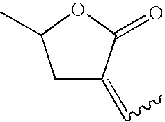
C7H10O2 126 (E,Z)-3-propylidene-5-methyl- dihydro-furan-2-one 
C8H12O2 140 (E,Z)-3-butylidene-5-methyl- dihydro-furan-2-one 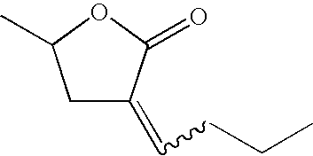
C9H14O2 154 (E,Z)-3-pentylidene-5-methyl- dihydro-furan-2-one 
C10H16O2 168 (E,Z)-3-Hexylidene-5-methyl- dihydro-furan-2-one 
C11H18O2 182 (E,Z)-3-Heptylidene-5-methyl- dihydro-furan-2-one 
C12H20O2 196 (E,Z)-3-octylidene-5-meethyl- dihydro-furan-2-one 
C13H22O2 210 (E,Z)-3-nonylidene-5-methyl- dihydro-furan-2-one 
C14H24O2 224 (E,Z)-3-decylidene-5-methyl- dihydro-furan-2-one 
C15H26O2 238 (E,Z)-3-(3,5,5-trimethylhexylidene)- 5-methyl-dihydrofuran-2-one 
C14H24O2 224 (E,Z)-3-cyclohexylmethylidene-5- methyl-dihydrofuran-2-one 
C12H18O2 194 gamma-octalactone 
C8H14O2 142 gamma-nonalactone 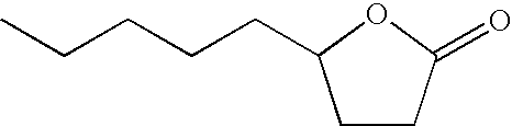
C9H18O2 156 gamma-decalactone 
C10H18O2 170 gamma-undecalactone 
C11H20O2 184 gamma-dodecalactone 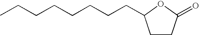
C12H22O2 198 3-hexyldihydro-furan-2-one 
C10H18O2 170 3-heptyldihydro-furan-2-one 
C11H20O2 184 cis-3-ethyl-5-methyl-dihydro-furan- 2-one 
C7H12O2 128 cis-(3-propyl-5-methyl)-dihydro- furan-2-one 
C8H14O2 142 cis-(3-butyl-5-methyl)-dihydro- furan-2-one 
C9H16O2 156 cis-(3-pentyl-5-methyl)-dihydro- furan-2-one 
C10H18O2 170 cis-(2-hexyl-5-methyl-dihydro-furan- 2-one 
C11H20O2 184 cis-3-hexyl-5-methyl-dihydro-furan- 2-one 
C12H22O2 198 cis-3-octyl-5-methyl-dihydro-furan- 2-one 
C13H24O2 212 cis-3-(3,5,5-trimeethylhexyl)-5- methyl-dihydro-furan-2-one 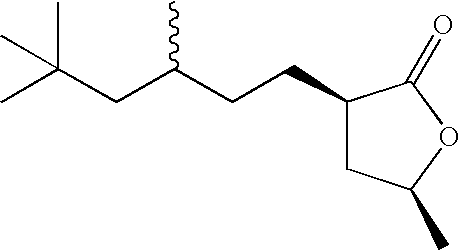
C14H26O2 226 cis-3-cyclohexylmeethyl-5-methyl- dihydro-furan-2-one 
C12H20O2 196 5-methyl-5-hexyl-dihydro-furan-2- one 
C11H20O2 184 5-methyl-5-octyl-dihydro-furan-2- one 
C13H24O2 212 Hexahydro-isobenzofuran-1-one 
C8H12O2 140 delta-decalactone 
C10H18O2 170 delta-undecalactone 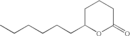
C11H20O2 184 delta-dodecalactone 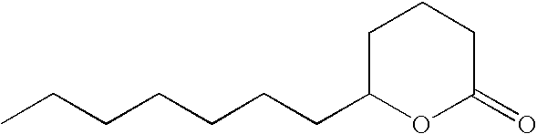
C12H22O2 198 mixture of 4-hexyl-dihydrofuran-2- one and 3-hexyl-dihydro-furan-2- one 
C10H18O2 170 - Lactone solubilizing agents generally have a kinematic viscosity of less than about 7 centistokes at 40° C. For instance, gamma-undecalactone has kinematic viscosity of 5.4 centistokes and cis-(3-hexyl-5-methyl)dihydrofuran-2-one has viscosity of 4.5 centistokes both at 40° C. Lactone solubilizing agents may be available commercially or prepared by methods as described in U.S. provisional patent application 10/910,495 (inventors being P. J. Fagan and C. J. Brandenburg), filed Aug. 3, 2004, incorporated herein by reference.
- Aryl ether solubilizing agents of the present invention further comprise aryl ethers represented by the formula R1OR2, wherein: R1 is selected from aryl hydrocarbon radicals having from 6 to 12 carbon atoms; R2 is selected from aliphatic hydrocarbon radicals having from 1 to 4 carbon atoms; and wherein said aryl ethers have a molecular weight of from about 100 to about 150 atomic mass units. Representative R1 aryl radicals in the general formula R1OR2 include phenyl, biphenyl, cumenyl, mesityl, tolyl, xylyl, naphthyl and pyridyl. Representative R2 aliphatic hydrocarbon radicals in the general formula R1OR2 include methyl, ethyl, propyl, isopropyl, butyl, isobutyl, sec-butyl and tert-butyl. Representative aromatic ether solubilizing agents include but are not limited to: methyl phenyl ether (anisole), 1,3-dimethyoxybenzene, ethyl phenyl ether and butyl phenyl ether.
- Fluoroether solubilizing agents of the present invention comprise those represented by the general formula R1OCF2CF2H, wherein R1 is selected from aliphatic and alicyclic hydrocarbon radicals having from about 5 to about 15 carbon atoms, preferably primary, linear, saturated, alkyl radicals. Representative fluoroether solubilizing agents include but are not limited to: C8H17OCF2CF2H and C6H13OCF2CF2H. It should be noted that if the refrigerant is a fluoroether, then the solubilizing agent may not be the same fluoroether.
- 1,1,1-Trifluoroalkane solubilizing agents of the present invention comprise 1,1,1-trifluoroalkanes represented by the general formula CF3R1, wherein R1 is selected from aliphatic and alicyclic hydrocarbon radicals having from about 5 to about 15 carbon atoms, preferably primary, linear, saturated, alkyl radicals. Representative 1,1,1-trifluoroalkane solubilizing agents include but are not limited to: 1,1,1-trifluorohexane and 1,1,1-trifluorododecane.
- Solubilizing agents of the present invention may be present as a single compound, or may be present as a mixture of more than one solubilizing agent. Mixtures of solubilizing agents may contain two solubilizing agents from the same class of compounds, say two lactones, or two solubilizing agents from two different classes, such as a lactone and a polyoxyalkylene glycol ether.
- In the present compositions comprising refrigerant and UV fluorescent dye, from about 0.001 weight percent to about 1.0 weight percent of the composition is UV dye, preferably from about 0.005 weight percent to about 0.5 weight percent, and most preferably from 0.01 weight percent to about 0.25 weight percent.
- Solubility of these UV fluorescent dyes in refrigerants may be poor. Therefore, methods for introducing these dyes into the refrigeration or air conditioning apparatus have been awkward, costly and time consuming. U.S. Pat. No. RE 36,951 describes a method, which utilizes a dye powder, solid pellet or slurry of dye that may be inserted into a component of the refrigeration or air conditioning apparatus. As refrigerant and lubricant are circulated through the apparatus, the dye is dissolved or dispersed and carried throughout the apparatus. Numerous other methods for introducing dye into a refrigeration or air conditioning apparatus are described in the literature.
- Ideally, the UV fluorescent dye could be dissolved in the refrigerant itself thereby not requiring any specialized method for introduction to the refrigeration or air conditioning apparatus. The present invention relates to compositions including UV fluorescent dye, which may be introduced into the system directly in the refrigerant. The inventive compositions will allow the storage and transport of dye-containing refrigerant even at low temperatures while maintaining the dye in solution.
- In the present compositions comprising refrigerant, UV fluorescent dye and solubilizing agent, from about 1 to about 50 weight percent, preferably from about 2 to about 25 weight percent, and most preferably from about 5 to about 15 weight percent of the combined composition is solubilizing agent in the refrigerant. In the compositions of the present invention the UV fluorescent dye is present in a concentration from about 0.001 weight percent to about 1.0 weight percent in the refrigerant, preferably from 0.005 weight percent to about 0.5 weight percent, and most preferably from 0.01 weight percent to about 0.25 weight percent.
- Optionally, commonly used refrigeration system additives may optionally be added, as desired, to compositions of the present invention in order to enhance performance and system stability. These additives are known within the field of refrigeration, and include, but are not limited to, anti wear agents, extreme pressure lubricants, corrosion and oxidation inhibitors, metal surface deactivators, free radical scavengers, and foam control agents,. In general, these additives are present in the inventive compositions in small amounts relative to the overall composition. Typically concentrations of from less than about 0.1 weight percent to as much as about 3 weight percent of each additive are used. These additives are selected on the basis of the individual system requirements. These additives include members of the triaryl phosphate family of EP (extreme pressure) lubricity additives, such as butylated triphenyl phosphates (BTPP), or other alkylated triaryl phosphate esters, e.g. Syn-0-Ad 8478 from Akzo Chemicals, tricrecyl phosphates and related compounds. Additionally, the metal dialkyl dithiophosphates (e.g. zinc dialkyl dithiophosphate (or ZDDP), Lubrizol 1375 and other members of this family of chemicals may be used in compositions of the present invention. Other antiwear additives include natural product oils and asymmetrical polyhydroxyl lubrication additives, such as Synergol TMS (International Lubricants). Similarly, stabilizers such as anti oxidants, free radical scavengers, and water scavengers may be employed. Compounds in this category can include, but are not limited to, butylated hydroxy toluene (BHT) and epoxides.
- Solubilizing agents such as ketones may have an objectionable odor, which can be masked by addition of an odor masking agent or fragrance. Typical examples of odor masking agents or fragrances may include Evergreen, Fresh Lemon, Cherry, Cinnamon, Peppermint, Floral or Orange Peel or sold by Intercontinental Fragrance, as well as d-limonene and pinene. Such odor masking agents may be used at concentrations of from about 0.001% to as much as about 15% by weight based on the combined weight of odor masking agent and solubilizing agent.
- The present invention further relates to a method of using the refrigerant or heat transfer fluid compositions further comprising ultraviolet fluorescent dye, and optionally, solubilizing agent, in refrigeration or air conditioning apparatus. The method comprises introducing the refrigerant or heat transfer fluid composition into the refrigeration or air conditioning apparatus. This may be done by dissolving the UV fluorescent dye in the refrigerant or heat transfer fluid composition in the presence of a solubilizing agent and introducing the combination into the apparatus. Alternatively, this may be done by combining solubilizing agent and and UV fluorescent dye and introducing said combination into refrigeration or air conditioning apparatus containing refrigerant and/or heat transfer fluid. The resulting composition is may be used in the refrigeration or air conditioning apparatus.
- The present invention further relates to a method of using the refrigerant or heat transfer fluid compositions comprising ultraviolet fluorescent dye to detect leaks. The presence of the dye in the compositions allows for detection of leaking refrigerant in the refrigeration or air conditioning apparatus. Leak detection helps to address, resolve or prevent inefficient operation of the apparatus or system or equipment failure. Leak detection also helps one contain chemicals used in the operation of the apparatus.
- The method comprises providing the composition comprising refrigerant, ultra-violet fluorescent dye as described herein, and optionally, a solubilizing agent as described herein, to refrigeration and air conditioning apparatus and employing a suitable means for detecting the UV fluorescent dye-containing refrigerant. Suitable means for detecting the dye include, but are not limited to, ultra-violet lamp, often referred to as a “black light” or “blue light”. Such ultra-violet lamps are commercially available from numerous sources specifically designed for this purpose. Once the ultra-violet fluorescent dye containing composition has been introduced to the refrigeration or air conditioning apparatus and has been allowed to circulate throughout the system, a leak can be found by shining said ultra-violet lamp on the apparatus and observing the fluorescence of the dye in the vicinity of any leak point.
- The present invention further relates to a method of using the compositions of the present invention for producing refrigeration or heat, wherein the method comprises producing refrigeration by evaporating said composition in the vicinity of a body to be cooled and thereafter condensing said composition; or producing heat by condensing the said composition in the vicinity of the body to be heated and thereafter evaporating said composition.
- Mechanical refrigeration is primarily an application of thermodynamics wherein a cooling medium, such as a refrigerant, goes through a cycle so that it can be recovered for reuse. Commonly used cycles include vapor-compression, absorption, steam-jet or steam-ejector, and air.
- Vapor-compression refrigeration systems include an evaporator, a compressor, a condenser, and an expansion device. A vapor-compression cycle re-uses refrigerant in multiple steps producing a cooling effect in one step and a heating effect in a different step. The cycle can be described simply as follows. Liquid refrigerant enters an evaporator through an expansion device, and the liquid refrigerant boils in the evaporator at a low temperature to form a gas and produce cooling. The low-pressure gas enters a compressor where the gas is compressed to raise its pressure and temperature. The higher-pressure (compressed) gaseous refrigerant then enters the condenser in which the refrigerant condenses and discharges its heat to the environment. The refrigerant returns to the expansion device through which the liquid expands from the higher-pressure level in the condenser to the low-pressure level in the evaporator, thus repeating the cycle.
- There are various types of compressors that may be used in refrigeration applications. Compressors can be generally classified as reciprocating, rotary, jet, centrifugal, scroll, screw or axial-flow, depending on the mechanical means to compress the fluid, or as positive-displacement (e.g., reciprocating, scroll or screw) or dynamic (e.g., centrifugal or jet), depending on how the mechanical elements act on the fluid to be compressed.
- Either positive displacement or dynamic compressors may be used in the present inventive process. A centrifugal type compressor is the preferred equipment for the present refrigerant compositions.
- A centrifugal compressor uses rotating elements to accelerate the refrigerant radially, and typically includes an impeller and diffuser housed in a casing. Centrifugal compressors usually take fluid in at an impeller eye, or central inlet of a circulating impeller, and accelerate it radially outward. Some static pressure rise occurs in the impeller, but most of the pressure rise occurs in the diffuser section of the casing, where velocity is converted to static pressure. Each impeller-diffuser set is a stage of the compressor. Centrifugal compressors are built with from 1 to 12 or more stages, depending on the final pressure desired and the volume of refrigerant to be handled.
- The pressure ratio, or compression ratio, of a compressor is the ratio of absolute discharge pressure to the absolute inlet pressure. Pressure delivered by a centrifugal compressor is practically constant over a relatively wide range of capacities.
- Positive displacement compressors draw vapor into a chamber, and the chamber decreases in volume to compress the vapor. After being compressed, the vapor is forced from the chamber by further decreasing the volume of the chamber to zero or nearly zero. A positive displacement compressor can build up a pressure, which is limited only by the volumetric efficiency and the strength of the parts to withstand the pressure.
- Unlike a positive displacement compressor, a centrifugal compressor depends entirely on the centrifugal force of the high-speed impeller to compress the vapor passing through the impeller. There is no positive displacement, but rather what is called dynamic-compression.
- The pressure a centrifugal compressor can develop depends on the tip speed of the impeller. Tip speed is the speed of the impeller measured at its tip and is related to the diameter of the impeller and its revolutions per minute. The capacity of the centrifugal compressor is determined by the size of the passages through the impeller. This makes the size of the compressor more dependent on the pressure required than the capacity.
- Because of its high-speed operation, a centrifugal compressor is fundamentally a high volume, low-pressure machine. A centrifugal compressor works best with a low-pressure refrigerant, such as trichlorofluoromethane (CFC-11) or 1,2,2-trichlorotrifluoroethane (CFC-113).
- Large centrifugal compressors typically operate at 3000 to 7000 revolutions per minute (rpm). Small turbine centrifugal compressors are designed for high speeds, from about 40,000 to about 70,000 (rpm), and have small impeller sizes, typically less than 0.15 meters.
- A multi-stage impeller may be used in a centrifugal compressor to improve compressor efficiency thus requiring less power in use. For a two-stage system, in operation, the discharge of the first stage impeller goes to the suction intake of a second impeller. Both impellers may operate by use of a single shaft (or axle). Each stage can build up a compression ratio of about 4 to 1; that is, the absolute discharge pressure can be four times the absolute suction pressure. An example of a two-stage centrifugal compressor system, in this case for automotive applications, is described in U.S. Pat. No. 5,065,990, incorporated herein by reference.
- The compositions of the present invention suitable for use in a refrigeration or air conditioning apparatus employing a centrifugal compressor comprise at least one of:
- C4F9OCH3 and 1,1,2,2,3-pentafluoropropane;
- C4F9OCH3 and 1,1,1,3,3-pentafluoropropane;
- C4F9OCH3 and 1,1,3-trifluoropropane;
- C4F9OCH3 and 1,3-difluoropropane;
- C4F9OCH3 and 2-(difluoromethyl)-1,1,1,2,3,3-hexafluoropropane;
- C4F9OCH3 and 1,1,2,2,3,3,4,4-octafluorobutane;
- C4F9OCH3 and 1,1,1,2,2,4-hexafluorobutane;
- C4F9OCH3 and 1,1,1,3,3-pentafluorobutane;
- C4F9OCH3 and 1,1-difluorobutane;
- C4F9OCH3 and 1,3-difluoro-2-methylpropane;
- C4F9OCH3 and 1,2-difluoro-2-methylpropane;
- C4F9OCH3 and 1,2-difluorobutane;
- C4F9OCH3 and 1,3-difluorobutane;
- C4F9OCH3 and 1,4-difluorobutane;
- C4F9OCH3 and 2,3-difluorobutane;
- C4F9OCH3 and 1,1,1,2,3,3,4,4-octafluoro-2-(trifluoromethyl)butane;
- C4F9OCH3 and 1,1,1,2,2,3,3,4,4,5,5-undecafluoropentane;
- C4F9OCH3 and 1,1,1,2,2,3,4,5,5,5-decafluoropentane;
- C4F9OCH3 and 1,1,1,2,2,3,3,5,5,5-decafluoropentane;
- C4F9OCH3 and 1,1,1,4,4,4-hexafluoro-2-(trifluoromethyl)butane;
- C4F9OCH3 and 1,1,1-trifluoropentane;
- C4F9OCH3 and 1,1,1-trifluoro-3-methylbutane;
- C4F9OCH3 and 1,1-difluoropentane;
- C4F9OCH3 and 1,2-difluoropentane;
- C4F9OCH3 and 2,2-difluoropentane;
- C4F9OCH3 and 1,1,1-trifluorohexane;
- C4F9OCH3 and 1,1,1,2,2,3,3,4,4,5,5,6,6-tridecafluorohexane;
- C4F9OCH3 and 1,1,1,2,2,5,5,5-octafluoro-4-(trifluoromethyl)pentane; and
- C4F9OCH3 and 1,1,2,2,-tetrafluorocyclobutane.
- These above-listed compositions are also suitable for use in two-stage centrifugal compressor apparatus and suitable for use in refrigeration or air conditioning apparatus employing a single slab/single pass heat exchanger:
- The compositions of the present invention may be used in stationary air-conditioning, heat pumps or mobile air-conditioning and refrigeration systems. Stationary air conditioning and heat pump applications include window, ductless, ducted, packaged terminal, chillers and commercial, including packaged rooftop. Refrigeration applications include domestic or home refrigerators and freezers, ice machines, self-contained coolers and freezers, walk-in coolers and freezers and transport refrigeration systems.
- The compositions of the present invention may additionally be used in air-conditioning, heating and refrigeration systems that employ fin and tube heat exchangers, microchannel heat exchangers and vertical or horizontal single pass tube or plate type heat exchangers.
- Conventional microchannel heat exchangers may not be ideal for the low pressure refrigerant compositions of the present invention. The low operating pressure and density result in high flow velocities and high frictional losses in all components. In these cases, the evaporator design may be modified. Rather than several microchannel slabs connected in series (with respect to the refrigerant path) a single slab/single pass heat exchanger arrangement may be used. Therefore, a preferred heat exchanger for the low pressure refrigerants of the present invention is a single slab/single pass heat exchanger.
- The compositions of the present invention are particularly useful in small turbine centrifugal compressors, which can be used in auto and window air conditioning or heat pump as well as other applications. These high efficiency miniature centrifugal compressors may be driven by an electric motor and can therefore be operated independently of the engine speed. A constant compressor speed allows the system to provide a relatively constant cooling capacity at all engine speeds. This provides an opportunity for efficiency improvements especially at higher engine speeds as compared to a conventional R-134a automobile air-conditioning system. When the cycling operation of conventional systems at high driving speeds is taken into account, the advantage of these low pressure systems becomes even greater.
- Some of the low pressure refrigerant fluids of the present invention may be suitable as drop-in replacements for CFC-113 in existing centrifugal equipment.
- The present invention relates to a process for producing refrigeration comprising evaporating the compositions of the present invention in the vicinity of a body to be cooled, and thereafter condensing said compositions.
- The present invention further relates to a process for producing heat comprising condensing the compositions of the present invention in the vicinity of a body to be heated, and thereafter evaporating said compositions.
- The present invention further relates to a process for transfer of heat from a heat source to a heat sink wherein the compositions of the present invention serve as heat transfer fluids. Said process for heat transfer comprises transferring the compositions of the present invention from a heat source to a heat sink.
- Heat transfer fluids are utilized to transfer, move or remove heat from one space, location, object or body to a different space, location, object or body by radiation, conduction, or convection. A heat transfer fluid may function as a secondary coolant by providing means of transfer for cooling (or heating) from a remote refrigeration (or heating) system. In some systems, the heat transfer fluid may remain in a constant state throughout the transfer process (i.e., not evaporate or condense). Alternatively, evaporative cooling processes may utilize heat transfer fluids as well.
- A heat source may be defined as any space, location, object or body from which it is desirable to transfer, move or remove heat. Examples of heat sources may be spaces (open or enclosed) requiring refrigeration or cooling, such as refrigerator or freezer cases in a supermarket, building spaces requiring air conditioning, or the passenger compartment of an automobile requiring air conditioning. A heat sink may be defined as any space, location, object or body capable of absorbing heat. A vapor compression refrigeration system is one example of such a heat sink.
- A vessel is charged with an initial composition at a specified temperature, and the initial vapor pressure of the composition is measured. The composition is allowed to leak from the vessel, while the temperature is held constant, until 50 weight percent of the initial composition is removed, at which time the vapor pressure of the composition remaining in the vessel is measured. The results are summarized in Table 4 below.
TABLE 4 After 50% After 50% Compounds Initial Initial Leak Leak Delta wt % A/wt % B Psia kPa Psia kPa P % C4F9OCH3/HFC-263fa (42.4° C.) 40.8/59.2 14.68 101.22 14.68 101.22 0.0% 20/80 14.43 99.49 14.24 98.18 1.3% 10/90 14.09 97.15 13.83 95.36 1.8% 1/99 13.55 93.42 13.51 93.15 0.3% 0/100 13.48 92.94 13.48 92.94 0.0% 60/40 14.45 99.63 14.20 97.91 1.7% 78/22 13.49 93.01 12.17 83.93 9.8% 100/0 7.98 55.02 7.98 55.02 0.0% C4F9OCH3/HFC-392qfe (59.0° C.) 49.3/50.7 14.70 101.35 14.70 101.35 0.0% 20/80 14.55 100.32 14.53 100.18 0.1% 10/90 14.42 99.42 14.40 99.29 0.1% 1/99 14.26 98.32 14.26 98.32 0.0% 0/100 14.24 98.18 14.24 98.18 0.0% 80/20 14.51 100.04 14.50 99.97 0.1% 90/10 14.37 99.08 14.37 99.08 0.0% 99/1 14.23 98.11 14.23 98.11 0.0% 100/0 14.22 98.04 14.22 98.04 0.0% C4F9OCH3/HFC-4-11-2sc (54.3° C.) 63.8/36.2 14.67 101.15 14.67 101.15 0.0% 40/60 14.33 98.80 14.10 97.22 1.6% 20/80 13.59 93.70 13.10 90.32 3.6% 10/90 13.03 89.84 12.63 87.08 3.1% 1/99 12.37 85.29 12.32 84.94 0.4% 0/100 12.29 84.74 12.29 84.74 0.0% 80/20 14.39 99.22 14.24 98.18 1.0% 90/10 13.72 94.60 13.40 92.39 2.3% 99/1 12.37 85.29 12.28 84.67 0.7% 100/0 12.15 83.77 12.15 83.77 0.0% C4F9OCH3/HFC-5-12-3m (59.6° C.) 91.0/9.0 14.68 101.22 14.68 101.22 0.0% 99/1 14.55 100.32 14.54 100.25 0.1% 100/0 14.50 99.97 14.50 99.97 0.0% 60/40 13.78 95.01 13.29 91.63 3.6% 40/60 12.71 87.63 11.50 79.29 9.5% 39/61 12.65 87.22 11.40 78.60 9.9% C4F9OCH3/HFC-C354cc (50° C.) 7.2/92.8 14.71 101.42 14.71 101.42 0.0% 1/99 14.70 101.35 14.70 101.35 0.0% 0/100 14.70 101.35 14.70 101.35 0.0% 20/80 14.66 101.08 14.65 101.01 0.1% 40/60 14.38 99.15 14.29 98.53 0.6% 60/40 13.77 94.94 13.50 93.08 2.0% 80/20 12.61 86.94 12.19 84.05 3.3% 90/10 11.70 80.67 11.35 78.26 3.0% 99/1 10.61 73.15 10.56 72.81 0.5% 100/0 10.47 72.19 10.47 72.19 0.0% - The results show the difference in vapor pressure between the original composition and the composition remaining after 50 weight percent has been removed is less then about 10 percent for compositions of the present invention. This indicates compositions of the present invention are azeotropic or near-azeotrope. Where an azeotrope is present, the data show compositions of the present invention have an initial vapor pressure higher than the vapor pressure of either pure component.
- Tip speed can be estimated by making some fundamental relationships for refrigeration equipment that use centrifugal compressors. The torque an impeller ideally imparts to a gas is defined as
T=m*(v 2 *r 2 −v 1 *r 1) Equation 1
where - T=torque, N*m
- m=mass rate of flow, kg/s
- V2=tangential velocity of refrigerant leaving impeller (tip speed), m/s
- r2=radius of exit impeller, m
- v1=tangential velocity of refrigerant entering impeller, m/s
- r1=radius of inlet of impeller, m
- Assuming the refrigerant enters the impeller in an essentially radial direction, the tangential component of the velocity v1=0, therefore
T=m*v 2 *r 2 Equation 2 - The power required at the shaft is the product of the torque and the rotative speed
P=T*w Equation 3
where - P=power, W
- w=rotative speed, rez/s
- therefore,
P=T*w=m*v 2 *r 2 *w Equation 4 - At low refrigerant flow rates, the tip speed of the impeller and the tangential velocity of the refrigerant are nearly identical; therefore
r 2 *w=v 2 Equation 5
and
P=m*v 2 *v 2 Equation 6 - Another expression for ideal power is the product of the mass rate of flow and the isentropic work of compression,
P=m*H i*(1000 J/kJ) Equation 7
where - Hi=Difference in enthalpy of the refrigerant from a saturated vapor at the evaporating conditions to saturated condensing conditions, kJ/kg.
- Combining the two expressions Equation 6 and 7 produces,
v 2 *v 2=1000*H i Equation 8 - Although Equation 8 is based on some fundamental assumptions, it provides a good estimate of the tip speed of the impeller and provides an important way to compare tip speeds of refrigerants.
- Table 6 below shows theoretical tip speeds that are calculated for 1,2,2-trichlorotrifluoroethane (CFC-113) and compositions of the present invention. The conditions assumed for this comparison are:
Evaporator temperature 40.0° F. (4.4° C.) Condenser temperature 110.0° F. (43.3° C.) Liquid subcool temperature 10.0° F. (5.5° C.) Return gas temperature 75.0° F. (23.8° C.) Compressor efficiency is 70% - These are typical conditions under which small turbine centrifugal compressors perform.
TABLE 6 Refrigerant wt % Hi Hi*0.7 Hi*0.7 V2 V2 rel Composition C4F9OCH3 wt % B Btu/lb Btu/lb KJ/Kg m/s to CFC-113 CFC-113 10.92 7.6 17.8 133.3 n/a C4F9OCH3 plus (B): HFC-263fa 40.8 59.2 14.33 10.0 23.3 152.7 115% HFC-392qfe 49.3 50.7 16.24 11.4 26.4 162.6 122% HFC-4-11-2sc 63.8 36.2 15.69 11.0 25.5 159.8 120% HFC-5-12-3m 91.0 9.0 13.45 9.4 21.9 148.0 111% HFC-c354cc 7.2 92.8 15.13 10.6 24.6 157.0 118% - The example shows that compounds of the present invention have tip speeds within about +/−20 percent of CFC-113 and would be effective replacements for CFC-113 with minimal compressor design changes.
-
Evaporator temperature 40.0° F. (4.4° C.) Condenser temperature 110.0° F. (43.3° C.) Subcool temperature 10.0° F. (5.5° C.) Return gas temperature 75.0° F. (23.8° C.) Compressor efficiency is 70% -
TABLE 7 Compr Compr Evap Evap Cond Cond Disch Disch Refrigerant wt % wt % Pres Pres Pres Pres Temp Temp Capacity Capacity Composition C4F9OCH3 B (Psia) (kPa) (Psia) (kPa) (F.) (C.) COP (Btu/min) (kW) CFC-113 2.7 19 12.8 88 156.3 69.1 4.18 14.8 0.26 C4F9OCH3 plus (B): HFC-263fa 40.8 59.2 3.2 22 15.2 105 159.5 70.8 4.20 20.3 0.35 HFC-392qfe 49.3 50.7 1.6 11 8.5 59 152.9 67.2 4.19 10.9 0.19 HFC-4-11-2sc 63.8 36.2 2.0 14 10.1 70 138.0 58.9 4.03 12.5 0.22 HFC-5-12-3m 91.0 9.0 1.5 10 8.2 57 132.1 55.6 3.94 9.5 0.17 HFC-c354cc 7.2 92.8 2.4 16 11.0 76 153.6 67.6 4.19 14.7 0.26
Data show the compositions of the present invention have evaporator and condenser pressures similar to CFC-113. Some compositions also have higher capacity or energy efficiency (COP) than CFC-113.
Claims (42)
1. (canceled)
2. (canceled)
3. (canceled)
4. (canceled)
5. (canceled)
6. (canceled)
7. (canceled)
8. (canceled)
9. (canceled)
10. (canceled)
11. (canceled)
12. (canceled)
13. (canceled)
14. (canceled)
15. (canceled)
16. (canceled)
17. (canceled)
18. (canceled)
19. A refrigerant or heat transfer fluid composition comprising C4F9OCH3 and at least one hydrofluorocarbon selected from the group consisting of:
1,1,2,2,3-pentafluoropropane;
1,1,1,3,3-pentafluoropropane;
1,1,3-trifluoropropane;
1,3-difluoropropane;
2-(difluoromethyl)-1,1,1,2,3,3-hexafluoropropane;
1,1,2,2,3,3,4,4-octafluorobutane;
1,1,1,2,2,4-hexafluorobutane;
1,1-difluorobutane;
1,3-difluoro-2-methylpropane;
1,2-difluoro-2-methylpropane;
1,2-difluorobutane;
1,3-difluorobutane;
1,4-difluorobutane;
2,3-difluorobutane;
1,1,1,2,3,3,4,4-octafluoro-2-(trifluoromethyl)butane;
1,1,1,2,2,3,3,4,4,5,5-undecafluoropentane;
1,1,1,2,2,3,4,5,5,5-decafluoropentane;
1,1,1,2,2,3,3,5,5,5-decafluoropentane;
1,1,1,4,4,4-hexafluoro-2-(trifluoromethyl)butane;
1,1,1-trifluoropentane;
1,1,1-trifluoro-3-methylbutane;
1,1-difluoropentane;
1,2-difluoropentane;
2,2-difluoropentane;
1,1,1-trifluorohexane;
1,1,1,2,2,3,3,4,4,5,5,6,6-tridecafluorohexane;
1,1,1,2,2,5,5,5-octafluoro-4-(trifluoromethyl)pentane; and
1,1,2,2,-tetrafluorocyclobutane.
20. The refrigerant or heat transfer fluid composition of claim 19 , wherein the composition comprises a composition selected from the group consisting of:
C4F9OCH3 and 1,1,2,2,3-pentafluoropropane;
C4F9OCH3 and 1,1,1,3,3-pentafluoropropane;
C4F9OCH3 and 1,1,3-trifluoropropane;
C4F9OCH3 and 1,3-difluoropropane;
C4F9OCH3 and 2-(difluoromethyl)-1,1,1,2,3,3-hexafluoropropane;
C4F9OCH3 and 1,1,2,2,3,3,4,4-octafluorobutane;
C4F9OCH3 and 1,1,1,2,2,4-hexafluorobutane;
C4F9OCH3 and 1,1-difluorobutane;
C4F9OCH3 and 1,3-difluoro-2-methylpropane;
C4F9OCH3 and 1,2-difluoro-2-methylpropane;
C4F9OCH3 and 1,2-difluorobutane;
C4F9OCH3 and 1,3-difluorobutane;
C4F9OCH3 and 1,4-difluorobutane;
C4F9OCH3 and 2,3-difluorobutane;
C4F9OCH3 and 1,1,1,2,3,3,4,4-octafluoro-2-(trifluoromethyl)butane;
C4F9OCH3 and 1,1,1,2,2,3,3,4,4,5,5-undecafluoropentane;
C4F9OCH3 and 1,1,1,2,2,3,4,5,5,5-decafluoropentane;
C4F9OCH3 and 1,1,1,2,2,3,3,5,5,5-decafluoropentane;
C4F9OCH3 and 1,1,1,4,4,4-hexafluoro-2-(trifluoromethyl)butane;
C4F9OCH3 and 1,1,1-trifluoropentane;
C4F9OCH3 and 1,1,1-trifluoro-3-methylbutane;
C4F9OCH3 and 1,1-difluoropentane;
C4F9OCH3 and 1,2-difluoropentane;
C4F9OCH3 and 2,2-difluoropentane;
C4F9OCH3 and 1,1,1-trifluorohexane;
C4F9OCH3 and 1,1,1,2,2,3,3,4,4,5,5,6,6-tridecafluorohexane;
C4F9OCH3 and 1,1,1,2,2,5,5,5-octafluoro-4-(trifluoromethyl)pentane; and
C4F9OCH3 and 1,1,2,2,-tetrafluorocyclobutane.
21. The refrigerant or heat transfer fluid composition of claim 19 , wherein the composition comprises an azeotropic or near-azeotropic composition composition selected from the group consisting of:
about 1 to about 78 weight percent C4F9OCH3 and about 99 to about 22 weight percent 1,1,3-trifluoropropane;
about 1 to about 99 weight percent C4F9OCH3 and about 99 to about 1 weight percent 1,3-difluorobutane;
about 1 to about 99 weight percent C4F9OCH3 and about 99 to about 1 weight percent 2,2-difluoropentane;
about 39 to about 99 weight percent C4F9OCH3 and about 61 to about 1 weight percent 1,1,1-trifluorohexane; and
about 1 to about 99 weight percent C4F9OCH3 and about 99 to about 1 weight percent 1,1,2,2-tetrafluorocyclobutane.
22. The refrigerant or heat transfer fluid composition of claim 19 , wherein the composition comprises an azeotropic composition selected from the group consisting of:
40.8 weight percent C4F9OCH3 and 59.2 weight percent 1,1,3-trifluoropropane having a vapor pressure of about 14.7 psia (101 kPa) at a temperature of about 42.4° C.;
49.3 weight percent C4F9OCH3 and 50.7 weight percent 1,3-difluorobutane having a vapor pressure of about 14.7 psia (101 kPa) at a temperature of about 59.0° C.;
63.8 weight percent C4F9OCH3 and 36.2 weight percent 2,2-difluoropentane having a vapor pressure of about 14.7 psia (101 kPa) at a temperature of about 54.3° C.;
91.0 weight percent C4F9OCH3 and 9.0 weight percent 1,1,1-trifluorohexane having a vapor pressure of about 14.7 psia (101 kPa) at a temperature of about 59.6° C.; and
7.2 weight percent C4F9OCH3 and 92.8 weight percent 1,1,2,2-tetrafluorocyclobutane having a vapor pressure of about 14.7 psia (101 kPa) at a temperature of about 50.0° C.
23. A process for producing refrigeration, said process comprising evaporating the composition of claim 19 in the vicinity of a body to be cooled, and thereafter condensing said composition.
24. A process for producing heat, said process comprising condensing the composition of claim 19 in the vicinity of a body to be heated, and thereafter evaporating said composition.
25. A method of using the compositions of claim 19 for heat transfer, said method comprising transferring said composition from a heat source to a heat sink.
26. The composition of claim 19 , further comprising at least one ultra-violet fluorescent dye selected from the group consisting of naphthalimides, perylenes, coumarins, anthracenes, phenanthracenes, xanthenes, thioxanthenes, naphthoxanthenes, fluoresceins, derivatives of said dye and combinations thereof.
27. The composition of claim 26 , further comprising at least one solubilizing agent selected from the group consisting of hydrocarbons, dimethylether, polyoxyalkylene glycol ethers, amides, ketones, nitriles, chlorocarbons, esters, lactones, aryl ethers, hydrofluoroethers, and 1,1,1-trifluoroalkanes; and wherein the refrigerant and solubilizing agent are not the same compound.
28. The composition of claim 27 , wherein said solubilizing agent is selected from the group consisting of:

a) polyoxyalkylene glycol ethers represented by the formula R1[(OR2)xOR3]y, wherein: x is an integer from 1 to 3; y is an integer from 1 to 4; R1 is selected from hydrogen and aliphatic hydrocarbon radicals having 1 to 6 carbon atoms and y bonding sites; R2 is selected from aliphatic hydrocarbylene radicals having from 2 to 4 carbon atoms; R3 is selected from hydrogen, and aliphatic and alicyclic hydrocarbon radicals having from 1 to 6 carbon atoms; at least one of R1 and R3 is selected from said hydrocarbon radicals; and wherein said polyoxyalkylene glycol ethers have a molecular weight of from about 100 to about 300 atomic mass units;
b) amides represented by the formulae R1CONR2R3 and cyclo-[R4CON(R5)—], wherein R1, R2, R3 and R5 are independently selected from aliphatic and alicyclic hydrocarbon radicals having from 1 to 12 carbon atoms, and at most one aromatic radical having from 6 to 12 carbon atoms; R4 is selected from aliphatic hydrocarbylene radicals having from 3 to 12 carbon atoms; and wherein said amides have a molecular weight of from about 100 to about 300 atomic mass units;
c) ketones represented by the formula R1COR2, wherein R1 and R2 are independently selected from aliphatic, alicyclic and aryl hydrocarbon radicals having from 1 to 12 carbon atoms, and wherein said ketones have a molecular weight of from about 70 to about 300 atomic mass units;
d) nitriles represented by the formula R1CN, wherein R1 is selected from aliphatic, alicyclic or aryl hydrocarbon radicals having from 5 to 12 carbon atoms, and wherein said nitriles have a molecular weight of from about 90 to about 200 atomic mass units;
e) chlorocarbons represented by the formula RClx, wherein; x is selected from the integers 1 or 2; R is selected from aliphatic and alicyclic hydrocarbon radicals having from 1 to 12 carbon atoms; and wherein said chlorocarbons have a molecular weight of from about 100 to about 200 atomic mass units;
f) aryl ethers represented by the formula R1OR2, wherein: R1 is selected from aryl hydrocarbon radicals having from 6 to 12 carbon atoms; R2 is selected from aliphatic hydrocarbon radicals having from 1 to 4 carbon atoms; and wherein said aryl ethers have a molecular weight of from about 100 to about 150 atomic mass units;
g) 1,1 1-trifluoroalkanes represented by the formula CF3R1, wherein R1 is selected from aliphatic and alicyclic hydrocarbon radicals having from about 5 to about 15 carbon atoms;
i) hydrofluoroethers represented by the formula R1OCF2CF2H, wherein R1 is selected from aliphatic and alicyclic hydrocarbon radicals having from about 5 to about 15 carbon atoms; and
j) lactones represented by structures [B], [C], and [D]:
wherein, R1 through R8 are independently selected from hydrogen, linear, branched, cyclic, bicyclic, saturated and unsaturated hydrocarbyl radicals; and the molecular weight is from about 100 to about 300 atomic mass units; and
k) esters represented by the general formula R1CO2R2, wherein R1 and R2 are independently selected from linear and cyclic, saturated and unsaturated, alkyl and aryl radicals; and wherein said esters have a molecular weight of from about 80 to about 550 atomic mass units.
29. A method for using the composition of claim 28 , said method comprising: introducing the composition into a compression refrigeration or air conditioning apparatus by (i) dissolving the ultraviolet fluorescent dye in the refrigerant composition of heat transfer fluid in the presence of the solubilizing agent, and introducing the combination into said compression refrigeration or air conditioning apparatus or (ii), combining solubilizing agent and UV fluorescent dye and introducing said combination into refrigeration or air conditioning apparatus containing refrigerant and/or heat transfer fluid.
30. A method for detecting leaks in a compression refrigeration or air conditioning apparatus, said method comprising providing a compression refrigeration apparatus or air-conditioning apparatus, introducing the composition of claim 8 into said apparatus, and providing a suitable means for detecting said composition at a leak point or in the vicinity of said apparatus.
31. The method of claim 23 , wherein the refrigerant or heat transfer composition further comprises at least one ultra-violet fluorescent dye selected from the group consisting of naphthalimides, perylenes, coumarins, anthracenes, phenanthracenes, xanthenes, thioxanthenes, naphthoxanthenes, fluoresceins, derivatives of said dye and combinations thereof.
32. The method of claim 24 , wherein the refrigerant or heat transfer composition further comprises at least one ultra-violet fluorescent dye selected from the group consisting of naphthalimides, perylenes, coumarins, anthracenes, phenanthracenes, xanthenes, thioxanthenes, naphthoxanthenes, fluoresceins, derivatives of said dye and combinations thereof.
33. The composition of claim 19 further comprising a thermal stabilizer or odor masking agent.
34. The composition of claim 33 wherein said thermal stabilizer is nitromethane.
35. The method of claim 23 , wherein said method further comprises producting cooling in a refrigeration or air-conditioning apparatus employing a multi-stage centrifugal compressor.
36. The method of claim 35 wherein said multi-stage compressor is a two-stage compressor.
37. The method of claim 24 , wherein said method further comprises producing cooling in a refrigeration or air-conditioning apparatus employing a multi-stage centrifugal compressor.
38. The method of claim 37 wherein said multi-stage compressor is a two-stage compressor.
39. The composition of claim 34 wherein said water scavenger is an ortho ester.
40. A process to produce cooling comprising compressing a composition of claim 19 in a mini-centrifugal compressor powered by an engine exhaust gas driven turbine; condensing said composition; and thereafter evaporating said composition in the vicinity of a body to be cooled.
41. The process of claim 23 , wherein the refrigerant or heat transfer composition is compressed in a mini-centrifugal compressor powered by a ratioed gear drive assembly with a ratioed belt drive; prior to the said condensing of said composition.
42. A method for replacing CFC-113 in existing refrigeration apparatus or air-conditioning apparatus, said method comprising providing a composition of claim 19 as the replacement.
Priority Applications (2)
| Application Number | Priority Date | Filing Date | Title |
|---|---|---|---|
| US11/703,878 US7354529B2 (en) | 2004-01-14 | 2007-02-08 | 1,1,1,2,2,3,3,4,4-nonafluro-4-methoxybutane refrigerant compositions comprising hydrofluorocarbon, and uses thereof |
| US12/026,771 US20080127659A1 (en) | 2004-01-14 | 2008-02-06 | 1,1,1,2,2,3,3,4,4-nonafluoro-4-methoxybutane refrigerant compositions comprising hydrofluorocarbon, and uses thereof |
Applications Claiming Priority (7)
| Application Number | Priority Date | Filing Date | Title |
|---|---|---|---|
| US53681904P | 2004-01-14 | 2004-01-14 | |
| US53745304P | 2004-01-15 | 2004-01-15 | |
| US54997804P | 2004-03-04 | 2004-03-04 | |
| US57503704P | 2004-05-26 | 2004-05-26 | |
| US58478504P | 2004-06-29 | 2004-06-29 | |
| US11/014,438 US20050151112A1 (en) | 2004-01-14 | 2004-12-16 | 1,1,1,2,2,3,3,4,4-Nonafluoro-4-methoxybutane refrigerant compositions comprising hydrofluorocarbon, and uses thereof |
| US11/703,878 US7354529B2 (en) | 2004-01-14 | 2007-02-08 | 1,1,1,2,2,3,3,4,4-nonafluro-4-methoxybutane refrigerant compositions comprising hydrofluorocarbon, and uses thereof |
Related Parent Applications (1)
| Application Number | Title | Priority Date | Filing Date |
|---|---|---|---|
| US11/014,438 Division US20050151112A1 (en) | 2004-01-14 | 2004-12-16 | 1,1,1,2,2,3,3,4,4-Nonafluoro-4-methoxybutane refrigerant compositions comprising hydrofluorocarbon, and uses thereof |
Related Child Applications (1)
| Application Number | Title | Priority Date | Filing Date |
|---|---|---|---|
| US12/026,771 Division US20080127659A1 (en) | 2004-01-14 | 2008-02-06 | 1,1,1,2,2,3,3,4,4-nonafluoro-4-methoxybutane refrigerant compositions comprising hydrofluorocarbon, and uses thereof |
Publications (2)
| Publication Number | Publication Date |
|---|---|
| US20070194271A1 true US20070194271A1 (en) | 2007-08-23 |
| US7354529B2 US7354529B2 (en) | 2008-04-08 |
Family
ID=34743984
Family Applications (3)
| Application Number | Title | Priority Date | Filing Date |
|---|---|---|---|
| US11/014,438 Abandoned US20050151112A1 (en) | 2004-01-14 | 2004-12-16 | 1,1,1,2,2,3,3,4,4-Nonafluoro-4-methoxybutane refrigerant compositions comprising hydrofluorocarbon, and uses thereof |
| US11/703,878 Expired - Fee Related US7354529B2 (en) | 2004-01-14 | 2007-02-08 | 1,1,1,2,2,3,3,4,4-nonafluro-4-methoxybutane refrigerant compositions comprising hydrofluorocarbon, and uses thereof |
| US12/026,771 Abandoned US20080127659A1 (en) | 2004-01-14 | 2008-02-06 | 1,1,1,2,2,3,3,4,4-nonafluoro-4-methoxybutane refrigerant compositions comprising hydrofluorocarbon, and uses thereof |
Family Applications Before (1)
| Application Number | Title | Priority Date | Filing Date |
|---|---|---|---|
| US11/014,438 Abandoned US20050151112A1 (en) | 2004-01-14 | 2004-12-16 | 1,1,1,2,2,3,3,4,4-Nonafluoro-4-methoxybutane refrigerant compositions comprising hydrofluorocarbon, and uses thereof |
Family Applications After (1)
| Application Number | Title | Priority Date | Filing Date |
|---|---|---|---|
| US12/026,771 Abandoned US20080127659A1 (en) | 2004-01-14 | 2008-02-06 | 1,1,1,2,2,3,3,4,4-nonafluoro-4-methoxybutane refrigerant compositions comprising hydrofluorocarbon, and uses thereof |
Country Status (1)
| Country | Link |
|---|---|
| US (3) | US20050151112A1 (en) |
Families Citing this family (1)
| Publication number | Priority date | Publication date | Assignee | Title |
|---|---|---|---|---|
| US20060242985A1 (en) | 2005-03-04 | 2006-11-02 | Leck Thomas J | Refrigeration/air-conditioning apparatus powered by an engine exhaust gas driven turbine |
Citations (12)
| Publication number | Priority date | Publication date | Assignee | Title |
|---|---|---|---|---|
| US4987154A (en) * | 1986-01-14 | 1991-01-22 | Alliance Pharmaceutical Corp. | Biocompatible, stable and concentrated fluorocarbon emulsions for contrast enhancement and oxygen transport in internal animal use |
| US5580906A (en) * | 1995-05-19 | 1996-12-03 | E. I. Du Pont De Nemours And Company | Ternary azeotropic compositions |
| US5672293A (en) * | 1994-03-11 | 1997-09-30 | E. I. Du Pont De Nemours And Company | Hydrofluorocarbon compositions |
| US5827812A (en) * | 1995-05-16 | 1998-10-27 | Minnesota Mining And Manufacturing Company | Azeotrope-like compositions and their use |
| US6127430A (en) * | 1998-12-16 | 2000-10-03 | 3M Innovative Properties Company | Microemulsions containing water and hydrofluroethers |
| US6159917A (en) * | 1998-12-16 | 2000-12-12 | 3M Innovative Properties Company | Dry cleaning compositions containing hydrofluoroether |
| US6183663B1 (en) * | 1998-10-09 | 2001-02-06 | Bright Solutions, Inc. | Leak detection dye delivery system |
| US6423673B1 (en) * | 2001-09-07 | 2002-07-23 | 3M Innovation Properties Company | Azeotrope-like compositions and their use |
| US6576153B2 (en) * | 1995-09-14 | 2003-06-10 | Alliedsignal Inc. | Hydrofluorocarbon refrigerants for use in centrifugal chillers |
| US6660709B1 (en) * | 1998-12-12 | 2003-12-09 | Solvay (Societe Anonyme) | Compositions comprising 1,1,1,3,3-pentafluorobutane and use of these compositions |
| US20040031948A1 (en) * | 2000-11-15 | 2004-02-19 | Solvay Fluor Und Derivate Gmbh | Method of transferring heat using a working fluid containing 1,1,1,3,3-pentafluorobutane as refrigerant or heat transfer medium |
| US20040226303A1 (en) * | 2001-08-23 | 2004-11-18 | Solvay Pharmaceuticals Gmbh | Use of 1,1,1,3,3-pentafluorobutane as a refrigerant in a turbocompressor cooling system |
Family Cites Families (4)
| Publication number | Priority date | Publication date | Assignee | Title |
|---|---|---|---|---|
| US5411192A (en) * | 1993-07-01 | 1995-05-02 | Xiao; Ji | Tote bag and table apparatus |
| WO1996040834A1 (en) | 1995-06-07 | 1996-12-19 | E.I. Du Pont De Nemours And Company | Refrigerants based on hydrofluoroether of fluoroether |
| JP3131403B2 (en) * | 1997-04-07 | 2001-01-31 | 日本サーボ株式会社 | Stepping motor |
| JP2002226839A (en) | 2001-01-29 | 2002-08-14 | Kaneko Kagaku:Kk | Refrigerant |
-
2004
- 2004-12-16 US US11/014,438 patent/US20050151112A1/en not_active Abandoned
-
2007
- 2007-02-08 US US11/703,878 patent/US7354529B2/en not_active Expired - Fee Related
-
2008
- 2008-02-06 US US12/026,771 patent/US20080127659A1/en not_active Abandoned
Patent Citations (12)
| Publication number | Priority date | Publication date | Assignee | Title |
|---|---|---|---|---|
| US4987154A (en) * | 1986-01-14 | 1991-01-22 | Alliance Pharmaceutical Corp. | Biocompatible, stable and concentrated fluorocarbon emulsions for contrast enhancement and oxygen transport in internal animal use |
| US5672293A (en) * | 1994-03-11 | 1997-09-30 | E. I. Du Pont De Nemours And Company | Hydrofluorocarbon compositions |
| US5827812A (en) * | 1995-05-16 | 1998-10-27 | Minnesota Mining And Manufacturing Company | Azeotrope-like compositions and their use |
| US5580906A (en) * | 1995-05-19 | 1996-12-03 | E. I. Du Pont De Nemours And Company | Ternary azeotropic compositions |
| US6576153B2 (en) * | 1995-09-14 | 2003-06-10 | Alliedsignal Inc. | Hydrofluorocarbon refrigerants for use in centrifugal chillers |
| US6183663B1 (en) * | 1998-10-09 | 2001-02-06 | Bright Solutions, Inc. | Leak detection dye delivery system |
| US6660709B1 (en) * | 1998-12-12 | 2003-12-09 | Solvay (Societe Anonyme) | Compositions comprising 1,1,1,3,3-pentafluorobutane and use of these compositions |
| US6127430A (en) * | 1998-12-16 | 2000-10-03 | 3M Innovative Properties Company | Microemulsions containing water and hydrofluroethers |
| US6159917A (en) * | 1998-12-16 | 2000-12-12 | 3M Innovative Properties Company | Dry cleaning compositions containing hydrofluoroether |
| US20040031948A1 (en) * | 2000-11-15 | 2004-02-19 | Solvay Fluor Und Derivate Gmbh | Method of transferring heat using a working fluid containing 1,1,1,3,3-pentafluorobutane as refrigerant or heat transfer medium |
| US20040226303A1 (en) * | 2001-08-23 | 2004-11-18 | Solvay Pharmaceuticals Gmbh | Use of 1,1,1,3,3-pentafluorobutane as a refrigerant in a turbocompressor cooling system |
| US6423673B1 (en) * | 2001-09-07 | 2002-07-23 | 3M Innovation Properties Company | Azeotrope-like compositions and their use |
Also Published As
| Publication number | Publication date |
|---|---|
| US7354529B2 (en) | 2008-04-08 |
| US20080127659A1 (en) | 2008-06-05 |
| US20050151112A1 (en) | 2005-07-14 |
Similar Documents
| Publication | Publication Date | Title |
|---|---|---|
| US7276177B2 (en) | Hydrofluorocarbon refrigerant compositions and uses thereof | |
| US7094356B2 (en) | 1,1,1,2,2,4,5,5,5-nonafluoro-4-(trifluoromethyl)-3-pentanone refrigerant compositions and uses thereof | |
| US7479239B2 (en) | 1,1,1,2,2,4,5,5,5-nonafluoro-4-(trifluoromethyl)-3-pentanone compositions comprising a hydrofluorocarbon and uses thereof | |
| US7252780B2 (en) | 1,1,1,2,2,4,5,5,5-nonafluoro-4-(trifluoromethyl)-3-pentanone refrigerant and heat transfer compositions comprising a fluoroether | |
| US7422699B2 (en) | 1,1,1,3,3-pentafluorobutane refrigerant or heat transfer fluid compositions comprising hydrofluorocarbon and uses thereof | |
| US7338616B2 (en) | 1,1,1,2,2,4,5,5,5-Nonafluoro-4-(trifluoromethyl)-3-pentanone refrigerant compositions comprising a hydrocarbon and uses thereof | |
| US20050151110A1 (en) | Fluoroether refrigerant compositions and uses thereof | |
| US7351351B2 (en) | 1,1,1,2,2,3,3,4,4-Nonafluoro-4-methoxybutane refrigerant compositions comprising functionalized organic compounds and uses thereof | |
| US7351352B2 (en) | 1,1,1,2,2,3,3,4,4-Nonafluoro-4-methoxybutane refrigerant compositions comprising a fluoroether and uses thereof | |
| WO2005067558A2 (en) | Refrigerant compositions comprising 1-ethoxy-1,1,2,2,3,3,4,4-nonafluorobutane and a hydrofluorocarbon and uses thereof | |
| US7208099B2 (en) | Refrigerant compositions comprising 1-ethoxy-1,1,2,2,3,3,4,4,4-nonafluorobutane and a hydrofluorocarbon and uses thereof | |
| US7201855B2 (en) | 1,1,1,3,3-pentafluorobutane refrigerant compositions comprising fluoroether and uses thereof | |
| WO2005067555A2 (en) | 1,1,1,3,3-pentafluorobutane refrigerant or heat transfer fluid compositions comprising hydrofluorocarbon and uses thereof | |
| US7208100B2 (en) | 1-ethoxy-1,1,2,2,3,3,4,4,4-nonafluorobutane refrigerant compositions comprising a fluoroether and uses thereof | |
| US7354529B2 (en) | 1,1,1,2,2,3,3,4,4-nonafluro-4-methoxybutane refrigerant compositions comprising hydrofluorocarbon, and uses thereof | |
| EP1723211A2 (en) | 1,1,1,2,2,3,3,4,4-nonafluoro-4-methoxybutane refrigerant compositions comprising hydrofluorocarbon, and uses thereof |
Legal Events
| Date | Code | Title | Description |
|---|---|---|---|
| FPAY | Fee payment |
Year of fee payment: 4 |
|
| REMI | Maintenance fee reminder mailed | ||
| LAPS | Lapse for failure to pay maintenance fees | ||
| STCH | Information on status: patent discontinuation |
Free format text: PATENT EXPIRED DUE TO NONPAYMENT OF MAINTENANCE FEES UNDER 37 CFR 1.362 |
|
| FP | Lapsed due to failure to pay maintenance fee |
Effective date: 20160408 |