US20080040887A1 - Friction hinge for electronic apparatus - Google Patents
Friction hinge for electronic apparatus Download PDFInfo
- Publication number
- US20080040887A1 US20080040887A1 US11/505,248 US50524806A US2008040887A1 US 20080040887 A1 US20080040887 A1 US 20080040887A1 US 50524806 A US50524806 A US 50524806A US 2008040887 A1 US2008040887 A1 US 2008040887A1
- Authority
- US
- United States
- Prior art keywords
- hinge assembly
- pin
- receive
- base
- cam
- Prior art date
- Legal status (The legal status is an assumption and is not a legal conclusion. Google has not performed a legal analysis and makes no representation as to the accuracy of the status listed.)
- Abandoned
Links
Images


Classifications
-
- E—FIXED CONSTRUCTIONS
- E05—LOCKS; KEYS; WINDOW OR DOOR FITTINGS; SAFES
- E05D—HINGES OR SUSPENSION DEVICES FOR DOORS, WINDOWS OR WINGS
- E05D11/00—Additional features or accessories of hinges
- E05D11/08—Friction devices between relatively-movable hinge parts
- E05D11/087—Friction devices between relatively-movable hinge parts with substantially axial friction, e.g. friction disks
-
- B—PERFORMING OPERATIONS; TRANSPORTING
- B60—VEHICLES IN GENERAL
- B60R—VEHICLES, VEHICLE FITTINGS, OR VEHICLE PARTS, NOT OTHERWISE PROVIDED FOR
- B60R11/00—Arrangements for holding or mounting articles, not otherwise provided for
- B60R11/02—Arrangements for holding or mounting articles, not otherwise provided for for radio sets, television sets, telephones, or the like; Arrangement of controls thereof
-
- E—FIXED CONSTRUCTIONS
- E05—LOCKS; KEYS; WINDOW OR DOOR FITTINGS; SAFES
- E05D—HINGES OR SUSPENSION DEVICES FOR DOORS, WINDOWS OR WINGS
- E05D11/00—Additional features or accessories of hinges
- E05D11/0081—Additional features or accessories of hinges for transmitting energy, e.g. electrical cable routing
-
- B—PERFORMING OPERATIONS; TRANSPORTING
- B60—VEHICLES IN GENERAL
- B60R—VEHICLES, VEHICLE FITTINGS, OR VEHICLE PARTS, NOT OTHERWISE PROVIDED FOR
- B60R11/00—Arrangements for holding or mounting articles, not otherwise provided for
- B60R2011/0042—Arrangements for holding or mounting articles, not otherwise provided for characterised by mounting means
- B60R2011/008—Adjustable or movable supports
- B60R2011/0082—Adjustable or movable supports collapsible, e.g. for storing after use
-
- B—PERFORMING OPERATIONS; TRANSPORTING
- B60—VEHICLES IN GENERAL
- B60R—VEHICLES, VEHICLE FITTINGS, OR VEHICLE PARTS, NOT OTHERWISE PROVIDED FOR
- B60R11/00—Arrangements for holding or mounting articles, not otherwise provided for
- B60R2011/0042—Arrangements for holding or mounting articles, not otherwise provided for characterised by mounting means
- B60R2011/008—Adjustable or movable supports
- B60R2011/0085—Adjustable or movable supports with adjustment by rotation in their operational position
-
- E—FIXED CONSTRUCTIONS
- E05—LOCKS; KEYS; WINDOW OR DOOR FITTINGS; SAFES
- E05Y—INDEXING SCHEME RELATING TO HINGES OR OTHER SUSPENSION DEVICES FOR DOORS, WINDOWS OR WINGS AND DEVICES FOR MOVING WINGS INTO OPEN OR CLOSED POSITION, CHECKS FOR WINGS AND WING FITTINGS NOT OTHERWISE PROVIDED FOR, CONCERNED WITH THE FUNCTIONING OF THE WING
- E05Y2600/00—Mounting or coupling arrangements for elements provided for in this subclass
- E05Y2600/60—Mounting or coupling members; Accessories therefore
- E05Y2600/634—Spacers
- E05Y2600/636—Washers
-
- E—FIXED CONSTRUCTIONS
- E05—LOCKS; KEYS; WINDOW OR DOOR FITTINGS; SAFES
- E05Y—INDEXING SCHEME RELATING TO HINGES OR OTHER SUSPENSION DEVICES FOR DOORS, WINDOWS OR WINGS AND DEVICES FOR MOVING WINGS INTO OPEN OR CLOSED POSITION, CHECKS FOR WINGS AND WING FITTINGS NOT OTHERWISE PROVIDED FOR, CONCERNED WITH THE FUNCTIONING OF THE WING
- E05Y2800/00—Details, accessories and auxiliary operations not otherwise provided for
- E05Y2800/20—Combinations of elements
- E05Y2800/21—Combinations of elements of identical elements, e.g. of identical compression springs
-
- E—FIXED CONSTRUCTIONS
- E05—LOCKS; KEYS; WINDOW OR DOOR FITTINGS; SAFES
- E05Y—INDEXING SCHEME RELATING TO HINGES OR OTHER SUSPENSION DEVICES FOR DOORS, WINDOWS OR WINGS AND DEVICES FOR MOVING WINGS INTO OPEN OR CLOSED POSITION, CHECKS FOR WINGS AND WING FITTINGS NOT OTHERWISE PROVIDED FOR, CONCERNED WITH THE FUNCTIONING OF THE WING
- E05Y2800/00—Details, accessories and auxiliary operations not otherwise provided for
- E05Y2800/20—Combinations of elements
- E05Y2800/244—Combinations of elements arranged in serial relationship
-
- E—FIXED CONSTRUCTIONS
- E05—LOCKS; KEYS; WINDOW OR DOOR FITTINGS; SAFES
- E05Y—INDEXING SCHEME RELATING TO HINGES OR OTHER SUSPENSION DEVICES FOR DOORS, WINDOWS OR WINGS AND DEVICES FOR MOVING WINGS INTO OPEN OR CLOSED POSITION, CHECKS FOR WINGS AND WING FITTINGS NOT OTHERWISE PROVIDED FOR, CONCERNED WITH THE FUNCTIONING OF THE WING
- E05Y2900/00—Application of doors, windows, wings or fittings thereof
- E05Y2900/60—Application of doors, windows, wings or fittings thereof for other use
- E05Y2900/606—Application of doors, windows, wings or fittings thereof for other use for electronic devices
Definitions
- This invention relates generally to a friction hinge assembly for mounting a component to a surface.
- the invention relates to a hinge assembly for displaying and adjusting the degree of the tilt of a video display screen that is mounted within the passenger compartment of a vehicle.
- video display screens have been used in automobiles, recreational vehicles, buses, boats, airplanes, trains, and the like, for providing entertainment and information to the passengers.
- video display screens are typically connected to a video playback device such as a digital video disc (DVD) player or a video cassette recorder (VCR) or electronic gaming systems.
- DVD digital video disc
- VCR video cassette recorder
- Such screens are typically mounted to the ceiling of the passenger compartment of a vehicle and can be flipped downward when a passenger desires to view the screen or flipped up for convenient storage.
- a number of mounting systems have been proposed to allow a video display screen to be viewed by passengers when in use and hidden when not in use.
- these video display screens are mounted to the ceiling of the passenger compartment of a vehicle and are movable between a generally horizontal storage position, which is flush against the vehicle ceiling, to a generally vertical viewing position, which is typically approximately 90 degrees from the storage position.
- the present invention provides for an improved hinge assembly for mounting and displaying a video display screen to a surface, and more particularly to the ceiling of a vehicle.
- the hinge assembly allows for the pivotal attachment of a video display screen to a surface, preferably the ceiling of a vehicle, using a friction hinge.
- the hinge assembly provides a constant holding torque in either direction between the storage position and the deployed position of the video display screen.
- the hinge assembly incorporates at least one resilient member or disc spring into which the rotational shaft is inserted.
- the resilient member is located between a stationary member of the hinge assembly and at least one moveable part of the hinge assembly and functions to prevent the stationary parts and moveable parts from lock-up during rotational movement.
- a cam is equipped with at least one lobe and is used to produce a reciprocating action when engaged or contacted with another part of the hinge assembly.
- the hinge assembly is equipped with detent stops that allow for repeatable soft stops.
- the video display screen can be supported and pivoted by two hinge assemblies located on either side of the video display screen.
- the two hinge assemblies may be connected if desired by a shared pin or a connecting bar.
- the hinge assembly is equipped with a torsion spring that is adapted to provide a separate force on the hinge assembly to allow for easy accessibility when the user of the video display screen desires to use the video display screen.
- the torsion spring can be activated to allow the video display screen to pivot downward from the horizontal storage position.
- the hinge assembly incorporates a hollow pin adapted to allow at least one wire to run through the pin.
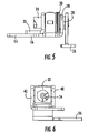
- FIG. 1 is a side elevational view of a hinge assembly in accordance with one embodiment of the present invention
- FIG. 2 is a front elevational view of the hinge assembly of FIG. 1 ;
- FIG. 3 is a side elevational view of the hinge assembly of FIG. 1 ;
- FIG. 4 is a perspective view of a hinge assembly in accordance with one embodiment of the present invention.
- FIG. 5 is a side elevational view of the hinge assembly of FIG. 4 ;
- FIG. 6 is a front elevational view of the hinge assembly of FIG. 4 ;
- FIG. 7 is a top plan view of the hinge assembly of FIG. 4 ;
- FIG. 8 is a cross-sectional view of the hinge assembly of FIG. 4 along lines 8 - 8 of FIG. 7 ;
- FIG. 9 is a perspective view of a hinge assembly in accordance with one embodiment of the present invention.
- FIG. 9 a is a perspective view of an alternative embodiment of the hinge assembly of FIG. 9 ;
- FIG. 10 is a top plan view of the hinge assembly of FIG. 9 ;
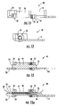
- FIG. 11 is a side elevational view of the hinge assembly of FIG. 9 ;
- FIG. 12 is a front elevational view of the hinge assembly of FIG. 9 ;
- FIG. 13 is a cross-sectional view of the hinge assembly of FIG. 9 along lines 13 - 13 of FIG. 10 ;
- FIG. 13 a is a cross-sectional view of the hinge assembly of FIG. 9 a;
- FIG. 14 is a perspective view of a hinge assembly in accordance with one embodiment of the present invention.
- FIG. 15 is a top plan view of the hinge assembly of FIG. 14 ;
- FIG. 16 is a side elevational view of the hinge assembly of FIG. 14 ;
- FIG. 17 is a front elevational view of the hinge assembly of FIG. 14 ;
- FIG. 18 is a cross-sectional view of the hinge assembly of FIG. 14 along lines 18 - 18 of FIG. 15 ;
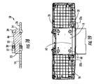
- FIG. 19 is a bottom plan view of a hinge assembly in accordance with one embodiment of the present invention shown in an installed configuration
- FIG. 19 a is a bottom plan view of an alternative embodiment of the hinge assembly configuration shown in FIG. 19 ;
- FIG. 20A is a detail view taken from FIG. 19 ;
- FIG. 20B is a detail view taken from FIG. 19 ;
- FIG. 21 is a perspective view of a hinge assembly in accordance with one embodiment of the present invention.
- FIG. 22 is a side elevational view of the hinge assembly of FIG. 21 .
- the present invention is directed to a friction hinge assembly 12 for pivotably mounting a video display screen 10 (shown in FIG. 19 ) to a surface.
- video display screen 10 means the video display screen 10 , the housing for the video display screen 10 and any other structure that is used to frame the video display screen 10 .
- the hinge assembly 12 preferably pivotably attaches a video display screen 10 to the ceiling of a vehicle, the hinge assembly 12 can be used for any movable display unit mounted on many surfaces, such as an interior surface of any type of vehicle, a storage housing unit that is attached to the ceiling of a vehicle, a recess located in the ceiling of a vehicle or the underside of a kitchen cabinet.
- the ceiling of the passenger compartment of a vehicle is used herein as a representative example of a surface that the hinge assembly 12 can be mounted to and a video display screen 10 shall be used as a representative example of a component that can be mounted to the ceiling of a vehicle by the hinge assembly 12 .
- a video display screen 10 shall be used as a representative example of a component that can be mounted to the ceiling of a vehicle by the hinge assembly 12 .
- the present invention is suitable for pivotably coupling any object to any surface.
- a friction hinge assembly 12 is used to pivotably attach a video display screen 10 to the ceiling of a vehicle.
- the hinge assembly 12 is preferably constructed of metal, although other material can be utilized. With the use of the hinge assembly 12 , the video display screen 10 can be pivoted downward from a generally horizontal storage position on the ceiling of a vehicle to any suitable desired angled position, preferably within about 90 degrees from the storage position. In the storage position, the video display screen 10 will preferably be generally parallel to or in planar alignment with or recessed in the ceiling of the vehicle.
- the hinge assembly 12 allows the video display screen 10 to be moved between a storage position and a deployed position. The hinge assembly 12 also frictionally maintains the video display screen 10 at a desired position anywhere between the storage position and the deployed position.
- the hinge assembly 12 comprises a base 14 at least a portion of which can be attached to the ceiling of a vehicle.
- the base 14 is a stationary component that will not pivot when the moveable members of the hinge assembly 12 rotate and the video display screen 10 unit is pivoted.
- the base 14 is preferably L-shaped with a long arm 16 that is mounted to the ceiling and a short arm 18 with a generally circular opening that allows for the attachment of the short arm 18 of the base 14 to the remainder of the hinge assembly 12 .
- the long arm 16 can be connected to the ceiling in any number of ways, including, but not limited to, through the use of at least one fastener or welding.
- the long arm 16 can include at least one opening 20 to receive the fastener.
- the base 14 can be designed in one of many different ways depending on the stationary surface that the base 14 will be mounted to.
- the hinge assembly 12 also comprises a pin 22 with a first end 23 and a second end 24 .
- the first end 23 of the pin 22 is inserted through at least the opening of the short arm 18 of the base 14 .
- the first end 23 of the pin 22 and second end 24 of the pin 22 extend in either direction of the opening of the short arm 18 of the base 14 .
- the pin 22 allows for the attachment of the other components of the hinge assembly 12 to the base 14 and specifically the short arm 18 .
- the hinge assembly 12 also comprises a video display bracket 26 that can be connected to a video display screen 10 .
- the bracket 26 contains at least one opening to allow the first end of the pin to be inserted and thereby attach the bracket to the remainder of the hinge assembly 12 .
- the bracket 26 may also have a second opening 27 to allow the bracket to be connected to the video display screen 10 .
- the bracket 26 can be connected to the video display screen 10 in any number of ways, including, but not limited to, through the use of at least one fastener or by welding. Additionally, through the use of a desired fastener, the bracket 26 may be constructed so that the video display screen 10 can be detached or reattached as desired. Such feature can be useful for maintenance, removal or replacement of the video display screen 10 .
- the bracket 26 will pivot relative to the base 14 thereby allowing the video display screen 10 to pivot relative to the ceiling.
- the bracket 26 can be designed in one of many different ways depending on the size and shape of the video display screen 10 or other object that will be mounted to a stationary surface.
- the bracket 26 and the short arm 18 of the base 14 can be separated by at least one spacer 28 to allow for a smoother rotation of the hinge assembly 12 .
- the spacer 28 would be inserted onto the pin 22 before the bracket 26 .
- the spacer 28 can be formed as a part of the bracket 26 or the spacer 28 can be formed as a separate component.
- a fixed or removable bushing 29 may be used to secure the bracket 26 to the pin 22 .
- the hinge assembly 12 also comprises at least one resilient washer 30 for applying axial compressive resilience to the hinge assembly 12 .
- the resilient washer 30 can by a Belleville washer, spring washer, curved washer or tension washer.
- the resilient washer 30 has a generally circular shaped opening and is placed on the pin 22 through the opening.
- the resilient washer 30 is preferably disposed between the stationary short arm 18 of the base 14 and at least one movable part of the hinge assembly 12 .
- the resilient washer 30 prevents the friction that is created during rotation of the hinge assembly 12 from locking the movable and stationary parts together during torque adjustment.
- the use of at least one resilient washer 30 will function place a load axially along the pin to limit axial movement of the components of the hinge assembly 12 along the pin 22 during rotational movement of the moveable components of the hinge assembly 12 around the pin 22 .
- the resilient washer 30 will maintain constant torque regardless of the position of the hinge assembly 12 .
- the use of at least one resilient washer 30 can function to prevent malfunction and undue wear and tear of the hinge assembly 12 .
- multiple resilient washers 30 are used to provide adequate flexibility by producing a higher torque or a hinge assembly 12 with higher loading capacity.
- the hinge assembly can also incorporate a support member 32 that is inserted onto the pin 22 adjacent to the resilient washer 30 .
- the support member 32 has a generally circular shaped opening and is placed on the pin 22 through the opening.
- the support member 32 is preferably generally the same diameter as the resilient washer 30 . If a support member 32 is utilized and in position on the pin 22 it serves to compress the resilient washer 30 .
- the hinge assembly 12 can also include, if desired, a cam 34 that is preferably placed on the pin 22 closest to the first end 23 of the pin 22 .
- the cam 34 functions to, among other things, perform a reciprocating action when the hinge is moved, such as activating or deactivating a switch. Accordingly in one embodiment of the invention, when the movable parts of the hinge assembly 12 rotate, the video display screen 10 pivots downward from the storage position and the cam 34 serves to activate a switch to automatically turn the video display screen 10 on. Alternatively, when the movable parts of the hinge assembly 12 rotate back to their initial position, the video display screen 10 pivots upward to the storage position and the cam 34 serves to deactivate a switch to automatically turn the video display screen 10 off.
- the cam 34 can be placed on the pin 22 first, then the support member 32 , then at least one resilient washer 30 , then the short arm 18 of the base 14 , then a spacer 28 and finally the bracket 26 .
- the hinge assembly 12 can also include a second cam 36 .
- the second cam 36 has an opening and is also placed on the pin 22 through the opening.
- the second cam 36 also rotates, thereby allowing the hinge assembly 12 to perform at least one additional function.
- the second cam 36 may be formed with at least one lobe 38 and the base 14 of the hinge assembly 12 can incorporate at least one flange.
- the base 14 can incorporate two flanges, a first flange 40 and a second flange 42 .
- the first flange 40 and second flange 42 will not rotate relative to the pin 22 . Accordingly, if a movable second cam 36 is incorporated on the pin 22 , the first flange 40 and second flange 42 can assist the second cam 36 with the accomplishment of at least one additional function.
- the first flange 40 and/or second flange 42 can incorporate at least one detent 44 that is of the appropriate size, shape and location to accept at least one lobe 38 from the second cam 36 .
- the detent 44 can be an opening, as demonstrated in FIG. 4 , a groove, catch or lever that temporarily locks the movement of the second cam 36 .
- the second cam 36 incorporates at least one lobe 38 , when the lobe 38 rotates relative to the pin 22 with the remainder of the moveable parts of the hinge assembly 12 , the lobe 38 will temporarily snap into the detent 44 on the first flange 40 or second flange 42 and the entire hinge assembly 12 will stop rotating.
- the detent 44 and lobe 38 may be positioned such that when the movably parts of the hinge assembly 12 are rotated, the video display screen 10 can be easily lowered to certain predetermined ideal viewing positions.
- the second cam 36 is equipped with two lobes and the first flange 40 and the second flange 42 each incorporate one detent 44 .
- both lobes will snap into their respective detents simultaneously.
- the lobe 38 and detent 44 can serve to prohibit the hinge assembly 12 from over rotating beyond a position that is 90 degrees from the horizontal storage position.
- the base 14 and specifically the long arm 16 of the base 14 may also be equipped with at least one detent that accepts at least one lobe from the second cam 36 .
- the base 14 can be constructed such that the short arm 18 is formed with an extension 45 that serves as a flange.
- an angled support member 33 can also be used to support the pin 22 if a second cam 36 is present. As demonstrated in FIG. 4 , the angled support member 33 is fixed to the base 14 .
- a pin 22 may be incorporated that varies in diameter. As demonstrated in FIGS. 13 and 18 , the diameter of the pin 22 is preferably longer in the center 46 and shorter at the first end 23 and second end 24 . Such an arrangement allows for proper attachment of the remainder of the hinge assembly 12 to the pin 22 .
- the pin 22 is hollow and has a first opening 54 at the first end 23 of the pin 22 and a second opening 56 at the second end 24 of the pin 22 . If the pin 22 is hollow, at least one wire 58 can be inserted through one of the openings and out the other opening in the pin 22 . Accordingly, in this embodiment of the invention, any necessary wire that is used for the video display screen 10 can be run through the pin 22 .
- the present invention can be constructed so that the hinge direction is either left handed or right handed.
- the base 14 and the bracket 26 can be arranged on the pin 22 such that the video display screen 10 swings up and down to the left of the base 14 .
- the base 14 and the bracket 26 can be arranged on the pin 22 such that the video display screen 10 swings up and down to the right of the base 14 .
- the right handed hinge assembly 48 or left handed hinge assembly 50 is achieved by the orientation of the hinge assembly 12 components on the pin 22 .
- both a right handed hinge assembly 48 and a left handed hinge assembly 50 may be utilized together as demonstrated in FIGS. 19 , 20 A, and 20 B.
- the base 14 from the right handed hinge assembly 48 and the base from the left handed hinge assembly 50 are attached to a stationary surface and are located on either side of the video display screen 10 .
- the video display screen 10 is attached to the right handed hinge assembly 48 at its bracket 26 and the left handed hinge assembly 50 at its bracket 26 .
- the right handed hinge assembly 48 and left handed hinge assembly 50 work in unison to pivot the video display screen 10 relative the stationary surface.
- the right handed hinge assembly 48 and a left handed hinge assembly 50 may be attached together by a common element 60 , such as a bar, stamping or plate that spans between the right handed hinge assembly 48 and a left handed hinge assembly 50 .
- a common element 60 such as a bar, stamping or plate that spans between the right handed hinge assembly 48 and a left handed hinge assembly 50 .
- the right handed hinge assembly 48 and a left handed hinge assembly 50 may share a common pin 22 .
- the right handed hinge assembly 48 and left handed hinge assembly 50 work in unison to assure that the video display screen 10 is properly aligned relative to the stationary surface.
- a common element 60 with the right handed hinge assembly 48 and left handed hinge assembly 50 can ensure that the video display screen 10 is moved to its proper storage position and deploy position.
- the use of a common element 60 will allow for precise closure of the video display screen 10 if the video display screen 10 is stored within a recess located in the ceiling of vehicle. For example when stored within such a recess, at least one gap will be created between the video display screen 10 and at least one edge of the recess within the ceiling.
- the use of a connection between right handed hinge assembly 48 and left handed hinge assembly 50 can ensure that the gap is consistently spaced from one end to the other.
- the hinge assembly 12 includes a torsion spring 52 that is used as means to overcome the torque of the friction hinge assembly 12 . Accordingly, if the torsion spring 52 is used, the torsion spring 52 will provide a separate force on the hinge assembly that will allow for easy accessibility when the user of the video display screen 10 desires to use the video display screen 10 .
- the torsion spring 52 when the torsion spring 52 is activated the video display screen 10 will pivot downward, preferably at an angle of approximately 20 degrees from the horizontal storage position.
- the user may activate the torsion spring 52 in any one of a number of ways, including but not limited to, unhooking a latch or pressing a release button.
- the video display screen 10 can automatically pivot downward approximately 20 degrees, then the user can manually position the video display screen 10 through the use of the friction hinge assembly 12 to the desired deployed location. Other means for biasing display screen 10 to pivot downward may also be used.
Abstract
A hinge assembly mounts a video display screen to a surface, and more particularly to the passenger compartment of a vehicle. The hinge assembly allows for the pivotal attachment of a video display screen to a surface, preferably the ceiling of a vehicle, using a friction hinge. The hinge assembly may include a resilient washer that is attached to the hinge assembly on a pin. The resilient washer functions to limit axial movement of the hinge assembly along the pin and is adapted to prevent the hinge assembly from locking-up during rotational movement of the video display screen.
Description
- This invention relates generally to a friction hinge assembly for mounting a component to a surface. In particular, the invention relates to a hinge assembly for displaying and adjusting the degree of the tilt of a video display screen that is mounted within the passenger compartment of a vehicle.
- As vehicles have evolved, entertainment devices have been added to make traveling more enjoyable. For example, video display screens have been used in automobiles, recreational vehicles, buses, boats, airplanes, trains, and the like, for providing entertainment and information to the passengers. Such video display screens are typically connected to a video playback device such as a digital video disc (DVD) player or a video cassette recorder (VCR) or electronic gaming systems. Such screens are typically mounted to the ceiling of the passenger compartment of a vehicle and can be flipped downward when a passenger desires to view the screen or flipped up for convenient storage.
- A number of mounting systems have been proposed to allow a video display screen to be viewed by passengers when in use and hidden when not in use. Commonly, these video display screens are mounted to the ceiling of the passenger compartment of a vehicle and are movable between a generally horizontal storage position, which is flush against the vehicle ceiling, to a generally vertical viewing position, which is typically approximately 90 degrees from the storage position.
- The current systems suffer from certain drawbacks and limitations. Accordingly, a need exists for an improved hinge assembly that adequately supports the video display screen at a viewing position, will not easily wear after prolonged use, is relatively inexpensive to manufacture, will maintain consistent torque, is relatively compact, will not lock-up during rotational movement of the video display screen, provides adequate support to hold the video display screen to the stationary surface and solves other problems associated with the existing systems.
- The present invention provides for an improved hinge assembly for mounting and displaying a video display screen to a surface, and more particularly to the ceiling of a vehicle. The hinge assembly allows for the pivotal attachment of a video display screen to a surface, preferably the ceiling of a vehicle, using a friction hinge.
- In one embodiment of the present invention, the hinge assembly provides a constant holding torque in either direction between the storage position and the deployed position of the video display screen.
- In one embodiment of the present invention, the hinge assembly incorporates at least one resilient member or disc spring into which the rotational shaft is inserted. The resilient member is located between a stationary member of the hinge assembly and at least one moveable part of the hinge assembly and functions to prevent the stationary parts and moveable parts from lock-up during rotational movement.
- In one embodiment of the present invention, a cam is equipped with at least one lobe and is used to produce a reciprocating action when engaged or contacted with another part of the hinge assembly.
- In one embodiment of the present invention, the hinge assembly is equipped with detent stops that allow for repeatable soft stops.
- In one embodiment of the present invention, the video display screen can be supported and pivoted by two hinge assemblies located on either side of the video display screen. The two hinge assemblies may be connected if desired by a shared pin or a connecting bar.
- In one embodiment of the present invention, the hinge assembly is equipped with a torsion spring that is adapted to provide a separate force on the hinge assembly to allow for easy accessibility when the user of the video display screen desires to use the video display screen. The torsion spring can be activated to allow the video display screen to pivot downward from the horizontal storage position.
- In one embodiment of the present invention the hinge assembly incorporates a hollow pin adapted to allow at least one wire to run through the pin.
-
FIG. 1 is a side elevational view of a hinge assembly in accordance with one embodiment of the present invention; -
FIG. 2 is a front elevational view of the hinge assembly ofFIG. 1 ; -
FIG. 3 is a side elevational view of the hinge assembly ofFIG. 1 ; -
FIG. 4 is a perspective view of a hinge assembly in accordance with one embodiment of the present invention; -
FIG. 5 is a side elevational view of the hinge assembly ofFIG. 4 ; -
FIG. 6 is a front elevational view of the hinge assembly ofFIG. 4 ; -
FIG. 7 is a top plan view of the hinge assembly ofFIG. 4 ; -
FIG. 8 is a cross-sectional view of the hinge assembly ofFIG. 4 along lines 8-8 ofFIG. 7 ; -
FIG. 9 is a perspective view of a hinge assembly in accordance with one embodiment of the present invention; -
FIG. 9 a is a perspective view of an alternative embodiment of the hinge assembly ofFIG. 9 ; -
FIG. 10 is a top plan view of the hinge assembly ofFIG. 9 ; -
FIG. 11 is a side elevational view of the hinge assembly ofFIG. 9 ; -
FIG. 12 is a front elevational view of the hinge assembly ofFIG. 9 ; -
FIG. 13 is a cross-sectional view of the hinge assembly ofFIG. 9 along lines 13-13 ofFIG. 10 ; -
FIG. 13 a is a cross-sectional view of the hinge assembly ofFIG. 9 a; -
FIG. 14 is a perspective view of a hinge assembly in accordance with one embodiment of the present invention; -
FIG. 15 is a top plan view of the hinge assembly ofFIG. 14 ; -
FIG. 16 is a side elevational view of the hinge assembly ofFIG. 14 ; -
FIG. 17 is a front elevational view of the hinge assembly ofFIG. 14 ; -
FIG. 18 is a cross-sectional view of the hinge assembly ofFIG. 14 along lines 18-18 ofFIG. 15 ; -
FIG. 19 is a bottom plan view of a hinge assembly in accordance with one embodiment of the present invention shown in an installed configuration; -
FIG. 19 a is a bottom plan view of an alternative embodiment of the hinge assembly configuration shown inFIG. 19 ; -
FIG. 20A is a detail view taken fromFIG. 19 ; -
FIG. 20B is a detail view taken fromFIG. 19 ; -
FIG. 21 is a perspective view of a hinge assembly in accordance with one embodiment of the present invention; and -
FIG. 22 is a side elevational view of the hinge assembly ofFIG. 21 . - The present invention is directed to a
friction hinge assembly 12 for pivotably mounting a video display screen 10 (shown inFIG. 19 ) to a surface. As used herein,video display screen 10 means thevideo display screen 10, the housing for thevideo display screen 10 and any other structure that is used to frame thevideo display screen 10. Although thehinge assembly 12 preferably pivotably attaches avideo display screen 10 to the ceiling of a vehicle, thehinge assembly 12 can be used for any movable display unit mounted on many surfaces, such as an interior surface of any type of vehicle, a storage housing unit that is attached to the ceiling of a vehicle, a recess located in the ceiling of a vehicle or the underside of a kitchen cabinet. For clarity, the ceiling of the passenger compartment of a vehicle is used herein as a representative example of a surface that thehinge assembly 12 can be mounted to and avideo display screen 10 shall be used as a representative example of a component that can be mounted to the ceiling of a vehicle by thehinge assembly 12. One skilled in the art will understand that the present invention is suitable for pivotably coupling any object to any surface. - According to the present invention, a
friction hinge assembly 12 is used to pivotably attach avideo display screen 10 to the ceiling of a vehicle. Thehinge assembly 12 is preferably constructed of metal, although other material can be utilized. With the use of thehinge assembly 12, thevideo display screen 10 can be pivoted downward from a generally horizontal storage position on the ceiling of a vehicle to any suitable desired angled position, preferably within about 90 degrees from the storage position. In the storage position, thevideo display screen 10 will preferably be generally parallel to or in planar alignment with or recessed in the ceiling of the vehicle. Thehinge assembly 12 allows thevideo display screen 10 to be moved between a storage position and a deployed position. Thehinge assembly 12 also frictionally maintains thevideo display screen 10 at a desired position anywhere between the storage position and the deployed position. - Referring now to the drawings, the
hinge assembly 12 comprises a base 14 at least a portion of which can be attached to the ceiling of a vehicle. Thebase 14 is a stationary component that will not pivot when the moveable members of thehinge assembly 12 rotate and thevideo display screen 10 unit is pivoted. Thebase 14 is preferably L-shaped with along arm 16 that is mounted to the ceiling and ashort arm 18 with a generally circular opening that allows for the attachment of theshort arm 18 of the base 14 to the remainder of thehinge assembly 12. Thelong arm 16 can be connected to the ceiling in any number of ways, including, but not limited to, through the use of at least one fastener or welding. If a fastener is used to connect the base to the ceiling, then thelong arm 16 can include at least oneopening 20 to receive the fastener. As demonstrated inFIGS. 1 , 4, 9, 14, and 21, thebase 14 can be designed in one of many different ways depending on the stationary surface that the base 14 will be mounted to. - The
hinge assembly 12 also comprises apin 22 with afirst end 23 and asecond end 24. Thefirst end 23 of thepin 22 is inserted through at least the opening of theshort arm 18 of thebase 14. Thefirst end 23 of thepin 22 andsecond end 24 of thepin 22 extend in either direction of the opening of theshort arm 18 of thebase 14. Thepin 22 allows for the attachment of the other components of thehinge assembly 12 to thebase 14 and specifically theshort arm 18. - The
hinge assembly 12 also comprises avideo display bracket 26 that can be connected to avideo display screen 10. Thebracket 26 contains at least one opening to allow the first end of the pin to be inserted and thereby attach the bracket to the remainder of thehinge assembly 12. Thebracket 26 may also have asecond opening 27 to allow the bracket to be connected to thevideo display screen 10. Thebracket 26 can be connected to thevideo display screen 10 in any number of ways, including, but not limited to, through the use of at least one fastener or by welding. Additionally, through the use of a desired fastener, thebracket 26 may be constructed so that thevideo display screen 10 can be detached or reattached as desired. Such feature can be useful for maintenance, removal or replacement of thevideo display screen 10. When thehinge assembly 12 is complete, thebracket 26 will pivot relative to the base 14 thereby allowing thevideo display screen 10 to pivot relative to the ceiling. As demonstrated inFIGS. 1 , 4, 9, 14, and 21 thebracket 26 can be designed in one of many different ways depending on the size and shape of thevideo display screen 10 or other object that will be mounted to a stationary surface. - In one embodiment of the present invention, the
bracket 26 and theshort arm 18 of the base 14 can be separated by at least onespacer 28 to allow for a smoother rotation of thehinge assembly 12. In such embodiment, if theshort arm 18 of thebase 14 is already attached to thepin 22, thespacer 28 would be inserted onto thepin 22 before thebracket 26. Thespacer 28 can be formed as a part of thebracket 26 or thespacer 28 can be formed as a separate component. - As shown in
FIG. 9 , in one embodiment of the present invention, a fixed orremovable bushing 29 may be used to secure thebracket 26 to thepin 22. - The
hinge assembly 12 also comprises at least oneresilient washer 30 for applying axial compressive resilience to thehinge assembly 12. For instance, theresilient washer 30 can by a Belleville washer, spring washer, curved washer or tension washer. Theresilient washer 30 has a generally circular shaped opening and is placed on thepin 22 through the opening. Theresilient washer 30 is preferably disposed between the stationaryshort arm 18 of thebase 14 and at least one movable part of thehinge assembly 12. Theresilient washer 30 prevents the friction that is created during rotation of thehinge assembly 12 from locking the movable and stationary parts together during torque adjustment. Furthermore, the use of at least oneresilient washer 30 will function place a load axially along the pin to limit axial movement of the components of thehinge assembly 12 along thepin 22 during rotational movement of the moveable components of thehinge assembly 12 around thepin 22. Unlike springs or other similar types of devices, theresilient washer 30 will maintain constant torque regardless of the position of thehinge assembly 12. Accordingly, the use of at least oneresilient washer 30 can function to prevent malfunction and undue wear and tear of thehinge assembly 12. In one embodiment of the present invention, multipleresilient washers 30 are used to provide adequate flexibility by producing a higher torque or ahinge assembly 12 with higher loading capacity. - The hinge assembly can also incorporate a
support member 32 that is inserted onto thepin 22 adjacent to theresilient washer 30. Thesupport member 32 has a generally circular shaped opening and is placed on thepin 22 through the opening. Thesupport member 32 is preferably generally the same diameter as theresilient washer 30. If asupport member 32 is utilized and in position on thepin 22 it serves to compress theresilient washer 30. - The
hinge assembly 12 can also include, if desired, acam 34 that is preferably placed on thepin 22 closest to thefirst end 23 of thepin 22. Thecam 34 functions to, among other things, perform a reciprocating action when the hinge is moved, such as activating or deactivating a switch. Accordingly in one embodiment of the invention, when the movable parts of thehinge assembly 12 rotate, thevideo display screen 10 pivots downward from the storage position and thecam 34 serves to activate a switch to automatically turn thevideo display screen 10 on. Alternatively, when the movable parts of thehinge assembly 12 rotate back to their initial position, thevideo display screen 10 pivots upward to the storage position and thecam 34 serves to deactivate a switch to automatically turn thevideo display screen 10 off. - For clarity in describing the function and placement of each component of the
hinge assembly 12, the above-identified representative example of placement ofhinge assembly 12 components on thepin 22 has been used. One skilled in the art will understand that the present invention can be assembled in numerous different ways and the components can be inserted through an end of thepin 22 in different order than has been described herein. For example, thecam 34 can be placed on thepin 22 first, then thesupport member 32, then at least oneresilient washer 30, then theshort arm 18 of thebase 14, then aspacer 28 and finally thebracket 26. - In one embodiment of the present invention, the
hinge assembly 12 can also include asecond cam 36. Thesecond cam 36 has an opening and is also placed on thepin 22 through the opening. When the movably parts of thehinge assembly 12 rotate on thepin 22 relative to thebase 14, thesecond cam 36 also rotates, thereby allowing thehinge assembly 12 to perform at least one additional function. For example, thesecond cam 36 may be formed with at least onelobe 38 and thebase 14 of thehinge assembly 12 can incorporate at least one flange. As shown inFIG. 4 , thebase 14 can incorporate two flanges, afirst flange 40 and asecond flange 42. By their location on thebase 14 of thehinge assembly 12, thefirst flange 40 andsecond flange 42 will not rotate relative to thepin 22. Accordingly, if a movablesecond cam 36 is incorporated on thepin 22, thefirst flange 40 andsecond flange 42 can assist thesecond cam 36 with the accomplishment of at least one additional function. For example, thefirst flange 40 and/orsecond flange 42 can incorporate at least onedetent 44 that is of the appropriate size, shape and location to accept at least onelobe 38 from thesecond cam 36. Thedetent 44 can be an opening, as demonstrated inFIG. 4 , a groove, catch or lever that temporarily locks the movement of thesecond cam 36. - If the
second cam 36 incorporates at least onelobe 38, when thelobe 38 rotates relative to thepin 22 with the remainder of the moveable parts of thehinge assembly 12, thelobe 38 will temporarily snap into thedetent 44 on thefirst flange 40 orsecond flange 42 and theentire hinge assembly 12 will stop rotating. This feature allows for repeatable soft stops. Accordingly, thedetent 44 andlobe 38 may be positioned such that when the movably parts of thehinge assembly 12 are rotated, thevideo display screen 10 can be easily lowered to certain predetermined ideal viewing positions. In one embodiment of the present invention, thesecond cam 36 is equipped with two lobes and thefirst flange 40 and thesecond flange 42 each incorporate onedetent 44. In this embodiment, both lobes will snap into their respective detents simultaneously. Alternatively, thelobe 38 anddetent 44 can serve to prohibit thehinge assembly 12 from over rotating beyond a position that is 90 degrees from the horizontal storage position. Thebase 14 and specifically thelong arm 16 of thebase 14, may also be equipped with at least one detent that accepts at least one lobe from thesecond cam 36. Furthermore, as demonstrated inFIGS. 9 and 14 , thebase 14 can be constructed such that theshort arm 18 is formed with anextension 45 that serves as a flange. - In one embodiment of the present invention, an
angled support member 33 can also be used to support thepin 22 if asecond cam 36 is present. As demonstrated inFIG. 4 , theangled support member 33 is fixed to thebase 14. - In one embodiment of the present invention, as shown in
FIGS. 13 and 18 , apin 22 may be incorporated that varies in diameter. As demonstrated inFIGS. 13 and 18 , the diameter of thepin 22 is preferably longer in thecenter 46 and shorter at thefirst end 23 andsecond end 24. Such an arrangement allows for proper attachment of the remainder of thehinge assembly 12 to thepin 22. - In one embodiment of the present invention, as shown in
FIG. 9 a andFIG. 13 a, thepin 22 is hollow and has afirst opening 54 at thefirst end 23 of thepin 22 and asecond opening 56 at thesecond end 24 of thepin 22. If thepin 22 is hollow, at least onewire 58 can be inserted through one of the openings and out the other opening in thepin 22. Accordingly, in this embodiment of the invention, any necessary wire that is used for thevideo display screen 10 can be run through thepin 22. - As shown in
FIGS. 20A and 20B , the present invention can be constructed so that the hinge direction is either left handed or right handed. For example, as demonstrated inFIG. 9 , thebase 14 and thebracket 26 can be arranged on thepin 22 such that thevideo display screen 10 swings up and down to the left of thebase 14. Additionally, as demonstrated inFIG. 14 , thebase 14 and thebracket 26 can be arranged on thepin 22 such that thevideo display screen 10 swings up and down to the right of thebase 14. The righthanded hinge assembly 48 or lefthanded hinge assembly 50 is achieved by the orientation of thehinge assembly 12 components on thepin 22. - Furthermore, for added support and stability of the
video display screen 10, both a righthanded hinge assembly 48 and a lefthanded hinge assembly 50 may be utilized together as demonstrated inFIGS. 19 , 20A, and 20B. In this embodiment of the present invention, the base 14 from the righthanded hinge assembly 48 and the base from the lefthanded hinge assembly 50 are attached to a stationary surface and are located on either side of thevideo display screen 10. Thevideo display screen 10 is attached to the righthanded hinge assembly 48 at itsbracket 26 and the lefthanded hinge assembly 50 at itsbracket 26. The righthanded hinge assembly 48 and lefthanded hinge assembly 50 work in unison to pivot thevideo display screen 10 relative the stationary surface. - Furthermore, as demonstrated in
FIG. 19 a, the righthanded hinge assembly 48 and a lefthanded hinge assembly 50 may be attached together by acommon element 60, such as a bar, stamping or plate that spans between the righthanded hinge assembly 48 and a lefthanded hinge assembly 50. Alternatively, the righthanded hinge assembly 48 and a lefthanded hinge assembly 50 may share acommon pin 22. When connected by acommon element 60, the righthanded hinge assembly 48 and lefthanded hinge assembly 50 work in unison to assure that thevideo display screen 10 is properly aligned relative to the stationary surface. For example, when the video display screen is rotated to its storage position, use of acommon element 60 with the righthanded hinge assembly 48 and lefthanded hinge assembly 50 can ensure that thevideo display screen 10 is moved to its proper storage position and deploy position. Furthermore, the use of acommon element 60 will allow for precise closure of thevideo display screen 10 if thevideo display screen 10 is stored within a recess located in the ceiling of vehicle. For example when stored within such a recess, at least one gap will be created between thevideo display screen 10 and at least one edge of the recess within the ceiling. The use of a connection between righthanded hinge assembly 48 and lefthanded hinge assembly 50 can ensure that the gap is consistently spaced from one end to the other. - As demonstrated in
FIGS. 21 and 22 , in another embodiment of the present invention thehinge assembly 12 includes atorsion spring 52 that is used as means to overcome the torque of thefriction hinge assembly 12. Accordingly, if thetorsion spring 52 is used, thetorsion spring 52 will provide a separate force on the hinge assembly that will allow for easy accessibility when the user of thevideo display screen 10 desires to use thevideo display screen 10. Preferably, when thetorsion spring 52 is activated thevideo display screen 10 will pivot downward, preferably at an angle of approximately 20 degrees from the horizontal storage position. For example, the user may activate thetorsion spring 52 in any one of a number of ways, including but not limited to, unhooking a latch or pressing a release button. Once thetorsion spring 52 is activated, thevideo display screen 10 can automatically pivot downward approximately 20 degrees, then the user can manually position thevideo display screen 10 through the use of thefriction hinge assembly 12 to the desired deployed location. Other means for biasingdisplay screen 10 to pivot downward may also be used. - Although the invention has been described with reference to specific embodiments, it will be understood by those skilled in the art that various changes may be made without departing from the spirit or scope of the invention. Various examples of such changes have been given in the foregoing description. Accordingly, the disclosure of embodiments of the invention is intended to be illustrative of the scope of the invention and is not intended to be limiting. It is intended that the scope of the invention shall be limited only to the extent required by the appended claims. For example, to one of ordinary skill in the art, it will be readily apparent that the
hinge assembly 12 discussed herein may be implemented in a variety of embodiments, and that the foregoing discussion of certain of these embodiments does not necessarily represent a complete description of all possible embodiments. Additionally, benefits, other advantages, and solutions to the problems have been described with regard to specific embodiments. The benefits, advantages, solutions to problems, and any element or elements that may cause any benefit, advantage, or solution to occur or become more pronounced, however, are not to be construed as critical, required, or essential features or elements of any or all of the claims.
Claims (19)
1. A hinge assembly for mounting a component to a surface, allowing rotational movement of the component relative to the surface between a storage position and a deployed position, and frictionally maintaining the component at a desired deployed position, comprising:
a generally cylindrical shaped pin with two ends,
a bracket adapted to attach the hinge assembly to a component, wherein the bracket has at least one opening adapted to receive one end of the pin and wherein the bracket rotates relative to the pin;
a stationary base adapted to attach the hinge assembly to the surface, wherein the base has at least one opening adapted to receive one end of the pin;
a resilient washer with an opening adapted to receive one end of the pin; and
a support member adapted to retain the other components of the hinge assembly on the pin, wherein the support member has at least one opening adapted to receive one end of the pin.
2. The hinge assembly of claim 1 wherein the base is L-shaped and comprises a long arm adapted to attach to a surface and a short arm adapted to attach to the pin.
3. The hinge assembly of claim 2 wherein the short arm of the base is separated from the bracket by a spacer to allow for a smoother rotation of the hinge assembly.
4. The hinge assembly of claim 1 wherein the support member is adapted to compress the resilient member.
5. The hinge assembly of claim 1 further comprising an angled support member that is attached to the base and is adapted to support the pin.
6. The hinge assembly of claim 1 wherein the resilient washer is a Belleville washer.
7. The hinge assembly of claim 1 further comprising a cam, wherein the cam has at least one opening adapted to receive one end of the pin and wherein the cam rotates relative to the base.
8. The hinge assembly of claim 7 wherein when the cam rotates it automatically turns the video display screen on or off.
9. The hinge assembly of claim 1 further comprising a second cam wherein the second cam is formed with at least one lobe and when the second cam rotates, the lobe rotates, thereby allowing the hinge assembly to perform at least one additional function.
10. The hinge assembly of claim 1 wherein the pin varies in diameter from one end of the pin to the other.
11. The hinge assembly of claim 1 further comprising a torsion spring.
12. The hinge assembly of claim 1 wherein the pin is hollow.
13. The hinge assembly of claim 1 wherein the base is disposed between the bracket and the resilient washer and the resilient washer is disposed between the base and the cam.
14. A hinge assembly for mounting a component to a surface, allowing rotational movement of the component relative to the surface between a storage position and a deployed position, and frictionally maintaining the component at a desired deployed position, comprising:
a generally cylindrical shaped pin with two ends,
a bracket adapted to attach the hinge assembly to a component, wherein the bracket has at least one opening adapted to receive one end of the pin and wherein the bracket rotates relative to the pin;
a resilient washer with an opening adapted to receive one end of the pin;
a cam adapted with at least one opening adapted to receive one end of the pin;
a movable second cam that is formed with at least one lobe;
a stationary base adapted to attach the hinge assembly to the surface, wherein the base has at least one opening adapted to receive one end of the pin and wherein the base incorporates at least one flange that is formed with at least one detent that is adapted to receive the lobe from the second cam;
wherein, when the second cam rotates relative to the base, the lobe will temporarily snap into the detent.
15. The hinge assembly of claim 14 , wherein the flange is formed with at least one opening to receive the lobe.
16. The hinge assembly of claim 14 wherein the flange is formed with at least one groove to receive the lobe.
17. A friction hinge system supporting a video display screen comprising:
two hinge assemblies each comprising,
a generally cylindrical shaped pin with two ends,
a bracket, adapted to attach the hinge assembly to a component, wherein the bracket has at least one opening adapted to receive one end of the pin and wherein the bracket rotates relative to the pin;
a stationary base, adapted to attach the hinge assembly to the surface, wherein the base has at least one opening adapted to receive one end of the pin;
a resilient washer with an opening adapted to receive one end of the pin; and
a support member, adapted to retain the other components of the hinge assembly on the pin, wherein the support member has at least one opening adapted to receive one end of the pin.
18. The friction hinge system of claim 17 wherein the friction hinge assemblies are connected by a common element.
19. A hinge assembly for mounting a component to a surface, allowing rotational movement of the component relative to the surface between a storage position and a deployed position, and frictionally maintaining the component at a desired deployed position, comprising:
a generally cylindrical shaped pin with two ends,
a bracket, adapted to attach the hinge assembly to a component, wherein the bracket has at least one opening adapted to receive one end of the pin and wherein the bracket rotates relative to the pin;
a resilient washer with an opening adapted to receive one end of the pin;
a support member, adapted to retain the other components of the hinge assembly on the pin, wherein the support member has at least one opening adapted to receive one end of the pin;
a cam, wherein the cam has at least one opening adapted to receive one end of the pin;
a movable second cam that is formed with at least one lobe;
a generally L-shaped stationary base with a long end and a short end adapted to attach the hinge assembly to the surface at the long end, wherein the short end has at least one opening adapted to receive one end of the pin, wherein the base incorporates at least one flange that is formed with at least one detent that is adapted to receive a lobe from the second cam, and wherein, when the second cam rotates relative to the base, the lobe will temporarily snap into the detent; and wherein the base is disposed between the bracket and the resilient washer and the resilient washer is disposed between the base and the cam.
Priority Applications (1)
| Application Number | Priority Date | Filing Date | Title |
|---|---|---|---|
| US11/505,248 US20080040887A1 (en) | 2006-08-16 | 2006-08-16 | Friction hinge for electronic apparatus |
Applications Claiming Priority (1)
| Application Number | Priority Date | Filing Date | Title |
|---|---|---|---|
| US11/505,248 US20080040887A1 (en) | 2006-08-16 | 2006-08-16 | Friction hinge for electronic apparatus |
Publications (1)
| Publication Number | Publication Date |
|---|---|
| US20080040887A1 true US20080040887A1 (en) | 2008-02-21 |
Family
ID=39099975
Family Applications (1)
| Application Number | Title | Priority Date | Filing Date |
|---|---|---|---|
| US11/505,248 Abandoned US20080040887A1 (en) | 2006-08-16 | 2006-08-16 | Friction hinge for electronic apparatus |
Country Status (1)
| Country | Link |
|---|---|
| US (1) | US20080040887A1 (en) |
Cited By (9)
| Publication number | Priority date | Publication date | Assignee | Title |
|---|---|---|---|---|
| US20110235253A1 (en) * | 2009-09-29 | 2011-09-29 | Sierra Wireless, Inc. | Peripheral device with limited relative angular movement |
| US8141207B2 (en) * | 2008-04-24 | 2012-03-27 | Sony Ericsson Mobile Communicatoins Japan, Inc. | Two-axis hinge device and mobile terminal apparatus |
| US20130070406A1 (en) * | 2011-09-15 | 2013-03-21 | Britt C. Ashcraft | Hinge assembly |
| US8516668B2 (en) | 2011-10-24 | 2013-08-27 | Venturesource Solutions, Inc. | Torque assembly and method of manufacture |
| CN104234573A (en) * | 2013-06-10 | 2014-12-24 | 罗伯特·博世有限公司 | Adjustment drive device particularly for rear cover plate |
| WO2019154227A1 (en) * | 2018-02-11 | 2019-08-15 | 比亚迪股份有限公司 | Rotary mechanism for display terminal, and vehicle |
| US10571975B2 (en) * | 2015-03-11 | 2020-02-25 | Lenovo (Singapore) Pte Ltd | Hinge device for a portable computer |
| US10953812B2 (en) * | 2019-02-14 | 2021-03-23 | Alpine Electronics, Inc. | Vehicle-mounted device |
| US11714285B1 (en) * | 2019-07-22 | 2023-08-01 | Apple Inc. | Head-mountable device with head securement mechanism |
Citations (48)
| Publication number | Priority date | Publication date | Assignee | Title |
|---|---|---|---|---|
| US5077551A (en) * | 1988-11-30 | 1991-12-31 | Kabushiki Kaisha Toshiba | Display panel open/closed detection mechanism, and portable electronic apparatus using the same |
| US5109572A (en) * | 1989-09-23 | 1992-05-05 | Hyundai Electronics Ind. Co., Ltd. | Locking hinge device for the LCD screen of a word processor |
| US5178481A (en) * | 1987-03-25 | 1993-01-12 | Kabushiki Kaisha Toshiba | Shaft slide-locking apparatus |
| US5410112A (en) * | 1994-02-08 | 1995-04-25 | Minnesota Mining And Manufacturing Company | Safety interlock for overhead projector |
| US5566048A (en) * | 1994-06-02 | 1996-10-15 | Hewlett-Packard Company | Hinge assembly for a device having a display |
| US5697124A (en) * | 1995-09-19 | 1997-12-16 | Sam Sung Electronics Co., Ltd | Hinge mechanism for foldable electronic apparatus |
| US5772351A (en) * | 1995-01-24 | 1998-06-30 | Chih Ching Industry Ltd. | Pivot joint |
| US5775762A (en) * | 1997-02-27 | 1998-07-07 | Vitito; Christopher J. | Overhead console having flip-down monitor |
| US5901415A (en) * | 1997-10-03 | 1999-05-11 | Southco, Inc. | Dual pivot hinge assembly |
| US6038739A (en) * | 1996-05-08 | 2000-03-21 | Katoh Electrical Machinery Co., Ltd. | Tilt hinge |
| US6059255A (en) * | 1996-08-16 | 2000-05-09 | Rosen Products Llc | Stowable display apparatus |
| US6064565A (en) * | 1997-09-04 | 2000-05-16 | International Business Machines Corporation | LCD assembly and information processing apparatus |
| US6065187A (en) * | 1998-05-14 | 2000-05-23 | Motorola, Inc. | Hinge assembly |
| US6070494A (en) * | 1998-09-18 | 2000-06-06 | Horng; Chin Fu | Straight axle type rotating axle structure |
| US6081969A (en) * | 1997-09-25 | 2000-07-04 | Sony Corporation | Hinge for electronic apparatus and electronic apparatus equipped with hinge |
| US6101676A (en) * | 1998-01-27 | 2000-08-15 | Dell Usa, L.P. | Adjustable clutch hinge assembly for portable computer |
| US6171011B1 (en) * | 1999-01-05 | 2001-01-09 | Yu-Chih Wu | Structure of pivot joint |
| US6175990B1 (en) * | 1997-10-08 | 2001-01-23 | Katoh Electrical Machinery Co., Ltd. | Hinge device |
| US6212067B1 (en) * | 1996-10-21 | 2001-04-03 | Kabushiki Kaisha Toshiba | Portable information apparatus having a display unit comprising a housing and a display contained in the housing |
| US6256837B1 (en) * | 2000-01-05 | 2001-07-10 | Usa Spec, Inc. | Hinge assembly for car-mounted video display unit |
| US6338182B1 (en) * | 2000-01-28 | 2002-01-15 | Hon Hai Precision Ind. Co., Ltd. | Hinge assembly |
| US6340146B1 (en) * | 2000-07-28 | 2002-01-22 | Proton Electronic Industrial Co., Ltd. | Ceiling LCD mounting structure |
| US6409242B1 (en) * | 2000-11-14 | 2002-06-25 | Chung L. Chang | Flat thin screen T/V monitor automotive roof mount |
| US6421878B1 (en) * | 1999-07-22 | 2002-07-23 | Katoh Electrical Machinery Co., Ltd. | Tilting hinge |
| US6449144B1 (en) * | 2000-08-18 | 2002-09-10 | Asustek Computer Inc. | Notebook computer friction hinge |
| US6481057B2 (en) * | 2001-03-20 | 2002-11-19 | Wen-Chi Lin | Positioning hinge adapted between a computer main body and a display |
| US6542305B2 (en) * | 2001-05-11 | 2003-04-01 | Yazaki Corporation | Opening cover unit for head-up display in vehicle |
| US6553625B2 (en) * | 2001-08-16 | 2003-04-29 | Chung-Nan Hsteh | Positioning hinge |
| US6581893B1 (en) * | 2002-09-05 | 2003-06-24 | Shin Zu Shing Co., Ltd. | Stand for an LCD monitor |
| US6588063B2 (en) * | 2000-04-04 | 2003-07-08 | Sugatsune Kogyo Co., Ltd. | Hinge assembly |
| US6618903B2 (en) * | 2001-11-28 | 2003-09-16 | Samsung Electronics Co., Ltd. | Hinge device |
| US20040008476A1 (en) * | 2002-07-09 | 2004-01-15 | Hannstar Display Corp. | Foldable and hang-able liquid crystal display apparatus |
| US6707666B1 (en) * | 2002-11-22 | 2004-03-16 | Compal Electronics, Inc. | Electronic apparatus having a two-part main board module capable of supporting a display module at different heights |
| US6766181B1 (en) * | 2002-08-30 | 2004-07-20 | Nokia Corporation | Folding mobile station with dual-movement hinge |
| US6779234B1 (en) * | 2003-04-14 | 2004-08-24 | Shin Zu Shing Co., Ltd. | Elastic hinge for a notebook computer |
| US6796541B2 (en) * | 2002-08-29 | 2004-09-28 | Shin Zu Shing Co., Ltd. | Support for an LCD monitor |
| US6804859B2 (en) * | 2003-01-10 | 2004-10-19 | Shin Zu Shing Co., Ltd. | Securing device for a laptop computer hinge to avoid damping of a screen when the screen is away from mainframe of the laptop computer |
| US6804862B2 (en) * | 2002-12-05 | 2004-10-19 | Miller Dowel Company | Hinge system |
| US20040211866A1 (en) * | 2001-11-19 | 2004-10-28 | Samsung Electronics Co., Ltd. | Monitor improved in a tilting and combining structure |
| US6820307B2 (en) * | 2002-09-17 | 2004-11-23 | Shin Zu Shing Co., Ltd. | Elastic hinge for a notebook computer |
| US6844902B2 (en) * | 1999-12-27 | 2005-01-18 | Kabushiki Kaisha Advanced Display | Liquid crystal display device having pawl portions and hinge members |
| US6867962B2 (en) * | 2001-12-24 | 2005-03-15 | Lg Electronics Inc. | Hinge assembly for flat panel display appliance |
| US6871384B2 (en) * | 2001-05-11 | 2005-03-29 | Cema Technologies, Inc. | Hinge assembly for rotatably mounting a display to a surface |
| US20050117284A1 (en) * | 2003-09-12 | 2005-06-02 | Makoto Kida | Hinge system used for personal computer and personal computer including the same |
| US6954221B2 (en) * | 2002-09-20 | 2005-10-11 | Alpha Wu | Safety structure of a desk top LCD |
| US7021728B2 (en) * | 2002-09-04 | 2006-04-04 | Lear Corporation | Hinge mechanism for a monitor of an overhead console |
| US7039308B2 (en) * | 2002-08-27 | 2006-05-02 | Pentax Corporation | Cam mechanism of a photographing lens |
| US20060200945A1 (en) * | 2005-03-09 | 2006-09-14 | Shin Zu Shing Co., Ltd. | Robust hinge |
-
2006
- 2006-08-16 US US11/505,248 patent/US20080040887A1/en not_active Abandoned
Patent Citations (50)
| Publication number | Priority date | Publication date | Assignee | Title |
|---|---|---|---|---|
| US5178481A (en) * | 1987-03-25 | 1993-01-12 | Kabushiki Kaisha Toshiba | Shaft slide-locking apparatus |
| US5077551A (en) * | 1988-11-30 | 1991-12-31 | Kabushiki Kaisha Toshiba | Display panel open/closed detection mechanism, and portable electronic apparatus using the same |
| US5109572A (en) * | 1989-09-23 | 1992-05-05 | Hyundai Electronics Ind. Co., Ltd. | Locking hinge device for the LCD screen of a word processor |
| US5410112A (en) * | 1994-02-08 | 1995-04-25 | Minnesota Mining And Manufacturing Company | Safety interlock for overhead projector |
| US5566048A (en) * | 1994-06-02 | 1996-10-15 | Hewlett-Packard Company | Hinge assembly for a device having a display |
| US5772351A (en) * | 1995-01-24 | 1998-06-30 | Chih Ching Industry Ltd. | Pivot joint |
| US5697124A (en) * | 1995-09-19 | 1997-12-16 | Sam Sung Electronics Co., Ltd | Hinge mechanism for foldable electronic apparatus |
| US6038739A (en) * | 1996-05-08 | 2000-03-21 | Katoh Electrical Machinery Co., Ltd. | Tilt hinge |
| US6059255A (en) * | 1996-08-16 | 2000-05-09 | Rosen Products Llc | Stowable display apparatus |
| US6212067B1 (en) * | 1996-10-21 | 2001-04-03 | Kabushiki Kaisha Toshiba | Portable information apparatus having a display unit comprising a housing and a display contained in the housing |
| US6430039B2 (en) * | 1996-10-21 | 2002-08-06 | Kabushiki Kaisha Toshiba | Portable information apparatus having a display unit comprising a housing and a display contained in the housing |
| US5775762A (en) * | 1997-02-27 | 1998-07-07 | Vitito; Christopher J. | Overhead console having flip-down monitor |
| US6064565A (en) * | 1997-09-04 | 2000-05-16 | International Business Machines Corporation | LCD assembly and information processing apparatus |
| US6081969A (en) * | 1997-09-25 | 2000-07-04 | Sony Corporation | Hinge for electronic apparatus and electronic apparatus equipped with hinge |
| US5901415A (en) * | 1997-10-03 | 1999-05-11 | Southco, Inc. | Dual pivot hinge assembly |
| US6175990B1 (en) * | 1997-10-08 | 2001-01-23 | Katoh Electrical Machinery Co., Ltd. | Hinge device |
| US6101676A (en) * | 1998-01-27 | 2000-08-15 | Dell Usa, L.P. | Adjustable clutch hinge assembly for portable computer |
| US6065187A (en) * | 1998-05-14 | 2000-05-23 | Motorola, Inc. | Hinge assembly |
| US6070494A (en) * | 1998-09-18 | 2000-06-06 | Horng; Chin Fu | Straight axle type rotating axle structure |
| US6171011B1 (en) * | 1999-01-05 | 2001-01-09 | Yu-Chih Wu | Structure of pivot joint |
| US6421878B1 (en) * | 1999-07-22 | 2002-07-23 | Katoh Electrical Machinery Co., Ltd. | Tilting hinge |
| US6844902B2 (en) * | 1999-12-27 | 2005-01-18 | Kabushiki Kaisha Advanced Display | Liquid crystal display device having pawl portions and hinge members |
| US6256837B1 (en) * | 2000-01-05 | 2001-07-10 | Usa Spec, Inc. | Hinge assembly for car-mounted video display unit |
| US6338182B1 (en) * | 2000-01-28 | 2002-01-15 | Hon Hai Precision Ind. Co., Ltd. | Hinge assembly |
| US6588063B2 (en) * | 2000-04-04 | 2003-07-08 | Sugatsune Kogyo Co., Ltd. | Hinge assembly |
| US6340146B1 (en) * | 2000-07-28 | 2002-01-22 | Proton Electronic Industrial Co., Ltd. | Ceiling LCD mounting structure |
| US6449144B1 (en) * | 2000-08-18 | 2002-09-10 | Asustek Computer Inc. | Notebook computer friction hinge |
| US6409242B1 (en) * | 2000-11-14 | 2002-06-25 | Chung L. Chang | Flat thin screen T/V monitor automotive roof mount |
| US6481057B2 (en) * | 2001-03-20 | 2002-11-19 | Wen-Chi Lin | Positioning hinge adapted between a computer main body and a display |
| US6542305B2 (en) * | 2001-05-11 | 2003-04-01 | Yazaki Corporation | Opening cover unit for head-up display in vehicle |
| US6871384B2 (en) * | 2001-05-11 | 2005-03-29 | Cema Technologies, Inc. | Hinge assembly for rotatably mounting a display to a surface |
| US6553625B2 (en) * | 2001-08-16 | 2003-04-29 | Chung-Nan Hsteh | Positioning hinge |
| US20040211866A1 (en) * | 2001-11-19 | 2004-10-28 | Samsung Electronics Co., Ltd. | Monitor improved in a tilting and combining structure |
| US6618903B2 (en) * | 2001-11-28 | 2003-09-16 | Samsung Electronics Co., Ltd. | Hinge device |
| US6867962B2 (en) * | 2001-12-24 | 2005-03-15 | Lg Electronics Inc. | Hinge assembly for flat panel display appliance |
| US6781820B2 (en) * | 2002-07-09 | 2004-08-24 | Hann Star Display Corp. | Foldable and hang-able liquid crystal display apparatus |
| US20040008476A1 (en) * | 2002-07-09 | 2004-01-15 | Hannstar Display Corp. | Foldable and hang-able liquid crystal display apparatus |
| US7039308B2 (en) * | 2002-08-27 | 2006-05-02 | Pentax Corporation | Cam mechanism of a photographing lens |
| US6796541B2 (en) * | 2002-08-29 | 2004-09-28 | Shin Zu Shing Co., Ltd. | Support for an LCD monitor |
| US6766181B1 (en) * | 2002-08-30 | 2004-07-20 | Nokia Corporation | Folding mobile station with dual-movement hinge |
| US7021728B2 (en) * | 2002-09-04 | 2006-04-04 | Lear Corporation | Hinge mechanism for a monitor of an overhead console |
| US6581893B1 (en) * | 2002-09-05 | 2003-06-24 | Shin Zu Shing Co., Ltd. | Stand for an LCD monitor |
| US6820307B2 (en) * | 2002-09-17 | 2004-11-23 | Shin Zu Shing Co., Ltd. | Elastic hinge for a notebook computer |
| US6954221B2 (en) * | 2002-09-20 | 2005-10-11 | Alpha Wu | Safety structure of a desk top LCD |
| US6707666B1 (en) * | 2002-11-22 | 2004-03-16 | Compal Electronics, Inc. | Electronic apparatus having a two-part main board module capable of supporting a display module at different heights |
| US6804862B2 (en) * | 2002-12-05 | 2004-10-19 | Miller Dowel Company | Hinge system |
| US6804859B2 (en) * | 2003-01-10 | 2004-10-19 | Shin Zu Shing Co., Ltd. | Securing device for a laptop computer hinge to avoid damping of a screen when the screen is away from mainframe of the laptop computer |
| US6779234B1 (en) * | 2003-04-14 | 2004-08-24 | Shin Zu Shing Co., Ltd. | Elastic hinge for a notebook computer |
| US20050117284A1 (en) * | 2003-09-12 | 2005-06-02 | Makoto Kida | Hinge system used for personal computer and personal computer including the same |
| US20060200945A1 (en) * | 2005-03-09 | 2006-09-14 | Shin Zu Shing Co., Ltd. | Robust hinge |
Cited By (12)
| Publication number | Priority date | Publication date | Assignee | Title |
|---|---|---|---|---|
| US8141207B2 (en) * | 2008-04-24 | 2012-03-27 | Sony Ericsson Mobile Communicatoins Japan, Inc. | Two-axis hinge device and mobile terminal apparatus |
| US20110235253A1 (en) * | 2009-09-29 | 2011-09-29 | Sierra Wireless, Inc. | Peripheral device with limited relative angular movement |
| US8477505B2 (en) | 2009-09-29 | 2013-07-02 | Netgear, Inc. | Peripheral device with limited relative angular movement |
| US20130070406A1 (en) * | 2011-09-15 | 2013-03-21 | Britt C. Ashcraft | Hinge assembly |
| US8724306B2 (en) * | 2011-09-15 | 2014-05-13 | Hewlett-Packard Development Company, L.P. | Hinge assembly |
| US8516668B2 (en) | 2011-10-24 | 2013-08-27 | Venturesource Solutions, Inc. | Torque assembly and method of manufacture |
| CN104234573A (en) * | 2013-06-10 | 2014-12-24 | 罗伯特·博世有限公司 | Adjustment drive device particularly for rear cover plate |
| US10571975B2 (en) * | 2015-03-11 | 2020-02-25 | Lenovo (Singapore) Pte Ltd | Hinge device for a portable computer |
| WO2019154227A1 (en) * | 2018-02-11 | 2019-08-15 | 比亚迪股份有限公司 | Rotary mechanism for display terminal, and vehicle |
| US11427135B2 (en) | 2018-02-11 | 2022-08-30 | Byd Company Limited | Rotating mechanism for display terminal and vehicle |
| US10953812B2 (en) * | 2019-02-14 | 2021-03-23 | Alpine Electronics, Inc. | Vehicle-mounted device |
| US11714285B1 (en) * | 2019-07-22 | 2023-08-01 | Apple Inc. | Head-mountable device with head securement mechanism |
Similar Documents
| Publication | Publication Date | Title |
|---|---|---|
| US20080040887A1 (en) | Friction hinge for electronic apparatus | |
| US7114755B1 (en) | Automotive console having a double hinged lid | |
| EP1959185B1 (en) | Supporting device for display apparatus and display apparatus having the same | |
| US20060066124A1 (en) | Moveable panel assembly | |
| JP2008534374A (en) | Deployable video arm | |
| JPH11212477A (en) | Display device attachable to inside vehicle | |
| US20060032996A1 (en) | Fastening assembly for detachably mounting an onboard LCD between a headrest and a backrest | |
| GB2420454A (en) | Moveable dashboard panel | |
| JPWO2006035757A1 (en) | Hinge device and opening / closing mechanism using the hinge device | |
| WO2018165428A1 (en) | Display mirror toggle paddle | |
| JPH0231577A (en) | On-vehicle television set | |
| JP3211364U (en) | Mobile terminal holder | |
| US6712325B2 (en) | Cup holder for automobile | |
| US20110090411A1 (en) | Deployable automotive video display | |
| JPH10333596A (en) | Liquid crystal dispaly(lcd) device mounting structure for automobile use | |
| JP2794389B2 (en) | Vehicle cup holder | |
| JP5302272B2 (en) | Equipment support arm | |
| JPH09301085A (en) | Car navigation system attachment | |
| JPH10278654A (en) | Holding device for beverage vessel | |
| JP4692877B2 (en) | Display unit with arm | |
| JP3121111B2 (en) | Automotive receiver mounting fixture | |
| JPH0640023Y2 (en) | In-vehicle display device | |
| JP3208291B2 (en) | Cup holder device | |
| JPH08116503A (en) | Display device | |
| JP4988238B2 (en) | Seat back table |
Legal Events
| Date | Code | Title | Description |
|---|---|---|---|
| AS | Assignment |
Owner name: ATF INC., ILLINOIS Free format text: ASSIGNMENT OF ASSIGNORS INTEREST;ASSIGNOR:DICKERSON, HARRY L.;REEL/FRAME:018393/0067 Effective date: 20061005 |
|
| STCB | Information on status: application discontinuation |
Free format text: ABANDONED -- FAILURE TO RESPOND TO AN OFFICE ACTION |