US20080098144A1 - Systems and methods for allowing multiple devices to share the same serial lines - Google Patents
Systems and methods for allowing multiple devices to share the same serial lines Download PDFInfo
- Publication number
- US20080098144A1 US20080098144A1 US11/625,116 US62511607A US2008098144A1 US 20080098144 A1 US20080098144 A1 US 20080098144A1 US 62511607 A US62511607 A US 62511607A US 2008098144 A1 US2008098144 A1 US 2008098144A1
- Authority
- US
- United States
- Prior art keywords
- serial interface
- dsr
- serial
- register
- den
- Prior art date
- Legal status (The legal status is an assumption and is not a legal conclusion. Google has not performed a legal analysis and makes no representation as to the accuracy of the status listed.)
- Granted
Links
Images
Classifications
-
- G—PHYSICS
- G11—INFORMATION STORAGE
- G11B—INFORMATION STORAGE BASED ON RELATIVE MOVEMENT BETWEEN RECORD CARRIER AND TRANSDUCER
- G11B7/00—Recording or reproducing by optical means, e.g. recording using a thermal beam of optical radiation by modifying optical properties or the physical structure, reproducing using an optical beam at lower power by sensing optical properties; Record carriers therefor
- G11B7/12—Heads, e.g. forming of the optical beam spot or modulation of the optical beam
Definitions
- the present invention relates to systems and methods for allowing multiple devices to share the same serial lines.
- Such devices can be located, e.g., on an optical pick-up unit of a recording/reproducing apparatus, such as, but not limited to, DVD and CD drives, DVD camcorders, and DVD video recorders.
- optical pickup unit of a recording/reproducing apparatuses (such as DVD and CD drives, DVD camcorders, DVD video recorders, etc.).
- Such devices can include, e.g., a laser diode driver (LDD), a power monitor integrated circuit (PMIC), and a photo-detector integrated circuit (PDIC).
- LDD laser diode driver
- PMIC power monitor integrated circuit
- PDIC photo-detector integrated circuit
- the devices on an OPU can be programmed by a controller that is located on a main board connected to the OPU via a flex cable.
- serial lines can be used to program at least one device on the OPU.
- LDDs that include a serial interface, which can be used to program the LDD. More specifically, three serial lines, including a serial enable (SEN) line, a serial clock (SCLK) line and a serial data input/output (SDIO) line, which are part of the flex, have been used to write data to and read data from registers of LDDs.
- SEN serial enable
- SCLK serial clock
- SDIO serial data input/output
- each device would have their own dedicated serial lines. However, this would result in the flex cable including too many wires, which is undesirable, and often unacceptable.
- Another possible solution would be for each device to share the same serial clock and data lines but have their own serial enable line. In this manner, each device would receive the same clock and data signals, but only one device (the one to which the appropriate enable signal was sent) would be written to or read from at a time. This solution may work if there were very few devices on the OPU that were to be programmed. However, because this solution requires a separate serial enable line for each device to be programmed, this would also result in more wires than desired on the flex cable, especially as the number of programmable devices increased. Accordingly, there is still a need for a better way of being able to program multiple devices on an OPU using a common serial interface. Preferably, the number of lines on a flex cable should not be increased by the solution.
- Embodiments of the present invention enable a plurality of devices to share the same serial lines.
- serial lines can include, e.g., a serial enable (SEN) line, a serial clock (SCLK) line and serial data input/output (SDIO) line.
- the plurality of devices can be devices that are configured to be on an optical pick-up unit (OPU).
- OPU optical pick-up unit
- Examples of devices that are configured to be on an OPU include a laser diode driver (LDD) adapted to drive a laser diode, a power monitor integrated circuit (PMIC) to monitor the laser diode, and a photo-detector integrated circuit (PDIC) to detect light produced by the laser diode after the light has been reflected from an optical media.
- Further examples of devices configured to be on an OPU include, but are not limited to, a tilt detector, a focus motor driver, a tracking motor driver and an electrically erasable programmable read-only memory (EEPROM).
- EEPROM
- each device includes a serial interface that can be selected or deselected. Additionally, each device includes a device enable number (DEN) that differs from the DEN of each other device configured to be commonly located (e.g., on the same OPU). Each DEN is preferably un-alterable, and can be, e.g., a metal masked number. Further, each device includes a plurality of registers, with at least one register of the device being designated a device select register (DSR), and with the DSRs of the plurality of devices sharing a common address.
- DSR device select register
- the plurality of serial interfaces of the plurality of devices are configured to be connected to the same serial enable (SEN) line, the same serial clock (SCLK) line and the same serial data input/output (SDIO) line.
- SEN serial enable
- SCLK serial clock
- SDIO serial data input/output
- the plurality of serial interfaces are collectively enabled and collectively disabled via the SEN line.
- only one of the plurality of serial interfaces can be selected at one time, with the remaining of the plurality of serial interfaces being deselected.
- the serial interface of a device is selected when the DEN of the device is the same as the content of the at least one register designated the DSR of the device. Conversely, the serial interface of a device is deselected when the DEN of the device is not the same as the content of the at least one register designated the DSR of the device.
- each serial interface of each device in response to receiving a write command to the DSR of the device, will write to the DSR, thereby enabling changing of which one serial interface is selected.
- the registers of the device including the registers that are not the DSR can be written to in response to a write command received by the serial interface of the device, and read from in response to a read command received by the serial interface of the device.
- the serial interface of a device is deselected, only the DSR of the device can be written to in response to a write commend received by the serial interface, and no registers of the device can be read from in response to a read command received by the serial interface.
- FIG. 1 is a high level block diagram of an information recording/reproducing apparatus, which is useful for describing embodiments of the present invention.
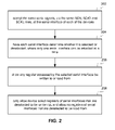
- FIG. 2 is a high level flow diagram that is useful for describing how a plurality of devices can share the same three serial lines, in accordance with specific embodiments of the present invention.
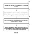
- FIG. 3 is a high level flow diagram of FIG. 2 that is useful for summarizing how a device having a serial interface can share the same three serial lines with other devices also having a serial interface, in accordance with specific embodiments of the present invention.
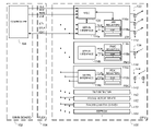
- FIG. 1 shows portions of an information recording/reproducing apparatus including a main circuit board 102 , a flex cable 104 and an optical pick-up unit (OPU) 106 .
- the main board 102 includes a controller 108 , which can also be referred to as a host controller, or simply a host.
- the main board can also include, e.g., an analog front end (AFE), a serial interface controller, and other devices not shown.
- the OPU 106 includes a laser diode driver integrated chip (LDD) 112 , a power monitor integrated chip (PMIC) 132 and a photo-detector integrated chip (PDIC) 142 .
- An LDD is also known as a laser driver integrated circuit (LDIC).
- the OPU 106 is also shown as including a tilt detector 152 , a focus motor driver 162 , a tracking motor driver 172 and an EEPROM 182 .
- the OPU 106 can also include additional devices (also referred to as subsystems) not shown, or less device than shown.
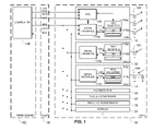
- the LDD 112 controls the current to laser diodes 122 , causing one of the laser diodes 122 to output a light signal that, after being appropriately focused by an optical system (not shown), is incident on an a optical media disk (not shown).
- the magnitude of the current provided by the LDD 112 (which controls the output power of the laser diode 122 ) can vary depending on whether the laser diode is being used to read data from or write data to the media. Further, the magnitude of the current may also depend on specific disc media, DVD, CD or Blue-ray Disk (BD) standards, and/or the speed at which data is being read or written.
- BD Blue-ray Disk
- the LDD 112 is shown as being capable of driving three different laser diodes 122 .
- one of the laser diodes outputs a wavelength of about 780 nm (which used in CD technology)
- another laser diode outputs a wavelength of about 655 nm (which is used in DVD technology)
- the remaining laser diode outputs a wavelength of about 405 nm (which is used for BD technology).
- LDD 112 can be used in CD, DVD and/or BD type devices.
- only one or two laser diode(s) can be used, if the LDD is only going to be used with one (or two) type(s) of technology.
- the LDD 112 drive more than three laser diodes.
- the laser diodes can output light signals of other wavelengths than those mentioned above.
- the LDD 112 is also shown as including a write strategy generator (WSG) 120 that implements an appropriate write strategy, which may depend, for example, on the media, CD, DVD or BD standards, and/or speed being supported.
- WSG 120 is shown as receiving a data clock (CLK) line, a read write mode (RWB) line, a data line labeled NRZ (Non-Return-to-Zero), and a land/groove bar (LBG) line used for DVD RAM type media.
- CLK data clock
- RWB read write mode
- NRZ Non-Return-to-Zero
- LBG land/groove bar
- a Low RWB signal can designate Write mode
- a High RWB signal can designate Read mode, or vice versa.
- the NRZ data line can alternatively support Return-to-Zero user data transfers.
- Other types of laser drivers where the WSG function is located in the controller 108 may also be used. When this is the case,
- the LDD 112 may also include other devices or subsystems, such as, but not limited to, an automatic power control (APC) subsystem, a running optical power control (ROPC) subsystem, drivers, analog-to-digital converters (DACs), oscillators, reference voltage circuitry, bias voltage circuitry, etc., many of which are controlled or programmed via registers 116 a of the LDD 112 .
- the registers 116 a can also include data that controls or programs the WSG 120 .
- a photo-detector 134 detects optical signals output by one of the laser diodes 122 before the light signals reach the media, and provides a signal representative of the detected intensity to the PMIC 132 .
- Multiple photo-detectors 144 detect the optical signal that has been reflected from the media (e.g., CD, DVD or BD media).
- An information signal produced by photo-detectors 144 includes user data, servo information and amplitude information. Samples of the amplitude of the information signal produced by the PDIC 142 can be provided to the ROPC circuit in the controller, which can adjust the laser power signal and current signal via the APC circuit to compensate for variations in the media. Samples of the signal produced by the photo-detector 134 , in contrast, can be used by the APC to compensate for temperature variations and aging of the laser diodes 122 .
- the LDD 112 is also shown as including a serial interface 114 a , which may also be referred to as a serial interface controller.
- the serial interface 114 a is shown as being connected to the controller 108 on the main board 102 across the flex 104 via three wires, which include a serial enable (SEN) line, a serial clock (SCLK) line and a bi-directional serial data input/output (SDIO) line.
- the SDIO line allows the controller 108 to write data to and read data from the registers 116 a within the LDD. Using these lines the controller 108 can program the LDD 112 .
- Signals sent across the SEN, SCLK and SDIO lines are referred to, respectively, as SEN, SCLK and SDIO signals, or simply enable, clock and data signals.
- SEN, SCLK and SDIO signals Signals sent across the SEN, SCLK and SDIO lines are referred to, respectively, as SEN, SCLK and SDIO signals, or simply enable, clock and data signals.
- additional wires/lines between the controller 108 on the main board 102 and devices on the OPU 106 but such additional wires need not be discussed because they are not relevant to the embodiments of the present invention.
- the PMIC 132 includes its own a serial interface 114 b , which is connected to the controller 108 on the main board 102 (across the flex 104 ) via the same SEN, SCLK and SDIO lines.
- the PMIC 132 also includes its own registers 1116 b .
- the PDIC 142 includes its own a serial interface 114 c , which is connected to the controller 108 on the main board 102 (across the flex 104 ) via the same SEN, SCLK and SDIO lines.
- the PDIC 142 also includes its own registers 116 c .
- the PMIC 132 and the PDIC 142 include additional portions not shown, which need not be discussed, because they are not relevant to the embodiments of the present invention.
- each device e.g., LDD, PMIC, PDIC, etc.
- DSR Device Select Register
- register 118 a of the LDD registers 116 a is designated the DSR for the LDD 112
- register 118 b of the PMIC registers 116 b is designated the DSR for the PMIC 132
- register 118 c of the PDIC registers 116 c is designated the DSR for the PMIC 142 .
- Additional devices of the OPU 106 can also include their own serial interface 114 , registers 116 , and DSR 118 . Examples of such devices include, but are not limited to, the tilt detector 152 , the focus motor driver 162 , the tracking motor driver 172 and the EEPROM 182 .
- each of the DSR registers 118 a , 118 b and 118 c has the same address, the reason for which will be clear from the description below.
- each device includes its own unique device enable number (DEN), which can be, e.g., an 8-bit number.
- DEN unique device enable number
- the DEN of each device is a metal masked number that is un-alterable. Other ways of assigning a DEN to a device are also possible, and within the scope of the present invention.
- Whether a serial interface 114 of a device is selected or deselected is controlled by the content of the DSR 118 of the device. More specifically, if the content of a device's DSR 118 is the DEN of that device, then the serial interface of the device is selected; otherwise the serial interface of the device is deselected. When the serial interface of a device is deselected, that serial interface 114 of that device acts as a listener for its DSR, during which time the controller 108 on the main board 102 can only write to the DSR 118 of that device. That is, when a serial interface 114 of a device is deselected, the only register of that device that can be written to is the DSR 118 of that device.
- the SEN line enables part of the serial interface control circuit whether or not the serial interface is enabled by the DEN and DSR or not. Specifically, the serial protocol first raises the SEN line. Then it clocks in a read/write bit. Then it clocks in address bits. Then if the serial interface is selected it clocks in the data bits to a shift register, followed by moving the contents of the shift register to the address specified. On the other hand, if the serial interface is deselected, the data is clocked into a shift register, but the contents of the shift register are not moved to the address specified.
- the serial interface If the serial interface is selected and it is a read cycle, the contents of the addressed register are fetched to a shift register, then the contents of the shift register are clocked back to the controller (e.g., 108 ). If the serial interface is deselected, and it is a read cycle, no data is fetched to the shift register, contents of the shift register are not clocked out, and the SDIO line remains, e.g., tri-state. Thus the action of the SEN (Serial Enable), does not fully enable the serial action unless the DEN matches the contents of the DSR.
- the controller e.g., 108
- the LDD 112 can be driving a laser diode 122 , even though the serial interface 114 a of the LDD 112 is deselected. This can be accomplished, as explained below.
- One or more register 118 of a device can be designated a control register that includes an enable bit, to which a “1” or a “0” can be written via the serial interface 114 of the device.
- a “1” written to the device enable bit can indicate that the device is enabled, where a “0” written to the device enable bit can indicate that the device is disabled.
- the serial interface 114 of a device can still be enabled, while the other portions of the device are disabled, so that the device can determine when it is to be enabled again.
- the DSR of the device can always be written to.
- each of the DSRs 118 a , 118 b , 118 c , etc. has the same address, if the address to which data is to be written is the address of the DSRs, then all the serial interfaces 114 that share the same SDIO will write the data to the DSR of their device.
- the controller 108 can specify which serial interface 114 (and thus, which device) is selected by writing data (a binary number) equal to one of the devices' DEN to the DSRs 118 of the multiples devices.
- every device on the OPU 106 has a DEN that differs from the DENs of the other devices, only one device at a time can include data (i.e., a binary number) in its DSR 118 that is the same as the DEN of the device, meaning only one serial interface 114 can be selected at a time.
- data i.e., a binary number
- a serial interface 114 of a device compares the device's DSN to the contents of the device's DSR 118 , to determine whether the serial interface is selected or deselected. As just mentioned, if the controller 108 is writing to the DSR register address, then all the serial interfaces 114 sharing the same three serial wires (SEN, SCLK, SDIO) will write to the DSR address. However, if the controller 108 is writing data to any other register address, then only the selected serial interface 114 will allow the data to be written. Also, if the controller 108 is reading data from a register (regardless of the address), then only the selected serial interface 114 will allow the data to be read.
- the DSR is address 0000011 (i.e., 03hex). If the address of a ‘write’ command is 03hex, then the serial interface writes to address 03hex (the DSR) with the received data. If this data matches the device's DEN, that serial interface of the device will then become “selected”. If not, the serial interface of the device would remain “deselected”. In a similar manner, a serial interface of a device that was previously “selected” can become “deselected”.
- multiple serial interfaces 114 of multiple devices can share the same three serial lines (e.g., SEN, SCLK, SDIO).
- An alternative to the above described embodiments would be for each serial interface (of each device on the OPU) to have their own three serial lines, but this would result in the flex including too many wires, which is undesirable.
- Another alternative to the above described embodiments would be each serial interface (of each device on the OPU) to share the same SCLK and SDIO lines but have their own SEN line. This may be fine if there were very few devices on the OPU that include a serial interface, however because there is a separate SEN line for each device with a serial interface, this would also result in more wires than desired on the flex 104 .
- a useful feature of specific embodiments of the present invention is that numerous (e.g., up to 256) different devices on the OPU 106 can share the same serial lines (e.g., three lines) by merely dedicating one 8-bit register (called the DSR) of each device to storing data to be compared to the DEN of the device. It is also possible that DENs are greater than 8 bits, and that multiple registers 118 of each device are used stored a value that is compared to a DEN that is more than 8 bits long. In other words, more than one register of a device can be designed a DSR. For example, each device can have a 16 bit DEN, and two 8-bit registers can be used as DSR, allowing for 2 ⁇ 16 devices to have their serial interfaces independently selected and deselected.
- the DSR 8-bit register
- each device can include a comparator that compares the contents of the DSR of the device to the DSN of the device.
- the design of the comparator that compares the DEN to the contents of the DSR can be done with an exclusive nor for each bit, followed with a wide AND gate. Thus when every bit matches, each exclusive nor outputs a 1 and the wide AND gate outputs a 1. If any bit does not match, that exclusive nor outputs a 0 and the wide AND gate outputs a zero. This is just one example of how the comparison can be accomplished. Other implementations are also within the scope of the present invention.
- one or more further register 118 can be designated a delayed digital select register (DDSR), which stores the most recent contents of an actual DSR, after the contents of the actual DSR are changed.
- DDSR delayed digital select register
- the contents of the DSR can first be shifted into the DDSR of the device.
- the contents of the DDSR can thereafter be read (presuming the serial interface of that device is selected), e.g., for purposes of debugging, and the like.
- one or more bits of a control register of a device can be designated a page select bit(s), enabling as many registers as desired to be addressable, and thus accessable.
- one page select bit can be used to select among two pages
- two page select bits can be used to select among four pages
- three select bits can be used to select among eight pages, etc.
- Embodiments of the present invention take advantage of the fast speeds that are available using three serial lines, including the SEN, SCLK and SDIO lines, while allowing multiple devices to share such lines.
- Embodiments of the present invention are believed to be preferable to use of a conventional I2C bus/interface, because the embodiments of the present invention provide for much faster data transfers than an I2C bus. This is at least in part because the I2C protocol is significantly more complicated, resulting in the slower speeds.
- the I2C interface uses resistor pull-ups, which slows down the signal speed.
- an I2C bus/interface can be useful for setting up a device, it is not fast enough to enable the changing of device parameters (e.g., power parameters) on-the-fly (i.e., in real-time), because the I2C interface is too slow.
- embodiments of the present invention are fast enough to enable the changing of power parameters, and the like, in real-time.
- the faster speeds obtainable using embodiments of the present invention are in part due to the use of the SEN line, which enables accurate and efficient framing of clock and data signals. For example, when the SEN line is low, a device will not expect a clock or data signal. However, when the SEN line goes high (from low), a device will expect the beginning of a clock signal and a data signal.
- Embodiments of the present invention can be used with various types of information recording/reproducing apparatuses, e.g., optical storage drives. More specific exemplary apparatuses include, but are not limited to, CD, DVD and Blue-ray drives, DVD or Blue-ray camcorders, and DVD or Blue-ray video recorders.
- embodiments of the present invention can be used to change power levels during the reading and/or writing of optical media (e.g., an optical disk), while I2C would be too slow to do so. Such changes to power levels may occur in response to a defect on the optical media, or when changing from reading to writing.
- optical media e.g., an optical disk
- I2C would be too slow to do so.
- Such changes to power levels may occur in response to a defect on the optical media, or when changing from reading to writing.
- embodiments of the present invention While especially useful with information recording/reproducing apparatuses, it is also possible to use embodiments of the present invention in other environments.
- embodiments of the present invention are especially useful for enabling multiple devices to share common serial lines, where the devices are located on an OPU
- embodiments of the present invention can also be useful where the multiple devices are not located on an OPU.
- embodiments of the present invention can be used in other environments where there is a desire for multiple devices to share common serial lines.
- Embodiments of the present invention are especially useful where there is a desire to provide for faster serial communications than are available using I2C communications.
- the high level flow diagram of FIG. 2 which includes steps 202 - 208 , is used to summarize a method, according to an embodiment of the present invention, for allowing a plurality of devices to share the same serial enable (SEN) line, the same serial clock (SCLK) line and the same serial data input/output (SDIO) line, where each device includes a serial interface and a plurality of registers accessible using the serial interface.
- SEN serial enable
- SCLK serial clock
- SDIO serial data input/output
- the high level flow diagram of FIG. 3 which includes steps 302 - 308 , is used to summarize a method, according to an embodiment of the present invention, for allowing a device having a serial interface to share the same serial enable (SEN), serial clock (SCLK) and serial data input/output (SDIO) lines with other devices also having a serial interface.
- SEN serial enable
- SCLK serial clock
- SDIO serial data input/output
Abstract
Description
- This application claims priority under 35 U.S.C. 119(e) to U.S. Patent Application No. 60/853,922, filed Oct. 24, 2006, entitled SYSTEMS AND METHODS FOR ALLOWING MULTIPLE DEVICES TO SHARE THE SAME SERIAL LINES, which is incorporated herein by reference.
- The present invention relates to systems and methods for allowing multiple devices to share the same serial lines. Such devices can be located, e.g., on an optical pick-up unit of a recording/reproducing apparatus, such as, but not limited to, DVD and CD drives, DVD camcorders, and DVD video recorders.
- Many devices may be located on an optical pickup unit (OPU) of a recording/reproducing apparatuses (such as DVD and CD drives, DVD camcorders, DVD video recorders, etc.). Such devices can include, e.g., a laser diode driver (LDD), a power monitor integrated circuit (PMIC), and a photo-detector integrated circuit (PDIC). Conventionally, many aspects of such devices were not programmable after the device was placed on the OPU. Or if they were programmable, were only capable of being programmed once. However, as more and more types of media and standards exist, and manufacturers desire that the same devices can be used with the different types of media and standards, there is a desire that the devices on an OPU can be programmed by a controller that is located on a main board connected to the OPU via a flex cable.
- There is also a desire to minimize the number of wires of the flex cable. Accordingly, it has been suggested that serial lines can be used to program at least one device on the OPU. For example, there exist some LDDs that include a serial interface, which can be used to program the LDD. More specifically, three serial lines, including a serial enable (SEN) line, a serial clock (SCLK) line and a serial data input/output (SDIO) line, which are part of the flex, have been used to write data to and read data from registers of LDDs. However, there is now a desire to program more than just the LDD.
- One solution would be for each device to have their own dedicated serial lines. However, this would result in the flex cable including too many wires, which is undesirable, and often unacceptable. Another possible solution would be for each device to share the same serial clock and data lines but have their own serial enable line. In this manner, each device would receive the same clock and data signals, but only one device (the one to which the appropriate enable signal was sent) would be written to or read from at a time. This solution may work if there were very few devices on the OPU that were to be programmed. However, because this solution requires a separate serial enable line for each device to be programmed, this would also result in more wires than desired on the flex cable, especially as the number of programmable devices increased. Accordingly, there is still a need for a better way of being able to program multiple devices on an OPU using a common serial interface. Preferably, the number of lines on a flex cable should not be increased by the solution.
- Embodiments of the present invention enable a plurality of devices to share the same serial lines. Such serial lines can include, e.g., a serial enable (SEN) line, a serial clock (SCLK) line and serial data input/output (SDIO) line. The plurality of devices can be devices that are configured to be on an optical pick-up unit (OPU). Examples of devices that are configured to be on an OPU include a laser diode driver (LDD) adapted to drive a laser diode, a power monitor integrated circuit (PMIC) to monitor the laser diode, and a photo-detector integrated circuit (PDIC) to detect light produced by the laser diode after the light has been reflected from an optical media. Further examples of devices configured to be on an OPU include, but are not limited to, a tilt detector, a focus motor driver, a tracking motor driver and an electrically erasable programmable read-only memory (EEPROM).
- In accordance with specific embodiments of the present invention, each device includes a serial interface that can be selected or deselected. Additionally, each device includes a device enable number (DEN) that differs from the DEN of each other device configured to be commonly located (e.g., on the same OPU). Each DEN is preferably un-alterable, and can be, e.g., a metal masked number. Further, each device includes a plurality of registers, with at least one register of the device being designated a device select register (DSR), and with the DSRs of the plurality of devices sharing a common address.
- The plurality of serial interfaces of the plurality of devices are configured to be connected to the same serial enable (SEN) line, the same serial clock (SCLK) line and the same serial data input/output (SDIO) line. Thus, the plurality of serial interfaces are collectively enabled and collectively disabled via the SEN line. However, only one of the plurality of serial interfaces can be selected at one time, with the remaining of the plurality of serial interfaces being deselected.
- In accordance with specific embodiments of the present invention, the serial interface of a device is selected when the DEN of the device is the same as the content of the at least one register designated the DSR of the device. Conversely, the serial interface of a device is deselected when the DEN of the device is not the same as the content of the at least one register designated the DSR of the device.
- In accordance with specific embodiments of the present invention, each serial interface of each device, in response to receiving a write command to the DSR of the device, will write to the DSR, thereby enabling changing of which one serial interface is selected.
- In accordance with specific embodiments of the present invention, when the serial interface of a device is selected, the registers of the device including the registers that are not the DSR can be written to in response to a write command received by the serial interface of the device, and read from in response to a read command received by the serial interface of the device. However, when the serial interface of a device is deselected, only the DSR of the device can be written to in response to a write commend received by the serial interface, and no registers of the device can be read from in response to a read command received by the serial interface.
- Further embodiments, and the features, aspects, and advantages of the present invention will become more apparent from the detailed description set forth below, the drawings and the
-
FIG. 1 is a high level block diagram of an information recording/reproducing apparatus, which is useful for describing embodiments of the present invention. -
FIG. 2 is a high level flow diagram that is useful for describing how a plurality of devices can share the same three serial lines, in accordance with specific embodiments of the present invention. -
FIG. 3 is a high level flow diagram ofFIG. 2 that is useful for summarizing how a device having a serial interface can share the same three serial lines with other devices also having a serial interface, in accordance with specific embodiments of the present invention. -
FIG. 1 shows portions of an information recording/reproducing apparatus including amain circuit board 102, aflex cable 104 and an optical pick-up unit (OPU) 106. Themain board 102 includes acontroller 108, which can also be referred to as a host controller, or simply a host. The main board can also include, e.g., an analog front end (AFE), a serial interface controller, and other devices not shown. The OPU 106 includes a laser diode driver integrated chip (LDD) 112, a power monitor integrated chip (PMIC) 132 and a photo-detector integrated chip (PDIC) 142. An LDD is also known as a laser driver integrated circuit (LDIC). The OPU 106 is also shown as including atilt detector 152, afocus motor driver 162, atracking motor driver 172 and an EEPROM 182. The OPU 106 can also include additional devices (also referred to as subsystems) not shown, or less device than shown. - The LDD 112 controls the current to
laser diodes 122, causing one of thelaser diodes 122 to output a light signal that, after being appropriately focused by an optical system (not shown), is incident on an a optical media disk (not shown). The magnitude of the current provided by the LDD 112 (which controls the output power of the laser diode 122) can vary depending on whether the laser diode is being used to read data from or write data to the media. Further, the magnitude of the current may also depend on specific disc media, DVD, CD or Blue-ray Disk (BD) standards, and/or the speed at which data is being read or written. - The LDD 112 is shown as being capable of driving three
different laser diodes 122. For example, one of the laser diodes outputs a wavelength of about 780 nm (which used in CD technology), another laser diode outputs a wavelength of about 655 nm (which is used in DVD technology), and the remaining laser diode outputs a wavelength of about 405 nm (which is used for BD technology). Accordingly, LDD 112 can be used in CD, DVD and/or BD type devices. Of course, only one or two laser diode(s) can be used, if the LDD is only going to be used with one (or two) type(s) of technology. Its also possible that the LDD 112 drive more than three laser diodes. Also, the laser diodes can output light signals of other wavelengths than those mentioned above. - The LDD 112 is also shown as including a write strategy generator (WSG) 120 that implements an appropriate write strategy, which may depend, for example, on the media, CD, DVD or BD standards, and/or speed being supported. The
WSG 120 is shown as receiving a data clock (CLK) line, a read write mode (RWB) line, a data line labeled NRZ (Non-Return-to-Zero), and a land/groove bar (LBG) line used for DVD RAM type media. A Low RWB signal can designate Write mode, and a High RWB signal can designate Read mode, or vice versa. The NRZ data line can alternatively support Return-to-Zero user data transfers. Other types of laser drivers where the WSG function is located in thecontroller 108 may also be used. When this is the case, the lines from the controller to the LDD can also include timing and amplitude information. - While not shown, the
LDD 112 may also include other devices or subsystems, such as, but not limited to, an automatic power control (APC) subsystem, a running optical power control (ROPC) subsystem, drivers, analog-to-digital converters (DACs), oscillators, reference voltage circuitry, bias voltage circuitry, etc., many of which are controlled or programmed viaregisters 116 a of theLDD 112. Theregisters 116 a can also include data that controls or programs theWSG 120. - A photo-
detector 134 detects optical signals output by one of thelaser diodes 122 before the light signals reach the media, and provides a signal representative of the detected intensity to thePMIC 132. Multiple photo-detectors 144 detect the optical signal that has been reflected from the media (e.g., CD, DVD or BD media). An information signal produced by photo-detectors 144 includes user data, servo information and amplitude information. Samples of the amplitude of the information signal produced by thePDIC 142 can be provided to the ROPC circuit in the controller, which can adjust the laser power signal and current signal via the APC circuit to compensate for variations in the media. Samples of the signal produced by the photo-detector 134, in contrast, can be used by the APC to compensate for temperature variations and aging of thelaser diodes 122. - The
LDD 112 is also shown as including aserial interface 114 a, which may also be referred to as a serial interface controller. Theserial interface 114 a is shown as being connected to thecontroller 108 on themain board 102 across theflex 104 via three wires, which include a serial enable (SEN) line, a serial clock (SCLK) line and a bi-directional serial data input/output (SDIO) line. The SDIO line allows thecontroller 108 to write data to and read data from theregisters 116 a within the LDD. Using these lines thecontroller 108 can program theLDD 112. Signals sent across the SEN, SCLK and SDIO lines are referred to, respectively, as SEN, SCLK and SDIO signals, or simply enable, clock and data signals. There are likely additional wires/lines between thecontroller 108 on themain board 102 and devices on theOPU 106, but such additional wires need not be discussed because they are not relevant to the embodiments of the present invention. - In accordance with specific embodiments of the present invention, the
PMIC 132 includes its own aserial interface 114 b, which is connected to thecontroller 108 on the main board 102 (across the flex 104) via the same SEN, SCLK and SDIO lines. ThePMIC 132 also includes its own registers 1116 b. Similarly, thePDIC 142 includes its own aserial interface 114 c, which is connected to thecontroller 108 on the main board 102 (across the flex 104) via the same SEN, SCLK and SDIO lines. ThePDIC 142 also includes its own registers 116 c. ThePMIC 132 and thePDIC 142 include additional portions not shown, which need not be discussed, because they are not relevant to the embodiments of the present invention. - In accordance with embodiments of the present invention, each device (e.g., LDD, PMIC, PDIC, etc.) that shares the same three serial lines (SEN, SCLK and SDIO) has one of its registers designated as a Device Select Register (DSR). More specifically, referring to
FIG. 1 , register 118 a of the LDD registers 116 a is designated the DSR for theLDD 112, register 118 b of the PMIC registers 116 b is designated the DSR for thePMIC 132, and register 118 c of the PDIC registers 116 c is designated the DSR for thePMIC 142. Additional devices of theOPU 106 can also include their own serial interface 114, registers 116, and DSR 118. Examples of such devices include, but are not limited to, thetilt detector 152, thefocus motor driver 162, the trackingmotor driver 172 and theEEPROM 182. - In accordance with an embodiment of the present invention, each of the DSR registers 118 a, 118 b and 118 c has the same address, the reason for which will be clear from the description below. Further, each device includes its own unique device enable number (DEN), which can be, e.g., an 8-bit number. In accordance with a preferred embodiment, the DEN of each device is a metal masked number that is un-alterable. Other ways of assigning a DEN to a device are also possible, and within the scope of the present invention.
- Whether a serial interface 114 of a device is selected or deselected is controlled by the content of the DSR 118 of the device. More specifically, if the content of a device's DSR 118 is the DEN of that device, then the serial interface of the device is selected; otherwise the serial interface of the device is deselected. When the serial interface of a device is deselected, that serial interface 114 of that device acts as a listener for its DSR, during which time the
controller 108 on themain board 102 can only write to the DSR 118 of that device. That is, when a serial interface 114 of a device is deselected, the only register of that device that can be written to is the DSR 118 of that device. This means that read/write commands to any other registers of that device are ignored, and that reading of the DSR 118 of that device is also ignored. Further, any read to a deselected device will not cause the deselected device to go through a read cycle. Thus only the selected device can answer back to the controller. - The SEN line enables part of the serial interface control circuit whether or not the serial interface is enabled by the DEN and DSR or not. Specifically, the serial protocol first raises the SEN line. Then it clocks in a read/write bit. Then it clocks in address bits. Then if the serial interface is selected it clocks in the data bits to a shift register, followed by moving the contents of the shift register to the address specified. On the other hand, if the serial interface is deselected, the data is clocked into a shift register, but the contents of the shift register are not moved to the address specified. If the serial interface is selected and it is a read cycle, the contents of the addressed register are fetched to a shift register, then the contents of the shift register are clocked back to the controller (e.g., 108). If the serial interface is deselected, and it is a read cycle, no data is fetched to the shift register, contents of the shift register are not clocked out, and the SDIO line remains, e.g., tri-state. Thus the action of the SEN (Serial Enable), does not fully enable the serial action unless the DEN matches the contents of the DSR.
- Further, when a serial interface 114 of a device is deselected or disabled, other portions of that device can be still be enabled. This is because the enablement and selection of the serial interface 114 is independent of the enablement of other portion of the device. For example, referring to
FIG. 1 , theLDD 112 can be driving alaser diode 122, even though theserial interface 114 a of theLDD 112 is deselected. This can be accomplished, as explained below. - One or more register 118 of a device (e.g., 112, 132, 142, etc.) can be designated a control register that includes an enable bit, to which a “1” or a “0” can be written via the serial interface 114 of the device. For example, a “1” written to the device enable bit can indicate that the device is enabled, where a “0” written to the device enable bit can indicate that the device is disabled. This allows devices to be placed in standby or sleep mode, for conserving power. However, in accordance with an embodiment of the present invention, the serial interface 114 of a device can still be enabled, while the other portions of the device are disabled, so that the device can determine when it is to be enabled again.
- As mentioned above, whether a serial interface 114 of a device is selected or deselected, the DSR of the device can always be written to. Remembering that each of the
DSRs controller 108 can specify which serial interface 114 (and thus, which device) is selected by writing data (a binary number) equal to one of the devices' DEN to the DSRs 118 of the multiples devices. Because every device on theOPU 106 has a DEN that differs from the DENs of the other devices, only one device at a time can include data (i.e., a binary number) in its DSR 118 that is the same as the DEN of the device, meaning only one serial interface 114 can be selected at a time. - A serial interface 114 of a device compares the device's DSN to the contents of the device's DSR 118, to determine whether the serial interface is selected or deselected. As just mentioned, if the
controller 108 is writing to the DSR register address, then all the serial interfaces 114 sharing the same three serial wires (SEN, SCLK, SDIO) will write to the DSR address. However, if thecontroller 108 is writing data to any other register address, then only the selected serial interface 114 will allow the data to be written. Also, if thecontroller 108 is reading data from a register (regardless of the address), then only the selected serial interface 114 will allow the data to be read. - For a more specific example, assume that the DSR is address 0000011 (i.e., 03hex). If the address of a ‘write’ command is 03hex, then the serial interface writes to address 03hex (the DSR) with the received data. If this data matches the device's DEN, that serial interface of the device will then become “selected”. If not, the serial interface of the device would remain “deselected”. In a similar manner, a serial interface of a device that was previously “selected” can become “deselected”.
- In the above described manner, multiple serial interfaces 114 of multiple devices can share the same three serial lines (e.g., SEN, SCLK, SDIO). An alternative to the above described embodiments would be for each serial interface (of each device on the OPU) to have their own three serial lines, but this would result in the flex including too many wires, which is undesirable. Another alternative to the above described embodiments would be each serial interface (of each device on the OPU) to share the same SCLK and SDIO lines but have their own SEN line. This may be fine if there were very few devices on the OPU that include a serial interface, however because there is a separate SEN line for each device with a serial interface, this would also result in more wires than desired on the
flex 104. - A useful feature of specific embodiments of the present invention is that numerous (e.g., up to 256) different devices on the
OPU 106 can share the same serial lines (e.g., three lines) by merely dedicating one 8-bit register (called the DSR) of each device to storing data to be compared to the DEN of the device. It is also possible that DENs are greater than 8 bits, and that multiple registers 118 of each device are used stored a value that is compared to a DEN that is more than 8 bits long. In other words, more than one register of a device can be designed a DSR. For example, each device can have a 16 bit DEN, and two 8-bit registers can be used as DSR, allowing for 2̂16 devices to have their serial interfaces independently selected and deselected. - In accordance with an embodiment, each device can include a comparator that compares the contents of the DSR of the device to the DSN of the device. For design flexibility, the design of the comparator that compares the DEN to the contents of the DSR can be done with an exclusive nor for each bit, followed with a wide AND gate. Thus when every bit matches, each exclusive nor outputs a 1 and the wide AND gate outputs a 1. If any bit does not match, that exclusive nor outputs a 0 and the wide AND gate outputs a zero. This is just one example of how the comparison can be accomplished. Other implementations are also within the scope of the present invention.
- In accordance with an embodiment of the present invention, one or more further register 118 can be designated a delayed digital select register (DDSR), which stores the most recent contents of an actual DSR, after the contents of the actual DSR are changed. For example, whenever a DSR of a device is to be written to, the contents of the DSR can first be shifted into the DDSR of the device. The contents of the DDSR can thereafter be read (presuming the serial interface of that device is selected), e.g., for purposes of debugging, and the like.
- In the above example, only 7 bits of data received over the SDIO line are used to designated an address, which would enable only 128 (2̂7) different registers to be addressed on a device. To increase this, one or more bits of a control register of a device can be designated a page select bit(s), enabling as many registers as desired to be addressable, and thus accessable. For example, one page select bit can be used to select among two pages, two page select bits can be used to select among four pages, three select bits can be used to select among eight pages, etc.
- Embodiments of the present invention take advantage of the fast speeds that are available using three serial lines, including the SEN, SCLK and SDIO lines, while allowing multiple devices to share such lines. Embodiments of the present invention are believed to be preferable to use of a conventional I2C bus/interface, because the embodiments of the present invention provide for much faster data transfers than an I2C bus. This is at least in part because the I2C protocol is significantly more complicated, resulting in the slower speeds. In addition the I2C interface uses resistor pull-ups, which slows down the signal speed.
- While an I2C bus/interface can be useful for setting up a device, it is not fast enough to enable the changing of device parameters (e.g., power parameters) on-the-fly (i.e., in real-time), because the I2C interface is too slow. In contrast, embodiments of the present invention are fast enough to enable the changing of power parameters, and the like, in real-time. The faster speeds obtainable using embodiments of the present invention are in part due to the use of the SEN line, which enables accurate and efficient framing of clock and data signals. For example, when the SEN line is low, a device will not expect a clock or data signal. However, when the SEN line goes high (from low), a device will expect the beginning of a clock signal and a data signal. Then, when the SEN goes low (from high), a device will expect the end of the clock signal and data signal. In other words, the use of the SEN line enables devices to easily determine the beginning and end of the clock and data signals. In contrast, I2C requires a hand-shaking/synchronization type of embedded communication to identify the beginning and end of such signals.
- Embodiments of the present invention can be used with various types of information recording/reproducing apparatuses, e.g., optical storage drives. More specific exemplary apparatuses include, but are not limited to, CD, DVD and Blue-ray drives, DVD or Blue-ray camcorders, and DVD or Blue-ray video recorders. For example, embodiments of the present invention can be used to change power levels during the reading and/or writing of optical media (e.g., an optical disk), while I2C would be too slow to do so. Such changes to power levels may occur in response to a defect on the optical media, or when changing from reading to writing. These are just a few exemplary applications for embodiments of the present invention, and are not meant to be limiting. Further, these are only a few examples of the advantages of the present invention over standard I2C communications.
- While especially useful with information recording/reproducing apparatuses, it is also possible to use embodiments of the present invention in other environments. For example, while the embodiments of the present invention are especially useful for enabling multiple devices to share common serial lines, where the devices are located on an OPU, embodiments of the present invention can also be useful where the multiple devices are not located on an OPU. In other words, embodiments of the present invention can be used in other environments where there is a desire for multiple devices to share common serial lines. Embodiments of the present invention are especially useful where there is a desire to provide for faster serial communications than are available using I2C communications.
- The high level flow diagram of
FIG. 2 , which includes steps 202-208, is used to summarize a method, according to an embodiment of the present invention, for allowing a plurality of devices to share the same serial enable (SEN) line, the same serial clock (SCLK) line and the same serial data input/output (SDIO) line, where each device includes a serial interface and a plurality of registers accessible using the serial interface. - The high level flow diagram of
FIG. 3 , which includes steps 302-308, is used to summarize a method, according to an embodiment of the present invention, for allowing a device having a serial interface to share the same serial enable (SEN), serial clock (SCLK) and serial data input/output (SDIO) lines with other devices also having a serial interface. - The forgoing description is of the preferred embodiments of the present invention. These embodiments have been provided for the purposes of illustration and description, but are not intended to be exhaustive or to limit the invention to the precise forms disclosed. Many modifications and variations will be apparent to a practitioner skilled in the art. Embodiments were chosen and described in order to best describe the principles of the invention and its practical application, thereby enabling others skilled in the art to understand the invention. It is intended that the scope of the invention be defined by the following claims and their equivalents.
Claims (25)
Priority Applications (1)
| Application Number | Priority Date | Filing Date | Title |
|---|---|---|---|
| US11/625,116 US7546397B2 (en) | 2006-10-24 | 2007-01-19 | Systems and methods for allowing multiple devices to share the same serial lines |
Applications Claiming Priority (2)
| Application Number | Priority Date | Filing Date | Title |
|---|---|---|---|
| US85392206P | 2006-10-24 | 2006-10-24 | |
| US11/625,116 US7546397B2 (en) | 2006-10-24 | 2007-01-19 | Systems and methods for allowing multiple devices to share the same serial lines |
Publications (2)
| Publication Number | Publication Date |
|---|---|
| US20080098144A1 true US20080098144A1 (en) | 2008-04-24 |
| US7546397B2 US7546397B2 (en) | 2009-06-09 |
Family
ID=39319398
Family Applications (1)
| Application Number | Title | Priority Date | Filing Date |
|---|---|---|---|
| US11/625,116 Expired - Fee Related US7546397B2 (en) | 2006-10-24 | 2007-01-19 | Systems and methods for allowing multiple devices to share the same serial lines |
Country Status (1)
| Country | Link |
|---|---|
| US (1) | US7546397B2 (en) |
Cited By (8)
| Publication number | Priority date | Publication date | Assignee | Title |
|---|---|---|---|---|
| US20100057961A1 (en) * | 2008-09-02 | 2010-03-04 | Hon Hai Precision Industry Co., Ltd. | Network device and data transmitting method |
| US20110055442A1 (en) * | 2009-08-27 | 2011-03-03 | Ward Michael G | Linear or rotational motor driver identification |
| US9172565B2 (en) | 2014-02-18 | 2015-10-27 | Allegro Microsystems, Llc | Signaling between master and slave components using a shared communication node of the master component |
| US9552315B2 (en) | 2009-01-16 | 2017-01-24 | Allegro Microsystems, Llc | Determining addresses of electrical components arranged in a daisy chain |
| US9634715B2 (en) | 2014-02-18 | 2017-04-25 | Allegro Microsystems, Llc | Signaling between master and slave components using a shared communication node of the master component |
| US9787495B2 (en) | 2014-02-18 | 2017-10-10 | Allegro Microsystems, Llc | Signaling between master and slave components using a shared communication node of the master component |
| US10747708B2 (en) | 2018-03-08 | 2020-08-18 | Allegro Microsystems, Llc | Communication system between electronic devices |
| US10783101B1 (en) | 2019-06-26 | 2020-09-22 | Semiconductor Components Industries, Llc | Methods and system for communication between a host device and slave devices |
Families Citing this family (1)
| Publication number | Priority date | Publication date | Assignee | Title |
|---|---|---|---|---|
| US20080162954A1 (en) * | 2006-12-31 | 2008-07-03 | Paul Lassa | Selectively powered data interfaces |
Citations (9)
| Publication number | Priority date | Publication date | Assignee | Title |
|---|---|---|---|---|
| US4343877A (en) * | 1981-01-02 | 1982-08-10 | Amdahl Corporation | System for design and production of integrated circuit photomasks and integrated circuit devices |
| US4888802A (en) * | 1988-06-17 | 1989-12-19 | Ncr Corporation | System and method for providing for secure encryptor key management |
| US5164916A (en) * | 1992-03-31 | 1992-11-17 | Digital Equipment Corporation | High-density double-sided multi-string memory module with resistor for insertion detection |
| US5319755A (en) * | 1990-04-18 | 1994-06-07 | Rambus, Inc. | Integrated circuit I/O using high performance bus interface |
| US5481753A (en) * | 1991-06-24 | 1996-01-02 | Mitsubishi Denki Kabushiki Kaisha | I/O device having identification register and data register where identification register indicates output from the data register to be an identifier or normal data |
| US5987614A (en) * | 1997-06-17 | 1999-11-16 | Vadem | Distributed power management system and method for computer |
| US20020095620A1 (en) * | 2000-09-13 | 2002-07-18 | Funai Electric Co., Ltd. | Two-MCU system and hang-up detecting method of MCU |
| US20040064602A1 (en) * | 2002-09-30 | 2004-04-01 | Varghese George | Claiming cycles on a processor bus in a system having a PCI to PCI bridge north of a memory controller |
| US6912361B2 (en) * | 2002-10-08 | 2005-06-28 | Finisar Corporation | Optical transceiver module with multipurpose internal serial bus |
Family Cites Families (1)
| Publication number | Priority date | Publication date | Assignee | Title |
|---|---|---|---|---|
| US7317674B2 (en) * | 2003-03-11 | 2008-01-08 | Intersil Americas Inc. | Optical pick-up units and laser drivers with increased functionality |
-
2007
- 2007-01-19 US US11/625,116 patent/US7546397B2/en not_active Expired - Fee Related
Patent Citations (9)
| Publication number | Priority date | Publication date | Assignee | Title |
|---|---|---|---|---|
| US4343877A (en) * | 1981-01-02 | 1982-08-10 | Amdahl Corporation | System for design and production of integrated circuit photomasks and integrated circuit devices |
| US4888802A (en) * | 1988-06-17 | 1989-12-19 | Ncr Corporation | System and method for providing for secure encryptor key management |
| US5319755A (en) * | 1990-04-18 | 1994-06-07 | Rambus, Inc. | Integrated circuit I/O using high performance bus interface |
| US5481753A (en) * | 1991-06-24 | 1996-01-02 | Mitsubishi Denki Kabushiki Kaisha | I/O device having identification register and data register where identification register indicates output from the data register to be an identifier or normal data |
| US5164916A (en) * | 1992-03-31 | 1992-11-17 | Digital Equipment Corporation | High-density double-sided multi-string memory module with resistor for insertion detection |
| US5987614A (en) * | 1997-06-17 | 1999-11-16 | Vadem | Distributed power management system and method for computer |
| US20020095620A1 (en) * | 2000-09-13 | 2002-07-18 | Funai Electric Co., Ltd. | Two-MCU system and hang-up detecting method of MCU |
| US20040064602A1 (en) * | 2002-09-30 | 2004-04-01 | Varghese George | Claiming cycles on a processor bus in a system having a PCI to PCI bridge north of a memory controller |
| US6912361B2 (en) * | 2002-10-08 | 2005-06-28 | Finisar Corporation | Optical transceiver module with multipurpose internal serial bus |
Cited By (9)
| Publication number | Priority date | Publication date | Assignee | Title |
|---|---|---|---|---|
| US20100057961A1 (en) * | 2008-09-02 | 2010-03-04 | Hon Hai Precision Industry Co., Ltd. | Network device and data transmitting method |
| US9552315B2 (en) | 2009-01-16 | 2017-01-24 | Allegro Microsystems, Llc | Determining addresses of electrical components arranged in a daisy chain |
| US20110055442A1 (en) * | 2009-08-27 | 2011-03-03 | Ward Michael G | Linear or rotational motor driver identification |
| US8461782B2 (en) * | 2009-08-27 | 2013-06-11 | Allegro Microsystems, Llc | Linear or rotational motor driver identification |
| US9172565B2 (en) | 2014-02-18 | 2015-10-27 | Allegro Microsystems, Llc | Signaling between master and slave components using a shared communication node of the master component |
| US9634715B2 (en) | 2014-02-18 | 2017-04-25 | Allegro Microsystems, Llc | Signaling between master and slave components using a shared communication node of the master component |
| US9787495B2 (en) | 2014-02-18 | 2017-10-10 | Allegro Microsystems, Llc | Signaling between master and slave components using a shared communication node of the master component |
| US10747708B2 (en) | 2018-03-08 | 2020-08-18 | Allegro Microsystems, Llc | Communication system between electronic devices |
| US10783101B1 (en) | 2019-06-26 | 2020-09-22 | Semiconductor Components Industries, Llc | Methods and system for communication between a host device and slave devices |
Also Published As
| Publication number | Publication date |
|---|---|
| US7546397B2 (en) | 2009-06-09 |
Similar Documents
| Publication | Publication Date | Title |
|---|---|---|
| US7546397B2 (en) | Systems and methods for allowing multiple devices to share the same serial lines | |
| CN1230809C (en) | Laser diode drive and initialization method of driving and opitical recording reconstruction device | |
| KR100442860B1 (en) | Output control apparatus of laser diode | |
| US7317674B2 (en) | Optical pick-up units and laser drivers with increased functionality | |
| CN1322497C (en) | Disk drive device | |
| US20030214893A1 (en) | Apparatus and method for controlling laser power for disc drive | |
| US5991251A (en) | Method and apparatus for changing laser beam power of an optical storage device for various types of compact disks | |
| KR19990016023A (en) | Laser diode light output control method and device | |
| CN100541615C (en) | Disc drive unit and signal processing method | |
| CN100501839C (en) | Recording pulse generating apparatus and information recording apparatus | |
| US20040037191A1 (en) | Pickup device | |
| KR100510498B1 (en) | Method and apparatus for recording data in defect disc | |
| JP4127519B2 (en) | Power saving method and drive device | |
| US20030031105A1 (en) | Optical disc drive | |
| CN1928996B (en) | Method for correcting write strategy data of an optical disc and optical disc drive using the same | |
| JP2006209873A (en) | Photodetector, optical pickup device, and optical disk device | |
| KR100280247B1 (en) | Data signal reproducing method and system | |
| US20070109937A1 (en) | Write based power adaptive control system | |
| CN101373606A (en) | Method and system for signal gain control in optical disc drives | |
| JP2002298372A (en) | Light receiving signal processor | |
| TWI440027B (en) | Apparatus of optical storage and method of eliminating transition for writing power thereof | |
| CN1983403A (en) | Apparatus and method for controlling a recording light signal | |
| JP2004086960A (en) | Power calibration method of optical disk drive | |
| US7660219B2 (en) | Write adjustment method | |
| JP4285397B2 (en) | Optical pickup unit control method and optical disk apparatus |
Legal Events
| Date | Code | Title | Description |
|---|---|---|---|
| AS | Assignment |
Owner name: INTERSIL AMERICAS INC, CALIFORNIA Free format text: ASSIGNMENT OF ASSIGNORS INTEREST;ASSIGNORS:REES, THEODORE D.;SMITH, D. STUART;ZHENG, DONG;REEL/FRAME:018781/0658;SIGNING DATES FROM 20070108 TO 20070115 |
|
| AS | Assignment |
Owner name: MORGAN STANLEY & CO. INCORPORATED,NEW YORK Free format text: SECURITY AGREEMENT;ASSIGNORS:INTERSIL CORPORATION;TECHWELL, INC.;INTERSIL COMMUNICATIONS, INC.;AND OTHERS;REEL/FRAME:024329/0411 Effective date: 20100427 Owner name: MORGAN STANLEY & CO. INCORPORATED, NEW YORK Free format text: SECURITY AGREEMENT;ASSIGNORS:INTERSIL CORPORATION;TECHWELL, INC.;INTERSIL COMMUNICATIONS, INC.;AND OTHERS;REEL/FRAME:024329/0411 Effective date: 20100427 |
|
| FPAY | Fee payment |
Year of fee payment: 4 |
|
| AS | Assignment |
Owner name: INTERSIL AMERICAS LLC, CALIFORNIA Free format text: CHANGE OF NAME;ASSIGNOR:INTERSIL AMERICAS INC.;REEL/FRAME:033119/0484 Effective date: 20111223 |
|
| REMI | Maintenance fee reminder mailed | ||
| LAPS | Lapse for failure to pay maintenance fees | ||
| STCH | Information on status: patent discontinuation |
Free format text: PATENT EXPIRED DUE TO NONPAYMENT OF MAINTENANCE FEES UNDER 37 CFR 1.362 |
|
| FP | Lapsed due to failure to pay maintenance fee |
Effective date: 20170609 |