US20080098171A1 - System and method for implementing a meta-disk aggregation model for storage controllers - Google Patents
System and method for implementing a meta-disk aggregation model for storage controllers Download PDFInfo
- Publication number
- US20080098171A1 US20080098171A1 US11/585,524 US58552406A US2008098171A1 US 20080098171 A1 US20080098171 A1 US 20080098171A1 US 58552406 A US58552406 A US 58552406A US 2008098171 A1 US2008098171 A1 US 2008098171A1
- Authority
- US
- United States
- Prior art keywords
- meta
- drive
- disk
- disk drive
- group
- Prior art date
- Legal status (The legal status is an assumption and is not a legal conclusion. Google has not performed a legal analysis and makes no representation as to the accuracy of the status listed.)
- Granted
Links
Images


Classifications
-
- G—PHYSICS
- G06—COMPUTING; CALCULATING OR COUNTING
- G06F—ELECTRIC DIGITAL DATA PROCESSING
- G06F3/00—Input arrangements for transferring data to be processed into a form capable of being handled by the computer; Output arrangements for transferring data from processing unit to output unit, e.g. interface arrangements
- G06F3/06—Digital input from, or digital output to, record carriers, e.g. RAID, emulated record carriers or networked record carriers
- G06F3/0601—Interfaces specially adapted for storage systems
- G06F3/0628—Interfaces specially adapted for storage systems making use of a particular technique
- G06F3/0655—Vertical data movement, i.e. input-output transfer; data movement between one or more hosts and one or more storage devices
- G06F3/0658—Controller construction arrangements
-
- G—PHYSICS
- G06—COMPUTING; CALCULATING OR COUNTING
- G06F—ELECTRIC DIGITAL DATA PROCESSING
- G06F3/00—Input arrangements for transferring data to be processed into a form capable of being handled by the computer; Output arrangements for transferring data from processing unit to output unit, e.g. interface arrangements
- G06F3/06—Digital input from, or digital output to, record carriers, e.g. RAID, emulated record carriers or networked record carriers
- G06F3/0601—Interfaces specially adapted for storage systems
- G06F3/0602—Interfaces specially adapted for storage systems specifically adapted to achieve a particular effect
- G06F3/061—Improving I/O performance
-
- G—PHYSICS
- G06—COMPUTING; CALCULATING OR COUNTING
- G06F—ELECTRIC DIGITAL DATA PROCESSING
- G06F3/00—Input arrangements for transferring data to be processed into a form capable of being handled by the computer; Output arrangements for transferring data from processing unit to output unit, e.g. interface arrangements
- G06F3/06—Digital input from, or digital output to, record carriers, e.g. RAID, emulated record carriers or networked record carriers
- G06F3/0601—Interfaces specially adapted for storage systems
- G06F3/0668—Interfaces specially adapted for storage systems adopting a particular infrastructure
- G06F3/0671—In-line storage system
- G06F3/0683—Plurality of storage devices
- G06F3/0689—Disk arrays, e.g. RAID, JBOD
Definitions
- the present invention relates to the field of electronic data storage and particularly to a meta-disk aggregation model for storage controllers.
- a number of current disk arrays may be capable of handling heterogeneous drive types across drive enclosures that are attached to back-end controller channels in order to provide volumes and volume groups made up of disk volume groups.
- current storage system controllers provide the capability to create volumes and volume groups by combining one or more drives depending on the required RAID level.
- disk I/O (input/output) performance may be limited by factors such as: number of drives in the volume group; RAID level; number of volumes within the volume group; and size of volumes and volume groups.
- an embodiment of the present invention is directed to a system for implementing a meta-disk aggregation model for storage controllers, including: a storage controller configured for communicatively coupling with a server; and a meta-disk drive group including a plurality of disk drives, the meta-disk drive group configured for being communicatively coupled with the storage controller, each of the plurality of disk drives including a drive interface connector, wherein each drive interface connector of the plurality of disk drives of the meta-disk drive group is configured for being communicatively coupled to each of the remaining drive interface connectors of the plurality of disk drives, thereby allowing the plurality of disk drives to communicate as a single device with the storage controller.
- a further embodiment of the present invention is directed to a method for implementing a meta-disk aggregation model for storage controllers, including: providing a storage controller configured for communicatively coupling with a server; providing a meta-disk drive group, the meta-disk drive group including a plurality of disk drives; and configuring the meta-disk drive group for being communicatively coupleable as a single device with the storage controller.
- An additional embodiment of the present invention is directed to a system for implementing a meta-disk aggregation model for storage controllers, including: a storage controller configured for communicatively coupling with a server; and a meta-disk drive group including a plurality of disk drives, each disk drive of the plurality of disk drives of the meta-disk drive group having a drive carrier assembly including a drive pull mechanism, each drive pull mechanism configured for allowing disk drive and drive carrier assembly removal from a drive enclosure, each drive pull mechanism of the meta-disk drive group being interlocked and synchronized with remaining drive pull mechanisms of the meta-disk drive group, thereby allowing for coordinated removal of each disk drive and drive carrier assembly from the drive enclosure, each drive pull mechanism of the meta-disk drive group including an extraction lock and an extraction lever, the meta-disk drive group configured for being communicatively coupled with the storage controller, wherein a single device address is assigned to the meta-disk drive group with the plurality of disk drives of the meta-disk drive group being configured to communicate as a
- FIG. 1 is an illustration of a system implementing a meta-disk aggregation model for storage controllers in accordance with an exemplary embodiment of the present invention
- FIG. 2 is an illustration of a drive interface connector of a disk drive included in a system implementing a meta-disk aggregation model for storage controllers in accordance with an exemplary embodiment of the present invention
- FIG. 3 is an illustration of drive pull mechanisms for disk drives included in a system implementing a meta-disk aggregation model for storage controllers in accordance with an exemplary embodiment of the present invention
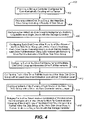
- FIG. 4 is a flow chart illustrating a method for implementing a meta-disk aggregation model for storage controllers in accordance with an exemplary embodiment of the present invention.
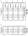
- FIG. 5A is an illustration of a conventional prior art volume group model
- FIG. 5B is an illustration of a system implementing a meta-drive aggregation model for storage controllers in accordance with an exemplary embodiment of the present invention.
- FIG. 1 illustrates a system 100 implementing a meta-disk aggregation model in accordance with an exemplary embodiment of the present invention.
- the system 100 includes a storage controller 102 .
- the storage controller 102 may be an EngenioTM storage controller.
- the storage controller 100 may be configured for communicatively coupling with a server 104 , such as via a Fibre Channel (FC), internet SCSI (iSCSI), or serial attached SCSI (SAS) connection.
- FC Fibre Channel
- iSCSI internet SCSI
- SAS serial attached SCSI
- the system 100 further includes a meta-disk drive group 106 including a plurality of disk drives 108 .
- the meta-disk drive group 106 is configured for being communicatively coupled with the storage controller 102 , such as via a Fibre Channel (FC) or serial attached SCSI (SAS) connection.
- the plurality of disk drives 108 of the meta-disk drive group 106 are configured for communicating as a single device with the storage controller 102 .
- the storage controller 102 interprets the plurality of disk drives as being a single device (ex.—a single meta-disk spindle) thus, a single device address may be assigned to the meta-disk drive group 106 , thereby promoting increased I/O throughput and increased storage density for the system 100 .
- I/O traffic may be directed to the single device address of the meta-disk drive group via a back-end channel of the storage controller 102 .
- each disk drive included in the plurality of disk drives 108 of the meta-disk drive group includes a drive carrier assembly 202 having a drive pull mechanism 204 .
- each drive pull mechanism 204 includes an extraction lock 206 for securing the drive carrier assembly 202 within a drive enclosure 208 , said extraction lock being disengageable to allow for extraction of the drive carrier assembly and disk drive from the drive enclosure.
- each drive pull mechanism 204 also includes an extraction lever 210 for promoting extraction of the drive carrier assembly 202 and disk drive from the drive enclosure.
- each of the drive pull mechanisms 204 of the disk drives 108 of the meta-disk drive group 106 are interlocked and synchronized so that, for example, while a user is extracting or removing a drive carrier assembly 202 and disk drive 108 of the meta-disk drive group 106 from the drive enclosure, each of the remaining drive carrier assemblies and disk drives 108 of meta-disk drive group 106 are also extracted.
- multiple meta-disk drive groups 106 may be enclosed by a single drive enclosure 208 .
- the disk drives 108 may be aggregated to a desired capacity to form a meta-disk drive group 106 having a desired number of disk drives.
- multiple meta-disk drive groups 106 may be included in the system 100 , for providing a volume group 500 which promotes increased capacity and I/O performance bandwidth over a conventional prior art volume group 502 (see FIG. 5A ).
- each of the plurality of disk drives 108 of the meta-disk drive group 106 include a drive interface connector 302 .
- each of the plurality of disk drives 108 of the meta-disk drive group 106 include on-interposer electronics, such as a jumper 304 (ex—an interposer jumper), for communicatively coupling each of the plurality of disk drives of the meta-disk drive group via the drive interface connectors 302 of the disk drives.
- each jumper 304 is configured for indicating aggregation of the plurality of disk drives 108 of the meta-disk drive group 106 to the storage controller 102 . For instance, aggregation may be indicated to the storage controller during boot up (i.e., power on) of the storage controller or when device discovery is performed by the storage controller.
- FIG. 4 is a flowchart illustrating a method for implementing a meta-disk aggregation model for storage controllers in accordance with an embodiment of the present invention.
- the method 400 includes the step of providing a storage controller configured for communicatively coupling with a server 402 .
- the method 400 further includes the step of providing a meta-disk drive group, the meta-disk drive group including a plurality of disk drives 404 .
- the method 400 further includes the step of configuring the meta-disk drive group for being communicatively coupleable as a single device with the storage controller 406 .
- the method 400 further includes the step of configuring each disk drive of the plurality of disk drives of the meta-disk drive group with a drive carrier assembly, each drive carrier assembly having a drive pull mechanism, each drive pull mechanism being synchronized with remaining drive pull mechanisms of the meta-disk drive group 408 .
- the method 400 further includes the step of configuring each of the drive pull mechanisms of the meta-disk drive group as interlocked drive pull mechanisms 410 .
- the method 400 further includes the step of configuring each of the drive pull mechanisms of the meta-disk drive group with at least one of an extraction lock and an extraction lever 412 .
- the method 400 further includes the step of configuring each of the plurality of disk drives of the meta-disk drive group with a drive interface connector and a jumper 414 .
- the method 400 further includes the step of bridging each of the drive interface connectors of the disk drives via the jumpers of the disk drives to allow for communicative coupling of the disk drives of the meta-disk drive group and to further allow the disk drives of the meta-disk drive group to communicate as a single device with the storage controller 416 .
- Such a software package may be a computer program product which employs a computer-readable storage medium including stored computer code which is used to program a computer to perform the disclosed function and process of the present invention.
- the computer-readable medium may include, but is not limited to, any type of conventional floppy disk, optical disk, CD-ROM, magnetic disk, hard disk drive, magneto-optical disk, ROM, RAM, EPROM, EEPROM, magnetic or optical card, or any other suitable media for storing electronic instructions.
Abstract
Description
- The present invention relates to the field of electronic data storage and particularly to a meta-disk aggregation model for storage controllers.
- A number of current disk arrays may be capable of handling heterogeneous drive types across drive enclosures that are attached to back-end controller channels in order to provide volumes and volume groups made up of disk volume groups. In addition, current storage system controllers provide the capability to create volumes and volume groups by combining one or more drives depending on the required RAID level. However, with current systems, disk I/O (input/output) performance may be limited by factors such as: number of drives in the volume group; RAID level; number of volumes within the volume group; and size of volumes and volume groups.
- Therefore, it may be desirable to provide a meta-disk aggregation model for storage controllers which addresses the above-referenced problems and limitations of the current solutions by promoting improved disk I/O throughput and by further promoting increased system storage density.
- Accordingly, an embodiment of the present invention is directed to a system for implementing a meta-disk aggregation model for storage controllers, including: a storage controller configured for communicatively coupling with a server; and a meta-disk drive group including a plurality of disk drives, the meta-disk drive group configured for being communicatively coupled with the storage controller, each of the plurality of disk drives including a drive interface connector, wherein each drive interface connector of the plurality of disk drives of the meta-disk drive group is configured for being communicatively coupled to each of the remaining drive interface connectors of the plurality of disk drives, thereby allowing the plurality of disk drives to communicate as a single device with the storage controller.
- A further embodiment of the present invention is directed to a method for implementing a meta-disk aggregation model for storage controllers, including: providing a storage controller configured for communicatively coupling with a server; providing a meta-disk drive group, the meta-disk drive group including a plurality of disk drives; and configuring the meta-disk drive group for being communicatively coupleable as a single device with the storage controller.
- An additional embodiment of the present invention is directed to a system for implementing a meta-disk aggregation model for storage controllers, including: a storage controller configured for communicatively coupling with a server; and a meta-disk drive group including a plurality of disk drives, each disk drive of the plurality of disk drives of the meta-disk drive group having a drive carrier assembly including a drive pull mechanism, each drive pull mechanism configured for allowing disk drive and drive carrier assembly removal from a drive enclosure, each drive pull mechanism of the meta-disk drive group being interlocked and synchronized with remaining drive pull mechanisms of the meta-disk drive group, thereby allowing for coordinated removal of each disk drive and drive carrier assembly from the drive enclosure, each drive pull mechanism of the meta-disk drive group including an extraction lock and an extraction lever, the meta-disk drive group configured for being communicatively coupled with the storage controller, wherein a single device address is assigned to the meta-disk drive group with the plurality of disk drives of the meta-disk drive group being configured to communicate as a single device with the storage controller.
- It is to be understood that both the foregoing general description and the following detailed description are exemplary and explanatory only and are not necessarily restrictive of the invention as claimed. The accompanying drawings, which are incorporated in and constitute a part of the specification, illustrate embodiments of the invention and together with the general description, serve to explain the principles of the invention.
- The numerous advantages of the present invention may be better understood by those skilled in the art by reference to the accompanying figures in which:
-
FIG. 1 is an illustration of a system implementing a meta-disk aggregation model for storage controllers in accordance with an exemplary embodiment of the present invention; -
FIG. 2 is an illustration of a drive interface connector of a disk drive included in a system implementing a meta-disk aggregation model for storage controllers in accordance with an exemplary embodiment of the present invention; -
FIG. 3 is an illustration of drive pull mechanisms for disk drives included in a system implementing a meta-disk aggregation model for storage controllers in accordance with an exemplary embodiment of the present invention; -
FIG. 4 is a flow chart illustrating a method for implementing a meta-disk aggregation model for storage controllers in accordance with an exemplary embodiment of the present invention. -
FIG. 5A is an illustration of a conventional prior art volume group model; and -
FIG. 5B is an illustration of a system implementing a meta-drive aggregation model for storage controllers in accordance with an exemplary embodiment of the present invention. - Reference will now be made in detail to the presently preferred embodiments of the invention, examples of which are illustrated in the accompanying drawings.
-
FIG. 1 illustrates asystem 100 implementing a meta-disk aggregation model in accordance with an exemplary embodiment of the present invention. In a present embodiment, thesystem 100 includes astorage controller 102. For example, thestorage controller 102 may be an Engenio™ storage controller. In the exemplary embodiment, thestorage controller 100 may be configured for communicatively coupling with aserver 104, such as via a Fibre Channel (FC), internet SCSI (iSCSI), or serial attached SCSI (SAS) connection. - In a current embodiment, the
system 100 further includes a meta-disk drive group 106 including a plurality ofdisk drives 108. In the exemplary embodiment, the meta-disk drive group 106 is configured for being communicatively coupled with thestorage controller 102, such as via a Fibre Channel (FC) or serial attached SCSI (SAS) connection. In present embodiments, the plurality of disk drives 108 of the meta-disk drive group 106 are configured for communicating as a single device with thestorage controller 102. For instance, although the meta-disk drive group 106 includes a plurality ofdisk drives 108, thestorage controller 102 interprets the plurality of disk drives as being a single device (ex.—a single meta-disk spindle) thus, a single device address may be assigned to the meta-disk drive group 106, thereby promoting increased I/O throughput and increased storage density for thesystem 100. In exemplary embodiments, I/O traffic may be directed to the single device address of the meta-disk drive group via a back-end channel of thestorage controller 102. - In exemplary embodiments, as shown in
FIG. 2 , each disk drive included in the plurality ofdisk drives 108 of the meta-disk drive group includes adrive carrier assembly 202 having adrive pull mechanism 204. In the present embodiment, eachdrive pull mechanism 204 includes an extraction lock 206 for securing thedrive carrier assembly 202 within adrive enclosure 208, said extraction lock being disengageable to allow for extraction of the drive carrier assembly and disk drive from the drive enclosure. In additional embodiments, eachdrive pull mechanism 204 also includes anextraction lever 210 for promoting extraction of thedrive carrier assembly 202 and disk drive from the drive enclosure. In exemplary embodiments, each of thedrive pull mechanisms 204 of thedisk drives 108 of the meta-disk drive group 106 are interlocked and synchronized so that, for example, while a user is extracting or removing adrive carrier assembly 202 anddisk drive 108 of the meta-disk drive group 106 from the drive enclosure, each of the remaining drive carrier assemblies anddisk drives 108 of meta-disk drive group 106 are also extracted. As shown inFIG. 2 , multiple meta-disk drive groups 106 may be enclosed by asingle drive enclosure 208. - In further embodiments, the
disk drives 108 may be aggregated to a desired capacity to form a meta-disk drive group 106 having a desired number of disk drives. In additional embodiments, as shown inFIG. 5B , multiple meta-disk drive groups 106 may be included in thesystem 100, for providing avolume group 500 which promotes increased capacity and I/O performance bandwidth over a conventional prior art volume group 502 (seeFIG. 5A ). - In additional embodiments, as shown in
FIG. 3 , each of the plurality ofdisk drives 108 of the meta-disk drive group 106 include adrive interface connector 302. Further, each of the plurality of disk drives 108 of the meta-disk drive group 106 include on-interposer electronics, such as a jumper 304 (ex—an interposer jumper), for communicatively coupling each of the plurality of disk drives of the meta-disk drive group via thedrive interface connectors 302 of the disk drives. In exemplary embodiments, eachjumper 304 is configured for indicating aggregation of the plurality ofdisk drives 108 of the meta-disk drive group 106 to thestorage controller 102. For instance, aggregation may be indicated to the storage controller during boot up (i.e., power on) of the storage controller or when device discovery is performed by the storage controller. -
FIG. 4 is a flowchart illustrating a method for implementing a meta-disk aggregation model for storage controllers in accordance with an embodiment of the present invention. Themethod 400 includes the step of providing a storage controller configured for communicatively coupling with aserver 402. Themethod 400 further includes the step of providing a meta-disk drive group, the meta-disk drive group including a plurality ofdisk drives 404. Themethod 400 further includes the step of configuring the meta-disk drive group for being communicatively coupleable as a single device with thestorage controller 406. Themethod 400 further includes the step of configuring each disk drive of the plurality of disk drives of the meta-disk drive group with a drive carrier assembly, each drive carrier assembly having a drive pull mechanism, each drive pull mechanism being synchronized with remaining drive pull mechanisms of the meta-disk drive group 408. Themethod 400 further includes the step of configuring each of the drive pull mechanisms of the meta-disk drive group as interlockeddrive pull mechanisms 410. Themethod 400 further includes the step of configuring each of the drive pull mechanisms of the meta-disk drive group with at least one of an extraction lock and anextraction lever 412. Themethod 400 further includes the step of configuring each of the plurality of disk drives of the meta-disk drive group with a drive interface connector and ajumper 414. Themethod 400 further includes the step of bridging each of the drive interface connectors of the disk drives via the jumpers of the disk drives to allow for communicative coupling of the disk drives of the meta-disk drive group and to further allow the disk drives of the meta-disk drive group to communicate as a single device with thestorage controller 416. - It is to be noted that the foregoing described embodiments according to the present invention may be conveniently implemented using conventional general purpose digital computers programmed according to the teachings of the present specification, as will be apparent to those skilled in the computer art. Appropriate software coding may readily be prepared by skilled programmers based on the teachings of the present disclosure, as will be apparent to those skilled in the software art.
- It is to be understood that the present invention may be conveniently implemented in forms of a software package. Such a software package may be a computer program product which employs a computer-readable storage medium including stored computer code which is used to program a computer to perform the disclosed function and process of the present invention. The computer-readable medium may include, but is not limited to, any type of conventional floppy disk, optical disk, CD-ROM, magnetic disk, hard disk drive, magneto-optical disk, ROM, RAM, EPROM, EEPROM, magnetic or optical card, or any other suitable media for storing electronic instructions.
- It is understood that the specific order or hierarchy of steps in the foregoing disclosed methods are examples of exemplary approaches. Based upon design preferences, it is understood that the specific order or hierarchy of steps in the method can be rearranged while remaining within the scope of the present invention. The accompanying method claims present elements of the various steps in a sample order, and are not meant to be limited to the specific order or hierarchy presented.
- It is believed that the present invention and many of its attendant advantages will be understood by the foregoing description. It is also believed that it will be apparent that various changes may be made in the form, construction and arrangement of the components thereof without departing from the scope and spirit of the invention or without sacrificing all of its material advantages. The form herein before described being merely an explanatory embodiment thereof, it is the intention of the following claims to encompass and include such changes.
Claims (20)
Priority Applications (6)
| Application Number | Priority Date | Filing Date | Title |
|---|---|---|---|
| US11/585,524 US8385061B2 (en) | 2006-10-24 | 2006-10-24 | System and method for implementing a meta-disk aggregation model for storage controllers |
| PCT/US2007/021085 WO2008051353A2 (en) | 2006-10-24 | 2007-09-28 | System and method for implementing a meta-disk aggregation model for storage controllers |
| CN2007800378954A CN101523363B (en) | 2006-10-24 | 2007-09-28 | System and method for implementing a meta-disk aggregation model for storage controllers |
| EP07839105A EP2087432A4 (en) | 2006-10-24 | 2007-09-28 | System and method for implementing a meta-disk aggregation model for storage controllers |
| JP2009534580A JP2010507867A (en) | 2006-10-24 | 2007-09-28 | System and method for implementing a meta-disk aggregate model for a storage controller |
| JP2012232276A JP2013041606A (en) | 2006-10-24 | 2012-10-19 | System and method for implementing meta-disk aggregation model for storage controllers |
Applications Claiming Priority (1)
| Application Number | Priority Date | Filing Date | Title |
|---|---|---|---|
| US11/585,524 US8385061B2 (en) | 2006-10-24 | 2006-10-24 | System and method for implementing a meta-disk aggregation model for storage controllers |
Related Child Applications (1)
| Application Number | Title | Priority Date | Filing Date |
|---|---|---|---|
| US13/588,304 Continuation US20120308698A1 (en) | 2004-02-23 | 2012-08-17 | Meat Based Food Product Comprising Lactobionic Acid |
Publications (2)
| Publication Number | Publication Date |
|---|---|
| US20080098171A1 true US20080098171A1 (en) | 2008-04-24 |
| US8385061B2 US8385061B2 (en) | 2013-02-26 |
Family
ID=39319417
Family Applications (1)
| Application Number | Title | Priority Date | Filing Date |
|---|---|---|---|
| US11/585,524 Expired - Fee Related US8385061B2 (en) | 2006-10-24 | 2006-10-24 | System and method for implementing a meta-disk aggregation model for storage controllers |
Country Status (5)
| Country | Link |
|---|---|
| US (1) | US8385061B2 (en) |
| EP (1) | EP2087432A4 (en) |
| JP (2) | JP2010507867A (en) |
| CN (1) | CN101523363B (en) |
| WO (1) | WO2008051353A2 (en) |
Cited By (2)
| Publication number | Priority date | Publication date | Assignee | Title |
|---|---|---|---|---|
| WO2011091747A1 (en) * | 2010-02-01 | 2011-08-04 | 成都市华为赛门铁克科技有限公司 | Memory system and data transmission method |
| US8886910B2 (en) | 2011-09-12 | 2014-11-11 | Microsoft Corporation | Storage device drivers and cluster participation |
Citations (9)
| Publication number | Priority date | Publication date | Assignee | Title |
|---|---|---|---|---|
| US5506750A (en) * | 1993-04-22 | 1996-04-09 | Bull S.A. | Mass memory subsystem having plates with pluralities of disk drives connected to central electronic cards |
| US20030030952A1 (en) * | 2001-08-07 | 2003-02-13 | Larson Thane M. | LCD panel for a server system |
| US20030030978A1 (en) * | 2001-08-10 | 2003-02-13 | Garnett Paul J. | Cooling computer systems |
| US20030070043A1 (en) * | 2001-03-07 | 2003-04-10 | Jeffrey Vernon Merkey | High speed fault tolerant storage systems |
| US20040083325A1 (en) * | 2002-10-24 | 2004-04-29 | Josef Rabinovitz | Large array of mass data storage devices connected to a computer by a serial link |
| US20040148460A1 (en) * | 2003-01-13 | 2004-07-29 | Steinmetz Joseph Harold | Integrated-circuit implementation of a storage-shelf router and a path controller card for combined use in high-availability mass-storage-device shelves that may be incorporated within disk arrays, and a storage-shelf-interface tunneling method and system |
| US20050102433A1 (en) * | 2003-11-12 | 2005-05-12 | Sridhar Balasubramanian | Serial port initialization in storage system controllers |
| US20050219810A1 (en) * | 2004-04-02 | 2005-10-06 | Carlson Grant E | Carrier device and method for a multiple disc array |
| US6988171B2 (en) * | 1999-03-03 | 2006-01-17 | International Business Machines Corporation | Method and system for recovery of meta data in a storage controller |
Family Cites Families (14)
| Publication number | Priority date | Publication date | Assignee | Title |
|---|---|---|---|---|
| US5220569A (en) * | 1990-07-09 | 1993-06-15 | Seagate Technology, Inc. | Disk array with error type indication and selection of error correction method |
| JPH04153727A (en) | 1990-10-18 | 1992-05-27 | Nec Field Service Ltd | Magnetic disk system |
| JP2960667B2 (en) * | 1995-06-16 | 1999-10-12 | 株式会社日立製作所 | Information processing apparatus and external storage device driving method |
| JPH0950353A (en) * | 1995-08-04 | 1997-02-18 | Matsushita Electric Ind Co Ltd | Library type storage |
| JPH09305323A (en) * | 1996-05-14 | 1997-11-28 | Toshiba Corp | Disk storage system |
| DE69724649T2 (en) | 1996-11-14 | 2004-07-01 | Emc Corp., Hopkinton | DYNAMICALLY EXTENDABLE DISK ARRANGEMENT SYSTEM AND METHOD |
| JP2002042446A (en) * | 2000-07-26 | 2002-02-08 | Hirota Seisakusho:Kk | Inspection apparatus for hard disks |
| US6560673B2 (en) * | 2001-01-31 | 2003-05-06 | Hewlett Packard Development Company, L.P. | Fibre channel upgrade path |
| WO2003014892A2 (en) * | 2001-08-10 | 2003-02-20 | Sun Microsystems, Inc | Server blade |
| JP2004086251A (en) * | 2002-08-22 | 2004-03-18 | Nec Corp | Duplex controller for information record reproduction device, method and duplex control program |
| US8095704B2 (en) * | 2003-01-13 | 2012-01-10 | Sierra Logic | Integrated-circuit implementation of a storage-shelf router and a path controller card for combined use in high-availability mass-storage-device shelves that may be incorporated within disk arrays |
| JP4426939B2 (en) * | 2004-03-11 | 2010-03-03 | 株式会社日立製作所 | Storage device |
| JP2005267239A (en) * | 2004-03-18 | 2005-09-29 | Hitachi Global Storage Technologies Netherlands Bv | Storage device and method for transferring file between storage device |
| JP4621039B2 (en) * | 2005-02-22 | 2011-01-26 | 株式会社日立製作所 | Disk unit |
-
2006
- 2006-10-24 US US11/585,524 patent/US8385061B2/en not_active Expired - Fee Related
-
2007
- 2007-09-28 CN CN2007800378954A patent/CN101523363B/en not_active Expired - Fee Related
- 2007-09-28 EP EP07839105A patent/EP2087432A4/en not_active Withdrawn
- 2007-09-28 JP JP2009534580A patent/JP2010507867A/en active Pending
- 2007-09-28 WO PCT/US2007/021085 patent/WO2008051353A2/en active Application Filing
-
2012
- 2012-10-19 JP JP2012232276A patent/JP2013041606A/en not_active Ceased
Patent Citations (9)
| Publication number | Priority date | Publication date | Assignee | Title |
|---|---|---|---|---|
| US5506750A (en) * | 1993-04-22 | 1996-04-09 | Bull S.A. | Mass memory subsystem having plates with pluralities of disk drives connected to central electronic cards |
| US6988171B2 (en) * | 1999-03-03 | 2006-01-17 | International Business Machines Corporation | Method and system for recovery of meta data in a storage controller |
| US20030070043A1 (en) * | 2001-03-07 | 2003-04-10 | Jeffrey Vernon Merkey | High speed fault tolerant storage systems |
| US20030030952A1 (en) * | 2001-08-07 | 2003-02-13 | Larson Thane M. | LCD panel for a server system |
| US20030030978A1 (en) * | 2001-08-10 | 2003-02-13 | Garnett Paul J. | Cooling computer systems |
| US20040083325A1 (en) * | 2002-10-24 | 2004-04-29 | Josef Rabinovitz | Large array of mass data storage devices connected to a computer by a serial link |
| US20040148460A1 (en) * | 2003-01-13 | 2004-07-29 | Steinmetz Joseph Harold | Integrated-circuit implementation of a storage-shelf router and a path controller card for combined use in high-availability mass-storage-device shelves that may be incorporated within disk arrays, and a storage-shelf-interface tunneling method and system |
| US20050102433A1 (en) * | 2003-11-12 | 2005-05-12 | Sridhar Balasubramanian | Serial port initialization in storage system controllers |
| US20050219810A1 (en) * | 2004-04-02 | 2005-10-06 | Carlson Grant E | Carrier device and method for a multiple disc array |
Cited By (2)
| Publication number | Priority date | Publication date | Assignee | Title |
|---|---|---|---|---|
| WO2011091747A1 (en) * | 2010-02-01 | 2011-08-04 | 成都市华为赛门铁克科技有限公司 | Memory system and data transmission method |
| US8886910B2 (en) | 2011-09-12 | 2014-11-11 | Microsoft Corporation | Storage device drivers and cluster participation |
Also Published As
| Publication number | Publication date |
|---|---|
| EP2087432A4 (en) | 2010-06-02 |
| WO2008051353A2 (en) | 2008-05-02 |
| WO2008051353A3 (en) | 2008-07-10 |
| CN101523363A (en) | 2009-09-02 |
| JP2010507867A (en) | 2010-03-11 |
| US8385061B2 (en) | 2013-02-26 |
| EP2087432A2 (en) | 2009-08-12 |
| JP2013041606A (en) | 2013-02-28 |
| CN101523363B (en) | 2013-09-25 |
Similar Documents
| Publication | Publication Date | Title |
|---|---|---|
| US8904158B2 (en) | Storage system with boot appliance for improving reliability/availability/serviceability in high density server environments | |
| US8782342B2 (en) | Systems and methods for automatically generating a mirrored storage configuration for a storage array | |
| US20040010660A1 (en) | Multi-element storage array | |
| US8725945B2 (en) | Method and system for governing an enterprise level green storage system drive technique | |
| EP2912563B1 (en) | System and method for accessing disk image files using html5 kvm/vmedia client running in a web browser | |
| US20110271065A1 (en) | Storage system front end with protocol translation | |
| US7190575B1 (en) | Hard disk drive system and keying method | |
| US20070079096A1 (en) | Data storage unit access authorization table automatic rebuilding method and system | |
| CN103197924A (en) | Method and system used for real-time selection of compression operations | |
| US20110208699A1 (en) | Device and method of integrating file systems | |
| US7610418B2 (en) | Maximizing blade slot utilization in a storage blade enclosure | |
| US8201225B2 (en) | Apparatus and method for managing access among devices | |
| CN105739930A (en) | Storage framework as well as initialization method, data storage method and data storage and management apparatus therefor | |
| US9519607B2 (en) | Methods and systems for virtualization of storage services in an integrated chassis | |
| US8385061B2 (en) | System and method for implementing a meta-disk aggregation model for storage controllers | |
| EP2348681A1 (en) | Storage method and system, terminal service board, control board and storage channel board | |
| US20140002922A1 (en) | Failure-Resistant Multi-LUN Hard Disk Drive | |
| US7533205B2 (en) | Control method and system of constructing raid configuration across multiple host bus adapters | |
| CN105700817A (en) | Just Bunch of Discs JBOD apparatus | |
| CN209674306U (en) | A kind of 4U storage server | |
| CN105279095B (en) | Create the method and device of JBOD file system | |
| US7934026B2 (en) | Apparatus and method to preserve one or more logical communication paths in a data processing system | |
| US8443235B2 (en) | Storage system and known problem information management method | |
| US20100211606A1 (en) | Apparatus and method to perform a version pre-check of a storage controller command | |
| CN106990920A (en) | Storage device expansion method and device |
Legal Events
| Date | Code | Title | Description |
|---|---|---|---|
| AS | Assignment |
Owner name: LSI LOGIC CORPORATION, CALIFORNIA Free format text: ASSIGNMENT OF ASSIGNORS INTEREST;ASSIGNORS:BALASUBRAMANIAN, SRIDHAR;HASS, KENNETH;REEL/FRAME:018459/0459;SIGNING DATES FROM 20061013 TO 20061016 Owner name: LSI LOGIC CORPORATION, CALIFORNIA Free format text: ASSIGNMENT OF ASSIGNORS INTEREST;ASSIGNORS:BALASUBRAMANIAN, SRIDHAR;HASS, KENNETH;SIGNING DATES FROM 20061013 TO 20061016;REEL/FRAME:018459/0459 |
|
| AS | Assignment |
Owner name: LSI CORPORATON, CALIFORNIA Free format text: MERGER;ASSIGNOR:LSI LOGIC CORPORATION;REEL/FRAME:029363/0336 Effective date: 20070406 |
|
| FEPP | Fee payment procedure |
Free format text: PAYOR NUMBER ASSIGNED (ORIGINAL EVENT CODE: ASPN); ENTITY STATUS OF PATENT OWNER: LARGE ENTITY Free format text: PAYER NUMBER DE-ASSIGNED (ORIGINAL EVENT CODE: RMPN); ENTITY STATUS OF PATENT OWNER: LARGE ENTITY |
|
| STCF | Information on status: patent grant |
Free format text: PATENTED CASE |
|
| AS | Assignment |
Owner name: DEUTSCHE BANK AG NEW YORK BRANCH, AS COLLATERAL AG Free format text: PATENT SECURITY AGREEMENT;ASSIGNORS:LSI CORPORATION;AGERE SYSTEMS LLC;REEL/FRAME:032856/0031 Effective date: 20140506 |
|
| AS | Assignment |
Owner name: AVAGO TECHNOLOGIES GENERAL IP (SINGAPORE) PTE. LTD Free format text: ASSIGNMENT OF ASSIGNORS INTEREST;ASSIGNOR:LSI CORPORATION;REEL/FRAME:035390/0388 Effective date: 20140814 |
|
| AS | Assignment |
Owner name: AGERE SYSTEMS LLC, PENNSYLVANIA Free format text: TERMINATION AND RELEASE OF SECURITY INTEREST IN PATENT RIGHTS (RELEASES RF 032856-0031);ASSIGNOR:DEUTSCHE BANK AG NEW YORK BRANCH, AS COLLATERAL AGENT;REEL/FRAME:037684/0039 Effective date: 20160201 Owner name: LSI CORPORATION, CALIFORNIA Free format text: TERMINATION AND RELEASE OF SECURITY INTEREST IN PATENT RIGHTS (RELEASES RF 032856-0031);ASSIGNOR:DEUTSCHE BANK AG NEW YORK BRANCH, AS COLLATERAL AGENT;REEL/FRAME:037684/0039 Effective date: 20160201 |
|
| AS | Assignment |
Owner name: BANK OF AMERICA, N.A., AS COLLATERAL AGENT, NORTH CAROLINA Free format text: PATENT SECURITY AGREEMENT;ASSIGNOR:AVAGO TECHNOLOGIES GENERAL IP (SINGAPORE) PTE. LTD.;REEL/FRAME:037808/0001 Effective date: 20160201 Owner name: BANK OF AMERICA, N.A., AS COLLATERAL AGENT, NORTH Free format text: PATENT SECURITY AGREEMENT;ASSIGNOR:AVAGO TECHNOLOGIES GENERAL IP (SINGAPORE) PTE. LTD.;REEL/FRAME:037808/0001 Effective date: 20160201 |
|
| FPAY | Fee payment |
Year of fee payment: 4 |
|
| AS | Assignment |
Owner name: AVAGO TECHNOLOGIES GENERAL IP (SINGAPORE) PTE. LTD., SINGAPORE Free format text: TERMINATION AND RELEASE OF SECURITY INTEREST IN PATENTS;ASSIGNOR:BANK OF AMERICA, N.A., AS COLLATERAL AGENT;REEL/FRAME:041710/0001 Effective date: 20170119 Owner name: AVAGO TECHNOLOGIES GENERAL IP (SINGAPORE) PTE. LTD Free format text: TERMINATION AND RELEASE OF SECURITY INTEREST IN PATENTS;ASSIGNOR:BANK OF AMERICA, N.A., AS COLLATERAL AGENT;REEL/FRAME:041710/0001 Effective date: 20170119 |
|
| AS | Assignment |
Owner name: AVAGO TECHNOLOGIES INTERNATIONAL SALES PTE. LIMITE Free format text: MERGER;ASSIGNOR:AVAGO TECHNOLOGIES GENERAL IP (SINGAPORE) PTE. LTD.;REEL/FRAME:047230/0133 Effective date: 20180509 |
|
| AS | Assignment |
Owner name: AVAGO TECHNOLOGIES INTERNATIONAL SALES PTE. LIMITE Free format text: CORRECTIVE ASSIGNMENT TO CORRECT THE EFFECTIVE DATE OF MERGER TO 09/05/2018 PREVIOUSLY RECORDED AT REEL: 047230 FRAME: 0133. ASSIGNOR(S) HEREBY CONFIRMS THE MERGER;ASSIGNOR:AVAGO TECHNOLOGIES GENERAL IP (SINGAPORE) PTE. LTD.;REEL/FRAME:047630/0456 Effective date: 20180905 |
|
| FEPP | Fee payment procedure |
Free format text: MAINTENANCE FEE REMINDER MAILED (ORIGINAL EVENT CODE: REM.); ENTITY STATUS OF PATENT OWNER: LARGE ENTITY |
|
| LAPS | Lapse for failure to pay maintenance fees |
Free format text: PATENT EXPIRED FOR FAILURE TO PAY MAINTENANCE FEES (ORIGINAL EVENT CODE: EXP.); ENTITY STATUS OF PATENT OWNER: LARGE ENTITY |
|
| STCH | Information on status: patent discontinuation |
Free format text: PATENT EXPIRED DUE TO NONPAYMENT OF MAINTENANCE FEES UNDER 37 CFR 1.362 |
|
| FP | Lapsed due to failure to pay maintenance fee |
Effective date: 20210226 |