US20080098452A1 - TV-centric system - Google Patents
TV-centric system Download PDFInfo
- Publication number
- US20080098452A1 US20080098452A1 US11/583,524 US58352406A US2008098452A1 US 20080098452 A1 US20080098452 A1 US 20080098452A1 US 58352406 A US58352406 A US 58352406A US 2008098452 A1 US2008098452 A1 US 2008098452A1
- Authority
- US
- United States
- Prior art keywords
- map
- component
- processor
- audio
- network
- Prior art date
- Legal status (The legal status is an assumption and is not a legal conclusion. Google has not performed a legal analysis and makes no representation as to the accuracy of the status listed.)
- Abandoned
Links
Images


Classifications
-
- H—ELECTRICITY
- H04—ELECTRIC COMMUNICATION TECHNIQUE
- H04N—PICTORIAL COMMUNICATION, e.g. TELEVISION
- H04N21/00—Selective content distribution, e.g. interactive television or video on demand [VOD]
- H04N21/60—Network structure or processes for video distribution between server and client or between remote clients; Control signalling between clients, server and network components; Transmission of management data between server and client, e.g. sending from server to client commands for recording incoming content stream; Communication details between server and client
- H04N21/65—Transmission of management data between client and server
- H04N21/654—Transmission by server directed to the client
- H04N21/6547—Transmission by server directed to the client comprising parameters, e.g. for client setup
-
- H—ELECTRICITY
- H04—ELECTRIC COMMUNICATION TECHNIQUE
- H04N—PICTORIAL COMMUNICATION, e.g. TELEVISION
- H04N21/00—Selective content distribution, e.g. interactive television or video on demand [VOD]
- H04N21/20—Servers specifically adapted for the distribution of content, e.g. VOD servers; Operations thereof
- H04N21/25—Management operations performed by the server for facilitating the content distribution or administrating data related to end-users or client devices, e.g. end-user or client device authentication, learning user preferences for recommending movies
- H04N21/258—Client or end-user data management, e.g. managing client capabilities, user preferences or demographics, processing of multiple end-users preferences to derive collaborative data
- H04N21/25808—Management of client data
-
- H—ELECTRICITY
- H04—ELECTRIC COMMUNICATION TECHNIQUE
- H04N—PICTORIAL COMMUNICATION, e.g. TELEVISION
- H04N21/00—Selective content distribution, e.g. interactive television or video on demand [VOD]
- H04N21/40—Client devices specifically adapted for the reception of or interaction with content, e.g. set-top-box [STB]; Operations thereof
- H04N21/43—Processing of content or additional data, e.g. demultiplexing additional data from a digital video stream; Elementary client operations, e.g. monitoring of home network or synchronising decoder's clock; Client middleware
- H04N21/436—Interfacing a local distribution network, e.g. communicating with another STB or one or more peripheral devices inside the home
- H04N21/43615—Interfacing a Home Network, e.g. for connecting the client to a plurality of peripherals
-
- H—ELECTRICITY
- H04—ELECTRIC COMMUNICATION TECHNIQUE
- H04N—PICTORIAL COMMUNICATION, e.g. TELEVISION
- H04N21/00—Selective content distribution, e.g. interactive television or video on demand [VOD]
- H04N21/40—Client devices specifically adapted for the reception of or interaction with content, e.g. set-top-box [STB]; Operations thereof
- H04N21/43—Processing of content or additional data, e.g. demultiplexing additional data from a digital video stream; Elementary client operations, e.g. monitoring of home network or synchronising decoder's clock; Client middleware
- H04N21/442—Monitoring of processes or resources, e.g. detecting the failure of a recording device, monitoring the downstream bandwidth, the number of times a movie has been viewed, the storage space available from the internal hard disk
- H04N21/44227—Monitoring of local network, e.g. connection or bandwidth variations; Detecting new devices in the local network
-
- H—ELECTRICITY
- H04—ELECTRIC COMMUNICATION TECHNIQUE
- H04N—PICTORIAL COMMUNICATION, e.g. TELEVISION
- H04N21/00—Selective content distribution, e.g. interactive television or video on demand [VOD]
- H04N21/40—Client devices specifically adapted for the reception of or interaction with content, e.g. set-top-box [STB]; Operations thereof
- H04N21/47—End-user applications
- H04N21/472—End-user interface for requesting content, additional data or services; End-user interface for interacting with content, e.g. for content reservation or setting reminders, for requesting event notification, for manipulating displayed content
-
- H—ELECTRICITY
- H04—ELECTRIC COMMUNICATION TECHNIQUE
- H04N—PICTORIAL COMMUNICATION, e.g. TELEVISION
- H04N21/00—Selective content distribution, e.g. interactive television or video on demand [VOD]
- H04N21/60—Network structure or processes for video distribution between server and client or between remote clients; Control signalling between clients, server and network components; Transmission of management data between server and client, e.g. sending from server to client commands for recording incoming content stream; Communication details between server and client
- H04N21/65—Transmission of management data between client and server
- H04N21/658—Transmission by the client directed to the server
- H04N21/6582—Data stored in the client, e.g. viewing habits, hardware capabilities, credit card number
Definitions
- the present invention relates generally to TV-centric home entertainments systems.
- a home network may be centered on a TV that can receive information not only from a cable modem and satellite dish but also from digital video recorders (DVRs), digital video disk (DVD) players, and even an in-home computer and the Internet.
- DVRs digital video recorders
- DVD digital video disk
- even technical users can be daunted by visualizing and understanding network participation and connectivity, let alone undertake initial connections of new devices to the networks typically accompanied by authentication and handshaking protocols, updating devices with new software, etc. With these recognitions in mind, the invention herein is provided.
- a TV with a TV processor and a display can communicate with a user input device.
- the processor causes a map to be presented in the display showing a network including the TV and at least one other network component.
- the map also shows communication paths between components.
- a user can manipulate the user input device to navigate around the map and cause content to be transmitted from a source component shown in the map to a sink component shown on the map.
- the map changes the appearance of a component icon and/or path between icons to provide visible indication of advantageous component and/or path selection for executing a user-desired task.
- a modem may be connected to the TV processor and to the Internet, with the TV processor uploading map information to a server on the Internet and receiving back information pertaining to components represented on the map.
- the TV processor upon initial energization by a user, can, if desired, automatically search for network connections and execute follow-on action accordingly.
- the network can include audio-video components and non-audio-video components such as printers and scanners, and the map displays icons indicating audio-video components and icons indicating non-audio-video components, potentially in different colors. Or, the non-audio-video components can be omitted from the map.
- the map can change the appearance of at least one component icon and/or path between icons to provide visible indication of whether a component is energized.
- a TV-centric system in another aspect, includes a TV with a TV processor and a display, and a user input device communicates with the processor.
- the processor causes a map to be presented in the display showing a network including the TV and at least one other network component, as well as a communication path therebetween.
- the map changes the appearance of a component icon and/or path between icons to provide visible indication of advantageous component and/or path selection for executing a user-desired task.
- a TV-centric system includes a TV with a TV processor and a display, and a user input device communicates with the processor.
- a modem is connected to the TV processor and to the Internet, so that the TV processor can upload network map information to a server on the Internet and receive back information pertaining to components represented on the map.
- FIG. 1 is a block diagram of a non-limiting TV-centric system in accordance with the invention.
- FIGS. 2-4 are screen shots showing non-limiting network maps that can be displayed on the TV.
- FIGS. 5-8 are flow charts of non-limiting logic that can be undertaken by the TV processor.
- a system is shown, generally designated 10 , which includes a TV housing 12 holding TV components including a TV display 14 , a TV tuner 16 , and a TV processor 18 .
- the TV tuner 16 may receive input from a set-top box (STB) 20 that, as indicated in FIG. 1 , can be part of the housing 12 or alternatively can be in a housing separate from the housing 12 .
- the STB 20 receives TV signals from one or more sources 22 such as but not limited to satellite receivers, cable system head ends, broadcast receiver antennae, etc. Depending on the nature of the signal, it may be sent directly to the display 14 from the tuner 16 or sent first through the processor 18 for subsequent display.
- the STB 20 can communicate with the TV not only through the tuner 16 but also via i-link, HDMI, RF including WiFi, WiMedia, and 60 GHz, Ethernet connection, and other communication forms.
- FIG. 1 illustrates that the present TV can be connected to a plurality of external systems and networks, it being understood that in some implementations not all the components shown in FIG. 1 need be used. In essence FIG. 1 shows a comprehensive TV-centric system for completeness.
- the TV processor 18 may communicate with a digital living network association (DLNA) system 24 .
- DLNA digital living network association
- Also connected to the DLNA system 24 can be various components including but not limited to a disk player such as a DVD player 26 or Blu-Ray disk player and a personal video recorder (PVR) 28 .
- Information including multimedia streams such as TV programs and movies can be exchanged between the TV processor 18 and the DVD player 26 and PVR 28 in accordance with DLNA principles known in the art.
- a local area network (LAN) interface 30 may be provided in the TV housing 12 and connected to the TV processor 18 , so that the TV processor 18 can communicate with components on a LAN, implemented in some embodiments as an Ethernet. These components may include a personal computer 32 or other computer, and the computer 32 can communicate with computer network peripheral equipment such as but not limited to a printer 34 , a scanner 36 , and a security camera 38 . All or parts of the computer network may overlap with the various networks with which the TV processor 18 communicates as discussed more fully below.
- the LAN may include one or more wireless links 40 , so that the PC 32 (and, hence, the TV processor 18 ) may communicate with wireless components such as a vehicle-mounted global position satellite (GPS) receiver 42 .
- the wireless link 40 may be, e.g., an 802.11 link, a Wi-Fi link, a Bluetooth link, an IR link, an ultrasonic link, etc.
- a pre-existing computer LAN might exist in the form of twisted pair wiring, coaxial wiring, etc. in a house, and it might be desired to use the pre-existing LAN for the TV components to establish a shared network.
- the physical media is shared between the PC 32 and TV processor 18 with associated components.
- the TV components can use a first protocol such as a proprietary protocol while the PC 32 and associated peripherals can use a different, second protocol, so that communication interference is avoided.
- undesirable devices from the TV standpoint such as, e.g., the printer 34 and scanner 36 ) can be removed from the TV network so that, for example, they do not appear on the below-described TV network maps.
- the TV processor 18 can be given arbiter rights to manage bandwidth for audio/video data transmissions in the network, and the PC 32 can be given arbiter rights to manage bandwidth for non-audio/video data transmissions. Also, the TV processor 18 may “see” the PC 32 in the TV network but this does not mean that the PC 32 necessarily recognizes the TV components to be part of its network.
- a wireless communication interface 44 may be in the TV housing 12 and may communicate with the TV processor 18 as shown.
- the wireless communication interface may wirelessly communicate with various components such as but not limited to a video game console 46 , such as a Sony Playstation®, and another TV 48 that might be located in, e.g., another room of the same dwelling.
- portable devices may connect to the system via wired or wireless paths. These portable devices can include digital still cameras, digital video cameras, audio players, video players, and wireless telephones which may be sources of still pictures, music, vide, and the like.
- the processor 18 may also communicate with a computer modem 50 in the TV housing 12 as shown.
- the modem 50 may be connected to the Internet 52 , so that the TV processor 18 can communicate with a web-based system server 54 and a web-based data vault 56 .
- the server 54 may be an IPTV server in which the TV tuner is essentially located in the head end (server 54 ) or it may be another type of server.
- the TV processor 18 may communicate with a radiofrequency identifier (RFID) interface 60 in the housing 12 or attached thereto using, e.g., a uniform serial bus (USB) cable, to facilitate communication in accordance with RFID principles known in the art between the TV processor 18 and an RFID-enabled network appliance 62 having an RFID device 63 mounted on it or connected to it.
- RFID radiofrequency identifier
- the TV processor 18 can, through an infrared interface 64 , receive user commands from a remote control device 66 that transmits IR signals, it being understood that the remote control device 66 may alternately use RF, in which case the interface 64 would be an RF interface.
- FIG. 1 also shows that the TV can have a data storage 69 .
- the storage 69 may be flash or ROM or RAM in the TV and/or it may be a removable memory device such as a Sony Memory Stick®.
- the TV shown above may not have a hard disk drive (HDD) and/or the PVR 28 may not be available or the correct digital rights management information may be unavailable for recording a program to disk.
- the TV processor 18 may cause to be presented on the TV display 14 a topography map, generally designated 68 , that is essentially a user interface that a user can operate on by means of the remote control device 66 to map a HDD in the PC 32 to the TV to thereby allow the user to load content received by the TV onto the PC HDD for later reliable streaming.
- the PC 32 may also transcode multimedia streams from a codec that might be incompatible with the TV to another, compatible codec.
- map 68 shown in FIG. 2 need not show all of the components illustrated in FIG. 1 , but can illustrate some or all of the components in the system as desired for simplification.
- Content stored on the HDD of the PC 32 may later be played back on the TV display 14 .
- content from non-TV sources, e.g., from the DVD player 26 may be sent to the PC 32 HDD for storage.
- buttons on the remote control device 66 to navigate around the map, clicking on a component with a button designating the component as a “source” and then moving the cursor over the desired “sink” component (in the case shown, the PC) and clicking on a “sink” button to indicate that recording from the source to the sink is to be undertaken.
- the map 68 can be used to send content from the TV and/or DVD player 26 to the home PC 32 .
- the map 68 can be created by the TV processor 18 automatically, upon initial connection and perhaps also on every subsequent energization, “discovering” networked devices in accordance with network discovery principles known in the art. Or, a user may be permitted to manually input data to construct the map 68 using the remote control device 66 . To this end, near field communications (RFID) can be used, or a keyboard, or a menu selection process, etc.
- RFID near field communications
- FIG. 2 also shows that in some implementations the map 68 may show that a networked PC communicates wirelessly with the vehicle-mounted GPS receiver mentioned above.
- a user can download a map from the Internet using either the TV processor 18 and modem 50 or using the PC 32 , and then manipulate the map 68 in accordance with above principles to cause the map to be transferred wirelessly over the link 40 shown in FIG. 1 to the GPS receiver 42 .
- a user who has obtained a map from the Internet need not carry the map out to the car and try to read it while driving, but need only load it into the GPS receiver 42 , so that the map can be presented by the GPS receiver 42 .
- Upgrades to the software in the GPS receiver 42 may be similarly downloaded from the Internet and wirelessly transferred to the receiver 42 .
- FIG. 3 shows a screen shot that can be presented on the display 14 to provide a network map 70 that can be used as a user interface for determining an optimum path for a desired function.
- a user can select a source and sink device for, e.g., playing a multimedia stream and then be presented with information pertaining to a “best” arrangement that can depend on bandwidth considerations and device capabilities.
- a user can move the cursor over each icon shown in FIG. 3 to cause a drop-down menu to appear, showing the capabilities of that device. Assume that it is the user's intentions to find and play “movie A”, and that when the cursor is over the DVD icon, the PVR icon, and the TV internet server icon, a menu appears indicating that “movie A” is stored on the associated component. When the cursor is over the display and TV icons, assume that a menu appears indicating the capabilities of the display, e.g., “HD” or “SD”.
- the display in FIG. 4 can appear, in which, depending on determinations made by the TV processor 18 , some icons representing components that are completely unsuitable for sourcing “movie A” given its format (such as the CD icon) or playing “movie A” given its format (such as the “other TV” icon) are removed from the map 70 entirely while other icons representing components that can source or play, albeit suboptimally, “movie A” (such as the “game console” icon and “display 1” icon) are lowlighted. In lieu of or in addition to icon lowlighting or removal, path lines between icons can be lowlighted or removed.
- the TV processor 18 in conjunction with the above-described network maps, allows users to select optimum sources and sinks in the system 10 to display particular multimedia streams, and to prioritize and schedule more than one event. For instance, a user can undertake the above-described hypothetical selection of “movie A”, store it to memory in the TV for playback at a scheduled future time, and then schedule another event (e.g., record “TV program B”) for an overlapping period.
- the TV processor 18 in such as case could, in some implementations, recalculate the “movie A” arrangement in light of the desire to record “TV program B” to ensure that bandwidth, QoS, etc. remain optimized.
- FIG. 5 shows additional map features that can be provided if desired.
- the TV processor 18 can discover the other components shown in FIG. 1 to generate one or more of the non-limiting network maps described above.
- map icons can be established as appropriate for the underlying device capability, e.g., icons representing non-A/V devices such as the printer 34 may be displayed in a different color than icons representing A/V devices such as the DVD player 26 . Icons representing deenergized devices can be grayed out.
- the TV processor 18 may upload map information via the modem 50 to the Internet system server 54 .
- the server 54 can return updated device information, diagnostic information, etc. to the TV processor 18 at block 86 , so that the map can be updated accordingly.
- FIG. 6 shows set up logic that can be used to aid the user in setting up a home network and executed by the TV processor 18 and/or server 54 and/or in accordance with instructions on a removable memory store 69 .
- the process moves to block 90 to discover network devices in accordance with disclosure above. Proceeding to block 92 , the TV processor 18 is automatically configured for the particular system server 54 that is discovered at block 90 . If more than one system server is discovered the user can be prompted to select one.
- a connections database can be created to serve as a starting point for tracking, diagnosing, and recommending future network enhancements.
- a network map can be displayed in accordance with above principles.
- the TV processor 18 automatically searches for networks and other connections, e.g., Ethernets, DLNA networks, etc., and then informs the user as to what capabilities exist, showing the map on the display 14 . Appropriate configuration of the TV is then automatically executed, relieving the user of the sometimes confusing chore of “setting up” the home network. If no networks are detected the TV processor 18 can prompt the user to “plug in your phone line to the modem 50 ” or other similar message or, failing that, “call the following help line.”
- networks and other connections e.g., Ethernets, DLNA networks, etc.
- the TV processor 18 can also ensure component capability maximization by detecting capabilities of components at block 100 in FIG. 7 .
- the capabilities of the components may be communicated to the TV processor 18 from the components themselves, or the TV processor 18 may simply ascertain component identifications and then access a local or web-based database of capabilities corresponding to the detected component IDs.
- decision diamond 102 it is determined whether appropriate software exists on the component to fully exploit the component's capability. If so, the logic ends at state 104 , but otherwise necessary software is automatically downloaded from the Internet by the TV processor 18 and transmitted through one or more of the links shown in FIG. 1 to the relevant component.
- the TV processor 18 determines that the phone has caller ID service capability but not the actual software to use the service.
- the TV processor 18 can access the Internet to download the necessary utility to the phone to enable the caller ID service.
- This is but one non-limiting example of the TV processor 18 determining that a capability exists on a TV network component but not the necessary software, and obtaining the necessary software from the Internet on behalf of the component.
- the RFID interface 60 of the TV can be used to not only communicate with RFID-enabled appliances 62 , but also to facilitate easy network set-up.
- any of the components shown in FIG. 1 may be provided with a RFID device that contains the MAC address of the device, its cryptographic capabilities and keys, etc.
- the component is disposed sufficiently close to the RFID interface 60 of the TV to permit the information in the RFID device of the component to be automatically transferred to the TV processor 18 at block 112 .
- the component can be entered into the network for, e.g., control, use, and display on one of the network maps discussed above.
Abstract
A TV has a TV processor and a display presenting a map showing the topology of the home network of which the TV is a part. A user can manipulate the user input device to navigate around the map and cause content to be transmitted from a source component shown in the map to a sink component shown on the map. The map can change the appearance of component icons and/or paths between icons to provide visible indication of advantageous component and/or path selection for executing a user-desired task. Also, map information can be uploaded to an Internet server that can respond by sending back information pertaining to components represented on the map.
Description
- The present invention relates generally to TV-centric home entertainments systems.
- As home networks proliferate and improve, they grow more complex with the addition of new devices. For example, a home network may be centered on a TV that can receive information not only from a cable modem and satellite dish but also from digital video recorders (DVRs), digital video disk (DVD) players, and even an in-home computer and the Internet. As understood herein, even technical users can be daunted by visualizing and understanding network participation and connectivity, let alone undertake initial connections of new devices to the networks typically accompanied by authentication and handshaking protocols, updating devices with new software, etc. With these recognitions in mind, the invention herein is provided.
- A TV with a TV processor and a display can communicate with a user input device. The processor causes a map to be presented in the display showing a network including the TV and at least one other network component. The map also shows communication paths between components. A user can manipulate the user input device to navigate around the map and cause content to be transmitted from a source component shown in the map to a sink component shown on the map.
- In some embodiments the map changes the appearance of a component icon and/or path between icons to provide visible indication of advantageous component and/or path selection for executing a user-desired task. In some embodiments a modem may be connected to the TV processor and to the Internet, with the TV processor uploading map information to a server on the Internet and receiving back information pertaining to components represented on the map. The TV processor, upon initial energization by a user, can, if desired, automatically search for network connections and execute follow-on action accordingly.
- In non-limiting implementations the network can include audio-video components and non-audio-video components such as printers and scanners, and the map displays icons indicating audio-video components and icons indicating non-audio-video components, potentially in different colors. Or, the non-audio-video components can be omitted from the map. The map can change the appearance of at least one component icon and/or path between icons to provide visible indication of whether a component is energized.
- In another aspect, a TV-centric system includes a TV with a TV processor and a display, and a user input device communicates with the processor. The processor causes a map to be presented in the display showing a network including the TV and at least one other network component, as well as a communication path therebetween. The map changes the appearance of a component icon and/or path between icons to provide visible indication of advantageous component and/or path selection for executing a user-desired task.
- In yet another aspect, a TV-centric system includes a TV with a TV processor and a display, and a user input device communicates with the processor. A modem is connected to the TV processor and to the Internet, so that the TV processor can upload network map information to a server on the Internet and receive back information pertaining to components represented on the map.
- The details of the present invention, both as to its structure and operation, can best be understood in reference to the accompanying drawings, in which like reference numerals refer to like parts, and in which:
-
FIG. 1 is a block diagram of a non-limiting TV-centric system in accordance with the invention; -
FIGS. 2-4 are screen shots showing non-limiting network maps that can be displayed on the TV; and -
FIGS. 5-8 are flow charts of non-limiting logic that can be undertaken by the TV processor. - Referring initially to
FIG. 1 , a system is shown, generally designated 10, which includes aTV housing 12 holding TV components including aTV display 14, aTV tuner 16, and aTV processor 18. TheTV tuner 16 may receive input from a set-top box (STB) 20 that, as indicated inFIG. 1 , can be part of thehousing 12 or alternatively can be in a housing separate from thehousing 12. In any case, the STB 20 receives TV signals from one ormore sources 22 such as but not limited to satellite receivers, cable system head ends, broadcast receiver antennae, etc. Depending on the nature of the signal, it may be sent directly to thedisplay 14 from thetuner 16 or sent first through theprocessor 18 for subsequent display. It is to be understood that theSTB 20 can communicate with the TV not only through thetuner 16 but also via i-link, HDMI, RF including WiFi, WiMedia, and 60 GHz, Ethernet connection, and other communication forms. - The non-limiting embodiment shown in
FIG. 1 illustrates that the present TV can be connected to a plurality of external systems and networks, it being understood that in some implementations not all the components shown inFIG. 1 need be used. In essenceFIG. 1 shows a comprehensive TV-centric system for completeness. - In one embodiment, the
TV processor 18 may communicate with a digital living network association (DLNA)system 24. Also connected to the DLNAsystem 24 can be various components including but not limited to a disk player such as aDVD player 26 or Blu-Ray disk player and a personal video recorder (PVR) 28. Information including multimedia streams such as TV programs and movies can be exchanged between theTV processor 18 and theDVD player 26 and PVR 28 in accordance with DLNA principles known in the art. - A local area network (LAN)
interface 30 may be provided in theTV housing 12 and connected to theTV processor 18, so that theTV processor 18 can communicate with components on a LAN, implemented in some embodiments as an Ethernet. These components may include apersonal computer 32 or other computer, and thecomputer 32 can communicate with computer network peripheral equipment such as but not limited to aprinter 34, ascanner 36, and asecurity camera 38. All or parts of the computer network may overlap with the various networks with which theTV processor 18 communicates as discussed more fully below. - In addition to Ethernet links, the LAN may include one or more wireless links 40, so that the PC 32 (and, hence, the TV processor 18) may communicate with wireless components such as a vehicle-mounted global position satellite (GPS) receiver 42. Without limitation, the wireless link 40, like other wireless links herein, may be, e.g., an 802.11 link, a Wi-Fi link, a Bluetooth link, an IR link, an ultrasonic link, etc.
- In some implementations, a pre-existing computer LAN might exist in the form of twisted pair wiring, coaxial wiring, etc. in a house, and it might be desired to use the pre-existing LAN for the TV components to establish a shared network. In such a case, the physical media is shared between the PC 32 and
TV processor 18 with associated components. In one embodiment, the TV components can use a first protocol such as a proprietary protocol while the PC 32 and associated peripherals can use a different, second protocol, so that communication interference is avoided. Alternatively, if a common protocol is used, undesirable devices from the TV standpoint (such as, e.g., theprinter 34 and scanner 36) can be removed from the TV network so that, for example, they do not appear on the below-described TV network maps. - When the same protocol is used between the
TV processor 18 and the PC 32, theTV processor 18 can be given arbiter rights to manage bandwidth for audio/video data transmissions in the network, and the PC 32 can be given arbiter rights to manage bandwidth for non-audio/video data transmissions. Also, theTV processor 18 may “see” thePC 32 in the TV network but this does not mean that the PC 32 necessarily recognizes the TV components to be part of its network. - Apart from the wireless link 40 of the LAN with which the
TV processor 18 may communicate, awireless communication interface 44 may be in theTV housing 12 and may communicate with theTV processor 18 as shown. The wireless communication interface may wirelessly communicate with various components such as but not limited to avideo game console 46, such as a Sony Playstation®, and anotherTV 48 that might be located in, e.g., another room of the same dwelling. Also, portable devices may connect to the system via wired or wireless paths. These portable devices can include digital still cameras, digital video cameras, audio players, video players, and wireless telephones which may be sources of still pictures, music, vide, and the like. - The
processor 18 may also communicate with acomputer modem 50 in theTV housing 12 as shown. Themodem 50 may be connected to the Internet 52, so that theTV processor 18 can communicate with a web-basedsystem server 54 and a web-baseddata vault 56. Theserver 54 may be an IPTV server in which the TV tuner is essentially located in the head end (server 54) or it may be another type of server. - In addition to the
wireless communication interface 44 and themodem 50, theTV processor 18 may communicate with a radiofrequency identifier (RFID)interface 60 in thehousing 12 or attached thereto using, e.g., a uniform serial bus (USB) cable, to facilitate communication in accordance with RFID principles known in the art between theTV processor 18 and an RFID-enablednetwork appliance 62 having anRFID device 63 mounted on it or connected to it. Furthermore, theTV processor 18 can, through aninfrared interface 64, receive user commands from aremote control device 66 that transmits IR signals, it being understood that theremote control device 66 may alternately use RF, in which case theinterface 64 would be an RF interface. -
FIG. 1 also shows that the TV can have adata storage 69. Thestorage 69 may be flash or ROM or RAM in the TV and/or it may be a removable memory device such as a Sony Memory Stick®. - Among the recognitions made herein, it may happen that in some implementations, the TV shown above may not have a hard disk drive (HDD) and/or the
PVR 28 may not be available or the correct digital rights management information may be unavailable for recording a program to disk. Accordingly, as shown inFIG. 2 theTV processor 18 may cause to be presented on the TV display 14 a topography map, generally designated 68, that is essentially a user interface that a user can operate on by means of theremote control device 66 to map a HDD in the PC 32 to the TV to thereby allow the user to load content received by the TV onto the PC HDD for later reliable streaming. The PC 32 may also transcode multimedia streams from a codec that might be incompatible with the TV to another, compatible codec. Note that themap 68 shown inFIG. 2 need not show all of the components illustrated inFIG. 1 , but can illustrate some or all of the components in the system as desired for simplification. Content stored on the HDD of thePC 32 may later be played back on theTV display 14. Also, content from non-TV sources, e.g., from theDVD player 26, may be sent to thePC 32 HDD for storage. - To operate the UI that is represented by the
map 68, a user can manipulate buttons on theremote control device 66 to navigate around the map, clicking on a component with a button designating the component as a “source” and then moving the cursor over the desired “sink” component (in the case shown, the PC) and clicking on a “sink” button to indicate that recording from the source to the sink is to be undertaken. This is but one non-limiting example of how themap 68 can be used to send content from the TV and/orDVD player 26 to thehome PC 32. - The
map 68 can be created by theTV processor 18 automatically, upon initial connection and perhaps also on every subsequent energization, “discovering” networked devices in accordance with network discovery principles known in the art. Or, a user may be permitted to manually input data to construct themap 68 using theremote control device 66. To this end, near field communications (RFID) can be used, or a keyboard, or a menu selection process, etc. -
FIG. 2 also shows that in some implementations themap 68 may show that a networked PC communicates wirelessly with the vehicle-mounted GPS receiver mentioned above. In such an implementation, a user can download a map from the Internet using either theTV processor 18 andmodem 50 or using thePC 32, and then manipulate themap 68 in accordance with above principles to cause the map to be transferred wirelessly over the link 40 shown inFIG. 1 to the GPS receiver 42. In this way, a user who has obtained a map from the Internet need not carry the map out to the car and try to read it while driving, but need only load it into the GPS receiver 42, so that the map can be presented by the GPS receiver 42. Upgrades to the software in the GPS receiver 42 may be similarly downloaded from the Internet and wirelessly transferred to the receiver 42. -
FIG. 3 shows a screen shot that can be presented on thedisplay 14 to provide anetwork map 70 that can be used as a user interface for determining an optimum path for a desired function. With more specificity, using themap 70, a user can select a source and sink device for, e.g., playing a multimedia stream and then be presented with information pertaining to a “best” arrangement that can depend on bandwidth considerations and device capabilities. - To illustrate, if a DVD player supports HDMI, S-video, and CVBS and the TV also supports these formats, then the best way to connect the device is using HDMI, with S-video connectivity perhaps being indicated as second best and CVBS indicated as third best. This is true even for “virtual” connections such as Ethernet and RF. This can be indicated by, e.g., displaying a back panel of each device and highlighting the connection terminals corresponding to the “best” communication method, in this case, the HDMI connection terminals.
- To further illustrate, assume another hypothetical. A user can move the cursor over each icon shown in
FIG. 3 to cause a drop-down menu to appear, showing the capabilities of that device. Assume that it is the user's intentions to find and play “movie A”, and that when the cursor is over the DVD icon, the PVR icon, and the TV internet server icon, a menu appears indicating that “movie A” is stored on the associated component. When the cursor is over the display and TV icons, assume that a menu appears indicating the capabilities of the display, e.g., “HD” or “SD”. - Should the user input “movie A”, the display in
FIG. 4 can appear, in which, depending on determinations made by theTV processor 18, some icons representing components that are completely unsuitable for sourcing “movie A” given its format (such as the CD icon) or playing “movie A” given its format (such as the “other TV” icon) are removed from themap 70 entirely while other icons representing components that can source or play, albeit suboptimally, “movie A” (such as the “game console” icon and “display 1” icon) are lowlighted. In lieu of or in addition to icon lowlighting or removal, path lines between icons can be lowlighted or removed. - Thus, only icons (and/or path lines) representing components that can adequately source or play the selection remain on, and a “best” path may be highlighted, e.g., all three source icons (DVD, PVR, and TV server) shown in
FIG. 4 remain on, only a single sink icon (“display 2”) remains on, and if bandwidth considerations or quality of service considerations or storage space considerations or other operational considerations indicate that streaming “movie A” from the DVD to thedisplay 2 is the optimum path, that path can be highlighted. In this way, the user knows what the optimal source/sink arrangement is for the desired stream. - The
TV processor 18, in conjunction with the above-described network maps, allows users to select optimum sources and sinks in thesystem 10 to display particular multimedia streams, and to prioritize and schedule more than one event. For instance, a user can undertake the above-described hypothetical selection of “movie A”, store it to memory in the TV for playback at a scheduled future time, and then schedule another event (e.g., record “TV program B”) for an overlapping period. TheTV processor 18 in such as case could, in some implementations, recalculate the “movie A” arrangement in light of the desire to record “TV program B” to ensure that bandwidth, QoS, etc. remain optimized. -
FIG. 5 shows additional map features that can be provided if desired. Commencing atblock 80, theTV processor 18 can discover the other components shown inFIG. 1 to generate one or more of the non-limiting network maps described above. Atblock 82, map icons can be established as appropriate for the underlying device capability, e.g., icons representing non-A/V devices such as theprinter 34 may be displayed in a different color than icons representing A/V devices such as theDVD player 26. Icons representing deenergized devices can be grayed out. - Moving to block 84, the
TV processor 18 may upload map information via themodem 50 to theInternet system server 54. In response, theserver 54 can return updated device information, diagnostic information, etc. to theTV processor 18 atblock 86, so that the map can be updated accordingly. -
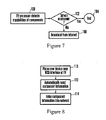
FIG. 6 shows set up logic that can be used to aid the user in setting up a home network and executed by theTV processor 18 and/orserver 54 and/or in accordance with instructions on aremovable memory store 69. - At initial TV power-on at block 88, the process moves to block 90 to discover network devices in accordance with disclosure above. Proceeding to block 92, the
TV processor 18 is automatically configured for theparticular system server 54 that is discovered atblock 90. If more than one system server is discovered the user can be prompted to select one. Atblock 94, a connections database can be created to serve as a starting point for tracking, diagnosing, and recommending future network enhancements. At block 96 a network map can be displayed in accordance with above principles. - In essence, when the TV is first taken out of the box by the user and turned on, the
TV processor 18 automatically searches for networks and other connections, e.g., Ethernets, DLNA networks, etc., and then informs the user as to what capabilities exist, showing the map on thedisplay 14. Appropriate configuration of the TV is then automatically executed, relieving the user of the sometimes confusing chore of “setting up” the home network. If no networks are detected theTV processor 18 can prompt the user to “plug in your phone line to themodem 50” or other similar message or, failing that, “call the following help line.” - The
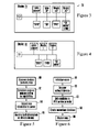
TV processor 18 can also ensure component capability maximization by detecting capabilities of components atblock 100 inFIG. 7 . The capabilities of the components may be communicated to theTV processor 18 from the components themselves, or theTV processor 18 may simply ascertain component identifications and then access a local or web-based database of capabilities corresponding to the detected component IDs. - Moving to
decision diamond 102, it is determined whether appropriate software exists on the component to fully exploit the component's capability. If so, the logic ends atstate 104, but otherwise necessary software is automatically downloaded from the Internet by theTV processor 18 and transmitted through one or more of the links shown inFIG. 1 to the relevant component. - To illustrate, suppose the
network appliance 62 shown inFIG. 1 is a wireless telephone, and theTV processor 18 determines that the phone has caller ID service capability but not the actual software to use the service. In this case, theTV processor 18 can access the Internet to download the necessary utility to the phone to enable the caller ID service. This is but one non-limiting example of theTV processor 18 determining that a capability exists on a TV network component but not the necessary software, and obtaining the necessary software from the Internet on behalf of the component. - The
RFID interface 60 of the TV can be used to not only communicate with RFID-enabledappliances 62, but also to facilitate easy network set-up. With more specificity and referring now toFIG. 8 , recognizing that attaching components to a TV network can be trying and time-consuming owing to entering lengthy strings of media access control (MAC) addresses, cryptographic capabilities and keys, etc., any of the components shown inFIG. 1 may be provided with a RFID device that contains the MAC address of the device, its cryptographic capabilities and keys, etc. Atblock 110 inFIG. 8 the component is disposed sufficiently close to theRFID interface 60 of the TV to permit the information in the RFID device of the component to be automatically transferred to theTV processor 18 atblock 112. Atblock 114, assuming the information is in order, the component can be entered into the network for, e.g., control, use, and display on one of the network maps discussed above. - While the particular TV-CENTRIC SYSTEM is herein shown and described in detail, it is to be understood that the subject matter which is encompassed by the present invention is limited only by the claims.
Claims (26)
1. A system, comprising:
a TV including a TV processor and a display; and
a user input device communicating with the processor, wherein
the processor causes a map to be presented in the display showing at least portions of a network including the TV and at least one network component and at least one communication path therebetween, wherein a user can manipulate the user input device to navigate around the map and cause content to be transmitted from a source component shown in the map to a sink component shown on the map.
2. The system of claim 1 , wherein the user input device is a TV remote control device and/or mouse and/or pointing device and one component is a home PC.
3. The system of claim 1 , wherein the map changes the appearance of at least one component icon and/or path between icons to provide visible indication of advantageous component and/or path selection for executing a user-desired task.
4. The system of claim 1 , wherein the TV processor communicates with the Internet, the TV processor uploading map information to a server on the Internet and receiving back information pertaining to components represented on the map.
5. The system of claim 4 , wherein the TV processor, upon initial energization by a user, automatically searches for network connections.
6. The system of claim 4 , wherein the server downloads information to cause the TV to automatically configure, without user interaction, at least one component represented on the map for network operability.
7. The system of claim 4 , wherein the server downloads diagnostic information to the TV and pertaining to at least one component represented on the map.
8. The system of claim 1 , wherein the network includes audio-video components and non-audio-video components selected from the group consisting of: a printer, and a scanner, the map displaying icons indicating audio-video components and icons indicating non-audio-video components.
9. The system of claim 1 , wherein the network includes audio-video components and non-audio-video components selected from the group consisting of: a printer, and a scanner, the map displaying only icons indicating audio-video components.
10. The system of claim 1 , wherein upon each energization, the TV processor discovers and/or is informed of network components and configures the map accordingly.
11. The system of claim 1 , wherein the map changes the appearance of at least one component icon and/or path between icons to provide visible indication of whether a component is energized.
12. The system of claim 8 , wherein an icon indicating an audio-video component is displayed in a first color and an icon indicating a non-audio-video component is displayed in a second color.
13. A TV-centric system comprising:
a TV including a TV processor and a display;
a user input device communicating with the processor, wherein
the processor causes a map to be presented in the display showing at least portions of a network including the TV and at least one network component and at least one communication path therebetween, wherein the map changes the appearance of at least one component icon and/or path between icons to provide visible indication of advantageous component and/or path selection for executing a user-desired task.
14. The system of claim 13 , wherein the user input device is a TV remote control device and/or mouse and/or pointing device and one component is a home PC.
15. The system of claim 13 , wherein the TV processor, upon initial energization by a user, automatically searches for network connections.
16. The system of claim 13 , wherein the network includes audio-video components and non-audio-video components selected from the group consisting of: a printer, and a scanner, the map displaying icons indicating audio-video components and icons indicating non-audio-video components;
17. The system of claim 13 , wherein the network includes audio-video components and non-audio-video components selected from the group consisting of: a printer, and a scanner, the map displaying only icons indicating audio-video components.
18. The system of claim 13 , wherein upon each energization, the TV processor discovers and/or is informed of network components.
19. The system of claim 13 , wherein the map changes the appearance of at least one component icon and/or path between icons to provide visible indication of whether a component is energized.
20. The system of claim 16 , wherein an icon indicating an audio-video component is displayed in a first color and an icon indicating a non-audio-video component is displayed in a second color.
21. The system of claim 13 , wherein an Internet server downloads information to cause the TV to automatically configure, without user interaction, at least one component represented on the map for network operability.
22. The system of claim 13 , wherein an Internet server downloads diagnostic information to the TV and pertaining to at least one component represented on the map.
23. A TV-centric system comprising:
a TV including a TV processor and a display;
a user input device communicating with the processor; and
the TV processor being connected to the Internet, the TV processor uploading network map information to a server on the Internet and receiving back information pertaining to components represented on the map.
24. The system of claim 23 , wherein the TV processor, upon initial energization by a user, automatically searches for network connections.
25. The system of claim 23 , wherein the server downloads information to cause the TV to automatically configure, without user interaction, at least one component represented on the map for network operability.
26. The system of claim 23 , wherein the server downloads diagnostic information to the TV and pertaining to at least one component represented on the map.
Priority Applications (1)
| Application Number | Priority Date | Filing Date | Title |
|---|---|---|---|
| US11/583,524 US20080098452A1 (en) | 2006-10-18 | 2006-10-18 | TV-centric system |
Applications Claiming Priority (1)
| Application Number | Priority Date | Filing Date | Title |
|---|---|---|---|
| US11/583,524 US20080098452A1 (en) | 2006-10-18 | 2006-10-18 | TV-centric system |
Publications (1)
| Publication Number | Publication Date |
|---|---|
| US20080098452A1 true US20080098452A1 (en) | 2008-04-24 |
Family
ID=39319580
Family Applications (1)
| Application Number | Title | Priority Date | Filing Date |
|---|---|---|---|
| US11/583,524 Abandoned US20080098452A1 (en) | 2006-10-18 | 2006-10-18 | TV-centric system |
Country Status (1)
| Country | Link |
|---|---|
| US (1) | US20080098452A1 (en) |
Cited By (11)
| Publication number | Priority date | Publication date | Assignee | Title |
|---|---|---|---|---|
| US20080120682A1 (en) * | 2006-11-17 | 2008-05-22 | Robert Hardacker | TV-centric system |
| US20090063978A1 (en) * | 2007-09-05 | 2009-03-05 | Sony Corporation | Network status icon in navigable toolbar |
| US20090113345A1 (en) * | 2007-10-30 | 2009-04-30 | Sony Corporation And Sony Electronics Inc. | Automatically culled cross-menu bar |
| US20100082794A1 (en) * | 2008-10-01 | 2010-04-01 | Sony Corporation | Home network visualization |
| US20140137167A1 (en) * | 2008-12-24 | 2014-05-15 | Broadcom Corporation | Remote control device transaction setup in a home network |
| US20140223503A1 (en) * | 2013-02-01 | 2014-08-07 | Ebay Inc. | Methods, Systems and Apparatus for Configuring a System of Content Access Devices |
| US20140298393A1 (en) * | 2013-03-29 | 2014-10-02 | Samsung Electronics Co., Ltd. | Display apparatus and control method thereof |
| US20150058896A1 (en) * | 2012-04-13 | 2015-02-26 | Sony Computer Entertaiment Inc. | Information processing system and media server |
| US9065879B2 (en) | 2000-10-23 | 2015-06-23 | Ebay Inc. | Methods and systems for selecting media content based on technical environment information |
| US10034060B2 (en) | 2013-03-29 | 2018-07-24 | Samsung Electronics Co., Ltd. | Display apparatus and control method thereof |
| CN109831692A (en) * | 2019-03-08 | 2019-05-31 | 陕西广茂电子科技有限责任公司 | A kind of data of set top box orientation method for pushing and system based on Wifi technology |
Citations (50)
| Publication number | Priority date | Publication date | Assignee | Title |
|---|---|---|---|---|
| US5539815A (en) * | 1995-02-24 | 1996-07-23 | At&T Corp. | Network call routing controlled by a management node |
| US5793366A (en) * | 1996-11-12 | 1998-08-11 | Sony Corporation | Graphical display of an animated data stream between devices on a bus |
| US5883621A (en) * | 1996-06-21 | 1999-03-16 | Sony Corporation | Device control with topology map in a digital network |
| US5991050A (en) * | 1994-02-18 | 1999-11-23 | Microsoft Corporation | System for transferring messages between input and output devices in a communication device |
| US6052750A (en) * | 1998-01-06 | 2000-04-18 | Sony Corporation Of Japan | Home audio/video network for generating default control parameters for devices coupled to the network, and replacing updated control parameters therewith |
| US6119162A (en) * | 1998-09-25 | 2000-09-12 | Actiontec Electronics, Inc. | Methods and apparatus for dynamic internet server selection |
| US6252886B1 (en) * | 1998-07-06 | 2001-06-26 | Sony Corporation | Bandwidth reservation |
| US6275865B1 (en) * | 1998-11-25 | 2001-08-14 | Sony Corporation Of Japan | Method and system for message dispatching in a home audio/video network |
| US20010030667A1 (en) * | 2000-04-10 | 2001-10-18 | Kelts Brett R. | Interactive display interface for information objects |
| US6363434B1 (en) * | 1999-03-30 | 2002-03-26 | Sony Corporation Of Japan | Method of managing resources within a network of consumer electronic devices |
| US20020095484A1 (en) * | 2001-01-12 | 2002-07-18 | Oscar Pagani | Method and apparatus for efficiently configuring customer premesis equipment |
| US20020103880A1 (en) * | 2001-01-26 | 2002-08-01 | David Konetski | System and method for using resources of a computer system in conjuction with a thin media client |
| US6469742B1 (en) * | 1999-04-12 | 2002-10-22 | Koninklijke Philips Electronics N.V. | Consumer electronic devices with adaptable upgrade capability |
| US20030014548A1 (en) * | 2001-06-27 | 2003-01-16 | 3Com Corporation | Method and apparatus for determining unmanaged network devices in the topology of a network |
| US20030048380A1 (en) * | 2001-09-12 | 2003-03-13 | Yuriko Tamura | Self provisioning Set-Top Box |
| US6539450B1 (en) * | 1998-11-29 | 2003-03-25 | Sony Corporation | Method and system for adjusting isochronous bandwidths on a bus |
| US20030075983A1 (en) * | 2001-05-03 | 2003-04-24 | Mitsubishi Digital Electronics America, Inc. | Control system and user interface for network of input devices |
| US6577327B1 (en) * | 1999-09-15 | 2003-06-10 | Nortel Networks Limited | System, method and graphical user interface for building virtual private networks |
| US20030158927A1 (en) * | 2002-02-21 | 2003-08-21 | Gateway, Inc. | Connected home network console |
| US20030223411A1 (en) * | 2002-05-30 | 2003-12-04 | De La Fuente Ramon | Streaming audio/video guidance in a consumer appliance |
| US6725260B1 (en) * | 1998-09-11 | 2004-04-20 | L.V. Partners, L.P. | Method and apparatus for configuring configurable equipment with configuration information received from a remote location |
| US20040098515A1 (en) * | 2000-09-06 | 2004-05-20 | Babak Rezvani | Systems and methods for the automatic registration of devices |
| US20040117788A1 (en) * | 2002-12-11 | 2004-06-17 | Jeyhan Karaoguz | Method and system for TV interface for coordinating media exchange with a media peripheral |
| US20040133657A1 (en) * | 2003-01-03 | 2004-07-08 | Broadq, Llc | Digital media system and method therefor |
| US20040177371A1 (en) * | 2003-03-07 | 2004-09-09 | Rami Caspi | System and method for integrated communications center |
| US6801507B1 (en) * | 1999-07-27 | 2004-10-05 | Samsung Electronics Co., Ltd. | Device discovery and configuration in a home network |
| US20040210450A1 (en) * | 2002-11-19 | 2004-10-21 | Michael Atencio | System architecture for self-provisoning services and method of use |
| US20040220926A1 (en) * | 2000-01-03 | 2004-11-04 | Interactual Technologies, Inc., A California Cpr[P | Personalization services for entities from multiple sources |
| US20040250039A1 (en) * | 2003-06-05 | 2004-12-09 | Hanks D. Mitchel | System and method for using swappable storage for high data content multi-source data storage |
| US20040268407A1 (en) * | 2001-09-20 | 2004-12-30 | Sparrell Carlton J | Centralized resource manager |
| US20050018697A1 (en) * | 1996-07-25 | 2005-01-27 | Hybrid Networks, Inc. | High-speed internet access system |
| US6853388B2 (en) * | 2000-02-21 | 2005-02-08 | Kabushiki Kaisha Toshiba | Network management equipment and communication path setting method |
| US20050159823A1 (en) * | 2003-11-04 | 2005-07-21 | Universal Electronics Inc. | System and methods for home appliance identification and control in a networked environment |
| US6931442B1 (en) * | 1998-09-14 | 2005-08-16 | Fujitsu Limited | Networked devices, adapters and methods which identify monitored equipment units |
| US6947048B2 (en) * | 2003-07-21 | 2005-09-20 | Sony Corporation | Method for sharing a graphics display as a resource in an embedded system |
| US6957396B2 (en) * | 2001-10-18 | 2005-10-18 | Sony Corporation | Graphic user interface for digital networks |
| US6976267B1 (en) * | 1999-04-09 | 2005-12-13 | Sony Corporation | Method and apparatus for controlling connections between devices |
| US20060026275A1 (en) * | 2004-07-27 | 2006-02-02 | Gilmour David A | Fabric network management and diagnostic tool |
| US20060026636A1 (en) * | 2004-04-30 | 2006-02-02 | Vulcan Inc. | Maintaining a graphical user interface state that is based on a selected piece of content |
| US20060117342A1 (en) * | 2004-11-30 | 2006-06-01 | Park Pyung K | Method for acquiring channel information and registering for reception of multicast based IP TV broadcasting in access network |
| US7103834B1 (en) * | 1997-06-25 | 2006-09-05 | Samsung Electronics Co., Ltd. | Method and apparatus for a home network auto-tree builder |
| US7136914B2 (en) * | 2001-08-06 | 2006-11-14 | Ricoh Company, Ltd. | System, computer program product and method for managing and controlling a local network of electronic devices |
| US7200683B1 (en) * | 1999-08-17 | 2007-04-03 | Samsung Electronics, Co., Ltd. | Device communication and control in a home network connected to an external network |
| US20070157241A1 (en) * | 2005-12-29 | 2007-07-05 | United Video Properties, Inc. | Interactive media guidance system having multiple devices |
| US20080120682A1 (en) * | 2006-11-17 | 2008-05-22 | Robert Hardacker | TV-centric system |
| US20080120683A1 (en) * | 2006-11-20 | 2008-05-22 | Milton Massey Frazier | TV-centric system |
| US20080229370A1 (en) * | 2007-03-13 | 2008-09-18 | Zustak Frederick J | TV-centric system |
| US7577906B2 (en) * | 2004-11-08 | 2009-08-18 | Microsoft Corporation | Method and system for document assembly |
| US7600227B2 (en) * | 1999-12-09 | 2009-10-06 | Microsoft Corporation | Automatic detection and installation of client peripheral devices by a server |
| US20110093903A1 (en) * | 2005-12-08 | 2011-04-21 | Lilly Huang | System and method for controlling home network devices using multicast enabled remote controls |
-
2006
- 2006-10-18 US US11/583,524 patent/US20080098452A1/en not_active Abandoned
Patent Citations (52)
| Publication number | Priority date | Publication date | Assignee | Title |
|---|---|---|---|---|
| US5991050A (en) * | 1994-02-18 | 1999-11-23 | Microsoft Corporation | System for transferring messages between input and output devices in a communication device |
| US5539815A (en) * | 1995-02-24 | 1996-07-23 | At&T Corp. | Network call routing controlled by a management node |
| US5883621A (en) * | 1996-06-21 | 1999-03-16 | Sony Corporation | Device control with topology map in a digital network |
| US20050018697A1 (en) * | 1996-07-25 | 2005-01-27 | Hybrid Networks, Inc. | High-speed internet access system |
| US5793366A (en) * | 1996-11-12 | 1998-08-11 | Sony Corporation | Graphical display of an animated data stream between devices on a bus |
| US7103834B1 (en) * | 1997-06-25 | 2006-09-05 | Samsung Electronics Co., Ltd. | Method and apparatus for a home network auto-tree builder |
| US6052750A (en) * | 1998-01-06 | 2000-04-18 | Sony Corporation Of Japan | Home audio/video network for generating default control parameters for devices coupled to the network, and replacing updated control parameters therewith |
| US6252886B1 (en) * | 1998-07-06 | 2001-06-26 | Sony Corporation | Bandwidth reservation |
| US6725260B1 (en) * | 1998-09-11 | 2004-04-20 | L.V. Partners, L.P. | Method and apparatus for configuring configurable equipment with configuration information received from a remote location |
| US6931442B1 (en) * | 1998-09-14 | 2005-08-16 | Fujitsu Limited | Networked devices, adapters and methods which identify monitored equipment units |
| US6119162A (en) * | 1998-09-25 | 2000-09-12 | Actiontec Electronics, Inc. | Methods and apparatus for dynamic internet server selection |
| US6275865B1 (en) * | 1998-11-25 | 2001-08-14 | Sony Corporation Of Japan | Method and system for message dispatching in a home audio/video network |
| US6539450B1 (en) * | 1998-11-29 | 2003-03-25 | Sony Corporation | Method and system for adjusting isochronous bandwidths on a bus |
| US6363434B1 (en) * | 1999-03-30 | 2002-03-26 | Sony Corporation Of Japan | Method of managing resources within a network of consumer electronic devices |
| US6976267B1 (en) * | 1999-04-09 | 2005-12-13 | Sony Corporation | Method and apparatus for controlling connections between devices |
| US6469742B1 (en) * | 1999-04-12 | 2002-10-22 | Koninklijke Philips Electronics N.V. | Consumer electronic devices with adaptable upgrade capability |
| US6801507B1 (en) * | 1999-07-27 | 2004-10-05 | Samsung Electronics Co., Ltd. | Device discovery and configuration in a home network |
| US7200683B1 (en) * | 1999-08-17 | 2007-04-03 | Samsung Electronics, Co., Ltd. | Device communication and control in a home network connected to an external network |
| US6577327B1 (en) * | 1999-09-15 | 2003-06-10 | Nortel Networks Limited | System, method and graphical user interface for building virtual private networks |
| US7600227B2 (en) * | 1999-12-09 | 2009-10-06 | Microsoft Corporation | Automatic detection and installation of client peripheral devices by a server |
| US20040220926A1 (en) * | 2000-01-03 | 2004-11-04 | Interactual Technologies, Inc., A California Cpr[P | Personalization services for entities from multiple sources |
| US6853388B2 (en) * | 2000-02-21 | 2005-02-08 | Kabushiki Kaisha Toshiba | Network management equipment and communication path setting method |
| US20010030667A1 (en) * | 2000-04-10 | 2001-10-18 | Kelts Brett R. | Interactive display interface for information objects |
| US20040098515A1 (en) * | 2000-09-06 | 2004-05-20 | Babak Rezvani | Systems and methods for the automatic registration of devices |
| US20020095484A1 (en) * | 2001-01-12 | 2002-07-18 | Oscar Pagani | Method and apparatus for efficiently configuring customer premesis equipment |
| US20020103880A1 (en) * | 2001-01-26 | 2002-08-01 | David Konetski | System and method for using resources of a computer system in conjuction with a thin media client |
| US20030075983A1 (en) * | 2001-05-03 | 2003-04-24 | Mitsubishi Digital Electronics America, Inc. | Control system and user interface for network of input devices |
| US20030014548A1 (en) * | 2001-06-27 | 2003-01-16 | 3Com Corporation | Method and apparatus for determining unmanaged network devices in the topology of a network |
| US7136914B2 (en) * | 2001-08-06 | 2006-11-14 | Ricoh Company, Ltd. | System, computer program product and method for managing and controlling a local network of electronic devices |
| US20030048380A1 (en) * | 2001-09-12 | 2003-03-13 | Yuriko Tamura | Self provisioning Set-Top Box |
| US20040268407A1 (en) * | 2001-09-20 | 2004-12-30 | Sparrell Carlton J | Centralized resource manager |
| US6957396B2 (en) * | 2001-10-18 | 2005-10-18 | Sony Corporation | Graphic user interface for digital networks |
| US20030158927A1 (en) * | 2002-02-21 | 2003-08-21 | Gateway, Inc. | Connected home network console |
| US20030223411A1 (en) * | 2002-05-30 | 2003-12-04 | De La Fuente Ramon | Streaming audio/video guidance in a consumer appliance |
| US20040210450A1 (en) * | 2002-11-19 | 2004-10-21 | Michael Atencio | System architecture for self-provisoning services and method of use |
| US20040117788A1 (en) * | 2002-12-11 | 2004-06-17 | Jeyhan Karaoguz | Method and system for TV interface for coordinating media exchange with a media peripheral |
| US20040133657A1 (en) * | 2003-01-03 | 2004-07-08 | Broadq, Llc | Digital media system and method therefor |
| US20040177371A1 (en) * | 2003-03-07 | 2004-09-09 | Rami Caspi | System and method for integrated communications center |
| US20040250039A1 (en) * | 2003-06-05 | 2004-12-09 | Hanks D. Mitchel | System and method for using swappable storage for high data content multi-source data storage |
| US6947048B2 (en) * | 2003-07-21 | 2005-09-20 | Sony Corporation | Method for sharing a graphics display as a resource in an embedded system |
| US20050159823A1 (en) * | 2003-11-04 | 2005-07-21 | Universal Electronics Inc. | System and methods for home appliance identification and control in a networked environment |
| US20060064720A1 (en) * | 2004-04-30 | 2006-03-23 | Vulcan Inc. | Controlling one or more media devices |
| US20060026636A1 (en) * | 2004-04-30 | 2006-02-02 | Vulcan Inc. | Maintaining a graphical user interface state that is based on a selected piece of content |
| US20060026275A1 (en) * | 2004-07-27 | 2006-02-02 | Gilmour David A | Fabric network management and diagnostic tool |
| US7577906B2 (en) * | 2004-11-08 | 2009-08-18 | Microsoft Corporation | Method and system for document assembly |
| US20060117342A1 (en) * | 2004-11-30 | 2006-06-01 | Park Pyung K | Method for acquiring channel information and registering for reception of multicast based IP TV broadcasting in access network |
| US20110093903A1 (en) * | 2005-12-08 | 2011-04-21 | Lilly Huang | System and method for controlling home network devices using multicast enabled remote controls |
| US20070157241A1 (en) * | 2005-12-29 | 2007-07-05 | United Video Properties, Inc. | Interactive media guidance system having multiple devices |
| US20080120682A1 (en) * | 2006-11-17 | 2008-05-22 | Robert Hardacker | TV-centric system |
| US20080120683A1 (en) * | 2006-11-20 | 2008-05-22 | Milton Massey Frazier | TV-centric system |
| US7577908B2 (en) * | 2006-11-20 | 2009-08-18 | Sony Corporation | TV-centric system |
| US20080229370A1 (en) * | 2007-03-13 | 2008-09-18 | Zustak Frederick J | TV-centric system |
Cited By (19)
| Publication number | Priority date | Publication date | Assignee | Title |
|---|---|---|---|---|
| US9065879B2 (en) | 2000-10-23 | 2015-06-23 | Ebay Inc. | Methods and systems for selecting media content based on technical environment information |
| US9866598B2 (en) | 2000-10-23 | 2018-01-09 | Ebay Inc. | Methods and systems to assess an ability to playback media content |
| US9571531B2 (en) | 2000-10-23 | 2017-02-14 | Ebay Inc. | Methods and systems for selecting media content based on technical environment information |
| US9319482B2 (en) | 2000-10-23 | 2016-04-19 | Ebay Inc. | Method and system for providing media content over a computer network |
| US20080120682A1 (en) * | 2006-11-17 | 2008-05-22 | Robert Hardacker | TV-centric system |
| US20090063978A1 (en) * | 2007-09-05 | 2009-03-05 | Sony Corporation | Network status icon in navigable toolbar |
| US20090113345A1 (en) * | 2007-10-30 | 2009-04-30 | Sony Corporation And Sony Electronics Inc. | Automatically culled cross-menu bar |
| US8683383B2 (en) * | 2007-10-30 | 2014-03-25 | Sony Corporation | Automatically culled cross-menu bar |
| WO2010039415A1 (en) * | 2008-10-01 | 2010-04-08 | Sony Corporation | Home network visualization |
| US20100082794A1 (en) * | 2008-10-01 | 2010-04-01 | Sony Corporation | Home network visualization |
| US9374609B2 (en) * | 2008-12-24 | 2016-06-21 | Broadcom Corporation | Remote control device transaction setup in a home network |
| US20140137167A1 (en) * | 2008-12-24 | 2014-05-15 | Broadcom Corporation | Remote control device transaction setup in a home network |
| US20150058896A1 (en) * | 2012-04-13 | 2015-02-26 | Sony Computer Entertaiment Inc. | Information processing system and media server |
| US8935734B2 (en) * | 2013-02-01 | 2015-01-13 | Ebay Inc. | Methods, systems and apparatus for configuring a system of content access devices |
| US20140223503A1 (en) * | 2013-02-01 | 2014-08-07 | Ebay Inc. | Methods, Systems and Apparatus for Configuring a System of Content Access Devices |
| US20140298393A1 (en) * | 2013-03-29 | 2014-10-02 | Samsung Electronics Co., Ltd. | Display apparatus and control method thereof |
| US10034060B2 (en) | 2013-03-29 | 2018-07-24 | Samsung Electronics Co., Ltd. | Display apparatus and control method thereof |
| US10869101B2 (en) | 2013-03-29 | 2020-12-15 | Samsung Electronics Co., Ltd. | Display apparatus and control method thereof |
| CN109831692A (en) * | 2019-03-08 | 2019-05-31 | 陕西广茂电子科技有限责任公司 | A kind of data of set top box orientation method for pushing and system based on Wifi technology |
Similar Documents
| Publication | Publication Date | Title |
|---|---|---|
| KR101299311B1 (en) | Tv-centric system | |
| US20080098452A1 (en) | TV-centric system | |
| US7577908B2 (en) | TV-centric system | |
| US20080120682A1 (en) | TV-centric system | |
| US8682262B2 (en) | Dual function device | |
| US7924168B2 (en) | Remote control system, remote commander and remote control method, apparatus to be remotely controlled, and computer system | |
| US8856273B2 (en) | Information processing device and information processing method for communication with an external device via a network | |
| AU2004302144B2 (en) | A/V system available for integrated control and method of controlling the same | |
| US7484015B2 (en) | Apparatus and method for providing improved user interface between multiple network devices | |
| US20060195553A1 (en) | Content-information management system, content-information management apparatus, content-information management method, and computer program | |
| US11516529B2 (en) | Control system for playing a data stream on a receiving device | |
| US8880695B2 (en) | Information processing apparatus and information processing method | |
| US9805132B2 (en) | Apparatus, method and system to select content from history information representing previously reproduced content | |
| KR20010085438A (en) | Information processing apparatus, method thereof, network system, record medium, and program | |
| JP2009146384A (en) | Information processing apparatus and information processing method | |
| JP2007184745A (en) | Remote control system, equipment to be remotely controlled, and computer system | |
| CN101091353A (en) | Device, system, and method for providing error information in xht network | |
| US20120023539A1 (en) | Information processing apparatus and content receiving method | |
| US20080115189A1 (en) | TV-centric system | |
| EP2686985A1 (en) | Cloud-based resource management | |
| KR100608807B1 (en) | Integrally controllable A/V system and method therefor | |
| JP3689653B2 (en) | Device control system | |
| US20080252785A1 (en) | System and method for aiding user in making correct TV connections | |
| JP2012034041A (en) | Video reproduction control apparatus and video reproduction control method |
Legal Events
| Date | Code | Title | Description |
|---|---|---|---|
| AS | Assignment |
Owner name: SONY CORPORATION, JAPAN Free format text: ASSIGNMENT OF ASSIGNORS INTEREST;ASSIGNORS:HARDACKER, ROBERT L.;ZUSTAK, FREDERICK J.;REEL/FRAME:018462/0032;SIGNING DATES FROM 20061016 TO 20061018 Owner name: SONY ELECTRONICS INC., NEW JERSEY Free format text: ASSIGNMENT OF ASSIGNORS INTEREST;ASSIGNORS:HARDACKER, ROBERT L.;ZUSTAK, FREDERICK J.;REEL/FRAME:018462/0032;SIGNING DATES FROM 20061016 TO 20061018 |
|
| STCB | Information on status: application discontinuation |
Free format text: ABANDONED -- AFTER EXAMINER'S ANSWER OR BOARD OF APPEALS DECISION |