US20080098601A1 - Tubular tapered crushable structures and manufacturing methods - Google Patents
Tubular tapered crushable structures and manufacturing methods Download PDFInfo
- Publication number
- US20080098601A1 US20080098601A1 US11/766,406 US76640607A US2008098601A1 US 20080098601 A1 US20080098601 A1 US 20080098601A1 US 76640607 A US76640607 A US 76640607A US 2008098601 A1 US2008098601 A1 US 2008098601A1
- Authority
- US
- United States
- Prior art keywords
- tubing
- tapered
- method defined
- ksi
- compression box
- Prior art date
- Legal status (The legal status is an assumption and is not a legal conclusion. Google has not performed a legal analysis and makes no representation as to the accuracy of the status listed.)
- Abandoned
Links
Images

Classifications
-
- B—PERFORMING OPERATIONS; TRANSPORTING
- B60—VEHICLES IN GENERAL
- B60R—VEHICLES, VEHICLE FITTINGS, OR VEHICLE PARTS, NOT OTHERWISE PROVIDED FOR
- B60R19/00—Wheel guards; Radiator guards, e.g. grilles; Obstruction removers; Fittings damping bouncing force in collisions
- B60R19/02—Bumpers, i.e. impact receiving or absorbing members for protecting vehicles or fending off blows from other vehicles or objects
- B60R19/24—Arrangements for mounting bumpers on vehicles
- B60R19/26—Arrangements for mounting bumpers on vehicles comprising yieldable mounting means
- B60R19/34—Arrangements for mounting bumpers on vehicles comprising yieldable mounting means destroyed upon impact, e.g. one-shot type
-
- B—PERFORMING OPERATIONS; TRANSPORTING
- B21—MECHANICAL METAL-WORKING WITHOUT ESSENTIALLY REMOVING MATERIAL; PUNCHING METAL
- B21D—WORKING OR PROCESSING OF SHEET METAL OR METAL TUBES, RODS OR PROFILES WITHOUT ESSENTIALLY REMOVING MATERIAL; PUNCHING METAL
- B21D39/00—Application of procedures in order to connect objects or parts, e.g. coating with sheet metal otherwise than by plating; Tube expanders
- B21D39/08—Tube expanders
- B21D39/20—Tube expanders with mandrels, e.g. expandable
-
- B—PERFORMING OPERATIONS; TRANSPORTING
- B21—MECHANICAL METAL-WORKING WITHOUT ESSENTIALLY REMOVING MATERIAL; PUNCHING METAL
- B21D—WORKING OR PROCESSING OF SHEET METAL OR METAL TUBES, RODS OR PROFILES WITHOUT ESSENTIALLY REMOVING MATERIAL; PUNCHING METAL
- B21D41/00—Application of procedures in order to alter the diameter of tube ends
- B21D41/04—Reducing; Closing
-
- B—PERFORMING OPERATIONS; TRANSPORTING
- B21—MECHANICAL METAL-WORKING WITHOUT ESSENTIALLY REMOVING MATERIAL; PUNCHING METAL
- B21D—WORKING OR PROCESSING OF SHEET METAL OR METAL TUBES, RODS OR PROFILES WITHOUT ESSENTIALLY REMOVING MATERIAL; PUNCHING METAL
- B21D53/00—Making other particular articles
- B21D53/88—Making other particular articles other parts for vehicles, e.g. cowlings, mudguards
-
- Y—GENERAL TAGGING OF NEW TECHNOLOGICAL DEVELOPMENTS; GENERAL TAGGING OF CROSS-SECTIONAL TECHNOLOGIES SPANNING OVER SEVERAL SECTIONS OF THE IPC; TECHNICAL SUBJECTS COVERED BY FORMER USPC CROSS-REFERENCE ART COLLECTIONS [XRACs] AND DIGESTS
- Y10—TECHNICAL SUBJECTS COVERED BY FORMER USPC
- Y10T—TECHNICAL SUBJECTS COVERED BY FORMER US CLASSIFICATION
- Y10T29/00—Metal working
- Y10T29/49—Method of mechanical manufacture
- Y10T29/49616—Structural member making
- Y10T29/49622—Vehicular structural member making
Abstract
A method includes steps of providing round tubing, providing a compression box and wedging dies, and reshaping the round tubing into a single or double-tapered rectangular tube including using the compression box to control an outside shape, while using the wedging dies to force material of the tubing outwardly toward the compression box. This arrangement minimizes material thinning. A tubular crushable structure is produced that is designed for longitudinal impact-energy-absorbing capability. The crushable structure includes a single or double-tapered rectangular tube made of material having a tensile strength of at least 40 KSI. In a narrower form the tensile strength is at least 80 KSI, though it can be 100 KSI or higher.
Description
- This application claims benefit under 35 U.S.C. § 119(e) of provisional application Ser. No. 60/863,488, filed Oct. 30, 2006, entitled TUBULAR TAPERED CRUSHABLE STRUCTURES AND MANUFACTURING METHODS.
- The present invention relates to crushable structures configured for energy absorption and energy management such as during a vehicle crash.
- Vehicle components are designed to reduce property damage and provide safety to the occupants of an impacted vehicle through energy management. This is typically accomplished by designing vehicle components for predictable and repeatable deformation. In low-speed impacts, components such as bumpers and bumper brackets are designed to absorb significant amounts of energy when impacted via deformation of these components. For higher-speed impacts, the vehicle chassis is designed to absorb energy by deforming. Side impacts also use deformable components such as sills, rocker panels, pillars and door impact beams. One main difference between the side impact components and those components located on the front or the rear of the vehicle is in how they are designed to absorb energy via deformation. The side impact components absorb energy via deformation associated with side-bending-type shape change of the components. Frontal and rear components such as bumper brackets and chassis components are designed to crush in an accordion fashion in a direction parallel to the impacting force. In frontal and rear impacts, the collision is either between a moving vehicle and a fixed object (wall, barrier, pole, tree, etc.) or between two moving vehicles. The impact energies are typically high due to speeds and crash dynamics. Chassis components must be able to deform in a predictable and repeatable manner to provide safety to the occupants and reduce property damage.
- Different types of component failure will produce different response curves and varying degrees of efficiency in terms of how the energy is absorbed. Impact energy absorption is calculated by multiplying a force of impact resistance times the impact stroke of a component. A component having a high efficiency of energy absorption is generally described as a component that absorbs a desired maximum amount of energy continuously over a desired maximum stroke distance. A tubular structure that bends over when impacted in a near axial direction has absorbed energy, but has not done so in a very efficient manner. A more efficient response would be had if the tube folded on itself in an accordion fashion. The accordion-type deformation provides the greatest amount of energy absorption within the provided package space. The final deformed piece represents the smallest packaging space of stacked material. The described innovation defined in this write-up is a crushable tubular structure that when impacted in a near axial direction, will collapse on itself in an accordion fashion. This innovative design can be scaled for small applications such as a bumper bracket or for larger applications such as a chassis component.
- The use of tubular structures for both chassis components and/or bumper brackets is nothing new. These types of tubular structures have been used on many various components throughout the vehicle. Most applications with this type of tubular structures coincide with protection from axial and near axial impacts. There are various manufacturing processes that are capable of producing tubular structures that when impacted in a near axial direction, will collapse on itself in an accordion fashion. The complexity and inherent cost associated with the manufacturing processes tend to increase as the energy management efficiency of the design increases. Manufacturing processes capable of producing tubular structural components and ranked by cost from high to low include hydroformed, clamshell designs fabricated from two stampings spot-welded together, deep-drawn stamping, simple expansion using internal mandrels, and simple rollformed tubular designs with crush initiators.
- Tubular components can be formed by hydroforming processes into complex shapes having non-uniform cross sections that vary along their length, where the non-uniform cross sections are tailored for particular needs and properties, such as for energy absorption. For example, vehicle frames often include hydroformed components. However, hydroforming processes are expensive, messy (since they involve placing a fluid within a tube and then pressurizing the fluid), and tend to require relatively long cycle times. Further, they become generally not satisfactory when higher strength materials are used, such as High-Strength-Low-Alloy (HSLA) materials, and/or Advanced-Ultra-High-Strength Steel (AUHSS) materials, since these materials are difficult to form, have low stretchability and poor formability, and tend to wear out tooling quickly.
- It is desirable to provide a crushable structure that can be made from high-strength steels, yet with reasonable cost and that will crush during an impact with excellent repeatable and predictable results. Thus, a component, and apparatus and method of manufacturing same having the aforementioned advantages and solving the aforementioned problems is desired.
- In one aspect of the present invention, a method of forming an axially crushable structure suitable for energy absorption during an axial impact includes providing a section of tubing, providing a compression box and wedging dies, and positioning the tubing in the compression box and positioning the wedging dies at least partially in the tubing. At least a portion of the tubing is reshaped into a tapered polygonal tubular shape with a non-circular cross section, including using the compression box to control an outside shape while using the wedging dies to force material of the tubing outwardly into engagement with the compression box.
- In another aspect of the present invention, a tubular crushable structure is designed for longitudinal impact-energy-absorbing capability. The crushable structure includes a polygonal tube having a tapered portion and a second non-tapered portion aligned with the tapered portion. The tube is made of material having a tensile strength of at least 40 KSI and having a substantially constant wall thickness along its entire length.
- In another aspect of the present invention, a tubular crushable structure is designed for longitudinal impact-energy-absorbing capability. The crushable structure includes a polygonal tube having a tapered polygonal portion and a non-tapered polygonal portion and having a substantially constant wall thickness along its entire length.
- These and other aspects, objects, and features of the present invention will be understood and appreciated by those skilled in the art upon studying the following specification, claims, and appended drawings.
-
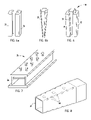
FIG. 1 is a perspective view of a raw tubing component with constant section and a finished tubular double-tapered rectangular tube component useful as a bumper crush tower. -
FIG. 2 is a perspective view of a tapered die for forming the raw tubing component. -
FIG. 3 is a perspective view of a straight section guide tube for use with the tapered die. -
FIG. 4 is a perspective view of a push collar for pushing the round tubing component into the tapered die. -
FIGS. 5 a and 5 b are perspective views of a double tapered round tube formed from the raw tubing component, and a double-tapered rectangular tube component made from the tube ofFIG. 5 a; andFIGS. 5 c and 5 d are end views ofFIGS. 51 and 5 b. -
FIG. 6 is a perspective view of a mandrel set, andFIGS. 6 a and 6 b are perspective views of the outer mandrels and inner mandrel, respectively. -
FIG. 7 is a perspective view of a compression box usable with the mandrels ofFIGS. 6 a and 6 b for the double-tapered rectangular tube component ofFIG. 5 b. -
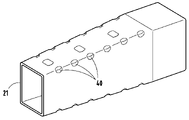
FIG. 8 is a perspective view of the finished double-tapered rectangular part with crush initiators. - The present concept combines standard low-cost manufacturing processes to produce a tube of high strength material which, upon near axial impact, produces a lower-weight part having a force/deflection response similar to that produced by the more expensive hydroformed process. The proposed inventive concepts are based on the ability to reform round tubing into a double-tapered rectangular component. Crush initiators are strategically imparted to the double-tapered rectangular component during the manufacturing process. The write-up contained here within will concentrate on the double-taper rectangular design, but it should be noted that the concept and manufacturing process can be used on any sided polygonal-shaped tubular component. It should become obvious to anyone skilled in the trades that the manufacturing processes defined within this write-up overcomes common material limitation associated with reforming a straight constant geometry shape into a double-tapered geometry of a different shape.
- The proposed inventive concepts take advantage of the benefits of and overcome the formability limitations associated with the higher physical properties of such materials as structural steel, High-Strength-Low-Alloy (HSLA) steel and Advanced Ultra-High-Strength Steel (AUHSS). In the present text, when we refer to various steels, we define structural steel as material having a tensile strength of at least about 40 KSI or higher, High-Strength-Low-Alloy (HSLA) steel as material having a tensile strength of at least about 80 KSI or higher, and Advanced Ultra-High-Strength Steel (AUHSS) as material having a tensile strength of at least about 100 KSI or higher. The higher physical properties associated with these materials provide greater energy absorption during deformation and allow for down-gauging of thickness to achieve similar performance to thicker gauge lower grade materials. The ability to down-gauge thickness and maintain performance represents a reduction in part cost and potentially a reduction in piece price. A significant drawback to using materials with higher physical properties is that materials with higher physical properties also have reduced formability as the physical properties get higher. As the yield and tensile strength increase, the elongation and in turn the formability of the material decrease. The presented inventive concepts overcome the formability limitation associated with using higher physical property materials and provide the opportunity to reduce material gauge to achieve similar performance to more formable materials.
- The following process will describe the steps necessary to overcome formability issues associated with using higher grade materials and to produce a double-tapered rectangular shaped tube from a reshaped round tube. By the term “double-tapered,” we mean a tube with a first tapered portion and a different second portion (which can be tapered or non-tapered). For illustration purposes, a round Drawn-Over Mandrel (DOM) commercially available tube will be reformed to create a double-tapered rectangular tube. The DOM tube has higher physical properties than those associated with an Electrically Resistance Welded (ERW) tube due to the additional work hardening associated with the DOM process. The DOM material used for this example had the following physical properties; Yield Strength=67,021 psi, Tensile Strength=83,775 psi, and a 0.2% Elongation=12.65%. DOM tubing with an outside diameter of 4.75 inches was used and the length of the tubing was approximately 24 inches. These physical properties are in line with structural steels and HSLA steels.
- In the original round tubular component 20 (also called “round tubing” herein) (
FIG. 1 ), the outside diameter of the DOM tubing was sized such that the circumference of the tube is slightly undersized when compared to the perimeter of the large end of the partially finished double-taperedrectangular tube 20B. The partially finished double-taperedrectangular tube 20B has a double-tapered rectangular shape, including a first rectangular portion with a first taper (or no taper), and a second rectangular portion with a different second taper. (SeeFIG. 1 .) Sizing of the circular tube outside diameter in this way will allow for some minor expansion to achieve the required perimeter of the large end of the double-tapered rectangular. The reforming and expansion process will be defined in detail in later paragraphs. The amount of expansion to go from round to rectangular should be kept to a minimum to reduce the stress on the material. Keeping expansion to a minimum is important considering the reduced formability of the higher grade of materials that are desirable for these types of deformable energy management components. - The
round DOM tubing 20 is forced into a tapered die 25 (FIG. 2 ). The die is made from hardened steel and can be produced on a lathe. The die 25 is made insections straight section 28 of the die 25 can be used to guide and support theround tubing 20 into the tapered end of the main die 25 if there are concerns associated with column bucking of theround tubing 20 as it is forced into the tapered main die 25 (FIG. 3 ). For this particular example, astraight section 28 to guide and support theround tubing 20 was not necessary and hence was not used for the DOM tubing. - A special push collar 29 (
FIG. 4 ) was developed that fit inside theround tubing 20 to transfer push loads to the outside edge of thetubing 20 as thetubing 20 was forced into the tapered die 25. Theround tube 20 was forced into the tapered die 25 (FIG. 2 ) through a distance that coincided to its desired length. At the end point of insertion into the die 25, the circumference of the smaller tapered end of partially-finishedround tube 20A was slightly undersized when compared to the final perimeter of the small end of the tapered rectangular shape in the finished part 21 (FIG. 5 ). The now taperedround tube 20A is removed from the die 25 by applying an upward force to the tapered end, forcing thetube 20A in a reverse direction back through the top of the die 25. It is noted that the described die 25 used to taper theround tube 20A is a piece of prototype tooling and a different die configuration might be more suitable for high volume production. - The tapering process may cause a length of the
original tubes 20 to grow a small amount depending on the amount of the taper. Notably, a perimeter change causes material in these hard-to-form materials to move primarily in a length direction of thetube 20. In the case of this example, thetube 20A grew approximately 0.25 inches. The amount of length growth for thetube 20A is dependent on the material type, material thickness and the amount of taper that is imparted on theraw tube 20. There can be a slight increase in the thickness of theround tube 20A, however this thickness change is not considered significant. If there is some thickness increase, the increase of thickness is most evident at the end of the round tube that experiences the greatest amount of taper. (SeeFIG. 5 , diameter “a.”) Elongation of theround tube 20A during tapering actually minimizes the amount of thickness change at the point where the maximum taper occurs on the tube. - For the example presented here, material thickness at the tapered end increased only by approximately 0.009 inches. This compares to an average material thickness in the present example of about 0.132 inches, such that the thickness change is less than 7%. It should also be noted that for the materials proposed for this concept, the variation in material thickness for as received coil stock in the present example is typically +/−0.005 inches, or about 4%. Therefore, a material thickness change of only 7% was not considered significant in the present example. For the present discussion, a material thickness change of about 7% or less along a length of a tube is considered to be a substantially constant wall thickness along the entire length of the tapered tube.
- The
tapered round tube 20A is now ready for reshaping. Thetapered round tube 20A is now ready to be reshaped to a double-taperedrectangle 20B. The reshaping process is accomplished with a combination of pure reshaping and some minor expansion. Expansion will be kept to a minimum to maintain the integrity of the wall thickness of the tube. A three-piece mandrel 30 was used to reshape theround tube 20A (FIG. 6 ). The outer twopieces mandrel 30 are shaped to represent the shorter sides of the rectangle (FIG. 6 a). Thesemandrels third part 33 of themandrel 30 is the center section (FIG. 6 b). The twomandrels center section 33 of themandrel 30. Thecenter section 33 of themandrel 30 is tapered, so as thecenter section 33 is moved down between the twomandrels mandrels rectangular mandrel 30.FIG. 6 shows a constant angle taper to thecenter section 33, but in actuality thecenter section 33 and/ormandrels - The three-
piece mandrel 30 often can not be used by itself to reshape thetapered round tube 20A to a double-tapered rectangular because of forming limitations of the desired materials. The mandrel action required to change shape from round to rectangular potentially results in significant material thinning just off the radii of the rectangular final part. The thinning may happen when the reshaping method does not allow the material to flow from one shape to another. To reshape using the internal mandrels and at the same time minimize thinning of the material, an additional fixture is desirable. A compression box 35 (FIG. 7 ) was developed to help the material flow during the reshaping operation that uses the internal three piece mandrels 31-33. Thecompression box 35 is a tapered box where three sides of the box represent the finished shape of the double-tapered rectangle. The three finished sides are the two short sides of the rectangle and one of the long sides. Thecompression box 35 does not mimic the radii of the finished shape but instead only mimics the overall position of the walls of the tapered rectangle. Thenon-fixed face 36 of thecompression box 35 is also one of the longer sides of the rectangle. Thisnon-fixed face 36 of thecompression box 35 is adjusted inward and against thetapered round tube 20A while the mandrels 31-33 are forced down the length of thetapered round tube 20A. The ability to adjust thenon-fixed face 36 of thecompression box 35 assists in the movement of material in a way that facilitates reshaping the round shape of thetube 20A to a rectangular shape of thefinished part 21 without thinning and undesirable weakening. - The
compression box 35 reduces the amount of expansion that is required to reshape the part and in turn reduces the amount of material thinning. The desire to perform a reduced amount of expansion is necessary to help size the ends of the tapered rectangle and at the same time force the repeatability of end geometries. It is noted that the detailed design of illustratedcompression box 35 illustrates only one adjustable movable surface. However, it is contemplated and envisioned that multiple sides of thecompression box 35 can be made to move or adjust. It is contemplated that those skilled in the art will understand how to do so once they understand the present concept. The use of multiple moving surfaces of thecompression box 35 would assist in the movement of material and this may be required on the reshaping of more complex polygonal shapes. The additional movable surfaces might also be necessary to increase tolerances on geometric sizing of the finished shape's surfaces and ends. - In a production mode, it is envisioned that the
compression box 35 can be adjusted with hydraulics, pneumatics, and/or servos. It is envisioned that adjustment of thenon-fixed face 36 of thecompression box 35 can be adjusted in synchronization with the position of the mandrels 31-32 as they move down the length of the round tube. This type of control would be based a closed loop control system where the location of one aspect of the process is used to control another aspect of the process. - The tapered shape of the rectangle in the
finished part 21 helps to promote an accordion style of collapse when the tube is impacted in a near axial direction. The repeatability of this type of crush is questionable due to slight variations in the load direction and the location of deformation along the length of the tube. To improve the repeatability of the crushing action, crush initiators 40 (FIG. 8 ) are typically added to the crushable parts. The type, placement, and number ofcrush initiators 40 required usually will require a development effort to identify the most optimized design. The crush initiators 40 can be added to the part preferably after the final shape has been formed. For this example, thecrush initiators 40 would be added to the double-tapered rectangular shape. - In a production mode, the
crush initiators 40 can be added using any type of stamping method, hydraulic, pneumatic, etc. Internal support will more than likely be required when thecrush initiators 40 are stamped into the part. It is envisioned that thecrush initiators 40 can be added to the part when the internal reshaping mandrels are positioned in the part. The internalouter mandrels initiators 40 are to be placed. Thecentral mandrel 33 could be backed out of the part which would allow the twooutside mandrels crush initiators 40. In a walking-beam-type production process, thecrush initiators 40 could be added to the part in a stand-alone station. It should also be noted that holes, slots, etc. . . . have been commonly used in the past as crush initiators. The manufacturing process associated with adding holes or slots is similar to the dart type of crush initiator. Both types of crush initiators will require some type of support within the tube, i.e., mandrel, die steels, etc. - The advantages of the present inventive concept include at least the following. The part can be double-tapered, which is a type of design that has proven itself to be very robust for collapsing in an accordion fashion when loaded in a near axial direction. The manufacturing “build” concept does not require a high degree of formability in the material, which allows for the use of higher grade steels. The present inventive concept expands acceptable raw steels that will work for this application, including structural steels (with tensile strength of at least 40 KSI), High-Strength-Low-Alloy (HSLA) steels (with tensile strength of at least 80 KSI) and Advanced-Ultra-High-Strength Steels (AUHSS) (with tensile strength of at least 100 KSI or more). These acceptable material grades are considerably higher than those that are acceptable for other manufacturing processes such as hydroforming and expansion. The manufacturing steps required are not unique but instead the uniqueness of this concept lies in how these manufacturing processes are combined to produce the end product. Proper material selection can result in a lighter-weight part through down-gauging material thickness and taking advantage of the higher grade materials. This can also result in a reduction of piece price.
- It is to be understood that variations and modifications can be made on the aforementioned structure without departing from the concepts of the present invention, and further it is to be understood that such concepts are intended to be covered by the following claims unless these claims by their language expressly state otherwise.
Claims (20)
1. A method of forming an axially crushable structure suitable for energy absorption during an axial impact, comprising steps of:
providing a section of tubing;
providing a compression box and wedging dies;
positioning the tubing in the compression box and the wedging dies at least partially in the tubing; and
reshaping at least a portion of the tubing into a tapered polygonal tubular shape with a non-circular cross section, including using the compression box to control an outside shape while using the wedging dies to force material of the tubing outwardly into engagement with the compression box.
2. The method defined in claim 1 , wherein the wedging dies include cooperating mandrels and a center section that, when moved axially, causes the cooperating mandrels to move apart toward the inner surfaces of the compression box.
3. The method defined in claim 2 , wherein the inner surfaces of the compression box and the cooperating mandrels include structure forming crush initiators into walls of the tubing.
4. The method defined in claim 3 , wherein the tubing is made from a material having a tensile strength of at least about 40 KSI.
5. The method defined in claim 4 , wherein the tubing is made from a material having a tensile strength of at least about 80 KSI.
6. The method defined in claim 5 , wherein the tubing is made from a material having a tensile strength of at least about 100 KSI.
7. The method defined in claim 2 , wherein at least one of the inner surfaces of the compression box is adjustable to define a different shape.
8. The method defined in claim 1 , wherein the tubing has a round cross section, and including a step of forming the round tubing into a first polygonal shape prior to the step of reshaping.
9. The method defined in claim 1 , including forming crush initiators into the tapered polygonal tubular shape to form a finished tubular polygonal crushable structure.
10. The method defined in claim 1 , wherein the step of reshaping includes forming a first portion of a length of the tubing into a tapered polygonal shape and forming a second portion of the length of the tubing into a non-tapered polygonal shape.
11. The method defined in claim 1 , wherein the step of reshaping includes forming a rectangular cross section in the tubing.
12. The method defined in claim 1 , wherein the step of providing tubing includes making the round tubing of material having a tensile strength of at least about 40 KSI.
13. The method defined in claim 1 , wherein the step of reshaping includes maintaining a thickness of material along the tubing to less than 10% variation in material thickness.
14. The method defined in claim 13 , wherein the step of reshaping includes maintaining a thickness of material along the tubing to less than about 7% variation in material thickness.
15. The method defined in claim 1 , wherein the step of reshaping includes moving material primarily in a length direction of the tubing and not in a circumferential direction of the round tube.
16. A tubular crushable structure designed for longitudinal impact-energy-absorbing capability comprising:
a polygonal tube having a tapered portion and a second non-tapered portion aligned with the tapered portion, the tube being made of a single sheet of material having a tensile strength of at least 40 KSI and having a substantially constant wall thickness along its entire length.
17. The structure defined in claim 16 , wherein the wall thickness has less than 10% variation in thickness along its length.
18. The structure defined in claim 16 , wherein the material has a tensile strength of at least 40 KSI.
19. The structure defined in claim 18 , wherein the material has a tensile strength of at least 80 KSI.
20. The structure defined in claim 16 , wherein the second portion has a circumference at least as large as the tapered portion.
Priority Applications (6)
| Application Number | Priority Date | Filing Date | Title |
|---|---|---|---|
| US11/766,406 US20080098601A1 (en) | 2006-10-30 | 2007-06-21 | Tubular tapered crushable structures and manufacturing methods |
| JP2009535391A JP2010508154A (en) | 2006-10-30 | 2007-10-22 | Crushable, tapered tubular structure and manufacturing method |
| PCT/US2007/082101 WO2008055027A2 (en) | 2006-10-30 | 2007-10-22 | Tubular tapered crushable structures and manufacturing methods |
| BRPI0718000-4A BRPI0718000A2 (en) | 2006-10-30 | 2007-10-22 | METHOD FOR FORMING AN AXIALLY SUITABLE CRUSH STRUCTURE FOR ENERGY ABSORPTION DURING AXIAL IMPACT, AND, TUBULAR CRUSH STRUCTURE |
| RU2009120550/02A RU2009120550A (en) | 2006-10-30 | 2007-10-22 | TUBULAR TAPING DESTRUCTABLE DESTRUCTIVE STRUCTURES AND METHODS FOR THEIR MANUFACTURE |
| DE112007002565T DE112007002565T5 (en) | 2006-10-30 | 2007-10-22 | Tapered crushable structures and manufacturing processes |
Applications Claiming Priority (2)
| Application Number | Priority Date | Filing Date | Title |
|---|---|---|---|
| US86348806P | 2006-10-30 | 2006-10-30 | |
| US11/766,406 US20080098601A1 (en) | 2006-10-30 | 2007-06-21 | Tubular tapered crushable structures and manufacturing methods |
Publications (1)
| Publication Number | Publication Date |
|---|---|
| US20080098601A1 true US20080098601A1 (en) | 2008-05-01 |
Family
ID=39328430
Family Applications (1)
| Application Number | Title | Priority Date | Filing Date |
|---|---|---|---|
| US11/766,406 Abandoned US20080098601A1 (en) | 2006-10-30 | 2007-06-21 | Tubular tapered crushable structures and manufacturing methods |
Country Status (6)
| Country | Link |
|---|---|
| US (1) | US20080098601A1 (en) |
| JP (1) | JP2010508154A (en) |
| BR (1) | BRPI0718000A2 (en) |
| DE (1) | DE112007002565T5 (en) |
| RU (1) | RU2009120550A (en) |
| WO (1) | WO2008055027A2 (en) |
Cited By (39)
| Publication number | Priority date | Publication date | Assignee | Title |
|---|---|---|---|---|
| US20080054655A1 (en) * | 2006-08-31 | 2008-03-06 | Mazda Motor Corporation | Vehicle bumper structure |
| US20080169660A1 (en) * | 2007-01-11 | 2008-07-17 | Ford Motor Company | Tunable inner fender structure |
| US20080169681A1 (en) * | 2007-01-11 | 2008-07-17 | Ford Motor Company | Vehicle having an interlocking floor assembly |
| US20080168644A1 (en) * | 2007-01-11 | 2008-07-17 | Ford Motor Company | Method of manufacturing a vehicle |
| US20080169677A1 (en) * | 2007-01-11 | 2008-07-17 | Ford Motor Company | Vehicle body structure |
| US20080201952A1 (en) * | 2007-01-11 | 2008-08-28 | Ford Motor Company | Method of manufacturing a vehicle |
| US20090001737A1 (en) * | 2006-01-24 | 2009-01-01 | Per Salomonsson | Crash Box for a Vehicle |
| US20090085362A1 (en) * | 2007-10-01 | 2009-04-02 | Mazda Motor Corporation | Vehicle structure for automobile |
| US20100066124A1 (en) * | 2008-09-18 | 2010-03-18 | Mazda Motor Corporation | Vehicle body structure |
| US20110309655A1 (en) * | 2009-02-26 | 2011-12-22 | Toyota Jidosha Kabushiki Kaisha | Vehicle front structure |
| US8123284B2 (en) | 2007-01-11 | 2012-02-28 | Ford Motor Company | Vehicle body component and mating feature |
| US20130076070A1 (en) * | 2011-09-27 | 2013-03-28 | Honda Motor Co., Ltd | Light-load absorbing structure |
| US20130300138A1 (en) * | 2010-09-28 | 2013-11-14 | Magna International Inc. | Scalable Crush Can For Vehicle |
| US20140034435A1 (en) * | 2011-03-28 | 2014-02-06 | Jfe Steel Corporation | Shock-absorbing member |
| US20140239671A1 (en) * | 2011-10-25 | 2014-08-28 | Toyota Jidosha Kabushiki Kaisha | Framework member |
| US9174678B2 (en) * | 2008-09-19 | 2015-11-03 | Ford Global Technologies, Llc | Twelve-cornered strengthening member |
| US9187127B2 (en) | 2008-09-19 | 2015-11-17 | Ford Global Technologies, Llc | Twelve-cornered strengthening member, assemblies including a twelve-cornered strengthening member, and methods of manufacturing and joining the same |
| CN105333295A (en) * | 2015-11-27 | 2016-02-17 | 上海迪诺克新材料科技有限公司 | Carbon fiber unequal-wall-thickness round tube |
| US20160083013A1 (en) * | 2014-09-19 | 2016-03-24 | Toyota Jidosha Kabushiki Kaisha | Vehicle body front section structure |
| US20160121830A1 (en) * | 2014-10-31 | 2016-05-05 | Benteler Automobil Technik Gmbh | Crashbox for a bumper system of a motor vehicle |
| US9403498B2 (en) | 2013-03-20 | 2016-08-02 | Shiloh Industries, Inc. | Energy absorbing assembly for vehicle |
| US9533710B2 (en) | 2008-09-19 | 2017-01-03 | Ford Global Technologies, Llc | Twelve-cornered strengthening member |
| US9789906B1 (en) | 2016-03-23 | 2017-10-17 | Ford Global Technologies, Llc | Twenty-eight-cornered strengthening member for vehicles |
| US9889887B2 (en) | 2016-01-20 | 2018-02-13 | Ford Global Technologies, Llc | Twelve-cornered strengthening member for a vehicle with straight and curved sides and an optimized straight side length to curved side radius ratio |
| US20180065678A1 (en) * | 2016-09-07 | 2018-03-08 | Thunder Power New Energy Vehicle Development Company Limited | Lateral energy absorption system |
| US9944323B2 (en) | 2015-10-27 | 2018-04-17 | Ford Global Technologies, Llc | Twenty-four-cornered strengthening member for vehicles |
| US10220881B2 (en) | 2016-08-26 | 2019-03-05 | Ford Global Technologies, Llc | Cellular structures with fourteen-cornered cells |
| US10279842B2 (en) | 2016-08-30 | 2019-05-07 | Ford Global Technologies, Llc | Twenty-eight-cornered strengthening member for vehicles |
| US10300947B2 (en) | 2016-08-30 | 2019-05-28 | Ford Global Technologies, Llc | Twenty-eight-cornered strengthening member for vehicles |
| US10315698B2 (en) | 2015-06-24 | 2019-06-11 | Ford Global Technologies, Llc | Sixteen-cornered strengthening member for vehicles |
| US10393315B2 (en) | 2016-04-26 | 2019-08-27 | Ford Global Technologies, Llc | Cellular structures with twelve-cornered cells |
| US10429006B2 (en) | 2016-10-12 | 2019-10-01 | Ford Global Technologies, Llc | Cellular structures with twelve-cornered cells |
| US10473177B2 (en) | 2016-08-23 | 2019-11-12 | Ford Global Technologies, Llc | Cellular structures with sixteen-cornered cells |
| US10647358B2 (en) | 2015-08-28 | 2020-05-12 | Honda Motor Co., Ltd. | Casting, hollow interconnecting member for connecting vehicular frame members, and vehicular frame assembly including hollow interconnecting member |
| US10704638B2 (en) | 2016-04-26 | 2020-07-07 | Ford Global Technologies, Llc | Cellular structures with twelve-cornered cells |
| US10766536B2 (en) | 2016-09-07 | 2020-09-08 | Thunder Power New Energy Vehicle Development Company Limited | Lateral energy absorption system |
| US11008050B2 (en) | 2016-12-30 | 2021-05-18 | Sabic Global Technologies B.V. | Hybrid structures and methods of making the same |
| US11292522B2 (en) | 2019-12-04 | 2022-04-05 | Ford Global Technologies, Llc | Splayed front horns for vehicle frames |
| US11603142B2 (en) | 2014-06-16 | 2023-03-14 | Sabic Global Technologies B.V. | Structural body of a vehicle having an energy absorbing device and a method of forming the energy absorbing device |
Families Citing this family (4)
| Publication number | Priority date | Publication date | Assignee | Title |
|---|---|---|---|---|
| JP6123403B2 (en) * | 2012-05-16 | 2017-05-10 | 新日鐵住金株式会社 | Vehicle framework member structure with excellent crash resistance performance and collision performance calculation method for vehicle framework member structure |
| KR101359096B1 (en) | 2012-06-27 | 2014-02-06 | 주식회사 포스코 | Crash device for vehicle |
| JP5742033B2 (en) * | 2012-08-06 | 2015-07-01 | 新吾 宮城 | Method of reducing diameter of steel pipe end and jig for reducing diameter and mold used therefor |
| CN109070822B (en) * | 2016-02-03 | 2022-04-08 | 法拉第未来公司 | Tapered crush-resistant tank for vehicle |
Citations (30)
| Publication number | Priority date | Publication date | Assignee | Title |
|---|---|---|---|---|
| US1922716A (en) * | 1932-08-31 | 1933-08-15 | Robinett Richard Andrew | Method of expanding alpha flattened paper roll |
| US2739376A (en) * | 1952-06-14 | 1956-03-27 | Smith Corp A O | Method of making draft gear housing |
| US2800943A (en) * | 1955-05-02 | 1957-07-30 | Western Electric Co | Apparatus for flaring wave guides |
| US3254521A (en) * | 1962-02-23 | 1966-06-07 | Wallace Expanding Machines | Apparatus for forming metallic sheet members |
| US3266285A (en) * | 1962-01-26 | 1966-08-16 | Jensen Erling | Production of tubing |
| US3296852A (en) * | 1963-11-29 | 1967-01-10 | Western Electric Co | Metal forming press |
| US3459028A (en) * | 1965-10-08 | 1969-08-05 | Inland Steel Co | Method and apparatus for making a side wall for a prismatic container |
| US3759203A (en) * | 1970-12-30 | 1973-09-18 | Continental Can Co | Container shaping apparatus |
| US4776196A (en) * | 1987-07-14 | 1988-10-11 | Ti Automotive Division Of Ti Canada Inc. | Process and apparatus for forming flanged ends on tubular workpieces |
| US4901557A (en) * | 1987-07-07 | 1990-02-20 | Elpatronic Ag | Method and apparatus for the production of frusto-pyramidal can bodies |
| US5231863A (en) * | 1992-04-24 | 1993-08-03 | General Electric Company | Mandrel loading method and apparatus in a thermal sizing-annealing process |
| US5727414A (en) * | 1995-06-07 | 1998-03-17 | American National Can Company | Method for reshaping a container |
| US5855137A (en) * | 1997-10-01 | 1999-01-05 | General Motors Corporation | Method of manufacturing a reservoir tube |
| US5876078A (en) * | 1997-01-21 | 1999-03-02 | Ford Global Technologies, Inc. | Bumper and front rail assembly for vehicle |
| US5913565A (en) * | 1995-09-22 | 1999-06-22 | Nissan Motor | Vehicle member |
| US6174009B1 (en) * | 1998-10-09 | 2001-01-16 | Shape Corporation | Bumper construction including self-orienting support towers providing consistent energy absorption on impact |
| US6406088B1 (en) * | 1998-11-26 | 2002-06-18 | Lotus Cars Limited | Crash rail for a vehicle |
| US6439650B2 (en) * | 1999-12-08 | 2002-08-27 | Daimlerchrysler Ag | Transverse-member module for a front or rear side end region of a motor vehicle and method of making same |
| US6588830B1 (en) * | 2002-07-01 | 2003-07-08 | Daimlerchrysler Corporation | Energy absorbing frame rail tip |
| US6651477B2 (en) * | 1998-08-07 | 2003-11-25 | Gkn Autostructures Limited | Process for forming tubular components |
| US6752451B2 (en) * | 2001-03-27 | 2004-06-22 | Nippon Steel Corporation | Strengthening member for automobile |
| US20040221639A1 (en) * | 2003-05-06 | 2004-11-11 | Daniel Woo | Coining holographic images into contoured surfaces on hard temper metal products |
| US6820924B2 (en) * | 2003-01-13 | 2004-11-23 | Ford Global Technologies, Llc | Method of improving impact absorbing and deformation control characteristics of vehicle components |
| US20050151394A1 (en) * | 2002-02-28 | 2005-07-14 | Axel Grueneklee | Supporting structure for vehicles, made of hollow steel profiles |
| US6948749B2 (en) * | 2004-01-26 | 2005-09-27 | Trim Trends Co., Llc | Cross member for vehicle bumper bar and method for making same |
| US20060096099A1 (en) * | 2003-05-08 | 2006-05-11 | Noble Metal Processing, Inc. | Automotive crush tip and method of manufacturing |
| US20060202493A1 (en) * | 2003-07-28 | 2006-09-14 | Kenji Tamura | Cash energy absorption member |
| US20060237976A1 (en) * | 2005-04-20 | 2006-10-26 | Shape Corporation | Crushable structure manufactured from mechanical expansion |
| US7257982B2 (en) * | 2004-09-21 | 2007-08-21 | Hwashin Co., Ltd. | Apparatus for forming a beam member used as a torsion beam for the rear wheel suspension of an automobile |
| US7568286B2 (en) * | 2001-08-22 | 2009-08-04 | Meritor Heavy Vehicle Technology, Llc | Method of forming a tubular axle |
-
2007
- 2007-06-21 US US11/766,406 patent/US20080098601A1/en not_active Abandoned
- 2007-10-22 JP JP2009535391A patent/JP2010508154A/en not_active Withdrawn
- 2007-10-22 DE DE112007002565T patent/DE112007002565T5/en not_active Withdrawn
- 2007-10-22 WO PCT/US2007/082101 patent/WO2008055027A2/en active Application Filing
- 2007-10-22 RU RU2009120550/02A patent/RU2009120550A/en not_active Application Discontinuation
- 2007-10-22 BR BRPI0718000-4A patent/BRPI0718000A2/en not_active Application Discontinuation
Patent Citations (31)
| Publication number | Priority date | Publication date | Assignee | Title |
|---|---|---|---|---|
| US1922716A (en) * | 1932-08-31 | 1933-08-15 | Robinett Richard Andrew | Method of expanding alpha flattened paper roll |
| US2739376A (en) * | 1952-06-14 | 1956-03-27 | Smith Corp A O | Method of making draft gear housing |
| US2800943A (en) * | 1955-05-02 | 1957-07-30 | Western Electric Co | Apparatus for flaring wave guides |
| US3266285A (en) * | 1962-01-26 | 1966-08-16 | Jensen Erling | Production of tubing |
| US3254521A (en) * | 1962-02-23 | 1966-06-07 | Wallace Expanding Machines | Apparatus for forming metallic sheet members |
| US3296852A (en) * | 1963-11-29 | 1967-01-10 | Western Electric Co | Metal forming press |
| US3459028A (en) * | 1965-10-08 | 1969-08-05 | Inland Steel Co | Method and apparatus for making a side wall for a prismatic container |
| US3759203A (en) * | 1970-12-30 | 1973-09-18 | Continental Can Co | Container shaping apparatus |
| US4901557A (en) * | 1987-07-07 | 1990-02-20 | Elpatronic Ag | Method and apparatus for the production of frusto-pyramidal can bodies |
| US4776196A (en) * | 1987-07-14 | 1988-10-11 | Ti Automotive Division Of Ti Canada Inc. | Process and apparatus for forming flanged ends on tubular workpieces |
| US5231863A (en) * | 1992-04-24 | 1993-08-03 | General Electric Company | Mandrel loading method and apparatus in a thermal sizing-annealing process |
| US5727414A (en) * | 1995-06-07 | 1998-03-17 | American National Can Company | Method for reshaping a container |
| US5913565A (en) * | 1995-09-22 | 1999-06-22 | Nissan Motor | Vehicle member |
| US5876077A (en) * | 1997-01-21 | 1999-03-02 | Ford Global Technologies, Inc. | Bumper and front rail assembly for vehicle |
| US5876078A (en) * | 1997-01-21 | 1999-03-02 | Ford Global Technologies, Inc. | Bumper and front rail assembly for vehicle |
| US5855137A (en) * | 1997-10-01 | 1999-01-05 | General Motors Corporation | Method of manufacturing a reservoir tube |
| US6651477B2 (en) * | 1998-08-07 | 2003-11-25 | Gkn Autostructures Limited | Process for forming tubular components |
| US6174009B1 (en) * | 1998-10-09 | 2001-01-16 | Shape Corporation | Bumper construction including self-orienting support towers providing consistent energy absorption on impact |
| US6406088B1 (en) * | 1998-11-26 | 2002-06-18 | Lotus Cars Limited | Crash rail for a vehicle |
| US6439650B2 (en) * | 1999-12-08 | 2002-08-27 | Daimlerchrysler Ag | Transverse-member module for a front or rear side end region of a motor vehicle and method of making same |
| US6752451B2 (en) * | 2001-03-27 | 2004-06-22 | Nippon Steel Corporation | Strengthening member for automobile |
| US7568286B2 (en) * | 2001-08-22 | 2009-08-04 | Meritor Heavy Vehicle Technology, Llc | Method of forming a tubular axle |
| US20050151394A1 (en) * | 2002-02-28 | 2005-07-14 | Axel Grueneklee | Supporting structure for vehicles, made of hollow steel profiles |
| US6588830B1 (en) * | 2002-07-01 | 2003-07-08 | Daimlerchrysler Corporation | Energy absorbing frame rail tip |
| US6820924B2 (en) * | 2003-01-13 | 2004-11-23 | Ford Global Technologies, Llc | Method of improving impact absorbing and deformation control characteristics of vehicle components |
| US20040221639A1 (en) * | 2003-05-06 | 2004-11-11 | Daniel Woo | Coining holographic images into contoured surfaces on hard temper metal products |
| US20060096099A1 (en) * | 2003-05-08 | 2006-05-11 | Noble Metal Processing, Inc. | Automotive crush tip and method of manufacturing |
| US20060202493A1 (en) * | 2003-07-28 | 2006-09-14 | Kenji Tamura | Cash energy absorption member |
| US6948749B2 (en) * | 2004-01-26 | 2005-09-27 | Trim Trends Co., Llc | Cross member for vehicle bumper bar and method for making same |
| US7257982B2 (en) * | 2004-09-21 | 2007-08-21 | Hwashin Co., Ltd. | Apparatus for forming a beam member used as a torsion beam for the rear wheel suspension of an automobile |
| US20060237976A1 (en) * | 2005-04-20 | 2006-10-26 | Shape Corporation | Crushable structure manufactured from mechanical expansion |
Cited By (64)
| Publication number | Priority date | Publication date | Assignee | Title |
|---|---|---|---|---|
| US20090001737A1 (en) * | 2006-01-24 | 2009-01-01 | Per Salomonsson | Crash Box for a Vehicle |
| US7871122B2 (en) * | 2006-01-24 | 2011-01-18 | Gestamp Hardtech Ab | Crash box for a vehicle |
| US20080054655A1 (en) * | 2006-08-31 | 2008-03-06 | Mazda Motor Corporation | Vehicle bumper structure |
| US8662546B2 (en) * | 2006-08-31 | 2014-03-04 | Mazda Motor Corporation | Vehicle bumper structure |
| US8317964B2 (en) | 2007-01-11 | 2012-11-27 | Ford Motor Company | Method of manufacturing a vehicle |
| US7798560B2 (en) | 2007-01-11 | 2010-09-21 | Ford Motor Company | Vehicle body structure |
| US20080169677A1 (en) * | 2007-01-11 | 2008-07-17 | Ford Motor Company | Vehicle body structure |
| US20080201952A1 (en) * | 2007-01-11 | 2008-08-28 | Ford Motor Company | Method of manufacturing a vehicle |
| US7591502B2 (en) * | 2007-01-11 | 2009-09-22 | Ford Motor Company | Tunable inner fender structure |
| US7677649B2 (en) | 2007-01-11 | 2010-03-16 | Ford Motor Company | Vehicle having an interlocking floor assembly |
| US8123284B2 (en) | 2007-01-11 | 2012-02-28 | Ford Motor Company | Vehicle body component and mating feature |
| US20080169681A1 (en) * | 2007-01-11 | 2008-07-17 | Ford Motor Company | Vehicle having an interlocking floor assembly |
| US7849601B2 (en) | 2007-01-11 | 2010-12-14 | Ford Motor Company | Method of manufacturing a vehicle |
| US20080168644A1 (en) * | 2007-01-11 | 2008-07-17 | Ford Motor Company | Method of manufacturing a vehicle |
| US20080169660A1 (en) * | 2007-01-11 | 2008-07-17 | Ford Motor Company | Tunable inner fender structure |
| US7926865B2 (en) * | 2007-10-01 | 2011-04-19 | Mazda Motor Corporation | Vehicle structure for automobile |
| US20090085362A1 (en) * | 2007-10-01 | 2009-04-02 | Mazda Motor Corporation | Vehicle structure for automobile |
| US20100066124A1 (en) * | 2008-09-18 | 2010-03-18 | Mazda Motor Corporation | Vehicle body structure |
| US8210601B2 (en) * | 2008-09-18 | 2012-07-03 | Mazda Motor Corporation | Vehicle body structure |
| US9187127B2 (en) | 2008-09-19 | 2015-11-17 | Ford Global Technologies, Llc | Twelve-cornered strengthening member, assemblies including a twelve-cornered strengthening member, and methods of manufacturing and joining the same |
| US10611409B2 (en) | 2008-09-19 | 2020-04-07 | Ford Global Technologies, Llc | Twelve-cornered strengthening member |
| US9845112B2 (en) | 2008-09-19 | 2017-12-19 | Ford Global Technologies, Llc | Twelve-cornered strengthening member, assemblies including a twelve-cornered strengthening member, and methods of manufacturing and joining the same |
| US9533710B2 (en) | 2008-09-19 | 2017-01-03 | Ford Global Technologies, Llc | Twelve-cornered strengthening member |
| US20180099696A1 (en) * | 2008-09-19 | 2018-04-12 | Ford Global Technologies, Llc | Twelve-cornered strengthening member |
| US9840281B2 (en) | 2008-09-19 | 2017-12-12 | Ford Global Technologies, Llc | Twelve-cornered strengthening member |
| US9174678B2 (en) * | 2008-09-19 | 2015-11-03 | Ford Global Technologies, Llc | Twelve-cornered strengthening member |
| US20110309655A1 (en) * | 2009-02-26 | 2011-12-22 | Toyota Jidosha Kabushiki Kaisha | Vehicle front structure |
| US8585129B2 (en) * | 2009-02-26 | 2013-11-19 | Toyota Jidosha Kabushiki Kaisha | Vehicle front structure |
| US9079553B2 (en) * | 2010-09-28 | 2015-07-14 | Magna International Inc. | Scalable crush can for vehicle |
| US20130300138A1 (en) * | 2010-09-28 | 2013-11-14 | Magna International Inc. | Scalable Crush Can For Vehicle |
| US9505362B2 (en) * | 2011-03-28 | 2016-11-29 | Jfe Steel Corporation | Shock-absorbing member |
| US20140034435A1 (en) * | 2011-03-28 | 2014-02-06 | Jfe Steel Corporation | Shock-absorbing member |
| US8857897B2 (en) * | 2011-09-27 | 2014-10-14 | Honda Motor Co., Ltd. | Light-load absorbing structure |
| US20130076070A1 (en) * | 2011-09-27 | 2013-03-28 | Honda Motor Co., Ltd | Light-load absorbing structure |
| US9145170B2 (en) * | 2011-10-25 | 2015-09-29 | Toyota Jidosha Kabushiki Kaisha | Framework member |
| US20140239671A1 (en) * | 2011-10-25 | 2014-08-28 | Toyota Jidosha Kabushiki Kaisha | Framework member |
| US9403498B2 (en) | 2013-03-20 | 2016-08-02 | Shiloh Industries, Inc. | Energy absorbing assembly for vehicle |
| US11603142B2 (en) | 2014-06-16 | 2023-03-14 | Sabic Global Technologies B.V. | Structural body of a vehicle having an energy absorbing device and a method of forming the energy absorbing device |
| US20160083013A1 (en) * | 2014-09-19 | 2016-03-24 | Toyota Jidosha Kabushiki Kaisha | Vehicle body front section structure |
| US9422004B2 (en) * | 2014-09-19 | 2016-08-23 | Toyota Jidosha Kabushiki Kaisha | Vehicle body front section structure |
| US9663051B2 (en) * | 2014-10-31 | 2017-05-30 | Benteler Automobiltechnik Gmbh | Crashbox for a bumper system of a motor vehicle |
| US20160121830A1 (en) * | 2014-10-31 | 2016-05-05 | Benteler Automobil Technik Gmbh | Crashbox for a bumper system of a motor vehicle |
| US10315698B2 (en) | 2015-06-24 | 2019-06-11 | Ford Global Technologies, Llc | Sixteen-cornered strengthening member for vehicles |
| US11358644B2 (en) | 2015-08-28 | 2022-06-14 | Honda Motor Co., Ltd. | Casting, hollow interconnecting member for connecting vehicular frame members, and vehicular frame assembly including hollow interconnecting member |
| US10647358B2 (en) | 2015-08-28 | 2020-05-12 | Honda Motor Co., Ltd. | Casting, hollow interconnecting member for connecting vehicular frame members, and vehicular frame assembly including hollow interconnecting member |
| US9944323B2 (en) | 2015-10-27 | 2018-04-17 | Ford Global Technologies, Llc | Twenty-four-cornered strengthening member for vehicles |
| CN105333295A (en) * | 2015-11-27 | 2016-02-17 | 上海迪诺克新材料科技有限公司 | Carbon fiber unequal-wall-thickness round tube |
| US9889887B2 (en) | 2016-01-20 | 2018-02-13 | Ford Global Technologies, Llc | Twelve-cornered strengthening member for a vehicle with straight and curved sides and an optimized straight side length to curved side radius ratio |
| US9789906B1 (en) | 2016-03-23 | 2017-10-17 | Ford Global Technologies, Llc | Twenty-eight-cornered strengthening member for vehicles |
| US10948000B2 (en) | 2016-04-26 | 2021-03-16 | Ford Global Technologies, Llc | Cellular structures with twelve-cornered cells |
| US10393315B2 (en) | 2016-04-26 | 2019-08-27 | Ford Global Technologies, Llc | Cellular structures with twelve-cornered cells |
| US10704638B2 (en) | 2016-04-26 | 2020-07-07 | Ford Global Technologies, Llc | Cellular structures with twelve-cornered cells |
| US10473177B2 (en) | 2016-08-23 | 2019-11-12 | Ford Global Technologies, Llc | Cellular structures with sixteen-cornered cells |
| US10220881B2 (en) | 2016-08-26 | 2019-03-05 | Ford Global Technologies, Llc | Cellular structures with fourteen-cornered cells |
| US10300947B2 (en) | 2016-08-30 | 2019-05-28 | Ford Global Technologies, Llc | Twenty-eight-cornered strengthening member for vehicles |
| US10538271B2 (en) | 2016-08-30 | 2020-01-21 | Ford Global Technologies, Llc | Twenty-eight-cornered strengthening member for vehicles |
| US10279842B2 (en) | 2016-08-30 | 2019-05-07 | Ford Global Technologies, Llc | Twenty-eight-cornered strengthening member for vehicles |
| US10766536B2 (en) | 2016-09-07 | 2020-09-08 | Thunder Power New Energy Vehicle Development Company Limited | Lateral energy absorption system |
| US10336373B2 (en) * | 2016-09-07 | 2019-07-02 | Thunder Power New Energy Vehicle Development Company Limited | Lateral energy absorption system |
| US20180065678A1 (en) * | 2016-09-07 | 2018-03-08 | Thunder Power New Energy Vehicle Development Company Limited | Lateral energy absorption system |
| US10429006B2 (en) | 2016-10-12 | 2019-10-01 | Ford Global Technologies, Llc | Cellular structures with twelve-cornered cells |
| US11008050B2 (en) | 2016-12-30 | 2021-05-18 | Sabic Global Technologies B.V. | Hybrid structures and methods of making the same |
| US11292522B2 (en) | 2019-12-04 | 2022-04-05 | Ford Global Technologies, Llc | Splayed front horns for vehicle frames |
| US11807303B2 (en) | 2019-12-04 | 2023-11-07 | Ford Global Technologies, Llc | Splayed front horns for vehicle frames |
Also Published As
| Publication number | Publication date |
|---|---|
| BRPI0718000A2 (en) | 2013-11-19 |
| WO2008055027A3 (en) | 2008-11-06 |
| WO2008055027A2 (en) | 2008-05-08 |
| DE112007002565T5 (en) | 2009-10-01 |
| JP2010508154A (en) | 2010-03-18 |
| RU2009120550A (en) | 2010-12-10 |
Similar Documents
| Publication | Publication Date | Title |
|---|---|---|
| US20080098601A1 (en) | Tubular tapered crushable structures and manufacturing methods | |
| US7617916B2 (en) | Tapered crushable polygonal structure | |
| US20060237976A1 (en) | Crushable structure manufactured from mechanical expansion | |
| EP1293415B1 (en) | Automobile frame member | |
| CN102632854B (en) | Crash can made of aluminum-alloy casting | |
| JP4966857B2 (en) | Energy management cylinder, method of manufacturing the same, and energy management mat | |
| US6216509B1 (en) | Hydroformed tubular member and method of hydroforming tubular members | |
| JP5042904B2 (en) | Bumper reinforcement for vehicles | |
| EP1714834A1 (en) | Impact absorbing device of vehicle | |
| JP2008504162A (en) | Vehicle bumper beam | |
| JP6551523B2 (en) | Press processing method | |
| US3577621A (en) | Stretch method for making a tubular product | |
| CA2926774A1 (en) | Crash box and method for producing the same | |
| CA2526117A1 (en) | Tubular axle housing assembly with varying wall thickness | |
| US8826712B1 (en) | Pressure sequence process for hydro-forming an extruded structural tube | |
| EP1854675B1 (en) | Motor vehicle bumper beam system | |
| CN101529118A (en) | Tubular tapered crushable structures and manufacturing methods | |
| Shin et al. | Prototype tryout and die design for automotive parts using welded blank hydroforming | |
| EP1654149B1 (en) | Vehicle frame having energy management system and method for making same | |
| JP2009509775A (en) | Continuous process for roll forming stamped sheets | |
| JP2008189311A (en) | Load receiving article for vehicle | |
| CN111319577B (en) | Energy-absorbing box with hydroforming structure | |
| Morphy | Hydroforming high strength steel tube for automotive structural applications using expansion | |
| US9283602B2 (en) | Process and apparatus for producing a hollow body, and hollow body | |
| Nikhare | Effect of Thickness on Tube Deformation Mechanics During Low Pressure Tube Hydroforming Process Sequence Variation |
Legal Events
| Date | Code | Title | Description |
|---|---|---|---|
| AS | Assignment |
Owner name: SHAPE CORPORATION, MICHIGAN Free format text: ASSIGNMENT OF ASSIGNORS INTEREST;ASSIGNORS:HEINZ, RICHARD D.;LYONS, BRUCE W.;IGNAFOL, GUY M.;AND OTHERS;REEL/FRAME:019464/0890;SIGNING DATES FROM 20070609 TO 20070618 |
|
| STCB | Information on status: application discontinuation |
Free format text: ABANDONED -- FAILURE TO RESPOND TO AN OFFICE ACTION |