US20080098701A1 - Air cleaner element holding structure - Google Patents
Air cleaner element holding structure Download PDFInfo
- Publication number
- US20080098701A1 US20080098701A1 US11/877,286 US87728607A US2008098701A1 US 20080098701 A1 US20080098701 A1 US 20080098701A1 US 87728607 A US87728607 A US 87728607A US 2008098701 A1 US2008098701 A1 US 2008098701A1
- Authority
- US
- United States
- Prior art keywords
- air cleaner
- support plates
- case
- holder
- air
- Prior art date
- Legal status (The legal status is an assumption and is not a legal conclusion. Google has not performed a legal analysis and makes no representation as to the accuracy of the status listed.)
- Granted
Links
Images

Classifications
-
- F—MECHANICAL ENGINEERING; LIGHTING; HEATING; WEAPONS; BLASTING
- F02—COMBUSTION ENGINES; HOT-GAS OR COMBUSTION-PRODUCT ENGINE PLANTS
- F02M—SUPPLYING COMBUSTION ENGINES IN GENERAL WITH COMBUSTIBLE MIXTURES OR CONSTITUENTS THEREOF
- F02M35/00—Combustion-air cleaners, air intakes, intake silencers, or induction systems specially adapted for, or arranged on, internal-combustion engines
- F02M35/02—Air cleaners
- F02M35/024—Air cleaners using filters, e.g. moistened
Definitions
- the present invention relates to an air cleaner element holding structure.
- the present invention relates to an element holding structure for an air cleaner device for use in filtering an intake air for an engine of a vehicle.
- the air cleaner element has a cylindrical shape, and the intake duct is allowed to face the outer circumferential side of the element in the air cleaner case, so that the outer circumferential side of the element is defined as a dirty side (intake air upstream side) and the inner circumferential side thereof is defined as a clean side (intake air downstream side), and the air cleaner element is held in the air cleaner case through the element holder arranged on the inner circumferential side of the element (e.g., JP-A No. S62-074790).
- the element holder also functions as a flame trap (spark arrester) by which flame (backfire) and the like from an engine are prevented from reaching the air cleaner element.
- the inner circumferential side of the air cleaner element in a cylindrical shape is defined as a dirty side and the outer circumferential side thereof is defined as a clean side.
- the outer circumferential side thereof is defined as a clean side.
- one object of the present invention is to reduce the number of components and steps for maintenance in an element holding structure for an air cleaner device in which the inner circumferential side of a wet and cylindrical air cleaner element is defined as a dirty side and the outer circumferential side thereof is defined as a clean side.
- One aspect of the present invention provides an air cleaner element holding structure for an air cleaner device (for example, an air cleaner device 11 in the embodiment) in which a wet and cylindrical air cleaner element (for example, an air cleaner element 61 in the embodiment) and an element holder (for example, an element holder 66 in the embodiment) for supporting the element are accommodated in an air cleaner case (for example, an air cleaner case 51 in the embodiment) having an intake duct (for example, an intake duct 52 in the embodiment).
- an air cleaner device for example, an air cleaner device 11 in the embodiment
- a wet and cylindrical air cleaner element for example, an air cleaner element 61 in the embodiment
- an element holder for example, an element holder 66 in the embodiment
- an air cleaner case for example, an air cleaner case 51 in the embodiment
- an intake duct for example, an intake duct 52 in the embodiment
- the air cleaner element has element support parts (for example, element support parts 64 in the embodiment) in a flange shape at both ends in the axis direction, and allows the intake duct to face the inner circumferential side of the element, so that the inner circumferential side is defined as a dirty side, and the outer circumferential side is defined as a clean side.
- the element holder has a cylindrical shape which covers the outer circumference of the air cleaner element, and supports the air cleaner element in such a manner that both ends, in the axis direction, of the holder are allowed to abut on the insides, in the axis direction, of the element support parts.
- the air cleaner case holds the element holder and the air cleaner element by sandwiching the element holder, together with the element support parts, with a case body (for example, a case body 54 in the embodiment) and a lid (for example, an upper lid 55 in the embodiment).
- the element holder covers the outer circumferential side of the air cleaner element, so that the element holder can be functioned as a flame trap, and the number of components can be suppressed without a need of a special flame trap. Also, by detaching the upper lid of the air cleaner case, the air cleaner element and the element holder are integrally detached, and thus the maintenance can be easily performed.
- Another aspect of the present invention provides an air cleaner element holding structure, wherein the element support parts are formed by using elastic members, and are provided integrally with an element body (for example, an element body 62 in the embodiment).
- FIG. 1 is a side view of a saddle-ride type four-wheeled vehicle of the present invention
- FIG. 2 is a perspective view of a body frame of the saddle-ride type four-wheeled vehicle
- FIG. 3 is a side view of an air cleaner device of the saddle-ride type four-wheeled vehicle
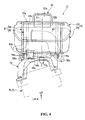
- FIG. 4 is a rear view of the air cleaner device
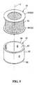
- FIG. 5 is a perspective view of an element and an element holder of the air cleaner device.
- FIG. 6 is a cross sectional view taken along the axis line of the element and the element holder.
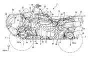
- a saddle-ride type four-wheeled vehicle (vehicle) 1 shown in FIG. 1 includes left and right front wheels 2 and rear wheels 3 , all of which are low-pressure balloon tires each having a relatively large diameter, in the front and rear of the downsized and lightweight vehicle body, and is configured as an ATV (All Terrain Vehicle) in which the running through performance on an irregular terrain is enhanced by securing a large ground clearance.
- ATV All Terrain Vehicle
- a body frame 4 of the saddle-ride type four-wheeled vehicle 1 forms a long box structure extending in the front-rear direction at a middle portion in the vehicle-width direction (left-right direction).
- An independent front suspension (not shown) is supported at a front portion of the body frame 4
- an independent rear suspension (not shown) is similarly supported at a rear portion thereof.
- An engine (internal combustion engine) 5 as a power plant of the vehicle is mounted at a substantially middle portion of the body frame 4 .
- the engine 5 is, for example, a water-cooled two-cylinder engine, and is vertically laid out so that a rotational axis line of a crankshaft is directed in the front-rear direction.
- a crankcase 5 a configuring a lower portion of the engine 5 also serves as a transmission case, and front and rear propeller shafts 6 and 8 are derived from the lower front side and the lower rear side of the crankcase 5 a toward the front and rear, respectively.
- the respective propeller shafts 6 and 8 allow for power transmission to the left and right front wheels 2 and rear wheels 3 through front and rear final assemblies 7 and 9 supported at the front lower side and the rear lower side of the body frame 4 , respectively, and through a drive shaft (not shown). Specifically, a rotational drive power from the engine 5 is output to the respective propeller shafts 6 and 8 through a transmission (not shown) in the crankcase 5 a, and then is transmitted to the left and right front wheels 2 and rear wheels 3 through the respective final assemblies 7 and 9 , and the like.
- a two-wheel-drive/four-wheel-drive switching mechanism 7 a by which a rotational drive power from the front propeller shaft 6 can be connected or disconnected is accommodated in a rear portion of a casing of the front final assembly 7 , and a differential mechanism 7 b which can absorb a difference in rotational speed between left and right drive shafts (the left and right front wheels 2 ), and a differential lock switching mechanism 7 c which can lock the differential are accommodated in a front portion of the casing.
- a differential mechanism 9 b which can absorb a difference in rotational speed between left and right drive shafts (the left and right rear wheels 3 ), and a differential lock switching mechanism 9 c which can lock the differential are accommodated in a casing of the rear final assembly 9 .
- a cylinder part 5 b is provided in an erect manner on the crankcase 5 a of the engine 5 , and an air cleaner device I 1 for engine intake is located above the cylinder part 5 b .
- Outside air filtered in the air cleaner device 11 is taken in the inside of the cylinder from the right side of the cylinder part 5 b through a throttle body (not shown).
- Exhaust air from the inside of the cylinder is taken to the outside of the cylinder through exhaust pipes 12 connected to the left side of the cylinder part 5 b .
- the exhaust pipes 12 are bent on the left side of the cylinder part 5 b to extend to the rear, and are connected to a silencer 12 a arranged on the rear left side of the vehicle body.
- a steering shaft 13 , the air cleaner device 11 , and a saddle-ride type seat 14 for a rider are positioned, in the order from the front side, at upper portions of the body frame 4 , and a fuel tank 15 is arranged below a rear portion of the seat 14 .
- a bar-type handlebar 16 is attached to an upper end of the steering shaft 13 , knuckles (not shown) of the left and right front wheels 2 are coupled to a lower end of the steering shaft 13 through left and right tie rods and the like, and a steering angle can be applied to the left and right front wheels 2 by rotational operation of the handlebar 16 .
- An electric motor-integrated actuator unit 17 is provided at a lower portion of the steering shaft 13 , so that an electric power steering device for applying a steering assist power to a steering system by using the electric motor as a drive source is configured.
- a radiator 18 for cooling the engine is arranged in front of a lower portion of the steering shaft 13 .
- the reference numerals 18 a and 18 b in the drawing illustrate a water pump provided on the front side of the crankcase 5 a and a thermostat provided on the front side of the cylinder part 5 b of the engine 5 , respectively.
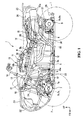
- the body frame 4 is formed by integrally coupling a plurality of kinds of steel materials by welding, and the like. Specifically, the body frame 4 forms a pair of left and right closed-loop structures by using left and right upper frames 31 and left and right lower frames 32 , and the like. By coupling the closed-loop structures to each other through a plurality of cross members, a long box structure extending in the front-rear direction is formed at a middle portion in the vehicle-width direction.
- Each upper frame 31 includes an upper inclined part 31 a which extends slightly downward to the rear on the outer side of an upper portion of the body frame 4 and a front drooping part 31 b which extends downward from a front end of each upper inclined part 31 a, and is integrally formed by bending a single steel pipe.
- each lower frame 32 is arranged in a substantially horizontal direction on the outer side of a lower portion of the body frame 4 , and is integrally formed by bending a single steel pipe.
- the lower frames 32 are moderately bent so that a distance between intermediate portions in the front-rear direction becomes maximum, and a distance between front portions and a distance between rear portions are reduced.
- a front end and a rear end of each lower frame 32 are bent upward to the front and upward to the rear, respectively.
- a front lower sub-frame 33 extends upward to the front from the front side of an intermediate portion of each lower frame 32 .
- Each front lower sub-frame 33 is formed in a bent manner so that a front inclined part 33 b thereof is moderately inclined as compared to a rear inclined part 33 a thereof.
- a front sub-frame 34 extends toward a front end of each lower frame 32 , while being appropriately bent from the front side of the upper inclined part 31 a of each upper frame 31 .
- Each front sub-frame 34 forms an upper inclined part 34 a extending substantially in parallel to the upper inclined part 31 a from the front side of the upper inclined part 31 a of each upper frame 31 , and then forms a front drooping part 34 b which is bent downward to extend diagonally downward to the front.
- Each front drooping part 34 forms a crank shape in such a manner that each lower side thereof is moderately changed to the front to reach a front end of the lower frame 32 .
- each front lower sub-frame 33 is connected to the crank-shaped portion of the front drooping part 34 b of each front sub-frame 34 at the rear side, and a lower end of the front drooping part 31 b of each upper frame 31 is connected to an intermediate portion, in the front-rear direction, of each front lower sub-frame 33 at the upper side.
- a region configured by connecting the front drooping part 31 b of each upper frame 31 to the rear inclined part 33 a of each front lower sub-frame 33 is referred to as a front-side down frame part 35 in some cases.
- a rear support frame (hereinafter, referred to as a rear-side down frame in some cases) 36 which is inclined upward to the rear is provided between a rear portion of each upper frame 31 and the rear side of an intermediate portion of each lower frame 32 .
- a rear sub-frame 37 extends to the rear from an upper portion of each rear support frame 36 , and a rear end of each rear sub-frame 37 is bent upward to be connected to a rear end of each upper frame 31 at the lower side.
- a rear gusset frame 38 which is inclined upward to the rear is provided between an upper portion of each rear support frame 36 and an intermediate portion of each upper frame 31 .
- the upper frames 31 , the front-side down frame parts 35 , the lower frames 32 , and the rear-side down frames 36 form a pair of left and right closed-loop structures, the inside of which configures a main frame part 39 for supporting the engine 5 .
- the reference numeral 41 a denotes an upper gusset provided between a bent portion between the upper inclined part 31 a and the front drooping part 31 b of each upper frame 31 , and the upper inclined part 34 a of each front sub-frame 34
- the reference numeral 41 b denotes a middle gusset provided between the front drooping part 31 b of each upper frame 31 and the front inclined part 33 b of each front lower sub-frame 33
- the reference numeral 41 c denotes a lower gusset provided between the rear inclined part 33 a of each front lower sub-frame 33 and a front portion of each lower frame 32
- the reference numeral 42 a denotes a bracket for supporting an upper portion of the steering shaft 13 provided between the upper inclined parts 34 a of the front sub-frames 34
- the reference numeral 42 b denotes a plate for supporting a lower portion of the steering shaft 13 provided between the front inclined parts 33 b of the front lower sub-frames 33
- the reference numeral 43 denotes a bracket for supporting an upper portion of a cushion, fixed to the front drooping part 34 b of each front sub-frame 34
- the reference numeral 43 a denotes a cross member for supporting a front portion of an upper arm, provided between the crank-shaped portions of the front drooping parts 34 b of the front sub-frames 34
- the reference numeral 43 b denotes a bracket for supporting a rear portion of the upper arm, fixed to the front inclined part 33 b of each front lower sub-frame 33
- the reference numeral 44 a denotes a cross member for supporting a front portion of a lower arm, provided between front ends of the lower frames 32
- the reference numeral 44 b denotes a cross member for supporting a rear portion of the lower arm, provided between front portions of the lower frames 32 .
- the reference numeral 47 denotes a bracket for supporting an upper portion of the cushion, provided between a rear portion of each upper frame 31 and an intermediate portion of each rear sub-frame 37
- the reference numeral 47 a denotes a bracket for supporting a front portion of the upper arm, provided between an intermediate portion of each rear sub-frame 37 and a rear portion of each lower frame 32
- the reference numeral 47 b denotes a bracket for supporting a rear portion of the upper arm, fixed to a rear portion of each rear sub-frame 37
- the reference numeral 48 a denotes a bracket for supporting a front portion of the lower arm, fixed to a rear portion of each lower frame 32
- the reference numeral 48 b denotes a bracket for supporting a rear portion of the lower arm, fixed to a rear end of each lower frame 32 .
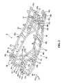
- the air cleaner device 11 has a basic configuration in which an air cleaner element (hereinafter, referred to simply as an element in some cases) 61 and an element holder 66 for holding the element are attachably and detachably accommodated in an air cleaner case 51 having an intake duct 52 , and is elastically supported by the cylinder part 5 b (the cylinder head or head cover) of the engine 5 through a support frame 53 made of, for example, a steel sheet, a plurality of rubber bushes and the like.
- an air cleaner element hereinafter, referred to simply as an element in some cases
- an element holder 66 for holding the element are attachably and detachably accommodated in an air cleaner case 51 having an intake duct 52 , and is elastically supported by the cylinder part 5 b (the cylinder head or head cover) of the engine 5 through a support frame 53 made of, for example, a steel sheet, a plurality of rubber bushes and the like.
- the intake duct 52 is integrally formed with a front upper wall 55 a , as a part of the intake duct 52 , of the air cleaner case 51 (the upper lid 55 ).
- an intake port 52 a which is an intake air upstream end is open to the rear on the upper side of an intermediate portion, in the front-rear direction, of the air cleaner case 51 .
- the intake duct 52 extends to the front from the intake port 52 a , and then forms an intake passage which is bent downward.
- a collar part 52 a which penetrates the front upper wall 55 a to protrude inside the air cleaner case 51 is formed on the intake air downstream side of the intake duct 52 .
- the element 61 is of a wet type which is used by soaking an element body 62 made of a cylindrical urethane foam in an oil and the like, can be reused after being washed with a wash oil, and has, for example, a two-layer structure in which surface roughness on the inner circumferential side is different from that on the outer circumferential side.
- the element 61 is accommodated in the air cleaner case 51 so that its axis line (center line) C is directed along the up-down direction. It should be noted that the element 61 and the element holder 66 in the embodiment are vertically symmetric.
- the element 61 is arranged between the front upper wall 55 a and a front lower wall 56 a of the air cleaner case 51 .
- the collar part 52 b of the intake duct 52 faces the inner circumferential side at an upper portion of the air cleaner element 61 .
- the inner circumferential side of the element 61 is defined as a dirty side (intake air upstream side) where outside air from the intake duct 52 directly flows, and the outer circumferential side of the element 61 is defined as a clean side (intake air downstream side).
- intake air upstream side intake air upstream side
- outer circumferential side of the element 61 is defined as a clean side (intake air downstream side).
- the intake nozzles 57 are provided so as to make a pair with each cylinder, and each pair is arranged in such a manner that one is located behind another.
- Each intake nozzle 57 extends upward from the right side of a rear lower wall of the air cleaner case 51 , and then is bent leftward, and an intake air upstream end thereof is allowed to be open leftward.
- the intake air downstream side of each intake nozzle 57 protrudes under the air cleaner case 51 , and is connected to an intake port of the engine 5 through a connecting tube (not shown), a throttle body (not shown), and the like.
- the reference numeral 57 a in the drawing denotes a breather hose through which the inside of the cylinder part 5 a of the engine 5 is in communication with the inside of air cleaner case 51 on the intake air downstream side
- the reference numeral 57 b denotes a drain port for discharging oil and water inside the air cleaner case 51
- the reference numeral 58 a denotes an intake air temperature sensor
- the reference numeral 58 b denotes a vacuum sensor
- the reference numeral 59 a denotes attaching parts where the air cleaner case 51 is attached or fixed to the support frame 53 through clips and the like
- the reference numeral 59 b denotes support parts for supporting a bumper rubber for vibration isolation of the air cleaner case 51 .
- support plates 63 in a disk shape with a hole which are made of an elastic member (such as rubber) are coaxially provided at respective upper and rear ends of element 61 .
- the inner diameter of each support plate 63 is equal to that of the element body 62
- the outer diameter of the each support plate 63 is larger than that of the element body 62 .
- the support plates 63 are integrally joined to upper and lower ends of the element body 62 (e.g. by welding.)
- the respective support plates 63 form element support parts 64 in a flange shape which expand (whose diameters increase) outside in the radius direction relative to the element body 62 at upper and lower ends of the element 61 .
- the element holder 66 is formed in a cylindrical shape which covers the outer circumference of the air cleaner element 61 , and is accommodated in the air cleaner case 51 so that its axis line is directed in the up-down direction.
- the element holder 66 is arranged coaxially with the element 61 , and upper and lower ends thereof are allowed to abut on the inner sides, in the axis direction, of the respective element support parts 64 so that the air cleaner element 61 is integrally supported.
- the element holder 66 is formed in such a manner that inner and outer cylinders 67 and 68 in a cylindrical shape formed by using, for example, punching plates made of thin steel sheets are arranged while having a predetermined space therebetween, and also functions as a flame trap (spark arrester) which prevents the air cleaner element 61 from being stained or damaged due to flame (backfire) and the like from the engine 5 .
- a flame trap spark arrester
- Circular plates 69 formed by using, for example, thin steel sheets are provided at respective upper and lower ends of the element holder 66 .
- Inner and outer flanges 69 a and 69 b protruding inside in the axis direction of the element holder are formed throughout the entire circumference at inner and outer circumferential edges of the respective circular plates 69 .
- Upper and lower ends of the inner and outer cylinders 67 and 68 are fitted between the inner and outer flanges 69 a and 69 b , and are joined to each other using adhesive and the like, so that the integral element holder 66 is configured.
- Short flanges 64 a erecting inside in the axis direction of the element 61 are formed throughout the entire circumference at outer circumferential edges of the respective element support parts 64 (the support plates 63 ) in the element 61 .
- spaces between the short flanges 64 a in the respective element support parts 64 and an edge of the element body 62 are referred to as upper and lower support concave parts 65 .
- the element holder 66 integrally supports the element 61 in a state where upper and lower ends (the respective circular plates 69 ) of the element holder 66 are fitted into the upper and lower support concave parts 65 .
- the followings are carried out.
- one of the support plates 63 of the element 61 together with the element body 62 , is inserted into the inside of the element holder 66 in a state where the support plate 63 is restorably squashed, the support plate 63 is allowed to reach the other end of the element holder 66 so as to restore the support plate 63 from the squashed state, and the upper and lower ends of the element holder 66 are inserted into the respective upper and lower support concave parts 65 , so that the element 61 is supported by the element holder 66 as shown in FIG. 6 .
- seal parts 64 b protruding outside in the radius direction are formed throughout the entire circumference at the outer circumferences of tip ends of the short flanges 64 a of the support plates 63 .
- the respective seal parts 64 b are brought into close contact with the inner circumferences of the upper and lower case-side concave parts 55 b and 56 b.
- the upper lid 55 is mounted on the case body 54 , and the upper support plate 63 is fitted into the upper case-side concave part 55 b of the front upper wall 55 a .
- the element holder 66 together with the respective element support parts 64 , is sandwiched between the front upper wall 55 a and the front lower wall 56 a of the air cleaner case 51 , and thus the element holder 66 and the element 61 are integrally held in the air cleaner case 51 .
- the seal parts 64 b at the outer circumferences of the respective support plates 63 are brought into close contact with the inner circumferences of the respective case-side concave parts 55 b and 56 b , and the upper and lower element holding parts are sandwiched between the front upper and lower walls 55 a and 56 a of the air cleaner case 51 and the upper and lower ends of the element holder 66 , respectively. Accordingly, spaces between the inner circumferential sides and the outer circumferential sides at the upper and lower ends of the element 61 (between the intake air upstream side and the intake air downstream side) are sealed.
- the air cleaner element holding structure in the embodiment is applied to the air cleaner device 11 in which the wet and cylindrical air cleaner element 61 and the element holder 66 for supporting the element are provided in the air cleaner case 51 having the intake duct 52 .
- the air cleaner element 61 has the element support parts 64 in a flange shape at both ends in the axis direction, and allows the intake duct 52 to face the inner circumferential side of the element, so that the inner circumferential side is defined as a dirty side, and the outer circumferential side is defined as a clean side.
- the element holder 66 has a cylindrical shape which covers the outer circumference of the air cleaner element 61 , and supports the air cleaner element 61 in such a manner that both ends, in the axis direction, of the holder are allowed to abut on the insides, in the axis direction, of the element support parts 64 ; and the air cleaner case 51 holds the element holder 66 and the air cleaner element 61 by sandwiching the element holder 66 , together with the element support parts 64 , with the case body 54 and the upper lid 55 .
- the element support parts 64 are formed by using elastic plates, and are formed integrally with the element body 62 . Accordingly, spaces between the air cleaner case 51 and the element body 62 can be sealed through the element support parts 64 .
Landscapes
- Engineering & Computer Science (AREA)
- Chemical & Material Sciences (AREA)
- Combustion & Propulsion (AREA)
- Mechanical Engineering (AREA)
- General Engineering & Computer Science (AREA)
- Automatic Cycles, And Cycles In General (AREA)
- Filtering Of Dispersed Particles In Gases (AREA)
Abstract
Description
- The present invention relates to an air cleaner element holding structure. In addition, the present invention relates to an element holding structure for an air cleaner device for use in filtering an intake air for an engine of a vehicle.
- In a conventional element holding structure for an air cleaner device in which a wet air cleaner element and an element holder for supporting the element are accommodated in an air cleaner case having an intake duct, the air cleaner element has a cylindrical shape, and the intake duct is allowed to face the outer circumferential side of the element in the air cleaner case, so that the outer circumferential side of the element is defined as a dirty side (intake air upstream side) and the inner circumferential side thereof is defined as a clean side (intake air downstream side), and the air cleaner element is held in the air cleaner case through the element holder arranged on the inner circumferential side of the element (e.g., JP-A No. S62-074790). The element holder also functions as a flame trap (spark arrester) by which flame (backfire) and the like from an engine are prevented from reaching the air cleaner element.
- In the case of an air cleaner device of, for example, a multi-cylinder engine, it is desirable in some cases that the inner circumferential side of the air cleaner element in a cylindrical shape is defined as a dirty side and the outer circumferential side thereof is defined as a clean side. However, there is a problem in the conventional structure because an additional flame trap needs to be provided on the outer circumferential side of the element, and thus the number of components and steps for maintenance are increased.
- Accordingly, one object of the present invention is to reduce the number of components and steps for maintenance in an element holding structure for an air cleaner device in which the inner circumferential side of a wet and cylindrical air cleaner element is defined as a dirty side and the outer circumferential side thereof is defined as a clean side.
- One aspect of the present invention provides an air cleaner element holding structure for an air cleaner device (for example, an
air cleaner device 11 in the embodiment) in which a wet and cylindrical air cleaner element (for example, anair cleaner element 61 in the embodiment) and an element holder (for example, anelement holder 66 in the embodiment) for supporting the element are accommodated in an air cleaner case (for example, anair cleaner case 51 in the embodiment) having an intake duct (for example, anintake duct 52 in the embodiment). The air cleaner element has element support parts (for example,element support parts 64 in the embodiment) in a flange shape at both ends in the axis direction, and allows the intake duct to face the inner circumferential side of the element, so that the inner circumferential side is defined as a dirty side, and the outer circumferential side is defined as a clean side. The element holder has a cylindrical shape which covers the outer circumference of the air cleaner element, and supports the air cleaner element in such a manner that both ends, in the axis direction, of the holder are allowed to abut on the insides, in the axis direction, of the element support parts. The air cleaner case holds the element holder and the air cleaner element by sandwiching the element holder, together with the element support parts, with a case body (for example, acase body 54 in the embodiment) and a lid (for example, anupper lid 55 in the embodiment). - Accordingly, the element holder covers the outer circumferential side of the air cleaner element, so that the element holder can be functioned as a flame trap, and the number of components can be suppressed without a need of a special flame trap. Also, by detaching the upper lid of the air cleaner case, the air cleaner element and the element holder are integrally detached, and thus the maintenance can be easily performed.
- Another aspect of the present invention provides an air cleaner element holding structure, wherein the element support parts are formed by using elastic members, and are provided integrally with an element body (for example, an
element body 62 in the embodiment). - Accordingly, spaces between the air cleaner case and the element body can be sealed through the element support parts.
- A preferred embodiment of the present invention will be described with reference to the accompanying drawings, wherein:
-
FIG. 1 is a side view of a saddle-ride type four-wheeled vehicle of the present invention; -
FIG. 2 is a perspective view of a body frame of the saddle-ride type four-wheeled vehicle; -
FIG. 3 is a side view of an air cleaner device of the saddle-ride type four-wheeled vehicle; -
FIG. 4 is a rear view of the air cleaner device; -
FIG. 5 is a perspective view of an element and an element holder of the air cleaner device; and -
FIG. 6 is a cross sectional view taken along the axis line of the element and the element holder. - Hereinafter, an embodiment of the present invention will be described with reference to the drawings. It should be noted that the directions of front, rear, left, right, and the like in the following description are the same as those of a vehicle unless otherwise described. Further, arrows FR, LH, and UP in the drawings indicate the front, left, and upper of the vehicle, respectively.
- A saddle-ride type four-wheeled vehicle (vehicle) 1 shown in
FIG. 1 includes left and rightfront wheels 2 andrear wheels 3, all of which are low-pressure balloon tires each having a relatively large diameter, in the front and rear of the downsized and lightweight vehicle body, and is configured as an ATV (All Terrain Vehicle) in which the running through performance on an irregular terrain is enhanced by securing a large ground clearance. - A
body frame 4 of the saddle-ride type four-wheeled vehicle 1 forms a long box structure extending in the front-rear direction at a middle portion in the vehicle-width direction (left-right direction). An independent front suspension (not shown) is supported at a front portion of thebody frame 4, and an independent rear suspension (not shown) is similarly supported at a rear portion thereof. - An engine (internal combustion engine) 5 as a power plant of the vehicle is mounted at a substantially middle portion of the
body frame 4. Theengine 5 is, for example, a water-cooled two-cylinder engine, and is vertically laid out so that a rotational axis line of a crankshaft is directed in the front-rear direction. Acrankcase 5 a configuring a lower portion of theengine 5 also serves as a transmission case, and front andrear propeller shafts crankcase 5 a toward the front and rear, respectively. - The
respective propeller shafts front wheels 2 andrear wheels 3 through front and rearfinal assemblies 7 and 9 supported at the front lower side and the rear lower side of thebody frame 4, respectively, and through a drive shaft (not shown). Specifically, a rotational drive power from theengine 5 is output to therespective propeller shafts crankcase 5 a, and then is transmitted to the left and rightfront wheels 2 andrear wheels 3 through the respectivefinal assemblies 7 and 9, and the like. - A two-wheel-drive/four-wheel-
drive switching mechanism 7 a by which a rotational drive power from thefront propeller shaft 6 can be connected or disconnected is accommodated in a rear portion of a casing of the front final assembly 7, and adifferential mechanism 7 b which can absorb a difference in rotational speed between left and right drive shafts (the left and right front wheels 2), and a differentiallock switching mechanism 7 c which can lock the differential are accommodated in a front portion of the casing. On the other hand, adifferential mechanism 9 b which can absorb a difference in rotational speed between left and right drive shafts (the left and right rear wheels 3), and a differentiallock switching mechanism 9 c which can lock the differential are accommodated in a casing of the rearfinal assembly 9. - A
cylinder part 5 b is provided in an erect manner on thecrankcase 5 a of theengine 5, and an air cleaner device I1 for engine intake is located above thecylinder part 5 b. Outside air filtered in theair cleaner device 11 is taken in the inside of the cylinder from the right side of thecylinder part 5 b through a throttle body (not shown). Exhaust air from the inside of the cylinder is taken to the outside of the cylinder throughexhaust pipes 12 connected to the left side of thecylinder part 5 b. Theexhaust pipes 12 are bent on the left side of thecylinder part 5 b to extend to the rear, and are connected to asilencer 12 a arranged on the rear left side of the vehicle body. - A
steering shaft 13, theair cleaner device 11, and a saddle-ride type seat 14 for a rider are positioned, in the order from the front side, at upper portions of thebody frame 4, and afuel tank 15 is arranged below a rear portion of theseat 14. A bar-type handlebar 16 is attached to an upper end of thesteering shaft 13, knuckles (not shown) of the left and rightfront wheels 2 are coupled to a lower end of thesteering shaft 13 through left and right tie rods and the like, and a steering angle can be applied to the left and rightfront wheels 2 by rotational operation of thehandlebar 16. - An electric motor-integrated
actuator unit 17 is provided at a lower portion of thesteering shaft 13, so that an electric power steering device for applying a steering assist power to a steering system by using the electric motor as a drive source is configured. Aradiator 18 for cooling the engine is arranged in front of a lower portion of thesteering shaft 13. It should be noted that thereference numerals crankcase 5 a and a thermostat provided on the front side of thecylinder part 5 b of theengine 5, respectively. - A front
vehicle body cover 19 made of resin which appropriately covers a front portion of the vehicle body,front fenders 21 similarly made of resin which cover the left and rightfront wheels 2 from the above to the rear, and afront protector 22 and afront carrier 23, both of which are mainly made of steel are attached to front portions of thebody frame 4. Further,rear fenders 24 made of resin which cover the left and rightrear wheels 3 from the above to the front, and arear carrier 25 and atrailer hitch 26, both of which are mainly made of steel are attached to rear portions of thebody frame 4. - With reference to
FIG. 2 , thebody frame 4 is formed by integrally coupling a plurality of kinds of steel materials by welding, and the like. Specifically, thebody frame 4 forms a pair of left and right closed-loop structures by using left and rightupper frames 31 and left and rightlower frames 32, and the like. By coupling the closed-loop structures to each other through a plurality of cross members, a long box structure extending in the front-rear direction is formed at a middle portion in the vehicle-width direction. - Each
upper frame 31 includes an upperinclined part 31 a which extends slightly downward to the rear on the outer side of an upper portion of thebody frame 4 and a front droopingpart 31 b which extends downward from a front end of each upperinclined part 31 a, and is integrally formed by bending a single steel pipe. - On the other hand, each
lower frame 32 is arranged in a substantially horizontal direction on the outer side of a lower portion of thebody frame 4, and is integrally formed by bending a single steel pipe. Thelower frames 32 are moderately bent so that a distance between intermediate portions in the front-rear direction becomes maximum, and a distance between front portions and a distance between rear portions are reduced. A front end and a rear end of eachlower frame 32 are bent upward to the front and upward to the rear, respectively. - A front
lower sub-frame 33 extends upward to the front from the front side of an intermediate portion of eachlower frame 32. Each frontlower sub-frame 33 is formed in a bent manner so that a front inclined part 33 b thereof is moderately inclined as compared to a rearinclined part 33 a thereof. - A
front sub-frame 34 extends toward a front end of eachlower frame 32, while being appropriately bent from the front side of the upperinclined part 31 a of eachupper frame 31. Eachfront sub-frame 34 forms an upperinclined part 34 a extending substantially in parallel to the upperinclined part 31 a from the front side of the upperinclined part 31 a of eachupper frame 31, and then forms a frontdrooping part 34 b which is bent downward to extend diagonally downward to the front. Each front droopingpart 34 forms a crank shape in such a manner that each lower side thereof is moderately changed to the front to reach a front end of thelower frame 32. - A front end of each front
lower sub-frame 33 is connected to the crank-shaped portion of thefront drooping part 34 b of eachfront sub-frame 34 at the rear side, and a lower end of thefront drooping part 31 b of eachupper frame 31 is connected to an intermediate portion, in the front-rear direction, of each frontlower sub-frame 33 at the upper side. It should be noted that a region configured by connecting the front droopingpart 31 b of eachupper frame 31 to the rear inclinedpart 33 a of each frontlower sub-frame 33 is referred to as a front-side downframe part 35 in some cases. - A rear support frame (hereinafter, referred to as a rear-side down frame in some cases) 36 which is inclined upward to the rear is provided between a rear portion of each
upper frame 31 and the rear side of an intermediate portion of eachlower frame 32. Arear sub-frame 37 extends to the rear from an upper portion of eachrear support frame 36, and a rear end of eachrear sub-frame 37 is bent upward to be connected to a rear end of eachupper frame 31 at the lower side. Arear gusset frame 38 which is inclined upward to the rear is provided between an upper portion of eachrear support frame 36 and an intermediate portion of eachupper frame 31. - The upper frames 31, the front-side down
frame parts 35, thelower frames 32, and the rear-side down frames 36 form a pair of left and right closed-loop structures, the inside of which configures amain frame part 39 for supporting theengine 5. - It should be noted that the
reference numeral 41 a denotes an upper gusset provided between a bent portion between the upperinclined part 31 a and the front droopingpart 31 b of eachupper frame 31, and the upperinclined part 34 a of eachfront sub-frame 34, thereference numeral 41 b denotes a middle gusset provided between the front droopingpart 31 b of eachupper frame 31 and the front inclined part 33 b of each frontlower sub-frame 33, the reference numeral 41 c denotes a lower gusset provided between the rearinclined part 33 a of each frontlower sub-frame 33 and a front portion of eachlower frame 32, thereference numeral 42 a denotes a bracket for supporting an upper portion of the steeringshaft 13 provided between the upperinclined parts 34 a of thefront sub-frames 34, and thereference numeral 42 b denotes a plate for supporting a lower portion of the steeringshaft 13 provided between the front inclined parts 33 b of the frontlower sub-frames 33. - Further, the
reference numeral 43 denotes a bracket for supporting an upper portion of a cushion, fixed to the front droopingpart 34 b of eachfront sub-frame 34, thereference numeral 43 a denotes a cross member for supporting a front portion of an upper arm, provided between the crank-shaped portions of the frontdrooping parts 34 b of thefront sub-frames 34, thereference numeral 43 b denotes a bracket for supporting a rear portion of the upper arm, fixed to the front inclined part 33 b of each frontlower sub-frame 33, thereference numeral 44 a denotes a cross member for supporting a front portion of a lower arm, provided between front ends of thelower frames 32, thereference numeral 44 b denotes a cross member for supporting a rear portion of the lower arm, provided between front portions of the lower frames 32. - Furthermore, the
reference numeral 45 a denotes a center upper-cross-member provided between intermediate portions of theupper frames 31, thereference numeral 45 b denotes a rear upper-cross-member provided between intermediate portions of therear sub-frames 37, thereference numeral 45 c denotes a rear end upper-cross-member provided between rear ends of theupper frames 31, thereference numeral 46 a denotes a center lower-cross-member provided between the front sides of intermediate portions of thelower frames 32, thereference numeral 46 b denotes a step-part cross member provided between the rear sides of intermediate portions of thelower frames 32, thereference numeral 46 c denotes a rear lower-cross-member provided between rear portions of thelower frames 32, and thereference numeral 46 d denotes a rear end lower-cross-member provided between rear ends of the lower frames 32. - Further, the
reference numeral 47 denotes a bracket for supporting an upper portion of the cushion, provided between a rear portion of eachupper frame 31 and an intermediate portion of eachrear sub-frame 37, thereference numeral 47 a denotes a bracket for supporting a front portion of the upper arm, provided between an intermediate portion of eachrear sub-frame 37 and a rear portion of eachlower frame 32, thereference numeral 47 b denotes a bracket for supporting a rear portion of the upper arm, fixed to a rear portion of eachrear sub-frame 37, thereference numeral 48 a denotes a bracket for supporting a front portion of the lower arm, fixed to a rear portion of eachlower frame 32, and thereference numeral 48 b denotes a bracket for supporting a rear portion of the lower arm, fixed to a rear end of eachlower frame 32. - As shown in
FIGS. 3 and 4 , theair cleaner device 11 has a basic configuration in which an air cleaner element (hereinafter, referred to simply as an element in some cases) 61 and anelement holder 66 for holding the element are attachably and detachably accommodated in an aircleaner case 51 having anintake duct 52, and is elastically supported by thecylinder part 5 b (the cylinder head or head cover) of theengine 5 through asupport frame 53 made of, for example, a steel sheet, a plurality of rubber bushes and the like. - The
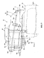
air cleaner case 51 is made of, for example, synthetic resin, and is formed in a relatively-long box shape extending in the front-rear direction. Theair cleaner case 51 is divided into acase body 54 which is open upward and anupper lid 55 which is open downward and is relatively shallow in the up-down direction. Anupper opening 54 a of thecase body 54 is formed along a dividing plane S which is inclined downward to the rear, and theupper opening 54 a can be closed with theupper lid 55. A plurality of plate clips 54 b in a C-shape made of spring steel and the like are provided at the circumference of the case opening in thecase body 54, and theupper lid 55 can be detachably attached to thecase body 55 through the plate clips. - The
intake duct 52 is integrally formed with a frontupper wall 55 a, as a part of theintake duct 52, of the air cleaner case 51 (the upper lid 55). In theintake duct 52, anintake port 52 a which is an intake air upstream end is open to the rear on the upper side of an intermediate portion, in the front-rear direction, of theair cleaner case 51. Theintake duct 52 extends to the front from theintake port 52 a, and then forms an intake passage which is bent downward. Acollar part 52 a which penetrates the frontupper wall 55 a to protrude inside theair cleaner case 51 is formed on the intake air downstream side of theintake duct 52. - With reference to
FIGS. 5 and 6 together, theelement 61 is of a wet type which is used by soaking anelement body 62 made of a cylindrical urethane foam in an oil and the like, can be reused after being washed with a wash oil, and has, for example, a two-layer structure in which surface roughness on the inner circumferential side is different from that on the outer circumferential side. Theelement 61 is accommodated in theair cleaner case 51 so that its axis line (center line) C is directed along the up-down direction. It should be noted that theelement 61 and theelement holder 66 in the embodiment are vertically symmetric. Theelement 61 is arranged between the frontupper wall 55 a and a frontlower wall 56 a of theair cleaner case 51. Thecollar part 52 b of theintake duct 52 faces the inner circumferential side at an upper portion of theair cleaner element 61. - Specifically, as shown in
FIGS. 3 and 4 , the inner circumferential side of theelement 61 is defined as a dirty side (intake air upstream side) where outside air from theintake duct 52 directly flows, and the outer circumferential side of theelement 61 is defined as a clean side (intake air downstream side). When theengines 5 is operated, outside air is introduced to the inner circumferential side of the element from theintake duct 52 by a manifold air pressure, the outside air is filtered to reach the outer circumferential side of the element, and then is supplied to theengine 5 throughintake nozzles 57 arranged inside a rear portion of theair cleaner case 51. - The intake nozzles 57 are provided so as to make a pair with each cylinder, and each pair is arranged in such a manner that one is located behind another. Each
intake nozzle 57 extends upward from the right side of a rear lower wall of theair cleaner case 51, and then is bent leftward, and an intake air upstream end thereof is allowed to be open leftward. The intake air downstream side of eachintake nozzle 57 protrudes under theair cleaner case 51, and is connected to an intake port of theengine 5 through a connecting tube (not shown), a throttle body (not shown), and the like. - It should be noted that the
reference numeral 57 a in the drawing denotes a breather hose through which the inside of thecylinder part 5 a of theengine 5 is in communication with the inside of aircleaner case 51 on the intake air downstream side, thereference numeral 57 b denotes a drain port for discharging oil and water inside theair cleaner case 51, thereference numeral 58 a denotes an intake air temperature sensor, thereference numeral 58 b denotes a vacuum sensor, thereference numeral 59 a denotes attaching parts where theair cleaner case 51 is attached or fixed to thesupport frame 53 through clips and the like, and thereference numeral 59 b denotes support parts for supporting a bumper rubber for vibration isolation of theair cleaner case 51. - As shown in
FIGS. 5 and 6 ,support plates 63 in a disk shape with a hole which are made of an elastic member (such as rubber) are coaxially provided at respective upper and rear ends ofelement 61. The inner diameter of eachsupport plate 63 is equal to that of theelement body 62, whereas the outer diameter of the eachsupport plate 63 is larger than that of theelement body 62. Thesupport plates 63 are integrally joined to upper and lower ends of the element body 62 (e.g. by welding.) Therespective support plates 63 formelement support parts 64 in a flange shape which expand (whose diameters increase) outside in the radius direction relative to theelement body 62 at upper and lower ends of theelement 61. - The
element holder 66 is formed in a cylindrical shape which covers the outer circumference of theair cleaner element 61, and is accommodated in theair cleaner case 51 so that its axis line is directed in the up-down direction. Theelement holder 66 is arranged coaxially with theelement 61, and upper and lower ends thereof are allowed to abut on the inner sides, in the axis direction, of the respectiveelement support parts 64 so that theair cleaner element 61 is integrally supported. - The
element holder 66 is formed in such a manner that inner andouter cylinders air cleaner element 61 from being stained or damaged due to flame (backfire) and the like from theengine 5. -
Circular plates 69 formed by using, for example, thin steel sheets are provided at respective upper and lower ends of theelement holder 66. Inner andouter flanges circular plates 69. Upper and lower ends of the inner andouter cylinders outer flanges integral element holder 66 is configured. -
Short flanges 64 a erecting inside in the axis direction of theelement 61 are formed throughout the entire circumference at outer circumferential edges of the respective element support parts 64 (the support plates 63) in theelement 61. Hereinafter, spaces between theshort flanges 64 a in the respectiveelement support parts 64 and an edge of theelement body 62 are referred to as upper and lower supportconcave parts 65. Theelement holder 66 integrally supports theelement 61 in a state where upper and lower ends (the respective circular plates 69) of theelement holder 66 are fitted into the upper and lower supportconcave parts 65. - In the case where the
element 61 and theelement holder 66 are integrally assembled, the followings are carried out. First, from the separated state shown inFIG. 5 , one of thesupport plates 63 of theelement 61, together with theelement body 62, is inserted into the inside of theelement holder 66 in a state where thesupport plate 63 is restorably squashed, thesupport plate 63 is allowed to reach the other end of theelement holder 66 so as to restore thesupport plate 63 from the squashed state, and the upper and lower ends of theelement holder 66 are inserted into the respective upper and lower supportconcave parts 65, so that theelement 61 is supported by theelement holder 66 as shown inFIG. 6 . - In addition, as shown in
FIGS. 3 and 4 , upper and lower case-sideconcave parts lower support plates 63 of theelement 61 can be fitted are formed inside the case at the front upper andlower walls air cleaner case 51. Thesupport plates 63 are fitted into and supported by the respective case-sideconcave parts element 61 and theelement holder 66 are accommodated in theair cleaner case 51, and theupper lid 55 is integrally attached to thecase body 54. - With reference to
FIG. 6 , sealparts 64 b protruding outside in the radius direction are formed throughout the entire circumference at the outer circumferences of tip ends of theshort flanges 64 a of thesupport plates 63. When the upper andlower support plates 63 are fitted into the upper and lower case-sideconcave parts respective seal parts 64 b are brought into close contact with the inner circumferences of the upper and lower case-sideconcave parts - In a state where the
element 61 is supported at the inner circumference of theelement holder 66 and thelower support plate 63 is fitted into the lower case-sideconcave part 56 b of the frontlower wall 56 a of thecase body 54, theupper lid 55 is mounted on thecase body 54, and theupper support plate 63 is fitted into the upper case-sideconcave part 55 b of the frontupper wall 55 a. Accordingly, theelement holder 66, together with the respectiveelement support parts 64, is sandwiched between the frontupper wall 55 a and the frontlower wall 56 a of theair cleaner case 51, and thus theelement holder 66 and theelement 61 are integrally held in theair cleaner case 51. - At this time, the
seal parts 64 b at the outer circumferences of therespective support plates 63 are brought into close contact with the inner circumferences of the respective case-sideconcave parts lower walls air cleaner case 51 and the upper and lower ends of theelement holder 66, respectively. Accordingly, spaces between the inner circumferential sides and the outer circumferential sides at the upper and lower ends of the element 61 (between the intake air upstream side and the intake air downstream side) are sealed. - As described above, the air cleaner element holding structure in the embodiment is applied to the
air cleaner device 11 in which the wet and cylindrical aircleaner element 61 and theelement holder 66 for supporting the element are provided in theair cleaner case 51 having theintake duct 52. Theair cleaner element 61 has theelement support parts 64 in a flange shape at both ends in the axis direction, and allows theintake duct 52 to face the inner circumferential side of the element, so that the inner circumferential side is defined as a dirty side, and the outer circumferential side is defined as a clean side. In the meantime, theelement holder 66 has a cylindrical shape which covers the outer circumference of theair cleaner element 61, and supports theair cleaner element 61 in such a manner that both ends, in the axis direction, of the holder are allowed to abut on the insides, in the axis direction, of theelement support parts 64; and theair cleaner case 51 holds theelement holder 66 and theair cleaner element 61 by sandwiching theelement holder 66, together with theelement support parts 64, with thecase body 54 and theupper lid 55. - According to the configuration, the
element holder 66 covers the outer circumferential side of theair cleaner element 61, so that theelement holder 66 can be functioned as the flame trap, and the number of components can be suppressed without a need of a special flame trap. Further, by detaching theupper lid 55 of theair cleaner case 51, theair cleaner element 61 and theelement holder 66 are integrally detached, and thus the maintenance can be easily performed. - Further, in the air cleaner element holding structure, the
element support parts 64 are formed by using elastic plates, and are formed integrally with theelement body 62. Accordingly, spaces between theair cleaner case 51 and theelement body 62 can be sealed through theelement support parts 64.
Claims (6)
Applications Claiming Priority (2)
| Application Number | Priority Date | Filing Date | Title |
|---|---|---|---|
| JP2006296919A JP4588687B2 (en) | 2006-10-31 | 2006-10-31 | Air cleaner element holding structure |
| JP2006-296919 | 2006-10-31 |
Publications (2)
| Publication Number | Publication Date |
|---|---|
| US20080098701A1 true US20080098701A1 (en) | 2008-05-01 |
| US8545586B2 US8545586B2 (en) | 2013-10-01 |
Family
ID=39328493
Family Applications (1)
| Application Number | Title | Priority Date | Filing Date |
|---|---|---|---|
| US11/877,286 Active 2029-06-09 US8545586B2 (en) | 2006-10-31 | 2007-10-23 | Air cleaner element holding structure |
Country Status (2)
| Country | Link |
|---|---|
| US (1) | US8545586B2 (en) |
| JP (1) | JP4588687B2 (en) |
Cited By (8)
| Publication number | Priority date | Publication date | Assignee | Title |
|---|---|---|---|---|
| US20070012274A1 (en) * | 2005-06-23 | 2007-01-18 | Honda Motor Co., Ltd. | Air cleaner in all terrain vehicle |
| US20070045015A1 (en) * | 2005-08-31 | 2007-03-01 | Honda Giken Kogyo Kabushiki Kaisha | Battery arrangement structure of a vehicle |
| US20070095324A1 (en) * | 2005-10-28 | 2007-05-03 | Honda Motor Co., Ltd. | Vehicular air cleaner structure |
| US20080282654A1 (en) * | 2007-05-09 | 2008-11-20 | Ktm Sportmotorcycle Ag | Air intake apparatus |
| US20150275833A1 (en) * | 2012-12-17 | 2015-10-01 | Kawasaki Jukogyo Kabushiki Kaisha | Saddled vehicle |
| US20150274012A1 (en) * | 2014-03-31 | 2015-10-01 | Honda Motor Co., Ltd. | Arrangement of a vehicle assembly member |
| US9365241B1 (en) * | 2015-03-04 | 2016-06-14 | Honda Motor Co., Ltd. | Vehicle crash management apparatus and methods of use and manufacture thereof |
| US9714628B2 (en) | 2014-06-27 | 2017-07-25 | Yamaha Hatsudoki Kabushiki Kaisha | Air cleaner |
Families Citing this family (1)
| Publication number | Priority date | Publication date | Assignee | Title |
|---|---|---|---|---|
| JP5189936B2 (en) * | 2008-09-05 | 2013-04-24 | ヤマハ発動機株式会社 | Intake device for motorcycle |
Citations (26)
| Publication number | Priority date | Publication date | Assignee | Title |
|---|---|---|---|---|
| US3577632A (en) * | 1969-09-18 | 1971-05-04 | Siemens Ag | Method of producing semiconductor device in glass housing |
| US3612024A (en) * | 1969-11-03 | 1971-10-12 | John C Bandimere | Air cleaner bypass arrangement |
| US4071004A (en) * | 1976-01-08 | 1978-01-31 | Ostergaard Neil A | Electro-static fuel mixture system |
| US4074985A (en) * | 1976-05-04 | 1978-02-21 | Raymond Zeno Willas | Air filter |
| US4268289A (en) * | 1979-04-11 | 1981-05-19 | Barbron Corporation | Flame arresting air filter element |
| US4663041A (en) * | 1983-09-09 | 1987-05-05 | Kurashiki Baseki Kabushiki Kaisha | Fluorocarbon filter element |
| US5377632A (en) * | 1993-01-21 | 1995-01-03 | Aktiebolaget Electrolux | Cutting or sawing machine |
| US5505753A (en) * | 1994-09-12 | 1996-04-09 | Heysek; Ralph G. | Aircraft pneumatic air filter |
| US5871001A (en) * | 1996-02-05 | 1999-02-16 | Pfm Products, Inc. | Method and apparatus for air-intake cooling in an internal combustion engine |
| US6162269A (en) * | 1999-01-29 | 2000-12-19 | United Air Filter, Inc. | Filter assembly for cleaning cooling air for engines |
| US6261333B1 (en) * | 1999-07-09 | 2001-07-17 | Diesel Research, Inc. | Air filter for an internal combustion engine having a primary air region and a secondary air region |
| US6287354B1 (en) * | 1998-12-18 | 2001-09-11 | Honda Giken Kogyo Kabushiki Kaisha | Vehicular air cleaner device |
| US6387142B1 (en) * | 2000-06-19 | 2002-05-14 | Chicopee Engineering Associates, Inc. | Air/oil separator cap attachment system |
| US20040025810A1 (en) * | 2002-08-12 | 2004-02-12 | Davis Steven T. | Air cleaner assembly for internal combustion engines |
| US20040050766A1 (en) * | 2002-09-13 | 2004-03-18 | Zemin Jiang | Filter cartridge with floating seal |
| US20040163372A1 (en) * | 2003-02-25 | 2004-08-26 | Nguyen Ledu Q. | Environmentally friendly air filter for an internal combustion engine |
| US20040200354A1 (en) * | 2000-09-05 | 2004-10-14 | Donaldson Company, Inc. | Filtration arrangement utilizing pleated construction and method |
| US6863758B1 (en) * | 1997-08-25 | 2005-03-08 | Hydac Filtertechnik Gmbh | Method of assembling plastic filter element with plastic casing |
| US20050193695A1 (en) * | 2004-03-02 | 2005-09-08 | Holmes Lester E. | Air filter assembly system and method |
| US20050274666A1 (en) * | 2000-06-01 | 2005-12-15 | Maxwell Martin C | Extension and locking assembly for dripless element, and container therefore |
| US20060196359A1 (en) * | 2000-09-05 | 2006-09-07 | Donaldson Company, Inc. | Air filtration arrangements having fluted media constructions and methods |
| US7384440B2 (en) * | 2004-04-28 | 2008-06-10 | Kawasaki Jukogyo Kabushiki Kaisha | Air cleaner for engine of vehicle |
| US7572310B2 (en) * | 2000-12-04 | 2009-08-11 | Donaldson Company, Inc. | Filter system; element configuration; and methods |
| US7604677B2 (en) * | 2005-03-31 | 2009-10-20 | Honda Motor Co., Ltd. | Structure of air cleaner box |
| US7806953B2 (en) * | 2006-10-07 | 2010-10-05 | Andreas Stihl Ag & Co. Kg | Manually guided implement |
| US7867311B1 (en) * | 2006-11-16 | 2011-01-11 | Cummins Filtration Ip, Inc. | Filter assembly with trapped auxiliary flow component |
Family Cites Families (2)
| Publication number | Priority date | Publication date | Assignee | Title |
|---|---|---|---|---|
| JPS58104349U (en) * | 1982-01-07 | 1983-07-15 | 本田技研工業株式会社 | Air cleaner device |
| JPH0796396B2 (en) | 1985-09-27 | 1995-10-18 | スズキ株式会社 | Cooling system for vehicle air-cooled engine |
-
2006
- 2006-10-31 JP JP2006296919A patent/JP4588687B2/en not_active Expired - Fee Related
-
2007
- 2007-10-23 US US11/877,286 patent/US8545586B2/en active Active
Patent Citations (27)
| Publication number | Priority date | Publication date | Assignee | Title |
|---|---|---|---|---|
| US3577632A (en) * | 1969-09-18 | 1971-05-04 | Siemens Ag | Method of producing semiconductor device in glass housing |
| US3612024A (en) * | 1969-11-03 | 1971-10-12 | John C Bandimere | Air cleaner bypass arrangement |
| US4071004A (en) * | 1976-01-08 | 1978-01-31 | Ostergaard Neil A | Electro-static fuel mixture system |
| US4074985A (en) * | 1976-05-04 | 1978-02-21 | Raymond Zeno Willas | Air filter |
| US4268289A (en) * | 1979-04-11 | 1981-05-19 | Barbron Corporation | Flame arresting air filter element |
| US4663041A (en) * | 1983-09-09 | 1987-05-05 | Kurashiki Baseki Kabushiki Kaisha | Fluorocarbon filter element |
| US5377632A (en) * | 1993-01-21 | 1995-01-03 | Aktiebolaget Electrolux | Cutting or sawing machine |
| US5505753A (en) * | 1994-09-12 | 1996-04-09 | Heysek; Ralph G. | Aircraft pneumatic air filter |
| US5871001A (en) * | 1996-02-05 | 1999-02-16 | Pfm Products, Inc. | Method and apparatus for air-intake cooling in an internal combustion engine |
| US6863758B1 (en) * | 1997-08-25 | 2005-03-08 | Hydac Filtertechnik Gmbh | Method of assembling plastic filter element with plastic casing |
| US6287354B1 (en) * | 1998-12-18 | 2001-09-11 | Honda Giken Kogyo Kabushiki Kaisha | Vehicular air cleaner device |
| US6162269A (en) * | 1999-01-29 | 2000-12-19 | United Air Filter, Inc. | Filter assembly for cleaning cooling air for engines |
| US6261333B1 (en) * | 1999-07-09 | 2001-07-17 | Diesel Research, Inc. | Air filter for an internal combustion engine having a primary air region and a secondary air region |
| US20050274666A1 (en) * | 2000-06-01 | 2005-12-15 | Maxwell Martin C | Extension and locking assembly for dripless element, and container therefore |
| US6387142B1 (en) * | 2000-06-19 | 2002-05-14 | Chicopee Engineering Associates, Inc. | Air/oil separator cap attachment system |
| US20040200354A1 (en) * | 2000-09-05 | 2004-10-14 | Donaldson Company, Inc. | Filtration arrangement utilizing pleated construction and method |
| US6994742B2 (en) * | 2000-09-05 | 2006-02-07 | Donaldson Company, Inc. | Filtration arrangement utilizing pleated construction and method |
| US20060196359A1 (en) * | 2000-09-05 | 2006-09-07 | Donaldson Company, Inc. | Air filtration arrangements having fluted media constructions and methods |
| US7572310B2 (en) * | 2000-12-04 | 2009-08-11 | Donaldson Company, Inc. | Filter system; element configuration; and methods |
| US20040025810A1 (en) * | 2002-08-12 | 2004-02-12 | Davis Steven T. | Air cleaner assembly for internal combustion engines |
| US20040050766A1 (en) * | 2002-09-13 | 2004-03-18 | Zemin Jiang | Filter cartridge with floating seal |
| US20040163372A1 (en) * | 2003-02-25 | 2004-08-26 | Nguyen Ledu Q. | Environmentally friendly air filter for an internal combustion engine |
| US20050193695A1 (en) * | 2004-03-02 | 2005-09-08 | Holmes Lester E. | Air filter assembly system and method |
| US7384440B2 (en) * | 2004-04-28 | 2008-06-10 | Kawasaki Jukogyo Kabushiki Kaisha | Air cleaner for engine of vehicle |
| US7604677B2 (en) * | 2005-03-31 | 2009-10-20 | Honda Motor Co., Ltd. | Structure of air cleaner box |
| US7806953B2 (en) * | 2006-10-07 | 2010-10-05 | Andreas Stihl Ag & Co. Kg | Manually guided implement |
| US7867311B1 (en) * | 2006-11-16 | 2011-01-11 | Cummins Filtration Ip, Inc. | Filter assembly with trapped auxiliary flow component |
Cited By (13)
| Publication number | Priority date | Publication date | Assignee | Title |
|---|---|---|---|---|
| US20070012274A1 (en) * | 2005-06-23 | 2007-01-18 | Honda Motor Co., Ltd. | Air cleaner in all terrain vehicle |
| US7686873B2 (en) * | 2005-06-23 | 2010-03-30 | Honda Motor Co., Ltd. | Air cleaner in all terrain vehicle |
| US7828098B2 (en) * | 2005-08-31 | 2010-11-09 | Honda Giken Kogyo Kabushiki Kaisha | Battery arrangement structure of a vehicle |
| US20070045015A1 (en) * | 2005-08-31 | 2007-03-01 | Honda Giken Kogyo Kabushiki Kaisha | Battery arrangement structure of a vehicle |
| US20070095324A1 (en) * | 2005-10-28 | 2007-05-03 | Honda Motor Co., Ltd. | Vehicular air cleaner structure |
| US8152880B2 (en) * | 2007-05-09 | 2012-04-10 | Ktm Sportmotorcycle Ag | Air intake apparatus |
| US20080282654A1 (en) * | 2007-05-09 | 2008-11-20 | Ktm Sportmotorcycle Ag | Air intake apparatus |
| US20150275833A1 (en) * | 2012-12-17 | 2015-10-01 | Kawasaki Jukogyo Kabushiki Kaisha | Saddled vehicle |
| US9677518B2 (en) * | 2012-12-17 | 2017-06-13 | Kawasaki Jukogyo Kabushiki Kaisha | Saddled vehicle |
| US20150274012A1 (en) * | 2014-03-31 | 2015-10-01 | Honda Motor Co., Ltd. | Arrangement of a vehicle assembly member |
| US9346352B2 (en) * | 2014-03-31 | 2016-05-24 | Honda Motor Co., Ltd. | Arrangement of a vehicle assembly member |
| US9714628B2 (en) | 2014-06-27 | 2017-07-25 | Yamaha Hatsudoki Kabushiki Kaisha | Air cleaner |
| US9365241B1 (en) * | 2015-03-04 | 2016-06-14 | Honda Motor Co., Ltd. | Vehicle crash management apparatus and methods of use and manufacture thereof |
Also Published As
| Publication number | Publication date |
|---|---|
| US8545586B2 (en) | 2013-10-01 |
| JP2008115697A (en) | 2008-05-22 |
| JP4588687B2 (en) | 2010-12-01 |
Similar Documents
| Publication | Publication Date | Title |
|---|---|---|
| US8545586B2 (en) | Air cleaner element holding structure | |
| US7730986B2 (en) | Electric component arrangement structure for vehicle, vehicle having the same, and method for arranging electric component in vehicle | |
| JP4522902B2 (en) | Air cleaner box structure | |
| JP5856922B2 (en) | Air cleaner device for internal combustion engine | |
| US7407179B2 (en) | Saddle-ride type vehicle | |
| JP2000179415A (en) | Vehicle air cleaner | |
| CN105579337A (en) | Saddled vehicle | |
| EP2332813B1 (en) | Scooter type vehicle | |
| CN102285404B (en) | Fuel supply apparatus for vehicles | |
| AU2017213465B2 (en) | Oil filter attaching structure for vehicle-mounted internal combustion engine | |
| US20090057055A1 (en) | Muffler structure | |
| US9482197B2 (en) | Fuel supply structure in vehicle engine | |
| JP5854855B2 (en) | Air cleaner device for saddle riding type vehicle | |
| JP6879836B2 (en) | Saddle-type vehicle | |
| JP4128639B2 (en) | Motorcycle | |
| KR100652520B1 (en) | Air cleaner supporting structure in a v-type engine | |
| JP2014129057A (en) | Fuel tank structure | |
| JP7105686B2 (en) | work vehicle | |
| EP1683959B1 (en) | Air cleaner structure for vehicle | |
| JP5643031B2 (en) | Vehicle fuel supply device | |
| JP2889592B2 (en) | Motorcycle air intake system | |
| JP4528717B2 (en) | Air cleaner structure | |
| JP4283072B2 (en) | Piping structure of motorcycle | |
| JP6366193B2 (en) | Saddle riding | |
| WO2019064323A1 (en) | Air cleaner device for two-wheeled motor vehicles |
Legal Events
| Date | Code | Title | Description |
|---|---|---|---|
| AS | Assignment |
Owner name: HONDA MOTOR CO., LTD., JAPAN Free format text: ASSIGNMENT OF ASSIGNORS INTEREST;ASSIGNORS:TAKESHIMA, MASAO;KAITA, KIHOKO;REEL/FRAME:020070/0368 Effective date: 20070927 |
|
| STCF | Information on status: patent grant |
Free format text: PATENTED CASE |
|
| FEPP | Fee payment procedure |
Free format text: PAYOR NUMBER ASSIGNED (ORIGINAL EVENT CODE: ASPN); ENTITY STATUS OF PATENT OWNER: LARGE ENTITY |
|
| FPAY | Fee payment |
Year of fee payment: 4 |
|
| MAFP | Maintenance fee payment |
Free format text: PAYMENT OF MAINTENANCE FEE, 8TH YEAR, LARGE ENTITY (ORIGINAL EVENT CODE: M1552); ENTITY STATUS OF PATENT OWNER: LARGE ENTITY Year of fee payment: 8 |