US20080098780A1 - Systems and methods for treating solid waste - Google Patents
Systems and methods for treating solid waste Download PDFInfo
- Publication number
- US20080098780A1 US20080098780A1 US11/876,672 US87667207A US2008098780A1 US 20080098780 A1 US20080098780 A1 US 20080098780A1 US 87667207 A US87667207 A US 87667207A US 2008098780 A1 US2008098780 A1 US 2008098780A1
- Authority
- US
- United States
- Prior art keywords
- composting
- vessel portion
- openings
- waste
- interior
- Prior art date
- Legal status (The legal status is an assumption and is not a legal conclusion. Google has not performed a legal analysis and makes no representation as to the accuracy of the status listed.)
- Abandoned
Links
Images


Classifications
-
- C—CHEMISTRY; METALLURGY
- C02—TREATMENT OF WATER, WASTE WATER, SEWAGE, OR SLUDGE
- C02F—TREATMENT OF WATER, WASTE WATER, SEWAGE, OR SLUDGE
- C02F11/00—Treatment of sludge; Devices therefor
- C02F11/12—Treatment of sludge; Devices therefor by de-watering, drying or thickening
- C02F11/121—Treatment of sludge; Devices therefor by de-watering, drying or thickening by mechanical de-watering
-
- B—PERFORMING OPERATIONS; TRANSPORTING
- B01—PHYSICAL OR CHEMICAL PROCESSES OR APPARATUS IN GENERAL
- B01F—MIXING, e.g. DISSOLVING, EMULSIFYING OR DISPERSING
- B01F27/00—Mixers with rotary stirring devices in fixed receptacles; Kneaders
- B01F27/80—Mixers with rotary stirring devices in fixed receptacles; Kneaders with stirrers rotating about a substantially vertical axis
- B01F27/92—Mixers with rotary stirring devices in fixed receptacles; Kneaders with stirrers rotating about a substantially vertical axis with helices or screws
- B01F27/921—Mixers with rotary stirring devices in fixed receptacles; Kneaders with stirrers rotating about a substantially vertical axis with helices or screws with helices centrally mounted in the receptacle
-
- B—PERFORMING OPERATIONS; TRANSPORTING
- B01—PHYSICAL OR CHEMICAL PROCESSES OR APPARATUS IN GENERAL
- B01F—MIXING, e.g. DISSOLVING, EMULSIFYING OR DISPERSING
- B01F27/00—Mixers with rotary stirring devices in fixed receptacles; Kneaders
- B01F27/80—Mixers with rotary stirring devices in fixed receptacles; Kneaders with stirrers rotating about a substantially vertical axis
- B01F27/92—Mixers with rotary stirring devices in fixed receptacles; Kneaders with stirrers rotating about a substantially vertical axis with helices or screws
- B01F27/922—Mixers with rotary stirring devices in fixed receptacles; Kneaders with stirrers rotating about a substantially vertical axis with helices or screws with two or more helices, e.g. with intermeshing helices
-
- C—CHEMISTRY; METALLURGY
- C05—FERTILISERS; MANUFACTURE THEREOF
- C05F—ORGANIC FERTILISERS NOT COVERED BY SUBCLASSES C05B, C05C, e.g. FERTILISERS FROM WASTE OR REFUSE
- C05F17/00—Preparation of fertilisers characterised by biological or biochemical treatment steps, e.g. composting or fermentation
- C05F17/90—Apparatus therefor
- C05F17/914—Portable or transportable devices, e.g. transport containers or trucks
-
- C—CHEMISTRY; METALLURGY
- C05—FERTILISERS; MANUFACTURE THEREOF
- C05F—ORGANIC FERTILISERS NOT COVERED BY SUBCLASSES C05B, C05C, e.g. FERTILISERS FROM WASTE OR REFUSE
- C05F17/00—Preparation of fertilisers characterised by biological or biochemical treatment steps, e.g. composting or fermentation
- C05F17/90—Apparatus therefor
- C05F17/964—Constructional parts, e.g. floors, covers or doors
-
- F—MECHANICAL ENGINEERING; LIGHTING; HEATING; WEAPONS; BLASTING
- F26—DRYING
- F26B—DRYING SOLID MATERIALS OR OBJECTS BY REMOVING LIQUID THEREFROM
- F26B11/00—Machines or apparatus for drying solid materials or objects with movement which is non-progressive
- F26B11/12—Machines or apparatus for drying solid materials or objects with movement which is non-progressive in stationary drums or other mainly-closed receptacles with moving stirring devices
- F26B11/14—Machines or apparatus for drying solid materials or objects with movement which is non-progressive in stationary drums or other mainly-closed receptacles with moving stirring devices the stirring device moving in a horizontal or slightly-inclined plane
-
- F—MECHANICAL ENGINEERING; LIGHTING; HEATING; WEAPONS; BLASTING
- F26—DRYING
- F26B—DRYING SOLID MATERIALS OR OBJECTS BY REMOVING LIQUID THEREFROM
- F26B17/00—Machines or apparatus for drying materials in loose, plastic, or fluidised form, e.g. granules, staple fibres, with progressive movement
- F26B17/18—Machines or apparatus for drying materials in loose, plastic, or fluidised form, e.g. granules, staple fibres, with progressive movement with movement performed by rotating helical blades or other rotary conveyors which may be heated moving materials in stationary chambers, e.g. troughs
- F26B17/20—Machines or apparatus for drying materials in loose, plastic, or fluidised form, e.g. granules, staple fibres, with progressive movement with movement performed by rotating helical blades or other rotary conveyors which may be heated moving materials in stationary chambers, e.g. troughs the axis of rotation being horizontal or slightly inclined
-
- C—CHEMISTRY; METALLURGY
- C02—TREATMENT OF WATER, WASTE WATER, SEWAGE, OR SLUDGE
- C02F—TREATMENT OF WATER, WASTE WATER, SEWAGE, OR SLUDGE
- C02F11/00—Treatment of sludge; Devices therefor
- C02F11/12—Treatment of sludge; Devices therefor by de-watering, drying or thickening
- C02F11/16—Treatment of sludge; Devices therefor by de-watering, drying or thickening using drying or composting beds
-
- C—CHEMISTRY; METALLURGY
- C02—TREATMENT OF WATER, WASTE WATER, SEWAGE, OR SLUDGE
- C02F—TREATMENT OF WATER, WASTE WATER, SEWAGE, OR SLUDGE
- C02F2203/00—Apparatus and plants for the biological treatment of water, waste water or sewage
- C02F2203/008—Mobile apparatus and plants, e.g. mounted on a vehicle
-
- Y—GENERAL TAGGING OF NEW TECHNOLOGICAL DEVELOPMENTS; GENERAL TAGGING OF CROSS-SECTIONAL TECHNOLOGIES SPANNING OVER SEVERAL SECTIONS OF THE IPC; TECHNICAL SUBJECTS COVERED BY FORMER USPC CROSS-REFERENCE ART COLLECTIONS [XRACs] AND DIGESTS
- Y02—TECHNOLOGIES OR APPLICATIONS FOR MITIGATION OR ADAPTATION AGAINST CLIMATE CHANGE
- Y02P—CLIMATE CHANGE MITIGATION TECHNOLOGIES IN THE PRODUCTION OR PROCESSING OF GOODS
- Y02P20/00—Technologies relating to chemical industry
- Y02P20/141—Feedstock
- Y02P20/145—Feedstock the feedstock being materials of biological origin
-
- Y—GENERAL TAGGING OF NEW TECHNOLOGICAL DEVELOPMENTS; GENERAL TAGGING OF CROSS-SECTIONAL TECHNOLOGIES SPANNING OVER SEVERAL SECTIONS OF THE IPC; TECHNICAL SUBJECTS COVERED BY FORMER USPC CROSS-REFERENCE ART COLLECTIONS [XRACs] AND DIGESTS
- Y02—TECHNOLOGIES OR APPLICATIONS FOR MITIGATION OR ADAPTATION AGAINST CLIMATE CHANGE
- Y02W—CLIMATE CHANGE MITIGATION TECHNOLOGIES RELATED TO WASTEWATER TREATMENT OR WASTE MANAGEMENT
- Y02W10/00—Technologies for wastewater treatment
- Y02W10/30—Wastewater or sewage treatment systems using renewable energies
- Y02W10/37—Wastewater or sewage treatment systems using renewable energies using solar energy
-
- Y—GENERAL TAGGING OF NEW TECHNOLOGICAL DEVELOPMENTS; GENERAL TAGGING OF CROSS-SECTIONAL TECHNOLOGIES SPANNING OVER SEVERAL SECTIONS OF THE IPC; TECHNICAL SUBJECTS COVERED BY FORMER USPC CROSS-REFERENCE ART COLLECTIONS [XRACs] AND DIGESTS
- Y02—TECHNOLOGIES OR APPLICATIONS FOR MITIGATION OR ADAPTATION AGAINST CLIMATE CHANGE
- Y02W—CLIMATE CHANGE MITIGATION TECHNOLOGIES RELATED TO WASTEWATER TREATMENT OR WASTE MANAGEMENT
- Y02W30/00—Technologies for solid waste management
- Y02W30/40—Bio-organic fraction processing; Production of fertilisers from the organic fraction of waste or refuse
Definitions
- This application relates to devices, systems and methods of handling waste, and more specifically, to devices, systems and methods for screening, sorting, mixing and/or composting solid waste, including sludge, municipal waste, fertilizer, dairy waste and the like.
- Trommel screens are typically used in material recovery and other facilities to separate items by size and/or material type. Material fed into trommel screens can either pass through the screen portion or move to the downstream end of the rotating screening drum. Thus, trommel screens can be used to sort items according to size.
- Composting is the process by which microbes and other microorganisms decompose organic and other biodegradable materials. Although composting can occur naturally, controlled composting provides an environment in which decomposers can thrive, thereby speeding up the decomposition process. Typically, a correct mix of carbon, nitrogen, oxygen and water is necessary to enhance a controlled composting process. For example, carbon sources provide cellulose which composting bacteria convert into sugars and heat, whereas, nitrogen sources provide protein which permits composting bacteria to thrive. Thus, the carbon to nitrogen ratio and the presence of certain organic or inorganic substances and other characteristics of the materials fed into a composting unit are often regulated in an attempt to make the composting process more efficient. In addition, other parameters, such as, for example, operating temperature, air flow, moisture content, mixing rate and the like may also be used to further control the decomposition rate and other aspects of the composting process.
- an apparatus for dewatering and composting a volume of waste includes a vessel portion comprising an upper end, an exterior surface, an interior surface and a plurality of openings, the openings extending from the interior surface to the exterior surface.
- the apparatus further comprises a cover portion attached to the upper end of the vessel portion, the cover portion and vessel portion defining an interior cavity, and one or more sleeve portions positioned at least partially along the exterior surface of the vessel portion.
- the sleeve portion includes an inlet, the sleeve portion and the exterior surface defining a space.
- the apparatus further comprises at least one mixing member positioned within the interior cavity. In some embodiments, at least some of the openings in the vessel portion are in fluid communication with the space.
- a dewatering system for use in a composting apparatus includes a vessel portion having side walls and a bottom surface, at least one of the side walls or the bottom surface of the vessel portion comprising a plurality of openings configured to permit a liquid to discharge therethrough and at least one liquid collection member configured to collect liquid discharged from the openings.
- the operation of a mixing member within an interior of the vessel portion facilitates the flow of liquid through the openings.
- a system for treating waste materials includes a trommel screen and a composting apparatus.
- the trommel screen comprises an inlet hopper and a screening drum comprising a plurality of openings.
- the screening drum is configured to receive a volume of waste materials from the inlet hopper and to separate the volume of waste materials into at least a first waste type and a second waste type, the first waste type passing through the plurality of openings.
- the composting apparatus comprises a vessel portion having a plurality of orifices configured to permit a liquid to discharge therethrough, a cover portion attached to an upper section of the vessel portion, the cover portion and the vessel portion defining an interior space, and at least one mixing member positioned within the interior space.
- a system for treating waste materials includes a trommel screen and a composting unit.
- the trommel screen can include an inlet hopper and a screening drum.
- the composting apparatus can include a vessel portion having a plurality of openings configured to permit a liquid to discharge therethrough.
- the composting apparatus can include a cover portion attached to an upper section of the vessel portion. The cover portion and vessel portion define an interior space of the composting unit.
- the composting unit comprises one or more mixing members positioned within its interior space.
- a method of dewatering a volume of waste materials placed situated within a composting apparatus comprises providing a composting apparatus, the composting apparatus comprising a vessel portion and a cover member situated generally above the vessel portion, the vessel portion and the cover member defining an interior cavity, wherein the vessel portion comprises an interior surface and a plurality of openings being in fluid communication with the interior cavity.
- the method further includes operating at least one mixing member, the mixing member having an axis and being positioned at least partially within the interior cavity, the mixing member comprising a lower base portion, the lower base portion comprising at least one baffle.
- the method comprises accessing a volume of waste materials by opening a closure member situated along the vessel portion.
- operating the mixing member causes a volume of waste materials to be compressed against a portion of the interior surface of the vessel portion.
- the trommel screen comprises at least one conveyor, which is configured to transfer a volume of solids away from the screening drum.
- the system additionally comprises a clarifier tank, which is configured to receive a volume of liquid removed from the composting unit.
- the clarifier tank comprises at least one membrane, which is configured to separate a volume of liquid from a volume of solids.
- a trommel screen for screening waste materials includes an inlet hopper and a screening drum.
- the screening drum can be configured to receive waste materials from the inlet hopper and deliver them to a downstream end of the drum screen or dispose of them through a screen surface of the screening drum.
- the inlet hopper of the trommel screen comprises a conveyor.
- the screening drum of the trommel screen includes one or more channeling members along its interior.
- the channeling members can be configured to facilitate the movement of waste materials through the screening drum.
- a channeling member can be a metal flat bar.
- the screening drum of the trommel screen includes at least one bag ripper.
- the bag ripper comprises one or more blades.
- an interior portion of the screening drum comprises a protective coating.
- the protective coating includes polyurethane, epoxy, plastic or the like.
- the composting apparatus further includes one or more mixing members positioned within the interior space.
- the composting apparatus further includes a liquid collection member positioned along an exterior area of the vessel portion and configured to receive a volume of liquid discharged from the openings.
- the mixing member includes one or more augers.
- the auger is substantially cone-shaped.
- the mixing member includes a vertically-oriented auger located near the center of the interior space.
- the vessel portion includes substantially cylindrically-shaped side walls and a substantially horizontally-oriented bottom wall.
- the side walls taper inwardly closer to the bottom wall.
- the composting apparatus further comprises one or more hatches positioned along an area of the vessel portion. Such hatches are configured to permit access to an interior space of the composting apparatus.
- the composting apparatus further includes a condensation collection member positioned near the interface of the vessel portion and the cover portion. The condensation collection member may be configured to collect condensation developing on a surface of the cover member.
- the composting apparatus further comprises a sediment hopper located near a bottom area of the interior space, the sediment hopper being configured to receive a volume of sand, grit, silt and/or other heavier solids.
- the cover portion comprises at least one cover opening.
- the vessel portion and the cover portion are a unitary member.
- the vessel portion and the cover portion are separate members, with the cover portion configured to be removed from the vessel portion.
- the cover portion comprises a flexible material.
- the cover portion is manufactured from plastic, rubber, tarp, metal and/or other materials.
- the composting apparatus further comprises a clarifier tank which is configured to receive a volume of liquid collected by one or more liquid collection members.
- the clarifier tank includes one or more membranes and/or other filters, the membranes or other members being configured to separate a volume of liquid from a volume of solids.
- the clarifier tank is configured to chemically, biologically and/or otherwise treat the liquid collected therein.
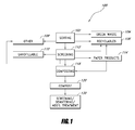
- FIG. 1 is a schematic flow chart of a solid waste handling, sorting and treatment system according to one embodiment that is arranged and configured in accordance with certain features, aspects and advantages of the present invention
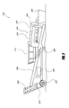
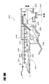
- FIG. 2 is a side elevation view of a trommel screen according to one embodiment that is arranged and configured in accordance with certain features, aspects and advantages of the present invention
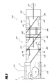
- FIG. 3 is a detailed side elevation view of the inlet hopper and screening drum of the trommel screen of FIG. 2 ;
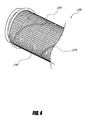
- FIG. 4 is a perspective view of a portion of the screening drum of FIG. 3 ;
- FIG. 5A is a detailed view of the screening surface of a drum according to one embodiment that is arranged and configured in accordance with certain features, aspects and advantages of the present invention
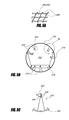
- FIG. 5B is a cross-sectional view of the screening drum taken along line 5 B- 5 B of FIG. 3 ;
- FIG. 5C is a detailed view of a knife member of the screening drum according to one embodiment that is arranged and configured in accordance with certain features, aspects and advantages of the present invention
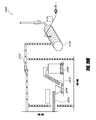
- FIG. 6 is a front elevation view of an in-vessel dewatering/composting apparatus according to one embodiment that is arranged and configured in accordance with certain features, aspects and advantages of the present invention
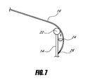
- FIG. 7 is a detailed cross-sectional view of the interface between the vessel body and the cover of the dewatering/composting apparatus of FIG. 6 taken along 7 - 7 ;
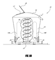
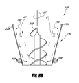
- FIG. 8A is a frontal elevation view of a dewatering/composting apparatus with a portion of the vessel body cut away to reveal an internal auger according to one embodiment that is arranged and configured in accordance with certain features, aspects and advantages of the present invention
- FIG. 8B is a frontal elevation view of a dewatering/composting apparatus with a portion of the vessel body cut away to reveal an internal auger according to another embodiment that is arranged and configured in accordance with certain features, aspects and advantages of the present invention
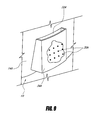
- FIG. 9 is a detailed perspective view of a liquid collection structure according to one embodiment that is arranged and configured in accordance with certain features, aspects and advantages of the present invention.
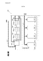
- FIG. 10 is a cross-sectional view of a clarifier tank according to one embodiment that is arranged and configured in accordance with certain features, aspects and advantages of the present invention.
- FIG. 11 is a front elevation view of a dewatering/composting apparatus according to another embodiment that is arranged and configured in accordance with certain features, aspects and advantages of the present invention.
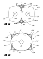
- FIG. 12A is a bottom view of the dewatering/composing apparatus of FIG. 11 ;
- FIG. 12B is a bottom view of a dewatering/composting apparatus according to another embodiment that is arranged and configured in accordance with certain features, aspects and advantages of the present invention.
- FIG. 12C is a cross-sectional view of the dewatering/composting apparatus of FIG. 12B , taken along 12 C- 12 C;
- FIG. 13A is front elevation view of a dewatering/composting apparatus with a portion of the outer sleeve cut away to reveal the main vessel wall according to still another embodiment that is arranged and configured in accordance with certain features, aspects and advantages of the present invention
- FIG. 13B is a cross-sectional view of the dewatering/composting apparatus of FIG. 13A , taken along 13 B- 13 B;
- FIG. 14A is a top view of a dewatering/composting apparatus comprising two internal augers according to one embodiment that is arranged and configured in accordance with certain features, aspects and advantages of the present invention
- FIG. 14B is a top view of a dewatering/composting apparatus comprising a single internal auger according to one embodiment that is arranged and configured in accordance with certain features, aspects and advantages of the present invention
- FIG. 14C is a side elevation view of an internal portion of the dewatering/composting apparatus of FIG. 14A , taken along 14 C- 14 C;
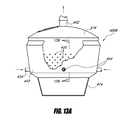
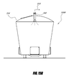
- FIG. 15A is a front elevation view of a dewatering/composting apparatus with a portion of its cover portion cut away to reveal an odor control system according to one embodiment that is arranged and configured in accordance with certain features, aspects and advantages of the present invention
- FIG. 15B is a front elevation view of a dewatering/composting apparatus configured to be connected to an odor control system according to another embodiment that is arranged and configured in accordance with certain features, aspects and advantages of the present invention
- FIG. 15C is a cross-sectional view of an odor control system configured to treat the fluid discharged from a dewatering/composting apparatus according to one embodiment that is arranged and configured in accordance with certain features, aspects and advantages of the present invention
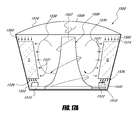
- FIG. 16A illustrates an elevation view of a dewatering/compositing apparatus with a portion of an outer sleeve cut away to reveal the main vessel wall according to one embodiment
- FIG. 16B illustrates a bottom view of the lower surface of the dewatering/composting apparatus of FIG. 16A ;
- FIG. 16C illustrates a cross-sectional view of the main vessel wall of the dewatering/composting apparatus of FIG. 16A ;
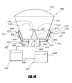
- FIG. 17A illustrates a cross-sectional view of a dewatering/composting apparatus according to one embodiment
- FIG. 17B illustrates a top view of the dewatering/composting apparatus of FIG. 17A ;
- FIG. 17C illustrates a side view of the wing portion of the auger of the dewatering/composting apparatus of FIG. 17A ;
- FIG. 17D illustrates an interior elevation view of the dewatering/composting apparatus of FIG. 17A ;
- FIG. 17E illustrates a cross-sectional view of the sidewall of the dewatering/composting apparatus of FIG. 17A ;
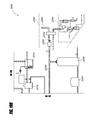
- FIG. 18 schematically illustrates a dewatering/composting apparatus comprising downstream treatment processes in accordance with one embodiment
- FIGS. 19A-19D illustrate a schematic process flow diagram for treating solid and liquid waste and providing odor control according to one embodiment that is arranged and configured in accordance with certain features, aspects and advantages of the present inventions.
- FIG. 1 schematically illustrates a solid waste treatment system 100 in accordance with one embodiment of the present inventions.
- the system 100 can comprise an initial sorting step 102 during which waste items may be separated into different bins.
- the sorting can be accomplished by waste producers, such as, for example, residential households, restaurant facilities, factories, other businesses, schools and the like. Waste producers can be provided with two or more different bins into which waste items may be placed according to type. Alternatively, waste sorting can be performed by personnel at waste sorting facilities and/or the like.
- solid waste is a broad term and may include, without limitation, municipal waste, industrial waste, sludge, fertilizer, manure, dairy waste, food waste, high moisture solid waste, low moisture solid waste, slurry and/or the like.
- many of the embodiments disclosed herein refer specifically to a composting apparatus. It will be appreciated, however, that such apparatuses can also be used to dewater the materials situated therein, either in lieu of or in addition to composting.
- the term “digester” is a broad term and is used in accordance with its ordinary meaning and may include, without limitation, any vessel, tank or other apparatus that is configured to dewater and/or treat, whether biologically (e.g., aerobic degradation, anaerobic degradation, anoxic degradation, etc.) or non-biologically, a volume of solids, liquids and/or other materials placed therein.
- biologically e.g., aerobic degradation, anaerobic degradation, anoxic degradation, etc.
- non-biologically e.g., a volume of solids, liquids and/or other materials placed therein.
- the terms “composting apparatus,” “composter,” “digester,” “dewatering/composting apparatus” and “digestion apparatus” are used interchangeably herein.
- recyclable 106 , green 104 and/or other waste types 108 can be handled differently from the remaining solid waste volume.
- recyclables 106 may be sent to a recycling center while green waste 104 can be used as landfill cover, for other land application purposes and/or the like.
- unsorted waste such as, for example, waste materials placed in non-compartmentalized municipal waste bins
- screening 112 can comprise a trommel screen, hand sorting and/or other devices or methods that further separate the waste into two or more different categories (e.g., type, size, etc.).
- unsorted waste can include a compostable waste portion, which may undergo composting during a subsequent composting step 118 , and another waste portion, which may be include landfillable materials 110 , recyclables 106 , larger paper products 114 (e.g., cardboard, paper packaging, etc.) and/or other waste materials 108 .
- larger paper products 114 e.g., cardboard, paper packaging, etc.
- the treated compost 120 may undergo further treatment, such as, for example, screening, dewatering and/or the like 130 .
- further treatment such as, for example, screening, dewatering and/or the like 130 .
- treatment methods or systems can include different and/or more or fewer treatment steps or processes.
- FIG. 2 illustrates a trommel screen 200 configured for placement upstream of a composting unit (not shown).
- the trommel screen 200 can comprise an inlet hopper 210 , a screening drum 230 , one or more conveyor systems 280 , 284 and/or one or more other features.
- waste material placed within the inlet hopper 210 can move into the interior of the rotating screening drum 230 .
- Materials passing through the openings of the screening drum 230 can be configured to fall onto a conveyor 280 or other collection system, which can then transfer the screened material away from the screening drum 230 .
- a conveyor 280 that is positioned underneath the screening drum 230 can be inclined at a particular angle 286 relative to horizontal so that the screened material can be simultaneously moved upwardly my the moving conveyor.
- the screening system can include a second conveyor 284 configured to receive the waste material carried by the first conveyor 280 .
- This can permit screened waste to be moved toward a different direction and/or to another general area.
- a chute 282 or other channeling device can be used to facilitate the transfer from the first conveyor 280 to the second conveyor 284 .
- one or more other methods or apparatuses can be used to move the screened waste from one location to another.
- the system can be operated under a batch mode in which screened waste is collected in a bin and subsequently moved to a desired location by a truck or other vehicle. It will be appreciated that any other method or device for moving waste can be used.
- waste materials that do not pass through the openings of the screening drum 230 can move to the outlet end of the screening drum 230 , where they may be deposited into a bin 300 or other container.
- this fraction of waste can be landfilled or subjected to additional sorting and/or treatment.
- larger cardboard items, similar paper products or other compostable materials may be separated for later placement into a composting unit.
- glass, aluminum, plastic and/or other materials can be separated for recycling purposes.
- the trommel screen 200 includes one or more motors 290 which can be used to operate the conveyors 280 , 284 , 216 , to rotate the screening drum 230 and/or drive one or more other mechanical and/or electrical components. Further, the trommel screen 200 can include wheel assemblies 292 or the like that facilitate in its transportation from one location to another.
- FIG. 3 illustrates a side view of the inlet hopper 210 and the screening drum 230 of the trommel screen 200 shown in FIG. 2 .
- the bottom of the inlet hopper 210 comprises an inlet hopper conveyor 216 that can be configured to deliver waste items W from the inlet hopper 210 toward the screening drum 230 (in a direction from left to right as shown in FIG. 3 ).
- Waste items can be deposited directly into an interior portion 212 of the inlet hopper 210 by a truck or other waste collection vehicle (not shown).
- the waste items can be first processed at a sorting station or other facility before being placed into the trommel screen 200 .
- one or more mechanical devices can be used to facilitate the placement of waste items into the inlet hopper 210 .
- a conveyor belt, an elevator, a vehicle equipped with a lifting member (e.g., bulldozer, front loader, etc.) or other lifting device can be used to deliver waste items into the inlet hopper 210 .
- a lifting member e.g., bulldozer, front loader, etc.
- other lifting device can be used to deliver waste items into the inlet hopper 210 .
- one or more interior portions of the inlet hopper interior 212 can be cushioned.
- one or more interior surfaces of the inlet hopper 210 can include a foam pad, a coating (e.g., polyurethane, elastomeric, etc.) and/or the like.
- the inlet hopper conveyor 216 can be configured to provide the necessary cushion and/or flexibility in order to reduce the likelihood that glass and other materials will break upon placement in the inlet hopper 210 .
- the conveyor 216 can include a thick rubber layer and/or can be configured to resiliently move downward in response to a vertical load. The location, thickness, durability, resiliency and other properties of the pad, coating or other protective member can be advantageously selected to reduce the possibility of breakage or other undesirable damage.
- the inlet hopper conveyor 216 can be configured to transfer waste items from the inlet hopper 210 to the interior of the screening drum 230 .
- the waste items enter the interior of the screening drum 230 through an outlet 218 of the inlet hopper 210 .
- the surface of the screening drum 230 can include a plurality of openings through which certain waste items may pass.
- the screen openings of the screening drum 230 can be created or formed using one or more suitable methods. For example, as illustrated in FIG. 5A , interwoven metal mesh 248 or wire can be shaped into the desired cylindrical shape.
- the screening drum 230 can comprise holes, perforations or other openings.
- the size of the openings can be chosen according to the particular application and/or desired screening size range. In some embodiments, the size of the openings remains consistent throughout the entire length of the screening drum 230 . Alternatively, the size of the openings can vary. In other embodiments, one or more portions of screening drum 230 need not have openings at all.
- the size of the openings 250 , 252 vary along the length of the screening drum 230 .
- the screen openings 250 can be approximately 2 inches by 2 inches.
- the screen openings 252 can be larger, such as, for example, approximately 4 inches by 4 inches. It will be appreciated that the screen opening sizes can be larger or smaller than disclosed and illustrated herein.
- the change in opening size along the length of the drum 230 can also vary.
- a varying screen opening size along the length of the screening drum 230 can further facilitate sorting of waste. For example, in FIG. 3 , smaller waste materials can pass through the screen openings 250 during an upstream portion 236 of the drum 230 . As discussed, this fraction of the waste can be collected by a conveyor 280 ( FIG. 2 ) and transferred to subsequent handling and/or treatment steps. Consequently, larger waste materials can remain within the interior of the drum 230 and move toward the drum outlet 231 .
- the screening drum 230 can comprise additional areas or zones with openings of varying sizes to further facilitate and enhance the sorting of waste.
- the drum 230 can include a solid section 240 that lacks openings.
- a section 240 may comprise small perforations or other openings that permit primarily only liquids (e.g., water, leachate, etc.) to pass through the drum 240 .
- larger waste items retained within the screening drum 230 can be hand sorted into various categories (e.g., recyclable, aluminum, glass, paper, etc.) at or near this solid section 240 .
- such large waste items can be discharged onto a conveyor or into a bin 300 or another container positioned beneath the outlet 231 of the screening drum 230 .
- Waste captured in such bins or containers can be further sorted or treated, as desired.
- cardboard and other paper-based products capable of being composted can be separated and subsequently fed into one or more shredders, composting units and/or the like.
- one or more flanged joints 244 , 246 or other types of connections can be used to join the different sections of the screening drum 230 .
- Other attachment methods can also be used, either in lieu of or in addition to flanged connections.
- drum sections can be attached using welds, fasteners, slip fittings, threads and/or the like.
- the screening drum 230 can be a unitary member that may or may not include variations in screen size along its length.
- the screening drum 230 can be sloped to facilitate the movement of larger items retained within the interior of the drum 230 towards the drum outlet 231 .
- the movement of the waste items through the drum 230 may also be aided by the rotation of the drum 230 .
- the slope and/or the rotational speed of the screening drum 230 can be easily varied as required or desired by a particular user.
- the screening drum 230 can include one or more reinforcing ribs 260 or other structural members.
- the illustrated trommel screen 200 comprises two circumferential reinforcing ribs 260 along the drum 230 .
- the reinforcing ribs 260 can have a different position, size, shape, orientation and/or general configuration than shown in FIG. 3 .
- the ribs 260 can be generally circumferential, longitudinal or diagonal (e.g., any angle in between longitudinal or diagonal).
- the reinforcing ribs 260 can be flat metal bars that are shaped to match or substantially match the shape of the inner or outer diameter of the screening drum 230 .
- the bars can be welded, fastened or otherwise attached to the inside and/or the outside surface of the drum 230 .
- One or more factors can be considered in determining whether or not reinforcing ribs 260 or other structural members are needed or desired, such as, for example, the diameter, length, thickness, materials of construction and other characteristics of the screening drum 230 , the anticipated size, volume, weight and other characteristics of the waste entering the drum 230 , the anticipated rotational speed of the drum 230 and the like.
- the screening drum 230 can comprise one or more internal channeling members 270 that are configured to help reduce the likelihood that glass and other impact-sensitive waste items will break during operation of the drum 230 .
- the channeling members 270 can include rigid or semi-rigid flat bars or the like (e.g., manufactured from steel, iron, other metals, polymeric materials, other composites, etc.) that are positioned along an interior portion of the screening drum 230 .
- the width and thickness of the bars can be approximately 1-2 inches and 1 ⁇ 4 inches, respectively. However, in other embodiments, the width and/or thickness of the bar can be smaller or larger, as desired or required by a particular application.
- the channeling members 270 can be shaped and otherwise configured to generally match the internal surface of the drum 230 . As illustrated in FIGS. 3 and 4 , the channeling members 270 can be routed along the interior of the drum 230 in a spiral fashion, such that the position of the channeling members 270 relative to the drum's circumference changes along the length of the screening drum 230 . Thus, in such arrangements, the channeling members 270 are positioned at an angle 272 relative to the longitudinal axis of the drum 230 .
- One or more suitable connection devices and/or methods can be used to attach the channeling members 270 to the drum 230 , such as, for example, welds, fasteners, adhesives or the like.
- the channeling members 270 can include any other type of rigid or semi-rigid article. In addition, more or fewer channeling members 270 can be used in a particular screening drum 230 . Further, the number, size, shape, dimensions, angle 272 , connection methods and other characteristics of the channeling members 270 can be different than that disclosed or illustrated herein.
- the channeling members 270 can help prevent glass and other impact-sensitive waste items from breaking by causing the waste items to move in a generally smoother manner through and within an interior portion of the screening drum 230 .
- the channeling members 270 may lessen the frequency that glass items positioned along an upper portion of the interior of the drum 230 abruptly fall to a lower portion of the drum 230 .
- the channeling members 270 can allow waste items to move in a more methodical manner along the length of the drum so as to reduce the impact between different waste items and/or between waste items and the surfaces of the drum 230 .
- the interior surface of the screening drum 230 can include one or more layers of a protective coating.
- the coating can help reduce the likelihood that glass and other impact-sensitive waste materials will break when they impact the surface of the screening drum 230 .
- the coating can include one or more layers of polyurethane, enamel, epoxy, plastic, paint and/or the like.
- the thickness of the coating can be varied depending on the particular application. For example, in some embodiments, the coating can be between 1/32 inch to 1 ⁇ 4 inch thick. However, the thickness of the coating can be larger or smaller than this range, as desired or required by a particular situation. In addition, such coatings can advantageously extend the effective life of screening drums 230 by providing anti-corrosion, anti-abrasion and other benefits.
- the screening drum 230 can comprise one or more bag rippers 310 or similar members. As shown, in some embodiments, the bag rippers 310 can be positioned near the outlet 218 of the inlet hopper 210 . In the depicted arrangement, the drum 230 includes a total of six bag rippers 310 . However, the drum 230 can comprise more or fewer bag rippers 310 .
- the bag rippers 310 can have the same size, shape, dimensions and general configuration. Alternatively, the bag rippers 310 can have one or more characteristics (e.g., shape, size, position, etc.) that distinguish them from each other. For example, as illustrated in FIG. 5B , some of the rippers 310 can be larger than others.
- the bag rippers 310 can be positioned along the same or different longitudinal location of the screening drum 230 . In addition, as shown herein, the bag rippers 310 can be situated along different circumferential locations of the drum 230 . Regardless, it may be desirable to include one or more bag rippers 310 immediately downstream of the inlet hopper outlet 218 ( FIG. 3 ) so that trash bags (e.g., plastic, paper, etc.) and/or other containers can be punctured to advantageously release the waste contents contained therein onto the screening drum 230 . This ripping process can be further facilitated by the rotational movement of the screening drum 230 relative to the inlet hopper 210 .
- trash bags e.g., plastic, paper, etc.
- the bag rippers 310 can be manufactured from one or more rigid and durable materials, such as, for example, steel, iron, other metals, composites and the like.
- the bag rippers 310 can be securely attached to the adjacent screening drum 230 using one more connection methods or devices, such as, for example, welds, fasteners and/or the like. Further, the bag rippers 310 can be permanently or removably attached to the drum 230 . Removable rippers 310 can advantageously permit a user to replace dull or otherwise damaged bag rippers 310 .
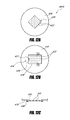
- one or more of the bag rippers 310 can include a blade 320 along their upper portion.
- the blade 320 comprises one or more sharpened surfaces 324 that facilitate the grabbing, ripping and/or cutting of the bags or other containers placed within the drum 230 .
- the blade 320 is attached to the bag ripper 310 using two removable fasteners 326 (e.g., screws, rivets, etc.). This can facilitate the replacement of the blades 320 as they blunt, break, bend or otherwise become damaged. Other removable and/or fixed connection methods can also be used to attach the blade 320 to the rippers 310 .
- the bag rippers 310 can be oriented so that their blades 320 face in different directions. Alternatively, the bag rippers 310 can be positioned so that the blades 320 are similarly configured. In addition, a bag ripper 310 may include two or more blades 320 to further facilitate the grabbing or cutting action. The shape, size and/or other characteristics of the blades 320 , as well as the position of the blades 320 relative to the bag rippers 310 , can be different that discussed and illustrated herein.
- the embodiments described herein can help enhance the composting of organic and other biodegradable materials. Consequently, by implementing such apparatuses and methods, or variations thereof, a higher quality and more consistent compost can be produced within a shorter time period. In addition, significant environmental benefits can be achieved because the total volume of waste directed into volume-limited landfills and other similar disposal sites can be reduced. In some embodiments, the nutrient-rich compost can be land applied and/or used in other beneficial or non-beneficial applications.
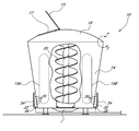
- FIG. 6 illustrates an in-vessel composting unit 10 comprising a main vessel portion 14 and a cover 16 .
- the depicted vessel portion 14 has generally rounded walls that taper inwardly toward the bottom of the composting unit 10 .
- the vessel portion 14 can comprise a generally cylindrical (e.g., vertical walls, wall being angled relative to vertical, etc.), frusto-conical, curved and/or the like. This applies to all embodiments of composting/dewatering units disclosed and illustrated herein.
- the composting unit 10 includes a sediment hopper 21 which is preferably positioned at a low point within the interior of the vessel portion 14 .
- the sediment hopper 21 which is configured to receive sand, grit and/or other coarse materials, can include a drain or cleanout (not shown) to facilitate emptying.
- the vessel portion 14 comprises one or more rigid materials capable of withstanding corrosion, abrasion, environmental conditions (e.g., rain, sunlight, etc.), fluctuations in temperature, pH, liquid level, internal pressure fluctuations and/or the like.
- the vessel portion 14 and/or other parts of the composting unit 10 may comprise steel, iron, concrete, fiberglass and/or any other suitable material.
- the composting unit 10 can be advantageously designed to resist wind, earthquakes and other forces that may act upon it.
- the vessel portion 14 can have a different general shape than disclosed or illustrated herein.
- the shape of the vessel portion 14 can be generally rectangular, egg-shaped, cylindrical and/or the like.
- the taper of the vessel's outer wall can be different than illustrated herein.
- the taper angle can be greater or less than illustrated and/or can include a different shape or orientation.
- the walls of the vessel portion 14 are substantially vertical.
- the composting unit 10 can include wheels (not shown) or may be configured to be positioned on a movable member (e.g., flatbed truck, trailer, etc.) for easy transport or relocation.
- the vessel portion 14 can include one or more hatches 18 or accessways.
- a rectangular shaped hatch 18 is located near the bottom of vessel portion 10 , close to the sediment hopper 21 .
- the hatch 18 can be advantageously removed to provide access to the inside of the composting unit 10 for cleaning, maintenance and/or any other purpose.
- the hatch 18 or other opening can be sized for easy ingress into and egress out of the interior of the composting unit 10 .
- the hatch 18 can be connected to the wall of the vessel portion 14 using one or more attachment methods or devices, such as, for example, bolts, hinges, slide railings, flanges, other fasteners and/or the like.
- a gasket or other compressible member can be positioned between the hatch 18 and the vessel portion 14 to provide a better seal.
- the composting unit 10 includes a generally dome-shaped cover 16 that extends around the entire periphery of the vessel portion 14 .
- the cover 16 can have any other shape, such as, for example, flat, conical, concave, convex, frusto-conical, frusto-spherical and/or the like.
- the cover 16 can be constructed of one or more rigid, semi-rigid and/or flexible materials.
- the cover 16 comprises a generally durable thermoplastic material which is specially sized, shaped and otherwise configured to fit over the vessel portion 14 .
- the cover 16 can simply include a sheet, tarp, fabric or other material that is stretched around the top opening of the vessel portion 14 .
- the cover 16 can be manufactured from plastic, rubber, tarp, metal and/or any other materials.
- the composting unit 10 can comprise a frame (not shown) or other similar system to generally support the cover 16 . This can be especially useful if a flexible or semi-rigid cover 16 is used.
- the frame can include one or more rigid members that span either partially or completely across the upper opening of the vessel portion 14 .
- the frame can include a steel truss that is supported by the vessel portion 14 and helps maintain the cover 16 in a desired shape or orientation.
- the inside surface of the cover 16 can be roughened and/or can to include a layer having a generally high surface area.
- a layer of artificial turf or other material can be placed underneath the cover 16 .
- the layer can be attached to the cover 16 using adhesives, fasteners and/or any other connection method or device.
- a relatively high surface area layer can provide a medium on which bacteria and other microorganisms can grow.
- such microorganisms can become acclimated to consume or otherwise eliminate certain problematic compounds that may otherwise accumulate on the bottom surface of the cover 16 .
- sulfur gas released during the decomposition of the waste materials may form sulfuric acid on the bottom of the cover 16 .
- Such acidic materials can cause the cover 16 , vessel portion 14 and other components of the composting unit 10 to corrode, deteriorate or otherwise become damaged, especially over time.
- techniques that promote the presence of bacteria which are able to consume, biodegrade or otherwise alter these problematic compounds can be utilized to advantageously eliminate or reduce damage to the composting unit 10 .
- the roughened surface or high surface area layer e.g., artificial turf
- the cover 16 can include one or more cover openings 17 .
- a cover opening 17 can provide access to the interior of the composting unit 10 for feeding, venting, aeration, maintenance and/or the like.
- a lid member 15 is hingably attached to the cover 16 to selectively cover or expose the adjacent cover opening 17 .
- the lid member 15 can be attached to the cover 16 using a different type of connection method or device (e.g., sliding door or accessway).
- the lid member 15 may need to be completely separated from the cover 16 in order to expose the cover opening 17 .
- the cover opening 17 is shaped, sized, positioned and oriented to facilitate with the feeding of the composting unit 10 and/or any other activities.
- FIG. 7 illustrates one embodiment of the interface between the cover 16 and the vessel portion 14 of the composting unit 10 .
- the cover 16 can be positioned over a support, such as a spherical member 22 , located at or near the upper end of the wall of the vessel portion 14 . It will be appreciated that any other suitable support structure and/or shape can be used.
- the cover 16 is attached to an exterior area 26 of the vessel portion 14 using one or more connection methods or devices.
- a condensation collection member 24 can be situated in the gap 23 defined by the exterior of the vessel portion 14 and the interior of the cover 16 .
- a liquid collection member 24 can be configured to collect condensation and other liquids that collect on the cover 16 and flow (e.g., drip) downwardly along an interior surface of the cover 16 .
- one or more channels, grooves and/or other openings can be advantageously positioned between the spherical member 22 and the cover 14 to allow any liquid moving along the inside of the cover to enter the gap 23 .
- Water and other liquid collected by the condensation collection member 24 can be advantageously removed from the composting unit 10 using one or more pipes or other conveying members.
- the condensation collection member 24 can be positioned entirely or partially around the cover-vessel portion interface.
- the cover depicted in FIG. 7 comprises a flexible plastic sheet that stretches over the spherical member 22 and the condensation collection member 24 before it attaches to the vessel portion 14 .
- the sheet can attach to the vessel portion wall using one or more snap fit connections, hooks, clamps and/or using any other device or method.
- the spherical member 22 and/or the condensation collection member 24 comprise polyvinyl chloride (PVC), plastic, steel, copper, iron, other metals, composites and/or any other suitable material.
- the composting unit 10 does not need to include a condensation collection member 24 at all, allowing the liquid to simply roll down the outside surface of the vessel portion 14 .
- One or more other collection members or methods can be incorporated into the design of the composting unit 10 for the removal of condensation and/or other liquids.
- FIG. 8A illustrates a composting unit 10 similar to the one shown in FIG. 6 with a section of the vessel portion 14 removed to reveal an interior area.
- the interior of the composting unit 10 can comprise one or more augers 20 or other mixing members to allow the materials being processed to be selectively mixed or agitated.
- the auger 20 can also facilitate dewatering of waste while the composting unit 10 is being operated.
- a single auger 20 is positioned near the center of the composting unit 10 .
- the auger 20 is supported at or near the bottom floor of the vessel portion 14 and extends vertically toward the cover 16 .
- the position and orientation of the auger 20 within the composting unit 10 can be different than discussed and illustrated herein.
- the top of the auger 20 is positioned at or near the top of the vessel portion 14 .
- the auger 20 may extend to about halfway or more than halfway the height of the vessel portion 14 .
- the top of the auger 20 can be at or near three-fourths the total height of the vessel portion 14 .
- the auger 20 may extend below the halfway height of the vessel portion 14 .
- two or more augers 20 can be included within a single composting unit 10 .
- Augers 20 can have a vertical, horizontal, diagonal or any other orientation. If a composting unit 10 includes two or more augers 20 , the augers 20 can be parallel and/or non-parallel to each other.
- augers 20 within the same composting unit 10 can vary from one another with respect to length, shape and/or any other characteristics. Regardless of their exact size, dimensions, shape, positioning and location within the composting unit 10 , the augers 20 can be advantageously configured to rotate about a longitudinal axis.
- this rotating motion can facilitate the mixing and/or dewatering of the waste materials being treated within the unit 10 .
- the augers 20 are configured so that their rate of rotation can be modulated (e.g., increased, decreased), allowing operators to modify the composting operation in response to one or more factors or as otherwise desired.
- FIG. 8B illustrates another embodiment of a composting unit 10 B comprising an auger 20 B that is generally cone-shaped. As shown, the auger 20 B includes fewer threads than the auger depicted in FIG. 8A . However, in other embodiments, the auger 20 B can include more or fewer threads than illustrated in FIG. 8A or 8 B.
- the auger 20 B is configured to rotate in a clockwise direction when viewed from the top, as indicated by the arrow 23 .
- Rotation of the auger 20 B can cause the internal contents of the composting unit 10 B to move in a generally circular manner as illustrated by arrows 19 C, 19 D. This can help maintain the waste materials situated within the composting unit 10 B well-mixed.
- the downward movement of the solids next to the openings 30 B along the lower end of the vessel portion 14 B can facilitate dewatering of the solids.
- the dewatering also can be aided by the geometry of the vessel 14 B and/or the orientation of the auger 20 B relative to the walls of the vessel 14 B, as compression zones can be created at or near the bottom of the composting unit 10 B (e.g., near the openings 30 B).
- the downward force created by the head pressure (represented by arrows 21 ) of the solids contained within the composting unit 10 B can further enhance dewatering through the openings 30 B.
- the composting unit 10 can optionally comprise an aeration system for providing air into the interior of the unit 10 during operation.
- some microbes or other microorganisms responsible for the composting process require oxygen to adequately and efficiently decompose the waste materials fed into the composting unit 10 .
- air or other fluid containing oxygen e.g., pure oxygen
- One or more blowers, air compressors or other fluid transfer devices can be used to deliver a desired air flow within one or more regions of the composting unit 10 .
- the air or other fluid can be conveyed to one or more discharge points through a piping system.
- air diffusers or similar air distribution members may be used to dispense air throughout an interior portion of the composting unit 10 .
- the interior of the composting unit 10 can be in fluid communication with the ambient environment during the composting process, such as, for example, by removing the cover or a portion of it (e.g., the cover's lid member 15 in FIGS. 6 and 8 A).
- This can permit air to enter the interior of the composting unit 10 and at least partially aerate the material (e.g., waste) contained therein.
- the composting can be operated under limited oxygen or no oxygen (e.g., anoxic, anaerobic, etc.). Such a change can affect the manner in which the composting unit is operated and/or the characteristics of the composed materials.
- heating and/or cooling devices can also be included to generally control the temperature within the interior of the composting unit 10 .
- microbes and other microorganisms are most efficient when the surrounding temperature is within a particular target temperature range. For example, certain microorganisms prefer relatively cold environments, such as, for example, environments where temperatures are near or below 25° C. Other microorganisms are most active in relatively moderate temperature ranges, such as, for example, temperatures between 20° C. and 45° C. Yet other microorganisms exhibit optimum growth rates in relatively warm environments, such as, for example, environments where temperatures are near or above 45° C. or greater. Typically, heat is a by-product of the composting process.
- Temperature control devices can include heaters, heating/cooling channels, heat exchangers and the like.
- the composting unit 10 can comprise temperature sensors, control units and/or other components.
- the vessel portion 14 can comprise a plurality of openings 30 along one or more of its walls.
- the openings 30 which are in fluid communication with the inside of the composting unit 10 , are located near the bottom of the vessel portion 14 .
- the number, shape, size, location, spacing and/or other characteristics of the openings 30 can be customized to the particular composting procedure being performed.
- the openings 30 which are configured to discharge water and other liquids contained within the vessel portion 14 , are circular and have a diameter of approximately 1 ⁇ 2 inch.
- the openings 30 may be configured to permit air to enter into and/or exit from the interior of the vessel portion 14 under certain desired conditions.
- the openings 30 can be smaller than 1 ⁇ 2 inch, such as for example, 1 ⁇ 8 inch, 1/16 inch, 1/32 inch or smaller, or ranges encompassing such values.
- the openings 30 can be larger than 1 ⁇ 2 inch, such as for example, 3 ⁇ 4 inch, 1 inch, 11 ⁇ 2 inch, 2 inch or greater, or ranges encompassing such values.
- the vessel portion 14 may comprise openings 30 having two or more different shapes, sizes or other characteristics.
- the openings 30 can be shaped, sized, positioned, spaced and/or otherwise configured according to the type of waste material that will be placed within the composting unit 10 or as otherwise is desired by the user. For example, it may be desirable to include relatively smaller openings if biosolids, primary sludge, secondary sludge, digested sludge or other materials generated by a wastewater treatment facility are to be treated. This can help reduce or prevent the undesirable movement of waste materials through the openings 30 .
- a collection area 32 can be defined by a collection structure 34 positioned on the outside of a vessel portion wall, on the inside of a vessel portion wall and/or embedded in the wall of the composting unit.
- the collection structure 34 comprises a box-like member formed by one or more rigid or semi-rigid members.
- the collection structure 34 can be formed by welding two or more steel plates to one another.
- the collection structure 34 may be advantageously shaped to generally match or otherwise complement the exterior shape of the vessel portion 14 to which it attaches.
- the collection structure 34 can be permanently or temporarily attached to the vessel portion.
- the collection structure 34 can be removably attached to the vessel portion 14 using one or more connection methods or devices, such as, bolts, slide fittings, clips, clamps, other fasteners and/or the like.
- the collection structure 34 may be formed from the same unitary body as the composting unit 10 (e.g., using welds or the like).
- FIG. 9 illustrates another embodiment of a collection structure 34 A positioned along the outside of a vessel portion 14 A.
- a portion of the collection structure 34 A is removed to reveal a number of openings 30 A on the vessel portion 14 A.
- the collection structure 34 A preferably defines a collection area 32 A into which the openings 30 will discharge. Thus, liquid exiting a composting unit 10 can be captured and collected within the collection area 32 A.
- the collection structure 34 can comprise a drain 36 or other outlet which allows the collected liquid to be easily removed.
- a composting unit 10 can comprise one, two or more collection structures 34 .
- a vessel portion 14 includes four collection structures 34 , each of which is advantageously spaced to provide more efficient removal of water and other liquids from the adjacent composting unit 10 .
- the collection structure 34 is completely or partially sealed off from the atmosphere. This may be significant for odor control purposes, especially if the liquid or other fluids discharged from the openings 30 are malodorous.
- the collection area 32 can be open or selectively openable (i.e., completely or partially sealable) to the surrounding environment.
- One or more openings 30 may be positioned on the underside of the vessel portion 14 , either in lieu of or in addition to any openings 30 located on the sidewalls. Therefore, in order to collect the volume of liquid discharged from the composting unit 10 , it may be desirable to include a collection structure or similar member along the bottom and/or in any other area of the composting unit 10 that comprises an opening.
- liquid discharged into the collection structures 34 can be directed into an interconnected piping system 38 .
- the piping system 38 which in some embodiments includes one or more fittings (e.g., tees, elbows, valves, etc.), can be configured to channel liquid to another location for disposal, treatment and/or further processing.
- the piping system 38 can comprise steel, PVC, plastic, copper, galvanized steel, iron, ductile iron, rubber and/or other suitable material.
- liquid is transferred from a collection structure 34 to a clarifier tank 40 or another treatment process.
- the liquid can be configured to flow by gravity from a collection structure 34 to the clarifier tank 40 or other treatment step to reduce or eliminate the need for pumps or other mechanical devices.
- liquid from the collection structures can be discharged into a sewer, drain and/or the like.
- the clarifier tank 40 includes an inlet 51 through which liquid is discharged. It will be appreciated that a clarifier tank 40 can include additional inlets 51 .
- the tank 40 can comprise a screen 42 , membrane and/or other separation member that is used to remove solids from the liquid stream or otherwise treat the liquid being discharged into the tank 40 .
- a lower outlet 54 can be provided downstream of a screen 42 , allowing the some or all of the solids contained in the liquid that passes through the screen 42 to be separated or removed.
- the clarifier tank 40 may not include a screen 42 or other physical separation member.
- liquid can be directed into the tank 40 and can be given sufficient time to naturally separate into one or more layers. For example, over time, the heavier solids contained within the liquid stream may settle towards the bottom of the clarifier tank 40 . Further, grease, oil and other substances having a lower density may float toward the top of the liquid level. Consequently, a plurality of outlets 52 , 53 , 54 can be positioned along various heights of the tank 40 to permit selective removal of one or more different types of liquid or solids. In other embodiments, a series of such tanks 40 can be provided.
- the clarifier tank 40 includes a total of three outlets 52 , 53 , 54 positioned at different elevations.
- the bottom outlet 54 can be used to remove sludge, solids or other heavier materials that have settled toward the bottom of the tank 40 .
- An upper outlet 52 can be configured to remove oil, grease and other floatable materials.
- the middle outlet 53 can be used to remove water and/or other liquids retained near the middle portion of the tank 40 . It will be appreciated that more or fewer outlets may be included, and that the size, shape, spacing, location, general configuration and/or other details about the outlets can be different than discussed and illustrated herein.
- the tank 40 can comprise a mixer, aerator, chemical injectors, baffles and/or the like.
- the clarifier tank 40 can be operated either as a batch or a continuous system. Further, the operation of the tank 40 , including filling, emptying, etc., can be automatic or manual.
- the treated water can be re-introduced into the composting unit 10 , especially at later stages of the composting process, in order to maintain a desired moisture level for the waste materials being treated therein.
- liquid discharged from the tank 40 can be directed to a drain or another location. In some embodiments, the treated liquid may be used as washwater and/or for other non-portable purposes.
- the clarifier tank 40 comprises one or more rigid or semi-rigid materials, such as, for example, plastic, steel, iron, aluminum, other metals or composite materials and/or the like.
- the size, shape, dimensions, capacity, location of inlets and outlets and other characteristics of the tank 40 may be varied, as desired or required by a particular user or application.
- the clarifier tank 40 can also be configured to accept other liquid waste, such as, for example, condensation and/or other liquids directed into the condensation collection member 24 ( FIG. 7 ).
- the composting unit 10 can be operated as either a batch or a continuous system. Under a batch operation mode, organic materials and/or other waste items are fed into the composting unit 10 at the beginning of a composting cycle and are not removed until the composting cycle ends. It will be appreciated that additional items, such as liquid discharged from the openings, liquid collected in the clarifier tank, cardboard items and the like, may be added at later stages of a composting cycle. Typically, however, waste is not continuously added into or removed from the composting unit 10 under such an operational scheme. Conversely, the composting unit 10 can be operated under a continuous mode where waste material is constantly or intermittently fed into the composting unit 10 , and composted waste is constantly or intermittently removed from it.
- a volume of organic material and/or other compostable waste is initially fed into the composting unit 10 through a cover opening 17 as depicted in FIG. 6 .
- the cover 16 may be removed, either partially or completely, before initiating the feeding of the composting unit 10 .
- the cover 16 can be placed over the vessel portion 14 to seal the unit 10 .
- any such openings can be selectively closed.
- one or more augers 20 located in the composting unit 10 begin operating as the composting unit 10 is being filled.
- the augers 20 may be initiated immediately after the filling phase has been completed or at some other time (e.g., after a prescribed time period following initiation of the composting process has elapsed).
- the rotational speed of each auger 20 can be adjustable.
- the augers 20 may be operated continuously or intermittently during the composting process.
- a volume of water and/or other liquid can be removed from the composting unit 10 through the plurality of openings 30 located on the vessel portion 14 . Removal of water and/or other liquids from the waste materials, and thus the composting unit 10 , can be facilitated by operation of an auger 20 . In some embodiments, movement of the solids and other waste materials resulting from the operation of the augers can increase the amount of water and/or other liquids that are removed from a composting unit through the openings. Moreover, the weight of the material within the composting unit 10 can lead to additional dewatering through the openings 30 .
- the composting process is more efficient when the water content of the materials within the unit 10 is within a desired range, it is often beneficial to initially remove a particular volume of water and/or other liquids.
- water and/or other liquids may be added to the composting unit 10 to achieve a desired moisture level.
- water collected, and possibly treated, in a clarifier tank 40 can be returned to the composting unit to control the moisture level.
- the temperature inside the composting unit 10 may naturally rise due to the increased microbial activity.
- the temperature can be artificially regulated (e.g., heated, cooled, etc.) using a heating and/or cooling device.
- air or other oxygen-bearing fluids can be directed into the composting unit 10 to facilitate the microorganisms in their decomposition of the waste materials.
- additional water and/or other liquids can exit the composting unit 10 via the openings 30 . This can result from one or more reasons, such as, for example, the physical, chemical, biochemical and/or other properties of the waste materials being treated, the fluid mechanics inside the vessel portion and/or the like.
- the augers 20 help to maintain the compostable materials well-mixed during the decomposition process.
- operation of the auger 20 can cause the waste materials within the composting unit 10 to move in a pattern generally represented by arrows 19 A and 19 B.
- the mixing patterns and characteristics of a composting unit 10 may depend on one or more factors, such as, for example, the shape, size, dimensions, orientation or other features of the composting unit, including the augers, the viscosity, density, water content and other properties of the materials being processed and/or the like.
- the composting unit can be operated for a minimum time period before it is stopped.
- this time period ensures that the waste materials are treated to a level that meets or exceeds the applicable regulatory and/or other applicable requirements.
- an EPA or other regulatory agency requirements may necessitate that a minimum percentage of organic material decomposition to be attained before the composted materials can be land applied.
- a governing regulation can mandate that a particular time-temperature treatment option be achieved.
- such regulations can be achieved by operating the composting unit 10 for approximately seven days under a mesophilic temperature range (e.g., between 0° and 45° C., or more preferably, between 20° to 35° C.).
- a mesophilic temperature range e.g., between 0° and 45° C., or more preferably, between 20° to 35° C.
- the compostable materials may need to be processed for longer or shorter time periods and/or at higher or lower temperatures than disclosed herein.
- additional organic and/or other waste materials can be added to the composting unit 10 .
- cardboard or other large paper-based products can be fed into the composting unit 10 through one or more openings.
- Other organic or other waste materials can also be added into the composting unit 10 , either in lieu of or in addition to paper-based waste, after the composting cycle has commenced.
- waste materials Under a continuous feed operational mode, waste materials can be fed into, and consequently can be removed from, the composting unit 10 at one or more regular intervals.
- the addition of organic materials while the composting unit 10 is operating can be used to control the carbon to nitrogen ratio, the food to microorganism ratio and other operational parameters or factors that can affect the composting process.
- a volume of water or other liquid can be added to the composting unit 10 to maintain the moisture content within the unit 10 within a desired range. Polymers and/or other chemicals may also be added to further enhance the composting process.
- the composting unit can be used to treat different types of solid and/or liquid waste streams.
- the composting unit can be used to treat municipal and/or industrial sludge (primary sludge, secondary/biological sludge, waste activated sludge, digested sludge, etc.).
- the composting unit can also be used to treat manure or other solid and/or liquid wastes originating from animal farms and the like.
- the auger 20 , air feed system and/or other systems or subsystems can be stopped.
- the treated compost can then be removed from the composting unit 10 for further processing or treatment, packaging, transport and/or the like.
- the treated compost can be screened to remove larger items.
- the treated compost can be dewatered, chemically or biologically treated and/or the like.
- the compost can be removed from the vessel portion 14 using a solids pump (e.g., non-clog centrifugal pump, solids submersible pump, diaphragm pump, piston pump or other device configured to move sludge and other viscous, thick or thixotropic materials).
- a solids pump e.g., non-clog centrifugal pump, solids submersible pump, diaphragm pump, piston pump or other device configured to move sludge and other viscous, thick or thixotropic materials.
- the suction of the pump or other mechanical device can be connected to a dedicated outlet fitting on the vessel portion 14 (not shown).
- the suction of the pump (or the pump itself if a submersible or similar pump is used) can be directly placed into the composting unit 10 .
- the suction of the pump can be placed through a cover opening 17 , a hatch 18 , other accessway or the like.
- the treated compost can be transferred out of the composting unit 10 without using a pump.
- the compost can be removed by simply scooping it out of the hatch 18 or the top of the vessel portion 18 after the cover 14 is removed or through one or more bottom or side openings.
- water or other liquid that enters the clarifier tank 40 or that is collected in a collection structure 34 , a condensation collection member 24 and/or the like can undergo some level of treatment.
- the liquid can pass through a screen or other separation membrane.
- the liquid can be allowed to naturally separate into two or more different layers.
- the liquid can undergo chemical and/or biological treatment. After the liquid has been treated, it can be selectively returned to the composting unit 10 (e.g., randomly, according to a timed manner, etc.) to maintain a desired moisture level.
- the liquid can undergo additional treatment, can be sewered, can be used in other processes and/or the like.
- solids or other materials removed from the liquid e.g., using a clarifier tank 40 , a subsequent process, etc.
- a composting unit 400 A includes a plurality of openings 420 positioned along the outside of a main vessel portion 414 .
- the openings 420 can be shaped, sized and otherwise configured to permit air or other fluid to enter the interior of the composting unit 400 A. This can be especially desirable if an aerobic composting process is being utilized to treat the waste materials fed into the composting unit 400 A.
- air or other fluid passing through the main vessel portion 414 can also improve the mixing characteristics within the interior of the composting unit 400 A.
- the composting unit 400 A includes or is in fluid communication with a suction pump or other vacuum source (not shown) in order to assist in drawing air or other fluid through the plurality of openings 420 located along the vessel portion 414 .
- a suction or vacuum source e.g., pump, compressor, etc.
- the outlet 402 e.g., ventilation passage
- a suction or vacuum source can be positioned downstream of the outlet 402 (e.g., ventilation passage).
- air can be drawn into the interior of the composting unit 400 A through one or more of the plurality of openings 420 .
- a suction or vacuum source can be positioned at one or more other locations (e.g., the interior of the composting unit 400 A), either in lieu of or in addition to a suction source at the downstream end of the outlet 402 .
- the openings 420 are located toward the vertical center of the main vessel portion 414 . Further, the openings 420 are arranged in a generally zigzag pattern. However, it will be appreciated that the quantity, location, spacing, general orientation and other characteristics of the openings 420 can vary from what is depicted in FIG. 11 and discussed herein. For example, the openings 420 can be dispersed over a larger area of the main vessel portion 414 and/or any other portion of the composting unit 400 A (e.g., the cover 416 , the bottom portion, etc.). In other embodiments, the main vessel portion 414 includes more or fewer openings 420 .
- the openings 420 comprise a generally circular shape having an approximate diameter of 1 ⁇ 8, 1 ⁇ 4, 1 ⁇ 2, 3 ⁇ 4 or 1 inches. In other embodiments, however, the size of the openings 420 can be lower than 1 ⁇ 8 inch, greater than 1 inch and/or within the above range (e.g., 1 ⁇ 8 to 1 inches). Alternatively, the openings 420 can include one or more other shapes, such as, for example, rectangular, triangular, other polygonal, elliptical, irregular or the like. Moreover, the diameter or other transverse dimension of the openings 420 can be greater or smaller than indicated above. Moreover, a composting unit 400 A can be configured so that the size, shape and/or other characteristics of the openings 420 vary from each other.
- openings 422 can be positioned along the bottom 418 of the composting unit 400 A. With reference to the bottom view illustrated in FIG. 12A , a plurality of openings 422 can be located within a rectangular region 430 , for example, near the center of the composting unit 400 A.
- the size, shape, location, spacing and other characteristics of the bottom openings 422 can be selected based on the particular use or application (e.g., the type of solids being composted, the water content of the compost, the target operating temperature, the target oxygen concentration within the composting unit 400 A, etc.).
- openings 422 can be located near the periphery of the bottom portion 418 , either in lieu of or in addition to the openings 422 disposed near the center as shown in FIG. 12A .
- the entire bottom portion 418 comprises openings 422 .
- the composting unit 400 A can be configured without any bottom openings 422 at all.
- the bottom openings 422 and/or the side openings 420 are configured to discharge fluids (e.g., water or other liquid) to the exterior of the composting unit 400 A.
- fluids e.g., water or other liquid
- such openings 420 , 422 can assist the composting process by desirably dewatering the solids being treated.
- the extent of dewatering through these openings 420 , 422 may depend on one or more factors, such as, for example, the size, shape and other details of the openings 420 , 422 , the type of solids being treated, the water content of the solids being treated, the operating temperature of the composting unit and/or the like.
- FIG. 12B illustrates an alternative embodiment of the bottom portion 418 of a composting unit.
- the openings 422 are located on a removable plate 436 which is slidably disposed within a receiving system 438 .
- the receiving system 438 can comprise outer angles or other members that are configured to receive a perforated plate 436 .
- the removable plate 436 can include a handle 437 or other grasping device to facilitate manipulation of the plate 436 (e.g., removal from the receiving system 438 , insertion into the receiving system 438 , general handling or maintenance, etc.).
- the plate 436 and the receiving system 438 can be manufactured from one or more durable materials (e.g., steel, stainless steel, cast iron, other metals, composite materials, etc.) which are configured to withstand the forces, moments, frictional resistance, chemical/biological environments, abrasive contact, wear and tear and/or other conditions to which they may be exposed.
- durable materials e.g., steel, stainless steel, cast iron, other metals, composite materials, etc.
- a removable bottom plate 436 can permit a user to conveniently modify the quantity, size, shape and/or other details of the bottom openings 422 .
- a plate 436 having more and/or larger openings 422 can be selected.
- a plate 436 with smaller and/or fewer openings 422 can be used. It will be appreciated that such removable systems can also be used along one or more other portions of the composting unit, such as, for example, the main vessel portion 414 or the cover 416 .
- air, oxygen or other fluids can be delivered into the interior of a composting unit by creating a suction or vacuum at an opening (e.g., the outlet end).
- air or other fluid can be forced across one or more composting unit walls as illustrated in FIG. 13A .
- the composting unit 400 B comprises an outer shell 450 that generally confines a space 452 around an area of the main vessel portion 414 .
- the shell 450 surrounds a plurality of openings 420 , each of which can be in fluid communication with the interior of the composting unit 400 B.
- the shell includes one or more inlets 454 through which air or other fluids can be delivered into the space 452 .
- the shell 450 extends circumferentially around the entire main vessel portion 414 . Further, the shell 450 covers only a fraction of the vertical portion of the composting unit 400 B. However, it will appreciated that the shape, size, dimension, location, distance from the main vessel portion 414 and other details of the shell 450 can be different than discussed and illustrated herein. For example, in some embodiments, the shell 450 covers substantially the entire outer surface of the main vessel portion 414 . Alternatively, the shell 450 can be smaller than shown in FIGS. 13A and 13B (e.g., the shell can extend only partially or intermittently around the periphery of the unit 400 B, can encompass a smaller height or vertical distance along the exterior portion of the unit 400 B, etc.).
- the number of inlets 454 or other connections that a shell 450 comprises can depend on one or more factors, such as, for example, the size of the space 452 , the number of openings 420 positioned along the main vessel portion 414 , the aerobic demand (e.g., required air flow into the interior of the composting unit 400 B), the fluid mechanics associated with such air flow (e.g., head losses) and/or the like.
- the shell 450 includes a total of four inlets 454 , which are equally spaced (e.g., 90 degrees) from each other.
- a shell 450 can include more or fewer inlets 454 as desired or required.
- an air compressor, pump or other positive pressure fluid delivery device can be connected to one or more of the inlets 454 of the outer shell 450 .
- air can be delivered into the space 452 defined by the shell 450 and an adjacent portion of the composting unit wall. Consequently, air delivered into the space 452 can enter the interior 406 of the composting unit 400 B through the plurality of openings 420 positioned along the main vessel portion 414 .
- pure oxygen or another fluid mixtures can be conveyed into the space 452 , either in lieu of or in addition to ambient air.
- the flowrate of air or other fluid passing through the inlets 454 , and thus, the openings 420 can be modified by modulating the discharge pressure of the compressor, pump or other fluid transfer device (not shown) and/or by using a valve or other flow or pressure regulating device.
- one or more oxygen sensors or the like can be advantageously positioned within the composting unit 400 B. This can assist a user to determine if more or less airflow is required.
- the air delivery system can be automated so that a substantially constant air flow in being delivered into and/or a desired oxygen concentration in maintained within the interior of the composting unit 400 B.
- air or other fluid After air or other fluid enters the composting unit 400 B, it can be used by microorganisms present therein for the aerobic digestion of the organic materials being treated. Excess air can flow upwards toward the cover 416 of the composting unit 400 B where it can be discharged through one or more outlets 402 . As discussed in greater detail herein with respect to odor control, fluid discharged through the outlet 402 can be treated using a biofilter, scrubber or other treatment device or method. Alternatively, all or a portion of the fluid discharged through the outlet 402 can be redirected into the space 452 through one or more shell inlets 454 .
- the composting unit 400 C includes two separate zones 406 A, 406 B, each of which comprises a mixing device 408 (e.g., an auger 408 ).
- a mixing device 408 e.g., an auger 408
- one or more interior baffle units 460 or other members can be used.
- the depicted composting unit 400 C includes two baffle units 460 which are shaped, sized, positioned and otherwise configured to effectively create a substantially circular zone around each auger 408 . It will be appreciated, however, that the zones surrounding each auger 408 or other mixing device can comprise a different size, shape and/or other characteristics.
- the baffle units 460 can also be used as fluid distribution devices to distribute air, oxygen or other fluids into the interior of the composting unit 400 C. Similar to the shell 450 discussed and illustrated herein with reference to FIGS. 13A and 13B , the baffle units 460 can comprise an interior space 452 . Air or other fluids can be delivered into the interior space 452 through one or more inlets 454 . In some embodiments, as shown in FIGS. 14A and 14C , at least a portion of the exterior surface 464 of a baffle unit 460 includes a plurality of openings 420 .
- baffle units 460 can be used to aerate the interior of a composting unit 400 C while simultaneously improving the mixing characteristics of the system.
- FIG. 14B illustrates another embodiment of a composting unit 400 D comprising interior distribution baffle units 460 .
- the depicted composting unit 400 D includes only a single auger 408 and a single mixing zone 406 .
- the distribution baffle units 460 can further improve the mixing characteristics of the vessel by reducing the size of or altogether eliminating dead zones within the interior of the unit 400 D.
- the composting unit 400 D comprises a total of four baffle units 460 , each of which is positioned along an interior corner of the composting unit 400 D.
- the baffle units 460 include an interior space 452 B which is in fluid communication with an interior 406 of the composting unit 400 D through a plurality of openings 420 .
- air or other fluid discharged into the interior space 452 B of a baffle unit 460 through one or more inlets 454 can be distributed into the interior 406 of the composting unit 400 D.
- Air distribution baffles positioned within the interior of a composting unit 400 C, 400 D can be used in lieu of or in addition to one or more exterior shells, such as those discussed in relation to FIGS. 13A and 13B .
- a composting unit can comprise or be integrated with an odor control system. It will be appreciated that any of the composting units disclosed or illustrated herein can be equipped with or be placed in fluid communication with such an odor control system.
- a composting unit 500 A can be configured to reduce or eliminate the amount of odorous gases (e.g., hydrogen sulfide, other sulfur-based gases, etc.) and other fluids that leak or otherwise escape from its interior 506 .
- the composting unit 500 A includes gaskets and/or other compressible or resilient members that properly seal hatches 518 , 517 , accessways or other openings of the unit 500 A through which odors and other gases can otherwise escape.
- other items or features of the composting unit 500 A such as, for example, collection structures 534 positioned along the main vessel portion 514 , can be advantageously configured to be air-tight or substantially air-tight.
- fluid within the interior 506 of the composting unit 500 A can generally move towards the cover 516 .
- the cover 516 can comprise an air treatment system 570 which is configured to advantageously treat a volume of gas (e.g., foul air) before it exits the composting unit 500 A into the surrounding environment.
- the air treatment system 570 includes biofilter media (e.g., activated carbon) positioned within the cover portion 516 of the composting unit 500 A.
- biofilter media e.g., activated carbon
- other waste air treatment technologies can be used either in lieu of or in addition to biofilter media.
- the biofilter media and/or other air treatment system 570 can be positioned in one or more other locations, either within or outside of the composting unit 500 A.
- the biofilter media is maintained within the cover portion 516 of the composting unit 500 A using a support structure 572 .
- the support structure 572 can comprise a plurality of rigid members, such as, for example, angles, channels, sheets, plates, trusses, beams, columns, platforms and/or the like.
- the various components of the support structure 572 can be constructed of stainless steel, other metals and metal alloys, fiberglass, aluminum and/or any other suitable material.
- the materials used in the manufacture of the support structure 572 are configured to withstand the weight and other forces to which they may be exposed during the operation of the composting unit 500 A.
- the support structure components are preferably configured to withstand the normal operating conditions within the composting unit 500 A, such as, for example, pH and pH fluctuations, corrosion, abrasion, temperature and temperature fluctuations and/or the like.
- biofilter media 574 comprises a high surface area material (e.g., plastic packing, plastic balls and other shapes, plastic peanuts, etc.).
- the biofilter media 574 is preferably shaped, sized and otherwise configured to promote the growth of microorganisms on its surface.
- the microorganisms can be generally anaerobic, aerobic and/or anoxic depending on how the composting unit is being operated. Once microorganisms grow and become established on the surface area of the biofilter media 574 , air flowing past the media 574 can be partially or completely treated.
- organic and/or inorganic pollutants and other substances present within the air can be transferred to the biofilter media 574 .
- the microorganisms can then degrade or convert these pollutants and other substances into inert materials or products which are less offensive or less undesirable.
- the treatment system can further include a collection member 580 which, in the illustrated embodiment, comprises a perforated pipe 580 or other conduit.
- a plurality of openings 582 on the pipe 580 are configured to receive the treated air or other fluid and deliver it to a downstream outlet pipe 584 .
- a pump or other fluid transfer device 590 positioned downstream of the perforated pipe 580 and the outlet 584 provides the necessary suction to remove the treated air from the interior 506 of the composting unit 500 A.
- Treated air or other fluid exiting the composting unit 500 A can be discharged to the atmosphere or can undergo additional conveying and/or treatment as needed or required.
- one or more other types of pollution control technologies can also be used to treat the air or other fluid before it is discharged from the composting unit 500 A.
- biotrickling filters, bioscrubbers, activated carbon scrubbers and/or the like can be used.
- the energy required to move a volume to untreated air through the treatment system 570 can be provided by a pump, compressor or other fluid transfer device placed in fluid communication with (e.g., located upstream of) the treatment system 570 .
- an air treatment system 570 can facilitate the dewatering of the solids being composted. In turn, this can generally improve the overall composting process and/or reduce operating costs.
- the cover portion 516 of the composting unit 500 A illustrated in FIG. 15A can be configured to promote the condensation of evaporated water thereon. At least a portion of this volume of water can be collected and removed from the composting unit (see FIG. 7 ).
- a volume of humid air can be removed from the composting unit as part of the air treatment system.
- the water or other liquid removed as part of the air treatment system can be collected in traps (not shown) or other devices positioned along the downstream air treatment piping system. The collected water or other liquid can then be discharged into a sewer or be conveyed to a treatment device or system for additional processing.
- FIG. 15B illustrates another embodiment of a composting unit 500 B.
- the composting unit 500 B does not comprise an internal treatment system 570 .
- untreated air or other fluid is collected at or near the cover portion 516 of the composting unit 500 B. From there, the untreated air can be removed from the interior of the composting unit 500 B through an outlet pipe 502 and a downstream piping system 510 (depicted as an arrow for simplicity).
- the untreated air is delivered to one or more external treatment systems (e.g., biofilters, biotrickling filters, bioscrubbers, activated carbon tanks, etc.).
- the external treatment system can be part of a facility's general pollution control system which accepts and treats foul air from one or more other processes.
- FIG. 15C One embodiment of an external treatment system 670 is schematically illustrated in FIG. 15C .
- a fluid transfer device 590 e.g., pump, blower, compressor, etc.
- a volume of untreated air is delivered to the discharge piping 510 of a composting unit ( FIG. 15B ) to an upstream end of the treatment system 670 .
- untreated air is first discharged into a perforated pipe 680 or other distribution member.
- Untreated air is forced out of a plurality of openings 682 located on the perforated pipe 680 .
- the perforated pipe 680 is positioned within a bed of biofilter media 674 , activated carbon and/or the like.
- air exiting the openings 682 of the perforated pipe 680 enter the biofilm media 674 and undergo treatment.
- the treatment system 670 can additionally comprise one or more secondary treatment or polishing steps 676 .
- a secondary treatment or polishing step 676 can be configured to provide additional removal of inorganic and/or organic pollutants, humidity, odors and/or other substances from the air stream.
- a step 676 comprises a biofilter, biotrickling filter, bioscrubber, activated carbon tank and/or the like.
- the treated air can be routed to an outlet 684 , where it can be discharged to the environment and/or undergo additional conveying and/or treatment.
- treatment systems 670 can comprise more or fewer steps than discussed and illustrated herein. Further, those of skill in the art will appreciate that one or more other treatment processes can be used, either in lieu of or in addition to the treatment processes disclosed in this application.
- FIG. 16A illustrates one embodiment of a dewatering/composting apparatus 1400 which comprises an outer shell 1450 .
- the outer shell 1450 and the exterior wall of the main vessel portion 1414 defines a cavity.
- the section of the main vessel portion 1414 surrounded by the shell 1450 includes a plurality of openings 1420 which are in fluid communication with the cavity.
- the outer shell 1450 comprises one or more inlets 1454 which permit air or other fluid to be delivered into the cavity situated between the outer shell 1450 and exterior wall of the main vessel portion 1414 .
- the dewatering/composting apparatus 1400 comprises two inlets 1454 .
- more or fewer inlets 1454 can be connected to the outer shell 1450 .
- the size, shape, connection location relative to the outer shell 1450 and/or other features or characteristics of the inlets 1454 can vary.
- the outer shell 1450 can comprise one or more outlets 1456 .
- the outlets 1456 can be located at or near the bottom of the shell 1450 to permit liquids entering into the cavity situated between the outer shell 1450 and the exterior wall of the main vessel portion 1414 to properly drain.
- the outer shell 1450 extends around the entire periphery of the dewatering/composting apparatus 1400 .
- the outer shell 1450 extends only around the lower portion, including the bottom surface, of the main vessel portion 1414 .
- a dewatering/composting apparatus can comprise two or more different shells 1450 .
- the outer shell 1450 can be different than illustrated and described herein.
- the outer shell can encompass more or less of the exterior surface of the main vessel portion 1414 .
- the outer shell 1450 surrounds all or a majority of the main vessel portion 1414 .
- the shape, size, location and method of connection to the main vessel portion 1414 , the material of construction and/or other characteristics of the outer shell 1414 can vary.
- the quantity, shape, spacing, density, location and/or other details of the openings along the main vessel portion 1414 can be different than illustrated and discussed herein.
- the bottom surface 1416 of the main vessel portion 1414 can comprise a plurality of openings 1420 either in addition to or in lieu of any openings 1420 located along the side walls of the apparatus 1400 .
- the openings 1420 located along the sidewall or bottom surfaces of the main vessel portion 1414 can be configured to permit the entry of air or other fluid into the interior 1406 of the dewatering/composting apparatus 1400 .
- the openings 1420 can be advantageously configured to allow liquid (e.g., water, leachate, other fluids, etc.) to exit out of the interior 1406 of the dewatering/composting apparatus 1400 .
- one or more of the openings 1420 are configured to allow both air to enter into and liquid to exit out of the interior 1406 of the dewatering/composting apparatus 1400 .
- a desired back pressure of air or other fluid can be maintained within the interior cavity of the shell 1450 to assist in the delivery of the air other fluid into the interior of the vessel.
- This air or other fluid can facilitate in mixing the contents of the dewatering/composting apparatus 1400 .
- the presence of air or other fluid can help maintain a particular microbial population or other biological environment.
- oxygen can assist in the aerobic digestion of the materials situated within the dewatering/composting apparatus 1400 .
- gases which contain little or no oxygen can assist in the anaerobic and/or anoxic digestion of materials.
- One or more pressure regulating valves or other flow or pressure regulating devices can be used to maintain such a fluid backpressure within a desired range.
- liquid exiting the interior 1406 of the dewatering/composting apparatus 1400 can be directed to one or more outlets 1456 .
- the outlets 1456 can be advantageously located at or near low points within the shell cavity to allow some, most or all of the liquid to adequately drain.
- the liquid discharge can be collected into one or more common headers and conveyed for collection and/or additional treatment.
- FIG. 17A illustrates another embodiment of a dewatering/composting apparatus 1500 .
- the dewatering/composting apparatus 1500 can comprise one or more central augers 1508 which are configured to mix the materials contained within the interior of the vessel portion 1514 .
- the auger 1508 includes one or more wing portions 1510 that extend outwardly towards the outer perimeter of the dewatering/composting apparatus 1500 .
- the wing portions 1510 are located at or near the bottom portion of the auger 1508 .
- the wing portions 1510 provide the auger 1508 with a generally inverted T-shape.
- the wing portions can be located at other locations (e.g., vertical, horizontal, etc.) relative to the auger 1508 .
- the auger 1508 can be configured to turn about a central axis 1507 in a clockwise direction as represented by the arrow 1509 .
- the auger 1508 can be configured to rotate in a counterclockwise direction.
- one or more of the wing portions 1510 of the auger 1508 can comprise one or more baffles 1520 , 1522 .
- the baffles 1520 , 1522 are secured at or near the outer edges of the wing portions 1510 .
- the baffles 1520 , 1522 can be situated on a generally horizontal surface of the wing portion 1510 .
- the baffles 1520 , 1522 can be attached to a vertical or any other non-horizontal surface of the wing portion 1510 .
- the baffles 1520 , 1522 are rigid and/or semi-rigid, and are preferably configured to withstand the forces, moments, chemical environment and other elements to which they may be subjected. Further, the baffles 1520 , 1522 can be constructed of one or more corrosion-resistant materials, such as, for example, stainless steel, cast iron, ductile iron, other metals or metal alloys, composites and/or the like. However, in other embodiments, the baffles 1520 , 1522 are constructed of one or more non-metallic, semi-rigid and/or any other material.
- the baffles 1520 , 1522 can be attached to the corresponding wing portion 1510 using one or more connection methods or devices, such as, for example, welds, fasteners, pins, snap fittings, slide fittings, adhesives and/or the like.
- connection methods or devices such as, for example, welds, fasteners, pins, snap fittings, slide fittings, adhesives and/or the like.
- the baffles 1520 , 1522 and the wing portions 1510 of the auger 1508 are manufactured as a unitary member.
- the baffles 1520 , 1522 can be oriented in a generally upright position. If two or more baffles 1520 , 1520 are positioned on a single wing portion 1510 , the baffles 1520 , 1522 can be parallel to each other as shown in FIG. 17B . Alternatively, the orientation of the baffles 1520 , 1522 relative to the wing portions 1510 and/or to each other can be different than illustrated and discussed herein.
- Waste materials e.g., solid waste, dairy waste, industrial waste, manure, sludge, slurry, etc.
- Waste materials contained within the dewatering/composting apparatus 1500 can be moved as the auger 1508 rotates.
- a volume of waste materials located near the bottom of the dewatering/composting apparatus 1500 can be channeled between the baffle 1520 and the interior wall of the vessel portion 1514 of the dewatering/composting apparatus 1500 . This compression can help dewater the waste materials.
- a volume of water or other liquid which is extracted from the waste materials can be removed from the dewatering/composting apparatus 1500 through a plurality of openings located on the outside and/or bottom of the vessel portion 1514 of the dewatering/composting apparatus 1500 .
- the compression can simultaneously occur at two or more interior portions of the dewatering/composting apparatus 1500 .
- waste materials can be diverted upwardly as illustrated by the arrows 1526 ( FIG. 17A ).
- the waste materials can be directed and/or re-directed in one or more other directions. Consequently, a wing portion 1510 of an auger 1508 can comprise more or fewer baffles 1520 , 1522 as needed or required.
- Such baffles can be used to dewater, redirect, compress, mix and/or otherwise affect the waste materials contained within a dewatering/composting apparatus 1500 .
- waste materials contained within the upper portions of the dewatering/composting apparatus 1500 generally impart a downward, static pressure force on other waste materials situated at lower elevations.
- a static pressure force is represented by the arrows 1560 .
- a static pressure force will be exerted at other portions of the dewatering/composting apparatus 1500 as well. It will also be appreciated that one or more other types of forces can be exerted on waste materials contained with the dewatering/composting apparatus 1500 .
- a volume of waste materials represented as D is situated between generally opposing upwardly and downwardly oriented forces.
- such opposing forces are generally acting towards the peripheral outer portion of the interior of the dewatering/composting apparatus 1500 .
- such opposing forces can act at one or more other portions of the vessel interior.
- the opposing forces can act to compress a volume of the waste materials D. This can, in turn, facilitate in dewatering such waste materials D.
- the compression can be further aided by centrifugal forces (generally represented by arrows 1531 ) created by the rotation of the auger 1508 .
- centrifugal forces can impart a lateral force on the compressed waste materials D, urging them against the wall 1514 of the dewatering/composting apparatus 1500 .
- the upwardly directed forces created by the baffle system of the wing portion 1510 of the auger 1508 , the downwardly directed forces created by the static pressure within the vessel and/or the centrifugal forces created by the rotating auger 1508 can assist in compressing a volume of waste materials within the dewatering/composting apparatus 1500 .
- the auger 1508 is configured so that the hydraulic effect of the auger on the compressed volume of waste materials D is reduced or eliminated.
- the auger 1508 can be configured to mix only a portion of the dewatering/composting apparatus 1500 . In some embodiments, this can create an outer annular ring of compressed waste materials D which are generally hydraulically isolated from the rest of the waste materials contained within the vessel 1514 of the dewatering/composting apparatus 1500 .
- the dewatering/composting apparatus 1500 can be advantageously configured so that even the volume of compressed waste materials D can move relative to the interior wall of the vessel portion 1514 .
- the dewatering/composting apparatus 1500 can comprise an opening 1580 or other accessway along one or more sections of the vessel portion 1514 .
- an opening 1580 can advantageously comprise a door 1582 A or other closure member.
- the door 1582 A comprises a hinge 1584 which permits the door 1582 A to swing between a closed position (represented by 1582 A) and an open position (represented in phantom by 1582 B).
- a dewatering/composting apparatus 1500 can comprise one or more doors 1582 A or other closure members to help remove a volume of compressed waste materials D which have been generally compressed against the interior of the vessel portion 1514 .
- Such compressed waste materials D can be removed from within the interior of the dewatering/composting apparatus 1500 either continuously or intermittently (e.g., using a batch system).
- FIG. 17D illustrates one embodiment of an opening 1580 along the wall of the dewatering/composting apparatus 1500 .
- the opening 1580 can comprise a rectangular shape and can be configured to encompass a relatively small portion of vessel wall.
- the opening 1580 can have a different shape, size, location and/or configuration.
- one or more detachment methods or devices can be used to detach, and subsequently remove, a volume of compressed waste materials D at the opening 1580 .
- one or more protruding members 1590 can be affixed to the inside of the dewatering/composting apparatus 1500 to assist in sloughing off or otherwise breaking up a volume of compressed waste materials D.
- the protruding members 1590 are rigid members (e.g., steel bars, other metallic members, etc.) which are securely fastened to an interior plate 1592 . They can extend from the from the vessel wall towards the interior of the dewatering/composting apparatus 1500 .
- the protruding members 1590 extend approximately 6 inches into the interior of the dewatering/composting apparatus 1500 .
- the protruding members 1590 can be welded, fastened and/or otherwise permanently or removably secured to the plate 1592 .
- the protruding members 1590 comprise one or more sharpened surfaces that can assist in sloughing off or breaking up the waste materials. It will be appreciated that in other embodiments, the quantity, type, position, spacing, shape, size and/or other details of the protruding members 1590 can vary.
- the protruding members 1590 extend toward the interior of the dewatering/composting apparatus 1500 , they provide an obstacle that helps break up a volume of compressed waste materials D. Consequently, in some embodiments, a volume of compressed waste materials D breaks away from the rest of the compressed waste materials D and is removed through the opening 1580 . It will be appreciated that the protruding members 1590 can be positioned at any other location of the dewatering/composting apparatus 1500 . Further, one or more other methods of causing the dewatered waste materials D to slough off can be used (e.g., other mechanical or hydraulic device, etc.).
- FIG. 18 illustrates a dewatering/composting apparatus 1600 comprising one or more shells 1650 along the lower and bottom exterior portions of the vessel 1614 .
- each shell 1650 can define an interior cavity 1651 which can be placed in fluid communication with a plurality of openings 1620 along the vessel wall.
- openings 1620 can be configured to permit air or other fluid to enter into the interior of the dewatering/composting apparatus 1600 .
- the openings 1620 can also permit, at times simultaneously, water or other liquids to exit from the interior of the dewatering/composting apparatus 1600 .
- Air or other fluid can be delivered into the cavity 1651 of the shell 1650 through one or more inlets 1654 .
- liquid (e.g., leachate, water, etc.) removed from the interior of the dewatering/composting apparatus 1600 can be collected at the bottom of the cavity 1651 and conveyed to a collection system.
- the dewatering/composting apparatus 1600 can also comprise one or more internal baffles 1670 or other distribution devices.
- a baffle 1670 or other distribution device can comprise a plurality of openings 1674 that are generally configured to distribute air into the interior of the dewatering/composting apparatus 1600 and/or remove liquids (e.g., leachate, water, etc.) from the dewatering/composting apparatus 1600 .
- the liquid removed from the baffles 1670 can be conveyed to one or more collection systems for further conveying and/or treatment.
- Leachate or other liquid removed from the dewatering/composting apparatus 1600 conveyed into a collection system can be transferred, via gravity and/or a mechanical transfer device (e.g., pump), to one or more treatment processes.
- a mechanical transfer device e.g., pump
- the liquid undergoes a two-stage treatment.
- the treatment can include, without limitation, liquid/solid separation, biological treatment (e.g., activated sludge treatment), chemical treatment, pH balancing and/or the like.
- the discharge from the first treatment phase 1690 is located near the bottom of the tank. This permits the tank of the first treatment phase 1690 to remain pressurized by the air delivered into the cavities 1651 and/or the baffles 1670 .
- the shells 1650 and/or the baffles 1670 can include a flushing system to remove solids and other materials from the respective cavities 1651 of the shells 1650 and the interior portions of the baffles 1670 .
- a washwater system 1710 can be configured to selectively deliver water, washwater, air and/or other fluid to the inside of the cavity 1651 of the corresponding interior portion of a baffle 1670 .
- the resulting cleaning surge can be removed from the cavities and/or the baffles in the same or similar manner that leachate and/or other liquids exit from the interior of the dewatering/composting apparatus 1600 .
- the simultaneous delivery of air or other fluid into the shells 1650 and/or baffles 1670 can also maintain the openings into the interior of the dewatering/composting apparatus 1600 relatively free of liquids, solids and/or other substances (e.g., fats, oils, etc.).
- FIGS. 19A through 19D schematically illustrate one embodiment of a solid and liquid waste treatment process 2000 that incorporates a generally facility-wide odor control system.
- a process is particularly well-suited for use with a composing/dewatering unit, trommel screen and/or other treatment steps as discussed and illustrated herein.
- a treatment system can include more or fewer steps and/or one or more different steps than those disclosed and described herein.
- incoming unprocessed waste material can be brought to a solid waste processing or treatment facility 2010 .
- this involves refuge trucks or other types of disposal vehicles delivering a volume of waste to the facility.
- the waste is discharged within the interior of a covered building 2014 for odor control purposes.
- a covered building 2014 can include a spray water misting system 2006 for dust control, odor control and/or any other purpose.
- one or more chemical additives 2012 can be added to the spray water misting system 2006 upstream of the spray nozzles 2008 .
- the building 2014 can include one or more intakes 2018 (e.g., vents) for collecting air. As shown in FIG.
- the collected air can be transferred to a plant-wide air collection system 2100 using one or more exhaust fans 2104 or other fluid transfer devices. Further, a movable odor containment tarp 2108 or other covering can be used to reduce or eliminate the undesirable migration of odors.
- the solid waste material can then be transferred to one or more hoppers 2052 or other containers of a trommel screen 2050 or other screening device or apparatus.
- larger materials e.g., glass bottles, large cardboard items, etc.
- Waste materials passing through the trommel screen 2052 can be delivered to the inlet of one or more composting units 2070 via one or more conveyors 2060 or other devices.
- the composting unit 2070 includes two blowers 2072 or other fluid transfer devices that are configured to provide air within the interior of the unit 2070 .
- a facility 2000 can comprise more or fewer fluid transfer devices 2072 .
- air collected from the trommel 2052 area and the composting unit 2070 can be collected and discharged into the plant-wide air collection system 2100 using exhaust fans 2056 or other fluid transfer devices.
- composted solids can then be removed from the composting unit 2070 and transferred to a hopper 2076 using one or more conveyor systems 2074 .
- composted solids can be deposited into a compartment of a solid compost transport vehicle 2080 using one or more conveyor systems 2078 or other devices or systems.
- the transport vehicle 2080 can then haul the composted solids off-site (e.g., for landfilling, agricultural spreading, further treatment, packaging, etc.).
- odors coming off the conveyor systems 2074 , 2078 , the hopper, the transport vehicle station and/or any other portion of the facility 2000 can be collected and directed into the plant-wide air collection system 2100 as depicted in FIGS. 19A and 19B .
- liquid waste (e.g., leachate) collected in the composting unit 2070 can be transferred to a pre-treatment tank 2090 via a liquid waste piping system 2073 .
- Liquid waste collected in the pretreatment tank 2090 can be subsequently routed to a number of tanks for specific types of treatment and/or processing.
- liquid waste exiting the pretreatment tank 2090 is routed to a solid separator unit 2092 , a grease separator unit 2094 and a final water storage tank 2096 .
- other treatment and/or processing steps can be included, either in lieu of or in addition to the steps depicted in FIG. 19B .
- air collected from the pretreatment tank 2090 is collected and routed to the plant-wide air collection system 2100 .
- water discharged from the water storage tank 2096 can be pumped to a water discharge test port 2210 .
- a portion of the water or other liquid can be routed to an aeration tank 2214 , where it is aerated with ambient air and discharged to a sewer pipe.
- Air from the aeration tank 2214 can be collected and delivered to the plant wide air collection system 2100 .
- the remainder of the water or other liquid from the water discharge test port 2210 can be routed to one or more acidic processing tanks 2220 . As illustrated in FIGS.
- the stored water or other liquid can be delivered to a pretreatment tank 2090 and/or a buffer tank 2224 and a subsequent bio-gas reactor tank 2228 .
- water or other liquid exiting the bio-gas reactor tank 2228 can be discharged to a public sewer.
- water or other liquids can be subjected to a different treatment and/or handling scheme than illustrated and discussed herein.
- air collected from the acidic processing tanks 2220 and/or the bio-gas reactor tank 2228 can be discharged into a single collection system 2230 and delivered to gas processing station 2250 .
- the bio-gas and other fluids entering the gas processing station 2250 are first treated in a hydrogen sulfide station 2252 to substantially remove hydrogen sulfide and/or other sulfur and non-sulfur compounds.
- a gas booster pump 2254 or another fluid transfer device can convey the gas to a mixing manifold 2258 , where the gas is either flared off (e.g., at a methane gas emergency flare station 2260 ) and/or transported to a combustion/power generation station 2264 .
- the combustion/power generation station 2264 can be configured to use the bio-gas to generate power for the facility and/or to feed a local power grid.
- waste air collected from the various treatment and/or handling processes is collected into main header 2100 and delivered to a biofilter treatment system 2150 .
- the air can be delivered to one or more other treatment steps or apparatuses, either in lieu of or in addition to the biofilter treatment system 2150 .
- the biofilter treatment system 2150 can be configured similarly to the treatment systems discussed and illustrated herein. However, in other embodiments, the biofilter treatment system 1150 can be differently configured than disclosed herein.
- treated air can be discharged (e.g., vented) to the atmosphere.
- a composting and/or dewatering/composting apparatuses can be used to dewater and/or treat any kind of waste or non-waste materials, such as, for example, solid waste, dairy water, animal waste, industrial waste, sludge, slurry, manure and/or the like.
- waste or non-waste materials such as, for example, solid waste, dairy water, animal waste, industrial waste, sludge, slurry, manure and/or the like.
- such apparatuses can be used to simply dewater such materials, either alone or in conjunction with digestion and/or composting.
- dewatering of such materials can help reduce the need for large acreage which is sometimes required to remove a desired level of moisture from such waste materials.
- substantial amounts of dewatering time can be reduced when compared to traditional dewatering processes.
- the embodiments of the dewatering/composting apparatuses described herein can be simply used as a preliminary conditioning step before composting and/or other treatment steps are performed to a volume of waste materials.
- the dewatered waste materials e.g., dairy waste, manure, sludge, etc.
- the dewatered solids can then be transferred to one or more other dewatering/composting apparatuses for additional dewatering and/or composting.
- waste materials can be dewatered and composted in a single dewatering/composting apparatus.
- the temperature rise resulting from the aerobic degradation (e.g., composting processes) occurring within such dewatering/composting apparatuses can help enhance the dewatering of such waste materials.
Abstract
A system and method for treating solid waste includes a trommel screen and a composting unit. The trommel screen includes an inlet hopper and a rotating screening drum, which can be equipped with internal channeling members and bag rippers with blades. A composting and/or dewatering apparatus has a vessel portion, a cover portion and an internal auger. The apparatus includes a plurality of openings along its vessel portion to permit a volume of liquid from within the composting apparatus to be eliminated. The composting/dewatering unit can also include a sleeve member along the outside of the vessel portion. In one embodiment, waste items passing through the screening drum of the trommel screen are conveyed into the composting unit. In another embodiment, the discharged liquid is collected in one or more liquid collection structures and is conveyed to a clarifier tank.
Description
- This application claims the priority benefit under 35 U.S.C. § 119(e) of U.S. Provisional Application No. 60/853,361, filed Oct. 20, 2006, U.S. Provisional Application No. 60/888,498, filed Feb. 6, 2007 and U.S. Provisional Application No. 60/916,793, filed May 8, 2007, the entirety of all are hereby incorporated by reference herein.
- 1. Field of the Invention
- This application relates to devices, systems and methods of handling waste, and more specifically, to devices, systems and methods for screening, sorting, mixing and/or composting solid waste, including sludge, municipal waste, fertilizer, dairy waste and the like.
- 2. Description of the Related Art
- Trommel screens are typically used in material recovery and other facilities to separate items by size and/or material type. Material fed into trommel screens can either pass through the screen portion or move to the downstream end of the rotating screening drum. Thus, trommel screens can be used to sort items according to size.
- Composting is the process by which microbes and other microorganisms decompose organic and other biodegradable materials. Although composting can occur naturally, controlled composting provides an environment in which decomposers can thrive, thereby speeding up the decomposition process. Typically, a correct mix of carbon, nitrogen, oxygen and water is necessary to enhance a controlled composting process. For example, carbon sources provide cellulose which composting bacteria convert into sugars and heat, whereas, nitrogen sources provide protein which permits composting bacteria to thrive. Thus, the carbon to nitrogen ratio and the presence of certain organic or inorganic substances and other characteristics of the materials fed into a composting unit are often regulated in an attempt to make the composting process more efficient. In addition, other parameters, such as, for example, operating temperature, air flow, moisture content, mixing rate and the like may also be used to further control the decomposition rate and other aspects of the composting process.
- According to some embodiments, an apparatus for dewatering and composting a volume of waste includes a vessel portion comprising an upper end, an exterior surface, an interior surface and a plurality of openings, the openings extending from the interior surface to the exterior surface. The apparatus further comprises a cover portion attached to the upper end of the vessel portion, the cover portion and vessel portion defining an interior cavity, and one or more sleeve portions positioned at least partially along the exterior surface of the vessel portion. The sleeve portion includes an inlet, the sleeve portion and the exterior surface defining a space. The apparatus further comprises at least one mixing member positioned within the interior cavity. In some embodiments, at least some of the openings in the vessel portion are in fluid communication with the space. Further, the openings are configured to permit fluids to discharge therethrough, both from the interior cavity to the space and from the space to the interior cavity. According to other embodiments, a dewatering system for use in a composting apparatus includes a vessel portion having side walls and a bottom surface, at least one of the side walls or the bottom surface of the vessel portion comprising a plurality of openings configured to permit a liquid to discharge therethrough and at least one liquid collection member configured to collect liquid discharged from the openings. The operation of a mixing member within an interior of the vessel portion facilitates the flow of liquid through the openings.
- In some embodiments, a system for treating waste materials includes a trommel screen and a composting apparatus. The trommel screen comprises an inlet hopper and a screening drum comprising a plurality of openings. The screening drum is configured to receive a volume of waste materials from the inlet hopper and to separate the volume of waste materials into at least a first waste type and a second waste type, the first waste type passing through the plurality of openings. Further, the composting apparatus comprises a vessel portion having a plurality of orifices configured to permit a liquid to discharge therethrough, a cover portion attached to an upper section of the vessel portion, the cover portion and the vessel portion defining an interior space, and at least one mixing member positioned within the interior space.
- In one embodiment, a system for treating waste materials includes a trommel screen and a composting unit. The trommel screen can include an inlet hopper and a screening drum. The composting apparatus can include a vessel portion having a plurality of openings configured to permit a liquid to discharge therethrough. In addition, the composting apparatus can include a cover portion attached to an upper section of the vessel portion. The cover portion and vessel portion define an interior space of the composting unit. Further, the composting unit comprises one or more mixing members positioned within its interior space.
- In some embodiments, a method of dewatering a volume of waste materials placed situated within a composting apparatus comprises providing a composting apparatus, the composting apparatus comprising a vessel portion and a cover member situated generally above the vessel portion, the vessel portion and the cover member defining an interior cavity, wherein the vessel portion comprises an interior surface and a plurality of openings being in fluid communication with the interior cavity. The method further includes operating at least one mixing member, the mixing member having an axis and being positioned at least partially within the interior cavity, the mixing member comprising a lower base portion, the lower base portion comprising at least one baffle. In addition, the method comprises accessing a volume of waste materials by opening a closure member situated along the vessel portion. In some embodiments, operating the mixing member causes a volume of waste materials to be compressed against a portion of the interior surface of the vessel portion.
- In another embodiment, the trommel screen comprises at least one conveyor, which is configured to transfer a volume of solids away from the screening drum. In other embodiments, the system additionally comprises a clarifier tank, which is configured to receive a volume of liquid removed from the composting unit. In yet another embodiment, the clarifier tank comprises at least one membrane, which is configured to separate a volume of liquid from a volume of solids.
- In one embodiment, a trommel screen for screening waste materials includes an inlet hopper and a screening drum. The screening drum can be configured to receive waste materials from the inlet hopper and deliver them to a downstream end of the drum screen or dispose of them through a screen surface of the screening drum. In another embodiment, the inlet hopper of the trommel screen comprises a conveyor.
- In one embodiment, the screening drum of the trommel screen includes one or more channeling members along its interior. In another embodiment, the channeling members can be configured to facilitate the movement of waste materials through the screening drum. In other embodiments, a channeling member can be a metal flat bar.
- In one embodiment, the screening drum of the trommel screen includes at least one bag ripper. In other embodiments, the bag ripper comprises one or more blades. In yet other embodiments, an interior portion of the screening drum comprises a protective coating. In one embodiment, the protective coating includes polyurethane, epoxy, plastic or the like.
- In one embodiment, a composting and/or dewatering apparatus designed to compost a volume of waste comprises a vessel portion having a plurality of openings configured to permit a liquid to discharge therethrough and a cover portion attached to an upper section of the vessel portion, the cover portion and vessel portion defining an interior space. The composting apparatus further includes one or more mixing members positioned within the interior space. In one embodiment, the composting apparatus further includes a liquid collection member positioned along an exterior area of the vessel portion and configured to receive a volume of liquid discharged from the openings. In some embodiments, the mixing member includes one or more augers. In one embodiment, the auger is substantially cone-shaped. In other embodiments, the mixing member includes a vertically-oriented auger located near the center of the interior space.
- In one embodiment, the vessel portion includes substantially cylindrically-shaped side walls and a substantially horizontally-oriented bottom wall. In another embodiment, the side walls taper inwardly closer to the bottom wall. In other embodiments, the composting apparatus further comprises one or more hatches positioned along an area of the vessel portion. Such hatches are configured to permit access to an interior space of the composting apparatus. In yet another embodiment, the composting apparatus further includes a condensation collection member positioned near the interface of the vessel portion and the cover portion. The condensation collection member may be configured to collect condensation developing on a surface of the cover member.
- In one embodiment, the composting apparatus further comprises a sediment hopper located near a bottom area of the interior space, the sediment hopper being configured to receive a volume of sand, grit, silt and/or other heavier solids.
- In other embodiments, the cover portion comprises at least one cover opening. In some embodiments, the vessel portion and the cover portion are a unitary member. In another embodiment, the vessel portion and the cover portion are separate members, with the cover portion configured to be removed from the vessel portion. In yet another embodiment, the cover portion comprises a flexible material. In some embodiments, the cover portion is manufactured from plastic, rubber, tarp, metal and/or other materials.
- In one embodiment, the composting apparatus further comprises a clarifier tank which is configured to receive a volume of liquid collected by one or more liquid collection members. In another embodiment, the clarifier tank includes one or more membranes and/or other filters, the membranes or other members being configured to separate a volume of liquid from a volume of solids. In other embodiments, the clarifier tank is configured to chemically, biologically and/or otherwise treat the liquid collected therein.
- These and other features, aspects and advantages of certain embodiments of the present invention are described with reference to drawings, which are intended to illustrate, but not to limit, the disclosure herein. The drawings include thirty-eight (38) figures. It is to be understood that the attached drawings are for the purpose of illustrating concepts and may not be to scale.
-
FIG. 1 is a schematic flow chart of a solid waste handling, sorting and treatment system according to one embodiment that is arranged and configured in accordance with certain features, aspects and advantages of the present invention; -
FIG. 2 is a side elevation view of a trommel screen according to one embodiment that is arranged and configured in accordance with certain features, aspects and advantages of the present invention; -
FIG. 3 is a detailed side elevation view of the inlet hopper and screening drum of the trommel screen ofFIG. 2 ; -
FIG. 4 is a perspective view of a portion of the screening drum ofFIG. 3 ; -
FIG. 5A is a detailed view of the screening surface of a drum according to one embodiment that is arranged and configured in accordance with certain features, aspects and advantages of the present invention; -
FIG. 5B is a cross-sectional view of the screening drum taken alongline 5B-5B ofFIG. 3 ; -
FIG. 5C is a detailed view of a knife member of the screening drum according to one embodiment that is arranged and configured in accordance with certain features, aspects and advantages of the present invention; -
FIG. 6 is a front elevation view of an in-vessel dewatering/composting apparatus according to one embodiment that is arranged and configured in accordance with certain features, aspects and advantages of the present invention; -
FIG. 7 is a detailed cross-sectional view of the interface between the vessel body and the cover of the dewatering/composting apparatus ofFIG. 6 taken along 7-7; -
FIG. 8A is a frontal elevation view of a dewatering/composting apparatus with a portion of the vessel body cut away to reveal an internal auger according to one embodiment that is arranged and configured in accordance with certain features, aspects and advantages of the present invention; -
FIG. 8B is a frontal elevation view of a dewatering/composting apparatus with a portion of the vessel body cut away to reveal an internal auger according to another embodiment that is arranged and configured in accordance with certain features, aspects and advantages of the present invention; -
FIG. 9 is a detailed perspective view of a liquid collection structure according to one embodiment that is arranged and configured in accordance with certain features, aspects and advantages of the present invention; -
FIG. 10 is a cross-sectional view of a clarifier tank according to one embodiment that is arranged and configured in accordance with certain features, aspects and advantages of the present invention; -
FIG. 11 is a front elevation view of a dewatering/composting apparatus according to another embodiment that is arranged and configured in accordance with certain features, aspects and advantages of the present invention; -
FIG. 12A is a bottom view of the dewatering/composing apparatus ofFIG. 11 ; -
FIG. 12B is a bottom view of a dewatering/composting apparatus according to another embodiment that is arranged and configured in accordance with certain features, aspects and advantages of the present invention; -
FIG. 12C is a cross-sectional view of the dewatering/composting apparatus ofFIG. 12B , taken along 12C-12C; -
FIG. 13A is front elevation view of a dewatering/composting apparatus with a portion of the outer sleeve cut away to reveal the main vessel wall according to still another embodiment that is arranged and configured in accordance with certain features, aspects and advantages of the present invention; -
FIG. 13B is a cross-sectional view of the dewatering/composting apparatus ofFIG. 13A , taken along 13B-13B; -
FIG. 14A is a top view of a dewatering/composting apparatus comprising two internal augers according to one embodiment that is arranged and configured in accordance with certain features, aspects and advantages of the present invention; -
FIG. 14B is a top view of a dewatering/composting apparatus comprising a single internal auger according to one embodiment that is arranged and configured in accordance with certain features, aspects and advantages of the present invention; -
FIG. 14C is a side elevation view of an internal portion of the dewatering/composting apparatus ofFIG. 14A , taken along 14C-14C; -
FIG. 15A is a front elevation view of a dewatering/composting apparatus with a portion of its cover portion cut away to reveal an odor control system according to one embodiment that is arranged and configured in accordance with certain features, aspects and advantages of the present invention; -
FIG. 15B is a front elevation view of a dewatering/composting apparatus configured to be connected to an odor control system according to another embodiment that is arranged and configured in accordance with certain features, aspects and advantages of the present invention; -
FIG. 15C is a cross-sectional view of an odor control system configured to treat the fluid discharged from a dewatering/composting apparatus according to one embodiment that is arranged and configured in accordance with certain features, aspects and advantages of the present invention; -
FIG. 16A illustrates an elevation view of a dewatering/compositing apparatus with a portion of an outer sleeve cut away to reveal the main vessel wall according to one embodiment; -
FIG. 16B illustrates a bottom view of the lower surface of the dewatering/composting apparatus ofFIG. 16A ; -
FIG. 16C illustrates a cross-sectional view of the main vessel wall of the dewatering/composting apparatus ofFIG. 16A ; -
FIG. 17A illustrates a cross-sectional view of a dewatering/composting apparatus according to one embodiment; -
FIG. 17B illustrates a top view of the dewatering/composting apparatus ofFIG. 17A ; -
FIG. 17C illustrates a side view of the wing portion of the auger of the dewatering/composting apparatus ofFIG. 17A ; -
FIG. 17D illustrates an interior elevation view of the dewatering/composting apparatus ofFIG. 17A ; -
FIG. 17E illustrates a cross-sectional view of the sidewall of the dewatering/composting apparatus ofFIG. 17A ; -
FIG. 18 schematically illustrates a dewatering/composting apparatus comprising downstream treatment processes in accordance with one embodiment; and -
FIGS. 19A-19D illustrate a schematic process flow diagram for treating solid and liquid waste and providing odor control according to one embodiment that is arranged and configured in accordance with certain features, aspects and advantages of the present inventions. - The discussion below and the figures referenced herein describe various embodiments of an apparatus and method for screening, separating, composting and/or dewatering and/or otherwise treating waste. A number of these embodiments are particularly well suited for implementation in a trommel screen, vertical enclosed vessel composting unit and/or the like. However, it will be appreciated that the features, aspects and advantages related to the different embodiments described herein may be incorporated into other types of screening units, composting units, dewatering units and other treatment apparatuses.
-
FIG. 1 schematically illustrates a solidwaste treatment system 100 in accordance with one embodiment of the present inventions. As shown, thesystem 100 can comprise aninitial sorting step 102 during which waste items may be separated into different bins. The sorting can be accomplished by waste producers, such as, for example, residential households, restaurant facilities, factories, other businesses, schools and the like. Waste producers can be provided with two or more different bins into which waste items may be placed according to type. Alternatively, waste sorting can be performed by personnel at waste sorting facilities and/or the like. - As used herein, the term “solid waste” is a broad term and may include, without limitation, municipal waste, industrial waste, sludge, fertilizer, manure, dairy waste, food waste, high moisture solid waste, low moisture solid waste, slurry and/or the like. In addition, for convenience, many of the embodiments disclosed herein refer specifically to a composting apparatus. It will be appreciated, however, that such apparatuses can also be used to dewater the materials situated therein, either in lieu of or in addition to composting.
- Further, as used herein, the term “digester” is a broad term and is used in accordance with its ordinary meaning and may include, without limitation, any vessel, tank or other apparatus that is configured to dewater and/or treat, whether biologically (e.g., aerobic degradation, anaerobic degradation, anoxic degradation, etc.) or non-biologically, a volume of solids, liquids and/or other materials placed therein. The terms “composting apparatus,” “composter,” “digester,” “dewatering/composting apparatus” and “digestion apparatus” are used interchangeably herein.
- As a result of such sorting methods and systems, recyclable 106, green 104 and/or
other waste types 108 can be handled differently from the remaining solid waste volume. For example,recyclables 106 may be sent to a recycling center whilegreen waste 104 can be used as landfill cover, for other land application purposes and/or the like. Moreover, it may be desirable to dispose of certain types of sorted or unsorted waste directly to alandfill 110. - With continued referenced to
FIG. 1 , unsorted waste, such as, for example, waste materials placed in non-compartmentalized municipal waste bins, can then be directed to ascreening step 112. As described below, screening 112 can comprise a trommel screen, hand sorting and/or other devices or methods that further separate the waste into two or more different categories (e.g., type, size, etc.). For example, unsorted waste can include a compostable waste portion, which may undergo composting during asubsequent composting step 118, and another waste portion, which may be includelandfillable materials 110,recyclables 106, larger paper products 114 (e.g., cardboard, paper packaging, etc.) and/orother waste materials 108. As indicated inFIG. 1 , followingcomposting 118, the treatedcompost 120 may undergo further treatment, such as, for example, screening, dewatering and/or the like 130. This is merely only one embodiment of a solid waste treatment method or scheme. As such, it will be appreciated that treatment methods or systems can include different and/or more or fewer treatment steps or processes. -
FIG. 2 illustrates atrommel screen 200 configured for placement upstream of a composting unit (not shown). Thetrommel screen 200 can comprise aninlet hopper 210, ascreening drum 230, one ormore conveyor systems inlet hopper 210 can move into the interior of therotating screening drum 230. Materials passing through the openings of thescreening drum 230 can be configured to fall onto aconveyor 280 or other collection system, which can then transfer the screened material away from thescreening drum 230. As shown in the illustrated embodiment, aconveyor 280 that is positioned underneath thescreening drum 230 can be inclined at aparticular angle 286 relative to horizontal so that the screened material can be simultaneously moved upwardly my the moving conveyor. - With continued reference to
FIG. 2 , the screening system can include asecond conveyor 284 configured to receive the waste material carried by thefirst conveyor 280. This can permit screened waste to be moved toward a different direction and/or to another general area. Achute 282 or other channeling device can be used to facilitate the transfer from thefirst conveyor 280 to thesecond conveyor 284. Alternatively, one or more other methods or apparatuses can be used to move the screened waste from one location to another. For example, the system can be operated under a batch mode in which screened waste is collected in a bin and subsequently moved to a desired location by a truck or other vehicle. It will be appreciated that any other method or device for moving waste can be used. - As described herein and illustrated in
FIG. 2 , waste materials that do not pass through the openings of thescreening drum 230 can move to the outlet end of thescreening drum 230, where they may be deposited into abin 300 or other container. According to some embodiments, this fraction of waste can be landfilled or subjected to additional sorting and/or treatment. For example, larger cardboard items, similar paper products or other compostable materials may be separated for later placement into a composting unit. In addition, glass, aluminum, plastic and/or other materials can be separated for recycling purposes. - In some embodiments, the
trommel screen 200 includes one ormore motors 290 which can be used to operate theconveyors screening drum 230 and/or drive one or more other mechanical and/or electrical components. Further, thetrommel screen 200 can includewheel assemblies 292 or the like that facilitate in its transportation from one location to another. -
FIG. 3 illustrates a side view of theinlet hopper 210 and thescreening drum 230 of thetrommel screen 200 shown inFIG. 2 . As depicted, in some embodiments, the bottom of theinlet hopper 210 comprises aninlet hopper conveyor 216 that can be configured to deliver waste items W from theinlet hopper 210 toward the screening drum 230 (in a direction from left to right as shown inFIG. 3 ). Waste items can be deposited directly into aninterior portion 212 of theinlet hopper 210 by a truck or other waste collection vehicle (not shown). Alternatively, the waste items can be first processed at a sorting station or other facility before being placed into thetrommel screen 200. In some embodiments, one or more mechanical devices (not shown) can be used to facilitate the placement of waste items into theinlet hopper 210. For example, a conveyor belt, an elevator, a vehicle equipped with a lifting member (e.g., bulldozer, front loader, etc.) or other lifting device can be used to deliver waste items into theinlet hopper 210. - In order to reduce the likelihood that glass and/or other impact-sensitive materials contained within the solid waste will break, one or more interior portions of the
inlet hopper interior 212 can be cushioned. In one embodiment, one or more interior surfaces of theinlet hopper 210 can include a foam pad, a coating (e.g., polyurethane, elastomeric, etc.) and/or the like. For example, theinlet hopper conveyor 216 can be configured to provide the necessary cushion and/or flexibility in order to reduce the likelihood that glass and other materials will break upon placement in theinlet hopper 210. In one arrangement, theconveyor 216 can include a thick rubber layer and/or can be configured to resiliently move downward in response to a vertical load. The location, thickness, durability, resiliency and other properties of the pad, coating or other protective member can be advantageously selected to reduce the possibility of breakage or other undesirable damage. - With continued reference to
FIG. 3 , theinlet hopper conveyor 216 can be configured to transfer waste items from theinlet hopper 210 to the interior of thescreening drum 230. In the depicted arrangement, the waste items enter the interior of thescreening drum 230 through anoutlet 218 of theinlet hopper 210. The surface of thescreening drum 230 can include a plurality of openings through which certain waste items may pass. The screen openings of thescreening drum 230 can be created or formed using one or more suitable methods. For example, as illustrated inFIG. 5A , interwovenmetal mesh 248 or wire can be shaped into the desired cylindrical shape. Alternatively, thescreening drum 230 can comprise holes, perforations or other openings. - The size of the openings can be chosen according to the particular application and/or desired screening size range. In some embodiments, the size of the openings remains consistent throughout the entire length of the
screening drum 230. Alternatively, the size of the openings can vary. In other embodiments, one or more portions ofscreening drum 230 need not have openings at all. - In the embodiment illustrated in
FIG. 3 , the size of theopenings screening drum 230. For example, in afirst section 236 of thescreening drum 230, thescreen openings 250 can be approximately 2 inches by 2 inches. In contrast, in a second,downstream portion 238 of thedrum 230, thescreen openings 252 can be larger, such as, for example, approximately 4 inches by 4 inches. It will be appreciated that the screen opening sizes can be larger or smaller than disclosed and illustrated herein. In addition, the change in opening size along the length of thedrum 230 can also vary. - A varying screen opening size along the length of the
screening drum 230 can further facilitate sorting of waste. For example, inFIG. 3 , smaller waste materials can pass through thescreen openings 250 during anupstream portion 236 of thedrum 230. As discussed, this fraction of the waste can be collected by a conveyor 280 (FIG. 2 ) and transferred to subsequent handling and/or treatment steps. Consequently, larger waste materials can remain within the interior of thedrum 230 and move toward thedrum outlet 231. - Depending on the type of waste being sorted, the size of the
openings drum 230. Thus, waste items passing through thelarger openings 252 can be advantageously collected and separated from the smaller waste items that ultimately fall onto the conveyor 280 (FIG. 2 ). Thescreening drum 230 can comprise additional areas or zones with openings of varying sizes to further facilitate and enhance the sorting of waste. - As illustrated in
FIG. 3 , thedrum 230 can include asolid section 240 that lacks openings. Alternatively, such asection 240 may comprise small perforations or other openings that permit primarily only liquids (e.g., water, leachate, etc.) to pass through thedrum 240. In some embodiments, larger waste items retained within thescreening drum 230 can be hand sorted into various categories (e.g., recyclable, aluminum, glass, paper, etc.) at or near thissolid section 240. In other embodiments, as illustrated inFIG. 2 , such large waste items can be discharged onto a conveyor or into abin 300 or another container positioned beneath theoutlet 231 of thescreening drum 230. Waste captured in such bins or containers can be further sorted or treated, as desired. For example, as discussed further herein, cardboard and other paper-based products capable of being composted can be separated and subsequently fed into one or more shredders, composting units and/or the like. - With continued reference to
FIG. 3 , one or moreflanged joints screening drum 230. Other attachment methods can also be used, either in lieu of or in addition to flanged connections. For example, drum sections can be attached using welds, fasteners, slip fittings, threads and/or the like. In other embodiments, thescreening drum 230 can be a unitary member that may or may not include variations in screen size along its length. - As illustrated in
FIG. 2 , thescreening drum 230 can be sloped to facilitate the movement of larger items retained within the interior of thedrum 230 towards thedrum outlet 231. The movement of the waste items through thedrum 230 may also be aided by the rotation of thedrum 230. In some embodiments, the slope and/or the rotational speed of thescreening drum 230 can be easily varied as required or desired by a particular user. - In order to strengthen its structural integrity, the
screening drum 230 can include one or more reinforcingribs 260 or other structural members. InFIG. 3 , the illustratedtrommel screen 200 comprises twocircumferential reinforcing ribs 260 along thedrum 230. However, it will be appreciated that more or fewer reinforcingribs 260 can be used on aparticular drum 230. In addition, the reinforcingribs 260 can have a different position, size, shape, orientation and/or general configuration than shown inFIG. 3 . For example, in some embodiments, theribs 260 can be generally circumferential, longitudinal or diagonal (e.g., any angle in between longitudinal or diagonal). - In the depicted embodiment, the reinforcing
ribs 260 can be flat metal bars that are shaped to match or substantially match the shape of the inner or outer diameter of thescreening drum 230. The bars can be welded, fastened or otherwise attached to the inside and/or the outside surface of thedrum 230. - One or more factors can be considered in determining whether or not reinforcing
ribs 260 or other structural members are needed or desired, such as, for example, the diameter, length, thickness, materials of construction and other characteristics of thescreening drum 230, the anticipated size, volume, weight and other characteristics of the waste entering thedrum 230, the anticipated rotational speed of thedrum 230 and the like. - With continued reference to
FIG. 3 , thescreening drum 230 can comprise one or more internal channelingmembers 270 that are configured to help reduce the likelihood that glass and other impact-sensitive waste items will break during operation of thedrum 230. The channelingmembers 270 can include rigid or semi-rigid flat bars or the like (e.g., manufactured from steel, iron, other metals, polymeric materials, other composites, etc.) that are positioned along an interior portion of thescreening drum 230. In one embodiment, the width and thickness of the bars can be approximately 1-2 inches and ¼ inches, respectively. However, in other embodiments, the width and/or thickness of the bar can be smaller or larger, as desired or required by a particular application. - The channeling
members 270 can be shaped and otherwise configured to generally match the internal surface of thedrum 230. As illustrated inFIGS. 3 and 4 , the channelingmembers 270 can be routed along the interior of thedrum 230 in a spiral fashion, such that the position of the channelingmembers 270 relative to the drum's circumference changes along the length of thescreening drum 230. Thus, in such arrangements, the channelingmembers 270 are positioned at anangle 272 relative to the longitudinal axis of thedrum 230. One or more suitable connection devices and/or methods can be used to attach the channelingmembers 270 to thedrum 230, such as, for example, welds, fasteners, adhesives or the like. - The channeling
members 270 can include any other type of rigid or semi-rigid article. In addition, more or fewer channelingmembers 270 can be used in aparticular screening drum 230. Further, the number, size, shape, dimensions,angle 272, connection methods and other characteristics of the channelingmembers 270 can be different than that disclosed or illustrated herein. - As discussed, the channeling
members 270 can help prevent glass and other impact-sensitive waste items from breaking by causing the waste items to move in a generally smoother manner through and within an interior portion of thescreening drum 230. For example, the channelingmembers 270 may lessen the frequency that glass items positioned along an upper portion of the interior of thedrum 230 abruptly fall to a lower portion of thedrum 230. In one embodiment, the channelingmembers 270 can allow waste items to move in a more methodical manner along the length of the drum so as to reduce the impact between different waste items and/or between waste items and the surfaces of thedrum 230. - In lieu of or in addition to the use of channeling
members 270, the interior surface of thescreening drum 230, which the waste items contact, can include one or more layers of a protective coating. The coating can help reduce the likelihood that glass and other impact-sensitive waste materials will break when they impact the surface of thescreening drum 230. The coating can include one or more layers of polyurethane, enamel, epoxy, plastic, paint and/or the like. The thickness of the coating can be varied depending on the particular application. For example, in some embodiments, the coating can be between 1/32 inch to ¼ inch thick. However, the thickness of the coating can be larger or smaller than this range, as desired or required by a particular situation. In addition, such coatings can advantageously extend the effective life of screeningdrums 230 by providing anti-corrosion, anti-abrasion and other benefits. - As illustrated in the cross sectional view of
FIG. 5B , thescreening drum 230 can comprise one ormore bag rippers 310 or similar members. As shown, in some embodiments, thebag rippers 310 can be positioned near theoutlet 218 of theinlet hopper 210. In the depicted arrangement, thedrum 230 includes a total of sixbag rippers 310. However, thedrum 230 can comprise more orfewer bag rippers 310. Thebag rippers 310 can have the same size, shape, dimensions and general configuration. Alternatively, thebag rippers 310 can have one or more characteristics (e.g., shape, size, position, etc.) that distinguish them from each other. For example, as illustrated inFIG. 5B , some of therippers 310 can be larger than others. - The
bag rippers 310 can be positioned along the same or different longitudinal location of thescreening drum 230. In addition, as shown herein, thebag rippers 310 can be situated along different circumferential locations of thedrum 230. Regardless, it may be desirable to include one ormore bag rippers 310 immediately downstream of the inlet hopper outlet 218 (FIG. 3 ) so that trash bags (e.g., plastic, paper, etc.) and/or other containers can be punctured to advantageously release the waste contents contained therein onto thescreening drum 230. This ripping process can be further facilitated by the rotational movement of thescreening drum 230 relative to theinlet hopper 210. - The
bag rippers 310 can be manufactured from one or more rigid and durable materials, such as, for example, steel, iron, other metals, composites and the like. Thebag rippers 310 can be securely attached to theadjacent screening drum 230 using one more connection methods or devices, such as, for example, welds, fasteners and/or the like. Further, thebag rippers 310 can be permanently or removably attached to thedrum 230.Removable rippers 310 can advantageously permit a user to replace dull or otherwise damagedbag rippers 310. - As illustrated in the detailed view of
FIG. 5C , one or more of thebag rippers 310 can include ablade 320 along their upper portion. In some embodiments, theblade 320 comprises one or more sharpenedsurfaces 324 that facilitate the grabbing, ripping and/or cutting of the bags or other containers placed within thedrum 230. In the depicted arrangement, theblade 320 is attached to thebag ripper 310 using two removable fasteners 326 (e.g., screws, rivets, etc.). This can facilitate the replacement of theblades 320 as they blunt, break, bend or otherwise become damaged. Other removable and/or fixed connection methods can also be used to attach theblade 320 to therippers 310. - With continued reference to
FIG. 5B , thebag rippers 310 can be oriented so that theirblades 320 face in different directions. Alternatively, thebag rippers 310 can be positioned so that theblades 320 are similarly configured. In addition, abag ripper 310 may include two ormore blades 320 to further facilitate the grabbing or cutting action. The shape, size and/or other characteristics of theblades 320, as well as the position of theblades 320 relative to thebag rippers 310, can be different that discussed and illustrated herein. - The discussion below and the figures referenced herein describe various embodiments of an apparatus and method for composting and/or dewatering waste (e.g., organic waste, inorganic waste, municipal waste, etc.). A number of these embodiments are particularly well suited for implementation in a vertical in-vessel composting unit. However, it will be appreciated that the features and advantages related to the different embodiments described herein may be incorporated into other types of composting and/or dewatering units, including horizontal composting units, non-enclosed composting units and/or the like.
- The embodiments described herein can help enhance the composting of organic and other biodegradable materials. Consequently, by implementing such apparatuses and methods, or variations thereof, a higher quality and more consistent compost can be produced within a shorter time period. In addition, significant environmental benefits can be achieved because the total volume of waste directed into volume-limited landfills and other similar disposal sites can be reduced. In some embodiments, the nutrient-rich compost can be land applied and/or used in other beneficial or non-beneficial applications.
-
FIG. 6 illustrates an in-vessel composting unit 10 comprising amain vessel portion 14 and acover 16. The depictedvessel portion 14 has generally rounded walls that taper inwardly toward the bottom of thecomposting unit 10. In some embodiments, thevessel portion 14 can comprise a generally cylindrical (e.g., vertical walls, wall being angled relative to vertical, etc.), frusto-conical, curved and/or the like. This applies to all embodiments of composting/dewatering units disclosed and illustrated herein. In the illustrated embodiment, thecomposting unit 10 includes asediment hopper 21 which is preferably positioned at a low point within the interior of thevessel portion 14. Thesediment hopper 21, which is configured to receive sand, grit and/or other coarse materials, can include a drain or cleanout (not shown) to facilitate emptying. In one embodiment, thevessel portion 14 comprises one or more rigid materials capable of withstanding corrosion, abrasion, environmental conditions (e.g., rain, sunlight, etc.), fluctuations in temperature, pH, liquid level, internal pressure fluctuations and/or the like. For example, thevessel portion 14 and/or other parts of thecomposting unit 10 may comprise steel, iron, concrete, fiberglass and/or any other suitable material. In addition, thecomposting unit 10 can be advantageously designed to resist wind, earthquakes and other forces that may act upon it. - In some embodiments, the
vessel portion 14 can have a different general shape than disclosed or illustrated herein. For instance, the shape of thevessel portion 14 can be generally rectangular, egg-shaped, cylindrical and/or the like. Further, the taper of the vessel's outer wall can be different than illustrated herein. For example, the taper angle can be greater or less than illustrated and/or can include a different shape or orientation. In one embodiment, the walls of thevessel portion 14 are substantially vertical. Further, thecomposting unit 10 can include wheels (not shown) or may be configured to be positioned on a movable member (e.g., flatbed truck, trailer, etc.) for easy transport or relocation. - With continued reference to
FIG. 6 , thevessel portion 14 can include one ormore hatches 18 or accessways. InFIG. 6 , a rectangular shapedhatch 18 is located near the bottom ofvessel portion 10, close to thesediment hopper 21. Thehatch 18 can be advantageously removed to provide access to the inside of thecomposting unit 10 for cleaning, maintenance and/or any other purpose. Thehatch 18 or other opening can be sized for easy ingress into and egress out of the interior of thecomposting unit 10. Further, thehatch 18 can be connected to the wall of thevessel portion 14 using one or more attachment methods or devices, such as, for example, bolts, hinges, slide railings, flanges, other fasteners and/or the like. In addition, a gasket or other compressible member can be positioned between thehatch 18 and thevessel portion 14 to provide a better seal. - In
FIG. 6 , thecomposting unit 10 includes a generally dome-shapedcover 16 that extends around the entire periphery of thevessel portion 14. However, thecover 16 can have any other shape, such as, for example, flat, conical, concave, convex, frusto-conical, frusto-spherical and/or the like. Thecover 16 can be constructed of one or more rigid, semi-rigid and/or flexible materials. In one embodiment, thecover 16 comprises a generally durable thermoplastic material which is specially sized, shaped and otherwise configured to fit over thevessel portion 14. In other embodiments, thecover 16 can simply include a sheet, tarp, fabric or other material that is stretched around the top opening of thevessel portion 14. - The
cover 16 can be manufactured from plastic, rubber, tarp, metal and/or any other materials. Thecomposting unit 10 can comprise a frame (not shown) or other similar system to generally support thecover 16. This can be especially useful if a flexible orsemi-rigid cover 16 is used. It will be appreciated that the frame can include one or more rigid members that span either partially or completely across the upper opening of thevessel portion 14. For example, the frame can include a steel truss that is supported by thevessel portion 14 and helps maintain thecover 16 in a desired shape or orientation. - In one arrangement, the inside surface of the
cover 16 can be roughened and/or can to include a layer having a generally high surface area. For example, a layer of artificial turf or other material can be placed underneath thecover 16. The layer can be attached to thecover 16 using adhesives, fasteners and/or any other connection method or device. - A relatively high surface area layer can provide a medium on which bacteria and other microorganisms can grow. In some embodiments, such microorganisms can become acclimated to consume or otherwise eliminate certain problematic compounds that may otherwise accumulate on the bottom surface of the
cover 16. For example, sulfur gas released during the decomposition of the waste materials may form sulfuric acid on the bottom of thecover 16. Such acidic materials can cause thecover 16,vessel portion 14 and other components of thecomposting unit 10 to corrode, deteriorate or otherwise become damaged, especially over time. Thus, techniques that promote the presence of bacteria which are able to consume, biodegrade or otherwise alter these problematic compounds can be utilized to advantageously eliminate or reduce damage to thecomposting unit 10. The roughened surface or high surface area layer (e.g., artificial turf) can promote the growth of biofilms or other colonies of such desirable microorganisms. - With continued reference to
FIG. 6 , thecover 16 can include one ormore cover openings 17. In some arrangements, acover opening 17 can provide access to the interior of thecomposting unit 10 for feeding, venting, aeration, maintenance and/or the like. In the depicted embodiment, alid member 15 is hingably attached to thecover 16 to selectively cover or expose theadjacent cover opening 17. However, in other embodiments, thelid member 15 can be attached to thecover 16 using a different type of connection method or device (e.g., sliding door or accessway). Alternatively, thelid member 15 may need to be completely separated from thecover 16 in order to expose thecover opening 17. Preferably, thecover opening 17 is shaped, sized, positioned and oriented to facilitate with the feeding of thecomposting unit 10 and/or any other activities. -
FIG. 7 illustrates one embodiment of the interface between thecover 16 and thevessel portion 14 of thecomposting unit 10. As shown, thecover 16 can be positioned over a support, such as aspherical member 22, located at or near the upper end of the wall of thevessel portion 14. It will be appreciated that any other suitable support structure and/or shape can be used. InFIG. 7 , thecover 16 is attached to anexterior area 26 of thevessel portion 14 using one or more connection methods or devices. - With continued reference to
FIG. 7 , acondensation collection member 24 can be situated in thegap 23 defined by the exterior of thevessel portion 14 and the interior of thecover 16. In some embodiments, such aliquid collection member 24 can be configured to collect condensation and other liquids that collect on thecover 16 and flow (e.g., drip) downwardly along an interior surface of thecover 16. Thus, one or more channels, grooves and/or other openings can be advantageously positioned between thespherical member 22 and thecover 14 to allow any liquid moving along the inside of the cover to enter thegap 23. Water and other liquid collected by thecondensation collection member 24 can be advantageously removed from thecomposting unit 10 using one or more pipes or other conveying members. Thecondensation collection member 24 can be positioned entirely or partially around the cover-vessel portion interface. - In one embodiment, the cover depicted in
FIG. 7 comprises a flexible plastic sheet that stretches over thespherical member 22 and thecondensation collection member 24 before it attaches to thevessel portion 14. The sheet can attach to the vessel portion wall using one or more snap fit connections, hooks, clamps and/or using any other device or method. In some embodiments, thespherical member 22 and/or thecondensation collection member 24 comprise polyvinyl chloride (PVC), plastic, steel, copper, iron, other metals, composites and/or any other suitable material. Alternatively, thecomposting unit 10 does not need to include acondensation collection member 24 at all, allowing the liquid to simply roll down the outside surface of thevessel portion 14. One or more other collection members or methods can be incorporated into the design of thecomposting unit 10 for the removal of condensation and/or other liquids. -
FIG. 8A illustrates acomposting unit 10 similar to the one shown inFIG. 6 with a section of thevessel portion 14 removed to reveal an interior area. As shown, the interior of thecomposting unit 10 can comprise one ormore augers 20 or other mixing members to allow the materials being processed to be selectively mixed or agitated. As will be discussed in greater detail below, theauger 20 can also facilitate dewatering of waste while thecomposting unit 10 is being operated. - In the illustrated embodiment, a
single auger 20 is positioned near the center of thecomposting unit 10. Theauger 20 is supported at or near the bottom floor of thevessel portion 14 and extends vertically toward thecover 16. However, the position and orientation of theauger 20 within thecomposting unit 10 can be different than discussed and illustrated herein. In one embodiment, in order to enhance mixing within thecomposting unit 10, the top of theauger 20 is positioned at or near the top of thevessel portion 14. Alternatively, theauger 20 may extend to about halfway or more than halfway the height of thevessel portion 14. For example, the top of theauger 20 can be at or near three-fourths the total height of thevessel portion 14. However, in other embodiments, theauger 20 may extend below the halfway height of thevessel portion 14. - Depending on the dimensions, operating conditions (e.g., temperature, moisture content, etc.), waste stream characteristics and/or one or more other factors affecting the composting process, two or
more augers 20 can be included within asingle composting unit 10.Augers 20 can have a vertical, horizontal, diagonal or any other orientation. If acomposting unit 10 includes two ormore augers 20, theaugers 20 can be parallel and/or non-parallel to each other. In addition, augers 20 within thesame composting unit 10 can vary from one another with respect to length, shape and/or any other characteristics. Regardless of their exact size, dimensions, shape, positioning and location within thecomposting unit 10, theaugers 20 can be advantageously configured to rotate about a longitudinal axis. As is discussed in greater detail herein, this rotating motion can facilitate the mixing and/or dewatering of the waste materials being treated within theunit 10. Preferably, theaugers 20 are configured so that their rate of rotation can be modulated (e.g., increased, decreased), allowing operators to modify the composting operation in response to one or more factors or as otherwise desired. -
FIG. 8B illustrates another embodiment of acomposting unit 10B comprising anauger 20B that is generally cone-shaped. As shown, theauger 20B includes fewer threads than the auger depicted inFIG. 8A . However, in other embodiments, theauger 20B can include more or fewer threads than illustrated inFIG. 8A or 8B. - In
FIG. 8B , theauger 20B is configured to rotate in a clockwise direction when viewed from the top, as indicated by thearrow 23. Rotation of theauger 20B can cause the internal contents of thecomposting unit 10B to move in a generally circular manner as illustrated byarrows composting unit 10B well-mixed. Further, the downward movement of the solids next to theopenings 30B along the lower end of thevessel portion 14B can facilitate dewatering of the solids. The dewatering also can be aided by the geometry of thevessel 14B and/or the orientation of theauger 20B relative to the walls of thevessel 14B, as compression zones can be created at or near the bottom of thecomposting unit 10B (e.g., near theopenings 30B). In addition, the downward force created by the head pressure (represented by arrows 21) of the solids contained within thecomposting unit 10B can further enhance dewatering through theopenings 30B. - Although not shown in the illustrated embodiments herein, the
composting unit 10 can optionally comprise an aeration system for providing air into the interior of theunit 10 during operation. Generally, some microbes or other microorganisms responsible for the composting process require oxygen to adequately and efficiently decompose the waste materials fed into thecomposting unit 10. Thus, air or other fluid containing oxygen (e.g., pure oxygen) can be advantageously piped into the interior of thecomposting unit 10 to ensure that the composting process is not negatively affected. One or more blowers, air compressors or other fluid transfer devices can be used to deliver a desired air flow within one or more regions of thecomposting unit 10. The air or other fluid can be conveyed to one or more discharge points through a piping system. In one embodiment, air diffusers or similar air distribution members may be used to dispense air throughout an interior portion of thecomposting unit 10. - Alternatively, the interior of the
composting unit 10 can be in fluid communication with the ambient environment during the composting process, such as, for example, by removing the cover or a portion of it (e.g., the cover'slid member 15 inFIGS. 6 and 8 A). This can permit air to enter the interior of thecomposting unit 10 and at least partially aerate the material (e.g., waste) contained therein. Depending on the oxygen demand required for composting, it may be necessary to supplement the process by using a blower, compressor or other fluid transfer device to provide additional air or other fluid into thecomposting unit 10. In other embodiments, the composting can be operated under limited oxygen or no oxygen (e.g., anoxic, anaerobic, etc.). Such a change can affect the manner in which the composting unit is operated and/or the characteristics of the composed materials. - Further, heating and/or cooling devices can also be included to generally control the temperature within the interior of the
composting unit 10. Generally, microbes and other microorganisms are most efficient when the surrounding temperature is within a particular target temperature range. For example, certain microorganisms prefer relatively cold environments, such as, for example, environments where temperatures are near or below 25° C. Other microorganisms are most active in relatively moderate temperature ranges, such as, for example, temperatures between 20° C. and 45° C. Yet other microorganisms exhibit optimum growth rates in relatively warm environments, such as, for example, environments where temperatures are near or above 45° C. or greater. Typically, heat is a by-product of the composting process. Therefore, the temperature inside thecomposting unit 10 tends to rise as the composting process develops. However, in order to optimize the composting process, it may be desirable to increase or decrease the internal temperature of thecomposting unit 10. Temperature control devices can include heaters, heating/cooling channels, heat exchangers and the like. In order to monitor and/or control such an internal temperature, thecomposting unit 10 can comprise temperature sensors, control units and/or other components. - With continued reference to
FIGS. 6 and 8 A, thevessel portion 14 can comprise a plurality ofopenings 30 along one or more of its walls. In the illustrated embodiments, theopenings 30, which are in fluid communication with the inside of thecomposting unit 10, are located near the bottom of thevessel portion 14. The number, shape, size, location, spacing and/or other characteristics of theopenings 30 can be customized to the particular composting procedure being performed. In one embodiment, theopenings 30, which are configured to discharge water and other liquids contained within thevessel portion 14, are circular and have a diameter of approximately ½ inch. In addition, theopenings 30 may be configured to permit air to enter into and/or exit from the interior of thevessel portion 14 under certain desired conditions. Theopenings 30 can be smaller than ½ inch, such as for example, ⅛ inch, 1/16 inch, 1/32 inch or smaller, or ranges encompassing such values. Alternatively, theopenings 30 can be larger than ½ inch, such as for example, ¾ inch, 1 inch, 1½ inch, 2 inch or greater, or ranges encompassing such values. - In some embodiments, the
vessel portion 14 may compriseopenings 30 having two or more different shapes, sizes or other characteristics. Theopenings 30 can be shaped, sized, positioned, spaced and/or otherwise configured according to the type of waste material that will be placed within thecomposting unit 10 or as otherwise is desired by the user. For example, it may be desirable to include relatively smaller openings if biosolids, primary sludge, secondary sludge, digested sludge or other materials generated by a wastewater treatment facility are to be treated. This can help reduce or prevent the undesirable movement of waste materials through theopenings 30. - As illustrated in
FIGS. 6 and 8 A, water or other liquids exiting thevessel portion 14 through theopenings 30 can be collected in acollection area 32. Such acollection area 32 can be defined by acollection structure 34 positioned on the outside of a vessel portion wall, on the inside of a vessel portion wall and/or embedded in the wall of the composting unit. In the illustrated embodiments, thecollection structure 34 comprises a box-like member formed by one or more rigid or semi-rigid members. For example, thecollection structure 34 can be formed by welding two or more steel plates to one another. Thecollection structure 34 may be advantageously shaped to generally match or otherwise complement the exterior shape of thevessel portion 14 to which it attaches. - The
collection structure 34 can be permanently or temporarily attached to the vessel portion. For example, thecollection structure 34 can be removably attached to thevessel portion 14 using one or more connection methods or devices, such as, bolts, slide fittings, clips, clamps, other fasteners and/or the like. In other embodiments, thecollection structure 34 may be formed from the same unitary body as the composting unit 10 (e.g., using welds or the like). -
FIG. 9 illustrates another embodiment of acollection structure 34A positioned along the outside of avessel portion 14A. InFIG. 9 , a portion of thecollection structure 34A is removed to reveal a number ofopenings 30A on thevessel portion 14A. Regardless of its shape, location, configuration, dimensions and/or other characteristics, thecollection structure 34A preferably defines acollection area 32A into which theopenings 30 will discharge. Thus, liquid exiting acomposting unit 10 can be captured and collected within thecollection area 32A. - As depicted in
FIG. 8A , thecollection structure 34 can comprise adrain 36 or other outlet which allows the collected liquid to be easily removed. Depending on one or more factors, such as the size of thecomposting unit 10, the liquid content and general composition of the material being composted and/or the like, acomposting unit 10 can comprise one, two ormore collection structures 34. For example, in some embodiments, avessel portion 14 includes fourcollection structures 34, each of which is advantageously spaced to provide more efficient removal of water and other liquids from theadjacent composting unit 10. - In one arrangement, the
collection structure 34 is completely or partially sealed off from the atmosphere. This may be significant for odor control purposes, especially if the liquid or other fluids discharged from theopenings 30 are malodorous. Alternatively, thecollection area 32 can be open or selectively openable (i.e., completely or partially sealable) to the surrounding environment. One ormore openings 30 may be positioned on the underside of thevessel portion 14, either in lieu of or in addition to anyopenings 30 located on the sidewalls. Therefore, in order to collect the volume of liquid discharged from thecomposting unit 10, it may be desirable to include a collection structure or similar member along the bottom and/or in any other area of thecomposting unit 10 that comprises an opening. - As illustrated in
FIG. 8A , liquid discharged into thecollection structures 34 can be directed into an interconnected piping system 38. The piping system 38, which in some embodiments includes one or more fittings (e.g., tees, elbows, valves, etc.), can be configured to channel liquid to another location for disposal, treatment and/or further processing. The piping system 38 can comprise steel, PVC, plastic, copper, galvanized steel, iron, ductile iron, rubber and/or other suitable material. In one embodiment, as depicted inFIG. 10 , liquid is transferred from acollection structure 34 to aclarifier tank 40 or another treatment process. The liquid can be configured to flow by gravity from acollection structure 34 to theclarifier tank 40 or other treatment step to reduce or eliminate the need for pumps or other mechanical devices. Alternatively, liquid from the collection structures can be discharged into a sewer, drain and/or the like. - With continued reference to the embodiment of
FIG. 10 , theclarifier tank 40 includes aninlet 51 through which liquid is discharged. It will be appreciated that aclarifier tank 40 can includeadditional inlets 51. In addition, thetank 40 can comprise ascreen 42, membrane and/or other separation member that is used to remove solids from the liquid stream or otherwise treat the liquid being discharged into thetank 40. In one embodiment, alower outlet 54 can be provided downstream of ascreen 42, allowing the some or all of the solids contained in the liquid that passes through thescreen 42 to be separated or removed. - Alternatively, the
clarifier tank 40 may not include ascreen 42 or other physical separation member. In such embodiments, liquid can be directed into thetank 40 and can be given sufficient time to naturally separate into one or more layers. For example, over time, the heavier solids contained within the liquid stream may settle towards the bottom of theclarifier tank 40. Further, grease, oil and other substances having a lower density may float toward the top of the liquid level. Consequently, a plurality ofoutlets tank 40 to permit selective removal of one or more different types of liquid or solids. In other embodiments, a series ofsuch tanks 40 can be provided. - In the embodiment illustrated in
FIG. 10 , theclarifier tank 40 includes a total of threeoutlets bottom outlet 54 can be used to remove sludge, solids or other heavier materials that have settled toward the bottom of thetank 40. Anupper outlet 52 can be configured to remove oil, grease and other floatable materials. Further, themiddle outlet 53 can be used to remove water and/or other liquids retained near the middle portion of thetank 40. It will be appreciated that more or fewer outlets may be included, and that the size, shape, spacing, location, general configuration and/or other details about the outlets can be different than discussed and illustrated herein. - Moreover, one or more other treatment features can be incorporated into the
clarifier tank 40 design. For example, thetank 40 can comprise a mixer, aerator, chemical injectors, baffles and/or the like. Theclarifier tank 40 can be operated either as a batch or a continuous system. Further, the operation of thetank 40, including filling, emptying, etc., can be automatic or manual. In some embodiments, the treated water can be re-introduced into thecomposting unit 10, especially at later stages of the composting process, in order to maintain a desired moisture level for the waste materials being treated therein. Alternatively, depending to the extent to which it is treated, liquid discharged from thetank 40 can be directed to a drain or another location. In some embodiments, the treated liquid may be used as washwater and/or for other non-portable purposes. - In certain embodiments, the
clarifier tank 40 comprises one or more rigid or semi-rigid materials, such as, for example, plastic, steel, iron, aluminum, other metals or composite materials and/or the like. In addition, the size, shape, dimensions, capacity, location of inlets and outlets and other characteristics of thetank 40 may be varied, as desired or required by a particular user or application. Further, theclarifier tank 40 can also be configured to accept other liquid waste, such as, for example, condensation and/or other liquids directed into the condensation collection member 24 (FIG. 7 ). - The
composting unit 10 can be operated as either a batch or a continuous system. Under a batch operation mode, organic materials and/or other waste items are fed into thecomposting unit 10 at the beginning of a composting cycle and are not removed until the composting cycle ends. It will be appreciated that additional items, such as liquid discharged from the openings, liquid collected in the clarifier tank, cardboard items and the like, may be added at later stages of a composting cycle. Typically, however, waste is not continuously added into or removed from thecomposting unit 10 under such an operational scheme. Conversely, thecomposting unit 10 can be operated under a continuous mode where waste material is constantly or intermittently fed into thecomposting unit 10, and composted waste is constantly or intermittently removed from it. This type of operational scheme can facilitate the processing of waste, as the need for storage of organic and other compostable waste material is reduced or eliminated. It will be appreciated that the various embodiments of thecomposting unit 10 and other ancillary systems described herein are equally applicable to batch and continuous type systems. - For convenience, one embodiment of the operation of the
composting unit 10 will be described herein assuming that a batch type scheme is used. However, it will be appreciated that at least some of these operation steps and features can be applied to a continuous or other type of system. In one embodiment, a volume of organic material and/or other compostable waste is initially fed into thecomposting unit 10 through acover opening 17 as depicted inFIG. 6 . Alternatively, thecover 16 may be removed, either partially or completely, before initiating the feeding of thecomposting unit 10. In order to accelerate the decomposition process, it may be helpful to inoculate thecomposting unit 10 with a volume of active compost and/or any other source containing an active microbe mix. After thecomposting unit 10 has been adequately filled, thecover 16 can be placed over thevessel portion 14 to seal theunit 10. In embodiments where waste materials were fed into thecomposting unit 10 through one ormore cover openings 17, any such openings can be selectively closed. - In some embodiments, one or
more augers 20 located in thecomposting unit 10 begin operating as thecomposting unit 10 is being filled. Alternatively, theaugers 20 may be initiated immediately after the filling phase has been completed or at some other time (e.g., after a prescribed time period following initiation of the composting process has elapsed). As discussed, in order to provide better operational control over the process, the rotational speed of eachauger 20 can be adjustable. Theaugers 20 may be operated continuously or intermittently during the composting process. - Depending on the characteristics of the waste being composted, a volume of water and/or other liquid can be removed from the
composting unit 10 through the plurality ofopenings 30 located on thevessel portion 14. Removal of water and/or other liquids from the waste materials, and thus thecomposting unit 10, can be facilitated by operation of anauger 20. In some embodiments, movement of the solids and other waste materials resulting from the operation of the augers can increase the amount of water and/or other liquids that are removed from a composting unit through the openings. Moreover, the weight of the material within thecomposting unit 10 can lead to additional dewatering through theopenings 30. Since the composting process is more efficient when the water content of the materials within theunit 10 is within a desired range, it is often beneficial to initially remove a particular volume of water and/or other liquids. Alternatively, if the material being composted is too dry or becomes too dry during the composting cycle, water and/or other liquids may be added to thecomposting unit 10 to achieve a desired moisture level. As discussed, in some arrangements, water collected, and possibly treated, in a clarifier tank 40 (FIG. 10 ), can be returned to the composting unit to control the moisture level. - As the composting process continues, the temperature inside the
composting unit 10 may naturally rise due to the increased microbial activity. In addition, the temperature can be artificially regulated (e.g., heated, cooled, etc.) using a heating and/or cooling device. Moreover, air or other oxygen-bearing fluids can be directed into thecomposting unit 10 to facilitate the microorganisms in their decomposition of the waste materials. In some embodiments, after the organic and other water materials being composted attain a particular temperature, additional water and/or other liquids can exit thecomposting unit 10 via theopenings 30. This can result from one or more reasons, such as, for example, the physical, chemical, biochemical and/or other properties of the waste materials being treated, the fluid mechanics inside the vessel portion and/or the like. - In some embodiments, the
augers 20 help to maintain the compostable materials well-mixed during the decomposition process. For example, as illustrated inFIG. 8A , operation of theauger 20 can cause the waste materials within thecomposting unit 10 to move in a pattern generally represented byarrows composting unit 10 can be different than depicted inFIG. 8A . The mixing patterns and characteristics of acomposting unit 10 may depend on one or more factors, such as, for example, the shape, size, dimensions, orientation or other features of the composting unit, including the augers, the viscosity, density, water content and other properties of the materials being processed and/or the like. - Under a batch operational scheme, the composting unit can be operated for a minimum time period before it is stopped. Preferably, this time period ensures that the waste materials are treated to a level that meets or exceeds the applicable regulatory and/or other applicable requirements. For example, an EPA or other regulatory agency requirements may necessitate that a minimum percentage of organic material decomposition to be attained before the composted materials can be land applied. Alternatively, a governing regulation can mandate that a particular time-temperature treatment option be achieved. In one embodiment, such regulations can be achieved by operating the
composting unit 10 for approximately seven days under a mesophilic temperature range (e.g., between 0° and 45° C., or more preferably, between 20° to 35° C.). However, depending on the desired or required level of treatment, it will be appreciated that the compostable materials may need to be processed for longer or shorter time periods and/or at higher or lower temperatures than disclosed herein. - Once the composting process has been initiated, additional organic and/or other waste materials can be added to the
composting unit 10. For example, cardboard or other large paper-based products can be fed into thecomposting unit 10 through one or more openings. Other organic or other waste materials can also be added into thecomposting unit 10, either in lieu of or in addition to paper-based waste, after the composting cycle has commenced. Under a continuous feed operational mode, waste materials can be fed into, and consequently can be removed from, thecomposting unit 10 at one or more regular intervals. The addition of organic materials while thecomposting unit 10 is operating can be used to control the carbon to nitrogen ratio, the food to microorganism ratio and other operational parameters or factors that can affect the composting process. Furthermore, as discussed, a volume of water or other liquid can be added to thecomposting unit 10 to maintain the moisture content within theunit 10 within a desired range. Polymers and/or other chemicals may also be added to further enhance the composting process. - The different embodiments of the composting unit described and/or illustrated herein can be used to treat different types of solid and/or liquid waste streams. For example, the composting unit can be used to treat municipal and/or industrial sludge (primary sludge, secondary/biological sludge, waste activated sludge, digested sludge, etc.). The composting unit can also be used to treat manure or other solid and/or liquid wastes originating from animal farms and the like.
- After the waste materials have been adequately processed, the
auger 20, air feed system and/or other systems or subsystems can be stopped. The treated compost can then be removed from thecomposting unit 10 for further processing or treatment, packaging, transport and/or the like. For example, the treated compost can be screened to remove larger items. In other embodiments, the treated compost can be dewatered, chemically or biologically treated and/or the like. The compost can be removed from thevessel portion 14 using a solids pump (e.g., non-clog centrifugal pump, solids submersible pump, diaphragm pump, piston pump or other device configured to move sludge and other viscous, thick or thixotropic materials). - If mechanical means are used to remove the treated compost from the
composting unit 10, the suction of the pump or other mechanical device can be connected to a dedicated outlet fitting on the vessel portion 14 (not shown). Alternatively, the suction of the pump (or the pump itself if a submersible or similar pump is used) can be directly placed into thecomposting unit 10. For example, the suction of the pump can be placed through acover opening 17, ahatch 18, other accessway or the like. In other embodiments, the treated compost can be transferred out of thecomposting unit 10 without using a pump. For example, the compost can be removed by simply scooping it out of thehatch 18 or the top of thevessel portion 18 after thecover 14 is removed or through one or more bottom or side openings. - According to some embodiments, water or other liquid that enters the
clarifier tank 40 or that is collected in acollection structure 34, acondensation collection member 24 and/or the like can undergo some level of treatment. For example, as discussed, the liquid can pass through a screen or other separation membrane. Alternatively, the liquid can be allowed to naturally separate into two or more different layers. In yet other embodiments, the liquid can undergo chemical and/or biological treatment. After the liquid has been treated, it can be selectively returned to the composting unit 10 (e.g., randomly, according to a timed manner, etc.) to maintain a desired moisture level. Alternatively, the liquid can undergo additional treatment, can be sewered, can be used in other processes and/or the like. Further, solids or other materials removed from the liquid (e.g., using aclarifier tank 40, a subsequent process, etc.) can be returned to thecomposting unit 10, landfilled and/or the like. - With reference to
FIG. 11 , another embodiment of acomposting unit 400A includes a plurality ofopenings 420 positioned along the outside of amain vessel portion 414. Theopenings 420 can be shaped, sized and otherwise configured to permit air or other fluid to enter the interior of thecomposting unit 400A. This can be especially desirable if an aerobic composting process is being utilized to treat the waste materials fed into thecomposting unit 400A. In certain embodiments, air or other fluid passing through themain vessel portion 414 can also improve the mixing characteristics within the interior of thecomposting unit 400A. - In some embodiments, the
composting unit 400A includes or is in fluid communication with a suction pump or other vacuum source (not shown) in order to assist in drawing air or other fluid through the plurality ofopenings 420 located along thevessel portion 414. For example, inFIG. 11 , a suction or vacuum source (e.g., pump, compressor, etc.) can be positioned downstream of the outlet 402 (e.g., ventilation passage). As a result, air can be drawn into the interior of thecomposting unit 400A through one or more of the plurality ofopenings 420. In other arrangements, a suction or vacuum source can be positioned at one or more other locations (e.g., the interior of thecomposting unit 400A), either in lieu of or in addition to a suction source at the downstream end of theoutlet 402. - In the illustrated embodiment, the
openings 420 are located toward the vertical center of themain vessel portion 414. Further, theopenings 420 are arranged in a generally zigzag pattern. However, it will be appreciated that the quantity, location, spacing, general orientation and other characteristics of theopenings 420 can vary from what is depicted inFIG. 11 and discussed herein. For example, theopenings 420 can be dispersed over a larger area of themain vessel portion 414 and/or any other portion of thecomposting unit 400A (e.g., thecover 416, the bottom portion, etc.). In other embodiments, themain vessel portion 414 includes more orfewer openings 420. - In some embodiments, the
openings 420 comprise a generally circular shape having an approximate diameter of ⅛, ¼, ½, ¾ or 1 inches. In other embodiments, however, the size of theopenings 420 can be lower than ⅛ inch, greater than 1 inch and/or within the above range (e.g., ⅛ to 1 inches). Alternatively, theopenings 420 can include one or more other shapes, such as, for example, rectangular, triangular, other polygonal, elliptical, irregular or the like. Moreover, the diameter or other transverse dimension of theopenings 420 can be greater or smaller than indicated above. Moreover, acomposting unit 400A can be configured so that the size, shape and/or other characteristics of theopenings 420 vary from each other. - To further enhance the flow of air into the interior of the
composting unit 400A, and thus, to improve a desired aerobic environment,openings 422 can be positioned along thebottom 418 of thecomposting unit 400A. With reference to the bottom view illustrated inFIG. 12A , a plurality ofopenings 422 can be located within arectangular region 430, for example, near the center of thecomposting unit 400A. - The size, shape, location, spacing and other characteristics of the
bottom openings 422 can be selected based on the particular use or application (e.g., the type of solids being composted, the water content of the compost, the target operating temperature, the target oxygen concentration within thecomposting unit 400A, etc.). For example,openings 422 can be located near the periphery of thebottom portion 418, either in lieu of or in addition to theopenings 422 disposed near the center as shown inFIG. 12A . In other embodiments, theentire bottom portion 418 comprisesopenings 422. Alternatively, thecomposting unit 400A can be configured without anybottom openings 422 at all. - In some embodiments, the
bottom openings 422 and/or the side openings 420 (e.g., positioned along the main vessel portion 414) are configured to discharge fluids (e.g., water or other liquid) to the exterior of thecomposting unit 400A. Thus,such openings openings openings -
FIG. 12B illustrates an alternative embodiment of thebottom portion 418 of a composting unit. In the depicted embodiment, theopenings 422 are located on aremovable plate 436 which is slidably disposed within a receivingsystem 438. As illustrated in the cross-sectional view ofFIG. 12C , the receivingsystem 438 can comprise outer angles or other members that are configured to receive aperforated plate 436. Theremovable plate 436 can include ahandle 437 or other grasping device to facilitate manipulation of the plate 436 (e.g., removal from the receivingsystem 438, insertion into the receivingsystem 438, general handling or maintenance, etc.). Theplate 436 and the receivingsystem 438 can be manufactured from one or more durable materials (e.g., steel, stainless steel, cast iron, other metals, composite materials, etc.) which are configured to withstand the forces, moments, frictional resistance, chemical/biological environments, abrasive contact, wear and tear and/or other conditions to which they may be exposed. - With continued reference to
FIGS. 12B and 12C , aremovable bottom plate 436 can permit a user to conveniently modify the quantity, size, shape and/or other details of thebottom openings 422. For example, for increased air flow into the interior of the composting unit and/or for increased liquid flow out of the interior of the composting unit, aplate 436 having more and/orlarger openings 422 can be selected. Likewise, for decreased air and/or fluid flow, aplate 436 with smaller and/orfewer openings 422 can be used. It will be appreciated that such removable systems can also be used along one or more other portions of the composting unit, such as, for example, themain vessel portion 414 or thecover 416. - As discussed, to improve aerobic degradation, air, oxygen or other fluids can be delivered into the interior of a composting unit by creating a suction or vacuum at an opening (e.g., the outlet end). In lieu of or in addition to drawing air or other fluid into a composting unit, air or other fluid can be forced across one or more composting unit walls as illustrated in
FIG. 13A . - With reference to
FIGS. 13A and 13B , thecomposting unit 400B comprises anouter shell 450 that generally confines aspace 452 around an area of themain vessel portion 414. As shown, theshell 450 surrounds a plurality ofopenings 420, each of which can be in fluid communication with the interior of thecomposting unit 400B. Further, the shell includes one ormore inlets 454 through which air or other fluids can be delivered into thespace 452. - In the embodiment depicted in
FIGS. 13A and 13B , theshell 450 extends circumferentially around the entiremain vessel portion 414. Further, theshell 450 covers only a fraction of the vertical portion of thecomposting unit 400B. However, it will appreciated that the shape, size, dimension, location, distance from themain vessel portion 414 and other details of theshell 450 can be different than discussed and illustrated herein. For example, in some embodiments, theshell 450 covers substantially the entire outer surface of themain vessel portion 414. Alternatively, theshell 450 can be smaller than shown inFIGS. 13A and 13B (e.g., the shell can extend only partially or intermittently around the periphery of theunit 400B, can encompass a smaller height or vertical distance along the exterior portion of theunit 400B, etc.). - The number of
inlets 454 or other connections that ashell 450 comprises can depend on one or more factors, such as, for example, the size of thespace 452, the number ofopenings 420 positioned along themain vessel portion 414, the aerobic demand (e.g., required air flow into the interior of thecomposting unit 400B), the fluid mechanics associated with such air flow (e.g., head losses) and/or the like. In the illustrated embodiment, theshell 450 includes a total of fourinlets 454, which are equally spaced (e.g., 90 degrees) from each other. However, in other arrangements, ashell 450 can include more orfewer inlets 454 as desired or required. - In some embodiments, an air compressor, pump or other positive pressure fluid delivery device can be connected to one or more of the
inlets 454 of theouter shell 450. Thus, as illustrated inFIG. 13B , air can be delivered into thespace 452 defined by theshell 450 and an adjacent portion of the composting unit wall. Consequently, air delivered into thespace 452 can enter theinterior 406 of thecomposting unit 400B through the plurality ofopenings 420 positioned along themain vessel portion 414. It will be appreciated that pure oxygen or another fluid mixtures can be conveyed into thespace 452, either in lieu of or in addition to ambient air. - The flowrate of air or other fluid passing through the
inlets 454, and thus, theopenings 420, can be modified by modulating the discharge pressure of the compressor, pump or other fluid transfer device (not shown) and/or by using a valve or other flow or pressure regulating device. Moreover, one or more oxygen sensors or the like can be advantageously positioned within thecomposting unit 400B. This can assist a user to determine if more or less airflow is required. In some embodiments, the air delivery system can be automated so that a substantially constant air flow in being delivered into and/or a desired oxygen concentration in maintained within the interior of thecomposting unit 400B. - After air or other fluid enters the
composting unit 400B, it can be used by microorganisms present therein for the aerobic digestion of the organic materials being treated. Excess air can flow upwards toward thecover 416 of thecomposting unit 400B where it can be discharged through one ormore outlets 402. As discussed in greater detail herein with respect to odor control, fluid discharged through theoutlet 402 can be treated using a biofilter, scrubber or other treatment device or method. Alternatively, all or a portion of the fluid discharged through theoutlet 402 can be redirected into thespace 452 through one ormore shell inlets 454. - In other embodiments, one or more spaces which receive air or other fluid for distribution into a composting unit are positioned within the interior of the
main vessel portion 414. With reference to the top view ofFIG. 14A , thecomposting unit 400C includes twoseparate zones interior baffle units 460 or other members can be used. InFIG. 14A , the depictedcomposting unit 400C includes twobaffle units 460 which are shaped, sized, positioned and otherwise configured to effectively create a substantially circular zone around eachauger 408. It will be appreciated, however, that the zones surrounding eachauger 408 or other mixing device can comprise a different size, shape and/or other characteristics. - With continued reference to
FIG. 14A , thebaffle units 460 can also be used as fluid distribution devices to distribute air, oxygen or other fluids into the interior of thecomposting unit 400C. Similar to theshell 450 discussed and illustrated herein with reference toFIGS. 13A and 13B , thebaffle units 460 can comprise aninterior space 452. Air or other fluids can be delivered into theinterior space 452 through one ormore inlets 454. In some embodiments, as shown inFIGS. 14A and 14C , at least a portion of theexterior surface 464 of abaffle unit 460 includes a plurality ofopenings 420. Thus, air or other fluid delivered into theinterior space 452 of abaffle unit 460 can be discharged into theinterior zones composting unit 400C. Consequently,such baffle units 460 can be used to aerate the interior of acomposting unit 400C while simultaneously improving the mixing characteristics of the system. -
FIG. 14B illustrates another embodiment of acomposting unit 400D comprising interiordistribution baffle units 460. The depictedcomposting unit 400D includes only asingle auger 408 and asingle mixing zone 406. However, thedistribution baffle units 460 can further improve the mixing characteristics of the vessel by reducing the size of or altogether eliminating dead zones within the interior of theunit 400D. InFIG. 14B , thecomposting unit 400D comprises a total of fourbaffle units 460, each of which is positioned along an interior corner of thecomposting unit 400D. In some embodiments, thebaffle units 460 include aninterior space 452B which is in fluid communication with an interior 406 of thecomposting unit 400D through a plurality ofopenings 420. Thus, air or other fluid discharged into theinterior space 452B of abaffle unit 460 through one ormore inlets 454 can be distributed into theinterior 406 of thecomposting unit 400D. - Air distribution baffles positioned within the interior of a
composting unit FIGS. 13A and 13B . - Further, in order to reduce the undesirable odors associated with the operation of a composting system and/or to comply with one or more environmental or other regulatory requirements, a composting unit can comprise or be integrated with an odor control system. It will be appreciated that any of the composting units disclosed or illustrated herein can be equipped with or be placed in fluid communication with such an odor control system.
- With reference to
FIG. 15A , acomposting unit 500A can be configured to reduce or eliminate the amount of odorous gases (e.g., hydrogen sulfide, other sulfur-based gases, etc.) and other fluids that leak or otherwise escape from itsinterior 506. For example, in some embodiments, thecomposting unit 500A includes gaskets and/or other compressible or resilient members that properly sealhatches unit 500A through which odors and other gases can otherwise escape. Further, other items or features of thecomposting unit 500A, such as, for example,collection structures 534 positioned along themain vessel portion 514, can be advantageously configured to be air-tight or substantially air-tight. - With continued reference to the embodiment depicted in
FIG. 15A , fluid (e.g., foul air) within theinterior 506 of thecomposting unit 500A can generally move towards thecover 516. As shown, thecover 516 can comprise anair treatment system 570 which is configured to advantageously treat a volume of gas (e.g., foul air) before it exits thecomposting unit 500A into the surrounding environment. In the illustrated embodiment, theair treatment system 570 includes biofilter media (e.g., activated carbon) positioned within thecover portion 516 of thecomposting unit 500A. Alternatively, other waste air treatment technologies can be used either in lieu of or in addition to biofilter media. Further, it will be appreciated that the biofilter media and/or otherair treatment system 570 can be positioned in one or more other locations, either within or outside of thecomposting unit 500A. - In
FIG. 15A , the biofilter media is maintained within thecover portion 516 of thecomposting unit 500A using asupport structure 572. Thesupport structure 572 can comprise a plurality of rigid members, such as, for example, angles, channels, sheets, plates, trusses, beams, columns, platforms and/or the like. The various components of thesupport structure 572 can be constructed of stainless steel, other metals and metal alloys, fiberglass, aluminum and/or any other suitable material. Preferably, the materials used in the manufacture of thesupport structure 572 are configured to withstand the weight and other forces to which they may be exposed during the operation of thecomposting unit 500A. In addition, the support structure components are preferably configured to withstand the normal operating conditions within thecomposting unit 500A, such as, for example, pH and pH fluctuations, corrosion, abrasion, temperature and temperature fluctuations and/or the like. - As illustrated in
FIG. 15A , one or more layers (e.g., packed bed, activated carbon, etc.) ofbiofilter media 574 are positioned on and supported by thesupport structure 572. In some embodiments, thebiofilter media 574 comprises a high surface area material (e.g., plastic packing, plastic balls and other shapes, plastic peanuts, etc.). Thebiofilter media 574 is preferably shaped, sized and otherwise configured to promote the growth of microorganisms on its surface. The microorganisms can be generally anaerobic, aerobic and/or anoxic depending on how the composting unit is being operated. Once microorganisms grow and become established on the surface area of thebiofilter media 574, air flowing past themedia 574 can be partially or completely treated. In some embodiments, organic and/or inorganic pollutants and other substances present within the air can be transferred to thebiofilter media 574. The microorganisms can then degrade or convert these pollutants and other substances into inert materials or products which are less offensive or less undesirable. - The treatment system can further include a
collection member 580 which, in the illustrated embodiment, comprises aperforated pipe 580 or other conduit. A plurality ofopenings 582 on thepipe 580 are configured to receive the treated air or other fluid and deliver it to adownstream outlet pipe 584. A pump or otherfluid transfer device 590 positioned downstream of theperforated pipe 580 and theoutlet 584 provides the necessary suction to remove the treated air from theinterior 506 of thecomposting unit 500A. Treated air or other fluid exiting thecomposting unit 500A can be discharged to the atmosphere or can undergo additional conveying and/or treatment as needed or required. - As discussed, one or more other types of pollution control technologies can also be used to treat the air or other fluid before it is discharged from the
composting unit 500A. For instance, biotrickling filters, bioscrubbers, activated carbon scrubbers and/or the like can be used. - In addition, it will be appreciated that the energy required to move a volume to untreated air through the
treatment system 570 can be provided by a pump, compressor or other fluid transfer device placed in fluid communication with (e.g., located upstream of) thetreatment system 570. - In some embodiments, an
air treatment system 570, such as those described herein or variations thereof, can facilitate the dewatering of the solids being composted. In turn, this can generally improve the overall composting process and/or reduce operating costs. For example, as discussed, thecover portion 516 of thecomposting unit 500A illustrated inFIG. 15A can be configured to promote the condensation of evaporated water thereon. At least a portion of this volume of water can be collected and removed from the composting unit (seeFIG. 7 ). In addition, a volume of humid air can be removed from the composting unit as part of the air treatment system. The water or other liquid removed as part of the air treatment system can be collected in traps (not shown) or other devices positioned along the downstream air treatment piping system. The collected water or other liquid can then be discharged into a sewer or be conveyed to a treatment device or system for additional processing. -
FIG. 15B illustrates another embodiment of acomposting unit 500B. In this embodiment, thecomposting unit 500B does not comprise aninternal treatment system 570. Instead, untreated air or other fluid is collected at or near thecover portion 516 of thecomposting unit 500B. From there, the untreated air can be removed from the interior of thecomposting unit 500B through anoutlet pipe 502 and a downstream piping system 510 (depicted as an arrow for simplicity). In some embodiments, the untreated air is delivered to one or more external treatment systems (e.g., biofilters, biotrickling filters, bioscrubbers, activated carbon tanks, etc.). The external treatment system can be part of a facility's general pollution control system which accepts and treats foul air from one or more other processes. - One embodiment of an
external treatment system 670 is schematically illustrated inFIG. 15C . As shown, a fluid transfer device 590 (e.g., pump, blower, compressor, etc.) is configured to deliver a volume of untreated air from the discharge piping 510 of a composting unit (FIG. 15B ) to an upstream end of thetreatment system 670. In the depicted embodiment, untreated air is first discharged into aperforated pipe 680 or other distribution member. - Untreated air is forced out of a plurality of
openings 682 located on theperforated pipe 680. As illustrated inFIG. 15C , theperforated pipe 680 is positioned within a bed ofbiofilter media 674, activated carbon and/or the like. Thus, air exiting theopenings 682 of theperforated pipe 680 enter thebiofilm media 674 and undergo treatment. - With continued reference to
FIG. 15C , thetreatment system 670 can additionally comprise one or more secondary treatment or polishingsteps 676. Such a secondary treatment or polishingstep 676 can be configured to provide additional removal of inorganic and/or organic pollutants, humidity, odors and/or other substances from the air stream. In some embodiments, such astep 676 comprises a biofilter, biotrickling filter, bioscrubber, activated carbon tank and/or the like. Finally, the treated air can be routed to anoutlet 684, where it can be discharged to the environment and/or undergo additional conveying and/or treatment. It will be appreciated thattreatment systems 670 can comprise more or fewer steps than discussed and illustrated herein. Further, those of skill in the art will appreciate that one or more other treatment processes can be used, either in lieu of or in addition to the treatment processes disclosed in this application. -
FIG. 16A illustrates one embodiment of a dewatering/composting apparatus 1400 which comprises anouter shell 1450. As shown, theouter shell 1450 and the exterior wall of themain vessel portion 1414 defines a cavity. In some embodiments, the section of themain vessel portion 1414 surrounded by theshell 1450 includes a plurality ofopenings 1420 which are in fluid communication with the cavity. - With continued reference to
FIG. 16A , theouter shell 1450 comprises one ormore inlets 1454 which permit air or other fluid to be delivered into the cavity situated between theouter shell 1450 and exterior wall of themain vessel portion 1414. In the illustrated embodiment, the dewatering/composting apparatus 1400 comprises twoinlets 1454. However, it will be appreciated that more orfewer inlets 1454 can be connected to theouter shell 1450. In addition, the size, shape, connection location relative to theouter shell 1450 and/or other features or characteristics of theinlets 1454 can vary. - Further, the
outer shell 1450 can comprise one ormore outlets 1456. According to some embodiments, theoutlets 1456 can be located at or near the bottom of theshell 1450 to permit liquids entering into the cavity situated between theouter shell 1450 and the exterior wall of themain vessel portion 1414 to properly drain. - In
FIG. 16A , theouter shell 1450 extends around the entire periphery of the dewatering/composting apparatus 1400. In addition, theouter shell 1450 extends only around the lower portion, including the bottom surface, of themain vessel portion 1414. In some embodiments, a dewatering/composting apparatus can comprise two or moredifferent shells 1450. However, in other embodiments theouter shell 1450 can be different than illustrated and described herein. For example, the outer shell can encompass more or less of the exterior surface of themain vessel portion 1414. In some embodiments, theouter shell 1450 surrounds all or a majority of themain vessel portion 1414. Moreover, the shape, size, location and method of connection to themain vessel portion 1414, the material of construction and/or other characteristics of theouter shell 1414 can vary. - According to some embodiments, the quantity, shape, spacing, density, location and/or other details of the openings along the
main vessel portion 1414 can be different than illustrated and discussed herein. As shown inFIG. 16B , thebottom surface 1416 of themain vessel portion 1414 can comprise a plurality ofopenings 1420 either in addition to or in lieu of anyopenings 1420 located along the side walls of theapparatus 1400. - As illustrated in the cross-section view of
FIG. 16C , theopenings 1420 located along the sidewall or bottom surfaces of themain vessel portion 1414 can be configured to permit the entry of air or other fluid into theinterior 1406 of the dewatering/composting apparatus 1400. Further, theopenings 1420 can be advantageously configured to allow liquid (e.g., water, leachate, other fluids, etc.) to exit out of theinterior 1406 of the dewatering/composting apparatus 1400. In some embodiments, one or more of theopenings 1420 are configured to allow both air to enter into and liquid to exit out of theinterior 1406 of the dewatering/composting apparatus 1400. - In some embodiments, a desired back pressure of air or other fluid can be maintained within the interior cavity of the
shell 1450 to assist in the delivery of the air other fluid into the interior of the vessel. This is true for any of the embodiments comprising an outer shell described or illustrated herein. This air or other fluid can facilitate in mixing the contents of the dewatering/composting apparatus 1400. In addition, the presence of air or other fluid can help maintain a particular microbial population or other biological environment. For example, oxygen can assist in the aerobic digestion of the materials situated within the dewatering/composting apparatus 1400. Alternatively, gases which contain little or no oxygen can assist in the anaerobic and/or anoxic digestion of materials. One or more pressure regulating valves or other flow or pressure regulating devices can be used to maintain such a fluid backpressure within a desired range. - With continued reference to
FIGS. 16A-16C , liquid exiting theinterior 1406 of the dewatering/composting apparatus 1400 can be directed to one ormore outlets 1456. Theoutlets 1456 can be advantageously located at or near low points within the shell cavity to allow some, most or all of the liquid to adequately drain. The liquid discharge can be collected into one or more common headers and conveyed for collection and/or additional treatment. -
FIG. 17A illustrates another embodiment of a dewatering/composting apparatus 1500. As shown, the dewatering/composting apparatus 1500 can comprise one or morecentral augers 1508 which are configured to mix the materials contained within the interior of thevessel portion 1514. In some embodiments, as illustrated inFIG. 17A , theauger 1508 includes one ormore wing portions 1510 that extend outwardly towards the outer perimeter of the dewatering/composting apparatus 1500. In the illustrated arrangement, thewing portions 1510 are located at or near the bottom portion of theauger 1508. For example, inFIG. 17A , thewing portions 1510 provide theauger 1508 with a generally inverted T-shape. However, in will be appreciated that the wing portions can be located at other locations (e.g., vertical, horizontal, etc.) relative to theauger 1508. - With continued reference to
FIG. 17A , theauger 1508 can be configured to turn about acentral axis 1507 in a clockwise direction as represented by thearrow 1509. Alternatively, theauger 1508 can be configured to rotate in a counterclockwise direction. - As illustrated in
FIGS. 17A-17C , one or more of thewing portions 1510 of theauger 1508 can comprise one ormore baffles baffles wing portions 1510. Thebaffles wing portion 1510. Alternatively, thebaffles wing portion 1510. - In some embodiments, the
baffles baffles baffles baffles corresponding wing portion 1510 using one or more connection methods or devices, such as, for example, welds, fasteners, pins, snap fittings, slide fittings, adhesives and/or the like. In other embodiments, thebaffles wing portions 1510 of theauger 1508 are manufactured as a unitary member. - As illustrated in
FIGS. 17A and 17C , thebaffles more baffles single wing portion 1510, thebaffles FIG. 17B . Alternatively, the orientation of thebaffles wing portions 1510 and/or to each other can be different than illustrated and discussed herein. - Waste materials (e.g., solid waste, dairy waste, industrial waste, manure, sludge, slurry, etc.) contained within the dewatering/
composting apparatus 1500 can be moved as theauger 1508 rotates. With continued reference toFIG. 17B , as theauger 1508 turns, a volume of waste materials located near the bottom of the dewatering/composting apparatus 1500 can be channeled between thebaffle 1520 and the interior wall of thevessel portion 1514 of the dewatering/composting apparatus 1500. This compression can help dewater the waste materials. Thus, a volume of water or other liquid which is extracted from the waste materials can be removed from the dewatering/composting apparatus 1500 through a plurality of openings located on the outside and/or bottom of thevessel portion 1514 of the dewatering/composting apparatus 1500. In embodiments having two ormore wing portions 1510, such as the one illustrated inFIGS. 17A-17E , the compression can simultaneously occur at two or more interior portions of the dewatering/composting apparatus 1500. - With continued reference to
FIG. 17B , the waste materials which pass between thefirst baffle 1520 and the interior wall of thevessel portion 1514 next encounter asecond baffle 1522. Depending on the shape, size, dimensions, hydraulic design/configuration and other features of the dewatering/composting apparatus, such waste materials can be diverted upwardly as illustrated by the arrows 1526 (FIG. 17A ). However, in other embodiments, the waste materials can be directed and/or re-directed in one or more other directions. Consequently, awing portion 1510 of anauger 1508 can comprise more orfewer baffles composting apparatus 1500. - In addition, waste materials contained within the upper portions of the dewatering/
composting apparatus 1500 generally impart a downward, static pressure force on other waste materials situated at lower elevations. InFIG. 17A , such a static pressure force is represented by thearrows 1560. Those of skill in the art will appreciate that a static pressure force will be exerted at other portions of the dewatering/composting apparatus 1500 as well. It will also be appreciated that one or more other types of forces can be exerted on waste materials contained with the dewatering/composting apparatus 1500. - Therefore, as illustrated in
FIG. 17A , a volume of waste materials represented as D is situated between generally opposing upwardly and downwardly oriented forces. In the depicted embodiment, such opposing forces are generally acting towards the peripheral outer portion of the interior of the dewatering/composting apparatus 1500. In other embodiments, however, such opposing forces can act at one or more other portions of the vessel interior. - In
FIG. 17A , depending on their magnitude, the opposing forces (generally represented byarrows 1560, 1526) can act to compress a volume of the waste materials D. This can, in turn, facilitate in dewatering such waste materials D. The compression can be further aided by centrifugal forces (generally represented by arrows 1531) created by the rotation of theauger 1508. Such centrifugal forces can impart a lateral force on the compressed waste materials D, urging them against thewall 1514 of the dewatering/composting apparatus 1500. Thus, in some embodiments, the upwardly directed forces created by the baffle system of thewing portion 1510 of theauger 1508, the downwardly directed forces created by the static pressure within the vessel and/or the centrifugal forces created by therotating auger 1508 can assist in compressing a volume of waste materials within the dewatering/composting apparatus 1500. - In some embodiments, the
auger 1508 is configured so that the hydraulic effect of the auger on the compressed volume of waste materials D is reduced or eliminated. Thus, as illustrated inFIG. 17A , theauger 1508 can be configured to mix only a portion of the dewatering/composting apparatus 1500. In some embodiments, this can create an outer annular ring of compressed waste materials D which are generally hydraulically isolated from the rest of the waste materials contained within thevessel 1514 of the dewatering/composting apparatus 1500. However, the dewatering/composting apparatus 1500 can be advantageously configured so that even the volume of compressed waste materials D can move relative to the interior wall of thevessel portion 1514. - With reference to
FIG. 17B , the dewatering/composting apparatus 1500 can comprise anopening 1580 or other accessway along one or more sections of thevessel portion 1514. In some embodiments, such anopening 1580 can advantageously comprise adoor 1582A or other closure member. In the illustrated embodiment, thedoor 1582A comprises ahinge 1584 which permits thedoor 1582A to swing between a closed position (represented by 1582A) and an open position (represented in phantom by 1582B). A dewatering/composting apparatus 1500 can comprise one ormore doors 1582A or other closure members to help remove a volume of compressed waste materials D which have been generally compressed against the interior of thevessel portion 1514. Such compressed waste materials D can be removed from within the interior of the dewatering/composting apparatus 1500 either continuously or intermittently (e.g., using a batch system). -
FIG. 17D illustrates one embodiment of anopening 1580 along the wall of the dewatering/composting apparatus 1500. As shown, theopening 1580 can comprise a rectangular shape and can be configured to encompass a relatively small portion of vessel wall. However, in other embodiments, theopening 1580 can have a different shape, size, location and/or configuration. - In some embodiments, one or more detachment methods or devices can be used to detach, and subsequently remove, a volume of compressed waste materials D at the
opening 1580. As illustrated inFIG. 17D , one or more protrudingmembers 1590 can be affixed to the inside of the dewatering/composting apparatus 1500 to assist in sloughing off or otherwise breaking up a volume of compressed waste materials D. In the depicted embodiment, the protrudingmembers 1590 are rigid members (e.g., steel bars, other metallic members, etc.) which are securely fastened to aninterior plate 1592. They can extend from the from the vessel wall towards the interior of the dewatering/composting apparatus 1500. For example, in one embodiment, the protrudingmembers 1590 extend approximately 6 inches into the interior of the dewatering/composting apparatus 1500. The protrudingmembers 1590 can be welded, fastened and/or otherwise permanently or removably secured to theplate 1592. In some embodiments, the protrudingmembers 1590 comprise one or more sharpened surfaces that can assist in sloughing off or breaking up the waste materials. It will be appreciated that in other embodiments, the quantity, type, position, spacing, shape, size and/or other details of the protrudingmembers 1590 can vary. - With continued reference to
FIG. 17D , as the compressed waste materials move relative to the vessel wall, in a direction generally represented byarrow 1581, they encounter theopening 1580. Since the protrudingmembers 1590 extend toward the interior of the dewatering/composting apparatus 1500, they provide an obstacle that helps break up a volume of compressed waste materials D. Consequently, in some embodiments, a volume of compressed waste materials D breaks away from the rest of the compressed waste materials D and is removed through theopening 1580. It will be appreciated that the protrudingmembers 1590 can be positioned at any other location of the dewatering/composting apparatus 1500. Further, one or more other methods of causing the dewatered waste materials D to slough off can be used (e.g., other mechanical or hydraulic device, etc.). -
FIG. 18 illustrates a dewatering/composting apparatus 1600 comprising one ormore shells 1650 along the lower and bottom exterior portions of thevessel 1614. As discussed herein, eachshell 1650 can define aninterior cavity 1651 which can be placed in fluid communication with a plurality ofopenings 1620 along the vessel wall. According to some embodiments,such openings 1620 can be configured to permit air or other fluid to enter into the interior of the dewatering/composting apparatus 1600. Theopenings 1620 can also permit, at times simultaneously, water or other liquids to exit from the interior of the dewatering/composting apparatus 1600. Air or other fluid can be delivered into thecavity 1651 of theshell 1650 through one ormore inlets 1654. In addition, liquid (e.g., leachate, water, etc.) removed from the interior of the dewatering/composting apparatus 1600 can be collected at the bottom of thecavity 1651 and conveyed to a collection system. - With continued reference to
FIG. 18 , the dewatering/composting apparatus 1600 can also comprise one or moreinternal baffles 1670 or other distribution devices. Such abaffle 1670 or other distribution device can comprise a plurality ofopenings 1674 that are generally configured to distribute air into the interior of the dewatering/composting apparatus 1600 and/or remove liquids (e.g., leachate, water, etc.) from the dewatering/composting apparatus 1600. As with the liquid flowing into thecavities 1651 of theshells 1650, the liquid removed from thebaffles 1670 can be conveyed to one or more collection systems for further conveying and/or treatment. - Leachate or other liquid removed from the dewatering/
composting apparatus 1600 conveyed into a collection system can be transferred, via gravity and/or a mechanical transfer device (e.g., pump), to one or more treatment processes. For example, in the embodiment illustrated inFIG. 18 , the liquid undergoes a two-stage treatment. The treatment can include, without limitation, liquid/solid separation, biological treatment (e.g., activated sludge treatment), chemical treatment, pH balancing and/or the like. InFIG. 18 , the discharge from thefirst treatment phase 1690 is located near the bottom of the tank. This permits the tank of thefirst treatment phase 1690 to remain pressurized by the air delivered into thecavities 1651 and/or thebaffles 1670. - With continued reference to
FIG. 18 , as well as other embodiments discussed or illustrated herein that comprise a shell (e.g.,FIGS. 13A, 14A , 14B, 16A, etc.), theshells 1650 and/or thebaffles 1670 can include a flushing system to remove solids and other materials from therespective cavities 1651 of theshells 1650 and the interior portions of thebaffles 1670. For example, awashwater system 1710 can be configured to selectively deliver water, washwater, air and/or other fluid to the inside of thecavity 1651 of the corresponding interior portion of abaffle 1670. The resulting cleaning surge can be removed from the cavities and/or the baffles in the same or similar manner that leachate and/or other liquids exit from the interior of the dewatering/composting apparatus 1600. - The simultaneous delivery of air or other fluid into the
shells 1650 and/or baffles 1670 can also maintain the openings into the interior of the dewatering/composting apparatus 1600 relatively free of liquids, solids and/or other substances (e.g., fats, oils, etc.). -
FIGS. 19A through 19D schematically illustrate one embodiment of a solid and liquidwaste treatment process 2000 that incorporates a generally facility-wide odor control system. Such a process is particularly well-suited for use with a composing/dewatering unit, trommel screen and/or other treatment steps as discussed and illustrated herein. As such, it should be appreciated that in other arrangements, a treatment system can include more or fewer steps and/or one or more different steps than those disclosed and described herein. - With reference to
FIG. 19A , incoming unprocessed waste material can be brought to a solid waste processing ortreatment facility 2010. In some embodiments, this involves refuge trucks or other types of disposal vehicles delivering a volume of waste to the facility. InFIG. 19A , the waste is discharged within the interior of a coveredbuilding 2014 for odor control purposes. In addition, such abuilding 2014 can include a spraywater misting system 2006 for dust control, odor control and/or any other purpose. As illustrated, one ormore chemical additives 2012 can be added to the spraywater misting system 2006 upstream of thespray nozzles 2008. Thebuilding 2014 can include one or more intakes 2018 (e.g., vents) for collecting air. As shown inFIG. 19A , the collected air can be transferred to a plant-wideair collection system 2100 using one ormore exhaust fans 2104 or other fluid transfer devices. Further, a movableodor containment tarp 2108 or other covering can be used to reduce or eliminate the undesirable migration of odors. - With continued reference to the embodiments illustrated in
FIG. 19A , the solid waste material can then be transferred to one ormore hoppers 2052 or other containers of atrommel screen 2050 or other screening device or apparatus. As discussed, larger materials (e.g., glass bottles, large cardboard items, etc.) can be removed from thetrommel screen 2050 via abelt conveyor 2056. Waste materials passing through thetrommel screen 2052 can be delivered to the inlet of one ormore composting units 2070 via one or more conveyors 2060 or other devices. In the illustrated embodiment, thecomposting unit 2070 includes twoblowers 2072 or other fluid transfer devices that are configured to provide air within the interior of theunit 2070. However, it will be appreciated that afacility 2000 can comprise more or fewerfluid transfer devices 2072. - As illustrated in
FIG. 19A , air collected from thetrommel 2052 area and thecomposting unit 2070 can be collected and discharged into the plant-wideair collection system 2100 usingexhaust fans 2056 or other fluid transfer devices. - With reference to
FIGS. 19A and 19B , composted solids can then be removed from thecomposting unit 2070 and transferred to ahopper 2076 using one ormore conveyor systems 2074. From thehopper 2076, composted solids can be deposited into a compartment of a solidcompost transport vehicle 2080 using one ormore conveyor systems 2078 or other devices or systems. As discussed, thetransport vehicle 2080 can then haul the composted solids off-site (e.g., for landfilling, agricultural spreading, further treatment, packaging, etc.). Preferably, odors coming off theconveyor systems facility 2000 can be collected and directed into the plant-wideair collection system 2100 as depicted inFIGS. 19A and 19B . - As shown in
FIGS. 19A and 19C , in some embodiments, liquid waste (e.g., leachate) collected in thecomposting unit 2070 can be transferred to apre-treatment tank 2090 via a liquidwaste piping system 2073. Liquid waste collected in thepretreatment tank 2090 can be subsequently routed to a number of tanks for specific types of treatment and/or processing. For example, in the illustrated arrangement, liquid waste exiting thepretreatment tank 2090 is routed to asolid separator unit 2092, a grease separator unit 2094 and a final water storage tank 2096. It will be appreciated that other treatment and/or processing steps can be included, either in lieu of or in addition to the steps depicted inFIG. 19B . As with previous steps or processes, air collected from thepretreatment tank 2090 is collected and routed to the plant-wideair collection system 2100. - With reference to
FIGS. 19C and 19D , water discharged from the water storage tank 2096 can be pumped to a waterdischarge test port 2210. From there, a portion of the water or other liquid can be routed to anaeration tank 2214, where it is aerated with ambient air and discharged to a sewer pipe. Air from theaeration tank 2214 can be collected and delivered to the plant wideair collection system 2100. The remainder of the water or other liquid from the waterdischarge test port 2210 can be routed to one or moreacidic processing tanks 2220. As illustrated inFIGS. 19C and 19D , from theacidic processing tanks 2220, the stored water or other liquid can be delivered to apretreatment tank 2090 and/or abuffer tank 2224 and a subsequentbio-gas reactor tank 2228. In the illustrated embodiment, water or other liquid exiting thebio-gas reactor tank 2228 can be discharged to a public sewer. However, it will be appreciated that water or other liquids can be subjected to a different treatment and/or handling scheme than illustrated and discussed herein. - With continued reference to the embodiment illustrated in
FIGS. 19C and 19D , air collected from theacidic processing tanks 2220 and/or thebio-gas reactor tank 2228 can be discharged into asingle collection system 2230 and delivered to gas processing station 2250. In some embodiments, the bio-gas and other fluids entering the gas processing station 2250 are first treated in ahydrogen sulfide station 2252 to substantially remove hydrogen sulfide and/or other sulfur and non-sulfur compounds. From thehydrogen sulfide station 2252, agas booster pump 2254 or another fluid transfer device can convey the gas to a mixing manifold 2258, where the gas is either flared off (e.g., at a methane gas emergency flare station 2260) and/or transported to a combustion/power generation station 2264. The combustion/power generation station 2264 can be configured to use the bio-gas to generate power for the facility and/or to feed a local power grid. - With continued reference to
FIG. 19B , waste air collected from the various treatment and/or handling processes is collected intomain header 2100 and delivered to abiofilter treatment system 2150. It will be appreciated that the air can be delivered to one or more other treatment steps or apparatuses, either in lieu of or in addition to thebiofilter treatment system 2150. Thebiofilter treatment system 2150 can be configured similarly to the treatment systems discussed and illustrated herein. However, in other embodiments, the biofilter treatment system 1150 can be differently configured than disclosed herein. As shown inFIG. 19B , treated air can be discharged (e.g., vented) to the atmosphere. - The above embodiments of a composting and/or dewatering/composting apparatuses can be used to dewater and/or treat any kind of waste or non-waste materials, such as, for example, solid waste, dairy water, animal waste, industrial waste, sludge, slurry, manure and/or the like. In addition, such apparatuses can be used to simply dewater such materials, either alone or in conjunction with digestion and/or composting.
- The dewatering of such materials can help reduce the need for large acreage which is sometimes required to remove a desired level of moisture from such waste materials. In addition, substantial amounts of dewatering time can be reduced when compared to traditional dewatering processes. Thus, the embodiments of the dewatering/composting apparatuses described herein can be simply used as a preliminary conditioning step before composting and/or other treatment steps are performed to a volume of waste materials.
- In some embodiments, the dewatered waste materials (e.g., dairy waste, manure, sludge, etc.) can then be composted using one or more other methods (e.g., static windrows, land pile composting, etc.). Alternatively, the dewatered solids can then be transferred to one or more other dewatering/composting apparatuses for additional dewatering and/or composting. In yet other embodiments, waste materials can be dewatered and composted in a single dewatering/composting apparatus.
- As discussed herein, in some embodiments, the temperature rise resulting from the aerobic degradation (e.g., composting processes) occurring within such dewatering/composting apparatuses, can help enhance the dewatering of such waste materials.
- Although this invention has been disclosed in the context of certain preferred embodiments and examples, it will be understood by those skilled in the art that the present invention extends beyond the specifically disclosed embodiments to other alternative embodiments and/or uses of the invention and obvious modifications and equivalents thereof. In addition, while a number of variations of the invention have been shown and described in detail, other modifications, which are within the scope of this invention, will be readily apparent to those of skill in the art based upon this disclosure. It is also contemplated that various combinations or subcombinations of the specific features and aspects of the embodiments may be made and still fall within the scope of the invention. Accordingly, it should be understood that various features and aspects of the disclosed embodiments can be combined with or substituted for one another in order to form varying modes of the disclosed invention. Thus, it is intended that the scope of the present invention herein disclosed should not be limited by the particular disclosed embodiments described above, but should be determined only by a fair reading of the claims that follow.
Claims (13)
1. An apparatus for dewatering and composting a volume of waste, the apparatus comprising:
a vessel portion comprising an upper end, an exterior surface, an interior surface and a plurality of openings, the openings extending from the interior surface to the exterior surface;
a cover portion attached to the upper end of the vessel portion, the cover portion and vessel portion defining an interior cavity;
at least one sleeve portion positioned at least partially along the exterior surface of the vessel portion, the sleeve portion comprising an inlet, the sleeve portion and the exterior surface defining a space; and
at least one mixing member positioned within the interior cavity;
wherein at least some of the openings in the vessel portion are in fluid communication with the space; and
wherein the openings are configured to permit fluids to discharge therethrough, both from the interior cavity to the space and from the space to the interior cavity.
2. The apparatus of claim 1 , wherein the mixing member comprises an auger.
3. The apparatus of claim 2 , wherein the auger is generally cone-shaped.
4. The apparatus of claim 1 , wherein the inlet of the sleeve portion is configured to be placed in fluid communication with an air supply.
5. The apparatus of claim 1 , wherein the sleeve portion further comprises at least one outlet, the outlet being configured to collect liquid discharged from the openings.
6. The apparatus of claim 1 , wherein the cover comprises a ventilation passage, the passage configured to convey a volume of gas out of the interior cavity.
7. A dewatering system for use in a composting apparatus, the dewatering system comprising:
a vessel portion having side walls and a bottom surface, at least one of the side walls or the bottom surface of the vessel portion comprising a plurality of openings configured to permit a liquid to discharge therethrough; and
at least one liquid collection member configured to collect liquid discharged from the openings;
wherein the operation of a mixing member within an interior of the vessel portion facilitates the flow of liquid through the openings.
8. The system of claim 7 , wherein the liquid collection member is generally positioned along an exterior area of the vessel portion.
9. The apparatus of claim 7 , wherein the vessel portion comprises generally cylindrically-shaped side walls.
10. The apparatus of claim 7 , wherein openings on the bottom surface of the vessel portion are located on a removable member, the removable member being configured to be selectively secured to and removed from the vessel portion.
11. A method of dewatering a volume of waste materials placed situated within a composting apparatus, the method comprising:
providing a composting apparatus, the composting apparatus comprising a vessel portion and a cover member situated generally above the vessel portion, the vessel portion and the cover member defining an interior cavity, wherein the vessel portion comprises an interior surface and a plurality of openings being in fluid communication with the interior cavity;
operating at least one mixing member, the mixing member having an axis and being positioned at least partially within the interior cavity, the mixing member comprising a lower base portion, the lower base portion comprising at least one baffle; and
accessing a volume of waste materials by opening a closure member situated along the vessel portion;
wherein operating the mixing member causes a volume of waste materials to be compressed against a portion of the interior surface of the vessel portion.
12. The method of claim 11 , wherein the mixing member comprises an auger, and operating the mixing member comprises causing the mixing member to rotate about the axis.
13. The method of claim 11 further comprising providing at least one protruding member along the vessel portion to facilitate collection of a volume of waste materials.
Priority Applications (1)
| Application Number | Priority Date | Filing Date | Title |
|---|---|---|---|
| US11/876,672 US20080098780A1 (en) | 2006-10-20 | 2007-10-22 | Systems and methods for treating solid waste |
Applications Claiming Priority (4)
| Application Number | Priority Date | Filing Date | Title |
|---|---|---|---|
| US85336106P | 2006-10-20 | 2006-10-20 | |
| US88849807P | 2007-02-06 | 2007-02-06 | |
| US91679307P | 2007-05-08 | 2007-05-08 | |
| US11/876,672 US20080098780A1 (en) | 2006-10-20 | 2007-10-22 | Systems and methods for treating solid waste |
Publications (1)
| Publication Number | Publication Date |
|---|---|
| US20080098780A1 true US20080098780A1 (en) | 2008-05-01 |
Family
ID=39325288
Family Applications (1)
| Application Number | Title | Priority Date | Filing Date |
|---|---|---|---|
| US11/876,672 Abandoned US20080098780A1 (en) | 2006-10-20 | 2007-10-22 | Systems and methods for treating solid waste |
Country Status (2)
| Country | Link |
|---|---|
| US (1) | US20080098780A1 (en) |
| WO (1) | WO2008051876A2 (en) |
Cited By (9)
| Publication number | Priority date | Publication date | Assignee | Title |
|---|---|---|---|---|
| WO2010042700A2 (en) * | 2008-10-08 | 2010-04-15 | Global Composting Technologies, Llc | Aerobic composting apparatus |
| WO2010151101A1 (en) * | 2009-06-26 | 2010-12-29 | Universiti Putra Malaysia | Novel in-vessel high rate composter |
| US20130183745A1 (en) * | 2010-09-28 | 2013-07-18 | Savaterra Oy | Treatment of organic waste |
| US20130196423A1 (en) * | 2012-01-12 | 2013-08-01 | Micheal Bryan-Brown | Method and system for processing organic waste |
| US20170172055A1 (en) * | 2015-12-17 | 2017-06-22 | Holistic Farming, Inc. (Hfi) | System and method for anaerobic digestion of animal wastes |
| US20180235139A1 (en) * | 2013-03-11 | 2018-08-23 | Holistic Farming, Inc. (Hfi) | System and method for anaerobic digestion of animal wastes |
| CN112920943A (en) * | 2021-01-31 | 2021-06-08 | 黑龙江中瑞绿色果蔬实业有限公司 | Corn deep processing equipment based on 5g basis |
| CN114476434A (en) * | 2022-01-18 | 2022-05-13 | 张霞 | Cell culture produces waste classification recovery unit |
| US20240100541A1 (en) * | 2021-02-25 | 2024-03-28 | Therecirculars S.L. | Equipment for separating bagged waste |
Citations (14)
| Publication number | Priority date | Publication date | Assignee | Title |
|---|---|---|---|---|
| US3881707A (en) * | 1972-04-05 | 1975-05-06 | Louis R Toto | Scoop means and arrangements thereof for vehicular composting machine |
| US3897215A (en) * | 1973-04-27 | 1975-07-29 | Charles H Kauffman | Converting municipal refuse into compost |
| US5023178A (en) * | 1988-12-16 | 1991-06-11 | Ashbrook-Simon-Hartley Corporation | Composting method and apparatus utilizing air assist to aid in movement of organic matter |
| US5114081A (en) * | 1990-11-14 | 1992-05-19 | Mitsui Home Co., Ltd. | System for mechanically and biologically decomposing garbage |
| US5123600A (en) * | 1990-04-20 | 1992-06-23 | Shinyo Industry Co., Ltd. | Wet refuse disposer apparatus |
| US5207904A (en) * | 1991-07-15 | 1993-05-04 | 396234 B C Ltd. | Apparatus for composting waste material |
| US5552044A (en) * | 1991-07-15 | 1996-09-03 | Abel; Gunther | Apparatus for separating solid material and liquid |
| US5597732A (en) * | 1995-04-14 | 1997-01-28 | Bryan-Brown; Michael | Composting apparatus |
| US5688686A (en) * | 1995-03-22 | 1997-11-18 | Nakajima; Shigeji | Fermentation apparatus |
| US5789241A (en) * | 1995-10-04 | 1998-08-04 | Samsung Electronics Co., Ltd. | Garbage decomposing apparatus having blower forming an air curtain blocking escape of odors |
| US6560895B1 (en) * | 2001-12-10 | 2003-05-13 | Willard Clark | Chicken manure processing apparatus |
| US6746646B2 (en) * | 2001-10-30 | 2004-06-08 | Phoenix Resource Recovery, Inc. | Method and apparatus for the disinfecting biosolids |
| US6766592B1 (en) * | 2001-12-10 | 2004-07-27 | Willard Clark | Chicken manure processing apparatus |
| US6824686B2 (en) * | 2000-03-08 | 2004-11-30 | Organic Waste Systems, Nv | Method for treating solid waste with an organic fraction |
Family Cites Families (5)
| Publication number | Priority date | Publication date | Assignee | Title |
|---|---|---|---|---|
| DE3626921A1 (en) * | 1986-08-08 | 1988-02-11 | Lescha Maschf Gmbh | Device for producing a compost |
| DE3815346A1 (en) * | 1988-05-02 | 1989-11-16 | Michel Kim Herwig | REACTOR DEVICE FOR LARGE AREA FLOWING FROM WALKING BED PROTECTION |
| DE4239037A1 (en) * | 1992-11-17 | 1993-11-04 | Bernd Kohlmetz | Mobile rubbish composter plant in container form - is for disposal of domestic bio-waste and uses side loader container equipped with bio-waste containers |
| WO1997037783A1 (en) * | 1996-04-04 | 1997-10-16 | Tomoyasu Tokuyama | Raw refuse disposer |
| GB2440527A (en) * | 2006-08-03 | 2008-02-06 | New Universal Products Ltd | Composting apparatus |
-
2007
- 2007-10-19 WO PCT/US2007/082017 patent/WO2008051876A2/en active Application Filing
- 2007-10-22 US US11/876,672 patent/US20080098780A1/en not_active Abandoned
Patent Citations (14)
| Publication number | Priority date | Publication date | Assignee | Title |
|---|---|---|---|---|
| US3881707A (en) * | 1972-04-05 | 1975-05-06 | Louis R Toto | Scoop means and arrangements thereof for vehicular composting machine |
| US3897215A (en) * | 1973-04-27 | 1975-07-29 | Charles H Kauffman | Converting municipal refuse into compost |
| US5023178A (en) * | 1988-12-16 | 1991-06-11 | Ashbrook-Simon-Hartley Corporation | Composting method and apparatus utilizing air assist to aid in movement of organic matter |
| US5123600A (en) * | 1990-04-20 | 1992-06-23 | Shinyo Industry Co., Ltd. | Wet refuse disposer apparatus |
| US5114081A (en) * | 1990-11-14 | 1992-05-19 | Mitsui Home Co., Ltd. | System for mechanically and biologically decomposing garbage |
| US5552044A (en) * | 1991-07-15 | 1996-09-03 | Abel; Gunther | Apparatus for separating solid material and liquid |
| US5207904A (en) * | 1991-07-15 | 1993-05-04 | 396234 B C Ltd. | Apparatus for composting waste material |
| US5688686A (en) * | 1995-03-22 | 1997-11-18 | Nakajima; Shigeji | Fermentation apparatus |
| US5597732A (en) * | 1995-04-14 | 1997-01-28 | Bryan-Brown; Michael | Composting apparatus |
| US5789241A (en) * | 1995-10-04 | 1998-08-04 | Samsung Electronics Co., Ltd. | Garbage decomposing apparatus having blower forming an air curtain blocking escape of odors |
| US6824686B2 (en) * | 2000-03-08 | 2004-11-30 | Organic Waste Systems, Nv | Method for treating solid waste with an organic fraction |
| US6746646B2 (en) * | 2001-10-30 | 2004-06-08 | Phoenix Resource Recovery, Inc. | Method and apparatus for the disinfecting biosolids |
| US6560895B1 (en) * | 2001-12-10 | 2003-05-13 | Willard Clark | Chicken manure processing apparatus |
| US6766592B1 (en) * | 2001-12-10 | 2004-07-27 | Willard Clark | Chicken manure processing apparatus |
Cited By (15)
| Publication number | Priority date | Publication date | Assignee | Title |
|---|---|---|---|---|
| WO2010042700A3 (en) * | 2008-10-08 | 2010-07-29 | Global Composting Technologies, Llc | Aerobic composting apparatus |
| WO2010042700A2 (en) * | 2008-10-08 | 2010-04-15 | Global Composting Technologies, Llc | Aerobic composting apparatus |
| WO2010151101A1 (en) * | 2009-06-26 | 2010-12-29 | Universiti Putra Malaysia | Novel in-vessel high rate composter |
| US20130183745A1 (en) * | 2010-09-28 | 2013-07-18 | Savaterra Oy | Treatment of organic waste |
| US9216230B2 (en) * | 2010-09-28 | 2015-12-22 | Savaterra Oy | Treatment of organic waste |
| US20130196423A1 (en) * | 2012-01-12 | 2013-08-01 | Micheal Bryan-Brown | Method and system for processing organic waste |
| US11304358B2 (en) * | 2013-03-11 | 2022-04-19 | Holistic Farming, Inc. (Hfi) | System and method for anaerobic digestion of animal wastes |
| US20180235139A1 (en) * | 2013-03-11 | 2018-08-23 | Holistic Farming, Inc. (Hfi) | System and method for anaerobic digestion of animal wastes |
| US20180310467A1 (en) * | 2013-03-11 | 2018-11-01 | Holistic Farming, Inc. (Hfi) | System and method for anaerobic digestion of animal wastes |
| US11304359B2 (en) | 2013-03-11 | 2022-04-19 | Holistic Farming, Inc. (Hfi) | System and method for anaerobic digestion of animal wastes |
| US20170172055A1 (en) * | 2015-12-17 | 2017-06-22 | Holistic Farming, Inc. (Hfi) | System and method for anaerobic digestion of animal wastes |
| TWI656109B (en) * | 2015-12-17 | 2019-04-11 | 美商厚利農公司 | System and method for anaerobic digestion of livestock waste |
| CN112920943A (en) * | 2021-01-31 | 2021-06-08 | 黑龙江中瑞绿色果蔬实业有限公司 | Corn deep processing equipment based on 5g basis |
| US20240100541A1 (en) * | 2021-02-25 | 2024-03-28 | Therecirculars S.L. | Equipment for separating bagged waste |
| CN114476434A (en) * | 2022-01-18 | 2022-05-13 | 张霞 | Cell culture produces waste classification recovery unit |
Also Published As
| Publication number | Publication date |
|---|---|
| WO2008051876A2 (en) | 2008-05-02 |
| WO2008051876A3 (en) | 2008-11-20 |
Similar Documents
| Publication | Publication Date | Title |
|---|---|---|
| US20080098780A1 (en) | Systems and methods for treating solid waste | |
| US6281001B1 (en) | Process for controlled composting of organic material and for bioremediating soils | |
| CN102153388B (en) | Circulating sludge biological fermentation tank, processing system and processing method | |
| AU748727B2 (en) | Odor-free composting method and installation | |
| US6627434B1 (en) | Method and apparatus for controlled composting and bioremediating | |
| WO1994029014A1 (en) | Co-composting process and apparatus for treating solid waste and sewage sludge | |
| US20120097607A1 (en) | Sewage treatment plant | |
| MXPA04001991A (en) | A process for the anaerobic treatment of flowable and nonflowable organic waste. | |
| KR100976144B1 (en) | Livestock excretions processing unit and livestock excretions processing | |
| JP2014525349A (en) | Separation method and apparatus | |
| CN110560461B (en) | Box-shaped pushing type domestic garbage continuous aerobic fermentation system and application method thereof | |
| WO1996031441A1 (en) | Combined waste treatment | |
| US20200277212A1 (en) | Brown grease treatment and disposal system | |
| CN111440016A (en) | Aerobic fermentation reactor system with air support membrane structure | |
| WO2007083379A1 (en) | Production facility for cement production raw fuel, cement production plant and method of converting waste to cement raw fuel | |
| CN107878975A (en) | A kind of portable dust-proof deodorization dustbin | |
| KR20120021658A (en) | Synthesis treating system for sewage and wastewater | |
| CN212469202U (en) | Integrated domestic garbage multifunctional treatment equipment | |
| KR200166520Y1 (en) | Food refuse resolve device | |
| CN211965347U (en) | Distributed garbage resource recovery system | |
| CN212419077U (en) | Organic garbage treatment equipment | |
| AU700955B2 (en) | Combined waste treatment | |
| US20050183483A1 (en) | Composting of organic waste | |
| JP2005230694A (en) | Garbage disposal apparatus | |
| KR100732131B1 (en) | Aerobic composting system |
Legal Events
| Date | Code | Title | Description |
|---|---|---|---|
| STCB | Information on status: application discontinuation |
Free format text: ABANDONED -- FAILURE TO RESPOND TO AN OFFICE ACTION |