US20080098794A1 - Apparatus and method for calibrating a trace detection portal - Google Patents
Apparatus and method for calibrating a trace detection portal Download PDFInfo
- Publication number
- US20080098794A1 US20080098794A1 US11/554,160 US55416006A US2008098794A1 US 20080098794 A1 US20080098794 A1 US 20080098794A1 US 55416006 A US55416006 A US 55416006A US 2008098794 A1 US2008098794 A1 US 2008098794A1
- Authority
- US
- United States
- Prior art keywords
- calibrant
- container
- trace detection
- detection portal
- sample collection
- Prior art date
- Legal status (The legal status is an assumption and is not a legal conclusion. Google has not performed a legal analysis and makes no representation as to the accuracy of the status listed.)
- Granted
Links
Images


Classifications
-
- G—PHYSICS
- G01—MEASURING; TESTING
- G01N—INVESTIGATING OR ANALYSING MATERIALS BY DETERMINING THEIR CHEMICAL OR PHYSICAL PROPERTIES
- G01N1/00—Sampling; Preparing specimens for investigation
- G01N1/02—Devices for withdrawing samples
- G01N1/22—Devices for withdrawing samples in the gaseous state
- G01N1/2202—Devices for withdrawing samples in the gaseous state involving separation of sample components during sampling
- G01N1/2214—Devices for withdrawing samples in the gaseous state involving separation of sample components during sampling by sorption
-
- H—ELECTRICITY
- H01—ELECTRIC ELEMENTS
- H01J—ELECTRIC DISCHARGE TUBES OR DISCHARGE LAMPS
- H01J49/00—Particle spectrometers or separator tubes
-
- G—PHYSICS
- G01—MEASURING; TESTING
- G01N—INVESTIGATING OR ANALYSING MATERIALS BY DETERMINING THEIR CHEMICAL OR PHYSICAL PROPERTIES
- G01N1/00—Sampling; Preparing specimens for investigation
- G01N1/02—Devices for withdrawing samples
- G01N2001/022—Devices for withdrawing samples sampling for security purposes, e.g. contraband, warfare agents
- G01N2001/024—Devices for withdrawing samples sampling for security purposes, e.g. contraband, warfare agents passengers or luggage
Definitions
- the field of the invention relates to threat detection systems generally and, more particularly, to an apparatus and method for calibrating a trace detection portal.
- Extant threat detection systems check persons and objects for traces of substances of interest, such as narcotics and explosives. Such systems operate on the basis that trace amounts of substances of interest tend to be transferred to the body of a person who handles them, and from the person's body to any article the person's body may touch. Attempts have been made to test persons without physically touching them, but articles such as suitcases and handbags are tested by swiping them with a small piece of material that is then inserted into a known type of threat detection apparatus, which tests for the presence of the substance(s) of interest.
- a trace detection portal is a known type of threat detection system into and/or through which a person can walk.
- U.S. Pat. No. 6,073,499 (the “'499 patent”) illustrates a known type of trace detection portal.
- a trace detection portal such as the one described in the '499 patent, operates based on the principle that a person's body heats the boundary of air surrounding it, and that the heated air, being less dense than ambient air further away from the body, flows upwardly to create a thermal plume about the body. The rising thermal plume entrains particles comprising a substance of interest present on the person's body and carries them up and away from the body.
- a fan or other airflow generator positioned in a portion of the trace detection portal above the person operates at a speed that approximates the airflow rate of the rising thermal plume.
- the fan thus directs the thermal plume to a detector without drawing significant volumes of ambient air into the detector. Consequently, a significant concentration of particles comprising the substance of interest is created.
- Some types of trace detection portals route the thermal plume directly to a detector for analysis.
- Other types first route the thermal plume through a trap that collects particles of interest from the thermal plume.
- the trap is then inserted within a desorber. Within the desorber, the trap is heated rapidly to temperatures of about 200 degrees Celsius to desorb and volatize the trapped particles comprising the substance of interest collected from the thermal plume.
- Clean air is injected into the desorber at a low rate and suction is applied to draw the clean air and the particles on the trap into the detector.
- the detector detects and identifies the presence of the particles comprising the substance of interest.
- the trap will remain in the desorber until it is time for the next sample collection.
- calibrant can be delivered into the portal detection chamber using a hand-held container such as a pistol-grip sprayer, aerosol spray can, nasal spay bottle, etc. Delivering an effluence of calibrant into the portal detection chamber in this manner is imprecise for several reasons. First, the amounts of calibrant released will differ from person to person depending on how long each person actuates the hand-held container. Second, if the calibrant is released too far from the upper portion of the detection chamber, ambient airflow turbulence will reduce the concentration too much for calibration purposes.
- a trace detection portal is calibrated on a routine basis, for example, at the beginning of each shift, which may be once every eight hours of usage that the trace detection portal is used.
- Non-calibration can create regular periods during which the portal cannot be used. Such periods decrease the trace detection portal's throughput.
- Embodiments of the invention disclosed herein overcome the disadvantages associated with the related art and meet the needs discussed above by providing novel, industrially applicable, and non-obvious apparatus and methods for automatically, simply, and accurately calibrating a trace detection portal.
- Embodiments of the apparatus include a calibrant container; a substance (or substances) uniquely identifiable by a trace detection portal as a calibrant; unique placement of the calibrant container's outlet relative to a substance collection port of a sample collection chamber; and/or computer executable instructions that, when executed by a computer processor, cause a consistent, repeatable release of a predetermined amount of calibrant into the sample collection chamber upon command and/or at pre-determined time intervals.
- Newly manufactured or retrofitted trace detection portals comprising an embodiment of the claimed calibration apparatus and/or using an embodiment of the claimed calibration method may be installed in airports, courthouses, schools, military installations, and any other government, commercial, industrial, or private venue where it is desired to detect threats posed by various types of explosives and/or other substances.
- a technical effect afforded by an embodiment of the invention is the output from a component of the trace detection portal of a signal that causes calibrant to be expelled from the calibrant container and into a trace detection portal's sample collection chamber.
- Another technical effect afforded by an embodiment of the invention is the output from a component of the trace detection portal of a signal that causes the trace detection portal's detector to perform a calibration routine upon detecting and uniquely identifying a substance of interest as a calibrant.
- Yet another technical effect afforded by an embodiment of the invention is the output from a component of the trace detection portal of a signal that causes a display panel and/or other communication means to indicate the trace detection portal is ready to process a person.
- an embodiment of the invention includes an apparatus for calibrating a trace detection portal.
- the apparatus may include a calibrant container having an outlet configured to couple with a sample collection chamber of the trace detection portal.
- Additional components that may be included in the apparatus described above include means for releasably containing a calibrant, and means for coupling the means for releasably containing a calibrant with a sample collection chamber of the trace detection portal.
- Means for initiating a release of a predetermined amount of the calibrant into the sample collection chamber, and means for automatically self-calibrating one or more of its components upon detecting and uniquely identifying the calibrant may also be components of the above-described apparatus for calibrating a trace detection portal.
- another embodiment of the invention provides a method for calibrating a trace detection portal.
- the method may include the step of providing a calibrant container having an outlet, and the step of releasably storing a calibrant within the calibrant container.
- the calibrant is a substance the trace detection portal is configured to detect and uniquely identify, and which (upon detection and identification by the trace detection portal) causes one or more components of the trace detection portal to automatically self-calibrate.
- Self-calibration of a trace detection portal component may include automatically performing one or more steps designed to improve and/or restore the component's operation and/or sensing accuracy.
- Additional method steps that may be included as part of the method described above, include the step of receiving a signal from a control means coupled with the trace detection portal; and the step of releasing a predetermined amount of a substance from a calibrant container into the sample collection chamber in response to the signal received from the control means.
- Other steps may include detecting, analyzing, and identifying the substance.
- Yet another step may include automatically initiating a self-calibration of one or more components of the trace detection portal upon identifying the substance as a calibrant.
- FIG. 1 is a front, perspective, cut-away view of a trace detection portal fitted or retrofitted to include an embodiment of a calibration apparatus;
- FIG. 2 is an enlarged, cross-sectional view of an upper portion of the trace detection portal of FIG. 1 more clearly depicting an embodiment of the calibration apparatus;
- FIG. 3 is a flowchart illustrating an embodiment of a method of operating an embodiment of the calibration apparatus
- FIG. 4 is another cross-sectional view of the upper portion of the trace detection portal of FIG. 1 more clearly depicting another embodiment of the calibration apparatus;
- FIG. 5 is another flowchart illustrating an embodiment of a method of fitting or retrofitting an embodiment of the calibration apparatus to a newly manufactured or existing trace detection portal;
- FIG. 6 is a perspective view of an embodiment of a calibrant container and an embodiment of a bracket used to detachably or fixedly couple the calibrant container to a component of the trace detection portal of FIG. 1 .
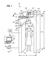
- FIG. 1 is a front, perspective, cut-away view of an exemplary trace detection portal 100 originally fitted (or retrofitted) with one or more components of an embodiment of a calibration apparatus 150 .
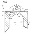
- FIG. 2 is an enlarged cross-sectional view of an upper portion of the trace detection portal 100 further illustrating the calibration apparatus 150 of FIG. 1 .
- an embodiment of the trace detection portal 100 has two vertical sidewalls 112 and 114 that are spaced apart from each other at a distance “W” to form a sample collection chamber 116 through which a person may pass.
- the sidewalls 112 and 114 each have a length “L” that is sufficient to bracket the width or depth of a person standing in the center of the sample collection chamber 116 .
- a ceiling 118 which is disposed at a height “H” above the floor or other surface that supports the trace detection portal 100 , also forms part of the sample collection chamber 116 .
- the height “H” of the ceiling 188 is sufficient to permit persons to pass easily into and through the sample collection chamber 116 .
- the upper and lower portions of the trace detection portal 100 are defined by a horizontal axis (e.g., a horizontal plane) 105 that passes through a center point 106 of the trace detection portal 100 .
- the upper portion of the trace detection portal 100 is at or above the axis 105 ; and the lower portion of the trace detection portal 100 is at or below the axis 105 .
- the upper portion of the sample collection chamber 116 gradually tapers from wide dimensions proximate the axis 105 to narrow dimensions proximate the sample collection port 120 .
- the sample collection port 120 is a hollow conduit extending from an interior upper surface of the sample collection chamber 116 into (and/or through) the ceiling 118 of the trace detection portal 100 .
- the sample collection port 120 collects and condenses the rising thermal plume of a person present within the sample collection chamber 116 .
- a movable trap 122 provided within the smaller cross-sectional dimensions of the sample collection port 120 collects particles comprising a substance of interest that are entrained in the rising thermal plume.
- articles comprising a substance of interest include particles, airborne trace chemicals in vapor form and skin flakes having adsorbed compounds thereon, among others.
- a fan 124 provided at the upper portion of the sample collection port 120 rotates at a speed required to draw air in at about the same flow rate as the rising thermal plume.
- the suction provided by the fan 124 directs the thermal plume through the trap 122 .
- a conveyor 126 provided on a substrate 102 moves the trap 122 into and out of a desorber 128 , which is also provided on the substrate 102 .
- the desorber 128 rapidly heats the inserted trap 122 to about 200 degrees Celsius to free the entrapped particles of interest.
- clean air injected into the desorber 128 is suctioned to draw the vaporized particles comprising a substance of interest into a detector 130 , which detects and identifies the particles comprising a substance of interest.
- a calibration apparatus 150 is coupled with substrate 102 , which has opposing first and second surfaces.
- a conveyor 126 and the desorber 128 may be disposed on the first surface of the substrate 102 , and the detector 130 may be supported on the second surface of the substrate 102 .
- a hollow conduit may link the desorber 128 to the detector 130 . Particles comprising a substance of interest may be aspirated from the desorber 128 , through the hollow conduit, and into the detector 130 for analysis.
- An embodiment of the calibration apparatus 150 may comprise a calibrant container 160 that releasably contains a substance the detector 130 is configured to uniquely recognize as a calibrant.
- the calibration apparatus 150 may further comprise an actuator 170 coupled with a calibrant container 160 and a control means 180 configured to operate the actuator 170 .
- the actuator 170 may include an air pump 196 , a first solenoid valve 185 , a second solenoid valve 180 , and/or conduits 181 , 182 , and 183 .
- the actuator 170 may be configured to discharge a predetermined amount of calibrant into the trace detection portal's sample collection chamber 116 in response to a signal generated by the control means 180 and relayed to the actuator 170 via a wired or wireless communications link 190 .
- a power source 195 provides electrical power to the control means 180 , the first solenoid valve 185 , the second solenoid valve 186 , the air pump 196 , the conveyor 126 , the desorber 128 , the detector 130 , and/or other components of the trace detection portal 100 .
- the power source 195 may be a generator, a battery, a photovoltaic cell, a hydrogen fuel cell, and the like.
- the conduit 181 connects the air pump 196 with the first solenoid valve 185 .
- the conduit 182 connects the first solenoid valve 185 with an inlet of a calibrant container 160 .
- the conduit 183 connects an outlet of a calibrant container 160 with the second solenoid valve 186 and with the sample collection chamber 116
- the conduit 184 connects the first solenoid valve 185 with the desorber 128 .
- Any suitable type of flexible or inflexible conduit may be used for each of conduit 181 , 182 , 183 , and 184 .
- suitable conduit materials include metal, metal alloys, glass, plastic, polymers, and the like.
- An end of the conduit 183 (or, alternatively, the outlet of the calibrant container) that connects with the sample collection chamber 116 may be suitably positioned at a predetermined distance from the trap 122 that permits the trap 122 to consistently collect all or a majority of the predetermined amount of calibrant that is released from the calibrant container 160 and infused into the sample collection chamber 116 .
- the exact placement of the conduit 183 (or the outlet of the calibrant container 160 ) will vary depending on a number of factors, including, but not limited to: the size of the sample collection chamber 116 , the configuration of the sample collection port 120 , whether the sample collection chamber 116 is fully or partially enclosed, and the like.
- the control means 180 is coupled with one or more components of the apparatus 150 described above.
- Non-limiting examples of the control means 180 include a computer subsystem 189 , a computer input means 188 , and a button, toggle, or slider switch 187 , among others.
- the computer subsystem 189 may comprise a data bus that links a computer processor with a memory, a transceiver or modem, and the computer input means 188 .
- the computer input means 188 may include, but is not limited to, a computer keyboard, a computer mouse, a computer touch screen, and the like.
- each of solenoid valves 185 , 186 occupies a first default closed position, which prevents hot air from the air pump 196 from entering the inlet of a calibrant container 160 and prevents calibrant from reaching the sample collection chamber 116 .
- Each of solenoid valves 185 , 186 moves to a second open position in response to a signal generated by the control means 180 .
- the solenoid valves 185 , 186 allow a predetermined amount of heated air and calibrant to infuse the sample collection chamber 116 .
- the calibrant is drawn upwards into the sample collection port 120 by the fan 124 .
- Particles comprising a substance of interest that forms the calibrant are captured and concentrated by the trap 122 .
- Conveyor 126 inserts the trap 122 into the desorber 128 , which rapidly heats the trap 122 to free the particles comprising the substance of interest.
- Clean air provided by the air pump 196 via conduit 181 and 184 is injected into the desorber 128 . The clean air and the particles of interest freed from the trap 122 are then aspirated into the detector 130 .
- the detector 130 is an ion mobility spectrometer (“IMS”), but other types of detectors known to a skilled artisan may also be used. (i.e., ion trap mobility spectrometer (“ITMS”), mass spectrometer, etc).
- IMS ion mobility spectrometer
- the particles comprising the substance of interest may be ionized (via a weak radioactive source or other means known to a skilled artisan) and caused to drift through a weak electric field.
- time of flight The time a particle takes to drift through the weak electric field is known as “time of flight.”
- time of flight is a distinct “fingerprint” that enables the detector 130 to uniquely identify many different kinds of substances of interest.
- the substance of interest may be a calibrant releasably contained within the calibrant container 160 .
- the calibrant may have a unique, predetermined “time of flight” different from the “times of flight” associated with other substances of interest, which may include, but are not limited to, explosives and narcotics, among others.
- a calibration signal may be output to one or more components of the trace detection portal 100 .
- the calibration signal may cause such components to automatically self-calibrate.
- One of these components may be an IMS detector 130 , which may automatically self-calibrate using one or more peak values from (current) IMS spectra data.
- FIG. 3 is a flowchart illustrating an embodiment of a method 300 (hereinafter, “the method 300 ”) of calibrating a trace detection portal 100 . It will be appreciated that the method steps shown in FIG. 3 and described herein may be performed in any suitable order, and that variants of the method 300 may include one or more steps in addition to the ones herein shown and described.
- the method 300 is initiated by transmitting a signal from the control means 180 to the calibration apparatus 160 (block 301 ). As previously described, the control means 180 may generate and transmit this signal.
- the method 300 further comprises releasing a predetermined amount of a substance contained in a calibrant container 160 into the sample collection chamber 116 (block 303 ). As noted above, this step may be accomplished by opening both solenoid valves 185 , 186 .
- the method 300 further comprises analyzing the measured amount of substance released into the sample collection chamber 116 (block 305 ). As previously noted, this step may be accomplished using the detector 130 and/or a trap 122 located in the sample collection port 120 .
- the method 300 yet further comprises identifying the measured amount of substance as a calibrant (block 307 ). As mentioned above, this step may be accomplished in an embodiment using ion mobility spectrometry (or other suitable detection method known to a skilled artisan), and/or by comparing the analysis data with the data on the above-referenced threat and/or calibrant lists.
- the method 300 further comprises automatically initiating a self-calibration of one or more components of the trace detection portal in response to the identification of the substance as a calibrant (block 309 ). As described above, this step may further include outputting a calibration signal to one or more components of the trace detection portal 100 . One such component may be the detector 130 .
- the method 300 further comprises generating a “clear” signal if the components of the trace detection portal 100 are each functioning properly (block 311 ). Alternatively, the method 300 further comprises generating a “fault” signal if one or more components of the trace detection portal 100 are malfunctioning (block 313 ). If the “clear” signal has been generated, the method 300 further comprises indicating via a display panel, or other communication means, that the trace detection portal 100 is ready to process persons (block 317 ). If the “fault” signal has been generated, the method 300 further comprises resetting and/or repairing the malfunctioning component(s) (block 315 ).
- the method 300 may loop back to the step of transmitting a signal to the calibration apparatus 150 (block 301 ) and proceed as described above.
- the method 300 may optionally comprise the step of setting a timekeeping device to transmit the signal to the calibration apparatus after the expiration of a predetermined period of time (block 319 ). After the timekeeping device is set, the method 300 may loop back to the step of transmitting the signal to the calibration apparatus (block 301 ). Alternatively, the method 300 may end after performing the steps represented by either (block 317 ) or (block 319 ).
- FIG. 4 is a cross-sectional diagram of an upper portion of the trace detection portal 100 illustrating another embodiment of a calibration apparatus 450 in which a calibrant container 460 containing a calibrant in an initial liquid, vapor, or aerosol state is insulated from receiving heat generated by the desorber 128 .
- the heating effects of the desorber 128 may be minimized or eliminated by locating the calibration apparatus 450 away from the desorber 128 , as illustratively shown in FIG. 4 .
- insulation may be provided by an insulator disposed between the calibration apparatus and the desorber 128 .
- the insulator may be air disposed between the calibrant container 460 and the substrate 102 and/or the desorber 128 .
- the insulator may be any suitable material having heat-insulative properties.
- suitable insulator materials include fiberglass, foam, ceramic fibers, microporous insulation, high temperature cloth, insulative laminates, insulative woven tapes, high temperature paper/felt (e.g., a blend of fibers, binders, and additives that can resist or contain heat), and the like.
- a calibrant container 460 may be formed of plastic or another material having heat-insulative properties.
- the calibration apparatus 450 also includes an actuator 470 .
- the actuator 470 is a plunger/piston that is directly coupled with an inlet of a calibrant container 460 .
- the actuator 470 may also be coupled with the control means 180 via wired or wireless communication link 190 , and optionally with the power source 195 .
- the actuator 470 operates to discharge a predetermined amount of calibrant into the sample collection chamber 116 for collection by the trap 122 and analysis by the detector 130 .
- control means 180 may be configured to initiate and execute a calibration of the trace detection portal upon receipt of a signal from a timekeeping device.
- the timekeeping device may be configured to automatically transmit the signal to the calibration apparatus upon expiration of a predetermined period-of-time.
- each of a calibrant containers 160 , 460 are formed of metal, plastic, or other suitable material, and are either single-use, disposable, or rechargeable.
- the phrase “single-use container” refers to a calibrant container 160 , 460 , the contents of which are designed to last the operational lifetime of the trace detection portal 100 in which it is used without replacement.
- the phrase “disposable container” refers to a calibrant container 160 , 460 designed to be thrown away after being emptied of its contents.
- the phrase “rechargeable container” refers to a calibrant container 160 , 460 designed to be refilled with a calibrant after being emptied of its contents.
- a single-use container may be fixedly attached to the substrate 102 .
- either a disposable container or a rechargeable container may be detachably coupled with the substrate 102 .
- FIG. 5 is another flowchart illustrating an embodiment of a method 500 (hereinafter, “the method 500 ”) of fitting or retrofitting to a trace detection portal 100 an embodiment of the claimed calibration apparatus 150 , 450 shown in FIGS. 1 , 2 , and 4 . It will be appreciated that the method steps shown in FIG. 5 and described herein may be performed in any suitable order, and that variants of the method 500 may include one or more steps in addition to the ones herein shown and described.
- a first step of the method 500 may be providing a calibrant container 160 , 460 (block 501 ).
- the method 500 may further comprise releasably storing a calibrant within the calibrant container 160 , 460 (block 503 ).
- the method 500 may further comprise configuring a trace detection portal 100 to detect and identify a calibrant and to automatically self-calibrate upon identification of the calibrant (block 505 ).
- the method 500 may further comprise detachably or fixedly coupling the calibrant container 160 , 460 with the sample collection chamber 116 of the trace detection portal 100 (block 507 ).
- the method 500 may further comprise insulating a calibrant container 160 , 460 from heat generated by a component of the trace detection portal 100 (block 509 ).
- the method 500 may further comprise thermally connecting a calibrant container 160 , 460 to absorb heat generated by a component of the trace detection portal 100 (block 511 ).
- the method 500 may end (block 515 ) or may optionally perform the steps represented by blocks 301 , 303 , 305 , 307 , 309 , 311 , 313 , 315 , 317 , and 319 of method 300 , as shown in FIG. 3 and described above.
- FIG. 6 is a diagram illustrating a quick-release bracket 670 that may be used to detachably couple a calibrant container 660 with a substrate 102 of a trace detection portal.
- the bracket 670 may be integrally formed as part of the substrate 102 or formed separately from the substrate 102 and attached thereto using a fastener.
- the bracket 670 may be attached to the substrate 102 using a fastener.
- fasteners include: clips, screws, bolts, nails, adhesives, and the like.
- the bracket 670 is illustratively depicted as a quick-release bracket that has a “c” shape with opposing ends 672 , 674 separated by a gap.
- the quick-release bracket 670 and a calibrant container 660 may take any suitable shape and/or configuration, and are not limited to those illustratively depicted in FIG. 6 .
- the bracket 670 may comprise a first strip of hook-and-loop material adhered to the substrate 102 and a second opposing strip of hook-and-loop material adhered to an exterior portion of a calibrant container 660 .
- the bracket 670 may comprise a half-cylinder or a four-sided box attached to the substrate 102 , and into which a calibrant container 660 removably fits. It will be appreciated, however, that other variants of the bracket 670 and a calibrant container 660 are possible.
- a calibrant container 660 having a generally cylindrical shape with an inlet 662 and an outlet 664 formed at opposing ends thereof is gripped by the bracket 670 .
- a calibrant container 660 may be inserted within the bracket 670 by positioning a calibrant container 660 adjacent the gap between the opposing ends 672 , 674 of the bracket 670 and compressing a calibrant container 660 until the opposing ends 672 , 674 spread apart and allow a calibrant container 660 to enter the interior of the bracket 670 .
- a calibrant container 660 may be detached from the bracket 670 by pulling a calibrant container 670 towards the gap between the opposing ends 672 , 674 of the bracket 670 until the opposing ends 672 , 674 spread apart and allow a calibrant container 660 to exit the bracket 670 .
- Embodiments of the invention illustrated in the appended drawings and illustratively described above position a detector 130 , a sample collection port 120 coupled with the detector, and a calibration apparatus 150 in an upper portion of a trace detection portal 100 .
- the upper portion of a trace detection portal includes regions of the trace detection portal that are at or above a horizontal plane (e.g., a plane that substantially parallels the floor or support surface on which the trace detection portal is placed) that passes through a center point of the trace detection portal.
- a horizontal plane e.g., a plane that substantially parallels the floor or support surface on which the trace detection portal is placed
- Alternative embodiments of the invention position the detector 130 (and/or a sample collection port 120 coupled with the detector 130 ) and/or the calibration apparatus 150 in a lower portion of the trace detection portal 100 .
- the lower portion of the trace detection portal 100 includes regions that are at or below the horizontal plane that passes through the center point of the trace detection portal.
- the detector 130 , a sample collection port 120 coupled with the detector 130 , and/or the calibration apparatus 150 may each be located in the floor or lower sidewalls of the trace detection portal 100 .
Landscapes
- Chemical & Material Sciences (AREA)
- Analytical Chemistry (AREA)
- Health & Medical Sciences (AREA)
- Life Sciences & Earth Sciences (AREA)
- Engineering & Computer Science (AREA)
- Biomedical Technology (AREA)
- Molecular Biology (AREA)
- Physics & Mathematics (AREA)
- Biochemistry (AREA)
- General Health & Medical Sciences (AREA)
- General Physics & Mathematics (AREA)
- Immunology (AREA)
- Pathology (AREA)
- Sampling And Sample Adjustment (AREA)
Abstract
Description
- 1. Field of the Invention
- The field of the invention relates to threat detection systems generally and, more particularly, to an apparatus and method for calibrating a trace detection portal.
- 2. Description of Related Art
- Extant threat detection systems check persons and objects for traces of substances of interest, such as narcotics and explosives. Such systems operate on the basis that trace amounts of substances of interest tend to be transferred to the body of a person who handles them, and from the person's body to any article the person's body may touch. Attempts have been made to test persons without physically touching them, but articles such as suitcases and handbags are tested by swiping them with a small piece of material that is then inserted into a known type of threat detection apparatus, which tests for the presence of the substance(s) of interest.
- A trace detection portal is a known type of threat detection system into and/or through which a person can walk. U.S. Pat. No. 6,073,499 (the “'499 patent”) illustrates a known type of trace detection portal. A trace detection portal, such as the one described in the '499 patent, operates based on the principle that a person's body heats the boundary of air surrounding it, and that the heated air, being less dense than ambient air further away from the body, flows upwardly to create a thermal plume about the body. The rising thermal plume entrains particles comprising a substance of interest present on the person's body and carries them up and away from the body. A fan or other airflow generator positioned in a portion of the trace detection portal above the person operates at a speed that approximates the airflow rate of the rising thermal plume. The fan thus directs the thermal plume to a detector without drawing significant volumes of ambient air into the detector. Consequently, a significant concentration of particles comprising the substance of interest is created.
- Some types of trace detection portals route the thermal plume directly to a detector for analysis. Other types first route the thermal plume through a trap that collects particles of interest from the thermal plume. The trap is then inserted within a desorber. Within the desorber, the trap is heated rapidly to temperatures of about 200 degrees Celsius to desorb and volatize the trapped particles comprising the substance of interest collected from the thermal plume. Clean air is injected into the desorber at a low rate and suction is applied to draw the clean air and the particles on the trap into the detector. The detector then detects and identifies the presence of the particles comprising the substance of interest. The trap will remain in the desorber until it is time for the next sample collection. The trap is then removed from the desorber, and repositioned across the airflow inlet at the upper portion of the sample collection chamber and rapidly cooled in preparation for the next sample collection. U.S. Patent Application Publication No.: 2004/0131503 illustrates such a known type of desorber and trap.
- Calibrating a trace detection portal to accurately and consistently test for particles comprising a substance of interest is difficult, and typically involves misting differing amounts of a calibrant into the trace detection portal's sample collection chamber by hand. For example, calibrant can be delivered into the portal detection chamber using a hand-held container such as a pistol-grip sprayer, aerosol spray can, nasal spay bottle, etc. Delivering an effluence of calibrant into the portal detection chamber in this manner is imprecise for several reasons. First, the amounts of calibrant released will differ from person to person depending on how long each person actuates the hand-held container. Second, if the calibrant is released too far from the upper portion of the detection chamber, ambient airflow turbulence will reduce the concentration too much for calibration purposes. Other challenges include ensuring a trace detection portal is calibrated on a routine basis, for example, at the beginning of each shift, which may be once every eight hours of usage that the trace detection portal is used. Non-calibration can create regular periods during which the portal cannot be used. Such periods decrease the trace detection portal's throughput.
- Long-felt needs thus exist for: an apparatus and method that can calibrate a trace detection portal automatically, simply, and accurately; an automatic and accurate calibration apparatus that can be easily retrofitted to existing trace portal detection systems; and a calibration apparatus and method for consistently dispersing a predetermined amount of calibrant into a sample collection chamber at a predetermined distance from a calibrant collection area of the trace detection portal.
- Embodiments of the invention disclosed herein overcome the disadvantages associated with the related art and meet the needs discussed above by providing novel, industrially applicable, and non-obvious apparatus and methods for automatically, simply, and accurately calibrating a trace detection portal. Embodiments of the apparatus include a calibrant container; a substance (or substances) uniquely identifiable by a trace detection portal as a calibrant; unique placement of the calibrant container's outlet relative to a substance collection port of a sample collection chamber; and/or computer executable instructions that, when executed by a computer processor, cause a consistent, repeatable release of a predetermined amount of calibrant into the sample collection chamber upon command and/or at pre-determined time intervals.
- Newly manufactured or retrofitted trace detection portals comprising an embodiment of the claimed calibration apparatus and/or using an embodiment of the claimed calibration method may be installed in airports, courthouses, schools, military installations, and any other government, commercial, industrial, or private venue where it is desired to detect threats posed by various types of explosives and/or other substances.
- A technical effect afforded by an embodiment of the invention is the output from a component of the trace detection portal of a signal that causes calibrant to be expelled from the calibrant container and into a trace detection portal's sample collection chamber. Another technical effect afforded by an embodiment of the invention is the output from a component of the trace detection portal of a signal that causes the trace detection portal's detector to perform a calibration routine upon detecting and uniquely identifying a substance of interest as a calibrant. Yet another technical effect afforded by an embodiment of the invention is the output from a component of the trace detection portal of a signal that causes a display panel and/or other communication means to indicate the trace detection portal is ready to process a person.
- Broadly, an embodiment of the invention includes an apparatus for calibrating a trace detection portal. The apparatus may include a calibrant container having an outlet configured to couple with a sample collection chamber of the trace detection portal. Additional components that may be included in the apparatus described above include means for releasably containing a calibrant, and means for coupling the means for releasably containing a calibrant with a sample collection chamber of the trace detection portal. Means for initiating a release of a predetermined amount of the calibrant into the sample collection chamber, and means for automatically self-calibrating one or more of its components upon detecting and uniquely identifying the calibrant may also be components of the above-described apparatus for calibrating a trace detection portal.
- Broadly, another embodiment of the invention provides a method for calibrating a trace detection portal. The method may include the step of providing a calibrant container having an outlet, and the step of releasably storing a calibrant within the calibrant container. The calibrant is a substance the trace detection portal is configured to detect and uniquely identify, and which (upon detection and identification by the trace detection portal) causes one or more components of the trace detection portal to automatically self-calibrate. Self-calibration of a trace detection portal component may include automatically performing one or more steps designed to improve and/or restore the component's operation and/or sensing accuracy.
- Additional method steps that may be included as part of the method described above, include the step of receiving a signal from a control means coupled with the trace detection portal; and the step of releasing a predetermined amount of a substance from a calibrant container into the sample collection chamber in response to the signal received from the control means. Other steps may include detecting, analyzing, and identifying the substance. Yet another step may include automatically initiating a self-calibration of one or more components of the trace detection portal upon identifying the substance as a calibrant.
- The above and other aspects of the various embodiments of the claimed invention will become more apparent when the following detailed description is considered together with the accompanying drawings in which:
-
FIG. 1 is a front, perspective, cut-away view of a trace detection portal fitted or retrofitted to include an embodiment of a calibration apparatus; -
FIG. 2 is an enlarged, cross-sectional view of an upper portion of the trace detection portal ofFIG. 1 more clearly depicting an embodiment of the calibration apparatus; -
FIG. 3 is a flowchart illustrating an embodiment of a method of operating an embodiment of the calibration apparatus; -
FIG. 4 is another cross-sectional view of the upper portion of the trace detection portal ofFIG. 1 more clearly depicting another embodiment of the calibration apparatus; -
FIG. 5 is another flowchart illustrating an embodiment of a method of fitting or retrofitting an embodiment of the calibration apparatus to a newly manufactured or existing trace detection portal; and -
FIG. 6 is a perspective view of an embodiment of a calibrant container and an embodiment of a bracket used to detachably or fixedly couple the calibrant container to a component of the trace detection portal ofFIG. 1 . - Reference is made herein to the accompanying drawings briefly described above, which show by way of illustration various embodiments of the claimed invention. Persons of ordinary skill in the above-referenced technological field will recognize that other embodiments may be utilized, and that structural, electrical, and procedural changes may be made without departing from the scope of the claimed invention. As used throughout all of the specification, figures, and claims, the singular (illustratively, “substance”) includes the plural (illustratively, “substances”), and the plural includes the singular.
-
FIG. 1 is a front, perspective, cut-away view of an exemplarytrace detection portal 100 originally fitted (or retrofitted) with one or more components of an embodiment of acalibration apparatus 150.FIG. 2 is an enlarged cross-sectional view of an upper portion of thetrace detection portal 100 further illustrating thecalibration apparatus 150 ofFIG. 1 . - Referring to
FIGS. 1 and 2 , an embodiment of thetrace detection portal 100 has twovertical sidewalls sample collection chamber 116 through which a person may pass. Thesidewalls sample collection chamber 116. Aceiling 118, which is disposed at a height “H” above the floor or other surface that supports thetrace detection portal 100, also forms part of thesample collection chamber 116. The height “H” of theceiling 188 is sufficient to permit persons to pass easily into and through thesample collection chamber 116. - Additionally, the upper and lower portions of the
trace detection portal 100 are defined by a horizontal axis (e.g., a horizontal plane) 105 that passes through acenter point 106 of thetrace detection portal 100. In an embodiment, the upper portion of thetrace detection portal 100 is at or above theaxis 105; and the lower portion of thetrace detection portal 100 is at or below theaxis 105. The upper portion of thesample collection chamber 116 gradually tapers from wide dimensions proximate theaxis 105 to narrow dimensions proximate thesample collection port 120. In an embodiment, thesample collection port 120 is a hollow conduit extending from an interior upper surface of thesample collection chamber 116 into (and/or through) theceiling 118 of thetrace detection portal 100. - The
sample collection port 120 collects and condenses the rising thermal plume of a person present within thesample collection chamber 116. Amovable trap 122 provided within the smaller cross-sectional dimensions of thesample collection port 120 collects particles comprising a substance of interest that are entrained in the rising thermal plume. Non-limiting examples of articles comprising a substance of interest include particles, airborne trace chemicals in vapor form and skin flakes having adsorbed compounds thereon, among others. - A
fan 124 provided at the upper portion of thesample collection port 120 rotates at a speed required to draw air in at about the same flow rate as the rising thermal plume. The suction provided by thefan 124 directs the thermal plume through thetrap 122. Aconveyor 126 provided on asubstrate 102 moves thetrap 122 into and out of adesorber 128, which is also provided on thesubstrate 102. Thedesorber 128 rapidly heats the insertedtrap 122 to about 200 degrees Celsius to free the entrapped particles of interest. Contemporaneously, clean air injected into thedesorber 128 is suctioned to draw the vaporized particles comprising a substance of interest into adetector 130, which detects and identifies the particles comprising a substance of interest. - In the embodiment shown in
FIGS. 1 and 2 , acalibration apparatus 150 is coupled withsubstrate 102, which has opposing first and second surfaces. Aconveyor 126 and thedesorber 128 may be disposed on the first surface of thesubstrate 102, and thedetector 130 may be supported on the second surface of thesubstrate 102. A hollow conduit may link thedesorber 128 to thedetector 130. Particles comprising a substance of interest may be aspirated from thedesorber 128, through the hollow conduit, and into thedetector 130 for analysis. - An embodiment of the
calibration apparatus 150 may comprise acalibrant container 160 that releasably contains a substance thedetector 130 is configured to uniquely recognize as a calibrant. Thecalibration apparatus 150 may further comprise anactuator 170 coupled with acalibrant container 160 and a control means 180 configured to operate theactuator 170. In an embodiment, theactuator 170 may include anair pump 196, afirst solenoid valve 185, asecond solenoid valve 180, and/orconduits actuator 170 may be configured to discharge a predetermined amount of calibrant into the trace detection portal'ssample collection chamber 116 in response to a signal generated by the control means 180 and relayed to theactuator 170 via a wired or wireless communications link 190. Apower source 195 provides electrical power to the control means 180, thefirst solenoid valve 185, thesecond solenoid valve 186, theair pump 196, theconveyor 126, thedesorber 128, thedetector 130, and/or other components of thetrace detection portal 100. Thepower source 195 may be a generator, a battery, a photovoltaic cell, a hydrogen fuel cell, and the like. - In an embodiment, the
conduit 181 connects theair pump 196 with thefirst solenoid valve 185. Additionally, theconduit 182 connects thefirst solenoid valve 185 with an inlet of acalibrant container 160. Theconduit 183 connects an outlet of acalibrant container 160 with thesecond solenoid valve 186 and with thesample collection chamber 116, and theconduit 184 connects thefirst solenoid valve 185 with thedesorber 128. Any suitable type of flexible or inflexible conduit may be used for each ofconduit - An end of the conduit 183 (or, alternatively, the outlet of the calibrant container) that connects with the
sample collection chamber 116 may be suitably positioned at a predetermined distance from thetrap 122 that permits thetrap 122 to consistently collect all or a majority of the predetermined amount of calibrant that is released from thecalibrant container 160 and infused into thesample collection chamber 116. The exact placement of the conduit 183 (or the outlet of the calibrant container 160) will vary depending on a number of factors, including, but not limited to: the size of thesample collection chamber 116, the configuration of thesample collection port 120, whether thesample collection chamber 116 is fully or partially enclosed, and the like. - The control means 180 is coupled with one or more components of the
apparatus 150 described above. Non-limiting examples of the control means 180 include acomputer subsystem 189, a computer input means 188, and a button, toggle, orslider switch 187, among others. Thecomputer subsystem 189 may comprise a data bus that links a computer processor with a memory, a transceiver or modem, and the computer input means 188. The computer input means 188 may include, but is not limited to, a computer keyboard, a computer mouse, a computer touch screen, and the like. - In the embodiment illustratively shown in
FIGS. 1 and 2 , each ofsolenoid valves air pump 196 from entering the inlet of acalibrant container 160 and prevents calibrant from reaching thesample collection chamber 116. Each ofsolenoid valves - When opened, the
solenoid valves sample collection chamber 116. Inside thesample collection chamber 116, at least the calibrant is drawn upwards into thesample collection port 120 by thefan 124. Particles comprising a substance of interest that forms the calibrant are captured and concentrated by thetrap 122.Conveyor 126 inserts thetrap 122 into thedesorber 128, which rapidly heats thetrap 122 to free the particles comprising the substance of interest. Clean air provided by theair pump 196 viaconduit desorber 128. The clean air and the particles of interest freed from thetrap 122 are then aspirated into thedetector 130. - In an embodiment, the
detector 130 is an ion mobility spectrometer (“IMS”), but other types of detectors known to a skilled artisan may also be used. (i.e., ion trap mobility spectrometer (“ITMS”), mass spectrometer, etc). Within anIMS detector 130, the particles comprising the substance of interest may be ionized (via a weak radioactive source or other means known to a skilled artisan) and caused to drift through a weak electric field. The time a particle takes to drift through the weak electric field is known as “time of flight.” Experiments have shown that particle time of flight is a distinct “fingerprint” that enables thedetector 130 to uniquely identify many different kinds of substances of interest. - In an embodiment, the substance of interest may be a calibrant releasably contained within the
calibrant container 160. The calibrant may have a unique, predetermined “time of flight” different from the “times of flight” associated with other substances of interest, which may include, but are not limited to, explosives and narcotics, among others. In an embodiment, when anIMS detector 130 detects the “time of flight” uniquely associated with the calibrant, a calibration signal may be output to one or more components of thetrace detection portal 100. The calibration signal may cause such components to automatically self-calibrate. One of these components may be anIMS detector 130, which may automatically self-calibrate using one or more peak values from (current) IMS spectra data. -
FIG. 3 is a flowchart illustrating an embodiment of a method 300 (hereinafter, “themethod 300”) of calibrating atrace detection portal 100. It will be appreciated that the method steps shown inFIG. 3 and described herein may be performed in any suitable order, and that variants of themethod 300 may include one or more steps in addition to the ones herein shown and described. - Referring to
FIGS. 1 , 2, and 3, themethod 300 is initiated by transmitting a signal from the control means 180 to the calibration apparatus 160 (block 301). As previously described, the control means 180 may generate and transmit this signal. Themethod 300 further comprises releasing a predetermined amount of a substance contained in acalibrant container 160 into the sample collection chamber 116 (block 303). As noted above, this step may be accomplished by opening bothsolenoid valves method 300 further comprises analyzing the measured amount of substance released into the sample collection chamber 116 (block 305). As previously noted, this step may be accomplished using thedetector 130 and/or atrap 122 located in thesample collection port 120. Themethod 300 yet further comprises identifying the measured amount of substance as a calibrant (block 307). As mentioned above, this step may be accomplished in an embodiment using ion mobility spectrometry (or other suitable detection method known to a skilled artisan), and/or by comparing the analysis data with the data on the above-referenced threat and/or calibrant lists. Themethod 300 further comprises automatically initiating a self-calibration of one or more components of the trace detection portal in response to the identification of the substance as a calibrant (block 309). As described above, this step may further include outputting a calibration signal to one or more components of thetrace detection portal 100. One such component may be thedetector 130. - The
method 300 further comprises generating a “clear” signal if the components of thetrace detection portal 100 are each functioning properly (block 311). Alternatively, themethod 300 further comprises generating a “fault” signal if one or more components of thetrace detection portal 100 are malfunctioning (block 313). If the “clear” signal has been generated, themethod 300 further comprises indicating via a display panel, or other communication means, that thetrace detection portal 100 is ready to process persons (block 317). If the “fault” signal has been generated, themethod 300 further comprises resetting and/or repairing the malfunctioning component(s) (block 315). Following the reset and/or repair, themethod 300 may loop back to the step of transmitting a signal to the calibration apparatus 150 (block 301) and proceed as described above. If thetrace detection portal 100 has been indicated to be ready to process a person, themethod 300 may optionally comprise the step of setting a timekeeping device to transmit the signal to the calibration apparatus after the expiration of a predetermined period of time (block 319). After the timekeeping device is set, themethod 300 may loop back to the step of transmitting the signal to the calibration apparatus (block 301). Alternatively, themethod 300 may end after performing the steps represented by either (block 317) or (block 319). -
FIG. 4 is a cross-sectional diagram of an upper portion of thetrace detection portal 100 illustrating another embodiment of acalibration apparatus 450 in which acalibrant container 460 containing a calibrant in an initial liquid, vapor, or aerosol state is insulated from receiving heat generated by thedesorber 128. The heating effects of thedesorber 128 may be minimized or eliminated by locating thecalibration apparatus 450 away from thedesorber 128, as illustratively shown inFIG. 4 . - In an embodiment where the
calibration apparatus 450 is positioned near thedesorber 128, insulation may be provided by an insulator disposed between the calibration apparatus and thedesorber 128. The insulator may be air disposed between thecalibrant container 460 and thesubstrate 102 and/or thedesorber 128. Alternatively, the insulator may be any suitable material having heat-insulative properties. Non-limiting examples of suitable insulator materials include fiberglass, foam, ceramic fibers, microporous insulation, high temperature cloth, insulative laminates, insulative woven tapes, high temperature paper/felt (e.g., a blend of fibers, binders, and additives that can resist or contain heat), and the like. Additionally (or alternatively), acalibrant container 460 may be formed of plastic or another material having heat-insulative properties. - Referring to
FIGS. 1 , 2, and 4, thecalibration apparatus 450 also includes anactuator 470. In an embodiment, theactuator 470 is a plunger/piston that is directly coupled with an inlet of acalibrant container 460. Theactuator 470 may also be coupled with the control means 180 via wired orwireless communication link 190, and optionally with thepower source 195. In response to a signal received from the control means 180, theactuator 470 operates to discharge a predetermined amount of calibrant into thesample collection chamber 116 for collection by thetrap 122 and analysis by thedetector 130. - In an embodiment, the control means 180 may be configured to initiate and execute a calibration of the trace detection portal upon receipt of a signal from a timekeeping device. The timekeeping device may be configured to automatically transmit the signal to the calibration apparatus upon expiration of a predetermined period-of-time.
- Referring to
FIGS. 1 , 2, and 4, each of acalibrant containers calibrant container trace detection portal 100 in which it is used without replacement. The phrase “disposable container” refers to acalibrant container calibrant container substrate 102. In another embodiment, either a disposable container or a rechargeable container may be detachably coupled with thesubstrate 102. -
FIG. 5 is another flowchart illustrating an embodiment of a method 500 (hereinafter, “themethod 500”) of fitting or retrofitting to atrace detection portal 100 an embodiment of the claimedcalibration apparatus FIGS. 1 , 2, and 4. It will be appreciated that the method steps shown inFIG. 5 and described herein may be performed in any suitable order, and that variants of themethod 500 may include one or more steps in addition to the ones herein shown and described. - Referring to
FIGS. 1 , 2, 4, and 5, a first step of themethod 500 may be providing acalibrant container 160,460 (block 501). Themethod 500 may further comprise releasably storing a calibrant within thecalibrant container 160,460 (block 503). Themethod 500 may further comprise configuring atrace detection portal 100 to detect and identify a calibrant and to automatically self-calibrate upon identification of the calibrant (block 505). Themethod 500 may further comprise detachably or fixedly coupling thecalibrant container sample collection chamber 116 of the trace detection portal 100 (block 507). Themethod 500 may further comprise insulating acalibrant container method 500 may further comprise thermally connecting acalibrant container block 509 or byblock 511, themethod 500 may end (block 515) or may optionally perform the steps represented byblocks method 300, as shown inFIG. 3 and described above. -
FIG. 6 is a diagram illustrating a quick-release bracket 670 that may be used to detachably couple acalibrant container 660 with asubstrate 102 of a trace detection portal. Referring toFIGS. 1 , 2, 4, and 6, during manufacture of a newtrace detection portal 100, for example, thebracket 670 may be integrally formed as part of thesubstrate 102 or formed separately from thesubstrate 102 and attached thereto using a fastener. Similarly, in an embodiment of the invention directed to retrofitting a previously manufacturedtrace detection portal 100, thebracket 670 may be attached to thesubstrate 102 using a fastener. Non-limiting examples of fasteners include: clips, screws, bolts, nails, adhesives, and the like. - In
FIG. 6 , thebracket 670 is illustratively depicted as a quick-release bracket that has a “c” shape with opposingends release bracket 670 and acalibrant container 660 may take any suitable shape and/or configuration, and are not limited to those illustratively depicted inFIG. 6 . For example, thebracket 670 may comprise a first strip of hook-and-loop material adhered to thesubstrate 102 and a second opposing strip of hook-and-loop material adhered to an exterior portion of acalibrant container 660. In another embodiment, thebracket 670 may comprise a half-cylinder or a four-sided box attached to thesubstrate 102, and into which acalibrant container 660 removably fits. It will be appreciated, however, that other variants of thebracket 670 and acalibrant container 660 are possible. - As shown in
FIG. 6 , an embodiment of acalibrant container 660 having a generally cylindrical shape with an inlet 662 and anoutlet 664 formed at opposing ends thereof is gripped by thebracket 670. Acalibrant container 660 may be inserted within thebracket 670 by positioning acalibrant container 660 adjacent the gap between the opposing ends 672,674 of thebracket 670 and compressing acalibrant container 660 until the opposing ends 672,674 spread apart and allow acalibrant container 660 to enter the interior of thebracket 670. Acalibrant container 660 may be detached from thebracket 670 by pulling acalibrant container 670 towards the gap between the opposing ends 672,674 of thebracket 670 until the opposing ends 672,674 spread apart and allow acalibrant container 660 to exit thebracket 670. - Embodiments of the invention illustrated in the appended drawings and illustratively described above position a
detector 130, asample collection port 120 coupled with the detector, and acalibration apparatus 150 in an upper portion of atrace detection portal 100. In an embodiment, the upper portion of a trace detection portal includes regions of the trace detection portal that are at or above a horizontal plane (e.g., a plane that substantially parallels the floor or support surface on which the trace detection portal is placed) that passes through a center point of the trace detection portal. Alternative embodiments of the invention, however, position the detector 130 (and/or asample collection port 120 coupled with the detector 130) and/or thecalibration apparatus 150 in a lower portion of thetrace detection portal 100. In an embodiment, the lower portion of thetrace detection portal 100 includes regions that are at or below the horizontal plane that passes through the center point of the trace detection portal. In such alternative embodiments, for example, thedetector 130, asample collection port 120 coupled with thedetector 130, and/or thecalibration apparatus 150 may each be located in the floor or lower sidewalls of thetrace detection portal 100. - A detailed description of various embodiments of the invention has been provided; however, modifications within the scope of the invention will be apparent to persons having ordinary skill in the above-referenced technological field. Such persons will appreciate that features described with respect to one embodiment may be applied to other embodiments. Thus, the scope of the invention is to be properly construed with reference to the following claims.
Claims (31)
Priority Applications (1)
| Application Number | Priority Date | Filing Date | Title |
|---|---|---|---|
| US11/554,160 US7594422B2 (en) | 2006-10-30 | 2006-10-30 | Apparatus and method for calibrating a trace detection portal |
Applications Claiming Priority (1)
| Application Number | Priority Date | Filing Date | Title |
|---|---|---|---|
| US11/554,160 US7594422B2 (en) | 2006-10-30 | 2006-10-30 | Apparatus and method for calibrating a trace detection portal |
Publications (2)
| Publication Number | Publication Date |
|---|---|
| US20080098794A1 true US20080098794A1 (en) | 2008-05-01 |
| US7594422B2 US7594422B2 (en) | 2009-09-29 |
Family
ID=39328534
Family Applications (1)
| Application Number | Title | Priority Date | Filing Date |
|---|---|---|---|
| US11/554,160 Expired - Fee Related US7594422B2 (en) | 2006-10-30 | 2006-10-30 | Apparatus and method for calibrating a trace detection portal |
Country Status (1)
| Country | Link |
|---|---|
| US (1) | US7594422B2 (en) |
Cited By (5)
| Publication number | Priority date | Publication date | Assignee | Title |
|---|---|---|---|---|
| WO2009155783A1 (en) * | 2008-06-27 | 2009-12-30 | 同方威视技术股份有限公司 | A portal detection apparatus for passer security |
| WO2010052604A1 (en) * | 2008-11-06 | 2010-05-14 | Brixs Limited | Security apparatus |
| GB2519853A (en) * | 2013-09-20 | 2015-05-06 | Micromass Ltd | Automated beam check |
| US11360065B2 (en) * | 2018-03-16 | 2022-06-14 | Teledyne Flir Detection, Inc. | Calibration systems and methods for analyte detectors |
| US11609214B2 (en) * | 2019-07-31 | 2023-03-21 | Rapiscan Systems, Inc. | Systems and methods for improving detection accuracy in electronic trace detectors |
Families Citing this family (17)
| Publication number | Priority date | Publication date | Assignee | Title |
|---|---|---|---|---|
| FR2953248B1 (en) * | 2009-12-02 | 2011-12-16 | Sagem Securite | DETECTION PORTAL |
| US9075028B2 (en) * | 2012-08-28 | 2015-07-07 | Raytheon Company | Airborne substance detector |
| EP3047503A1 (en) | 2013-09-20 | 2016-07-27 | Micromass UK Limited | Automated beam check |
| US9326838B1 (en) * | 2014-10-23 | 2016-05-03 | The North Umpqua Foundation | Fish DNA sampler |
| US9689857B1 (en) | 2016-03-08 | 2017-06-27 | Morpho Detection, Llc | Temperature influenced chemical vaporization and detection of compounds having low volatility |
| US9683981B1 (en) | 2016-03-08 | 2017-06-20 | Morpho Detection, Llc | Chemical vaporization and detection of compounds having low volatility |
| US10386340B2 (en) | 2016-03-31 | 2019-08-20 | Rapiscan Systems, Inc. | Detection of substances of interest using gas-solid phase chemistry |
| US10049868B2 (en) | 2016-12-06 | 2018-08-14 | Rapiscan Systems, Inc. | Apparatus for detecting constituents in a sample and method of using the same |
| US10707063B2 (en) | 2016-12-22 | 2020-07-07 | Rapiscan Systems, Inc. | Systems and methods for calibration, verification, and sensitivity checks for detectors |
| WO2018125441A1 (en) | 2016-12-28 | 2018-07-05 | Rapiscan Systems, Inc. | Ionization chamber having a potential-well for ion trapping and ion compression |
| US10458885B2 (en) | 2017-03-31 | 2019-10-29 | Rapiscan Systems, Inc. | Rapid desorber heating and cooling for trace detection |
| US11235329B2 (en) | 2017-08-10 | 2022-02-01 | Rapiscan Systems, Inc. | Systems and methods for substance detection using thermally stable collection devices |
| CN111630624A (en) | 2018-01-24 | 2020-09-04 | 拉皮斯坎系统股份有限公司 | Surface layer disruption and ionization using extreme ultraviolet radiation source |
| EP3588081B1 (en) * | 2018-06-22 | 2023-06-07 | Universität des Saarlandes | Device and method for calibrating a fluid detector with pre-concentrator |
| US11828749B2 (en) * | 2018-09-26 | 2023-11-28 | King Abdullah University Of Science And Technology | Airborne organic matter detection system and method |
| WO2021021166A1 (en) * | 2019-07-31 | 2021-02-04 | Rapiscan Systems, Inc. | Systems and methods for improving detection accuracy in electronic trace detectors |
| US11313771B1 (en) * | 2020-10-16 | 2022-04-26 | The Government of the United States of America, as renresenten by the Secretary of Homeland Securitv | Sample collection apparatus for scent detection |
Citations (44)
| Publication number | Priority date | Publication date | Assignee | Title |
|---|---|---|---|---|
| US3290920A (en) * | 1964-02-07 | 1966-12-13 | United States Steel Corp | Apparatus for calibrating vapor responsive detectors |
| US3791192A (en) * | 1972-07-03 | 1974-02-12 | Lockheed Aircraft Corp | Particle standard and calibration method |
| US4045997A (en) * | 1976-03-11 | 1977-09-06 | Marsland Engineering Limited | Air curtain device |
| US4202200A (en) * | 1976-07-01 | 1980-05-13 | Pye (Electronic Products) Limited | Apparatus for detecting explosive substances |
| US4331862A (en) * | 1979-02-23 | 1982-05-25 | Ryan Wayne L | Method for calibrating a particle counting machine and a calibration standard therefor |
| US4896547A (en) * | 1988-11-18 | 1990-01-30 | Thermedics Inc. | Air-sampling apparatus with easy walk-in access |
| US5493890A (en) * | 1994-03-16 | 1996-02-27 | Thermedics Detection Inc. | Apparatus and method for calibrating vapor/particle detection devices |
| US5502998A (en) * | 1994-04-25 | 1996-04-02 | The Procter And Gamble Company | Device and method for the simulation of samples of airborne substances |
| US5604295A (en) * | 1995-03-29 | 1997-02-18 | British-American Tobacco Company Limited | Calibrating particle emission-detecting instruments |
| US5753832A (en) * | 1994-11-03 | 1998-05-19 | Thermedics Detection Inc. | Vapor and particle sampling |
| US5762475A (en) * | 1996-03-18 | 1998-06-09 | Caterpillar Inc. | Automatic solenoid control valve calibration |
| US5915268A (en) * | 1997-12-22 | 1999-06-22 | Sandia Corporation | Vertical flow chemical detection portal |
| US5918254A (en) * | 1997-04-17 | 1999-06-29 | The United States Of America As Represented By The Secretary Of The Army | Low concentration aerosol generator |
| US6044688A (en) * | 1997-11-12 | 2000-04-04 | Fisher Controls International, Inc. | Device for ejecting a metered quantity of vaporized fluid |
| US6073476A (en) * | 1998-04-02 | 2000-06-13 | Lucent Technologies Inc. | Calibration sample for particle analyzers and method for making the same |
| US6073499A (en) * | 1998-03-12 | 2000-06-13 | Penn State Research Foundation | Chemical trace detection portal based on the natural airflow and heat transfer of the human body |
| US6334365B1 (en) * | 2000-12-11 | 2002-01-01 | Sandia Corporation | Target detection portal |
| US6408674B1 (en) * | 1999-04-07 | 2002-06-25 | Fisher Controls International | Pressure activated calibration system for chemical sensors |
| US20030029221A1 (en) * | 2001-01-23 | 2003-02-13 | Juneau Phillip J. | Device and method for introducing a known dust concentration spike for calibrating particulate matter continuous emission monitoring systems |
| US20030085348A1 (en) * | 2001-10-01 | 2003-05-08 | Lockheed Martin Corporation | Security system for NBC-safe building |
| US20030145644A1 (en) * | 2002-02-07 | 2003-08-07 | Walter Kidde Portable Equipment, Inc. | Self-calibrating carbon monoxide detector and method |
| US6627444B1 (en) * | 2000-08-07 | 2003-09-30 | Smiths Detection - Toronto Ltd. | Method and solid phase calibration sample for calibration of analytical instructions |
| US20030195396A1 (en) * | 1998-09-30 | 2003-10-16 | Scarantino Charles W. | Methods, systems, and associated implantable devices for dynamic monitoring of physiological and biological properties of tumors |
| US6642513B1 (en) * | 1998-10-06 | 2003-11-04 | General Electric Company | Materials and apparatus for the detection of contraband |
| US20030216660A1 (en) * | 1999-06-08 | 2003-11-20 | Ilan Ben-Oren | Breath test apparatus and methods |
| US6708572B2 (en) * | 2000-12-22 | 2004-03-23 | General Electric Company | Portal trace detection systems for detection of imbedded particles |
| US6790249B2 (en) * | 1999-09-02 | 2004-09-14 | Smiths Detection-Toronto Ltd. | Apparatus and method for screening people and articles to detect and/or decontaminate with respect to certain substances |
| US20050120778A1 (en) * | 2003-07-14 | 2005-06-09 | Brian Von Herzen | Distributed sensor array for fluid contaminant monitoring |
| US6918281B2 (en) * | 2000-05-11 | 2005-07-19 | Zellweger Analytics Limited | Gas sensor calibration system |
| US6969357B1 (en) * | 1999-06-08 | 2005-11-29 | Oridion Breathid Ltd. | Gas analyzer calibration checking device |
| US20050262924A1 (en) * | 2004-05-28 | 2005-12-01 | Honeywell International Inc. | Calibration device for gas sensors |
| US20060118416A1 (en) * | 2004-12-08 | 2006-06-08 | Honeywell International, Inc. | Electrochemical sensor system |
| US20060195749A1 (en) * | 2004-12-07 | 2006-08-31 | Cohen Stephen A | Calibration control for pin electronics |
| US7141786B2 (en) * | 2004-09-08 | 2006-11-28 | General Electric Company | Particle sampling preconcentrator |
| US20060266098A1 (en) * | 2005-05-24 | 2006-11-30 | Honeywell International Inc. | Hydrogen sulfide generator for sensor calibration |
| US7168287B2 (en) * | 2002-09-26 | 2007-01-30 | Inficon Gmbh | Reference leakage device for leak sniffer detector |
| US7180441B2 (en) * | 2004-04-14 | 2007-02-20 | Safeview, Inc. | Multi-sensor surveillance portal |
| US20070045128A1 (en) * | 2005-08-19 | 2007-03-01 | Honeywell International Inc. | Chlorine dioxide sensor |
| US20070076101A1 (en) * | 2005-09-30 | 2007-04-05 | Baer Richard L | Self-calibrating and/or self-testing camera module |
| US20070114386A1 (en) * | 2005-11-16 | 2007-05-24 | Steven Fischer | Reference mass introduction via a capillary |
| US7343782B2 (en) * | 2006-04-10 | 2008-03-18 | Northrop Grumman Corporation | System and method for performing quantifiable release spore testing on bioaerosol detection technologies |
| US7357043B2 (en) * | 2005-09-07 | 2008-04-15 | Nomadics, Inc. | Chemical trace detection portal based on the natural airflow and heat transfer of vehicles |
| US20080156071A1 (en) * | 2006-12-29 | 2008-07-03 | Peter Tobias | Gas sensor calibration from fluid |
| US20090036758A1 (en) * | 2003-12-09 | 2009-02-05 | Dexcom, Inc. | Signal processing for continuous analyte sensor |
Family Cites Families (1)
| Publication number | Priority date | Publication date | Assignee | Title |
|---|---|---|---|---|
| US7136605B2 (en) | 2002-12-24 | 2006-11-14 | Ricoh Company, Ltd. | Image forming apparatus, method of evaluating noise, and methods of manufacturing and modifying image forming apparatus |
-
2006
- 2006-10-30 US US11/554,160 patent/US7594422B2/en not_active Expired - Fee Related
Patent Citations (48)
| Publication number | Priority date | Publication date | Assignee | Title |
|---|---|---|---|---|
| US3290920A (en) * | 1964-02-07 | 1966-12-13 | United States Steel Corp | Apparatus for calibrating vapor responsive detectors |
| US3791192A (en) * | 1972-07-03 | 1974-02-12 | Lockheed Aircraft Corp | Particle standard and calibration method |
| US4045997A (en) * | 1976-03-11 | 1977-09-06 | Marsland Engineering Limited | Air curtain device |
| US4202200A (en) * | 1976-07-01 | 1980-05-13 | Pye (Electronic Products) Limited | Apparatus for detecting explosive substances |
| US4331862A (en) * | 1979-02-23 | 1982-05-25 | Ryan Wayne L | Method for calibrating a particle counting machine and a calibration standard therefor |
| US4896547A (en) * | 1988-11-18 | 1990-01-30 | Thermedics Inc. | Air-sampling apparatus with easy walk-in access |
| US5493890A (en) * | 1994-03-16 | 1996-02-27 | Thermedics Detection Inc. | Apparatus and method for calibrating vapor/particle detection devices |
| US5502998A (en) * | 1994-04-25 | 1996-04-02 | The Procter And Gamble Company | Device and method for the simulation of samples of airborne substances |
| US5753832A (en) * | 1994-11-03 | 1998-05-19 | Thermedics Detection Inc. | Vapor and particle sampling |
| US5604295A (en) * | 1995-03-29 | 1997-02-18 | British-American Tobacco Company Limited | Calibrating particle emission-detecting instruments |
| US5762475A (en) * | 1996-03-18 | 1998-06-09 | Caterpillar Inc. | Automatic solenoid control valve calibration |
| US5918254A (en) * | 1997-04-17 | 1999-06-29 | The United States Of America As Represented By The Secretary Of The Army | Low concentration aerosol generator |
| US6044688A (en) * | 1997-11-12 | 2000-04-04 | Fisher Controls International, Inc. | Device for ejecting a metered quantity of vaporized fluid |
| US5915268A (en) * | 1997-12-22 | 1999-06-22 | Sandia Corporation | Vertical flow chemical detection portal |
| US6073499A (en) * | 1998-03-12 | 2000-06-13 | Penn State Research Foundation | Chemical trace detection portal based on the natural airflow and heat transfer of the human body |
| US6073476A (en) * | 1998-04-02 | 2000-06-13 | Lucent Technologies Inc. | Calibration sample for particle analyzers and method for making the same |
| US20030195396A1 (en) * | 1998-09-30 | 2003-10-16 | Scarantino Charles W. | Methods, systems, and associated implantable devices for dynamic monitoring of physiological and biological properties of tumors |
| US6815670B2 (en) * | 1998-10-06 | 2004-11-09 | General Electric Company | Materials and apparatus for the detection of contraband |
| US6642513B1 (en) * | 1998-10-06 | 2003-11-04 | General Electric Company | Materials and apparatus for the detection of contraband |
| US6408674B1 (en) * | 1999-04-07 | 2002-06-25 | Fisher Controls International | Pressure activated calibration system for chemical sensors |
| US20030216660A1 (en) * | 1999-06-08 | 2003-11-20 | Ilan Ben-Oren | Breath test apparatus and methods |
| US6969357B1 (en) * | 1999-06-08 | 2005-11-29 | Oridion Breathid Ltd. | Gas analyzer calibration checking device |
| US6790249B2 (en) * | 1999-09-02 | 2004-09-14 | Smiths Detection-Toronto Ltd. | Apparatus and method for screening people and articles to detect and/or decontaminate with respect to certain substances |
| US6918281B2 (en) * | 2000-05-11 | 2005-07-19 | Zellweger Analytics Limited | Gas sensor calibration system |
| US6627444B1 (en) * | 2000-08-07 | 2003-09-30 | Smiths Detection - Toronto Ltd. | Method and solid phase calibration sample for calibration of analytical instructions |
| US6334365B1 (en) * | 2000-12-11 | 2002-01-01 | Sandia Corporation | Target detection portal |
| US6840122B1 (en) * | 2000-12-22 | 2005-01-11 | General Electric Company | Portal trace detection systems for detection of imbedded particles |
| US6708572B2 (en) * | 2000-12-22 | 2004-03-23 | General Electric Company | Portal trace detection systems for detection of imbedded particles |
| US20030029221A1 (en) * | 2001-01-23 | 2003-02-13 | Juneau Phillip J. | Device and method for introducing a known dust concentration spike for calibrating particulate matter continuous emission monitoring systems |
| US6694796B2 (en) * | 2001-01-23 | 2004-02-24 | B3 Systems, Inc. | Device and method for introducing a known dust concentration spike for calibrating particulate matter continuous emission monitoring systems |
| US20030085348A1 (en) * | 2001-10-01 | 2003-05-08 | Lockheed Martin Corporation | Security system for NBC-safe building |
| US20030145644A1 (en) * | 2002-02-07 | 2003-08-07 | Walter Kidde Portable Equipment, Inc. | Self-calibrating carbon monoxide detector and method |
| US7168287B2 (en) * | 2002-09-26 | 2007-01-30 | Inficon Gmbh | Reference leakage device for leak sniffer detector |
| US20050120778A1 (en) * | 2003-07-14 | 2005-06-09 | Brian Von Herzen | Distributed sensor array for fluid contaminant monitoring |
| US20090043542A1 (en) * | 2003-12-09 | 2009-02-12 | Dexcom, Inc. | Signal processing for continuous analyte sensor |
| US20090036758A1 (en) * | 2003-12-09 | 2009-02-05 | Dexcom, Inc. | Signal processing for continuous analyte sensor |
| US7180441B2 (en) * | 2004-04-14 | 2007-02-20 | Safeview, Inc. | Multi-sensor surveillance portal |
| US20050262924A1 (en) * | 2004-05-28 | 2005-12-01 | Honeywell International Inc. | Calibration device for gas sensors |
| US7141786B2 (en) * | 2004-09-08 | 2006-11-28 | General Electric Company | Particle sampling preconcentrator |
| US20060195749A1 (en) * | 2004-12-07 | 2006-08-31 | Cohen Stephen A | Calibration control for pin electronics |
| US20060118416A1 (en) * | 2004-12-08 | 2006-06-08 | Honeywell International, Inc. | Electrochemical sensor system |
| US20060266098A1 (en) * | 2005-05-24 | 2006-11-30 | Honeywell International Inc. | Hydrogen sulfide generator for sensor calibration |
| US20070045128A1 (en) * | 2005-08-19 | 2007-03-01 | Honeywell International Inc. | Chlorine dioxide sensor |
| US7357043B2 (en) * | 2005-09-07 | 2008-04-15 | Nomadics, Inc. | Chemical trace detection portal based on the natural airflow and heat transfer of vehicles |
| US20070076101A1 (en) * | 2005-09-30 | 2007-04-05 | Baer Richard L | Self-calibrating and/or self-testing camera module |
| US20070114386A1 (en) * | 2005-11-16 | 2007-05-24 | Steven Fischer | Reference mass introduction via a capillary |
| US7343782B2 (en) * | 2006-04-10 | 2008-03-18 | Northrop Grumman Corporation | System and method for performing quantifiable release spore testing on bioaerosol detection technologies |
| US20080156071A1 (en) * | 2006-12-29 | 2008-07-03 | Peter Tobias | Gas sensor calibration from fluid |
Cited By (8)
| Publication number | Priority date | Publication date | Assignee | Title |
|---|---|---|---|---|
| WO2009155783A1 (en) * | 2008-06-27 | 2009-12-30 | 同方威视技术股份有限公司 | A portal detection apparatus for passer security |
| US20090320620A1 (en) * | 2008-06-27 | 2009-12-31 | Nuctech Company Limited | Door-type passenger security inspection apparatus and method for detecting contraband articles such as narcotic drugs, explosives |
| CN102095612A (en) * | 2008-06-27 | 2011-06-15 | 同方威视技术股份有限公司 | Door-type pedestrian safety inspection device and method for detecting contraband goods of drug, explosive substance and the like |
| WO2010052604A1 (en) * | 2008-11-06 | 2010-05-14 | Brixs Limited | Security apparatus |
| GB2519853A (en) * | 2013-09-20 | 2015-05-06 | Micromass Ltd | Automated beam check |
| GB2519853B (en) * | 2013-09-20 | 2016-09-14 | Micromass Ltd | Automated beam check |
| US11360065B2 (en) * | 2018-03-16 | 2022-06-14 | Teledyne Flir Detection, Inc. | Calibration systems and methods for analyte detectors |
| US11609214B2 (en) * | 2019-07-31 | 2023-03-21 | Rapiscan Systems, Inc. | Systems and methods for improving detection accuracy in electronic trace detectors |
Also Published As
| Publication number | Publication date |
|---|---|
| US7594422B2 (en) | 2009-09-29 |
Similar Documents
| Publication | Publication Date | Title |
|---|---|---|
| US7594422B2 (en) | Apparatus and method for calibrating a trace detection portal | |
| EP1792161B1 (en) | Particle sampling preconcentrator | |
| US9696288B2 (en) | Attached matter testing device and testing method | |
| EP2450689B1 (en) | Sample collecting method and sample collecting apparatus | |
| US8952327B2 (en) | Detection system assembly, dryer cartridge and regenerator and methods for making and using the same | |
| US9354153B2 (en) | Hand-held trace particle sampling system and method of operating the same | |
| US20090044641A1 (en) | Trace sampler | |
| JP6270851B2 (en) | Sampling thermal desorption system | |
| EP1894004A2 (en) | Trace sampling | |
| JP2002503808A (en) | Handheld detection system using GC / IMS | |
| US20110259127A1 (en) | Sample Collector and Sample Collecting Device for an Analysis Device and Method for the Operation Thereof | |
| JPH09126966A (en) | Sampling room of explosive-substance detecting and screeningdevice | |
| CN103439150B (en) | A kind of footwear VOC volatilization sampling apparatus and method | |
| US7299709B1 (en) | Aerosol collecting device for a chemical detector | |
| US5493890A (en) | Apparatus and method for calibrating vapor/particle detection devices | |
| JP2010066243A (en) | Apparatus and method for inspecting material | |
| CN105531586A (en) | Method and portable ion mobility spectrometer for the detection of an aerosol | |
| US20110108727A9 (en) | Method and System for Analysing a Dose Formulation of a Metered Dose Device | |
| GB2088055A (en) | Apparatus for collection of sorbed substances | |
| GB2575420A (en) | Use of a Direction Signal in Controlling a Device for Detecting a Desorbed Sample | |
| Nissinen | Set up and calibration of an extractive electrosprayionization (EESI) inlet for measuring organic aerosolusing a time-of-flight mass spectrometer | |
| CA3121678C (en) | Mass spectrometry of surface contamination | |
| US20190267224A1 (en) | Interface device | |
| CN116917728A (en) | Dynamic heating of differential mobility spectrometer units | |
| Schwarz et al. | Sampling and analysis of exhaled breath particles |
Legal Events
| Date | Code | Title | Description |
|---|---|---|---|
| AS | Assignment |
Owner name: GENERAL ELECTRIC COMPANY, NEW YORK Free format text: ASSIGNMENT OF ASSIGNORS INTEREST;ASSIGNORS:PATTERSON, MICHAEL E.;PERRY, KEVIN J.;REEL/FRAME:018453/0130 Effective date: 20061030 |
|
| AS | Assignment |
Owner name: GE HOMELAND PROTECTION, INC., CALIFORNIA Free format text: ASSIGNMENT OF ASSIGNORS INTEREST;ASSIGNOR:GENERAL ELECTRIC COMPANY;REEL/FRAME:019304/0798 Effective date: 20070518 Owner name: GE HOMELAND PROTECTION, INC.,CALIFORNIA Free format text: ASSIGNMENT OF ASSIGNORS INTEREST;ASSIGNOR:GENERAL ELECTRIC COMPANY;REEL/FRAME:019304/0798 Effective date: 20070518 |
|
| STCF | Information on status: patent grant |
Free format text: PATENTED CASE |
|
| AS | Assignment |
Owner name: MORPHO DETECTION, INC., CALIFORNIA Free format text: CHANGE OF NAME;ASSIGNOR:GE HOMELAND PROTECTION, INC.;REEL/FRAME:024879/0227 Effective date: 20091001 |
|
| FEPP | Fee payment procedure |
Free format text: PAYOR NUMBER ASSIGNED (ORIGINAL EVENT CODE: ASPN); ENTITY STATUS OF PATENT OWNER: LARGE ENTITY |
|
| FPAY | Fee payment |
Year of fee payment: 4 |
|
| AS | Assignment |
Owner name: MORPHO DETECTION, LLC, CALIFORNIA Free format text: CHANGE OF NAME;ASSIGNOR:MORPHO DETECTION, INC.;REEL/FRAME:032122/0067 Effective date: 20131230 |
|
| AS | Assignment |
Owner name: MORPHO DETECTION, LLC, CALIFORNIA Free format text: CORRECTIVE ASSIGNMENT TO CORRECT THE THE PURPOSE OF THE CORRECTION IS TO ADD THE CERTIFICATE OF CONVERSION PAGE TO THE ORIGINALLY FILED CHANGE OF NAME DOCUMENT PREVIOUSLY RECORDED ON REEL 032122 FRAME 67. ASSIGNOR(S) HEREBY CONFIRMS THE THE CHANGE OF NAME;ASSIGNOR:MORPHO DETECTION, INC.;REEL/FRAME:032470/0682 Effective date: 20131230 |
|
| FPAY | Fee payment |
Year of fee payment: 8 |
|
| AS | Assignment |
Owner name: SMITHS DETECTION, LLC, CALIFORNIA Free format text: CERTIFICATE OF AMENDMENT: NAME CHANGE;ASSIGNOR:MORPHO DETECTION, LLC;REEL/FRAME:043749/0208 Effective date: 20170406 |
|
| AS | Assignment |
Owner name: MD US TRACE HOLDING, LLC, CALIFORNIA Free format text: ASSIGNMENT OF ASSIGNORS INTEREST;ASSIGNOR:SMITHS DETECTION, LLC;REEL/FRAME:044037/0192 Effective date: 20170707 |
|
| AS | Assignment |
Owner name: RAPISCAN SYSTEMS, INC., CALIFORNIA Free format text: MERGER;ASSIGNOR:MD US TRACE HOLDING, LLC;REEL/FRAME:044100/0521 Effective date: 20170707 |
|
| FEPP | Fee payment procedure |
Free format text: MAINTENANCE FEE REMINDER MAILED (ORIGINAL EVENT CODE: REM.); ENTITY STATUS OF PATENT OWNER: LARGE ENTITY |
|
| LAPS | Lapse for failure to pay maintenance fees |
Free format text: PATENT EXPIRED FOR FAILURE TO PAY MAINTENANCE FEES (ORIGINAL EVENT CODE: EXP.); ENTITY STATUS OF PATENT OWNER: LARGE ENTITY |
|
| STCH | Information on status: patent discontinuation |
Free format text: PATENT EXPIRED DUE TO NONPAYMENT OF MAINTENANCE FEES UNDER 37 CFR 1.362 |
|
| FP | Lapsed due to failure to pay maintenance fee |
Effective date: 20210929 |