US20090281663A1 - Device and method for mixing materials - Google Patents
Device and method for mixing materials Download PDFInfo
- Publication number
- US20090281663A1 US20090281663A1 US12/435,791 US43579109A US2009281663A1 US 20090281663 A1 US20090281663 A1 US 20090281663A1 US 43579109 A US43579109 A US 43579109A US 2009281663 A1 US2009281663 A1 US 2009281663A1
- Authority
- US
- United States
- Prior art keywords
- rotation
- main
- support
- rotatable support
- offset
- Prior art date
- Legal status (The legal status is an assumption and is not a legal conclusion. Google has not performed a legal analysis and makes no representation as to the accuracy of the status listed.)
- Abandoned
Links
Images


Classifications
-
- B—PERFORMING OPERATIONS; TRANSPORTING
- B29—WORKING OF PLASTICS; WORKING OF SUBSTANCES IN A PLASTIC STATE IN GENERAL
- B29B—PREPARATION OR PRETREATMENT OF THE MATERIAL TO BE SHAPED; MAKING GRANULES OR PREFORMS; RECOVERY OF PLASTICS OR OTHER CONSTITUENTS OF WASTE MATERIAL CONTAINING PLASTICS
- B29B7/00—Mixing; Kneading
- B29B7/02—Mixing; Kneading non-continuous, with mechanical mixing or kneading devices, i.e. batch type
- B29B7/06—Mixing; Kneading non-continuous, with mechanical mixing or kneading devices, i.e. batch type with movable mixing or kneading devices
- B29B7/10—Mixing; Kneading non-continuous, with mechanical mixing or kneading devices, i.e. batch type with movable mixing or kneading devices rotary
- B29B7/106—Mixing; Kneading non-continuous, with mechanical mixing or kneading devices, i.e. batch type with movable mixing or kneading devices rotary using rotary casings
-
- B—PERFORMING OPERATIONS; TRANSPORTING
- B01—PHYSICAL OR CHEMICAL PROCESSES OR APPARATUS IN GENERAL
- B01F—MIXING, e.g. DISSOLVING, EMULSIFYING OR DISPERSING
- B01F29/00—Mixers with rotating receptacles
- B01F29/10—Mixers with rotating receptacles with receptacles rotated about two different axes, e.g. receptacles having planetary motion
-
- B—PERFORMING OPERATIONS; TRANSPORTING
- B01—PHYSICAL OR CHEMICAL PROCESSES OR APPARATUS IN GENERAL
- B01F—MIXING, e.g. DISSOLVING, EMULSIFYING OR DISPERSING
- B01F31/00—Mixers with shaking, oscillating, or vibrating mechanisms
- B01F31/10—Mixers with shaking, oscillating, or vibrating mechanisms with a mixing receptacle rotating alternately in opposite directions
-
- B—PERFORMING OPERATIONS; TRANSPORTING
- B01—PHYSICAL OR CHEMICAL PROCESSES OR APPARATUS IN GENERAL
- B01F—MIXING, e.g. DISSOLVING, EMULSIFYING OR DISPERSING
- B01F35/00—Accessories for mixers; Auxiliary operations or auxiliary devices; Parts or details of general application
- B01F35/20—Measuring; Control or regulation
- B01F35/22—Control or regulation
- B01F35/221—Control or regulation of operational parameters, e.g. level of material in the mixer, temperature or pressure
- B01F35/2214—Speed during the operation
- B01F35/22142—Speed of the mixing device during the operation
- B01F35/221422—Speed of rotation of the mixing axis, stirrer or receptacle during the operation
-
- B—PERFORMING OPERATIONS; TRANSPORTING
- B01—PHYSICAL OR CHEMICAL PROCESSES OR APPARATUS IN GENERAL
- B01F—MIXING, e.g. DISSOLVING, EMULSIFYING OR DISPERSING
- B01F35/00—Accessories for mixers; Auxiliary operations or auxiliary devices; Parts or details of general application
- B01F35/20—Measuring; Control or regulation
- B01F35/22—Control or regulation
- B01F35/221—Control or regulation of operational parameters, e.g. level of material in the mixer, temperature or pressure
- B01F35/2215—Temperature
Definitions
- Dual-axis centrifuges have been used to mix high-viscosity materials. These devices induce strong internal shear forces on the materials being mixed, allowing for rapid mixing of materials.
- Dual-axis centrifuges include devices such as the SpeedMixerTM devices available from FlackTek of Landrum, S.C.
- a conventional dual-axis centrifuge includes a turntable positioned on and at an angle to a carousel. A cup of material to be mixed is placed on the turntable. When the centrifuge is activated, the turntable rotates around its axis and the carousel rotates around its axis in the opposite direction of the turntable. The resulting movement causes materials in the cup to be mixed relatively quickly and thoroughly.
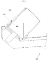
- FIG. 1 shows a device having a support that is rotatable independently of the attached turntables according to an embodiment of the present invention.
- FIG. 2 shows a cross-section of a cup containing a material in a configuration resulting from rotation of only a turntable in a device according to an embodiment of the present invention.
- FIG. 3 shows a cross-section of a cup containing a material in a configuration resulting from rotation of only a support in a device according to an embodiment of the present invention.
- FIG. 4 shows a cross-section of a cup containing a material in a configuration resulting from only simultaneous rotation of a support and an attached turntable.
- FIG. 5 shows a rotation procedure for use with a device according to an embodiment of the present invention.
- FIG. 6 shows a device with a user interface according to an embodiment of the invention.
- FIG. 7 shows a device having multiple turntables and materials cups according to an embodiment of the present invention.
- FIG. 8 shows a vision system that may be used with a mixing device and/or method according to an embodiment of the present invention.
- Devices may include a rotatable main support such as a carousel and one or more rotatable offset supports such as turntables arranged on or in the main support, where the main support and the offset support can be rotated both concurrently and independently of one another.
- Materials to be mixed may be placed in holders such as cups on the offset supports.
- the dead zone may cause a buildup of unmixed material.
- these effects may be less pronounced, though they may still increase the total time required to sufficiently mix the materials.
- a particulate material is mixed with a viscous or semi-solid material such as a polymer, the particulate material may collect in the dead zone. This buildup can prevent the materials from mixing completely, require the centrifuge to be run for an unacceptably long period of time to completely mix the materials, or require operator intervention to loosen the undesirable buildup during the mixing process.
- FIG. 1 shows a device according to an embodiment of the present invention.
- the device 100 includes a rotatable main support 120 and one or more offset supports taking the form in this embodiment of turntables 101 , 102 , 103 attached to the main support.
- Each turntable may rotate independently of the main support, and may rotate in an opposite direction from the main support or in the same direction as the main support.
- each offset support has an axis of rotation that is different from the axis of rotation of the main support.
- the turntables are arranged around the axis of rotation of the main support, so that they rotate around the axis of rotation of the main support when the main support is rotated.
- each turntable is arranged so that the axis of rotation of the turntable is at an angle with respect to the axis of rotation of the support.
- each turntable's axis of rotation can be tilted at an angle of about 30-60° relative to the support's axis of rotation.
- Holders in the form of cups 110 , 111 , 112 may be placed in or may be part of the turntables to contain material to be mixed.
- the cups may be pre-filled with the mixture materials before being placed on the turntables, or the cups may be filled while positioned on the turntables.
- the holders e.g., the cups 110 , 111 , 112
- the offset supports e.g., the turntables 101 , 102 , 103
- the cups may be interchangeable, such that any cup may be connected to any turntable.
- Each turntable 101 , 102 , 103 may be disposed at a distance from the rotational center of the support. Typically, when multiple turntables are used each is positioned the same distance from the rotational center of the support.
- three turntables may be disposed on arms 121 , 122 , 123 .
- the turntables may be arranged on the support so as to counterbalance each other.
- Counterweights also may be used to reduce undesirable vibration or other effects, such as for devices having a single turntable, or where varying amounts of material are placed in multiple cups.
- the turntables 101 , 102 , 103 may be rotated independently of the main support 120 .
- the main support 120 may be driven by a separate motor than the turntables 101 , 102 , 103 .
- the turntables 101 , 102 , 103 may be driven by a single motor or by separate motors.
- the turntables may be controlled together, so that each turntable is rotated at the same time and speed, or each turntable may be controlled independently.
- a processor or other device may control rotation of the main support and the turntables. By performing combinations of concurrent turntable and main support rotations, independent main support rotation, and/or independent turntable rotation, dead zones may be reduced or eliminated during mixing.
- FIG. 2 shows a cross-section of a cup 110 containing a material 200 in a configuration that may result from rotation of only the turntable 101 , while the main support is not rotating.
- the cup rotation typically will cause the material 200 to be pushed toward and up the inside surface of the cup wall.
- FIG. 3 shows a cross-section of a cup 110 containing a material 300 in a configuration that may result from rotation of only the main support 120 , while the turntable is not rotating.
- the cup rotation typically will cause the material 300 to be pushed toward the outer portion of the cup relative to the center of the main support.
- different portions of the material 200 , 300 in each cup may be subjected to various different forces.
- the material 200 may be moved away from the bottom center portion of the cup.
- the material 300 may be moved away from the inner surface of the cup on those portions closer to the center of the support.
- Other internal shear forces may be exerted on the material in each configuration.
- FIG. 4 shows a cross-section of a cup 110 containing a material 400 in a configuration that may result from concurrent rotation of both the support 120 and the turntable 101 .
- the combined motion typically will cause the material 400 to collect in the lower portion of the cup.
- Various currents and mixing regions may be created in the material, such as those shown by the dashed arrows.
- both the carousel and the turntables rotate simultaneously, which can leave a dead zone 401 where little or no mixing occurs in the bottom central portion of the material 400 .
- devices according to embodiments of the invention may rotate the support and turntables independently of one another. For example, a period of normal dual-axis operation ( FIG. 4 ) may be followed by a period of support-only rotation ( FIG. 3 ), turntable-only rotation ( FIG. 2 ), or independent periods of each.
- the rotation speed of the turntable and/or the support may be varied during a dual-axis rotation or during an independent rotation.
- the turntable In support-only rotation modes the turntable may be held rotationally fixed, and in turntable-only rotation modes the support may be held rotationally fixed.
- an object may be described as “rotationally fixed” when it is prevented from rotating about its local axis of rotation.
- An object that is held rotationally fixed may move in other ways and other dimensions, and may rotate about other axes of rotation.
- the cups when only the support is rotated ( FIG. 3 ) and the cups are held rotationally fixed, the cups may rotate around the axis of rotation of the support.
- each cup will not rotate around its local axis of rotation.
- each cup shown in FIGS. 1-4 has a local axis of rotation along the axis of the cup cylinder. When the cup is held rotationally fixed it does not rotate around this axis, though the cup may move in other ways, such as rotating around the axis of rotation of the support.
- materials to be mixed may be placed in a mixing device according to an embodiment of the present invention.
- the device initially may be run in a conventional dual-axis mode where both the main support and the offset support are rotated. After a certain period of time, or when an operator observes buildup or reduced mixing in a dead zone, the dual-axis rotation may be stopped and a different rotation mode engaged. In an independent rotation mode, either the main support or the offset support is rotated, while the other is held rotationally fixed.
- the rotation rate may be the same as during dual-axis operation or it may be different.
- the rotation rate may be specified by an operator upon beginning the independent rotation mode.
- both the main support and the offset support may rotate, but the speed of one or both may be varied.
- dead zone formation may be reduced or prevented since the different modes will exert different forces or differently-directed forces on materials mixed by the device.
- a turntable-only rotation mode may be engaged to force materials in the mixing cups toward the outside edges of the cups, thus reducing or removing undesirable buildup in the bottom and/or center area of the cups.
- the rotational direction of the offset support may be defined as if the offset support was arranged to have its axis of rotation parallel to that of the support after rotation through the smallest angle that would cause the axis of the offset support to be parallel to the axis of the main support.
- the direction of rotation of a turntable 101 may be defined as if the turntable was arranged parallel to the arm 122 , so that open end of the cup in FIG. 1 was disposed closer to the top of the device.
- the offset and main supports may be controlled by a processor.
- the processor may be hardware or a combination of hardware and software.
- the processor may be configured to implement commands specifying rotation of the main and/or offset supports, concurrently or independently.
- the commands may be specified by an operator, such as in a rotation procedure, or may be pre-defined and stored in the device.
- the commands used in a rotation procedure, or commands used by the system to implement a rotation procedure or any other operation performed by the device may be stored on a computer-readable medium.
- a user interface may be implemented in hardware and/or software to allow for transmission of information between the processor and an operator.
- Devices according to embodiments of the invention may include additional equipment to further process materials being mixed.
- a vibration unit such as an ultrasonic vibrator may be disposed within the device.
- the vibrator may be placed into contact with the main support, offset supports, and/or holders and actuated to vibrate the materials.
- the device may include a shaker to agitate the main support, offset supports, and/or holders.
- a temperature control such as a heater and/or cooler may be controlled by the processor or operate independently to set a desired temperature within the device.
- the main support and offset supports may be disposed within a chamber in the device, and the temperature control arranged to measure and/or set the temperature within the chamber.
- An ultraviolet (UV) lamp or other radiation source may be disposed within the device. The lamp may be controlled by the processor or operate independently to irradiate materials placed in the device with UV light or other electromagnetic radiation.
- UV ultraviolet
- an operator may provide a rotation procedure to the processor that specifies various rotation modes, times, and other parameters of operation of the device.
- the rotation procedure may be provided directly to the device, such as via an integrated user interface, or it may be created on a separate device such as a computer and transferred to a device according to an embodiment of the invention via any suitable communication medium.
- Exemplary commands that may be used in a rotation procedure include: start/stop device, set speed of main support and offset support concurrently/simultaneously, set speed of main support only, set speed of offset supports only, set speed of individual offset support, set mixing time, ramp up/down main support, ramp up/down offset supports, rapid start/stop main support, rapid start/stop offset supports, set temperature, start/stop ultrasonic vibration, start/stop shaker, and turn UV lamp on/off.
- Other commands may be used, and commands may be used in any possible combination.
- Devices according to embodiments of the invention also may have pre-configured rotation procedures.
- the rotation procedure may be stored in a mixing device according to an embodiment of the invention for use by an operator.
- the device may include a storage mechanism, such as a computer-readable medium, to store the rotation procedures.
- the device also may include a user interface as previously described to allow an operator to provide, select, modify, and remove rotation procedures stored in the device.
- FIG. 5 An exemplary, non-limiting rotation procedure that may be used with embodiments of the invention is shown in FIG. 5 .
- the rotation procedure may be defined by an operator during operation of a device, or it may be predefined and stored in the device for later selection by an operator. It will be understood that the specific functions, order, and timing shown in FIG. 5 are provided as illustration only, and that other combinations, operations, and functions may be specified in a rotation procedure.
- rotation procedures may include commands that specify independent rotation of at least one of the turntable 510 and the support 520 .
- Various parameters may be used to specify rotation of the turntable and/or support, such as a percentage of the maximum rotation speed 510 , 520 and an absolute rotation speed 530 .
- a rotation procedure using both dual-axis and independent rotation modes as illustrated in FIG. 5 may improve mixing of materials placed in the device.
- a dual-axis rotation period may provide the same mixing benefits as in a conventional dual-axis centrifuge, while independent rotation of the turntable or support rotation may prevent or reduce dead zone formation and subsequent material buildup and/or increased mixing time.
- FIG. 6 shows a device with a user interface according to embodiments of the invention.
- the apparatus may include a mixing apparatus 601 having a rotatable support and a cup as previously described.
- a user interface 610 may include a display 612 and an input terminal 614 .
- the input terminal may be used by an operator to select or specify a rotation procedure for application by a processor controlling the mixing apparatus 601 .
- the display 612 may provide information and options to the operator.
- the user interface 610 also may be implemented on or in communication with a general-purpose computer, allowing for further flexibility in communication with and configuration or programming of the device.
- devices according to embodiments of the invention may use multiple material cups or otherwise be configured to hold larger amounts of material.
- devices according to embodiments of the invention may process a sufficient amount of material to be used in mass fabrication of materials such as for use in pharmaceuticals, medical devices, polymer coatings, therapeutic agents, polymer/therapeutic agent combinations, and other applications.
- multiple turntables and cups may be disposed on the rotatable support as shown in FIG. 7 .
- the turntables may be arranged on the support so as to be balanced when the same amount of material is placed in each cup.
- Counterweights also may be used in configurations having an unbalanced number of turntables, when not each cup is utilized, or when different materials are placed in the cups.
- the size and position of the cups also may be varied depending on the materials to be mixed.
- FIG. 8 shows a vision system that may be used with a mixing device and/or method according to an embodiment of the present invention. Because the device is rapidly spinning, it could otherwise be difficult to determine when the materials are sufficiently mixed.
- FIG. 8 shows a mechanism that can be utilized to visualize the materials being mixed during the process.
- FIG. 8 shows a camera 801 and a strobe 802 .
- the camera and strobe are connected to the device such that when a cup is positioned in front of the camera, the strobe lights the material and the camera captures an image of the material.
- the device may have sensors to determine when the cup is properly positioned in front of the camera, and the sensors may be used to trigger operation of the strobe and camera.
- the controller of the device may be programmed to time the operation of the camera and strobe with the spinning of the device.
- the camera may be attached to a monitor (not shown) which can display the images from the camera to the operator for assessment of whether the materials are sufficiently mixed.
- the cup may have a transparent lid, and/or the cup itself may be transparent.
- a camera may be positioned to take an image from positions other than the position illustrated, such as from the side of the cup or from the bottom of the cup, and more than one camera and/or strobe may be used.
- the devices and methods for mixing materials herein may be particularly suited to combining multiple materials having different viscosity, particle size, tackiness, or other similar characteristic. For example, they may be suited to fabrication of polymer and polymer/drug solutions used to coat medical devices such as stents.
- Xylene and poly(styrene-b-isobutylene-b-styrene) (SIBS) may be mixed more efficiently than with a conventional dual-axis centrifuge.
- SIBS poly(styrene-b-isobutylene-b-styrene)
- a solution comprising 75% Xylene and 25% SIBS may be mixed for use in roll coating of medical devices such as stents.
- the various computer systems described herein may each include a storage component for storing machine-readable instructions for performing the various processes as described and illustrated.
- the storage component may be any type of machine readable medium (i.e., one capable of being read by a machine) such as hard drive memory, flash memory, floppy disk memory, optically-encoded memory (e.g., a compact disk, DVD-ROM, DVD ⁇ R, CD-ROM, CD ⁇ R, holographic disk), a thermomechanical memory (e.g., scanning-probe-based data-storage), or any type of machine readable (computer readable) storing medium.
- machine readable medium i.e., one capable of being read by a machine
- machine such as hard drive memory, flash memory, floppy disk memory, optically-encoded memory (e.g., a compact disk, DVD-ROM, DVD ⁇ R, CD-ROM, CD ⁇ R, holographic disk), a thermomechanical memory (e.g., scanning-probe-based data-storage), or
- Each computer system may also include addressable memory (e.g., random access memory, cache memory) to store data and/or sets of instructions that may be included within, or be generated by, the machine-readable instructions when they are executed by a processor on the respective platform.
- addressable memory e.g., random access memory, cache memory
- the methods and systems described herein may also be implemented as machine-readable instructions stored on or embodied in any of the above-described storage mechanisms.
- the devices and methods described herein may be used to fabricate or modify various therapeutic agents, such as for use in coating a medical device.
- the therapeutic agent may be any suitable biologically acceptable agent such as a non-genetic therapeutic agent, a biomolecule, a small molecule, or cells.
- suitable biologically acceptable agent such as a non-genetic therapeutic agent, a biomolecule, a small molecule, or cells.
- therapeutic agents, as well as examples of polymers and other materials that may be mixed in a device or method according to the invention include those identified in U.S. Pat. No. 7,344,601, which is incorporated by reference herein.
Landscapes
- Chemical & Material Sciences (AREA)
- Chemical Kinetics & Catalysis (AREA)
- Engineering & Computer Science (AREA)
- Mechanical Engineering (AREA)
- Mixers With Rotating Receptacles And Mixers With Vibration Mechanisms (AREA)
- Accessories For Mixers (AREA)
Abstract
A dual-axis mixing device having a rotatable main support and one or more attached offset supports such as turntables is provided. The main support and offset rotational supports can be controlled independently of one another to reduce or prevent dead zone formation in materials mixed in the centrifuge. An operator can specify various rotation procedures depending on the materials to be mixed and the operator's observation of the materials during the mixing process.
Description
- The present application claims priority to U.S. provisional application Ser. No. 61/050,771 filed May 6, 2008, the disclosure of which is incorporated herein by reference in its entirety.
- Many applications and technologies use mixtures of high-viscosity materials and solutions. For example, medical device coatings often use a polymer mixed with a solvent and various additives such as therapeutic agents. Due to the high viscosity of the polymer, achieving a uniform mixture of the desired materials may be difficult or time-consuming. Conventional mixing techniques and devices include magnetic stir plates, rolling, shaking (such as with ultrasonic tables), and paddle mixing. These techniques can be relatively slow, particularly with high-viscosity materials, often requiring processing times of a day or more. They also have a relatively high risk of material contamination, such as during loading or unloading of stir bars, mill balls, or paddles.
- Recently, dual-axis centrifuges have been used to mix high-viscosity materials. These devices induce strong internal shear forces on the materials being mixed, allowing for rapid mixing of materials. Dual-axis centrifuges include devices such as the SpeedMixer™ devices available from FlackTek of Landrum, S.C. A conventional dual-axis centrifuge includes a turntable positioned on and at an angle to a carousel. A cup of material to be mixed is placed on the turntable. When the centrifuge is activated, the turntable rotates around its axis and the carousel rotates around its axis in the opposite direction of the turntable. The resulting movement causes materials in the cup to be mixed relatively quickly and thoroughly.
-
FIG. 1 shows a device having a support that is rotatable independently of the attached turntables according to an embodiment of the present invention. -
FIG. 2 shows a cross-section of a cup containing a material in a configuration resulting from rotation of only a turntable in a device according to an embodiment of the present invention. -
FIG. 3 shows a cross-section of a cup containing a material in a configuration resulting from rotation of only a support in a device according to an embodiment of the present invention. -
FIG. 4 shows a cross-section of a cup containing a material in a configuration resulting from only simultaneous rotation of a support and an attached turntable. -
FIG. 5 shows a rotation procedure for use with a device according to an embodiment of the present invention. -
FIG. 6 shows a device with a user interface according to an embodiment of the invention. -
FIG. 7 shows a device having multiple turntables and materials cups according to an embodiment of the present invention. -
FIG. 8 shows a vision system that may be used with a mixing device and/or method according to an embodiment of the present invention. - Devices according to embodiments of the invention may include a rotatable main support such as a carousel and one or more rotatable offset supports such as turntables arranged on or in the main support, where the main support and the offset support can be rotated both concurrently and independently of one another. Materials to be mixed may be placed in holders such as cups on the offset supports. By rotating only the main support or only the offset supports in addition to rotating both concurrently, the materials may be mixed more efficiently than is possible in a conventional centrifuge.
- It has been found that conventional dual-axis centrifuges typically cause “dead zones” in the material being mixed. For example, when materials are mixed in a conventional dual-axis centrifuge for a time less than that required to achieve complete mixing, certain mixing areas within the mixing cup are subject to internal shear forces sufficient to cause the various materials in the cup to mix; however, a dead zone may form, typically in the center and/or bottom of the cup, where little or no mixing occurs or where mixing occurs very slowly and often due only to edge effects resulting from movement in the primary mixing regions. A dual-swirl and dead zone mixing pattern is common in dual-axis centrifuge systems. When materials of different viscosity, particle size, and/or tackiness are mixed, the dead zone may cause a buildup of unmixed material. When similar materials are mixed these effects may be less pronounced, though they may still increase the total time required to sufficiently mix the materials. For example, when a particulate material is mixed with a viscous or semi-solid material such as a polymer, the particulate material may collect in the dead zone. This buildup can prevent the materials from mixing completely, require the centrifuge to be run for an unacceptably long period of time to completely mix the materials, or require operator intervention to loosen the undesirable buildup during the mixing process.
- In accordance with an embodiment of the invention, the formation of dead zones in a mixture of materials may be prevented or reduced by independently varying rotation of the offset support holding the sample and the main support.
FIG. 1 shows a device according to an embodiment of the present invention. Thedevice 100 includes a rotatablemain support 120 and one or more offset supports taking the form in this embodiment ofturntables FIG. 1 , each offset support has an axis of rotation that is different from the axis of rotation of the main support. In the illustrated embodiment, the turntables are arranged around the axis of rotation of the main support, so that they rotate around the axis of rotation of the main support when the main support is rotated. In addition, in the illustrated embodiment, each turntable is arranged so that the axis of rotation of the turntable is at an angle with respect to the axis of rotation of the support. As an example, each turntable's axis of rotation can be tilted at an angle of about 30-60° relative to the support's axis of rotation. Holders in the form ofcups cups turntables turntable arms - The
turntables main support 120. For example, themain support 120 may be driven by a separate motor than theturntables turntables -
FIG. 2 shows a cross-section of acup 110 containing amaterial 200 in a configuration that may result from rotation of only theturntable 101, while the main support is not rotating. The cup rotation typically will cause thematerial 200 to be pushed toward and up the inside surface of the cup wall. -
FIG. 3 shows a cross-section of acup 110 containing amaterial 300 in a configuration that may result from rotation of only themain support 120, while the turntable is not rotating. The cup rotation typically will cause thematerial 300 to be pushed toward the outer portion of the cup relative to the center of the main support. - In each of the configurations illustrated in
FIGS. 2-3 , different portions of thematerial FIG. 2 , thematerial 200 may be moved away from the bottom center portion of the cup. Similarly, when only the main support is rotated as shown inFIG. 3 , thematerial 300 may be moved away from the inner surface of the cup on those portions closer to the center of the support. Other internal shear forces may be exerted on the material in each configuration. -
FIG. 4 shows a cross-section of acup 110 containing a material 400 in a configuration that may result from concurrent rotation of both thesupport 120 and theturntable 101. The combined motion typically will cause thematerial 400 to collect in the lower portion of the cup. Various currents and mixing regions may be created in the material, such as those shown by the dashed arrows. - In a conventional dual-axis centrifuge, both the carousel and the turntables rotate simultaneously, which can leave a
dead zone 401 where little or no mixing occurs in the bottom central portion of thematerial 400. To reduce or prevent formation of a dead zone, devices according to embodiments of the invention may rotate the support and turntables independently of one another. For example, a period of normal dual-axis operation (FIG. 4 ) may be followed by a period of support-only rotation (FIG. 3 ), turntable-only rotation (FIG. 2 ), or independent periods of each. As another example, the rotation speed of the turntable and/or the support may be varied during a dual-axis rotation or during an independent rotation. In support-only rotation modes the turntable may be held rotationally fixed, and in turntable-only rotation modes the support may be held rotationally fixed. As used herein, an object may be described as “rotationally fixed” when it is prevented from rotating about its local axis of rotation. An object that is held rotationally fixed may move in other ways and other dimensions, and may rotate about other axes of rotation. For example, when only the support is rotated (FIG. 3 ) and the cups are held rotationally fixed, the cups may rotate around the axis of rotation of the support. However, each cup will not rotate around its local axis of rotation. As a specific example, each cup shown inFIGS. 1-4 has a local axis of rotation along the axis of the cup cylinder. When the cup is held rotationally fixed it does not rotate around this axis, though the cup may move in other ways, such as rotating around the axis of rotation of the support. - Since each type of rotation subjects material in the mixing cup to differently-directed forces, buildup or accumulation of material in the dead zone may be reduced or removed by applying different rotation modes. As a specific example, materials to be mixed may be placed in a mixing device according to an embodiment of the present invention. The device initially may be run in a conventional dual-axis mode where both the main support and the offset support are rotated. After a certain period of time, or when an operator observes buildup or reduced mixing in a dead zone, the dual-axis rotation may be stopped and a different rotation mode engaged. In an independent rotation mode, either the main support or the offset support is rotated, while the other is held rotationally fixed. The rotation rate may be the same as during dual-axis operation or it may be different. In some embodiments, the rotation rate may be specified by an operator upon beginning the independent rotation mode. In other rotation modes, both the main support and the offset support may rotate, but the speed of one or both may be varied. By engaging different rotation modes, dead zone formation may be reduced or prevented since the different modes will exert different forces or differently-directed forces on materials mixed by the device. For example, a turntable-only rotation mode may be engaged to force materials in the mixing cups toward the outside edges of the cups, thus reducing or removing undesirable buildup in the bottom and/or center area of the cups.
- When the offset supports and the main support are rotated concurrently, they typically are rotated in opposite rotational directions. Thus, the main support may rotate clockwise and the offset supports counter-clockwise, or the main support may rotate counter-clockwise and the offset supports clockwise. In embodiments where an offset support is arranged at an angle relative to the axis of rotation of the main support, the rotational direction of the offset support may be defined as if the offset support was arranged to have its axis of rotation parallel to that of the support after rotation through the smallest angle that would cause the axis of the offset support to be parallel to the axis of the main support. For example, in
FIG. 1 the direction of rotation of aturntable 101 may be defined as if the turntable was arranged parallel to thearm 122, so that open end of the cup inFIG. 1 was disposed closer to the top of the device. - The offset and main supports may be controlled by a processor. The processor may be hardware or a combination of hardware and software. The processor may be configured to implement commands specifying rotation of the main and/or offset supports, concurrently or independently. The commands may be specified by an operator, such as in a rotation procedure, or may be pre-defined and stored in the device. The commands used in a rotation procedure, or commands used by the system to implement a rotation procedure or any other operation performed by the device, may be stored on a computer-readable medium. A user interface may be implemented in hardware and/or software to allow for transmission of information between the processor and an operator.
- Devices according to embodiments of the invention may include additional equipment to further process materials being mixed. For example, a vibration unit such as an ultrasonic vibrator may be disposed within the device. The vibrator may be placed into contact with the main support, offset supports, and/or holders and actuated to vibrate the materials. Similarly, the device may include a shaker to agitate the main support, offset supports, and/or holders. A temperature control such as a heater and/or cooler may be controlled by the processor or operate independently to set a desired temperature within the device. Typically, the main support and offset supports may be disposed within a chamber in the device, and the temperature control arranged to measure and/or set the temperature within the chamber. An ultraviolet (UV) lamp or other radiation source may be disposed within the device. The lamp may be controlled by the processor or operate independently to irradiate materials placed in the device with UV light or other electromagnetic radiation.
- In some embodiments, an operator may provide a rotation procedure to the processor that specifies various rotation modes, times, and other parameters of operation of the device. The rotation procedure may be provided directly to the device, such as via an integrated user interface, or it may be created on a separate device such as a computer and transferred to a device according to an embodiment of the invention via any suitable communication medium. Exemplary commands that may be used in a rotation procedure include: start/stop device, set speed of main support and offset support concurrently/simultaneously, set speed of main support only, set speed of offset supports only, set speed of individual offset support, set mixing time, ramp up/down main support, ramp up/down offset supports, rapid start/stop main support, rapid start/stop offset supports, set temperature, start/stop ultrasonic vibration, start/stop shaker, and turn UV lamp on/off. Other commands may be used, and commands may be used in any possible combination.
- Devices according to embodiments of the invention also may have pre-configured rotation procedures. For example, when an efficient rotation procedure for specific materials is known, the rotation procedure may be stored in a mixing device according to an embodiment of the invention for use by an operator. The device may include a storage mechanism, such as a computer-readable medium, to store the rotation procedures. The device also may include a user interface as previously described to allow an operator to provide, select, modify, and remove rotation procedures stored in the device.
- An exemplary, non-limiting rotation procedure that may be used with embodiments of the invention is shown in
FIG. 5 . The rotation procedure may be defined by an operator during operation of a device, or it may be predefined and stored in the device for later selection by an operator. It will be understood that the specific functions, order, and timing shown inFIG. 5 are provided as illustration only, and that other combinations, operations, and functions may be specified in a rotation procedure. Notably, rotation procedures may include commands that specify independent rotation of at least one of theturntable 510 and thesupport 520. Various parameters may be used to specify rotation of the turntable and/or support, such as a percentage of themaximum rotation speed absolute rotation speed 530. A rotation procedure using both dual-axis and independent rotation modes as illustrated inFIG. 5 may improve mixing of materials placed in the device. A dual-axis rotation period may provide the same mixing benefits as in a conventional dual-axis centrifuge, while independent rotation of the turntable or support rotation may prevent or reduce dead zone formation and subsequent material buildup and/or increased mixing time. -
FIG. 6 shows a device with a user interface according to embodiments of the invention. The apparatus may include amixing apparatus 601 having a rotatable support and a cup as previously described. Auser interface 610 may include adisplay 612 and aninput terminal 614. As previously described, the input terminal may be used by an operator to select or specify a rotation procedure for application by a processor controlling themixing apparatus 601. Thedisplay 612 may provide information and options to the operator. Theuser interface 610 also may be implemented on or in communication with a general-purpose computer, allowing for further flexibility in communication with and configuration or programming of the device. - Conventional dual-axis centrifuges typically are used for research and development or prototyping purposes and, therefore, are designed to hold and mix small amounts of material. In contrast, devices according to embodiments of the invention may use multiple material cups or otherwise be configured to hold larger amounts of material. In many cases, devices according to embodiments of the invention may process a sufficient amount of material to be used in mass fabrication of materials such as for use in pharmaceuticals, medical devices, polymer coatings, therapeutic agents, polymer/therapeutic agent combinations, and other applications. In an embodiment, multiple turntables and cups may be disposed on the rotatable support as shown in
FIG. 7 . The turntables may be arranged on the support so as to be balanced when the same amount of material is placed in each cup. Counterweights also may be used in configurations having an unbalanced number of turntables, when not each cup is utilized, or when different materials are placed in the cups. The size and position of the cups also may be varied depending on the materials to be mixed. -
FIG. 8 shows a vision system that may be used with a mixing device and/or method according to an embodiment of the present invention. Because the device is rapidly spinning, it could otherwise be difficult to determine when the materials are sufficiently mixed.FIG. 8 shows a mechanism that can be utilized to visualize the materials being mixed during the process.FIG. 8 shows acamera 801 and astrobe 802. The camera and strobe are connected to the device such that when a cup is positioned in front of the camera, the strobe lights the material and the camera captures an image of the material. The device may have sensors to determine when the cup is properly positioned in front of the camera, and the sensors may be used to trigger operation of the strobe and camera. Alternatively, the controller of the device may be programmed to time the operation of the camera and strobe with the spinning of the device. The camera may be attached to a monitor (not shown) which can display the images from the camera to the operator for assessment of whether the materials are sufficiently mixed. To allow visualization, the cup may have a transparent lid, and/or the cup itself may be transparent. Also, it will be appreciated that a camera may be positioned to take an image from positions other than the position illustrated, such as from the side of the cup or from the bottom of the cup, and more than one camera and/or strobe may be used. - The devices and methods for mixing materials herein may be particularly suited to combining multiple materials having different viscosity, particle size, tackiness, or other similar characteristic. For example, they may be suited to fabrication of polymer and polymer/drug solutions used to coat medical devices such as stents. As a specific example, Xylene and poly(styrene-b-isobutylene-b-styrene) (SIBS) may be mixed more efficiently than with a conventional dual-axis centrifuge. For example, a solution comprising 75% Xylene and 25% SIBS may be mixed for use in roll coating of medical devices such as stents.
- The various computer systems described herein may each include a storage component for storing machine-readable instructions for performing the various processes as described and illustrated. The storage component may be any type of machine readable medium (i.e., one capable of being read by a machine) such as hard drive memory, flash memory, floppy disk memory, optically-encoded memory (e.g., a compact disk, DVD-ROM, DVD±R, CD-ROM, CD±R, holographic disk), a thermomechanical memory (e.g., scanning-probe-based data-storage), or any type of machine readable (computer readable) storing medium. Each computer system may also include addressable memory (e.g., random access memory, cache memory) to store data and/or sets of instructions that may be included within, or be generated by, the machine-readable instructions when they are executed by a processor on the respective platform. The methods and systems described herein may also be implemented as machine-readable instructions stored on or embodied in any of the above-described storage mechanisms.
- The devices and methods described herein may be used to fabricate or modify various therapeutic agents, such as for use in coating a medical device. The therapeutic agent may be any suitable biologically acceptable agent such as a non-genetic therapeutic agent, a biomolecule, a small molecule, or cells. Examples of therapeutic agents, as well as examples of polymers and other materials that may be mixed in a device or method according to the invention include those identified in U.S. Pat. No. 7,344,601, which is incorporated by reference herein.
- Although the present invention has been described with reference to particular examples and embodiments, it is understood that the present invention is not limited to those examples and embodiments. The present invention as claimed therefore includes variations from the specific examples and embodiments described herein, as will be apparent to one of skill in the art.
Claims (25)
1. A mixing device comprising:
a main rotatable support;
a first offset rotatable support connected to the main rotatable support, the first offset rotatable support being rotatable independently of the main rotatable support; and
a processor to control rotation of the main rotatable support and of the first offset rotatable support;
wherein the processor is configured to implement commands specifying rotation of only the main rotatable support, commands specifying rotation of only the first offset rotatable support, and commands specifying rotation of both the main rotatable support and the first offset rotatable support.
2. The mixing device of claim 1 , wherein each of the main rotatable support and the offset rotatable support has an axis of rotation, and wherein the axis of rotation of the offset rotatable support is different from the axis of rotation of the main rotatable support.
3. The mixing device of claim 1 , further comprising a second offset rotatable support connected to the main rotatable support, wherein the processor is configured to control rotation of the main rotatable support independently of the first and second offset rotatable supports.
4. The mixing device of claim 3 , wherein the processor is configured to control rotation of each of the main rotatable support, the first offset rotatable support, and the second offset rotatable support independently of each of the others.
5. The mixing device of claim 1 , further comprising an interface to receive an operator-defined rotation procedure to be implemented by the processor.
6. The mixing device of claim 1 , further comprising a computer-readable medium to store a rotation procedure to be implemented by the processor.
7. The mixing device of claim 1 , further comprising:
a chamber; and
a temperature control to set a temperature within the chamber;
wherein the main rotatable support and the first offset rotatable support are disposed within the chamber.
8. The mixing device of claim 1 , further comprising a vibration unit physically attached to the first offset rotatable support, wherein the processor is configured to control actuation of the vibration unit.
9. The mixing device of claim 1 , further comprising a shaker physically attached to the first offset rotatable support, wherein the processor is configured to control actuation of the shaker.
10. The mixing device of claim 1 , further comprising an ultraviolet lamp, wherein the processor is configured to control actuation of the ultraviolet lamp.
11. The mixing device of claim 1 , further comprising a camera arranged to capture an image of materials being mixed on the first offset rotatable support.
12. A mixing system comprising:
a dual-axis centrifuge comprising a main rotatable support and at least one offset rotatable support attached to the main rotatable support, the dual-axis centrifuge adapted to implement a dual-axis rotation mode in which both the main rotatable support and the at least one offset rotatable support rotate, a main support rotation mode in which the main rotatable support rotates and the offset rotatable support does not rotate, and an offset rotation mode in which the offset rotatable support rotates and the main rotatable support does not rotate;
a user interface to receive input from an operator of the dual-axis centrifuge specifying a rotation procedure;
a computer-readable medium to store the rotation procedure; and
a processor to implement the rotation procedure by engaging rotation modes specified by the rotation procedure.
13. The mixing system of claim 12 , wherein the rotation procedure specifies a first time during which the dual-axis rotation mode is engaged and a second time during which one of the main rotation mode or the offset rotation mode is engaged.
14. The mixing system of claim 12 , wherein the rotation procedure specifies a first time during which the dual-axis rotation mode is engaged, a second time during which the main rotation mode is engaged, and a third time during which the offset rotation mode is engaged.
15. The mixing system of claim 12 , wherein the rotation procedure is defined by the operator.
16. The mixing system of claim 12 , wherein the rotation procedure is predefined and the input specifying the rotation procedure comprises a selection of the predefined rotation procedure.
17. A mixing method comprising:
placing at least one material to be mixed into a rotatable holder, the rotatable holder being attached to a rotatable main support;
receiving a rotation procedure;
responsive to parameters specified by the rotation procedure, rotating one of the holder and the main support while holding the other of the holder and the main support rotationally fixed; and
responsive to parameters specified by the rotation procedure, rotating the holder and the main support concurrently.
18. The mixing method of claim 17 , further comprising setting a time duration for rotating both the support and the holder.
19. The mixing method of claim 17 , further comprising setting a time duration for rotating one of the holder and the main support while the other is held rotationally fixed.
20. The mixing method of claim 17 , further comprising providing a rotation procedure to a processor, the processor arranged to control rotation of the main support and to control rotation of the holder.
21. The mixing method of claim 17 , further comprising capturing an image of the material being mixed in the rotatable holder.
22. A computer-readable storage medium storing a plurality of instructions which, when executed by a processor, cause the processor to perform a method comprising:
rotating one of a holder holding a material to be mixed and a main support to which the holder is attached while holding the other of the holder and the main support rotationally fixed; and
rotating the holder and the main support concurrently.
23. The computer-readable medium of claim 22 , the method further comprising setting a time duration for rotating both the main support and the holder.
24. The computer-readable medium of claim 22 , the method further comprising setting a time duration for rotating one of the holder and the main support while the other is held rotationally fixed.
25. The computer-readable medium of claim 22 , the method further comprising providing a rotation procedure to a processor, the processor arranged to control rotation of the main support and to control rotation of the holder.
Priority Applications (1)
| Application Number | Priority Date | Filing Date | Title |
|---|---|---|---|
| US12/435,791 US20090281663A1 (en) | 2008-05-06 | 2009-05-05 | Device and method for mixing materials |
Applications Claiming Priority (2)
| Application Number | Priority Date | Filing Date | Title |
|---|---|---|---|
| US5077108P | 2008-05-06 | 2008-05-06 | |
| US12/435,791 US20090281663A1 (en) | 2008-05-06 | 2009-05-05 | Device and method for mixing materials |
Publications (1)
| Publication Number | Publication Date |
|---|---|
| US20090281663A1 true US20090281663A1 (en) | 2009-11-12 |
Family
ID=40721001
Family Applications (1)
| Application Number | Title | Priority Date | Filing Date |
|---|---|---|---|
| US12/435,791 Abandoned US20090281663A1 (en) | 2008-05-06 | 2009-05-05 | Device and method for mixing materials |
Country Status (2)
| Country | Link |
|---|---|
| US (1) | US20090281663A1 (en) |
| WO (1) | WO2009137480A1 (en) |
Cited By (17)
| Publication number | Priority date | Publication date | Assignee | Title |
|---|---|---|---|---|
| US20070025180A1 (en) * | 2003-09-11 | 2007-02-01 | Hiroshige Ishii | Agitation/deaeration device |
| US20080193511A1 (en) * | 2004-12-23 | 2008-08-14 | Ulrich Massing | Manufacture of Lipid-Based Nanoparticles Using a Dual Asymmetric Centrifuge |
| US20110256808A1 (en) * | 2010-04-19 | 2011-10-20 | International Business Machines Corporation | High speed barrel polishing device |
| US20120182829A1 (en) * | 2009-09-25 | 2012-07-19 | Biomerieux Sa | Process and Device for Mixing a Heterogeneous Solution into a Homogeneous Solution |
| JP2012192353A (en) * | 2011-03-17 | 2012-10-11 | Shashin Kagaku Co Ltd | Agitation defoaming device |
| CH707703A1 (en) * | 2013-03-13 | 2014-09-15 | Chemspeed Technologies Ag | Washing method and washing device for washing a textile washing materials. |
| CN104226167A (en) * | 2014-09-19 | 2014-12-24 | 无锡纳润特科技有限公司 | Dispersion device of manual turntable type chemical resin barrel |
| CN104226180A (en) * | 2014-09-19 | 2014-12-24 | 无锡纳润特科技有限公司 | Multi-bucket manual rotary plate dispersion device |
| CN104507559A (en) * | 2012-09-10 | 2015-04-08 | 株式会社新基 | Centrifugal machine |
| US20160193577A1 (en) * | 2012-12-14 | 2016-07-07 | Hyundai Motor Company | Apparatus for dispersing nanocomposite material |
| JP2016159188A (en) * | 2015-02-26 | 2016-09-05 | 倉敷紡績株式会社 | Agitation device |
| US20170258684A1 (en) * | 2014-09-12 | 2017-09-14 | Chemspeed Technologies Ag | Method and Device for Producing an Extrudate |
| WO2019060360A1 (en) * | 2017-09-22 | 2019-03-28 | Honeywell International Inc. | Methods for granulating powders |
| CN111054248A (en) * | 2019-12-31 | 2020-04-24 | 枣庄学院 | Chemical material mixes integral type mixing apparatus |
| US11285449B2 (en) * | 2017-03-31 | 2022-03-29 | Mitsubishi Heavy Industries, Ltd. | Method for producing sealant |
| US11498039B2 (en) * | 2017-04-24 | 2022-11-15 | Ydr Teknoloji Gelistirme Limited Sirketi | Planet centrifuge mixing system for soft packaging |
| WO2024043832A1 (en) * | 2022-08-23 | 2024-02-29 | Agency For Science, Technology And Research | Leaching device |
Families Citing this family (4)
| Publication number | Priority date | Publication date | Assignee | Title |
|---|---|---|---|---|
| JP5687038B2 (en) | 2010-11-30 | 2015-03-18 | 株式会社シンキー | Centrifuge |
| US20210086153A1 (en) * | 2019-09-19 | 2021-03-25 | Flacktek, Inc. | Servo-robotic asymmetric rotational mixer and system |
| DE102019131509A1 (en) * | 2019-11-21 | 2021-05-27 | Gea Mechanical Equipment Gmbh | Nozzle monitoring device for a nozzle centrifuge, nozzle centrifuge, and method for monitoring nozzles of a nozzle centrifuge |
| FR3103395B1 (en) * | 2019-11-25 | 2021-12-10 | Covestro Elastomers SAS | Process for degassing and reactive mixing by batch of thermosetting polymers and device implementing the said process |
Citations (18)
| Publication number | Priority date | Publication date | Assignee | Title |
|---|---|---|---|---|
| US5328302A (en) * | 1992-02-06 | 1994-07-12 | Indresco, Inc. | Air feed peck drill |
| US5551779A (en) * | 1992-11-23 | 1996-09-03 | Hilti Aktiengesellschaft | Mixing apparatus for counterbalancing flowable masses |
| US5577837A (en) * | 1995-05-19 | 1996-11-26 | Forma Scientific, Inc. | Temperature controlled HEPA-filtered console shaker |
| US5624185A (en) * | 1993-08-05 | 1997-04-29 | Max-Medical Pty Ltd. | Device for mixing and measuring a quantity of liquid |
| US5632956A (en) * | 1993-05-14 | 1997-05-27 | Igen, Inc. | Apparatus and methods for carrying out electrochemiluminescence test measurements |
| US5813759A (en) * | 1996-07-03 | 1998-09-29 | Dade International Inc. | Method and apparatus for vortex mixing using centrifugal force |
| US20020132353A1 (en) * | 2000-12-27 | 2002-09-19 | Tomoaki Tamura | Turntable type liquid reagent stirring apparatus and turntable type liquid reagent stirring/fractionally pouring apparatus using said stirring apparatus |
| US20030179646A1 (en) * | 2002-03-19 | 2003-09-25 | Miller William A. | Fluid mixer for accommodating containers of varying sizes |
| US6723999B2 (en) * | 1999-07-02 | 2004-04-20 | Holl Technologies Company | Electromagnetic wave assisted chemical processing |
| US6755565B2 (en) * | 2002-04-17 | 2004-06-29 | Flacktek, Inc. | Deep holder for dual asymmetric centrifugal mixing system |
| US20040141412A1 (en) * | 2003-01-21 | 2004-07-22 | Midas Thomas J. | Paint mixer with damping frame |
| US20050002273A1 (en) * | 2001-10-09 | 2005-01-06 | Huckby Dwight R. | Apparatus and method for mixing a fluid dispersion disposed in a container having either a cylindrical or a square shape |
| US20060007780A1 (en) * | 2004-07-08 | 2006-01-12 | Ralf Kretzschmar | Container mixer |
| US20070002682A1 (en) * | 2005-06-29 | 2007-01-04 | Bausch & Lomb Incorporated | Method of producing liquid solutions comprising fusible solid materials |
| US20070247965A1 (en) * | 2004-09-08 | 2007-10-25 | Constantijn Sanders | Visual Sizing of Particles |
| US7311435B2 (en) * | 2003-01-24 | 2007-12-25 | Thermo Electron Led Gmbh | Shaking incubator |
| US20080112259A1 (en) * | 2003-10-21 | 2008-05-15 | Mp Equipment Company | Mixing system and process |
| US20080225636A1 (en) * | 2007-03-12 | 2008-09-18 | Vita-Mix Corporation | Programmable blender having record and playback features |
Family Cites Families (3)
| Publication number | Priority date | Publication date | Assignee | Title |
|---|---|---|---|---|
| EP0258795B1 (en) * | 1986-08-27 | 1993-11-03 | Kawasumi Laboratories, Inc. | A method for cultivating cells and an instrument therefor |
| JP2004074130A (en) * | 2002-08-14 | 2004-03-11 | I K S:Kk | Method and apparatus for agitating and defoaming solvent or the like |
| JP4740749B2 (en) * | 2006-01-17 | 2011-08-03 | 株式会社ジャパンユニックス | mixer |
-
2009
- 2009-05-05 US US12/435,791 patent/US20090281663A1/en not_active Abandoned
- 2009-05-05 WO PCT/US2009/042847 patent/WO2009137480A1/en active Application Filing
Patent Citations (18)
| Publication number | Priority date | Publication date | Assignee | Title |
|---|---|---|---|---|
| US5328302A (en) * | 1992-02-06 | 1994-07-12 | Indresco, Inc. | Air feed peck drill |
| US5551779A (en) * | 1992-11-23 | 1996-09-03 | Hilti Aktiengesellschaft | Mixing apparatus for counterbalancing flowable masses |
| US5632956A (en) * | 1993-05-14 | 1997-05-27 | Igen, Inc. | Apparatus and methods for carrying out electrochemiluminescence test measurements |
| US5624185A (en) * | 1993-08-05 | 1997-04-29 | Max-Medical Pty Ltd. | Device for mixing and measuring a quantity of liquid |
| US5577837A (en) * | 1995-05-19 | 1996-11-26 | Forma Scientific, Inc. | Temperature controlled HEPA-filtered console shaker |
| US5813759A (en) * | 1996-07-03 | 1998-09-29 | Dade International Inc. | Method and apparatus for vortex mixing using centrifugal force |
| US6723999B2 (en) * | 1999-07-02 | 2004-04-20 | Holl Technologies Company | Electromagnetic wave assisted chemical processing |
| US20020132353A1 (en) * | 2000-12-27 | 2002-09-19 | Tomoaki Tamura | Turntable type liquid reagent stirring apparatus and turntable type liquid reagent stirring/fractionally pouring apparatus using said stirring apparatus |
| US20050002273A1 (en) * | 2001-10-09 | 2005-01-06 | Huckby Dwight R. | Apparatus and method for mixing a fluid dispersion disposed in a container having either a cylindrical or a square shape |
| US20030179646A1 (en) * | 2002-03-19 | 2003-09-25 | Miller William A. | Fluid mixer for accommodating containers of varying sizes |
| US6755565B2 (en) * | 2002-04-17 | 2004-06-29 | Flacktek, Inc. | Deep holder for dual asymmetric centrifugal mixing system |
| US20040141412A1 (en) * | 2003-01-21 | 2004-07-22 | Midas Thomas J. | Paint mixer with damping frame |
| US7311435B2 (en) * | 2003-01-24 | 2007-12-25 | Thermo Electron Led Gmbh | Shaking incubator |
| US20080112259A1 (en) * | 2003-10-21 | 2008-05-15 | Mp Equipment Company | Mixing system and process |
| US20060007780A1 (en) * | 2004-07-08 | 2006-01-12 | Ralf Kretzschmar | Container mixer |
| US20070247965A1 (en) * | 2004-09-08 | 2007-10-25 | Constantijn Sanders | Visual Sizing of Particles |
| US20070002682A1 (en) * | 2005-06-29 | 2007-01-04 | Bausch & Lomb Incorporated | Method of producing liquid solutions comprising fusible solid materials |
| US20080225636A1 (en) * | 2007-03-12 | 2008-09-18 | Vita-Mix Corporation | Programmable blender having record and playback features |
Cited By (27)
| Publication number | Priority date | Publication date | Assignee | Title |
|---|---|---|---|---|
| US20070025180A1 (en) * | 2003-09-11 | 2007-02-01 | Hiroshige Ishii | Agitation/deaeration device |
| US8092075B2 (en) * | 2003-09-11 | 2012-01-10 | Thinky Corporation | Agitation/deaeration device |
| US10662060B2 (en) * | 2004-12-23 | 2020-05-26 | Ulrich Massing | Manufacture of lipid-based nanoparticles using a dual asymmetric centrifuge |
| US20080193511A1 (en) * | 2004-12-23 | 2008-08-14 | Ulrich Massing | Manufacture of Lipid-Based Nanoparticles Using a Dual Asymmetric Centrifuge |
| US20120182829A1 (en) * | 2009-09-25 | 2012-07-19 | Biomerieux Sa | Process and Device for Mixing a Heterogeneous Solution into a Homogeneous Solution |
| US9084974B2 (en) * | 2009-09-25 | 2015-07-21 | bioMeriéux, S.A. | Process and device for mixing a heterogeneous solution into a homogeneous solution |
| US20110256808A1 (en) * | 2010-04-19 | 2011-10-20 | International Business Machines Corporation | High speed barrel polishing device |
| US8932108B2 (en) * | 2010-04-19 | 2015-01-13 | International Business Machines Corporation | High speed barrel polishing device |
| US9550266B2 (en) | 2010-04-19 | 2017-01-24 | International Business Machines Corporation | High speed barrel polishing device |
| JP2012192353A (en) * | 2011-03-17 | 2012-10-11 | Shashin Kagaku Co Ltd | Agitation defoaming device |
| US9623347B2 (en) * | 2012-09-10 | 2017-04-18 | Thinky Corporation | Centrifuge that rotates storage container while applying ultrasonic waves |
| CN104507559A (en) * | 2012-09-10 | 2015-04-08 | 株式会社新基 | Centrifugal machine |
| US20150190735A1 (en) * | 2012-09-10 | 2015-07-09 | Thinky Corporation | Centrifuge |
| US20160193577A1 (en) * | 2012-12-14 | 2016-07-07 | Hyundai Motor Company | Apparatus for dispersing nanocomposite material |
| CH707703A1 (en) * | 2013-03-13 | 2014-09-15 | Chemspeed Technologies Ag | Washing method and washing device for washing a textile washing materials. |
| US9909244B2 (en) | 2013-03-13 | 2018-03-06 | Chemspeed Technologies Ag | Washing method and washing device |
| WO2014139871A1 (en) * | 2013-03-13 | 2014-09-18 | Chemspeed Technologies Ag | Washing method and washing device |
| US20170258684A1 (en) * | 2014-09-12 | 2017-09-14 | Chemspeed Technologies Ag | Method and Device for Producing an Extrudate |
| US10894000B2 (en) * | 2014-09-12 | 2021-01-19 | Chemspeed Technologies Ag | Method and device for producing an extrudate |
| CN104226180A (en) * | 2014-09-19 | 2014-12-24 | 无锡纳润特科技有限公司 | Multi-bucket manual rotary plate dispersion device |
| CN104226167A (en) * | 2014-09-19 | 2014-12-24 | 无锡纳润特科技有限公司 | Dispersion device of manual turntable type chemical resin barrel |
| JP2016159188A (en) * | 2015-02-26 | 2016-09-05 | 倉敷紡績株式会社 | Agitation device |
| US11285449B2 (en) * | 2017-03-31 | 2022-03-29 | Mitsubishi Heavy Industries, Ltd. | Method for producing sealant |
| US11498039B2 (en) * | 2017-04-24 | 2022-11-15 | Ydr Teknoloji Gelistirme Limited Sirketi | Planet centrifuge mixing system for soft packaging |
| WO2019060360A1 (en) * | 2017-09-22 | 2019-03-28 | Honeywell International Inc. | Methods for granulating powders |
| CN111054248A (en) * | 2019-12-31 | 2020-04-24 | 枣庄学院 | Chemical material mixes integral type mixing apparatus |
| WO2024043832A1 (en) * | 2022-08-23 | 2024-02-29 | Agency For Science, Technology And Research | Leaching device |
Also Published As
| Publication number | Publication date |
|---|---|
| WO2009137480A1 (en) | 2009-11-12 |
Similar Documents
| Publication | Publication Date | Title |
|---|---|---|
| US20090281663A1 (en) | Device and method for mixing materials | |
| JP3732406B2 (en) | Apparatus and method for mixing liquid and liquid or liquid and solid | |
| JP4641920B2 (en) | Drug packaging device | |
| JP6798777B2 (en) | Stirring / defoaming method and stirring / defoaming device | |
| EP2457645A1 (en) | Centrifuge | |
| CN105848771A (en) | High-speed centrifugal mixing devices and methods of use | |
| JP2016537187A5 (en) | ||
| US4041648A (en) | Tumbling and polishing machine with planetary rotating drums | |
| JP2013017923A (en) | Powder treatment mixer, powder treatment device, and powder treatment method | |
| JP2021130008A (en) | Method and device of making suspension of microparticles homogeneously distributed in aqueous liquid carrier | |
| JPH07289873A (en) | Agitation and defoaming device for solvent or the like | |
| DE102006049347A1 (en) | Formulation station for dosing and mixing of substances, comprises a platform having a module with a supply container for different substances and another module with a sample container for reception of substances, and a dosing station | |
| US7204637B2 (en) | Automated device for homogenization and resuspension of substances, disintegration of cells, disruption of tissues and centrifugation of these media | |
| JP2015044173A (en) | Agitation apparatus container, agitation apparatus and agitation method | |
| US10894000B2 (en) | Method and device for producing an extrudate | |
| JP5643079B2 (en) | Plunger insertion device, adapter for plunger insertion device, and method for manufacturing syringe unit | |
| JP2009114148A (en) | Microparticle dry coating preparation | |
| JP6576623B2 (en) | Mixing equipment | |
| JP3860770B2 (en) | Stirring deaerator | |
| JPH03238033A (en) | Rotating and/or swinging-type stirring apparatus | |
| CN106215732B (en) | A kind of medicinal powder blender | |
| US20190184347A1 (en) | Apparatus, system, and method to keep particles in liquids and pastes in suspension | |
| JPH07136485A (en) | Particulate material kneading apparatus | |
| JPH0885502A (en) | Capacity-dividing device for medicine | |
| TWI249034B (en) | Storage and injection mechanism of synchronous analysis instrument |
Legal Events
| Date | Code | Title | Description |
|---|---|---|---|
| AS | Assignment |
Owner name: BOSTON SCIENTIFIC SCIMED, INC., MINNESOTA Free format text: ASSIGNMENT OF ASSIGNORS INTEREST;ASSIGNOR:ROBIDA, TODD;REEL/FRAME:022640/0671 Effective date: 20080721 |
|
| STCB | Information on status: application discontinuation |
Free format text: ABANDONED -- FAILURE TO RESPOND TO AN OFFICE ACTION |