US20100250412A1 - Online analytic processing cube with time stamping - Google Patents
Online analytic processing cube with time stamping Download PDFInfo
- Publication number
- US20100250412A1 US20100250412A1 US12/383,453 US38345309A US2010250412A1 US 20100250412 A1 US20100250412 A1 US 20100250412A1 US 38345309 A US38345309 A US 38345309A US 2010250412 A1 US2010250412 A1 US 2010250412A1
- Authority
- US
- United States
- Prior art keywords
- data
- tax
- time
- dimension
- attribute
- Prior art date
- Legal status (The legal status is an assumption and is not a legal conclusion. Google has not performed a legal analysis and makes no representation as to the accuracy of the status listed.)
- Granted
Links
Images


Classifications
-
- G—PHYSICS
- G06—COMPUTING; CALCULATING OR COUNTING
- G06F—ELECTRIC DIGITAL DATA PROCESSING
- G06F16/00—Information retrieval; Database structures therefor; File system structures therefor
- G06F16/20—Information retrieval; Database structures therefor; File system structures therefor of structured data, e.g. relational data
- G06F16/24—Querying
- G06F16/245—Query processing
- G06F16/2458—Special types of queries, e.g. statistical queries, fuzzy queries or distributed queries
- G06F16/2465—Query processing support for facilitating data mining operations in structured databases
-
- G—PHYSICS
- G06—COMPUTING; CALCULATING OR COUNTING
- G06F—ELECTRIC DIGITAL DATA PROCESSING
- G06F16/00—Information retrieval; Database structures therefor; File system structures therefor
- G06F16/20—Information retrieval; Database structures therefor; File system structures therefor of structured data, e.g. relational data
- G06F16/24—Querying
- G06F16/245—Query processing
- G06F16/2458—Special types of queries, e.g. statistical queries, fuzzy queries or distributed queries
- G06F16/2477—Temporal data queries
-
- G—PHYSICS
- G06—COMPUTING; CALCULATING OR COUNTING
- G06Q—INFORMATION AND COMMUNICATION TECHNOLOGY [ICT] SPECIALLY ADAPTED FOR ADMINISTRATIVE, COMMERCIAL, FINANCIAL, MANAGERIAL OR SUPERVISORY PURPOSES; SYSTEMS OR METHODS SPECIALLY ADAPTED FOR ADMINISTRATIVE, COMMERCIAL, FINANCIAL, MANAGERIAL OR SUPERVISORY PURPOSES, NOT OTHERWISE PROVIDED FOR
- G06Q40/00—Finance; Insurance; Tax strategies; Processing of corporate or income taxes
- G06Q40/02—Banking, e.g. interest calculation or account maintenance
-
- G—PHYSICS
- G06—COMPUTING; CALCULATING OR COUNTING
- G06Q—INFORMATION AND COMMUNICATION TECHNOLOGY [ICT] SPECIALLY ADAPTED FOR ADMINISTRATIVE, COMMERCIAL, FINANCIAL, MANAGERIAL OR SUPERVISORY PURPOSES; SYSTEMS OR METHODS SPECIALLY ADAPTED FOR ADMINISTRATIVE, COMMERCIAL, FINANCIAL, MANAGERIAL OR SUPERVISORY PURPOSES, NOT OTHERWISE PROVIDED FOR
- G06Q40/00—Finance; Insurance; Tax strategies; Processing of corporate or income taxes
- G06Q40/12—Accounting
- G06Q40/123—Tax preparation or submission
-
- G—PHYSICS
- G06—COMPUTING; CALCULATING OR COUNTING
- G06F—ELECTRIC DIGITAL DATA PROCESSING
- G06F2216/00—Indexing scheme relating to additional aspects of information retrieval not explicitly covered by G06F16/00 and subgroups
- G06F2216/03—Data mining
Definitions
- Example embodiments relate generally to the technical field of data management, and in one specific example, to a system and a method for time stamping data.
- Tax data may often be stored in computer databases where various operations may be readily performed upon the data, using the vast processing power of today's computer systems.
- a variety of tax software may assist individual or corporate accountants to prepare accurate tax documents.
- Many tax software applications are capable of importing required financial data related to accounts from databases of various financial institutions such as banks, mortgage companies, investment institutes, etc.
- FIN 48 The convergence of SOX 404 and FASB Interpretation No. 48 (FIN 48) presents tax departments with an unprecedented level of process, documentation, and control requirements. To ensure compliance with FIN 48, tax departments are faced with the need to create a controlled and auditable environment that supports: processes and controls around managing tax positions across the entire organizational structure, all jurisdictions, and over multiple years; the development of a comprehensive inventory of tax positions (certain and uncertain) and balances; judgments regarding the technical merits of the positions; measurement of the appropriate impact to be reported in the financial statements; detailed documentation to be tracked for supporting the judgments around positions and their measured benefit; and new and substantive financial statement disclosures. In addition, with FIN 48, the assessment of the inventory of tax positions is a continual process.
- the invention provides a computer-implemented method for performing tax calculations.
- the method includes: receiving data that includes a time stamp, the data for use in performing tax calculations; building an Online Analytical Processing (OLAP) cube that includes a dimension, the dimension acting as a schema for the data that includes the time stamp; populating the OLAP cube with an object, the object including the data and the time stamp as at least one attribute; storing the OLAP cube; and using the OLAP cube to perform tax calculations and to generate a tax related data set, whereby using a time-based criteria the OLAP cube may be restored at a later date and after modifications to the data have occurred.
- OLAP Online Analytical Processing
- the method may include modifying the data to create modified data, the modifying categorized as an event; and associating an additional time stamp with the modified data to reflect a time of the event; and/or storing the event into an event history, the event history including a time of the event.
- the data may represents a first data version and the modified data may represent a second data version and the OLAP cube may represent a first OLAP cube version, with the method further comprising: building a second OLAP cube version by populating the second OLAP cube version with an object that includes the second data version and the additional time stamp; and using the second OLAP cube version to perform tax calculations and to generate a second tax related data set different from the first tax related data set.
- the method may further include building a plurality of OLAP cube versions respectively using a plurality of data versions to respectively generate a plurality of tax related data sets and/or using a time-based criteria to selectively build one of the plurality of OLAP cube versions based on time-stamp data associated with the plurality of data versions.
- the invention provides a computer-implemented method for performing tax calculations, the method comprising: retrieving an Online Analytical Processing (OLAP) cube populated with an object, the object including a time attribute and a data attribute; performing a tax related calculation using the OLAP cube and data retrieved from the data attribute, the calculation reflecting the data at a time defined by the time attribute; and displaying a result of the calculation associated with the time, the result including a tax related data set.
- the method may further comprising performing a second calculation using the data retrieved from the data attribute, the second calculation reflecting the data at a second time defined by a second time attribute.
- the invention provides a computer system for processing tax related data in performing tax calculations, the system comprising: a receiver to receive tax related data that includes a time stamp; a cube building engine to build an Online Analytical Processing (OLAP) cube that includes a dimension, the dimension acting as a schema for the tax related data that includes the time stamp; an object population engine to populate the OLAP cube with an object, the object including the tax related data and the time stamp as at least one attribute; a storage engine to store the OLAP cube; and a processor adapted to use the OLAP cube to perform tax calculations and to generate a tax related result data set.
- OLAP Online Analytical Processing
- the computer system may, after the tax related dated has been modified, utilize the processor to receive and process a time-based criteria to cause the cube building engine to build the OLAP cube using pre-modified tax related data based at least in part on the time stamp to thereby perform tax calculations to generate the tax related data set.
- the invention provides a computer system for processing tax related data in performing tax calculations, the system comprising: a cube retrieval engine to retrieve an Online Analytical Processing (OLAP) cube populated with an object, the object including a time attribute and a data attribute; a tax calculation engine to perform a tax related calculation using tax related data retrieved from the data attribute, the tax related calculation reflecting the tax related data at a time defined by the time attribute; and a display to display a tax related result of the calculation associated with the time.
- the tax calculation engine may perform a second tax calculation, the second tax calculation uses the tax related data retrieved from the data attribute, and the second tax calculation reflects the tax related data at a second time defined by a second time attribute.
- the time and the second time may be part of an event history for the tax related data, the event history including a history of modifications made to the tax related data.
- the invention provides an apparatus comprising: means for retrieving an Online Analytical Processing (OLAP) cube populated with an object, the object including a time attribute and a data attribute; means for processing the OLAP cube to and performing a tax calculation using tax related data retrieved from the data attribute, the tax calculation reflecting the tax related data at a time defined by the time attribute; and means for displaying a tax related result of the tax calculation associated with the time.
- OLAP Online Analytical Processing
- the invention provides a machine-readable medium comprising instructions, which when implemented by one or more machines, cause the one or more machines to perform the following operations: retrieve an Online Analytical Processing (OLAP) cube populated with an object, the object including a time attribute and a data attribute; perform a tax calculation using tax related data retrieved from the data attribute, the tax calculation reflecting the tax related data at a time defined by the time attribute; and display a tax related result of the tax calculation associated with the time.
- the machine-readable medium instructions may also be adapted to perform the additional operation of performing a second tax calculation using modified tax related data, the second tax calculation reflecting the modified tax related data at a second time defined by the time attribute.
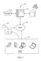
- FIG. 1 is a diagram illustrating a system, according to an example embodiment, for the real-time generation of an Online Analytical Processing (OLAP) cube.
- OLAP Online Analytical Processing
- FIG. 2 is a diagram of a Graphical User Interface (GUI), according to an example embodiment, illustrating a jurisdiction in which an entity files jurisdiction-specific tax data.
- GUI Graphical User Interface
- FIG. 3 is a diagram of a GUI, according to an example embodiment, illustrating a data entry page for a selected entity and a selected jurisdiction.
- FIG. 4 is a diagram of a GUI, according to an example embodiment, illustrating changes made to data included in the OLAP cube.
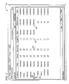
- FIG. 5 is a diagram of a GUI, according to an example embodiment, illustrating selectable event history for validated data.
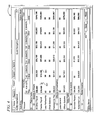
- FIG. 6 is a diagram of a GUI, according to an example embodiment, illustrating the editing of validated data.
- FIG. 7 is a diagram of a GUI, according to an example embodiment, illustrating a history of changes for cells in a table of an OLAP cube.
- FIG. 8 is a diagram of a GUI, according to an example embodiment, illustrating calculated apportionment factors.
- FIG. 9 is a block diagram of a computer system, according to an example embodiment, that is used to generate an OLAP cube with time stamped data stored as an event history.
- FIG. 10 is a block diagram of a computer system, according to an example embodiment, that is used to perform calculations using data and associated time stamps and event histories.
- FIG. 11 is a block diagram of a computer system, according to an example embodiment, for real-time generation of an OLAP cube that includes time stamped data.
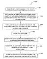
- FIG. 12 is a flow chart illustrating a method, according to an example embodiment, used to generate and store an OLAP cube with time stamping and an event history.
- FIG. 13 is a flow chart illustrating a method, according to an example embodiment, used to perform calculations on time stamped data within an OLAP cube so as to generate a snapshot of the data.
- FIG. 14 is a flow chart illustrating a method, according to an example embodiment, for the real-time generation and accessing of an OLAP cube.
- FIG. 15 is a flow chart illustrating an operation, according to an example embodiment, to build cube dimensions (e.g., accounts, entities, and jurisdictions) using validated data.
- cube dimensions e.g., accounts, entities, and jurisdictions
- FIG. 16 is a flow chart illustrating an operation, according to an example embodiment, to configure an OLAP cube using the built dimensions (e.g., accounts, entities and jurisdictions).
- built dimensions e.g., accounts, entities and jurisdictions.
- FIG. 17 is a flow chart illustrating an operation, according to an example embodiment, to use the user interface module to receive one or more queries from the client device.
- FIG. 18 is a diagram of the relationship of various data structures resulting from the execution of an operation, according to an example embodiment, to build a mapping index to allow the object in the dimension to be accessed.
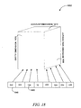
- FIG. 19 is database schema illustrating, according to an example embodiment, various tables associated with an account dimension of an OLAP cube.
- FIG. 20 is database schema illustrating, according to an example embodiment, various tables associated with an entity dimension of an OLAP cube.
- FIG. 21 is database schema illustrating, according to an example embodiment, various tables associated with attributes of an entity dimension of an OLAP cube.
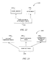
- FIG. 22 is database schema illustrating, according to an example embodiment, event history and attachment tables of an OLAP cube.
- FIG. 23 is database schema illustrating, according to an example embodiment, various tables associated with a main fact table of an OLAP cube.
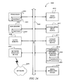
- FIG. 24 is a block diagram illustrating a diagrammatic representation of a machine in the example form of a computer system.
- a system and method is shown to establish a historical-factual basis for data.
- Data as used herein is validated data.
- Validated data include the data that have been examined by a person (e.g., a tax professional such as an auditor, Certified Public Accountant (CPA), or a Chief Financial Officer (CFO)) who certifies the data as valid with or without modifications. Certification may be in the form of tendering an opinion with regard to the data as to its validity. For example, if a tax auditor would like to see the history of how a certain piece of data has been updated over time, then an OLAP cube, as illustrated herein, is queried, and calculations (e.g., tax calculations) are performed using the data stored in this OLAP cube. These calculations reflect the validated data as it was understood at a particular point in time by a person (e.g., a natural person or legal entity) associated with the data.
- a person e.g., a natural person or legal entity
- Some example embodiments include the generating of a snap shot or “version” of the validated data as it was understood at some point in time, which is meant to include not only time of day but also calendar day or date including month, day and year or any combination thereof. This may be done by “time-stamping” individual items of data or sets of such data items from initiation and through modifications over time. Each snap shot or version, and data included therein, is used to perform calculations and may produce results attributable to and associable with that version and that “time.” The result of these calculations is used to understand certain historical business decisions of those (e.g., persons running a business) associated with the validated data and to track and reproduce the data, calculations and perhaps basis for the results.
- those e.g., persons running a business
- the invention may be used to over time create a plurality of versions of OLAP cube, data, and results, which may then be at a later date recreated without the need to discretely save each data set and OLAP cube build.
- the invention provides a way to build an OLAP cube using a time-based criterion, effectively recreating the cube, data, and results that would have been generated based on data as it existed at the selected point in time, like a virtual time-machine for data. Given that there are very large amounts of data associated with tax accounting and other applications and that conditions change over time (e.g., additional/fewer/different entities as a result of acquisition, sale, restructuring, etc.
- the present invention provides an efficient and effective system for 1) making real-time calculations and generating results, and 2) recreating the data and conditions that existed as of a particular point in time to build an OLAP cube consistent with those previous conditions.
- This is especially powerful in the areas of tax and accounting wherein filings are made with certain assumptions or rules and over time, for example due to rulings and audit decisions, etc., the data is modified to reflect changing conditions.
- An entity often is faced with the daunting task of going back to support earlier filings only to find that because data has been modified and/or other conditions have changed it may be costly, time-consuming and perhaps impossible to recreate the data and conditions that were valid at some point in time.
- the OLAP cube and related techniques herein allow entities to efficiently, and in a largely automated or semi-automated fashion, retrace its footsteps along the tax filing path. This can be done for companies comprising many legal entities with many subsidiaries, business units operating in a plurality of jurisdictions, including states and countries, and having thousands of tax related filings
- a system and method for generating and using time stamped data within an OLAP cube.
- This OLAP cube is part of a tax apportionment data system, wherein data for this OLAP cube is time stamped so as to determine the status of the data used in a tax-related calculation. This status is related to what data was considered valid data at a particular point in time. Further, time stamping allows for users to examine this data on a historical basis to discern the historical-factual basis for certain tax calculations.
- Some example embodiments illustrated herein include building a number of dimensions for an OLAP cube using validated data.
- the method includes configuring the OLAP cube based on the dimensions. Multiple aggregated data sets are generated and stored in a memory. Analytical processing of the OLAP cube data is performed based on one or more queries received from a client device.
- a historical-factual basis for validated data is established.
- This historical-factual basis has many uses. For example, if a tax auditor would like to see the history of how a certain data point has been updated over time, then the OLAP cube illustrated herein is queried, and calculations (e.g., tax calculations) performed using the data stored in this OLAP cube. These calculations reflect the data point as it was understood at a particular point in time by a person (e.g., a natural person or legal entity) associated with the data.
- the updating of the cube includes attaching documents to a fact data.
- a user may attach a legal opinion, a tax-related opinion, a section of the tax law, or other documents to a calculated tax item that has used that tax-related opinion or section of the tax law.
- the time stamping of the attachment is performed by generating an attachment record with attributes shown in the attachment table of Table 7, such as a TIMESTAMP attribute indicating a time when the attachment occurred.
- FIG. 1 is a high-level diagram depicting an example embodiment of a system 100 for real-time generation of an OLAP cube.
- the system 100 shown herein is part of a tax apportionment data management system.
- the system 100 includes an application server 110 , a relational database 115 , and an OLAP based database 120 linked via a network 150 .
- This network 150 includes the Internet, a Local Area Network (LAN), a Wide Area Network (WAN), or some other network of a suitable topology.
- LAN Local Area Network
- WAN Wide Area Network
- client device 130 e.g., a desktop computer, a laptop computer, a Personal Data Assistant (PDA), a cell phone, or other suitable networkable device.
- PDA Personal Data Assistant
- the connection between the client device 130 and the application server 110 may be a physical or logic connection utilizing one or more protocols outlined in the Transmission Control Protocol (TCP)/Internet Protocol (TCP/IP) stack model, or Open Systems Interconnection (OSI) model.
- the application server 110 may provide users of the client device 130 with a GUI 140 as rendered by the client device 130 .
- This GUI 140 may be a browser application (e.g., INTERNET EXPLORERTM, or FIREFOXTM) that interprets and renders web pages served up directly or indirectly by the application server 110 .
- the GUI 140 may be used as part of a stand-alone implementation of the system 100 and method shown herein.
- a stand-alone application includes the functionality of the system and method shown herein and the functionality of the GUI 140 residing on the same computer system.
- the application server 110 receives a number of data objects (e.g., including or relating to validated data) from the users.
- the application server 110 stores the facts in the database 115 .
- the facts relate to a corporate tax account, an investment portfolio, an administrative documentation, etc.
- the users create event histories by updating and validating facts through editing one or more attributes included in the facts at various times. Each event history may consist of a number of records.
- the user also selects a document 145 , using the GUI 140 , and associates the document 145 with an event history record. In an alternative example embodiment, the user may import from another system or database, or generate the document themselves.
- the application server 110 builds a number of dimensions (e.g., entity dimension, accounts dimension, jurisdiction dimension, tax-rule dimension, etc.) of a tax accounts OLAP cube, using validated data stored in the database 115 .
- the application server 110 configures the OLAP cube based on the dimensions.
- the application server 110 generates multiple aggregated sets of data (e.g., data associated with a fiscal year aggregated from data stored for various quarters of that fiscal year or sales in a region such as Europe aggregated from the sales data of various European countries).
- the application server 110 also performs analytical processes (e.g., calculations on one or more sets of OLAP cube data). Calculation results are stored in a memory (e.g., a Random Access Memory (RAM) of the application server 110 ). The calculations are performed based on one or more queries received from a client device 130 .
- RAM Random Access Memory
- the GUI 140 is used to receive updated tax data for use in an OLAP cube.
- This updated tax data is time stamped, as is more fully illustrated below.
- This updated tax data may be provided by a tax professional or other suitable person.
- the GUI 140 is used to display web pages including data relating to a tax apportionment management system.
- This functionality may include executing an “Enter Data” button, the use of a “History Mode” button and associated panel, and a variety of other functionalities.
- a button may be a screen object or widget.
- FIG. 2 is a diagram of the GUI 140 illustrating a list of jurisdictions in which an entity files income taxes, along with jurisdiction-specific data, such as the overall apportionment percentage.
- a graphical pointer 201 controlled by an input device, is used to select certain functionality that is displayed as part of the GUI 140 .
- a graphical pointer is a cursor.
- An input device includes a mouse, keyboard, light pen, touch screen, or other suitable input device. Select includes the execution of a right-click function, a mouse-over function, or a left-click function, through the use of the input device. Further, the input device is used to focus upon the functionality that is displayed as part of the GUI 140 . Focus indicates the component of the GUI 140 which is currently selected to receive input.
- a widget is an element of a GUI that displays an information arrangement changeable by the user, such as a check box, window or a text box.
- the graphical pointer 201 is used to execute a widget 202 that is used to expand or collapse data appearing on a screen.
- the data here relates to jurisdictions (e.g., the state of Georgia) and tax data associated with jurisdictions (e.g., jurisdiction-specific data).
- Check boxes 203 and 204 are used to select certain functionality associated with the jurisdiction. For example, through the selection of the check box 204 , the taxing regime associated with the United States Federal Interstate Income Tax Law (P.L. 86-272) can be applied to jurisdiction data.
- An over-all tax apportionment percentage is shown in field 205 , showing tax apportionment on a per state basis. Additionally, an enter data button 206 is shown that, when executed using the graphical pointer 201 , causes a next data entry screen (see e.g., FIG. 3 ) to be shown.
- FIG. 3 is a diagram of the GUI 140 illustrating a data entry page for a selected entity (e.g., Acme International), and selected jurisdictions in which this entity transacts business.
- a panel is opened where a user can change those selections and customize what data the user sees and can enter.
- the graphical pointer 201 can be used to select the tab 301 .
- the apportionment percentages can be emphasized for viewing (see e.g., 302 ). This emphasis for viewing may be in the form of bolding, italicizing, highlighting, or through the application of some other form of emphasis to the apportionment percentage.
- FIG. 4 is a diagram of a GUI 140 illustrating changes made to data included in the OLAP cube.
- data may be entered into a row or column of the GUI 140 .
- data is entered at 401 .
- the data is saved into the database 115 , or OLAP based database 120 , through the execution of the save button 402 . Further, the data that is entered or otherwise modified is emphasized for viewing.
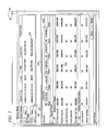
- FIG. 5 is a GUI 140 illustrating a selectable event history for validated data. Shown is the graphical pointer 201 that is used to select a button 501 . Through the selection of the button 501 , an event history is selected. Event histories may be scrolled through using the up arrow 503 or down arrow 504 . An event history summary is displayed at row 502 . The data in this row includes the user who made a change, comments by the user making the change, the time and date of the change, and the type of the change. Table 505 displays a break out of the event history and the specifics of the data associated with the event history. For example, at entry 506 an update is shown for the data as of a particular point in time. In addition, cells that were changed as part of an event are emphasized for viewing. In addition, the apportionment percentages are updated by re-calculating them using the input data as of that specific time.
- FIG. 6 is a GUI 140 illustrating the editing of validated data. Shown are various edits 601 - 607 for an event. Each edit is emphasized. Further, each edit is facilitated through the use of the graphical pointer 201 . These edits may be saved into the database 115 or the OLAP based database 120 . When doing so, the event history may be updated.
- FIG. 7 is a GUI 140 illustrating the history of change for cells in a table that is part of a dimension in an OLAP cube.
- a row 701 is selected using the graphical pointer 201 .
- a row 702 is selected and an edit history for this row displayed.
- This edit history is displayed in the popup 703 .
- an entry 704 showing the edit history (e.g., a complete history of changes) for the data displayed in the row 702 .
- every cell of a row has a hyperlink associated with it that, when executed, displays the edit history for the row.
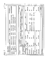
- FIG. 8 is a GUI 140 illustrating apportionment factor calculations.
- the graphical pointer 201 (not shown) is used to execute a jurisdiction heading at 801 , where a screen is shown that explains the details of how, for example, the apportionment factors (see 802) are calculated.
- the user can display the details for a specific factor (e.g., at 803 ) by clicking on its link.
- Special apportionment is distinguishable from standard apportionment, which is the process where federal taxable income adjusted to state basis is split and “apportioned” among various states based on the percentage of sales, property and payroll that occurred or is located in the various states.
- the sales, property and payroll in each given state are essentially divided by the total sales, property and payroll to determine the share of federal taxable income adjusted to state basis attributed to each of the particular states.
- special apportionment is the process of apportioning a given item of sales, property, payroll or other factor before including it in the state's factor numerator.
- a driver used in the apportionment computation may be referred to as a special apportionment method.
- the dollar value of an item that must be apportioned across states may be captured in a special apportionment account.
- An account may be associated with a legal entity (e.g., a corporation), a sub-entity (e.g., a service or a product line within a corporation), a flow-through entity (e.g., a partnership), etc.
- a legal entity e.g., a corporation
- a sub-entity e.g., a service or a product line within a corporation
- a flow-through entity e.g., a partnership
- Patent Publications 2003/0195780 (Arora et al.), 2008/0147527 (McIntyre et al.), 2007/0198390 (Lazear et al.), and 2007/0282761 (Deputy et al.) all of which are incorporated herein by reference.
- the system may be concerned with four dimensions, with special apportionment methods/rules being treated as a separate dimension. Multiple cubes may then be built in processing the various data and rules to arrive at the amount of each special apportionment account apportioned to each state in each entity.
- One exemplary process is 1) identify accounts subject to special apportionment and load the amounts subject to special apportionment in the different entities into a two-dimensional cube having entities and special apportionment accounts as dimensions; 2) establish or build a three-dimensional cube having jurisdictions, special apportionment accounts, and special apportionment methods as dimensions; 3) using 1) and 2) build a three-dimensional output cube comprised of entity, jurisdiction and special apportionment account dimensions that contains the amount of the accounts from 1) spread across states using the special apportionment methods specified in 2).
- the special apportionment methods to be used and associated with each jurisdiction specified in 2) may be as directed or specified by the respective state or may be selectable to greatest tax advantage by the entity.
- the invention and systems described herein are intended for use in the computation of foreign taxes and foreign tax credits.
- taxable income in each country is not determined by apportioning worldwide income across countries. Rather, each country taxes the income earned by an entity in that country and some of the income earned by foreign branches and subsidiaries of the entity (either at the time such income is earned or at the time it is remitted or distributed to the parent).
- the present invention may be used in an international context by configuring an OLAP cube with jurisdiction, account, and entity dimensions. The jurisdiction dimension of the OLAP cube will be comprised of countries rather than the individual U.S. states. In one alternative, for example in the case of a U.S.
- the jurisdiction dimension may have both countries (U.S. and foreign) as well as political subdivisions of these countries (such as U.S. states and German “Lander”).
- the entity dimension may include not only legal entities, e.g., corporations and partnerships, but also “branches” or “permanent establishments” of such legal entities in the different countries.
- the system may be used to build multiple OLAP cubes, e.g., one for the U.S. and one for foreign.
- one comprehensive OLAP cube may be configured that includes U.S. and foreign entities, jurisdictions, accounts, etc.
- An international tax rules dimension may be built to process the various tax rules of the countries and may be applied in a separate cube.
- the time-stamping function associated with the OLAP cube and system disclosed herein may be particularly beneficial to companies that are involved in audits on a routine basis to help establish to the various tax authorities that at the time of the filings the data used to arrive at the tax filing was the proper data for use at that time. For example, if a federal tax ruling results in some adjustment, such as disallowance of a deduction, then federal taxable income will increase. As a result, a later calculation of state tax liability may yield a liability that differs from the one obtained when the entity originally filed its state return. It is important for companies to be able to track versions of data, including income data, entity data (for example over time additional entities may be formed), etc. to ensure compliance and avoid penalties, fines and the like.
- FIG. 9 is a block diagram of an example computer system 900 that is used to generate an OLAP cube with time stamped data stored as an event history.
- the blocks shown herein may be implemented in software, firmware, or hardware. These blocks may be directly or indirectly communicatively coupled via a physical or logical connection.
- the computer system 900 may be the application server 110 . Shown are blocks 901 through 907 . Illustrated is a receiver 901 to receive data that includes a time stamp. Communicatively coupled to the receiver 901 is a cube building engine 902 to build an OLAP cube that includes a dimension, the dimension acting as a schema for the data that includes the time stamp.
- Communicatively coupled to the cube building engine 902 is an object population engine 903 to populate the OLAP cube with an object, the object including the data and the time stamp as at least one attribute.
- Communicatively coupled to the object population engine 903 is a storage engine 904 to store the OLAP cube.
- Communicatively coupled to the storage engine 904 is a data modification engine 905 to modify the data to create modified data, the modification categorized as an event.
- Communicatively coupled to the data modification engine 905 is an association engine 906 to associate an additional time stamp with the modified data to reflect the time of the event.
- Communicatively coupled to the association engine 906 is an event aggregation engine 907 to store the event into an event history, the event history including the time of the event.
- the OLAP cube is stored into Random Access Memory (RAM).
- the dimension includes at least one of an entity dimension, an account dimension, or a jurisdiction dimension.
- FIG. 10 is a block diagram of an example computer system 1000 that is used to perform calculations using data and associated time stamps and event histories.
- the blocks shown herein may be implemented in software, firmware, or hardware. These blocks may be directly or indirectly communicatively coupled via a physical or logical connection.
- the computer system 1000 may be one of the client devices 130 . Shown are blocks 1001 through 1004 . Illustrated is a cube retrieval engine 1001 to retrieve an OLAP cube populated with an object, the object including a time attribute and a data attribute. Communicatively coupled to the cube retrieval engine 1001 is a calculation engine 1002 to perform a calculation using data retrieved from the data attribute, the calculation reflecting the data at a time defined by the time attribute.
- Communicatively coupled to the calculation engine 1002 is a display 1003 to display a result of the calculation for the time.
- the calculation engine 1002 performs a second calculation, the second calculation using the data retrieved from the data attribute, and the second calculation reflecting the data at an additional time defined by an additional time attribute.
- the time and the additional time are part of an event history for the data, the event history including a history of modifications made to the data.
- the OLAP cube includes dimensions that include at least one of an entity dimension, an account dimension, or a jurisdiction dimension.
- Communicatively coupled to the display 1003 is a query engine 1004 to query the OLAP cube through the use of a Multidimensional Expression (MDX) language.
- MDX Multidimensional Expression
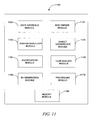
- FIG. 11 is a block diagram illustrating an example embodiment of a system 1100 for real-time generation of an OLAP cube that includes time stamped data.
- the various blocks outlined in FIG. 11 may be implemented in software, hardware, or firmware. Additionally, these blocks may be implemented as part of the aforementioned application server 110 , client device 130 , or some other suitable device.
- the system 1100 may include a user interface module 1120 , an MDX parser 1130 , an object interpreter module 1135 , a dimension builder module 1140 , a cube builder module 1150 , an aggregation module 1160 , a processing module 1170 , an Event History (EH) generating module 1180 , and a memory module 1190 .
- EH Event History
- the dimension builder module 1140 creates a number of dimensions for an OLAP cube using the validated data stored in the database 115 .
- the OLAP cube has three primary dimensions.
- the three primary dimensions of the tax accounts OLAP cube include accounts, entities and jurisdictions.
- Each dimension includes a number of tables.
- the accounts dimension includes a const-factor-type table 1910 , a parent-account table 1920 , an account table 1930 , and an account-fact table 1940 , which may be aggregated to account dimension tables 1950 .
- the structure of the account dimension tables 1950 is shown in Table 2 below.
- the entity dimension includes an entity table 2010 , an entity-fact table 2020 , and a group-fact table 2030 , forming entity dimension tables 2050 (see FIG. 20 below).
- the detailed structure of these tables is seen in Table 4 below.
- Each dimension may include a number of members having attribute tables.
- the members of the entity dimension tables 2050 may include an entity-filing table 2150 , a group-filing table 2130 , a group-member-fact table 2120 , an ownership table 2110 , an ownership percentage table 2140 , and a flow-through-rule-fact table 2160 , aggregated under members of entity dimension attribute tables 2170 shown in FIG. 21 below.
- the attributes of these tables are shown in Table 5 below. Attributes of the jurisdiction dimension are provided in Table 2 below.
- user interface module 1120 has functionality similar to display 1003 . “Similar” includes “the same as.” Additionally, dimension builder module 1140 has functionality similar to association engine 906 . Object interpreter module 1135 has functionality similar to object population engine 903 . Aggregation module 1160 is similar to event aggregation engine 907 . Cube builder module 1150 is similar to cube retrieval engine 1001 and cube building engine 902 . EH generating module 1180 is similar to data modification engine 905 . Processing module 1170 is similar to calculation engine 1002 . Memory module 1190 is similar to storage engine 904 .
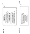
- FIG. 12 is a flow chart illustrating an example method 1200 used to generate and store an OLAP cube with time stamping and an event history. Shown are various operations 1201 through 1207 that may be executed upon the application server 110 . Shown is an operation 1201 that, when executed, receives data that includes a time stamp. Operation 1202 is executed to build an OLAP cube that includes a dimension, the dimension acting as a schema for the data that includes the time stamp. Operation 1203 is executed to populate the OLAP cube with an object, the object including the data and the time stamp as at least one attribute. Operation 1204 is executed to store the OLAP cube. Operation 1205 is executed to modify the data to create modified data, the modifying categorized as an event.
- Operation 1206 is executed to associate an additional time stamp with the modified data to reflect a time of the event.
- Operation 1207 is executed to store the event into an event history, the event history including the time of the event.
- the OLAP cube is stored into RAM.
- the dimension includes at least one of an entity dimension, an account dimension, or a jurisdiction dimension.
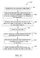
- FIG. 13 is a flow chart illustrating an example method 1300 used to perform calculations on time stamped data within an OLAP cube so as to generate a snapshot of the data. Shown are various operations 1301 through 1305 that may be executed upon the client devices 130 . Shown is an operation 1301 that, when executed, retrieves an OLAP cube populated with an object, the object including a time attribute and a data attribute. Operation 1302 is executed to perform a calculation using data retrieved from the data attribute, the calculation reflecting the data at a time defined by the time attribute. Operation 1303 is executed to display a result of the calculation for the time.
- Operation 1304 is executed to perform a second calculation using the data retrieved from the data attribute, the second calculation reflecting the data at an additional time defined by an additional time attribute.
- the time and the additional time are part of an event history for the data, the event history including a history of modifications made to the data.
- the OLAP cube includes dimension that include at least one of an entity dimension, an account dimension, or a jurisdiction dimension.
- Operation 1305 is executed to query the OLAP cube using the MDX language.
- FIG. 14 is a flow chart illustrating an example method 1400 for real-time generation and accessing of an OLAP cube.
- Operations 1410 through 1430 may be executed by the application server 110 .
- Operation 1440 may be executed by one or more of the client devices 130 , or the application server 110 .
- the method 1400 is initiated at operation 1410 , where the dimension builder module 1140 builds cube dimensions (e.g., accounts, entities, and jurisdictions) using validated data.
- the cube builder module 1150 configures an OLAP cube, such as the tax accounts OLAP cube, using the built dimensions (e.g., accounts, entities and jurisdictions). Since the data used to build the dimensions are validated data, the OLAP cube built using those dimensions may also be a validated OLAP cube.
- the aggregation module 1160 aggregates sets of data to generate collective data sets. For example, the aggregation module 1160 aggregates an entity table, an entity-fact table, and the group-fact table to obtain the entity dimension tables (see FIG. 20 below).
- the user interface module 1120 receives one or more queries from the client device 130 . The queries may be parsed by the MDX parser module 1130 to identify input data and a set of demanded data from the queries' contents.
- the processing module 1170 performs a number of calculations and stores the results in RAM before receiving queries.
- the processor selects the desired result from the stored results and makes it available to the user interface module 1120 to present the result to the user.
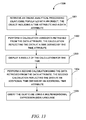
- FIG. 15 is a flow chart illustrating an example operation 1410 . Shown is an operation 1501 that, when executed, receives selection input to select dimensions to be used to build an OLAP cube. These dimensions may include an account dimension, entity dimension, or a jurisdiction dimension.
- a decisional operation 1502 is executed to determine whether additional dimensions have been selected. In cases where decisional operation 1502 evaluates to “false,” the operation 1501 is re-executed. In cases where decisional operation 1502 evaluates to “true,” an operation 1503 is executed. Operation 1503 is executed to retrieve validated data from the database 115 . Operation 1504 is executed to instantiate an object or objects using the retrieved validated data.
- the object(s) includes an attribute (e.g., data), and a method that may utilize the attribute.
- This data may include a time stamp of other event history data.
- Operation 1505 is executed to populate the dimension with the object(s).
- the object(s) may be an entry in a table that is part of the dimension, where the object(s) is referenced via a unique ID value.
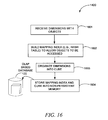
- FIG. 16 is a flow chart illustrating an example operation 1420 . Shown is an operation 1420 that includes an operation 1601 . Operation 1601 , when executed, receives a dimension with an object or objects. Operation 1602 is executed to build a mapping index to allow the object(s) in the dimension to be accessed.
- a mapping index may be a hash table, binary search tree, or some other suitable data structure that allows for amortized ⁇ (1), or ⁇ (n log n) performance.
- a hash table includes a unique ID value for the object(s) as a key value to be used to access the dimension.
- This unique ID value may be numeric value such as an integer, or an alpha-numeric value such as a string that allows for the object(s) to be distinguished from another object. Access to the object(s) included in the dimension may be via a pointer, referent, or some other value that refers directly to another value stored elsewhere in the memory of a computer.
- Operation 1603 is executed to organize the dimension along with other dimensions into an OLAP cube.
- Operation 1604 is executed to store the mapping index and OLAP cube into some type of non-persistent memory such as RAM.
- the mapping index and OLAP cube are stored into some type of persistent memory such as the OLAP based database 120 .
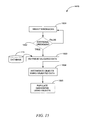
- FIG. 17 is a flow chart illustrating an example operation 1440 . Shown is an operation 1702 that, when executed, parses a query 1701 .
- This query 1701 may be an MDX based query requesting information from an OLAP cube. Further, this query 1701 identifies an object ID and time.
- Operation 1703 is executed to query an OLAP cube using the query 1701 in conjunction with the mapping index and time value.
- Operation 1704 is executed to perform calculations using the attributes of the object retrieved based upon the object ID and time value. This calculation may be a tax calculation, accounting calculation, or some other suitable type of calculation.
- a decisional operation 1705 is shown that determines whether the results of the calculation should be displayed in the GUI 140 .
- decisional operation 1705 evaluates to “true,” the calculation results are displayed in a display 1706 that is part of the GUI 140 .
- a display is a frame or sub-frame of a display area.
- decisional operation 1705 evaluates to “false”
- a further decisional operation 1707 is executed.
- Decisional operation 1707 determines whether the validated data has been modified. Validated data is modified where the object including the validated data, or the validated data itself is changed, examined, reviewed, or accessed.
- an operation 1708 is executed to store the validated data into a dimension included in the OLAP cube.
- an operation 1709 is executed.
- Operation 1709 is executed to receive validated data in the form of the document 145 .
- the validated data is received from another source such as exported from a database, provided by a user, or from some suitable other source.
- Operation 1710 is executed to associate a start time with the validated data, denoting the time during which the data is valid.
- Operation 1711 is executed to associate an end time with the validated data, denoting a time after which the validity of the data can no longer be assumed.
- Operation 1712 is executed to update the database 115 with the modified validated data.
- FIG. 18 is a diagram of the relationship of various data structures resulting from the execution of operation 1602 . Illustrated is an OLAP cube with an account dimension 1810 , entity dimension 1820 , and jurisdiction dimension 1830 .
- Mapped to this OLAP cube is a hash table 1840 that includes at least one the object IDs 1850 . These object IDs 1850 are used to access the OLAP cube and object(s) included therein. These object IDs may be a pointer, referent, or other suitable way to access the object.
- This hash table serves as a mapping index to the OLAP cube.
- Some embodiments may include the various databases (e.g., databases 115 and 120 ) being relational databases, or in some cases as OLAP based databases.
- relational databases various tables of data are created and data is inserted into, and/or selected from, these tables using a Structured Query Language (SQL), or some other database-query language known in the art.
- SQL Structured Query Language
- OLAP databases one or more multi-dimensional cubes or hyper-cubes including multidimensional data from which data is selected from or inserted into, using MDX or some object-based query language, may be implemented.
- a database application such as, for example, MYSQLTM, SQLSERVERTM, Oracle 81TM, 10GTM, or some other suitable database application may be used to manage the data.
- a database using cubes and MDX a database using Multidimensional Online Analytic Processing (MOLAP), Relational Online Analytic Processing (ROLAP), Hybrid Online Analytic Processing (HOLAP), or some other suitable database application may be used to manage the data.
- MOLAP Multidimensional Online Analytic Processing
- ROLAP Relational Online Analytic Processing
- HOLAP Hybrid Online Analytic Processing
- These tables, or cubes made up of tables, in the case of, for example, ROLAP may be organized into a RDS or Object Relational Data Schema (ORDS), as is known in the art.
- RDS Relational Data Schema
- RDS Object Relational Data Schema
- These schemas may be normalized using certain normalization algorithms so as to avoid abnormalities such as non-additive joins and other problems. Additionally, these normalization algorithms may include Boyce-Codd normal form or some other normalization optimization algorithm known in the art.
- the various modules and methods outlined above are used to build and access an OLAP cube that has an event history associated with the validated data included in the OLAP cube.
- the user interface module 1120 receives a number of facts (e.g., an account data fact, from users of the application server 110 ). The users may provide these facts directly to the application server 110 , or via a web-based link using the GUI 140 . The GUI 140 may also be generated and supported by the user interface module 1120 . The facts may also be imported to the application server from the database 115 . The user may update and validate data (e.g., facts, fact tables, and fact attributes) stored in the database 115 .
- the example account data facts include a number of attributes (e.g., JURISDICTION_ID, ENTITY_ID, PARENT_NAME, etc.), and each attribute has characteristics such as data-type, nullable, and primary key, as shown in Table 1 below.
- the JURISDICTION_ID and ENTITY_ID use foreign keys that link ACCOUNT_DATA_FACTS with tables associated with jurisdiction and entity dimensions, respectively.
- a TRANSACTIONTIMEEND attribute is provided that includes the ending time that data (e.g., data in the form of a tuple) was entered into Table 1.
- a TRANSACTIONTIMESTART attribute is provided that includes the start time that data (e.g., data in the form of a tuple) was entered into Table 1.
- the BEGINNING VALUE and ENDVALUE attributes may reflect the value of a fact data entry (e.g., data in the form of a tuple) for a corresponding time period during which the fact data was valid (e.g., existed as validated data). Additionally, in some example cases, tuple entries for the BEGINNING VALUE and ENDVALUE attributes may be cumulatively updated with previous tuple entries. These tuple entries may include data relating to tax data. This updating may include the modification of a field of a data structure. Collectively, the TRANSACTIONTIMEEND and TRANSACTIONTIMESTART may provide a historical basis for data included in the BEGINVALUE and ENDVALUE.
- the dimension builder module 1140 may also build another example dimension (e.g., tax rule dimension, for the tax accounts OLAP cube). Example attributes of this member are shown in Table 6 below.
- the dimension builder module 1140 may load the data to be used for each dimension in to the memory module 1190 (e.g., a random access memory in the application server 110 or the client device 130 ).
- the users may update data in the database 115 by editing or validating the data or by attaching documents to facts.
- the EH generating module 1180 may generate an event history record.
- Event histories and attachments may include attributes, examples of which are shown in Table 7 below.
- an updated cube e.g., a current cube
- the MAX_TIME may include a maximum allowable date in the database specified by the vendor providing the database.
- the cube builder module 1150 may use the dimensions built by the dimension builder module 1140 to configure the tax accounts OLAP cube. Once the OLAP cube is built, it may be saved in the OLAP based database 120 of FIG. 1 .
- the aggregation module 1160 may generate aggregate sets of data. According to an example embodiment, portions of the tax accounts OLAP cube may be aggregated, and/or entity filings for a corporate entity may be aggregated.
- the aggregation module 1160 may also aggregate various data tables. For example, the aggregation module 1160 may aggregate an event history table 2210 with the attachment table 2220 to form the event history and attachment tables 2230 (see FIG. 22 ).
- the user interface module 1120 may receive one or more queries from the client device 130 .
- the user interface module 1120 may pass these queries to the MDX parser module 1130 .
- the MDX parser module 1130 may parse the queries to identify various input data contents of the query.
- the query may demand a number of data elements that may be non-existing in the database 115 and 120 .
- the processing module 1170 may calculate the non-existing data elements, based on the stored data in an OLAP cube, according to one or more procedures or methods.
- the object interpreter module 1135 may translate the MDX queries into an object query, so that the processing module 1170 may perform calculations based on objects.
- the processing module 1170 may store the results in the memory module 1190 .
- the processing module 1170 may discard intermediary data resulting from various calculations, thereby saving large amounts of storage space (e.g., the volume of intermediary data may often amount to more than 10 times the results). In other words, any data that is derivable from the input data may not be saved.
- FIG. 19 is a database schema 1900 illustrating, according to an example embodiment, various tables associated with an account dimension of an OLAP cube.
- the account dimension tables may include the const-factor-type table 1910 , the parent-account table 1920 , the account table 1930 , and the account-fact table 1940 , which may be aggregated to the account dimension tables 1950 .
- Table 3 shows the structure of the account dimension tables 1950 .
- FIG. 20 is a database schema 2000 illustrating, according to an example embodiment, various tables associated with an entity dimension of an OLAP cube.
- the schema 2000 may include the entity table 2010 , the entity-fact table 2020 , and the group-fact table 2030 forming the entity dimension tables 2050 .
- the detailed structure of these tables is seen in Table 4 below.
- FIG. 21 is a database schema 2100 illustrating, according to an example embodiment, various tables associated with members of the entity dimension of FIG. 5 , including entity-filing table 2150 , group-filing table 2130 , group-membership-fact table 2120 , ownership table 2110 , ownership percentage table 2140 , and flow-through-rule-fact table 2160 aggregated under members of an entity dimension attribute tables 2170 .
- entity-filing table 2150 entity-filing table 2150
- group-filing table 2130 group-membership-fact table 2120
- ownership table 2110 e.g., ownership percentage table 2140
- flow-through-rule-fact table 2160 aggregated under members of an entity dimension attribute tables 2170 .
- the attributes of these tables are shown in Table 5.
- the tax accounts OLAP may include another dimension, tax rule dimension, built by the dimension builder module 1140 .
- the attribute tables for members of tax rule dimension are shown in Table 6.
- the attribute tables are linked with the event-history table via the event ID attribute shown in these tables.
- There are other cross-linking attributes shown in Table 6 such as JURISDICTION_ID attribute or ENTITY_ID attribute that connect Table 3 with 2 and 4, respectively.
- FIG. 22 is a database schema 2200 illustrating, according to an example embodiment, event history and attachment tables of an OLAP cube.
- the schema 2200 includes the event-history table 2210 and the attachment table 2220 . These tables may be aggregated by the aggregation module 1160 to form the event-history & attachment tables 2230 .
- the attributes of these tables are shown in Table 7.
- the event-history table 2210 and the attachment table 2220 are linked via the event ID attribute, which is shown in both tables.
- FIG. 23 is a database schema 2300 illustrating, according to an example embodiment, various tables associated with a main fact table of an OLAP cube.
- the main fact table 2310 is related to the account dimension tables 2320 , entity dimension table 2330 , and the jurisdiction dimension table 2340 .
- the attribute ACCOUNT NAME may be the linking attribute between the main fact table 2310 and the account dimension tables 2320 .
- the cross-linking between the main fact table 2310 and the entity dimension table 2320 may be provided by the ENTITY_ID attribute.
- the main fact table 2310 may be linked to the jurisdiction dimension table 2340 via the JURISDICTION_ID attribute.
- FIG. 24 illustrates a diagrammatic representation of a machine in the example form of a computer system 2400 within which a set of instructions may be executed to cause the machine to perform any one or more of the methodologies discussed herein.
- the machine operates as a standalone device or may be connected (e.g., networked) to other machines.
- the machine may operate in the capacity of a server or a client machine in server-client network environment, or as a peer machine in a peer-to-peer (or distributed) network environment.
- the machine may be a server computer, a client computer, a Personal Computer (PC), a tablet PC, a Set-Top Box (STB), a Personal Digital Assistant (PDA), a cellular telephone, a web appliance, a network router, switch or bridge, or any machine capable of executing a set of instructions (sequential or otherwise) that specify actions to be taken by that machine.
- PC Personal Computer
- PDA Personal Digital Assistant
- STB Set-Top Box
- a cellular telephone a web appliance
- network router switch or bridge
- the example computer system 2400 includes a processor 2402 (e.g., a Central Processing Unit (CPU), a Graphics Processing Unit (GPU), or both), a main memory 2401 and a static memory 2406 , which communicate with each other via a bus 2408 .
- the computer system 2400 may further include a video display unit 2410 (e.g., a Liquid Crystal Display (LCD) or a Cathode Ray Tube (CRT)).
- LCD Liquid Crystal Display
- CRT Cathode Ray Tube
- the computer system 2400 also includes an alphanumeric input device 2417 (e.g., a keyboard), a cursor control device 2411 (e.g., a mouse), a drive unit 2416 (e.g., hard-disk drive), a signal generation device 2418 (e.g., a speaker) and a network interface device 2420 .
- an alphanumeric input device 2417 e.g., a keyboard
- a cursor control device 2411 e.g., a mouse
- a drive unit 2416 e.g., hard-disk drive
- signal generation device 2418 e.g., a speaker
- the drive unit 2416 includes a machine-readable medium 2422 on which is stored one or more sets of instructions (e.g., software) 2421 embodying any one or more of the methodologies or functions described herein.
- the instructions 2421 may also reside, completely or at least partially, within the main memory 2401 and/or within the processor 2402 during execution thereof by the computer system 2400 , the main memory 2401 and the processor 2402 also constituting machine-readable media.
- the instructions 2421 may further be transmitted or received over a network 2426 via the network interface device 2420 .
- machine-readable medium 2422 is shown in an example embodiment to be a single medium, the term “machine-readable medium” should be taken to include a single medium or multiple media (e.g., a centralized or distributed database, and/or associated caches and servers) that store the one or more sets of instructions.
- the term “machine-readable medium” shall also be taken to include any medium that is capable of storing, encoding or carrying a set of instructions for execution by the machine and that cause the machine to perform any one or more of the methodologies of the present invention.
- the term “machine-readable medium” shall accordingly be taken to include, but not be limited to, solid-state memories, optical and magnetic media, and carrier wave signals.
- Some embodiments may utilize the OSI basic reference model or TCP/IP protocol stack model for defining the protocols used by a network to transmit data. Operation 1410 and 1440 may use these protocols.
- a system of data transmission between a server and client, or between peer computer systems is illustrated as a series of roughly five layers comprising: an application layer, a transport layer, a network layer, a data link layer, and a physical layer.
- the various tiers e.g., the interface, logic, and storage tiers
- data from an application residing at the application layer is loaded into the data load field of a TCP segment residing at the transport layer.
- This TCP segment also includes port information for a recipient software application residing remotely.
- This TCP segment is loaded into the data load field of an IP datagram residing at the network layer.
- this IP datagram is loaded into a frame residing at the data link layer.
- This frame is then encoded at the physical layer, and the data transmitted over a network such as an internet, LAN, WAN, or some other suitable network.
- internet refers to a network of networks. These networks may use a variety of protocols for the exchange of data, including the aforementioned TCP/IP, or some other suitable protocol. These networks may be organized within a variety of topologies (e.g., a star topology), or structures.
Abstract
Description
- This is a non-provisional patent application claiming priority under 35 USC §119(e) to U.S. Provisional Patent Application No. 61/038,745, filed on Mar. 22, 2008, entitled, “ONLINE ANALYTIC PROCESSING CUBE WITH TIME STAMPING,” which is incorporated by reference in its entirety.
- Example embodiments relate generally to the technical field of data management, and in one specific example, to a system and a method for time stamping data.
- As companies continue to strive for efficiency, consistency and flexibility, computers and software executed on computers are increasingly relied upon to automate, semi-automate, enhance, quicken and make reliable and uniform business processes. As a result of rapidly expanding and increasingly cost-effective data storage and management capabilities and ever-increasing bandwidth in data communications, the appetite for increasingly robust software programs with greater access and use of business data has grown. Tax data may often be stored in computer databases where various operations may be readily performed upon the data, using the vast processing power of today's computer systems. A variety of tax software may assist individual or corporate accountants to prepare accurate tax documents. Many tax software applications are capable of importing required financial data related to accounts from databases of various financial institutions such as banks, mortgage companies, investment institutes, etc.
- The convergence of SOX 404 and FASB Interpretation No. 48 (FIN 48) presents tax departments with an unprecedented level of process, documentation, and control requirements. To ensure compliance with FIN 48, tax departments are faced with the need to create a controlled and auditable environment that supports: processes and controls around managing tax positions across the entire organizational structure, all jurisdictions, and over multiple years; the development of a comprehensive inventory of tax positions (certain and uncertain) and balances; judgments regarding the technical merits of the positions; measurement of the appropriate impact to be reported in the financial statements; detailed documentation to be tracked for supporting the judgments around positions and their measured benefit; and new and substantive financial statement disclosures. In addition, with FIN 48, the assessment of the inventory of tax positions is a continual process. With each quarterly financial reporting cycle, decisions regarding the technical merits and proper measurements must be reevaluated, thus requiring the ability to capture and track ongoing analysis, approvals, and related documentation supporting decisions made throughout the process. What is needed is a system that addresses these process, control, and documentation requirements by providing a secure, controlled framework for identifying, evaluating, measuring, and reporting on tax positions—across entities, jurisdictions, and periods—in accordance with FIN 48 and other standards. Existing spreadsheet-based systems and document management tools fall short of facilitating multiple layers of decision making, reducing manual effort, supporting internal controls, and complementing existing tax provision processes. A need exists for a system to help companies comply with the process, documentation, and control requirements of FIN 48; streamline the preparation for, and process of, financial audits; reduce risk, increase accuracy, and improve tax department efficiency and effectiveness; adhere to company-defined SOX 404 controls and FIN 48 processes through a highly configurable, secure, and fully auditable framework.
- In one exemplary embodiment, the invention provides a computer-implemented method for performing tax calculations. The method includes: receiving data that includes a time stamp, the data for use in performing tax calculations; building an Online Analytical Processing (OLAP) cube that includes a dimension, the dimension acting as a schema for the data that includes the time stamp; populating the OLAP cube with an object, the object including the data and the time stamp as at least one attribute; storing the OLAP cube; and using the OLAP cube to perform tax calculations and to generate a tax related data set, whereby using a time-based criteria the OLAP cube may be restored at a later date and after modifications to the data have occurred. In addition, the method may include modifying the data to create modified data, the modifying categorized as an event; and associating an additional time stamp with the modified data to reflect a time of the event; and/or storing the event into an event history, the event history including a time of the event. The data may represents a first data version and the modified data may represent a second data version and the OLAP cube may represent a first OLAP cube version, with the method further comprising: building a second OLAP cube version by populating the second OLAP cube version with an object that includes the second data version and the additional time stamp; and using the second OLAP cube version to perform tax calculations and to generate a second tax related data set different from the first tax related data set. The method may further include building a plurality of OLAP cube versions respectively using a plurality of data versions to respectively generate a plurality of tax related data sets and/or using a time-based criteria to selectively build one of the plurality of OLAP cube versions based on time-stamp data associated with the plurality of data versions.
- In second exemplary embodiment, the invention provides a computer-implemented method for performing tax calculations, the method comprising: retrieving an Online Analytical Processing (OLAP) cube populated with an object, the object including a time attribute and a data attribute; performing a tax related calculation using the OLAP cube and data retrieved from the data attribute, the calculation reflecting the data at a time defined by the time attribute; and displaying a result of the calculation associated with the time, the result including a tax related data set. The method may further comprising performing a second calculation using the data retrieved from the data attribute, the second calculation reflecting the data at a second time defined by a second time attribute.
- In yet another exemplary embodiment the invention provides a computer system for processing tax related data in performing tax calculations, the system comprising: a receiver to receive tax related data that includes a time stamp; a cube building engine to build an Online Analytical Processing (OLAP) cube that includes a dimension, the dimension acting as a schema for the tax related data that includes the time stamp; an object population engine to populate the OLAP cube with an object, the object including the tax related data and the time stamp as at least one attribute; a storage engine to store the OLAP cube; and a processor adapted to use the OLAP cube to perform tax calculations and to generate a tax related result data set. The computer system may, after the tax related dated has been modified, utilize the processor to receive and process a time-based criteria to cause the cube building engine to build the OLAP cube using pre-modified tax related data based at least in part on the time stamp to thereby perform tax calculations to generate the tax related data set.
- In yet another exemplary embodiment, the invention provides a computer system for processing tax related data in performing tax calculations, the system comprising: a cube retrieval engine to retrieve an Online Analytical Processing (OLAP) cube populated with an object, the object including a time attribute and a data attribute; a tax calculation engine to perform a tax related calculation using tax related data retrieved from the data attribute, the tax related calculation reflecting the tax related data at a time defined by the time attribute; and a display to display a tax related result of the calculation associated with the time. The tax calculation engine may perform a second tax calculation, the second tax calculation uses the tax related data retrieved from the data attribute, and the second tax calculation reflects the tax related data at a second time defined by a second time attribute. In addition, the time and the second time may be part of an event history for the tax related data, the event history including a history of modifications made to the tax related data.
- In yet another exemplary embodiment, the invention provides an apparatus comprising: means for retrieving an Online Analytical Processing (OLAP) cube populated with an object, the object including a time attribute and a data attribute; means for processing the OLAP cube to and performing a tax calculation using tax related data retrieved from the data attribute, the tax calculation reflecting the tax related data at a time defined by the time attribute; and means for displaying a tax related result of the tax calculation associated with the time.
- In yet another exemplary embodiment the invention provides a machine-readable medium comprising instructions, which when implemented by one or more machines, cause the one or more machines to perform the following operations: retrieve an Online Analytical Processing (OLAP) cube populated with an object, the object including a time attribute and a data attribute; perform a tax calculation using tax related data retrieved from the data attribute, the tax calculation reflecting the tax related data at a time defined by the time attribute; and display a tax related result of the tax calculation associated with the time. The machine-readable medium instructions may also be adapted to perform the additional operation of performing a second tax calculation using modified tax related data, the second tax calculation reflecting the modified tax related data at a second time defined by the time attribute.
- In order to facilitate a full understanding of the present invention, reference is now made to the accompanying drawings, in which like elements are referenced with like numerals. These drawings should not be construed as limiting the present invention, but are intended to be exemplary and for reference. Some embodiments are illustrated by way of example and not limitation in the figures of the accompanying drawings in which:
-
FIG. 1 is a diagram illustrating a system, according to an example embodiment, for the real-time generation of an Online Analytical Processing (OLAP) cube. -
FIG. 2 is a diagram of a Graphical User Interface (GUI), according to an example embodiment, illustrating a jurisdiction in which an entity files jurisdiction-specific tax data. -
FIG. 3 is a diagram of a GUI, according to an example embodiment, illustrating a data entry page for a selected entity and a selected jurisdiction. -
FIG. 4 is a diagram of a GUI, according to an example embodiment, illustrating changes made to data included in the OLAP cube. -
FIG. 5 is a diagram of a GUI, according to an example embodiment, illustrating selectable event history for validated data. -
FIG. 6 is a diagram of a GUI, according to an example embodiment, illustrating the editing of validated data. -
FIG. 7 is a diagram of a GUI, according to an example embodiment, illustrating a history of changes for cells in a table of an OLAP cube. -
FIG. 8 is a diagram of a GUI, according to an example embodiment, illustrating calculated apportionment factors. -
FIG. 9 is a block diagram of a computer system, according to an example embodiment, that is used to generate an OLAP cube with time stamped data stored as an event history. -
FIG. 10 is a block diagram of a computer system, according to an example embodiment, that is used to perform calculations using data and associated time stamps and event histories. -
FIG. 11 is a block diagram of a computer system, according to an example embodiment, for real-time generation of an OLAP cube that includes time stamped data. -
FIG. 12 is a flow chart illustrating a method, according to an example embodiment, used to generate and store an OLAP cube with time stamping and an event history. -
FIG. 13 is a flow chart illustrating a method, according to an example embodiment, used to perform calculations on time stamped data within an OLAP cube so as to generate a snapshot of the data. -
FIG. 14 is a flow chart illustrating a method, according to an example embodiment, for the real-time generation and accessing of an OLAP cube. -
FIG. 15 is a flow chart illustrating an operation, according to an example embodiment, to build cube dimensions (e.g., accounts, entities, and jurisdictions) using validated data. -
FIG. 16 is a flow chart illustrating an operation, according to an example embodiment, to configure an OLAP cube using the built dimensions (e.g., accounts, entities and jurisdictions). -
FIG. 17 is a flow chart illustrating an operation, according to an example embodiment, to use the user interface module to receive one or more queries from the client device. -
FIG. 18 is a diagram of the relationship of various data structures resulting from the execution of an operation, according to an example embodiment, to build a mapping index to allow the object in the dimension to be accessed. -
FIG. 19 is database schema illustrating, according to an example embodiment, various tables associated with an account dimension of an OLAP cube. -
FIG. 20 is database schema illustrating, according to an example embodiment, various tables associated with an entity dimension of an OLAP cube. -
FIG. 21 is database schema illustrating, according to an example embodiment, various tables associated with attributes of an entity dimension of an OLAP cube. -
FIG. 22 is database schema illustrating, according to an example embodiment, event history and attachment tables of an OLAP cube. -
FIG. 23 is database schema illustrating, according to an example embodiment, various tables associated with a main fact table of an OLAP cube. -
FIG. 24 is a block diagram illustrating a diagrammatic representation of a machine in the example form of a computer system. - The present invention will now be described in more detail with reference to exemplary embodiments as shown in the accompanying drawings. While the present invention is described herein with reference to the exemplary embodiments, it should be understood that the present invention is not limited to such exemplary embodiments. Those possessing ordinary skill in the art and having access to the teachings herein will recognize additional implementations, modifications, and embodiments, as well as other applications for use of the invention, which are fully contemplated herein as within the scope of the present invention as disclosed and claimed herein, and with respect to which the present invention could be of significant utility.
- In some example embodiments, a system and method is shown to establish a historical-factual basis for data. Data as used herein is validated data. Validated data include the data that have been examined by a person (e.g., a tax professional such as an auditor, Certified Public Accountant (CPA), or a Chief Financial Officer (CFO)) who certifies the data as valid with or without modifications. Certification may be in the form of tendering an opinion with regard to the data as to its validity. For example, if a tax auditor would like to see the history of how a certain piece of data has been updated over time, then an OLAP cube, as illustrated herein, is queried, and calculations (e.g., tax calculations) are performed using the data stored in this OLAP cube. These calculations reflect the validated data as it was understood at a particular point in time by a person (e.g., a natural person or legal entity) associated with the data.
- Some example embodiments include the generating of a snap shot or “version” of the validated data as it was understood at some point in time, which is meant to include not only time of day but also calendar day or date including month, day and year or any combination thereof. This may be done by “time-stamping” individual items of data or sets of such data items from initiation and through modifications over time. Each snap shot or version, and data included therein, is used to perform calculations and may produce results attributable to and associable with that version and that “time.” The result of these calculations is used to understand certain historical business decisions of those (e.g., persons running a business) associated with the validated data and to track and reproduce the data, calculations and perhaps basis for the results. In this manner, the invention may be used to over time create a plurality of versions of OLAP cube, data, and results, which may then be at a later date recreated without the need to discretely save each data set and OLAP cube build. In one manner, the invention provides a way to build an OLAP cube using a time-based criterion, effectively recreating the cube, data, and results that would have been generated based on data as it existed at the selected point in time, like a virtual time-machine for data. Given that there are very large amounts of data associated with tax accounting and other applications and that conditions change over time (e.g., additional/fewer/different entities as a result of acquisition, sale, restructuring, etc. over time) the present invention provides an efficient and effective system for 1) making real-time calculations and generating results, and 2) recreating the data and conditions that existed as of a particular point in time to build an OLAP cube consistent with those previous conditions. This is especially powerful in the areas of tax and accounting wherein filings are made with certain assumptions or rules and over time, for example due to rulings and audit decisions, etc., the data is modified to reflect changing conditions. An entity often is faced with the daunting task of going back to support earlier filings only to find that because data has been modified and/or other conditions have changed it may be costly, time-consuming and perhaps impossible to recreate the data and conditions that were valid at some point in time. The OLAP cube and related techniques herein allow entities to efficiently, and in a largely automated or semi-automated fashion, retrace its footsteps along the tax filing path. This can be done for companies comprising many legal entities with many subsidiaries, business units operating in a plurality of jurisdictions, including states and countries, and having thousands of tax related filings
- In some example embodiments, a system and method is shown for generating and using time stamped data within an OLAP cube. This OLAP cube is part of a tax apportionment data system, wherein data for this OLAP cube is time stamped so as to determine the status of the data used in a tax-related calculation. This status is related to what data was considered valid data at a particular point in time. Further, time stamping allows for users to examine this data on a historical basis to discern the historical-factual basis for certain tax calculations.
- Some example embodiments illustrated herein include building a number of dimensions for an OLAP cube using validated data. The method includes configuring the OLAP cube based on the dimensions. Multiple aggregated data sets are generated and stored in a memory. Analytical processing of the OLAP cube data is performed based on one or more queries received from a client device.
- In some example embodiments, through the use of the methods shown below, a historical-factual basis for validated data is established. This historical-factual basis has many uses. For example, if a tax auditor would like to see the history of how a certain data point has been updated over time, then the OLAP cube illustrated herein is queried, and calculations (e.g., tax calculations) performed using the data stored in this OLAP cube. These calculations reflect the data point as it was understood at a particular point in time by a person (e.g., a natural person or legal entity) associated with the data.
- In an example embodiment, the updating of the cube includes attaching documents to a fact data. For example, a user may attach a legal opinion, a tax-related opinion, a section of the tax law, or other documents to a calculated tax item that has used that tax-related opinion or section of the tax law. The time stamping of the attachment is performed by generating an attachment record with attributes shown in the attachment table of Table 7, such as a TIMESTAMP attribute indicating a time when the attachment occurred.
-
FIG. 1 is a high-level diagram depicting an example embodiment of asystem 100 for real-time generation of an OLAP cube. In some example embodiments, thesystem 100 shown herein is part of a tax apportionment data management system. Thesystem 100 includes anapplication server 110, arelational database 115, and an OLAP baseddatabase 120 linked via anetwork 150. Thisnetwork 150 includes the Internet, a Local Area Network (LAN), a Wide Area Network (WAN), or some other network of a suitable topology. Additionally, connected to thenetwork 150 is a client device 130 (e.g., a desktop computer, a laptop computer, a Personal Data Assistant (PDA), a cell phone, or other suitable networkable device). - The connection between the
client device 130 and theapplication server 110 may be a physical or logic connection utilizing one or more protocols outlined in the Transmission Control Protocol (TCP)/Internet Protocol (TCP/IP) stack model, or Open Systems Interconnection (OSI) model. Theapplication server 110 may provide users of theclient device 130 with aGUI 140 as rendered by theclient device 130. ThisGUI 140 may be a browser application (e.g., INTERNET EXPLORER™, or FIREFOX™) that interprets and renders web pages served up directly or indirectly by theapplication server 110. Alternatively, theGUI 140 may be used as part of a stand-alone implementation of thesystem 100 and method shown herein. A stand-alone application includes the functionality of the system and method shown herein and the functionality of theGUI 140 residing on the same computer system. - In example embodiments, the
application server 110 receives a number of data objects (e.g., including or relating to validated data) from the users. Theapplication server 110 stores the facts in thedatabase 115. The facts relate to a corporate tax account, an investment portfolio, an administrative documentation, etc. The users create event histories by updating and validating facts through editing one or more attributes included in the facts at various times. Each event history may consist of a number of records. The user also selects adocument 145, using theGUI 140, and associates thedocument 145 with an event history record. In an alternative example embodiment, the user may import from another system or database, or generate the document themselves. - The
application server 110 builds a number of dimensions (e.g., entity dimension, accounts dimension, jurisdiction dimension, tax-rule dimension, etc.) of a tax accounts OLAP cube, using validated data stored in thedatabase 115. Theapplication server 110 configures the OLAP cube based on the dimensions. Theapplication server 110 generates multiple aggregated sets of data (e.g., data associated with a fiscal year aggregated from data stored for various quarters of that fiscal year or sales in a region such as Europe aggregated from the sales data of various European countries). Theapplication server 110 also performs analytical processes (e.g., calculations on one or more sets of OLAP cube data). Calculation results are stored in a memory (e.g., a Random Access Memory (RAM) of the application server 110). The calculations are performed based on one or more queries received from aclient device 130. - In one example embodiment, the
GUI 140 is used to receive updated tax data for use in an OLAP cube. This updated tax data is time stamped, as is more fully illustrated below. This updated tax data may be provided by a tax professional or other suitable person. - In some example embodiments, the
GUI 140 is used to display web pages including data relating to a tax apportionment management system. This functionality may include executing an “Enter Data” button, the use of a “History Mode” button and associated panel, and a variety of other functionalities. A button may be a screen object or widget. -
FIG. 2 is a diagram of theGUI 140 illustrating a list of jurisdictions in which an entity files income taxes, along with jurisdiction-specific data, such as the overall apportionment percentage. In some example embodiments, agraphical pointer 201, controlled by an input device, is used to select certain functionality that is displayed as part of theGUI 140. A graphical pointer is a cursor. An input device includes a mouse, keyboard, light pen, touch screen, or other suitable input device. Select includes the execution of a right-click function, a mouse-over function, or a left-click function, through the use of the input device. Further, the input device is used to focus upon the functionality that is displayed as part of theGUI 140. Focus indicates the component of theGUI 140 which is currently selected to receive input. The functionality may be embodied in a GUI object or widget. A widget is an element of a GUI that displays an information arrangement changeable by the user, such as a check box, window or a text box. Here thegraphical pointer 201 is used to execute awidget 202 that is used to expand or collapse data appearing on a screen. The data here relates to jurisdictions (e.g., the state of Georgia) and tax data associated with jurisdictions (e.g., jurisdiction-specific data). Checkboxes check box 204, the taxing regime associated with the United States Federal Interstate Income Tax Law (P.L. 86-272) can be applied to jurisdiction data. An over-all tax apportionment percentage is shown infield 205, showing tax apportionment on a per state basis. Additionally, anenter data button 206 is shown that, when executed using thegraphical pointer 201, causes a next data entry screen (see e.g.,FIG. 3 ) to be shown. -
FIG. 3 is a diagram of theGUI 140 illustrating a data entry page for a selected entity (e.g., Acme International), and selected jurisdictions in which this entity transacts business. In some example embodiments, through the selection of atab 301, a panel is opened where a user can change those selections and customize what data the user sees and can enter. Thegraphical pointer 201 can be used to select thetab 301. Also shown is a display of the calculated apportionment percentages for each jurisdiction. In some example cases, the apportionment percentages can be emphasized for viewing (see e.g., 302). This emphasis for viewing may be in the form of bolding, italicizing, highlighting, or through the application of some other form of emphasis to the apportionment percentage. -
FIG. 4 is a diagram of aGUI 140 illustrating changes made to data included in the OLAP cube. In some example embodiments, using thegraphical pointer 201, data may be entered into a row or column of theGUI 140. Here data is entered at 401. Once entered, the data is saved into thedatabase 115, or OLAP baseddatabase 120, through the execution of thesave button 402. Further, the data that is entered or otherwise modified is emphasized for viewing. -
FIG. 5 is aGUI 140 illustrating a selectable event history for validated data. Shown is thegraphical pointer 201 that is used to select abutton 501. Through the selection of thebutton 501, an event history is selected. Event histories may be scrolled through using the uparrow 503 or downarrow 504. An event history summary is displayed atrow 502. The data in this row includes the user who made a change, comments by the user making the change, the time and date of the change, and the type of the change. Table 505 displays a break out of the event history and the specifics of the data associated with the event history. For example, atentry 506 an update is shown for the data as of a particular point in time. In addition, cells that were changed as part of an event are emphasized for viewing. In addition, the apportionment percentages are updated by re-calculating them using the input data as of that specific time. -
FIG. 6 is aGUI 140 illustrating the editing of validated data. Shown are various edits 601-607 for an event. Each edit is emphasized. Further, each edit is facilitated through the use of thegraphical pointer 201. These edits may be saved into thedatabase 115 or the OLAP baseddatabase 120. When doing so, the event history may be updated. -
FIG. 7 is aGUI 140 illustrating the history of change for cells in a table that is part of a dimension in an OLAP cube. In some example embodiments, arow 701 is selected using thegraphical pointer 201. Further, arow 702 is selected and an edit history for this row displayed. This edit history is displayed in thepopup 703. Included in thepopup 703 is anentry 704 showing the edit history (e.g., a complete history of changes) for the data displayed in therow 702. In some example embodiments, every cell of a row has a hyperlink associated with it that, when executed, displays the edit history for the row. -
FIG. 8 is aGUI 140 illustrating apportionment factor calculations. In some example embodiments, the graphical pointer 201 (not shown) is used to execute a jurisdiction heading at 801, where a screen is shown that explains the details of how, for example, the apportionment factors (see 802) are calculated. The user can display the details for a specific factor (e.g., at 803) by clicking on its link. - While the detailed description may focus on application of the invention in the context of standard apportionment of taxable income across multiple jurisdictions, e.g., multiple states in which a tax-paying entity operates, the invention and techniques discussed herein may also be applied to the computation of federal taxable income, to the adjustment of such income to state basis, and to special apportionment computations.
- Special apportionment is distinguishable from standard apportionment, which is the process where federal taxable income adjusted to state basis is split and “apportioned” among various states based on the percentage of sales, property and payroll that occurred or is located in the various states. The sales, property and payroll in each given state are essentially divided by the total sales, property and payroll to determine the share of federal taxable income adjusted to state basis attributed to each of the particular states. In contrast, special apportionment is the process of apportioning a given item of sales, property, payroll or other factor before including it in the state's factor numerator. A driver used in the apportionment computation (e.g., the number of subscribers in each state when apportioning cable subscriber revenue of a cable system operating across multiple states, or the number of landings taking place in each state when apportioning an airline's sales) may be referred to as a special apportionment method. The dollar value of an item that must be apportioned across states (e.g., in the previous examples, cable subscriber revenue or airline sales) may be captured in a special apportionment account. An account may be associated with a legal entity (e.g., a corporation), a sub-entity (e.g., a service or a product line within a corporation), a flow-through entity (e.g., a partnership), etc. The result of the special apportionment calculation is then used as an input to the standard apportionment calculation.
- The concept of special apportionment is particularly relevant in cases where the assignment of some sales, property and payroll items to a particular state is not obvious. In such cases, the states typically allow a number of different special apportionment methods to be used. Special apportionment therefore provides an extra opportunity for a company to ensure that the most advantageous combination of special apportionment methods is employed to minimize tax liability across a plurality of entities and jurisdictions. The present invention may further be used in conjunction with optimization techniques, such as described in U.S. Patent Publications 2003/0195780 (Arora et al.), 2008/0147527 (McIntyre et al.), 2007/0198390 (Lazear et al.), and 2007/0282761 (Deputy et al.) all of which are incorporated herein by reference.
- In operation, the system may be concerned with four dimensions, with special apportionment methods/rules being treated as a separate dimension. Multiple cubes may then be built in processing the various data and rules to arrive at the amount of each special apportionment account apportioned to each state in each entity. One exemplary process is 1) identify accounts subject to special apportionment and load the amounts subject to special apportionment in the different entities into a two-dimensional cube having entities and special apportionment accounts as dimensions; 2) establish or build a three-dimensional cube having jurisdictions, special apportionment accounts, and special apportionment methods as dimensions; 3) using 1) and 2) build a three-dimensional output cube comprised of entity, jurisdiction and special apportionment account dimensions that contains the amount of the accounts from 1) spread across states using the special apportionment methods specified in 2). The special apportionment methods to be used and associated with each jurisdiction specified in 2) may be as directed or specified by the respective state or may be selectable to greatest tax advantage by the entity.
- In addition to use in US federal and state tax, the invention and systems described herein are intended for use in the computation of foreign taxes and foreign tax credits. Typically, taxable income in each country is not determined by apportioning worldwide income across countries. Rather, each country taxes the income earned by an entity in that country and some of the income earned by foreign branches and subsidiaries of the entity (either at the time such income is earned or at the time it is remitted or distributed to the parent). In one example, the present invention may be used in an international context by configuring an OLAP cube with jurisdiction, account, and entity dimensions. The jurisdiction dimension of the OLAP cube will be comprised of countries rather than the individual U.S. states. In one alternative, for example in the case of a U.S. entity, the jurisdiction dimension may have both countries (U.S. and foreign) as well as political subdivisions of these countries (such as U.S. states and German “Lander”). The entity dimension may include not only legal entities, e.g., corporations and partnerships, but also “branches” or “permanent establishments” of such legal entities in the different countries. In operation, the system may be used to build multiple OLAP cubes, e.g., one for the U.S. and one for foreign. In the alternative, one comprehensive OLAP cube may be configured that includes U.S. and foreign entities, jurisdictions, accounts, etc. An international tax rules dimension may be built to process the various tax rules of the countries and may be applied in a separate cube.
- The European Union is considering implementing an apportionment-type system in Europe. In that case, the state apportionment techniques described herein may be applied in the context of European situation
- The time-stamping function associated with the OLAP cube and system disclosed herein may be particularly beneficial to companies that are involved in audits on a routine basis to help establish to the various tax authorities that at the time of the filings the data used to arrive at the tax filing was the proper data for use at that time. For example, if a federal tax ruling results in some adjustment, such as disallowance of a deduction, then federal taxable income will increase. As a result, a later calculation of state tax liability may yield a liability that differs from the one obtained when the entity originally filed its state return. It is important for companies to be able to track versions of data, including income data, entity data (for example over time additional entities may be formed), etc. to ensure compliance and avoid penalties, fines and the like.
-
FIG. 9 is a block diagram of anexample computer system 900 that is used to generate an OLAP cube with time stamped data stored as an event history. The blocks shown herein may be implemented in software, firmware, or hardware. These blocks may be directly or indirectly communicatively coupled via a physical or logical connection. Thecomputer system 900 may be theapplication server 110. Shown areblocks 901 through 907. Illustrated is areceiver 901 to receive data that includes a time stamp. Communicatively coupled to thereceiver 901 is acube building engine 902 to build an OLAP cube that includes a dimension, the dimension acting as a schema for the data that includes the time stamp. Communicatively coupled to thecube building engine 902 is anobject population engine 903 to populate the OLAP cube with an object, the object including the data and the time stamp as at least one attribute. Communicatively coupled to theobject population engine 903 is astorage engine 904 to store the OLAP cube. Communicatively coupled to thestorage engine 904 is adata modification engine 905 to modify the data to create modified data, the modification categorized as an event. Communicatively coupled to thedata modification engine 905 is anassociation engine 906 to associate an additional time stamp with the modified data to reflect the time of the event. Communicatively coupled to theassociation engine 906 is anevent aggregation engine 907 to store the event into an event history, the event history including the time of the event. In some example embodiments, the OLAP cube is stored into Random Access Memory (RAM). In some example embodiments, the dimension includes at least one of an entity dimension, an account dimension, or a jurisdiction dimension. -
FIG. 10 is a block diagram of anexample computer system 1000 that is used to perform calculations using data and associated time stamps and event histories. The blocks shown herein may be implemented in software, firmware, or hardware. These blocks may be directly or indirectly communicatively coupled via a physical or logical connection. Thecomputer system 1000 may be one of theclient devices 130. Shown areblocks 1001 through 1004. Illustrated is acube retrieval engine 1001 to retrieve an OLAP cube populated with an object, the object including a time attribute and a data attribute. Communicatively coupled to thecube retrieval engine 1001 is acalculation engine 1002 to perform a calculation using data retrieved from the data attribute, the calculation reflecting the data at a time defined by the time attribute. Communicatively coupled to thecalculation engine 1002 is adisplay 1003 to display a result of the calculation for the time. In some example embodiments, thecalculation engine 1002 performs a second calculation, the second calculation using the data retrieved from the data attribute, and the second calculation reflecting the data at an additional time defined by an additional time attribute. In some example embodiments, the time and the additional time are part of an event history for the data, the event history including a history of modifications made to the data. Additionally, in some example embodiments, the OLAP cube includes dimensions that include at least one of an entity dimension, an account dimension, or a jurisdiction dimension. Communicatively coupled to thedisplay 1003 is aquery engine 1004 to query the OLAP cube through the use of a Multidimensional Expression (MDX) language. -
FIG. 11 is a block diagram illustrating an example embodiment of asystem 1100 for real-time generation of an OLAP cube that includes time stamped data. The various blocks outlined inFIG. 11 may be implemented in software, hardware, or firmware. Additionally, these blocks may be implemented as part of theaforementioned application server 110,client device 130, or some other suitable device. Thesystem 1100 may include auser interface module 1120, anMDX parser 1130, anobject interpreter module 1135, adimension builder module 1140, acube builder module 1150, anaggregation module 1160, aprocessing module 1170, an Event History (EH) generatingmodule 1180, and amemory module 1190. - In example embodiments, the
dimension builder module 1140 creates a number of dimensions for an OLAP cube using the validated data stored in thedatabase 115. The OLAP cube has three primary dimensions. The three primary dimensions of the tax accounts OLAP cube, for example, include accounts, entities and jurisdictions. Each dimension includes a number of tables. As shown inFIG. 19 below, the accounts dimension includes a const-factor-type table 1910, a parent-account table 1920, an account table 1930, and an account-fact table 1940, which may be aggregated to account dimension tables 1950. The structure of the account dimension tables 1950 is shown in Table 2 below. - In some example embodiments, the entity dimension includes an entity table 2010, an entity-fact table 2020, and a group-fact table 2030, forming entity dimension tables 2050 (see
FIG. 20 below). The detailed structure of these tables is seen in Table 4 below. Each dimension may include a number of members having attribute tables. For example, the members of the entity dimension tables 2050 may include an entity-filing table 2150, a group-filing table 2130, a group-member-fact table 2120, an ownership table 2110, an ownership percentage table 2140, and a flow-through-rule-fact table 2160, aggregated under members of entity dimension attribute tables 2170 shown inFIG. 21 below. The attributes of these tables are shown in Table 5 below. Attributes of the jurisdiction dimension are provided in Table 2 below. - Returning to
FIG. 11 , in some example embodiments,user interface module 1120 has functionality similar todisplay 1003. “Similar” includes “the same as.” Additionally,dimension builder module 1140 has functionality similar toassociation engine 906.Object interpreter module 1135 has functionality similar to objectpopulation engine 903.Aggregation module 1160 is similar toevent aggregation engine 907.Cube builder module 1150 is similar tocube retrieval engine 1001 andcube building engine 902. EH generatingmodule 1180 is similar todata modification engine 905.Processing module 1170 is similar tocalculation engine 1002.Memory module 1190 is similar tostorage engine 904. -
FIG. 12 is a flow chart illustrating anexample method 1200 used to generate and store an OLAP cube with time stamping and an event history. Shown arevarious operations 1201 through 1207 that may be executed upon theapplication server 110. Shown is anoperation 1201 that, when executed, receives data that includes a time stamp.Operation 1202 is executed to build an OLAP cube that includes a dimension, the dimension acting as a schema for the data that includes the time stamp.Operation 1203 is executed to populate the OLAP cube with an object, the object including the data and the time stamp as at least one attribute.Operation 1204 is executed to store the OLAP cube.Operation 1205 is executed to modify the data to create modified data, the modifying categorized as an event.Operation 1206 is executed to associate an additional time stamp with the modified data to reflect a time of the event.Operation 1207 is executed to store the event into an event history, the event history including the time of the event. In some example embodiments, the OLAP cube is stored into RAM. Further, in some example embodiments, the dimension includes at least one of an entity dimension, an account dimension, or a jurisdiction dimension. -
FIG. 13 is a flow chart illustrating anexample method 1300 used to perform calculations on time stamped data within an OLAP cube so as to generate a snapshot of the data. Shown arevarious operations 1301 through 1305 that may be executed upon theclient devices 130. Shown is anoperation 1301 that, when executed, retrieves an OLAP cube populated with an object, the object including a time attribute and a data attribute.Operation 1302 is executed to perform a calculation using data retrieved from the data attribute, the calculation reflecting the data at a time defined by the time attribute.Operation 1303 is executed to display a result of the calculation for the time.Operation 1304 is executed to perform a second calculation using the data retrieved from the data attribute, the second calculation reflecting the data at an additional time defined by an additional time attribute. In some example embodiments, the time and the additional time are part of an event history for the data, the event history including a history of modifications made to the data. Moreover, in some example embodiments, the OLAP cube includes dimension that include at least one of an entity dimension, an account dimension, or a jurisdiction dimension.Operation 1305 is executed to query the OLAP cube using the MDX language. -
FIG. 14 is a flow chart illustrating anexample method 1400 for real-time generation and accessing of an OLAP cube.Operations 1410 through 1430 may be executed by theapplication server 110.Operation 1440 may be executed by one or more of theclient devices 130, or theapplication server 110. In example embodiments, themethod 1400 is initiated atoperation 1410, where thedimension builder module 1140 builds cube dimensions (e.g., accounts, entities, and jurisdictions) using validated data. Atoperation 1420, thecube builder module 1150 configures an OLAP cube, such as the tax accounts OLAP cube, using the built dimensions (e.g., accounts, entities and jurisdictions). Since the data used to build the dimensions are validated data, the OLAP cube built using those dimensions may also be a validated OLAP cube. - At
optional operation 1430, theaggregation module 1160 aggregates sets of data to generate collective data sets. For example, theaggregation module 1160 aggregates an entity table, an entity-fact table, and the group-fact table to obtain the entity dimension tables (seeFIG. 20 below). Atoperation 1440, theuser interface module 1120 receives one or more queries from theclient device 130. The queries may be parsed by theMDX parser module 1130 to identify input data and a set of demanded data from the queries' contents. - According to an example embodiment, the
processing module 1170 performs a number of calculations and stores the results in RAM before receiving queries. In this example embodiment, when a query is received from a user, the processor selects the desired result from the stored results and makes it available to theuser interface module 1120 to present the result to the user. -
FIG. 15 is a flow chart illustrating anexample operation 1410. Shown is anoperation 1501 that, when executed, receives selection input to select dimensions to be used to build an OLAP cube. These dimensions may include an account dimension, entity dimension, or a jurisdiction dimension. Adecisional operation 1502 is executed to determine whether additional dimensions have been selected. In cases wheredecisional operation 1502 evaluates to “false,” theoperation 1501 is re-executed. In cases wheredecisional operation 1502 evaluates to “true,” anoperation 1503 is executed.Operation 1503 is executed to retrieve validated data from thedatabase 115.Operation 1504 is executed to instantiate an object or objects using the retrieved validated data. In some example embodiments, the object(s) includes an attribute (e.g., data), and a method that may utilize the attribute. This data may include a time stamp of other event history data.Operation 1505 is executed to populate the dimension with the object(s). The object(s) may be an entry in a table that is part of the dimension, where the object(s) is referenced via a unique ID value. -
FIG. 16 is a flow chart illustrating anexample operation 1420. Shown is anoperation 1420 that includes anoperation 1601.Operation 1601, when executed, receives a dimension with an object or objects.Operation 1602 is executed to build a mapping index to allow the object(s) in the dimension to be accessed. A mapping index may be a hash table, binary search tree, or some other suitable data structure that allows for amortized Θ(1), or Θ(n log n) performance. In one example embodiment, a hash table includes a unique ID value for the object(s) as a key value to be used to access the dimension. This unique ID value may be numeric value such as an integer, or an alpha-numeric value such as a string that allows for the object(s) to be distinguished from another object. Access to the object(s) included in the dimension may be via a pointer, referent, or some other value that refers directly to another value stored elsewhere in the memory of a computer.Operation 1603 is executed to organize the dimension along with other dimensions into an OLAP cube.Operation 1604 is executed to store the mapping index and OLAP cube into some type of non-persistent memory such as RAM. In some example embodiments, the mapping index and OLAP cube are stored into some type of persistent memory such as the OLAP baseddatabase 120. -
FIG. 17 is a flow chart illustrating anexample operation 1440. Shown is anoperation 1702 that, when executed, parses aquery 1701. Thisquery 1701 may be an MDX based query requesting information from an OLAP cube. Further, thisquery 1701 identifies an object ID and time.Operation 1703 is executed to query an OLAP cube using thequery 1701 in conjunction with the mapping index and time value.Operation 1704 is executed to perform calculations using the attributes of the object retrieved based upon the object ID and time value. This calculation may be a tax calculation, accounting calculation, or some other suitable type of calculation. Adecisional operation 1705 is shown that determines whether the results of the calculation should be displayed in theGUI 140. In cases wheredecisional operation 1705 evaluates to “true,” the calculation results are displayed in adisplay 1706 that is part of theGUI 140. A display is a frame or sub-frame of a display area. In cases wheredecisional operation 1705 evaluates to “false,” a furtherdecisional operation 1707 is executed.Decisional operation 1707 determines whether the validated data has been modified. Validated data is modified where the object including the validated data, or the validated data itself is changed, examined, reviewed, or accessed. In cases wheredecisional operation 1707 evaluates to “false,” anoperation 1708 is executed to store the validated data into a dimension included in the OLAP cube. In cases wheredecisional operation 1707 evaluates to “true,” anoperation 1709 is executed.Operation 1709 is executed to receive validated data in the form of thedocument 145. In some example embodiments, the validated data is received from another source such as exported from a database, provided by a user, or from some suitable other source.Operation 1710 is executed to associate a start time with the validated data, denoting the time during which the data is valid.Operation 1711 is executed to associate an end time with the validated data, denoting a time after which the validity of the data can no longer be assumed.Operation 1712 is executed to update thedatabase 115 with the modified validated data. -
FIG. 18 is a diagram of the relationship of various data structures resulting from the execution ofoperation 1602. Illustrated is an OLAP cube with anaccount dimension 1810,entity dimension 1820, andjurisdiction dimension 1830. - Mapped to this OLAP cube is a hash table 1840 that includes at least one the
object IDs 1850. Theseobject IDs 1850 are used to access the OLAP cube and object(s) included therein. These object IDs may be a pointer, referent, or other suitable way to access the object. This hash table serves as a mapping index to the OLAP cube. - Some embodiments may include the various databases (e.g.,
databases 115 and 120) being relational databases, or in some cases as OLAP based databases. In the case of relational databases, various tables of data are created and data is inserted into, and/or selected from, these tables using a Structured Query Language (SQL), or some other database-query language known in the art. In the case of OLAP databases, one or more multi-dimensional cubes or hyper-cubes including multidimensional data from which data is selected from or inserted into, using MDX or some object-based query language, may be implemented. In the case of a database using tables and SQL, a database application such as, for example, MYSQL™, SQLSERVER™, Oracle 81™, 10G™, or some other suitable database application may be used to manage the data. - In the case of a database using cubes and MDX, a database using Multidimensional Online Analytic Processing (MOLAP), Relational Online Analytic Processing (ROLAP), Hybrid Online Analytic Processing (HOLAP), or some other suitable database application may be used to manage the data. These tables, or cubes made up of tables, in the case of, for example, ROLAP, may be organized into a RDS or Object Relational Data Schema (ORDS), as is known in the art. These schemas may be normalized using certain normalization algorithms so as to avoid abnormalities such as non-additive joins and other problems. Additionally, these normalization algorithms may include Boyce-Codd normal form or some other normalization optimization algorithm known in the art.
- In example embodiments, the various modules and methods outlined above are used to build and access an OLAP cube that has an event history associated with the validated data included in the OLAP cube. In some example embodiments, the
user interface module 1120 receives a number of facts (e.g., an account data fact, from users of the application server 110). The users may provide these facts directly to theapplication server 110, or via a web-based link using theGUI 140. TheGUI 140 may also be generated and supported by theuser interface module 1120. The facts may also be imported to the application server from thedatabase 115. The user may update and validate data (e.g., facts, fact tables, and fact attributes) stored in thedatabase 115. The example account data facts include a number of attributes (e.g., JURISDICTION_ID, ENTITY_ID, PARENT_NAME, etc.), and each attribute has characteristics such as data-type, nullable, and primary key, as shown in Table 1 below. In an example embodiment, the JURISDICTION_ID and ENTITY_ID use foreign keys that link ACCOUNT_DATA_FACTS with tables associated with jurisdiction and entity dimensions, respectively. -
TABLE 1 Main Fact Table ACCOUNT_DATA_FACT Null- Primary Column Data-type able Key JURISDICTION_ID VARCHAR2(255) No 1 ENTITY_ID VARCHAR2(255) No 2 PARENT_NAME VARCHAR2(255) No 3 FACTOR NUMBER(10, 0) No 4 ACCOUNT_NAME VARCHAR2(255) No 5 ACCOUNTDATATYPE NUMBER(10, 0) No 6 TRANSACTIONTIMEEND TIMESTAMP(6) No 7 YEAR NUMBER(10, 0) No 8 TRANSACTIONTIMESTART TMESTAMP(6) Yes BEGINVALUE FLOAT No ENDVALUE FLOAT No EVENTID NUMBER(10, 0) Yes - In some example embodiments, a TRANSACTIONTIMEEND attribute is provided that includes the ending time that data (e.g., data in the form of a tuple) was entered into Table 1. Further, a TRANSACTIONTIMESTART attribute is provided that includes the start time that data (e.g., data in the form of a tuple) was entered into Table 1. Collectively, these two attributes outline the time period during which data was valid. In some example embodiments, a BEGINVALUE and an ENDVALUE attribute are provided. The BEGINNING VALUE and ENDVALUE attributes may reflect the value of a fact data entry (e.g., data in the form of a tuple) for a corresponding time period during which the fact data was valid (e.g., existed as validated data). Additionally, in some example cases, tuple entries for the BEGINNING VALUE and ENDVALUE attributes may be cumulatively updated with previous tuple entries. These tuple entries may include data relating to tax data. This updating may include the modification of a field of a data structure. Collectively, the TRANSACTIONTIMEEND and TRANSACTIONTIMESTART may provide a historical basis for data included in the BEGINVALUE and ENDVALUE.
-
TABLE 2 Jurisdiction Dimension Table JURISDICTION Null- Primary Column Datatype able Key ID VARCHAR2(255) No 1 NAME VARCHAR2(100) No ISEXCLUDEDFROMNEXUSCOUNT NUMBER(1, 0) Yes ISUSED NUMBER(1, 0) Yes PARENTJURISDICTION VARCHAR2(255) Yes - The
dimension builder module 1140 may also build another example dimension (e.g., tax rule dimension, for the tax accounts OLAP cube). Example attributes of this member are shown in Table 6 below. In an example embodiment, thedimension builder module 1140 may load the data to be used for each dimension in to the memory module 1190 (e.g., a random access memory in theapplication server 110 or the client device 130). - Returning to
FIG. 11 , the users may update data in thedatabase 115 by editing or validating the data or by attaching documents to facts. For each updating event, the EH generatingmodule 1180 may generate an event history record. Event histories and attachments may include attributes, examples of which are shown in Table 7 below. In an example embodiment, an updated cube (e.g., a current cube) may have an event history showing the EVENT_TIME_STAMP attribute set to MAX_TIME. The MAX_TIME may include a maximum allowable date in the database specified by the vendor providing the database. - The
cube builder module 1150 may use the dimensions built by thedimension builder module 1140 to configure the tax accounts OLAP cube. Once the OLAP cube is built, it may be saved in the OLAP baseddatabase 120 ofFIG. 1 . Theaggregation module 1160 may generate aggregate sets of data. According to an example embodiment, portions of the tax accounts OLAP cube may be aggregated, and/or entity filings for a corporate entity may be aggregated. Theaggregation module 1160 may also aggregate various data tables. For example, theaggregation module 1160 may aggregate an event history table 2210 with the attachment table 2220 to form the event history and attachment tables 2230 (seeFIG. 22 ). - In example embodiments, the
user interface module 1120 may receive one or more queries from theclient device 130. Theuser interface module 1120 may pass these queries to theMDX parser module 1130. TheMDX parser module 1130 may parse the queries to identify various input data contents of the query. The query may demand a number of data elements that may be non-existing in thedatabase processing module 1170 may calculate the non-existing data elements, based on the stored data in an OLAP cube, according to one or more procedures or methods. - According to an example embodiment, the
object interpreter module 1135 may translate the MDX queries into an object query, so that theprocessing module 1170 may perform calculations based on objects. In an example embodiment, theprocessing module 1170 may store the results in thememory module 1190. Theprocessing module 1170 may discard intermediary data resulting from various calculations, thereby saving large amounts of storage space (e.g., the volume of intermediary data may often amount to more than 10 times the results). In other words, any data that is derivable from the input data may not be saved. -
FIG. 19 is adatabase schema 1900 illustrating, according to an example embodiment, various tables associated with an account dimension of an OLAP cube. The account dimension tables may include the const-factor-type table 1910, the parent-account table 1920, the account table 1930, and the account-fact table 1940, which may be aggregated to the account dimension tables 1950. Table 3 shows the structure of the account dimension tables 1950. -
TABLE 3 Account Dimension Tables Null- Primary Column Datatype able Key CONST_FACTOR_TYPE CODE NUMBER No 1 NAME VARCHAR2(200) Yes DESCRIPTION VARCHAR2(200) Yes PARENT_ACCOUNT NAME VARCHAR2(255) No 1 FACTOR NUMBER(10, 0) No 2 DISPLAYORDER NUMBER(10, 0) No MULTIPLIERTYPE NUMBER(10, 0) Yes ACCOUNT PARENT_NAME VARCHAR2(255) No 1 FACTOR NUMBER(10, 0) No 2 NAME VARCHAR2(255) No 3 ACCOUNTID VARCHAR2(255) Yes ACCOUNT_FACT PARENT_NAME VARCHAR2(255) No 1 FACTOR NUMBER(10, 0) No 2 ACCOUNT_NAME VARCHAR2(255) No 3 TRANSACTIONTIMEEND TIMESTAMP(6) No 4 YEAR NUMBER(10, 0) No 5 TRANSACTIONTIMESTART TIMESTAMP(6) Yes ISACTIVE NUMBER(1, 0) Yes DISPLAYORDER NUMBER(10, 0) Yes ACCOUNTTYPE NUMBER(10, 0) Yes CALCBEHAVIORTYPE NUMBER(10, 0) Yes EVENTID NUMBER(10, 0) Yes -
FIG. 20 is adatabase schema 2000 illustrating, according to an example embodiment, various tables associated with an entity dimension of an OLAP cube. Theschema 2000 may include the entity table 2010, the entity-fact table 2020, and the group-fact table 2030 forming the entity dimension tables 2050. The detailed structure of these tables is seen in Table 4 below. -
TABLE 4 Entity Dimension Tables Null- Primary Column Datatype able Key ENTITY ENTITYID VARCHAR2(255) No 1 SUBCLASS NUMBER(10, 0) No NAME VARCHAR2(255) Yes ALLOWEDALLACCOUNT NUMBER(1, 0) Yes ENTITY_FACT ENTITYID VARCHAR2(255) No 1 TRANSACTIONTIMEEND TIMESTAMP(6) No 2 YEAR NUMBER(10, 0) No 3 TRANSACTIONTIMESTART TIMESTAMP(6) Yes ISACTIVE NUMBER(1, 0) Yes COMMENTS VARCHAR2(255) Yes ENTITYTYPE NUMBER(10, 0) Yes ISDOMESTIC NUMBER(1, 0) Yes ISFINANCIALENTITY NUMBER(1, 0) Yes FEIN VARCHAR2(255) Yes STATETREATMENT NUMBER(10, 0) Yes INDUSTRY VARCHAR2(255) Yes BUSINESSACTIVITY VARCHAR2(255) Yes EVENTID NUMBER(10, 0) Yes PARENTID VARCHAR2(255) Yes GROUP_FACT ENTITYID VARCHAR2(255) No 1 TRANSACTIONTIMEEND TIMESTAMP(6) No 2 YEAR NUMBER(10, 0) No 3 TRANSACTIONTIMESTART TIMESTAMP(6) Yes ISACTIVE NUMBER(1, 0) Yes COMMENTS VARCHAR2(255) Yes KEYCORP_ID VARCHAR2(255) Yes EVENTID NUMBER(10, 0) Yes -
FIG. 21 is adatabase schema 2100 illustrating, according to an example embodiment, various tables associated with members of the entity dimension ofFIG. 5 , including entity-filing table 2150, group-filing table 2130, group-membership-fact table 2120, ownership table 2110, ownership percentage table 2140, and flow-through-rule-fact table 2160 aggregated under members of an entity dimension attribute tables 2170. The attributes of these tables are shown in Table 5. -
TABLE 5 Attribute Tables for Members of Entity Dimension Null- Primary Column Datatype able Key ENTITY_FILING JURISDICTION_ID VARCHAR2(255) No 1 TAXTYPE NUMBER(10, 0) No 2 ENTITY_ID VARCHAR2(255) No 3 TRANSACTIONTIMEEND TIMESTAMP(6) No 4 YEAR NUMBER(10, 0) No 5 TRANSACTIONTIMESTART TIMESTAMP(6) Yes FILINGDUEDATE DATE Yes ISPROTECTED NUMBER(1, 0) Yes ISOBLIGATED NUMBER(1, 0) Yes EVENTID NUMBER(10, 0) Yes GROUP_FILING JURISDICTION_ID VARCHAR2(255) No 1 TAXTYPE NUMBER(10, 0) No 2 ENTITY_ID VARCHAR2(255) No 3 TRANSACTIONTIMEEND TIMESTAMP(6) No 4 YEAR NUMBER(10, 0) No 5 TRANSACTIONTIMESTART TIMESTAMP(6) Yes FILINGDUEDATE DATE Yes FILINGTYPE NUMBER(10, 0) No ISWORLDWIDE NUMBER(1, 0) Yes ISEIGHTYTWENTY NUMBER(1, 0) Yes EVENTID NUMBER(10, 0) Yes GROUP_MEMBERSHIP_FACT ENTITY_ID VARCHAR2(255) No 1 GROUP_ID VARCHAR2(255) No 2 TRANSACTIONTIMEEND TIMESTAMP(6) No 3 YEAR NUMBER(10, 0) No 4 TRANSACTIONTIMESTART TIMESTAMP(6) Yes ISACTIVE NUMBER(1, 0) Yes EVENTID NUMBER(10, 0) Yes OWNERSHIP ENTITY_ID VARCHAR2(255) No 1 OWNER_ID VARCHAR2(255) No 2 TRANSACTIONTIMEEND TIMESTAMP(6) No 3 YEAR NUMBER(10, 0) No 4 TRANSACTIONTIMESTART TIMESTAMP(6) Yes ISUNITARY NUMBER(1, 0) Yes ISLIMITED NUMBER(1, 0) Yes EVENTID NUMBER(10, 0) Yes OWNERSHIP_PERCENTAGE CATEGORY VARCHAR2(255) No 1 ENTITY_ID VARCHAR2(255) No 2 OWNER_ID VARCHAR2(255) No 3 TRANSACTIONTIMEEND TIMESTAMP(6) No 4 YEAR NUMBER(10, 0) No 5 TRANSACTIONTIMESTART TIMESTAMP(6) Yes 6 BEGINNINGPERCENTAGE FLOAT Yes 7 ENDINGPERCENTAGE FLOAT Yes EVENTID NUMBER(10, 0) Yes FLOWTHRUGHRULE_FACT JURISDICTION_ID VARCHAR2(255) No 1 ENTITYTYPE NUMBER(10, 0) No 2 TRANSACTIONTIMEEND TIMESTAMP(6) No 3 YEAR NUMBER(10, 0) No 4 TRANSACTIONTIMESTART TIMESTAMP(6) Yes STATETREATMENTTYPE NUMBER(10, 0) Yes UNITARYGENERALMETHOD NUMBER(10, 0) Yes UNITARYLIMITEDMETHOD NUMBER(10, 0) Yes NONUNITARYGENERALMETHOD NUMBER(10, 0) Yes NONUNITARYLIMITEDMETHOD NUMBER(10, 0) Yes EVENTID NUMBER(10, 0) Yes - The tax accounts OLAP may include another dimension, tax rule dimension, built by the
dimension builder module 1140. The attribute tables for members of tax rule dimension are shown in Table 6. The attribute tables are linked with the event-history table via the event ID attribute shown in these tables. There are other cross-linking attributes shown in Table 6 such as JURISDICTION_ID attribute or ENTITY_ID attribute that connect Table 3 with 2 and 4, respectively. -
TABLE 6 Attribute Tables for Members of Tax Rule Dimension Null- Primary Column Datatype able Key TAXRULE_FACT TAXRULENAME VARCHAR2(255) No 1 JURISDICTION_ID VARCHAR2(255) No 2 TAXTYPE NUMBER(10, 0) No 3 TRANSACTIONTIMEEND TIMESTAMP(6) No 4 YEAR NUMBER(10, 0) No 5 TRANSACTIONTIMESTART TIMESTAMP(6) Yes PROPERTYFACTORATNETCOST NUMBER(1, 0) No IGNOREZERODENOM NUMBER(1, 0) No AVERAGERENT NUMBER(1, 0) No AVERAGEUSERDEFINED NUMBER(1, 0) No TAXMETHODTYPE NUMBER(10, 0) Yes RENTREALPROPERTYCAPFACTOR NUMBER(10, 0) No RENTPERSONALPROPERTYCAPFACTOR NUMBER(10, 0) No DECIMALPRECISION NUMBER(10, 0) No PROPERTYWEIGHT NUMBER(10, 0) No PAYROLL WEIGHT NUMBER(10, 0) No SALESWEIGHT NUMBER(10, 0) No USERDEFINEDWEIGHT NUMBER(10, 0) No EVENTID NUMBER(10, 0) Yes TAXRULEASSIGNMENT_FACT ENTITY_ID VARCHAR2(255) No 1 TAXRULENAME VARCHAR2(255) No 2 JURISDICTION_ID VARCHAR2(255) No 3 TAXTYPE NUMBER(10, 0) No 4 TRANSACTIONTIMEEND TIMESTAMP(6) No 5 YEAR NUMBER(10, 0) No 6 TRANSACTIONTIMESTART TIMESTAMP(6) Yes EVENTID NUMBER(10, 0) Yes TAXRULEINCEXC_FACT PARENT_NAME VARCHAR2(255) No 1 FACTOR NUMBER(10, 0) No 2 ACCOUNT_NAME VARCHAR2(255) No 3 TAXRULENAME VARCHAR2(255) No 4 JURISDICTION_ID VARCHAR2(255) No 5 TAXTYPE NUMBER(10, 0) No 6 TRANSACTIONTIMEEND TIMESTAMP(6) No 7 YEAR NUMBER(10, 0) No 8 TRANSACTIONTIMESTART TIMESTAMP(6) Yes INCLUDED NUMBER(1, 0) No EVENTID NUMBER(10, 0) Yes TAXRULERATE_FACT TAXBRACKET NUMBER(10, 0) No 1 FINANCIALRATE NUMBER(1, 0) No 2 TAXRULENAME VARCHAR2(255) No 3 JURISDICTION_ID VARCHAR2(255) No 4 TAXTYPE NUMBER(10, 0) No 5 TRANSACTIONTIMEEND TIMESTAMP(6) No 6 YEAR NUMBER(10, 0) No 7 TRANSACTIONTIMESTART TIMESTAMP(6) Yes TAXRATE FLOAT No EVENTID NUMBER(10, 0) Yes -
FIG. 22 is adatabase schema 2200 illustrating, according to an example embodiment, event history and attachment tables of an OLAP cube. Theschema 2200 includes the event-history table 2210 and the attachment table 2220. These tables may be aggregated by theaggregation module 1160 to form the event-history & attachment tables 2230. The attributes of these tables are shown in Table 7. The event-history table 2210 and the attachment table 2220 are linked via the event ID attribute, which is shown in both tables. -
TABLE 7 Event History & Attachment Tables Null- Primary Column Datatype able Key EVENT_HISTORY ID NUMBER(10, 0) No 1 KEYSTRING VARCHAR2(255) Yes EVENTTIMESTAMP TIMESTAMP(6) Yes USERID VARCHAR2(255) Yes EVENTOPERATIONTYPE NUMBER(10, 0) Yes EVENTOBJECTTYPE NUMBER(10, 0) Yes USERCOMMENT VARCHAR2(512) Yes YEAR NUMBER(10, 0) Yes ATTACHMENT ID NUMBER(10, 0) 1 FILENAME VARCHAR2(255) Yes TIMESTAMP TIMESTAMP(6) Yes USERID VARCHAR2(255) Yes FILECONTENT BLOB Yes EVENTID NUMBER(10, 0) Yes -
FIG. 23 is adatabase schema 2300 illustrating, according to an example embodiment, various tables associated with a main fact table of an OLAP cube. According to an example embodiment, the main fact table 2310 is related to the account dimension tables 2320, entity dimension table 2330, and the jurisdiction dimension table 2340. In example embodiments, the attribute ACCOUNT NAME may be the linking attribute between the main fact table 2310 and the account dimension tables 2320. The cross-linking between the main fact table 2310 and the entity dimension table 2320 may be provided by the ENTITY_ID attribute. The main fact table 2310 may be linked to the jurisdiction dimension table 2340 via the JURISDICTION_ID attribute. -
FIG. 24 illustrates a diagrammatic representation of a machine in the example form of acomputer system 2400 within which a set of instructions may be executed to cause the machine to perform any one or more of the methodologies discussed herein. In alternative embodiments, the machine operates as a standalone device or may be connected (e.g., networked) to other machines. In a networked deployment, the machine may operate in the capacity of a server or a client machine in server-client network environment, or as a peer machine in a peer-to-peer (or distributed) network environment. The machine may be a server computer, a client computer, a Personal Computer (PC), a tablet PC, a Set-Top Box (STB), a Personal Digital Assistant (PDA), a cellular telephone, a web appliance, a network router, switch or bridge, or any machine capable of executing a set of instructions (sequential or otherwise) that specify actions to be taken by that machine. Further, while only a single machine is illustrated, the term “machine” shall also be taken to include any collection of machines that individually or jointly execute a set (or multiple sets) of instructions to perform any one or more of the methodologies discussed herein. - The
example computer system 2400 includes a processor 2402 (e.g., a Central Processing Unit (CPU), a Graphics Processing Unit (GPU), or both), amain memory 2401 and astatic memory 2406, which communicate with each other via abus 2408. Thecomputer system 2400 may further include a video display unit 2410 (e.g., a Liquid Crystal Display (LCD) or a Cathode Ray Tube (CRT)). Thecomputer system 2400 also includes an alphanumeric input device 2417 (e.g., a keyboard), a cursor control device 2411 (e.g., a mouse), a drive unit 2416 (e.g., hard-disk drive), a signal generation device 2418 (e.g., a speaker) and anetwork interface device 2420. - The
drive unit 2416 includes a machine-readable medium 2422 on which is stored one or more sets of instructions (e.g., software) 2421 embodying any one or more of the methodologies or functions described herein. Theinstructions 2421 may also reside, completely or at least partially, within themain memory 2401 and/or within theprocessor 2402 during execution thereof by thecomputer system 2400, themain memory 2401 and theprocessor 2402 also constituting machine-readable media. Theinstructions 2421 may further be transmitted or received over anetwork 2426 via thenetwork interface device 2420. - While the machine-
readable medium 2422 is shown in an example embodiment to be a single medium, the term “machine-readable medium” should be taken to include a single medium or multiple media (e.g., a centralized or distributed database, and/or associated caches and servers) that store the one or more sets of instructions. The term “machine-readable medium” shall also be taken to include any medium that is capable of storing, encoding or carrying a set of instructions for execution by the machine and that cause the machine to perform any one or more of the methodologies of the present invention. The term “machine-readable medium” shall accordingly be taken to include, but not be limited to, solid-state memories, optical and magnetic media, and carrier wave signals. - Some embodiments may utilize the OSI basic reference model or TCP/IP protocol stack model for defining the protocols used by a network to transmit data.
Operation - In an example implementation using the TCP/IP protocol stack model, data from an application residing at the application layer is loaded into the data load field of a TCP segment residing at the transport layer. This TCP segment also includes port information for a recipient software application residing remotely. This TCP segment is loaded into the data load field of an IP datagram residing at the network layer. Next, this IP datagram is loaded into a frame residing at the data link layer. This frame is then encoded at the physical layer, and the data transmitted over a network such as an internet, LAN, WAN, or some other suitable network. In some cases, internet refers to a network of networks. These networks may use a variety of protocols for the exchange of data, including the aforementioned TCP/IP, or some other suitable protocol. These networks may be organized within a variety of topologies (e.g., a star topology), or structures.
- Thus, a method and a system for data validity documentation have been described. Although the present invention has been described with reference to specific example embodiments, it will be evident that various modifications and changes may be made to these embodiments without departing from the broader spirit and scope of the invention. Accordingly, the specification and drawings are to be regarded in an illustrative rather than a restrictive sense.
- The Abstract of the Disclosure is provided to comply with 37 C.F.R. §1.72(b), requiring an abstract that will allow the reader to quickly ascertain the nature of the technical disclosure. It is submitted with the understanding that it will not be used to interpret or limit the scope or meaning of the claims. In addition, in the foregoing Detailed Description, it may be seen that various features are grouped together in a single embodiment for the purpose of streamlining the disclosure. This method of disclosure is not to be interpreted as reflecting an intention that the claimed embodiments require more features than are expressly recited in each claim. Rather, as the following claims reflect, inventive subject matter lies in less than all features of a single disclosed embodiment. Thus, the following claims are hereby incorporated into the Detailed Description, with each claim standing on its own as a separate embodiment.
Claims (28)
Priority Applications (1)
| Application Number | Priority Date | Filing Date | Title |
|---|---|---|---|
| US12/383,453 US9830366B2 (en) | 2008-03-22 | 2009-03-23 | Online analytic processing cube with time stamping |
Applications Claiming Priority (2)
| Application Number | Priority Date | Filing Date | Title |
|---|---|---|---|
| US3874508P | 2008-03-22 | 2008-03-22 | |
| US12/383,453 US9830366B2 (en) | 2008-03-22 | 2009-03-23 | Online analytic processing cube with time stamping |
Publications (2)
| Publication Number | Publication Date |
|---|---|
| US20100250412A1 true US20100250412A1 (en) | 2010-09-30 |
| US9830366B2 US9830366B2 (en) | 2017-11-28 |
Family
ID=42785438
Family Applications (1)
| Application Number | Title | Priority Date | Filing Date |
|---|---|---|---|
| US12/383,453 Active 2031-09-20 US9830366B2 (en) | 2008-03-22 | 2009-03-23 | Online analytic processing cube with time stamping |
Country Status (1)
| Country | Link |
|---|---|
| US (1) | US9830366B2 (en) |
Cited By (113)
| Publication number | Priority date | Publication date | Assignee | Title |
|---|---|---|---|---|
| US20100287176A1 (en) * | 2009-05-06 | 2010-11-11 | David Mobbs | Providing analytical view of email information |
| US20100325586A1 (en) * | 2009-06-18 | 2010-12-23 | Zhiyong Li | Computer-Implemented Systems And Methods For Efficiently Selecting Data In Multi-Dimensional Hierarchical Space With Multiple Constraints |
| GB2488147A (en) * | 2011-02-17 | 2012-08-22 | Equi Media Ltd | A method for generating an OLAP cube from a database of user activity on a network |
| CN103473260A (en) * | 2013-06-25 | 2013-12-25 | 北京控制工程研究所 | Concurrency OLAP (On-Line Analytical Processing)-oriented test data hierarchy cluster query processing system and method |
| WO2014004741A1 (en) * | 2012-06-26 | 2014-01-03 | Medio Systems, Inc. | Distributed, real-time online analytical processing (olap) |
| US8799207B1 (en) | 2011-10-08 | 2014-08-05 | Bay Dynamics | Unified data source management |
| EP2779082A1 (en) * | 2013-03-15 | 2014-09-17 | Palantir Technologies, Inc. | Time-sensitive cube |
| US20140351233A1 (en) * | 2013-05-24 | 2014-11-27 | Software AG USA Inc. | System and method for continuous analytics run against a combination of static and real-time data |
| US8909680B1 (en) | 2011-10-08 | 2014-12-09 | Bay Dynamics | Intelligent caching of multidimensional cube data |
| US8917274B2 (en) | 2013-03-15 | 2014-12-23 | Palantir Technologies Inc. | Event matrix based on integrated data |
| US8924872B1 (en) | 2013-10-18 | 2014-12-30 | Palantir Technologies Inc. | Overview user interface of emergency call data of a law enforcement agency |
| US8965836B1 (en) | 2011-10-08 | 2015-02-24 | Bay Dynamics | Management of multidimensional data storage cubes using content packs |
| US9009827B1 (en) | 2014-02-20 | 2015-04-14 | Palantir Technologies Inc. | Security sharing system |
| US9009171B1 (en) | 2014-05-02 | 2015-04-14 | Palantir Technologies Inc. | Systems and methods for active column filtering |
| US9021384B1 (en) | 2013-11-04 | 2015-04-28 | Palantir Technologies Inc. | Interactive vehicle information map |
| US9021260B1 (en) | 2014-07-03 | 2015-04-28 | Palantir Technologies Inc. | Malware data item analysis |
| US20150134676A1 (en) * | 2013-11-11 | 2015-05-14 | International Business Machines Corporation | Amorphous data query formulation |
| US9043894B1 (en) | 2014-11-06 | 2015-05-26 | Palantir Technologies Inc. | Malicious software detection in a computing system |
| US9043696B1 (en) | 2014-01-03 | 2015-05-26 | Palantir Technologies Inc. | Systems and methods for visual definition of data associations |
| US9116975B2 (en) | 2013-10-18 | 2015-08-25 | Palantir Technologies Inc. | Systems and user interfaces for dynamic and interactive simultaneous querying of multiple data stores |
| US9123086B1 (en) | 2013-01-31 | 2015-09-01 | Palantir Technologies, Inc. | Automatically generating event objects from images |
| US9171055B1 (en) | 2011-10-08 | 2015-10-27 | Bay Dynamics, Inc. | Content packs for multidimensional data storage cubes |
| US9183269B1 (en) | 2011-10-08 | 2015-11-10 | Bay Dynamics, Inc. | Federated multidimensional data storage cubes |
| US9202249B1 (en) | 2014-07-03 | 2015-12-01 | Palantir Technologies Inc. | Data item clustering and analysis |
| US9223773B2 (en) | 2013-08-08 | 2015-12-29 | Palatir Technologies Inc. | Template system for custom document generation |
| US9256664B2 (en) | 2014-07-03 | 2016-02-09 | Palantir Technologies Inc. | System and method for news events detection and visualization |
| US9330091B1 (en) | 2011-10-08 | 2016-05-03 | Bay Dynamics, Inc. | System for managing data storages |
| US9335911B1 (en) | 2014-12-29 | 2016-05-10 | Palantir Technologies Inc. | Interactive user interface for dynamic data analysis exploration and query processing |
| US9335897B2 (en) | 2013-08-08 | 2016-05-10 | Palantir Technologies Inc. | Long click display of a context menu |
| US9367872B1 (en) | 2014-12-22 | 2016-06-14 | Palantir Technologies Inc. | Systems and user interfaces for dynamic and interactive investigation of bad actor behavior based on automatic clustering of related data in various data structures |
| US9383911B2 (en) | 2008-09-15 | 2016-07-05 | Palantir Technologies, Inc. | Modal-less interface enhancements |
| US9390082B1 (en) | 2011-10-08 | 2016-07-12 | Bay Dynamics, Inc. | Generating multiple views of a multidimensional cube |
| US9454785B1 (en) | 2015-07-30 | 2016-09-27 | Palantir Technologies Inc. | Systems and user interfaces for holistic, data-driven investigation of bad actor behavior based on clustering and scoring of related data |
| US9454281B2 (en) | 2014-09-03 | 2016-09-27 | Palantir Technologies Inc. | System for providing dynamic linked panels in user interface |
| US9483162B2 (en) | 2014-02-20 | 2016-11-01 | Palantir Technologies Inc. | Relationship visualizations |
| US9501851B2 (en) | 2014-10-03 | 2016-11-22 | Palantir Technologies Inc. | Time-series analysis system |
| US9552615B2 (en) | 2013-12-20 | 2017-01-24 | Palantir Technologies Inc. | Automated database analysis to detect malfeasance |
| US9557882B2 (en) | 2013-08-09 | 2017-01-31 | Palantir Technologies Inc. | Context-sensitive views |
| US9619557B2 (en) | 2014-06-30 | 2017-04-11 | Palantir Technologies, Inc. | Systems and methods for key phrase characterization of documents |
| US9646396B2 (en) | 2013-03-15 | 2017-05-09 | Palantir Technologies Inc. | Generating object time series and data objects |
| US9715538B2 (en) | 2013-03-12 | 2017-07-25 | International Business Machines Corporation | Floating time dimension design |
| US9727560B2 (en) | 2015-02-25 | 2017-08-08 | Palantir Technologies Inc. | Systems and methods for organizing and identifying documents via hierarchies and dimensions of tags |
| US9727622B2 (en) | 2013-12-16 | 2017-08-08 | Palantir Technologies, Inc. | Methods and systems for analyzing entity performance |
| US9767172B2 (en) | 2014-10-03 | 2017-09-19 | Palantir Technologies Inc. | Data aggregation and analysis system |
| US9785328B2 (en) | 2014-10-06 | 2017-10-10 | Palantir Technologies Inc. | Presentation of multivariate data on a graphical user interface of a computing system |
| US9785317B2 (en) | 2013-09-24 | 2017-10-10 | Palantir Technologies Inc. | Presentation and analysis of user interaction data |
| US9785773B2 (en) | 2014-07-03 | 2017-10-10 | Palantir Technologies Inc. | Malware data item analysis |
| US9817563B1 (en) | 2014-12-29 | 2017-11-14 | Palantir Technologies Inc. | System and method of generating data points from one or more data stores of data items for chart creation and manipulation |
| US9823818B1 (en) | 2015-12-29 | 2017-11-21 | Palantir Technologies Inc. | Systems and interactive user interfaces for automatic generation of temporal representation of data objects |
| US9857958B2 (en) | 2014-04-28 | 2018-01-02 | Palantir Technologies Inc. | Systems and user interfaces for dynamic and interactive access of, investigation of, and analysis of data objects stored in one or more databases |
| US9864493B2 (en) | 2013-10-07 | 2018-01-09 | Palantir Technologies Inc. | Cohort-based presentation of user interaction data |
| US9870205B1 (en) | 2014-12-29 | 2018-01-16 | Palantir Technologies Inc. | Storing logical units of program code generated using a dynamic programming notebook user interface |
| US9880987B2 (en) | 2011-08-25 | 2018-01-30 | Palantir Technologies, Inc. | System and method for parameterizing documents for automatic workflow generation |
| US9886467B2 (en) | 2015-03-19 | 2018-02-06 | Plantir Technologies Inc. | System and method for comparing and visualizing data entities and data entity series |
| US9891808B2 (en) | 2015-03-16 | 2018-02-13 | Palantir Technologies Inc. | Interactive user interfaces for location-based data analysis |
| US9898335B1 (en) | 2012-10-22 | 2018-02-20 | Palantir Technologies Inc. | System and method for batch evaluation programs |
| US9898509B2 (en) | 2015-08-28 | 2018-02-20 | Palantir Technologies Inc. | Malicious activity detection system capable of efficiently processing data accessed from databases and generating alerts for display in interactive user interfaces |
| US9898528B2 (en) | 2014-12-22 | 2018-02-20 | Palantir Technologies Inc. | Concept indexing among database of documents using machine learning techniques |
| US9946738B2 (en) | 2014-11-05 | 2018-04-17 | Palantir Technologies, Inc. | Universal data pipeline |
| US9953445B2 (en) | 2013-05-07 | 2018-04-24 | Palantir Technologies Inc. | Interactive data object map |
| US9965937B2 (en) | 2013-03-15 | 2018-05-08 | Palantir Technologies Inc. | External malware data item clustering and analysis |
| US9965534B2 (en) | 2015-09-09 | 2018-05-08 | Palantir Technologies, Inc. | Domain-specific language for dataset transformations |
| US9984133B2 (en) | 2014-10-16 | 2018-05-29 | Palantir Technologies Inc. | Schematic and database linking system |
| US9996229B2 (en) | 2013-10-03 | 2018-06-12 | Palantir Technologies Inc. | Systems and methods for analyzing performance of an entity |
| US9996595B2 (en) | 2015-08-03 | 2018-06-12 | Palantir Technologies, Inc. | Providing full data provenance visualization for versioned datasets |
| US10037314B2 (en) | 2013-03-14 | 2018-07-31 | Palantir Technologies, Inc. | Mobile reports |
| US10037383B2 (en) | 2013-11-11 | 2018-07-31 | Palantir Technologies, Inc. | Simple web search |
| US10102369B2 (en) | 2015-08-19 | 2018-10-16 | Palantir Technologies Inc. | Checkout system executable code monitoring, and user account compromise determination system |
| US10180929B1 (en) | 2014-06-30 | 2019-01-15 | Palantir Technologies, Inc. | Systems and methods for identifying key phrase clusters within documents |
| US10180977B2 (en) | 2014-03-18 | 2019-01-15 | Palantir Technologies Inc. | Determining and extracting changed data from a data source |
| US10198515B1 (en) | 2013-12-10 | 2019-02-05 | Palantir Technologies Inc. | System and method for aggregating data from a plurality of data sources |
| US10216801B2 (en) | 2013-03-15 | 2019-02-26 | Palantir Technologies Inc. | Generating data clusters |
| US10229284B2 (en) | 2007-02-21 | 2019-03-12 | Palantir Technologies Inc. | Providing unique views of data based on changes or rules |
| US10230746B2 (en) | 2014-01-03 | 2019-03-12 | Palantir Technologies Inc. | System and method for evaluating network threats and usage |
| US10275778B1 (en) | 2013-03-15 | 2019-04-30 | Palantir Technologies Inc. | Systems and user interfaces for dynamic and interactive investigation based on automatic malfeasance clustering of related data in various data structures |
| US10296617B1 (en) | 2015-10-05 | 2019-05-21 | Palantir Technologies Inc. | Searches of highly structured data |
| US10318630B1 (en) | 2016-11-21 | 2019-06-11 | Palantir Technologies Inc. | Analysis of large bodies of textual data |
| US10324609B2 (en) | 2016-07-21 | 2019-06-18 | Palantir Technologies Inc. | System for providing dynamic linked panels in user interface |
| US10353922B1 (en) | 2011-10-08 | 2019-07-16 | Bay Dynamics, Inc. | Rendering multidimensional cube data |
| US10356032B2 (en) | 2013-12-26 | 2019-07-16 | Palantir Technologies Inc. | System and method for detecting confidential information emails |
| US10362133B1 (en) | 2014-12-22 | 2019-07-23 | Palantir Technologies Inc. | Communication data processing architecture |
| US10372879B2 (en) | 2014-12-31 | 2019-08-06 | Palantir Technologies Inc. | Medical claims lead summary report generation |
| US10387834B2 (en) | 2015-01-21 | 2019-08-20 | Palantir Technologies Inc. | Systems and methods for accessing and storing snapshots of a remote application in a document |
| US10403011B1 (en) | 2017-07-18 | 2019-09-03 | Palantir Technologies Inc. | Passing system with an interactive user interface |
| US10423582B2 (en) | 2011-06-23 | 2019-09-24 | Palantir Technologies, Inc. | System and method for investigating large amounts of data |
| US10437612B1 (en) * | 2015-12-30 | 2019-10-08 | Palantir Technologies Inc. | Composite graphical interface with shareable data-objects |
| US10437840B1 (en) | 2016-08-19 | 2019-10-08 | Palantir Technologies Inc. | Focused probabilistic entity resolution from multiple data sources |
| US10444941B2 (en) | 2015-08-17 | 2019-10-15 | Palantir Technologies Inc. | Interactive geospatial map |
| US10452678B2 (en) | 2013-03-15 | 2019-10-22 | Palantir Technologies Inc. | Filter chains for exploring large data sets |
| US10460602B1 (en) | 2016-12-28 | 2019-10-29 | Palantir Technologies Inc. | Interactive vehicle information mapping system |
| US10484407B2 (en) | 2015-08-06 | 2019-11-19 | Palantir Technologies Inc. | Systems, methods, user interfaces, and computer-readable media for investigating potential malicious communications |
| US10489391B1 (en) | 2015-08-17 | 2019-11-26 | Palantir Technologies Inc. | Systems and methods for grouping and enriching data items accessed from one or more databases for presentation in a user interface |
| US10552994B2 (en) | 2014-12-22 | 2020-02-04 | Palantir Technologies Inc. | Systems and interactive user interfaces for dynamic retrieval, analysis, and triage of data items |
| US10572496B1 (en) | 2014-07-03 | 2020-02-25 | Palantir Technologies Inc. | Distributed workflow system and database with access controls for city resiliency |
| US10572487B1 (en) | 2015-10-30 | 2020-02-25 | Palantir Technologies Inc. | Periodic database search manager for multiple data sources |
| US10678860B1 (en) | 2015-12-17 | 2020-06-09 | Palantir Technologies, Inc. | Automatic generation of composite datasets based on hierarchical fields |
| US10698938B2 (en) | 2016-03-18 | 2020-06-30 | Palantir Technologies Inc. | Systems and methods for organizing and identifying documents via hierarchies and dimensions of tags |
| US10706434B1 (en) | 2015-09-01 | 2020-07-07 | Palantir Technologies Inc. | Methods and systems for determining location information |
| US10719188B2 (en) | 2016-07-21 | 2020-07-21 | Palantir Technologies Inc. | Cached database and synchronization system for providing dynamic linked panels in user interface |
| US10754822B1 (en) | 2018-04-18 | 2020-08-25 | Palantir Technologies Inc. | Systems and methods for ontology migration |
| US10795723B2 (en) | 2014-03-04 | 2020-10-06 | Palantir Technologies Inc. | Mobile tasks |
| US10817513B2 (en) | 2013-03-14 | 2020-10-27 | Palantir Technologies Inc. | Fair scheduling for mixed-query loads |
| US10839144B2 (en) | 2015-12-29 | 2020-11-17 | Palantir Technologies Inc. | Real-time document annotation |
| US10853378B1 (en) | 2015-08-25 | 2020-12-01 | Palantir Technologies Inc. | Electronic note management via a connected entity graph |
| US10885021B1 (en) | 2018-05-02 | 2021-01-05 | Palantir Technologies Inc. | Interactive interpreter and graphical user interface |
| US10956406B2 (en) | 2017-06-12 | 2021-03-23 | Palantir Technologies Inc. | Propagated deletion of database records and derived data |
| CN113010488A (en) * | 2019-12-19 | 2021-06-22 | 阿里巴巴集团控股有限公司 | Data acquisition method, device, equipment and storage medium |
| US11086640B2 (en) * | 2015-12-30 | 2021-08-10 | Palantir Technologies Inc. | Composite graphical interface with shareable data-objects |
| US11119630B1 (en) | 2018-06-19 | 2021-09-14 | Palantir Technologies Inc. | Artificial intelligence assisted evaluations and user interface for same |
| US11138180B2 (en) | 2011-09-02 | 2021-10-05 | Palantir Technologies Inc. | Transaction protocol for reading database values |
| US11150917B2 (en) | 2015-08-26 | 2021-10-19 | Palantir Technologies Inc. | System for data aggregation and analysis of data from a plurality of data sources |
| US11537635B2 (en) * | 2014-04-24 | 2022-12-27 | Ebay Inc. | Hadoop OLAP engine |
| US11599369B1 (en) | 2018-03-08 | 2023-03-07 | Palantir Technologies Inc. | Graphical user interface configuration system |
Citations (28)
| Publication number | Priority date | Publication date | Assignee | Title |
|---|---|---|---|---|
| US730639A (en) * | 1903-03-16 | 1903-06-09 | Ole A Nubson | Incubator. |
| US5212788A (en) * | 1990-05-22 | 1993-05-18 | Digital Equipment Corporation | System and method for consistent timestamping in distributed computer databases |
| US5978788A (en) * | 1997-04-14 | 1999-11-02 | International Business Machines Corporation | System and method for generating multi-representations of a data cube |
| US6430545B1 (en) * | 1998-03-05 | 2002-08-06 | American Management Systems, Inc. | Use of online analytical processing (OLAP) in a rules based decision management system |
| US20030061132A1 (en) * | 2001-09-26 | 2003-03-27 | Yu, Mason K. | System and method for categorizing, aggregating and analyzing payment transactions data |
| US6581068B1 (en) * | 1999-12-01 | 2003-06-17 | Cartesis, S.A. | System and method for instant consolidation, enrichment, delegation and reporting in a multidimensional database |
| US6629102B1 (en) * | 2000-07-28 | 2003-09-30 | International Business Machines Corporation | Efficiently updating a key table during outline restructure of a multi-dimensional database |
| US20030233297A1 (en) * | 1999-08-31 | 2003-12-18 | Accenture Properties (2) B.V. | System, method and article of manufacture for organizing and managing transaction-related tax information |
| US20040088233A1 (en) * | 2002-10-31 | 2004-05-06 | Brady Kevin P. | Information processing system for determining tax information |
| US6831668B2 (en) * | 2000-04-03 | 2004-12-14 | Business Objects, S.A. | Analytical reporting on top of multidimensional data model |
| US20050055289A1 (en) * | 2001-08-09 | 2005-03-10 | Mehldahl Robert Allen | Multi-dimensional business information accounting software engine |
| US20050144192A1 (en) * | 2002-05-31 | 2005-06-30 | Microsoft Corporation | Support for real-time queries concerning current state, data and history of a process |
| US20050278290A1 (en) * | 2004-06-14 | 2005-12-15 | International Business Machines Corporation | Systems, methods, and computer program products that automatically discover metadata objects and generate multidimensional models |
| US20060074741A1 (en) * | 2004-04-26 | 2006-04-06 | Kim Orumchian | Operating plan data aggregation system with real-time updates |
| US7035877B2 (en) * | 2001-12-28 | 2006-04-25 | Kimberly-Clark Worldwide, Inc. | Quality management and intelligent manufacturing with labels and smart tags in event-based product manufacturing |
| US20060149778A1 (en) * | 2004-12-30 | 2006-07-06 | Lina Clover | Computer-implemented system and method for visualizing OLAP and multidimensional data in a calendar format |
| US20060167960A1 (en) * | 2005-01-21 | 2006-07-27 | Microsoft Corporation | Lazy timestamping in transaction time database |
| US20060195492A1 (en) * | 2005-02-25 | 2006-08-31 | Microsoft Corporation | Method and apparatus for implementing an adaptive data warehouse |
| US7111010B2 (en) * | 2000-09-25 | 2006-09-19 | Hon Hai Precision Industry, Ltd. | Method and system for managing event attributes |
| US7203671B1 (en) * | 2003-02-11 | 2007-04-10 | Federal Home Loan Mortgage Corporation | System and method for validating the technical correctness of an OLAP reporting project |
| US7233947B2 (en) * | 2003-05-22 | 2007-06-19 | Microsoft Corporation | Timestamping in databases |
| US20070203933A1 (en) * | 2006-02-24 | 2007-08-30 | Iversen Heine K | Method for generating data warehouses and OLAP cubes |
| US20070233644A1 (en) * | 2000-02-28 | 2007-10-04 | Reuven Bakalash | System with a data aggregation module generating aggregated data for responding to OLAP analysis queries in a user transparent manner |
| US7321907B2 (en) * | 2000-09-08 | 2008-01-22 | Hitachi, Ltd. | Method and system for managing multiple database storage units |
| US7328348B2 (en) * | 2001-08-02 | 2008-02-05 | Safenet, Inc. | Method and system for securely timestamping digital data |
| US7330847B2 (en) * | 1999-03-23 | 2008-02-12 | Microstrategy, Incorporated | System and method for management of an automatic OLAP report broadcast system |
| US20090024660A1 (en) * | 2007-07-16 | 2009-01-22 | Cognos Incorporated | Automatically moving annotations associated with multidimensional data between live datacubes |
| US20100082524A1 (en) * | 2008-10-01 | 2010-04-01 | Barber Paul Grant | System and method for processing and/or analyzing olap based data according to one or more parameters |
Family Cites Families (2)
| Publication number | Priority date | Publication date | Assignee | Title |
|---|---|---|---|---|
| US7302639B1 (en) | 2001-06-19 | 2007-11-27 | Microstrategy, Inc. | Report system and method using prompt in prompt objects |
| GB0409674D0 (en) | 2004-04-30 | 2004-06-02 | Anlysoft Dev Ltd | Method and apparatus for automatically creating a cross-functional data warehouse and OLAP cube |
-
2009
- 2009-03-23 US US12/383,453 patent/US9830366B2/en active Active
Patent Citations (30)
| Publication number | Priority date | Publication date | Assignee | Title |
|---|---|---|---|---|
| US730639A (en) * | 1903-03-16 | 1903-06-09 | Ole A Nubson | Incubator. |
| US5212788A (en) * | 1990-05-22 | 1993-05-18 | Digital Equipment Corporation | System and method for consistent timestamping in distributed computer databases |
| US5978788A (en) * | 1997-04-14 | 1999-11-02 | International Business Machines Corporation | System and method for generating multi-representations of a data cube |
| US6430545B1 (en) * | 1998-03-05 | 2002-08-06 | American Management Systems, Inc. | Use of online analytical processing (OLAP) in a rules based decision management system |
| US7330847B2 (en) * | 1999-03-23 | 2008-02-12 | Microstrategy, Incorporated | System and method for management of an automatic OLAP report broadcast system |
| US7043448B2 (en) * | 1999-08-31 | 2006-05-09 | Accenture Llp | Organizing and managing transaction-related tax information |
| US20030233297A1 (en) * | 1999-08-31 | 2003-12-18 | Accenture Properties (2) B.V. | System, method and article of manufacture for organizing and managing transaction-related tax information |
| US6581068B1 (en) * | 1999-12-01 | 2003-06-17 | Cartesis, S.A. | System and method for instant consolidation, enrichment, delegation and reporting in a multidimensional database |
| US20070233644A1 (en) * | 2000-02-28 | 2007-10-04 | Reuven Bakalash | System with a data aggregation module generating aggregated data for responding to OLAP analysis queries in a user transparent manner |
| US6831668B2 (en) * | 2000-04-03 | 2004-12-14 | Business Objects, S.A. | Analytical reporting on top of multidimensional data model |
| US6629102B1 (en) * | 2000-07-28 | 2003-09-30 | International Business Machines Corporation | Efficiently updating a key table during outline restructure of a multi-dimensional database |
| US7321907B2 (en) * | 2000-09-08 | 2008-01-22 | Hitachi, Ltd. | Method and system for managing multiple database storage units |
| US7111010B2 (en) * | 2000-09-25 | 2006-09-19 | Hon Hai Precision Industry, Ltd. | Method and system for managing event attributes |
| US7328348B2 (en) * | 2001-08-02 | 2008-02-05 | Safenet, Inc. | Method and system for securely timestamping digital data |
| US20050055289A1 (en) * | 2001-08-09 | 2005-03-10 | Mehldahl Robert Allen | Multi-dimensional business information accounting software engine |
| US20030061132A1 (en) * | 2001-09-26 | 2003-03-27 | Yu, Mason K. | System and method for categorizing, aggregating and analyzing payment transactions data |
| US7035877B2 (en) * | 2001-12-28 | 2006-04-25 | Kimberly-Clark Worldwide, Inc. | Quality management and intelligent manufacturing with labels and smart tags in event-based product manufacturing |
| US20050144192A1 (en) * | 2002-05-31 | 2005-06-30 | Microsoft Corporation | Support for real-time queries concerning current state, data and history of a process |
| US20110288972A1 (en) * | 2002-10-31 | 2011-11-24 | Brady Kevin P | Information Processing System and Method for Managing and Determining Tax Information |
| US20040088233A1 (en) * | 2002-10-31 | 2004-05-06 | Brady Kevin P. | Information processing system for determining tax information |
| US7203671B1 (en) * | 2003-02-11 | 2007-04-10 | Federal Home Loan Mortgage Corporation | System and method for validating the technical correctness of an OLAP reporting project |
| US7233947B2 (en) * | 2003-05-22 | 2007-06-19 | Microsoft Corporation | Timestamping in databases |
| US20060074741A1 (en) * | 2004-04-26 | 2006-04-06 | Kim Orumchian | Operating plan data aggregation system with real-time updates |
| US20050278290A1 (en) * | 2004-06-14 | 2005-12-15 | International Business Machines Corporation | Systems, methods, and computer program products that automatically discover metadata objects and generate multidimensional models |
| US20060149778A1 (en) * | 2004-12-30 | 2006-07-06 | Lina Clover | Computer-implemented system and method for visualizing OLAP and multidimensional data in a calendar format |
| US20060167960A1 (en) * | 2005-01-21 | 2006-07-27 | Microsoft Corporation | Lazy timestamping in transaction time database |
| US20060195492A1 (en) * | 2005-02-25 | 2006-08-31 | Microsoft Corporation | Method and apparatus for implementing an adaptive data warehouse |
| US20070203933A1 (en) * | 2006-02-24 | 2007-08-30 | Iversen Heine K | Method for generating data warehouses and OLAP cubes |
| US20090024660A1 (en) * | 2007-07-16 | 2009-01-22 | Cognos Incorporated | Automatically moving annotations associated with multidimensional data between live datacubes |
| US20100082524A1 (en) * | 2008-10-01 | 2010-04-01 | Barber Paul Grant | System and method for processing and/or analyzing olap based data according to one or more parameters |
Non-Patent Citations (2)
| Title |
|---|
| Liu et al. "OLAP REALIZATION TECHNOLOGY RESEARCH BASED ON MDX" Presented at the Proceedings of the First International Conference on Machine Learning and Cybernetics, Beijing 4-5 November 2002 * |
| Liu et al. "OLAP REALIZATION TECHNOLOGY RESEARCH BASED ON MDX" Presented at the Proceedings of the FirstInternational Conference on Machine Learning and Cybernetics, Beijing 4-5 November 2002 * |
Cited By (202)
| Publication number | Priority date | Publication date | Assignee | Title |
|---|---|---|---|---|
| US10229284B2 (en) | 2007-02-21 | 2019-03-12 | Palantir Technologies Inc. | Providing unique views of data based on changes or rules |
| US10719621B2 (en) | 2007-02-21 | 2020-07-21 | Palantir Technologies Inc. | Providing unique views of data based on changes or rules |
| US10747952B2 (en) | 2008-09-15 | 2020-08-18 | Palantir Technologies, Inc. | Automatic creation and server push of multiple distinct drafts |
| US10248294B2 (en) | 2008-09-15 | 2019-04-02 | Palantir Technologies, Inc. | Modal-less interface enhancements |
| US9383911B2 (en) | 2008-09-15 | 2016-07-05 | Palantir Technologies, Inc. | Modal-less interface enhancements |
| US20100287176A1 (en) * | 2009-05-06 | 2010-11-11 | David Mobbs | Providing analytical view of email information |
| US8234344B2 (en) * | 2009-05-06 | 2012-07-31 | Business Objects S.A. | Providing analytical view of email information |
| US8549027B2 (en) * | 2009-06-18 | 2013-10-01 | Sas Institute Inc. | Computer-implemented systems and methods for efficiently selecting data in multi-dimensional hierarchical space with multiple constraints |
| US20100325586A1 (en) * | 2009-06-18 | 2010-12-23 | Zhiyong Li | Computer-Implemented Systems And Methods For Efficiently Selecting Data In Multi-Dimensional Hierarchical Space With Multiple Constraints |
| GB2488147A (en) * | 2011-02-17 | 2012-08-22 | Equi Media Ltd | A method for generating an OLAP cube from a database of user activity on a network |
| US10423582B2 (en) | 2011-06-23 | 2019-09-24 | Palantir Technologies, Inc. | System and method for investigating large amounts of data |
| US11392550B2 (en) | 2011-06-23 | 2022-07-19 | Palantir Technologies Inc. | System and method for investigating large amounts of data |
| US10706220B2 (en) | 2011-08-25 | 2020-07-07 | Palantir Technologies, Inc. | System and method for parameterizing documents for automatic workflow generation |
| US9880987B2 (en) | 2011-08-25 | 2018-01-30 | Palantir Technologies, Inc. | System and method for parameterizing documents for automatic workflow generation |
| US11138180B2 (en) | 2011-09-02 | 2021-10-05 | Palantir Technologies Inc. | Transaction protocol for reading database values |
| US9390082B1 (en) | 2011-10-08 | 2016-07-12 | Bay Dynamics, Inc. | Generating multiple views of a multidimensional cube |
| US8909680B1 (en) | 2011-10-08 | 2014-12-09 | Bay Dynamics | Intelligent caching of multidimensional cube data |
| US10387452B1 (en) | 2011-10-08 | 2019-08-20 | Bay Dynamics, Inc. | System for managing data storages |
| US8965836B1 (en) | 2011-10-08 | 2015-02-24 | Bay Dynamics | Management of multidimensional data storage cubes using content packs |
| US8799207B1 (en) | 2011-10-08 | 2014-08-05 | Bay Dynamics | Unified data source management |
| US9171055B1 (en) | 2011-10-08 | 2015-10-27 | Bay Dynamics, Inc. | Content packs for multidimensional data storage cubes |
| US10353922B1 (en) | 2011-10-08 | 2019-07-16 | Bay Dynamics, Inc. | Rendering multidimensional cube data |
| US9330091B1 (en) | 2011-10-08 | 2016-05-03 | Bay Dynamics, Inc. | System for managing data storages |
| US9183269B1 (en) | 2011-10-08 | 2015-11-10 | Bay Dynamics, Inc. | Federated multidimensional data storage cubes |
| WO2014004741A1 (en) * | 2012-06-26 | 2014-01-03 | Medio Systems, Inc. | Distributed, real-time online analytical processing (olap) |
| US9053160B2 (en) | 2012-06-26 | 2015-06-09 | Here Global B.V. | Distributed, real-time online analytical processing (OLAP) |
| US9898335B1 (en) | 2012-10-22 | 2018-02-20 | Palantir Technologies Inc. | System and method for batch evaluation programs |
| US11182204B2 (en) | 2012-10-22 | 2021-11-23 | Palantir Technologies Inc. | System and method for batch evaluation programs |
| US9123086B1 (en) | 2013-01-31 | 2015-09-01 | Palantir Technologies, Inc. | Automatically generating event objects from images |
| US10313833B2 (en) | 2013-01-31 | 2019-06-04 | Palantir Technologies Inc. | Populating property values of event objects of an object-centric data model using image metadata |
| US10743133B2 (en) | 2013-01-31 | 2020-08-11 | Palantir Technologies Inc. | Populating property values of event objects of an object-centric data model using image metadata |
| US9380431B1 (en) | 2013-01-31 | 2016-06-28 | Palantir Technologies, Inc. | Use of teams in a mobile application |
| US9767180B2 (en) | 2013-03-12 | 2017-09-19 | International Business Machines Corporation | Floating time dimension design |
| US9715538B2 (en) | 2013-03-12 | 2017-07-25 | International Business Machines Corporation | Floating time dimension design |
| US10817513B2 (en) | 2013-03-14 | 2020-10-27 | Palantir Technologies Inc. | Fair scheduling for mixed-query loads |
| US10037314B2 (en) | 2013-03-14 | 2018-07-31 | Palantir Technologies, Inc. | Mobile reports |
| US10997363B2 (en) | 2013-03-14 | 2021-05-04 | Palantir Technologies Inc. | Method of generating objects and links from mobile reports |
| US9965937B2 (en) | 2013-03-15 | 2018-05-08 | Palantir Technologies Inc. | External malware data item clustering and analysis |
| US10275778B1 (en) | 2013-03-15 | 2019-04-30 | Palantir Technologies Inc. | Systems and user interfaces for dynamic and interactive investigation based on automatic malfeasance clustering of related data in various data structures |
| US10216801B2 (en) | 2013-03-15 | 2019-02-26 | Palantir Technologies Inc. | Generating data clusters |
| US9646396B2 (en) | 2013-03-15 | 2017-05-09 | Palantir Technologies Inc. | Generating object time series and data objects |
| US10482097B2 (en) | 2013-03-15 | 2019-11-19 | Palantir Technologies Inc. | System and method for generating event visualizations |
| US10264014B2 (en) | 2013-03-15 | 2019-04-16 | Palantir Technologies Inc. | Systems and user interfaces for dynamic and interactive investigation based on automatic clustering of related data in various data structures |
| US10452678B2 (en) | 2013-03-15 | 2019-10-22 | Palantir Technologies Inc. | Filter chains for exploring large data sets |
| US10977279B2 (en) | 2013-03-15 | 2021-04-13 | Palantir Technologies Inc. | Time-sensitive cube |
| US10453229B2 (en) | 2013-03-15 | 2019-10-22 | Palantir Technologies Inc. | Generating object time series from data objects |
| US9779525B2 (en) | 2013-03-15 | 2017-10-03 | Palantir Technologies Inc. | Generating object time series from data objects |
| US8917274B2 (en) | 2013-03-15 | 2014-12-23 | Palantir Technologies Inc. | Event matrix based on integrated data |
| US9852205B2 (en) | 2013-03-15 | 2017-12-26 | Palantir Technologies Inc. | Time-sensitive cube |
| US8868486B2 (en) | 2013-03-15 | 2014-10-21 | Palantir Technologies Inc. | Time-sensitive cube |
| EP2779082A1 (en) * | 2013-03-15 | 2014-09-17 | Palantir Technologies, Inc. | Time-sensitive cube |
| US9852195B2 (en) | 2013-03-15 | 2017-12-26 | Palantir Technologies Inc. | System and method for generating event visualizations |
| US9953445B2 (en) | 2013-05-07 | 2018-04-24 | Palantir Technologies Inc. | Interactive data object map |
| US10360705B2 (en) | 2013-05-07 | 2019-07-23 | Palantir Technologies Inc. | Interactive data object map |
| US8977600B2 (en) * | 2013-05-24 | 2015-03-10 | Software AG USA Inc. | System and method for continuous analytics run against a combination of static and real-time data |
| US20140351233A1 (en) * | 2013-05-24 | 2014-11-27 | Software AG USA Inc. | System and method for continuous analytics run against a combination of static and real-time data |
| CN103473260A (en) * | 2013-06-25 | 2013-12-25 | 北京控制工程研究所 | Concurrency OLAP (On-Line Analytical Processing)-oriented test data hierarchy cluster query processing system and method |
| US10976892B2 (en) | 2013-08-08 | 2021-04-13 | Palantir Technologies Inc. | Long click display of a context menu |
| US10699071B2 (en) | 2013-08-08 | 2020-06-30 | Palantir Technologies Inc. | Systems and methods for template based custom document generation |
| US9335897B2 (en) | 2013-08-08 | 2016-05-10 | Palantir Technologies Inc. | Long click display of a context menu |
| US9223773B2 (en) | 2013-08-08 | 2015-12-29 | Palatir Technologies Inc. | Template system for custom document generation |
| US9557882B2 (en) | 2013-08-09 | 2017-01-31 | Palantir Technologies Inc. | Context-sensitive views |
| US10545655B2 (en) | 2013-08-09 | 2020-01-28 | Palantir Technologies Inc. | Context-sensitive views |
| US9921734B2 (en) | 2013-08-09 | 2018-03-20 | Palantir Technologies Inc. | Context-sensitive views |
| US10732803B2 (en) | 2013-09-24 | 2020-08-04 | Palantir Technologies Inc. | Presentation and analysis of user interaction data |
| US9785317B2 (en) | 2013-09-24 | 2017-10-10 | Palantir Technologies Inc. | Presentation and analysis of user interaction data |
| US9996229B2 (en) | 2013-10-03 | 2018-06-12 | Palantir Technologies Inc. | Systems and methods for analyzing performance of an entity |
| US9864493B2 (en) | 2013-10-07 | 2018-01-09 | Palantir Technologies Inc. | Cohort-based presentation of user interaction data |
| US10635276B2 (en) | 2013-10-07 | 2020-04-28 | Palantir Technologies Inc. | Cohort-based presentation of user interaction data |
| US10877638B2 (en) | 2013-10-18 | 2020-12-29 | Palantir Technologies Inc. | Overview user interface of emergency call data of a law enforcement agency |
| US9116975B2 (en) | 2013-10-18 | 2015-08-25 | Palantir Technologies Inc. | Systems and user interfaces for dynamic and interactive simultaneous querying of multiple data stores |
| US10719527B2 (en) | 2013-10-18 | 2020-07-21 | Palantir Technologies Inc. | Systems and user interfaces for dynamic and interactive simultaneous querying of multiple data stores |
| US8924872B1 (en) | 2013-10-18 | 2014-12-30 | Palantir Technologies Inc. | Overview user interface of emergency call data of a law enforcement agency |
| US10042524B2 (en) | 2013-10-18 | 2018-08-07 | Palantir Technologies Inc. | Overview user interface of emergency call data of a law enforcement agency |
| US9514200B2 (en) | 2013-10-18 | 2016-12-06 | Palantir Technologies Inc. | Systems and user interfaces for dynamic and interactive simultaneous querying of multiple data stores |
| US9021384B1 (en) | 2013-11-04 | 2015-04-28 | Palantir Technologies Inc. | Interactive vehicle information map |
| US10262047B1 (en) | 2013-11-04 | 2019-04-16 | Palantir Technologies Inc. | Interactive vehicle information map |
| US20150134676A1 (en) * | 2013-11-11 | 2015-05-14 | International Business Machines Corporation | Amorphous data query formulation |
| US11100174B2 (en) | 2013-11-11 | 2021-08-24 | Palantir Technologies Inc. | Simple web search |
| US10037383B2 (en) | 2013-11-11 | 2018-07-31 | Palantir Technologies, Inc. | Simple web search |
| US10198515B1 (en) | 2013-12-10 | 2019-02-05 | Palantir Technologies Inc. | System and method for aggregating data from a plurality of data sources |
| US11138279B1 (en) | 2013-12-10 | 2021-10-05 | Palantir Technologies Inc. | System and method for aggregating data from a plurality of data sources |
| US9734217B2 (en) | 2013-12-16 | 2017-08-15 | Palantir Technologies Inc. | Methods and systems for analyzing entity performance |
| US9727622B2 (en) | 2013-12-16 | 2017-08-08 | Palantir Technologies, Inc. | Methods and systems for analyzing entity performance |
| US10025834B2 (en) | 2013-12-16 | 2018-07-17 | Palantir Technologies Inc. | Methods and systems for analyzing entity performance |
| US9552615B2 (en) | 2013-12-20 | 2017-01-24 | Palantir Technologies Inc. | Automated database analysis to detect malfeasance |
| US10356032B2 (en) | 2013-12-26 | 2019-07-16 | Palantir Technologies Inc. | System and method for detecting confidential information emails |
| US9043696B1 (en) | 2014-01-03 | 2015-05-26 | Palantir Technologies Inc. | Systems and methods for visual definition of data associations |
| US10230746B2 (en) | 2014-01-03 | 2019-03-12 | Palantir Technologies Inc. | System and method for evaluating network threats and usage |
| US10120545B2 (en) | 2014-01-03 | 2018-11-06 | Palantir Technologies Inc. | Systems and methods for visual definition of data associations |
| US10805321B2 (en) | 2014-01-03 | 2020-10-13 | Palantir Technologies Inc. | System and method for evaluating network threats and usage |
| US10901583B2 (en) | 2014-01-03 | 2021-01-26 | Palantir Technologies Inc. | Systems and methods for visual definition of data associations |
| US10402054B2 (en) | 2014-02-20 | 2019-09-03 | Palantir Technologies Inc. | Relationship visualizations |
| US10873603B2 (en) | 2014-02-20 | 2020-12-22 | Palantir Technologies Inc. | Cyber security sharing and identification system |
| US9923925B2 (en) | 2014-02-20 | 2018-03-20 | Palantir Technologies Inc. | Cyber security sharing and identification system |
| US9483162B2 (en) | 2014-02-20 | 2016-11-01 | Palantir Technologies Inc. | Relationship visualizations |
| US9009827B1 (en) | 2014-02-20 | 2015-04-14 | Palantir Technologies Inc. | Security sharing system |
| US10795723B2 (en) | 2014-03-04 | 2020-10-06 | Palantir Technologies Inc. | Mobile tasks |
| US10180977B2 (en) | 2014-03-18 | 2019-01-15 | Palantir Technologies Inc. | Determining and extracting changed data from a data source |
| US11537635B2 (en) * | 2014-04-24 | 2022-12-27 | Ebay Inc. | Hadoop OLAP engine |
| US10871887B2 (en) | 2014-04-28 | 2020-12-22 | Palantir Technologies Inc. | Systems and user interfaces for dynamic and interactive access of, investigation of, and analysis of data objects stored in one or more databases |
| US9857958B2 (en) | 2014-04-28 | 2018-01-02 | Palantir Technologies Inc. | Systems and user interfaces for dynamic and interactive access of, investigation of, and analysis of data objects stored in one or more databases |
| US9449035B2 (en) | 2014-05-02 | 2016-09-20 | Palantir Technologies Inc. | Systems and methods for active column filtering |
| US9009171B1 (en) | 2014-05-02 | 2015-04-14 | Palantir Technologies Inc. | Systems and methods for active column filtering |
| US11341178B2 (en) | 2014-06-30 | 2022-05-24 | Palantir Technologies Inc. | Systems and methods for key phrase characterization of documents |
| US10180929B1 (en) | 2014-06-30 | 2019-01-15 | Palantir Technologies, Inc. | Systems and methods for identifying key phrase clusters within documents |
| US10162887B2 (en) | 2014-06-30 | 2018-12-25 | Palantir Technologies Inc. | Systems and methods for key phrase characterization of documents |
| US9619557B2 (en) | 2014-06-30 | 2017-04-11 | Palantir Technologies, Inc. | Systems and methods for key phrase characterization of documents |
| US10798116B2 (en) | 2014-07-03 | 2020-10-06 | Palantir Technologies Inc. | External malware data item clustering and analysis |
| US9998485B2 (en) | 2014-07-03 | 2018-06-12 | Palantir Technologies, Inc. | Network intrusion data item clustering and analysis |
| US10572496B1 (en) | 2014-07-03 | 2020-02-25 | Palantir Technologies Inc. | Distributed workflow system and database with access controls for city resiliency |
| US9202249B1 (en) | 2014-07-03 | 2015-12-01 | Palantir Technologies Inc. | Data item clustering and analysis |
| US9298678B2 (en) | 2014-07-03 | 2016-03-29 | Palantir Technologies Inc. | System and method for news events detection and visualization |
| US9344447B2 (en) | 2014-07-03 | 2016-05-17 | Palantir Technologies Inc. | Internal malware data item clustering and analysis |
| US9785773B2 (en) | 2014-07-03 | 2017-10-10 | Palantir Technologies Inc. | Malware data item analysis |
| US9021260B1 (en) | 2014-07-03 | 2015-04-28 | Palantir Technologies Inc. | Malware data item analysis |
| US10929436B2 (en) | 2014-07-03 | 2021-02-23 | Palantir Technologies Inc. | System and method for news events detection and visualization |
| US9256664B2 (en) | 2014-07-03 | 2016-02-09 | Palantir Technologies Inc. | System and method for news events detection and visualization |
| US9454281B2 (en) | 2014-09-03 | 2016-09-27 | Palantir Technologies Inc. | System for providing dynamic linked panels in user interface |
| US10866685B2 (en) | 2014-09-03 | 2020-12-15 | Palantir Technologies Inc. | System for providing dynamic linked panels in user interface |
| US9880696B2 (en) | 2014-09-03 | 2018-01-30 | Palantir Technologies Inc. | System for providing dynamic linked panels in user interface |
| US10664490B2 (en) | 2014-10-03 | 2020-05-26 | Palantir Technologies Inc. | Data aggregation and analysis system |
| US9767172B2 (en) | 2014-10-03 | 2017-09-19 | Palantir Technologies Inc. | Data aggregation and analysis system |
| US10360702B2 (en) | 2014-10-03 | 2019-07-23 | Palantir Technologies Inc. | Time-series analysis system |
| US11004244B2 (en) | 2014-10-03 | 2021-05-11 | Palantir Technologies Inc. | Time-series analysis system |
| US9501851B2 (en) | 2014-10-03 | 2016-11-22 | Palantir Technologies Inc. | Time-series analysis system |
| US9785328B2 (en) | 2014-10-06 | 2017-10-10 | Palantir Technologies Inc. | Presentation of multivariate data on a graphical user interface of a computing system |
| US10437450B2 (en) | 2014-10-06 | 2019-10-08 | Palantir Technologies Inc. | Presentation of multivariate data on a graphical user interface of a computing system |
| US9984133B2 (en) | 2014-10-16 | 2018-05-29 | Palantir Technologies Inc. | Schematic and database linking system |
| US11275753B2 (en) | 2014-10-16 | 2022-03-15 | Palantir Technologies Inc. | Schematic and database linking system |
| US10853338B2 (en) | 2014-11-05 | 2020-12-01 | Palantir Technologies Inc. | Universal data pipeline |
| US10191926B2 (en) | 2014-11-05 | 2019-01-29 | Palantir Technologies, Inc. | Universal data pipeline |
| US9946738B2 (en) | 2014-11-05 | 2018-04-17 | Palantir Technologies, Inc. | Universal data pipeline |
| US10135863B2 (en) | 2014-11-06 | 2018-11-20 | Palantir Technologies Inc. | Malicious software detection in a computing system |
| US9043894B1 (en) | 2014-11-06 | 2015-05-26 | Palantir Technologies Inc. | Malicious software detection in a computing system |
| US9558352B1 (en) | 2014-11-06 | 2017-01-31 | Palantir Technologies Inc. | Malicious software detection in a computing system |
| US10728277B2 (en) | 2014-11-06 | 2020-07-28 | Palantir Technologies Inc. | Malicious software detection in a computing system |
| US10447712B2 (en) | 2014-12-22 | 2019-10-15 | Palantir Technologies Inc. | Systems and user interfaces for dynamic and interactive investigation of bad actor behavior based on automatic clustering of related data in various data structures |
| US9898528B2 (en) | 2014-12-22 | 2018-02-20 | Palantir Technologies Inc. | Concept indexing among database of documents using machine learning techniques |
| US9367872B1 (en) | 2014-12-22 | 2016-06-14 | Palantir Technologies Inc. | Systems and user interfaces for dynamic and interactive investigation of bad actor behavior based on automatic clustering of related data in various data structures |
| US11252248B2 (en) | 2014-12-22 | 2022-02-15 | Palantir Technologies Inc. | Communication data processing architecture |
| US10552994B2 (en) | 2014-12-22 | 2020-02-04 | Palantir Technologies Inc. | Systems and interactive user interfaces for dynamic retrieval, analysis, and triage of data items |
| US9589299B2 (en) | 2014-12-22 | 2017-03-07 | Palantir Technologies Inc. | Systems and user interfaces for dynamic and interactive investigation of bad actor behavior based on automatic clustering of related data in various data structures |
| US10362133B1 (en) | 2014-12-22 | 2019-07-23 | Palantir Technologies Inc. | Communication data processing architecture |
| US10838697B2 (en) | 2014-12-29 | 2020-11-17 | Palantir Technologies Inc. | Storing logical units of program code generated using a dynamic programming notebook user interface |
| US10157200B2 (en) | 2014-12-29 | 2018-12-18 | Palantir Technologies Inc. | Interactive user interface for dynamic data analysis exploration and query processing |
| US9335911B1 (en) | 2014-12-29 | 2016-05-10 | Palantir Technologies Inc. | Interactive user interface for dynamic data analysis exploration and query processing |
| US9817563B1 (en) | 2014-12-29 | 2017-11-14 | Palantir Technologies Inc. | System and method of generating data points from one or more data stores of data items for chart creation and manipulation |
| US10127021B1 (en) | 2014-12-29 | 2018-11-13 | Palantir Technologies Inc. | Storing logical units of program code generated using a dynamic programming notebook user interface |
| US9870205B1 (en) | 2014-12-29 | 2018-01-16 | Palantir Technologies Inc. | Storing logical units of program code generated using a dynamic programming notebook user interface |
| US9870389B2 (en) | 2014-12-29 | 2018-01-16 | Palantir Technologies Inc. | Interactive user interface for dynamic data analysis exploration and query processing |
| US10552998B2 (en) | 2014-12-29 | 2020-02-04 | Palantir Technologies Inc. | System and method of generating data points from one or more data stores of data items for chart creation and manipulation |
| US10372879B2 (en) | 2014-12-31 | 2019-08-06 | Palantir Technologies Inc. | Medical claims lead summary report generation |
| US11030581B2 (en) | 2014-12-31 | 2021-06-08 | Palantir Technologies Inc. | Medical claims lead summary report generation |
| US10387834B2 (en) | 2015-01-21 | 2019-08-20 | Palantir Technologies Inc. | Systems and methods for accessing and storing snapshots of a remote application in a document |
| US9727560B2 (en) | 2015-02-25 | 2017-08-08 | Palantir Technologies Inc. | Systems and methods for organizing and identifying documents via hierarchies and dimensions of tags |
| US10474326B2 (en) | 2015-02-25 | 2019-11-12 | Palantir Technologies Inc. | Systems and methods for organizing and identifying documents via hierarchies and dimensions of tags |
| US10459619B2 (en) | 2015-03-16 | 2019-10-29 | Palantir Technologies Inc. | Interactive user interfaces for location-based data analysis |
| US9891808B2 (en) | 2015-03-16 | 2018-02-13 | Palantir Technologies Inc. | Interactive user interfaces for location-based data analysis |
| US9886467B2 (en) | 2015-03-19 | 2018-02-06 | Plantir Technologies Inc. | System and method for comparing and visualizing data entities and data entity series |
| US9454785B1 (en) | 2015-07-30 | 2016-09-27 | Palantir Technologies Inc. | Systems and user interfaces for holistic, data-driven investigation of bad actor behavior based on clustering and scoring of related data |
| US11501369B2 (en) | 2015-07-30 | 2022-11-15 | Palantir Technologies Inc. | Systems and user interfaces for holistic, data-driven investigation of bad actor behavior based on clustering and scoring of related data |
| US10223748B2 (en) | 2015-07-30 | 2019-03-05 | Palantir Technologies Inc. | Systems and user interfaces for holistic, data-driven investigation of bad actor behavior based on clustering and scoring of related data |
| US9996595B2 (en) | 2015-08-03 | 2018-06-12 | Palantir Technologies, Inc. | Providing full data provenance visualization for versioned datasets |
| US10484407B2 (en) | 2015-08-06 | 2019-11-19 | Palantir Technologies Inc. | Systems, methods, user interfaces, and computer-readable media for investigating potential malicious communications |
| US10444941B2 (en) | 2015-08-17 | 2019-10-15 | Palantir Technologies Inc. | Interactive geospatial map |
| US10444940B2 (en) | 2015-08-17 | 2019-10-15 | Palantir Technologies Inc. | Interactive geospatial map |
| US10489391B1 (en) | 2015-08-17 | 2019-11-26 | Palantir Technologies Inc. | Systems and methods for grouping and enriching data items accessed from one or more databases for presentation in a user interface |
| US10102369B2 (en) | 2015-08-19 | 2018-10-16 | Palantir Technologies Inc. | Checkout system executable code monitoring, and user account compromise determination system |
| US10922404B2 (en) | 2015-08-19 | 2021-02-16 | Palantir Technologies Inc. | Checkout system executable code monitoring, and user account compromise determination system |
| US10853378B1 (en) | 2015-08-25 | 2020-12-01 | Palantir Technologies Inc. | Electronic note management via a connected entity graph |
| US11150917B2 (en) | 2015-08-26 | 2021-10-19 | Palantir Technologies Inc. | System for data aggregation and analysis of data from a plurality of data sources |
| US11934847B2 (en) | 2015-08-26 | 2024-03-19 | Palantir Technologies Inc. | System for data aggregation and analysis of data from a plurality of data sources |
| US10346410B2 (en) | 2015-08-28 | 2019-07-09 | Palantir Technologies Inc. | Malicious activity detection system capable of efficiently processing data accessed from databases and generating alerts for display in interactive user interfaces |
| US9898509B2 (en) | 2015-08-28 | 2018-02-20 | Palantir Technologies Inc. | Malicious activity detection system capable of efficiently processing data accessed from databases and generating alerts for display in interactive user interfaces |
| US11048706B2 (en) | 2015-08-28 | 2021-06-29 | Palantir Technologies Inc. | Malicious activity detection system capable of efficiently processing data accessed from databases and generating alerts for display in interactive user interfaces |
| US10706434B1 (en) | 2015-09-01 | 2020-07-07 | Palantir Technologies Inc. | Methods and systems for determining location information |
| US9965534B2 (en) | 2015-09-09 | 2018-05-08 | Palantir Technologies, Inc. | Domain-specific language for dataset transformations |
| US11080296B2 (en) | 2015-09-09 | 2021-08-03 | Palantir Technologies Inc. | Domain-specific language for dataset transformations |
| US10296617B1 (en) | 2015-10-05 | 2019-05-21 | Palantir Technologies Inc. | Searches of highly structured data |
| US10572487B1 (en) | 2015-10-30 | 2020-02-25 | Palantir Technologies Inc. | Periodic database search manager for multiple data sources |
| US10678860B1 (en) | 2015-12-17 | 2020-06-09 | Palantir Technologies, Inc. | Automatic generation of composite datasets based on hierarchical fields |
| US10540061B2 (en) | 2015-12-29 | 2020-01-21 | Palantir Technologies Inc. | Systems and interactive user interfaces for automatic generation of temporal representation of data objects |
| US11625529B2 (en) | 2015-12-29 | 2023-04-11 | Palantir Technologies Inc. | Real-time document annotation |
| US10839144B2 (en) | 2015-12-29 | 2020-11-17 | Palantir Technologies Inc. | Real-time document annotation |
| US9823818B1 (en) | 2015-12-29 | 2017-11-21 | Palantir Technologies Inc. | Systems and interactive user interfaces for automatic generation of temporal representation of data objects |
| US10437612B1 (en) * | 2015-12-30 | 2019-10-08 | Palantir Technologies Inc. | Composite graphical interface with shareable data-objects |
| US11086640B2 (en) * | 2015-12-30 | 2021-08-10 | Palantir Technologies Inc. | Composite graphical interface with shareable data-objects |
| US10698938B2 (en) | 2016-03-18 | 2020-06-30 | Palantir Technologies Inc. | Systems and methods for organizing and identifying documents via hierarchies and dimensions of tags |
| US10324609B2 (en) | 2016-07-21 | 2019-06-18 | Palantir Technologies Inc. | System for providing dynamic linked panels in user interface |
| US10719188B2 (en) | 2016-07-21 | 2020-07-21 | Palantir Technologies Inc. | Cached database and synchronization system for providing dynamic linked panels in user interface |
| US10698594B2 (en) | 2016-07-21 | 2020-06-30 | Palantir Technologies Inc. | System for providing dynamic linked panels in user interface |
| US10437840B1 (en) | 2016-08-19 | 2019-10-08 | Palantir Technologies Inc. | Focused probabilistic entity resolution from multiple data sources |
| US10318630B1 (en) | 2016-11-21 | 2019-06-11 | Palantir Technologies Inc. | Analysis of large bodies of textual data |
| US10460602B1 (en) | 2016-12-28 | 2019-10-29 | Palantir Technologies Inc. | Interactive vehicle information mapping system |
| US10956406B2 (en) | 2017-06-12 | 2021-03-23 | Palantir Technologies Inc. | Propagated deletion of database records and derived data |
| US10403011B1 (en) | 2017-07-18 | 2019-09-03 | Palantir Technologies Inc. | Passing system with an interactive user interface |
| US11599369B1 (en) | 2018-03-08 | 2023-03-07 | Palantir Technologies Inc. | Graphical user interface configuration system |
| US10754822B1 (en) | 2018-04-18 | 2020-08-25 | Palantir Technologies Inc. | Systems and methods for ontology migration |
| US10885021B1 (en) | 2018-05-02 | 2021-01-05 | Palantir Technologies Inc. | Interactive interpreter and graphical user interface |
| US11119630B1 (en) | 2018-06-19 | 2021-09-14 | Palantir Technologies Inc. | Artificial intelligence assisted evaluations and user interface for same |
| CN113010488A (en) * | 2019-12-19 | 2021-06-22 | 阿里巴巴集团控股有限公司 | Data acquisition method, device, equipment and storage medium |
Also Published As
| Publication number | Publication date |
|---|---|
| US9830366B2 (en) | 2017-11-28 |
Similar Documents
| Publication | Publication Date | Title |
|---|---|---|
| US9830366B2 (en) | Online analytic processing cube with time stamping | |
| US10754877B2 (en) | System and method for providing big data analytics on dynamically-changing data models | |
| US20120005153A1 (en) | Creation of a data store | |
| US20110320399A1 (en) | Etl builder | |
| US11829385B2 (en) | Systems, methods, and devices for generation of analytical data reports using dynamically generated queries of a structured tabular cube | |
| US8316012B2 (en) | Apparatus and method for facilitating continuous querying of multi-dimensional data streams | |
| US8126750B2 (en) | Consolidating data source queries for multidimensional scorecards | |
| US9189535B2 (en) | Compensating for unbalanced hierarchies when generating OLAP queries from report specifications | |
| US20180165347A1 (en) | Multi-dimensional analysis using named filters | |
| US11443390B1 (en) | Systems and user interfaces for dynamic and interactive table generation and editing based on automatic traversal of complex data structures and incorporation of metadata mapped to the complex data structures | |
| US20080249816A1 (en) | System and Method for Monitoring Workflow in a Project Management System | |
| Bog et al. | A mixed transaction processing and operational reporting benchmark | |
| US8280896B2 (en) | Reporting row structure for generating reports using focus areas | |
| Hancock et al. | Practical Business Intelligence with SQL Server 2005 | |
| KR20180059468A (en) | Global networking system for real-time generation of global business ranking based on globally searched data | |
| WO2009120329A2 (en) | Online analytic processing cube with time stamping | |
| Wang et al. | Are XBRL-based financial reports better than non-XBRL reports? A quality assessment | |
| Che et al. | Application and research on business intelligence in audit business | |
| US20150363711A1 (en) | Device for rapid operational visibility and analytics automation | |
| US8452636B1 (en) | Systems and methods for market performance analysis | |
| US20100241533A1 (en) | Tax data validity documentation | |
| US20230267557A1 (en) | Generic configuration platform for generating electronic reports | |
| US20170161309A1 (en) | Multi-threaded data analytics | |
| US8386497B2 (en) | Query generation based on hierarchical filters | |
| Marques | PRESENTING BUSINESS INSIGHTS ON ADVANCED PRICING AGREEMENTS USING A BUSINESS INTELLIGENCE FRAMEWORK |
Legal Events
| Date | Code | Title | Description |
|---|---|---|---|
| AS | Assignment |
Owner name: THOMSON REUTERS (TAX & ACCOUNTNG) INC., TEXAS Free format text: ASSIGNMENT OF ASSIGNORS INTEREST;ASSIGNOR:WAGNER, STEVEN;REEL/FRAME:022935/0152 Effective date: 20090619 |
|
| AS | Assignment |
Owner name: THOMSON REUTERS GLOBAL RESOURCES, SWITZERLAND Free format text: ASSIGNMENT OF ASSIGNORS INTEREST;ASSIGNOR:THOMSON REUTERS (TAX & ACCOUNTING) SERVICES INC;REEL/FRAME:034276/0112 Effective date: 20121228 |
|
| STCF | Information on status: patent grant |
Free format text: PATENTED CASE |
|
| AS | Assignment |
Owner name: THOMSON REUTERS GLOBAL RESOURCES UNLIMITED COMPANY Free format text: CHANGE OF NAME;ASSIGNOR:THOMSON REUTERS GLOBAL RESOURCES;REEL/FRAME:044301/0136 Effective date: 20161121 |
|
| AS | Assignment |
Owner name: THOMSON REUTERS ENTERPRISE CENTRE GMBH, SWITZERLAND Free format text: ASSIGNMENT OF ASSIGNORS INTEREST;ASSIGNOR:THOMSON REUTERS GLOBAL RESOURCES UNLIMITED COMPANY;REEL/FRAME:052100/0267 Effective date: 20200227 |
|
| MAFP | Maintenance fee payment |
Free format text: PAYMENT OF MAINTENANCE FEE, 4TH YEAR, LARGE ENTITY (ORIGINAL EVENT CODE: M1551); ENTITY STATUS OF PATENT OWNER: LARGE ENTITY Year of fee payment: 4 |