US20100270902A1 - Door guard assembly and refrigerator having the same - Google Patents
Door guard assembly and refrigerator having the same Download PDFInfo
- Publication number
- US20100270902A1 US20100270902A1 US12/767,987 US76798710A US2010270902A1 US 20100270902 A1 US20100270902 A1 US 20100270902A1 US 76798710 A US76798710 A US 76798710A US 2010270902 A1 US2010270902 A1 US 2010270902A1
- Authority
- US
- United States
- Prior art keywords
- door guard
- locking bar
- door
- tray
- airtight container
- Prior art date
- Legal status (The legal status is an assumption and is not a legal conclusion. Google has not performed a legal analysis and makes no representation as to the accuracy of the status listed.)
- Abandoned
Links
- 239000000463 material Substances 0.000 claims abstract description 14
- 238000000926 separation method Methods 0.000 claims description 12
- 230000002265 prevention Effects 0.000 claims description 9
- 238000012856 packing Methods 0.000 claims description 5
- 239000012780 transparent material Substances 0.000 claims description 5
- 241000208140 Acer Species 0.000 claims description 3
- 244000229769 Chlorophora excelsa Species 0.000 claims description 3
- 235000004607 Chlorophora excelsa Nutrition 0.000 claims description 3
- 240000000731 Fagus sylvatica Species 0.000 claims description 3
- 235000010099 Fagus sylvatica Nutrition 0.000 claims description 3
- 241000219492 Quercus Species 0.000 claims description 3
- 240000002871 Tectona grandis Species 0.000 claims description 3
- 230000000452 restraining effect Effects 0.000 claims description 3
- 244000186561 Swietenia macrophylla Species 0.000 claims 1
- 235000013305 food Nutrition 0.000 abstract description 17
- 239000002023 wood Substances 0.000 description 4
- 244000052616 bacterial pathogen Species 0.000 description 3
- 238000003780 insertion Methods 0.000 description 3
- 230000037431 insertion Effects 0.000 description 3
- 241000158728 Meliaceae Species 0.000 description 2
- 235000013361 beverage Nutrition 0.000 description 2
- 235000013365 dairy product Nutrition 0.000 description 2
- 229920001410 Microfiber Polymers 0.000 description 1
- 230000000844 anti-bacterial effect Effects 0.000 description 1
- 235000013351 cheese Nutrition 0.000 description 1
- 239000000645 desinfectant Substances 0.000 description 1
- 230000006866 deterioration Effects 0.000 description 1
- 235000013399 edible fruits Nutrition 0.000 description 1
- 230000008014 freezing Effects 0.000 description 1
- 238000007710 freezing Methods 0.000 description 1
- 239000003658 microfiber Substances 0.000 description 1
- 238000005192 partition Methods 0.000 description 1
- 238000007789 sealing Methods 0.000 description 1
- 235000013311 vegetables Nutrition 0.000 description 1
Images


Classifications
-
- F—MECHANICAL ENGINEERING; LIGHTING; HEATING; WEAPONS; BLASTING
- F25—REFRIGERATION OR COOLING; COMBINED HEATING AND REFRIGERATION SYSTEMS; HEAT PUMP SYSTEMS; MANUFACTURE OR STORAGE OF ICE; LIQUEFACTION SOLIDIFICATION OF GASES
- F25D—REFRIGERATORS; COLD ROOMS; ICE-BOXES; COOLING OR FREEZING APPARATUS NOT OTHERWISE PROVIDED FOR
- F25D23/00—General constructional features
- F25D23/02—Doors; Covers
- F25D23/04—Doors; Covers with special compartments, e.g. butter conditioners
-
- F—MECHANICAL ENGINEERING; LIGHTING; HEATING; WEAPONS; BLASTING
- F25—REFRIGERATION OR COOLING; COMBINED HEATING AND REFRIGERATION SYSTEMS; HEAT PUMP SYSTEMS; MANUFACTURE OR STORAGE OF ICE; LIQUEFACTION SOLIDIFICATION OF GASES
- F25D—REFRIGERATORS; COLD ROOMS; ICE-BOXES; COOLING OR FREEZING APPARATUS NOT OTHERWISE PROVIDED FOR
- F25D17/00—Arrangements for circulating cooling fluids; Arrangements for circulating gas, e.g. air, within refrigerated spaces
- F25D17/04—Arrangements for circulating cooling fluids; Arrangements for circulating gas, e.g. air, within refrigerated spaces for circulating air, e.g. by convection
- F25D17/042—Air treating means within refrigerated spaces
-
- F—MECHANICAL ENGINEERING; LIGHTING; HEATING; WEAPONS; BLASTING
- F25—REFRIGERATION OR COOLING; COMBINED HEATING AND REFRIGERATION SYSTEMS; HEAT PUMP SYSTEMS; MANUFACTURE OR STORAGE OF ICE; LIQUEFACTION SOLIDIFICATION OF GASES
- F25D—REFRIGERATORS; COLD ROOMS; ICE-BOXES; COOLING OR FREEZING APPARATUS NOT OTHERWISE PROVIDED FOR
- F25D23/00—General constructional features
- F25D23/02—Doors; Covers
-
- F—MECHANICAL ENGINEERING; LIGHTING; HEATING; WEAPONS; BLASTING
- F25—REFRIGERATION OR COOLING; COMBINED HEATING AND REFRIGERATION SYSTEMS; HEAT PUMP SYSTEMS; MANUFACTURE OR STORAGE OF ICE; LIQUEFACTION SOLIDIFICATION OF GASES
- F25D—REFRIGERATORS; COLD ROOMS; ICE-BOXES; COOLING OR FREEZING APPARATUS NOT OTHERWISE PROVIDED FOR
- F25D25/00—Charging, supporting, and discharging the articles to be cooled
- F25D25/005—Charging, supporting, and discharging the articles to be cooled using containers
-
- F—MECHANICAL ENGINEERING; LIGHTING; HEATING; WEAPONS; BLASTING
- F25—REFRIGERATION OR COOLING; COMBINED HEATING AND REFRIGERATION SYSTEMS; HEAT PUMP SYSTEMS; MANUFACTURE OR STORAGE OF ICE; LIQUEFACTION SOLIDIFICATION OF GASES
- F25D—REFRIGERATORS; COLD ROOMS; ICE-BOXES; COOLING OR FREEZING APPARATUS NOT OTHERWISE PROVIDED FOR
- F25D23/00—General constructional features
- F25D23/06—Walls
- F25D23/065—Details
- F25D23/067—Supporting elements
-
- F—MECHANICAL ENGINEERING; LIGHTING; HEATING; WEAPONS; BLASTING
- F25—REFRIGERATION OR COOLING; COMBINED HEATING AND REFRIGERATION SYSTEMS; HEAT PUMP SYSTEMS; MANUFACTURE OR STORAGE OF ICE; LIQUEFACTION SOLIDIFICATION OF GASES
- F25D—REFRIGERATORS; COLD ROOMS; ICE-BOXES; COOLING OR FREEZING APPARATUS NOT OTHERWISE PROVIDED FOR
- F25D2317/00—Details or arrangements for circulating cooling fluids; Details or arrangements for circulating gas, e.g. air, within refrigerated spaces, not provided for in other groups of this subclass
- F25D2317/04—Treating air flowing to refrigeration compartments
- F25D2317/041—Treating air flowing to refrigeration compartments by purification
- F25D2317/0413—Treating air flowing to refrigeration compartments by purification by humidification
Definitions
- Embodiments of the present invention relate to a refrigerator having a door guard assembly that stores articles such as small-sized food.
- a refrigerator is an apparatus that keeps food fresh at a low temperature by supplying cold air to a storage chamber.
- the storage chamber includes a plurality of shelves and containers to receive the food.
- a door guard is mounted on the inside of a door that opens and closes the storage chamber, to store beverage bottles or cans and other small-size food.
- the door guard is generally formed of plastic and equipped with a storage space to store the food.
- Such a storage space may have an open structure, or a half-open structure by having a cover to open and close the storage space.
- both the open and the half-open door guards may directly contact the external air and therefore are exposed to risk of germs, and mold. This limits freshness of the food being stored.
- a dedicated moisture supplying device may additionally be provided to the door guard in order to maintain a proper humidity in the storage space.
- a door guard assembly having an airtight container capable of adjusting humidity in a storage space, and a refrigerator having the same.
- a door guard assembly including a storage chamber, a door that opens and closes the storage chamber, and an airtight container defining a storage space, and the airtight container includes a tray made of a humidity-adjustable material, and a cover member that covers the tray.
- the tray may be made of a wooden material.
- the wooden material may include at least one of teak, iroko, beech, mahogany, oak, ash and maple.
- the refrigerator may further include a door guard mounted to an inside of the door so that the airtight container is more stably mounted.
- the refrigerator may further include a door guard mounted to an inside of the door, and a bottom surface of the door guard may be defined by the tray.
- the door guard may include a separation prevention member restraining separation of the airtight container received in the door guard.
- the separation prevention member may include a locking bar member which is mounted along an outside of the cover member to be rotated as the airtight container moves from the door guard and is lowered by its own weight, thereby surrounding the cover member as the airtight container is received in the door guard.
- the separation prevention member may include a locking bar member rotatably mounted at the door guard, and stopping members connected to both ends of the locking bar member to restrict a rotational range of the locking bar member.
- each of the stopping members may include a first stopping part restricting the locking bar member at a lifted position thereof, and a second stopping part restricting the locking bar member at a lowered position thereof.
- the tray may include a stepped part, whereas the cover member includes a connection rib engaged in tight contact with the stepped part.
- a packing member may be provided between the stepped part and the connection rib.
- the tray may include a leg part disposed at a lower part, whereas the door guard includes a mounting depression formed on a bottom surface thereof.
- a door guard assembly including a storage chamber, a door that opens and closes the storage chamber, and an airtight container defining a storage space, wherein the airtight container includes a tray made of a wooden material, and a cover member made of a transparent material to cover the tray.
- a door guard assembly including a door guard mounted to an inner wall of a door that opens and closes a storage chamber, and an airtight container received in the door guard and adapted to adjust humidity therein, wherein the airtight container includes a tray made of a wooden material, and a cover member that covers the tray.
- the door guard assembly may further include a locking bar member rotatably mounted to the door guard to surround a front side of the cover member when the airtight container is received in the door guard.
- the locking bar member may include a fixed part surrounding the front side of the cover member, supporting parts bent from both ends of the fixing part, and hinge parts formed at one end of each of the supporting parts.
- the door guard may include hinge recesses connected with the hinge parts, and the hinge recesses each include a first stopping part restricting the maximum lifted angle of the locking bar member so that the locking bar member is lowered by its own weight, and a second stopping part restricting the maximum lowered angle so that the locking bar member fixes the cover member.
- the tray may include a stepped part
- the cover member includes a connection rib brought into tight contact with the circumference of the stepped part
- the connection rib includes a first tight contact part tightly contacting a first side of the stepped part and a second tight contact part tightly contacting a second side of the stepped part.
- a packing member may be provided between the stepped part and the connection rib.
- the cover member may be formed of a transparent material.
- FIG. 1 is a perspective view briefly showing the structure of a refrigerator according to an embodiment of the present invention
- FIG. 2 is a perspective view showing the connection structure of a door guard assembly of the refrigerator according to the embodiment of the present invention
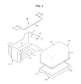
- FIG. 3 is an exploded perspective view of the door guard assembly according to the embodiment of the present invention.
- FIG. 4 is a sectional view of FIG. 2 , cut along line V-V′;
- FIG. 5 is an enlarged view of a section ‘A’ of FIG. 4 ;
- FIG. 6 is an enlarged view of another version of the section ‘A’ shown in FIG. 4 ;
- FIG. 7 is a perspective view showing a part of the door guard assembly according to the embodiment of the present invention.
- FIG. 8 and FIG. 9 are sectional views showing the operational state of a locking bar member of the refrigerator according to the embodiment of the present invention.
- FIG. 10 is a sectional view showing the operational state of the door guard assembly of the refrigerator according to the present embodiment.
- FIG. 1 schematically shows the structure of a refrigerator according to an embodiment of the present invention
- FIG. 2 is a perspective view showing the connection structure of a door guard assembly of the refrigerator.
- the refrigerator includes a main body 10 including a storage chamber 20 , and a door 50 opening and closing the storage chamber 20 .
- the storage chamber 20 is sectioned by a partition 11 into the left and the right of the main body 10 .
- the storage chamber 20 may be sectioned into upper and lower parts, or only one storage chamber 20 may be provided.
- the storage chamber 20 may be used as a refrigerating chamber or a freezing chamber.
- At least one shelf 30 to put food thereon is mounted at an upper part of the storage chamber 20 .
- a drawer-type container 40 to store vegetables and fruit is mounted at a lower part.
- a pair of liners 53 are formed at an inner wall 51 of the door 50 , being extended in a vertical direction at a lateral interval, to mount a plurality of door guards 70 to receive relatively small food or beverage bottles.
- a door guard assembly 100 is formed between the pair of liners 53 disposed at the upper part of the door 50 , to prevent inhabitation of microbes such as mold and germs, and to adjust humidity.
- the door guard assembly 100 includes a door guard 110 mounted to the inner wall 51 of the door 50 opening and closing the storage chamber 20 , and an airtight container 120 which is humidity-adjustable and removably received in the door guard 110 .
- the door guard assembly 100 may be removably mounted to the inner wall 51 of the door 50 .
- locking recesses 111 are formed, being opened downward, on both sides of the door guard 110 while locking projections 60 are formed at the pair of liners 53 to be inserted in the locking recesses 111 .
- FIG. 3 is an exploded perspective view of the door guard assembly of the refrigerator
- FIG. 4 is a sectional view of FIG. 2 , cut along a line V-V′.
- the door guard 110 removably mounted to the inner wall 51 substantially has a box form holding a receiving part 112 to receive the airtight container 120 .
- the receiving part 112 of the door guard 110 may be opened at the top and to one side for convenient insertion and removal of the airtight container 20 .
- At least one cold air inlet hole 114 is formed on a bottom surface 113 of the door guard 110 .
- a mounting depression 115 may be formed in a predetermined depth at the rear side of the bottom surface 113 .
- the cold air inlet hole 114 guides the cold air in the storage chamber 20 to the receiving part 112 of the door guard 110 so that the cold air is supplied to the airtight container 120 .
- the airtight container 120 includes a tray 130 to put the food thereon, and a cover member 140 defining a storage space 121 ( FIG. 4 ) by covering an upper side of the tray 130 so that the food put on the tray 130 is not exposed directly to the external air.
- the storage space 121 is formed by the cover member 140 in this embodiment, embodiments of the present invention are not limited to such a structure.
- the tray 130 may be formed in a shape corresponding to the container 120 so that the storage space 121 is provided within the tray 130 .
- the tray 130 may be made of wood to be capable of adjusting humidity in the storage space 121 to be in a hermetic state.
- the cover member 140 may be formed of a transparent material so that the state of food put on the tray 130 can be checked from the outside.
- the wooden tray 130 may automatically adjust the humidity, accordingly restraining generation and inhabitation of microbes such as mold and germs.
- the wooden tray 130 may effectively prevent deterioration and decay of food being stored for a long time and thereby extend the length of freshness of the food.
- the tray 130 may be teak, iroko, beech, mahogany, oak, ash or maple, each of which, has excellent strength and natural pattern and feel.
- the tray 130 may be formed of other materials.
- the airtight container 120 equipped with the wooden tray 130 may be used as a dairy product storage when mounted in the storage chamber since this element maintains a proper temperature for storage of dairy products such as cheese.
- Leg parts 131 are formed at both lower sides of the tray 130 . As shown in FIG. 4 , the leg parts 131 may be formed in a shape corresponding to the mounting depression 115 of the door guard 110 to be received in the mounting depression 115 when the airtight container 120 is received in the receiving part 112 of the door guard 110 .
- cover member 140 and the tray 130 of the airtight container 120 may prevent entry of the external air into the storage space 121 while achieving a hermetic structure wherein the humidity is adjustable through the wooden tray 130 .
- FIG. 5 is an enlarged view of a section ‘A’ of FIG. 4 .
- FIG. 6 is an enlarged view of another version of the section ‘A’ of FIG. 4 .
- a stepped part 133 is formed near an upper edge of the tray 130 whereas a connection rib 141 is formed along a lower edge of the cover member 140 to be brought into tight contact with the circumference of the stepped part 133 .
- connection rib 141 includes a first tight contact part 143 tightly contacting a first side 134 of the stepped part 133 , and a second tight contact part 145 tightly contacting a second side 135 of the stepped part 133 .
- a gap between the cover member 140 and the tray 130 is airtightly sealed twice by the first and the second tight contact parts 143 and 145 , thereby reducing the possibility of entry of the air into the storage space 121 .
- a packing member 150 having an excellent contacting force may be provided between the cover member 140 and the tray 130 to enhance the airtightness between the cover member 140 and the tray 130 .
- the door guard assembly 100 includes the door guard 110 mounted to the inner wall 51 of the door 50 , and the airtight container 120 received in the door guard 110 .
- the door guard 110 may include the storage space 121 and a wooden bottom surface 113 such that the cover member 140 sealing the storage space 121 is connected to the door guard 110 .
- the door guard 110 may include a separation prevention member to restrain the airtight container 120 from being separated from the door guard 110 by inertia when the door 50 is opened and closed after the airtight container 120 is received in the receiving part 112 of the door guard 110 .
- the separation prevention member may have a locking structure such as a hook structure restricting the airtight container 120 .
- the separation prevention member may include a locking bar member 160 pivotably mounted to the door guard 110 to be automatically lifted and lowered according to movement of the airtight container 120 with respect to the door guard 110 , and a stopping member that restricts the pivoting range of the locking bar member 160 .
- the locking bar member 160 includes a fixed part 161 surrounding a front side 146 of the cover member 140 when the airtight container 120 is inserted in the receiving part 112 of the door guard 110 , supporting parts 163 bent from both ends of the fixed part 161 , and hinge parts 165 formed in a rectangular shape at one end of each of the supporting parts 163 .
- the stopping member may include hinge recesses 171 in which the hinge parts 165 are rotatably inserted.
- the hinge recesses 171 may be formed on a sidewall 116 of the door guard 110 .
- Each of the hinge recesses 171 includes stopping parts that restrict the rotational range of the locking bar member 160 , and more particularly, includes first stopping parts 172 restricting the maximum lifted angle ⁇ of the locking bar member 160 and second stopping parts 173 restricting the maximum lowered angle.
- the first stopping parts 172 are disposed such that the maximum lifted angle ⁇ of the locking bar member 160 becomes about 85°. Accordingly, the locking bar member 160 is lowered by its own weight after being lifted to the maximum position.
- the second stopping parts 173 are disposed such that the maximum lowered angle of the locking bar member 160 becomes about 0°.
- the locking bar member 160 when the airtight container 120 is inserted in the door guard 110 , the locking bar member 160 is disposed at the position (dashed line) corresponding to the maximum lowered angle by its own weight. When the airtight container 120 is separated from the door guard 110 in an arrowed direction in the drawing, the locking bar member 160 is automatically lifted up to the position corresponding to the maximum lifted angle (solid line) along an upper surface 147 of the cover member 140 , thereby releasing the airtight container 120 .
- the door guard assembly 100 may more efficiently maintain freshness of food being stored in the storage space 121 by using the wooden tray 130 capable of adjusting the humidity.
- convenience of insertion and separation of the airtight container 120 may be enhanced by using the locking bar member 160 automatically lifted and lowered according to movements of the airtight container 120 .
- the airtight container 120 is not undesirably separated from the door guard 110 as the door 50 is opening and closing, the operational stability is improved.
- a door guard assembly according to the embodiment of the present invention and a refrigerator having the same may be able to maintain freshness of food being stored in a storage space for a long time, by using a wooden tray which adjusts humidity.
- the door guard assembly improves convenience in putting in food by using a locking bar member that is automatically lifted and lowered according to movements of an airtight container. Furthermore, since the airtight container is not easily separated as the door is opened and closed, the operation stability may be enhanced.
Abstract
Disclosed herein are a door guard assembly and a refrigerator having the same. In the door guard assembly, one side of a storage space of the door guard where food is stored is formed of a wooden material so that humidity of the storage space is adjusted.
Description
- This application claims the benefit of Korean Patent Application. No. 2009-0037286, filed on Apr. 28, 2009 in the Korean Intellectual Property Office, the disclosure of which is incorporated herein by reference.
- 1. Field
- Embodiments of the present invention relate to a refrigerator having a door guard assembly that stores articles such as small-sized food.
- 2. Description of the Related Art
- Generally, a refrigerator is an apparatus that keeps food fresh at a low temperature by supplying cold air to a storage chamber.
- The storage chamber includes a plurality of shelves and containers to receive the food. A door guard is mounted on the inside of a door that opens and closes the storage chamber, to store beverage bottles or cans and other small-size food. The door guard is generally formed of plastic and equipped with a storage space to store the food. Such a storage space may have an open structure, or a half-open structure by having a cover to open and close the storage space.
- However, both the open and the half-open door guards may directly contact the external air and therefore are exposed to risk of germs, and mold. This limits freshness of the food being stored. Furthermore, a dedicated moisture supplying device may additionally be provided to the door guard in order to maintain a proper humidity in the storage space.
- Therefore, it is an aspect of the present invention to provide a door guard assembly having an airtight container capable of adjusting humidity in a storage space, and a refrigerator having the same.
- It is another aspect of the present invention to provide a door guard assembly having excellent convenience and stability in receiving items when mounted to the inside of a door, and a refrigerator having the same.
- Additional aspects of the invention will be set forth in part in the description which follows and, in part, will be apparent from the description, or may be learned by practice of the invention.
- The foregoing and/or aspects of the present invention may be achieved by providing a door guard assembly including a storage chamber, a door that opens and closes the storage chamber, and an airtight container defining a storage space, and the airtight container includes a tray made of a humidity-adjustable material, and a cover member that covers the tray.
- The tray may be made of a wooden material. The wooden material may include at least one of teak, iroko, beech, mahogany, oak, ash and maple. The refrigerator may further include a door guard mounted to an inside of the door so that the airtight container is more stably mounted. The refrigerator may further include a door guard mounted to an inside of the door, and a bottom surface of the door guard may be defined by the tray.
- The door guard may include a separation prevention member restraining separation of the airtight container received in the door guard. The separation prevention member may include a locking bar member which is mounted along an outside of the cover member to be rotated as the airtight container moves from the door guard and is lowered by its own weight, thereby surrounding the cover member as the airtight container is received in the door guard.
- The separation prevention member may include a locking bar member rotatably mounted at the door guard, and stopping members connected to both ends of the locking bar member to restrict a rotational range of the locking bar member.
- Here, each of the stopping members may include a first stopping part restricting the locking bar member at a lifted position thereof, and a second stopping part restricting the locking bar member at a lowered position thereof.
- The tray may include a stepped part, whereas the cover member includes a connection rib engaged in tight contact with the stepped part. A packing member may be provided between the stepped part and the connection rib. The tray may include a leg part disposed at a lower part, whereas the door guard includes a mounting depression formed on a bottom surface thereof.
- The foregoing and/or other aspects of the present invention may also be achieved by providing a door guard assembly including a storage chamber, a door that opens and closes the storage chamber, and an airtight container defining a storage space, wherein the airtight container includes a tray made of a wooden material, and a cover member made of a transparent material to cover the tray.
- The foregoing and/or other aspects of the present invention may also be achieved by providing a door guard assembly including a door guard mounted to an inner wall of a door that opens and closes a storage chamber, and an airtight container received in the door guard and adapted to adjust humidity therein, wherein the airtight container includes a tray made of a wooden material, and a cover member that covers the tray.
- The door guard assembly may further include a locking bar member rotatably mounted to the door guard to surround a front side of the cover member when the airtight container is received in the door guard.
- The locking bar member may include a fixed part surrounding the front side of the cover member, supporting parts bent from both ends of the fixing part, and hinge parts formed at one end of each of the supporting parts.
- The door guard may include hinge recesses connected with the hinge parts, and the hinge recesses each include a first stopping part restricting the maximum lifted angle of the locking bar member so that the locking bar member is lowered by its own weight, and a second stopping part restricting the maximum lowered angle so that the locking bar member fixes the cover member.
- The tray may include a stepped part, the cover member includes a connection rib brought into tight contact with the circumference of the stepped part, and the connection rib includes a first tight contact part tightly contacting a first side of the stepped part and a second tight contact part tightly contacting a second side of the stepped part.
- A packing member may be provided between the stepped part and the connection rib. The cover member may be formed of a transparent material.
- These and/or other aspects of the invention will become apparent and more readily appreciated from the following description of the embodiments, taken in conjunction with the accompanying drawings of which:
-
FIG. 1 is a perspective view briefly showing the structure of a refrigerator according to an embodiment of the present invention; -
FIG. 2 is a perspective view showing the connection structure of a door guard assembly of the refrigerator according to the embodiment of the present invention; -
FIG. 3 is an exploded perspective view of the door guard assembly according to the embodiment of the present invention; -
FIG. 4 is a sectional view ofFIG. 2 , cut along line V-V′; -
FIG. 5 is an enlarged view of a section ‘A’ ofFIG. 4 ; -
FIG. 6 is an enlarged view of another version of the section ‘A’ shown inFIG. 4 ; -
FIG. 7 is a perspective view showing a part of the door guard assembly according to the embodiment of the present invention; -
FIG. 8 andFIG. 9 are sectional views showing the operational state of a locking bar member of the refrigerator according to the embodiment of the present invention; and -
FIG. 10 is a sectional view showing the operational state of the door guard assembly of the refrigerator according to the present embodiment. - Reference will now be made in detail to the embodiment, an example of which is illustrated in the accompanying drawings, wherein like reference numerals refer to the like elements throughout. The embodiment is described below to explain the present invention by referring to the figures.
-
FIG. 1 schematically shows the structure of a refrigerator according to an embodiment of the present invention, andFIG. 2 is a perspective view showing the connection structure of a door guard assembly of the refrigerator. - As shown in
FIG. 1 , the refrigerator includes amain body 10 including astorage chamber 20, and adoor 50 opening and closing thestorage chamber 20. - According to this embodiment, the
storage chamber 20 is sectioned by a partition 11 into the left and the right of themain body 10. However, thestorage chamber 20 may be sectioned into upper and lower parts, or only onestorage chamber 20 may be provided. Thestorage chamber 20 may be used as a refrigerating chamber or a freezing chamber. - At least one
shelf 30 to put food thereon is mounted at an upper part of thestorage chamber 20. A drawer-type container 40 to store vegetables and fruit is mounted at a lower part. - A pair of
liners 53 are formed at aninner wall 51 of thedoor 50, being extended in a vertical direction at a lateral interval, to mount a plurality ofdoor guards 70 to receive relatively small food or beverage bottles. - Additionally, a
door guard assembly 100 is formed between the pair ofliners 53 disposed at the upper part of thedoor 50, to prevent inhabitation of microbes such as mold and germs, and to adjust humidity. - Referring to
FIG. 2 , thedoor guard assembly 100 includes adoor guard 110 mounted to theinner wall 51 of thedoor 50 opening and closing thestorage chamber 20, and anairtight container 120 which is humidity-adjustable and removably received in thedoor guard 110. - The
door guard assembly 100 may be removably mounted to theinner wall 51 of thedoor 50. For this, locking recesses 111 are formed, being opened downward, on both sides of thedoor guard 110 while lockingprojections 60 are formed at the pair ofliners 53 to be inserted in the locking recesses 111. -
FIG. 3 is an exploded perspective view of the door guard assembly of the refrigerator, andFIG. 4 is a sectional view ofFIG. 2 , cut along a line V-V′. - Referring to
FIG. 3 , thedoor guard 110 removably mounted to theinner wall 51 substantially has a box form holding a receivingpart 112 to receive theairtight container 120. - The receiving
part 112 of thedoor guard 110 may be opened at the top and to one side for convenient insertion and removal of theairtight container 20. - At least one cold
air inlet hole 114 is formed on abottom surface 113 of thedoor guard 110. In addition, a mountingdepression 115 may be formed in a predetermined depth at the rear side of thebottom surface 113. - The cold
air inlet hole 114 guides the cold air in thestorage chamber 20 to the receivingpart 112 of thedoor guard 110 so that the cold air is supplied to theairtight container 120. - The
airtight container 120 includes atray 130 to put the food thereon, and acover member 140 defining a storage space 121 (FIG. 4 ) by covering an upper side of thetray 130 so that the food put on thetray 130 is not exposed directly to the external air. - Although the
storage space 121 is formed by thecover member 140 in this embodiment, embodiments of the present invention are not limited to such a structure. For example, thetray 130 may be formed in a shape corresponding to thecontainer 120 so that thestorage space 121 is provided within thetray 130. - The
tray 130 may be made of wood to be capable of adjusting humidity in thestorage space 121 to be in a hermetic state. Thecover member 140 may be formed of a transparent material so that the state of food put on thetray 130 can be checked from the outside. - More specifically, since microfibers of wood contract and expand in accordance with the amount of moisture, the
wooden tray 130 may automatically adjust the humidity, accordingly restraining generation and inhabitation of microbes such as mold and germs. - Also, since wood has antibacterial, disinfectant and air-purifying properties, the
wooden tray 130 may effectively prevent deterioration and decay of food being stored for a long time and thereby extend the length of freshness of the food. - Various wooden materials that are strong enough to not be to affected by the humidity of the
storage chamber 20 may be used for the material of thetray 130. According to the embodiment of the present invention, thetray 130 may be teak, iroko, beech, mahogany, oak, ash or maple, each of which, has excellent strength and natural pattern and feel. - Although wood is used to efficiently adjust the humidity, the
tray 130 according to embodiments of the present invention may be formed of other materials. - The
airtight container 120 equipped with thewooden tray 130 may be used as a dairy product storage when mounted in the storage chamber since this element maintains a proper temperature for storage of dairy products such as cheese. -
Leg parts 131 are formed at both lower sides of thetray 130. As shown inFIG. 4 , theleg parts 131 may be formed in a shape corresponding to the mountingdepression 115 of thedoor guard 110 to be received in the mountingdepression 115 when theairtight container 120 is received in the receivingpart 112 of thedoor guard 110. - According to such a structure, movement of the
tray 130 is restricted while theairtight container 120 is being inserted in the receivingpart 112 of thedoor guard 110. - Furthermore, the
cover member 140 and thetray 130 of theairtight container 120 may prevent entry of the external air into thestorage space 121 while achieving a hermetic structure wherein the humidity is adjustable through thewooden tray 130. -
FIG. 5 is an enlarged view of a section ‘A’ ofFIG. 4 .FIG. 6 is an enlarged view of another version of the section ‘A’ ofFIG. 4 . Referring toFIG. 5 , a steppedpart 133 is formed near an upper edge of thetray 130 whereas aconnection rib 141 is formed along a lower edge of thecover member 140 to be brought into tight contact with the circumference of the steppedpart 133. - The
connection rib 141 includes a firsttight contact part 143 tightly contacting afirst side 134 of the steppedpart 133, and a secondtight contact part 145 tightly contacting a second side 135 of the steppedpart 133. - Therefore, a gap between the
cover member 140 and thetray 130 is airtightly sealed twice by the first and the secondtight contact parts storage space 121. - Additionally, as shown in
FIG. 6 , a packingmember 150 having an excellent contacting force may be provided between thecover member 140 and thetray 130 to enhance the airtightness between thecover member 140 and thetray 130. - As described above, the
door guard assembly 100 according to the embodiment of the present invention includes thedoor guard 110 mounted to theinner wall 51 of thedoor 50, and theairtight container 120 received in thedoor guard 110. However, embodiments of the present invention are not limited to the suggested embodiment. Therefore, for example, thedoor guard 110 may include thestorage space 121 and awooden bottom surface 113 such that thecover member 140 sealing thestorage space 121 is connected to thedoor guard 110. - The
door guard 110 may include a separation prevention member to restrain theairtight container 120 from being separated from thedoor guard 110 by inertia when thedoor 50 is opened and closed after theairtight container 120 is received in the receivingpart 112 of thedoor guard 110. - The separation prevention member may have a locking structure such as a hook structure restricting the
airtight container 120. According to the embodiment, as shown inFIG. 3 , the separation prevention member may include a lockingbar member 160 pivotably mounted to thedoor guard 110 to be automatically lifted and lowered according to movement of theairtight container 120 with respect to thedoor guard 110, and a stopping member that restricts the pivoting range of the lockingbar member 160. - The locking
bar member 160 includes afixed part 161 surrounding afront side 146 of thecover member 140 when theairtight container 120 is inserted in the receivingpart 112 of thedoor guard 110, supportingparts 163 bent from both ends of thefixed part 161, and hingeparts 165 formed in a rectangular shape at one end of each of the supportingparts 163. - The stopping member may include hinge recesses 171 in which the
hinge parts 165 are rotatably inserted. In this embodiment, as shown inFIG. 7 , the hinge recesses 171 may be formed on asidewall 116 of thedoor guard 110. - Each of the hinge recesses 171 includes stopping parts that restrict the rotational range of the locking
bar member 160, and more particularly, includes first stoppingparts 172 restricting the maximum lifted angle α of the lockingbar member 160 and second stoppingparts 173 restricting the maximum lowered angle. - As shown in
FIG. 8 , when thehinge parts 165 of the lockingbar member 160 are lifted within the hinge recesses 171, the upward rotation of thehinge parts 165 is restricted by the first stoppingparts 172. - More particularly, the first stopping
parts 172 are disposed such that the maximum lifted angle α of the lockingbar member 160 becomes about 85°. Accordingly, the lockingbar member 160 is lowered by its own weight after being lifted to the maximum position. - In addition, as shown in
FIG. 9 , when the lockingbar member 160 is lowered, the downward rotation of thehinge parts 165 is restricted by the second stoppingparts 173. For this, the second stoppingparts 173 are disposed such that the maximum lowered angle of the lockingbar member 160 becomes about 0°. - With the above structure, insertion and removal of the
airtight container 120 with respect to thedoor guard 110 may be more conveniently performed since the lockingbar member 160 is automatically lifted and lowered. - As shown in
FIG. 10 , when theairtight container 120 is inserted in thedoor guard 110, the lockingbar member 160 is disposed at the position (dashed line) corresponding to the maximum lowered angle by its own weight. When theairtight container 120 is separated from thedoor guard 110 in an arrowed direction in the drawing, the lockingbar member 160 is automatically lifted up to the position corresponding to the maximum lifted angle (solid line) along anupper surface 147 of thecover member 140, thereby releasing theairtight container 120. - As described above, the
door guard assembly 100 according to the embodiment of the present invention may more efficiently maintain freshness of food being stored in thestorage space 121 by using thewooden tray 130 capable of adjusting the humidity. In addition, convenience of insertion and separation of theairtight container 120 may be enhanced by using the lockingbar member 160 automatically lifted and lowered according to movements of theairtight container 120. Furthermore, since theairtight container 120 is not undesirably separated from thedoor guard 110 as thedoor 50 is opening and closing, the operational stability is improved. - As is apparent from the above description, a door guard assembly according to the embodiment of the present invention and a refrigerator having the same may be able to maintain freshness of food being stored in a storage space for a long time, by using a wooden tray which adjusts humidity.
- In addition, the door guard assembly improves convenience in putting in food by using a locking bar member that is automatically lifted and lowered according to movements of an airtight container. Furthermore, since the airtight container is not easily separated as the door is opened and closed, the operation stability may be enhanced.
- Although an embodiment of the present invention has been shown and described, it would be appreciated by those skilled in the art that changes may be made in this embodiment without departing from the principles and spirit of the invention, the scope of which is defined in the claims and their equivalents.
Claims (20)
1. A refrigerator comprising:
a storage chamber;
a door that opens and closes the storage chamber; and
an airtight container defining a storage space,
wherein the airtight container includes a tray made of a humidity-adjustable material, and a cover member that covers the tray.
2. The refrigerator according to claim 1 , wherein the tray is made of a wooden material.
3. The refrigerator according to claim 2 , wherein the wooden material comprises teak, iroko, beech, mahogany, oak, ash or maple.
4. The refrigerator according to claim 1 , further comprising a door guard mounted to an inside of the door to stably mount the airtight container.
5. The refrigerator according to claim 1 , further comprising:
a door guard mounted to an inside of the door, wherein a bottom surface of the door guard is defined by the tray.
6. The refrigerator according to claim 4 , wherein the door guard includes a separation prevention member restraining separation of the airtight container received in the door guard.
7. The refrigerator according to claim 6 , wherein the separation prevention member comprises a locking bar member which is mounted along an outside of the cover member to be rotated as the airtight container moves from the door guard and is lowered by its own weight thereby surrounding the cover member as the airtight container is received in the door guard.
8. The refrigerator according to claim 6 , wherein the separation prevention member comprises:
a locking bar member rotatably mounted at the door guard; and
stopping members connected to both ends of the locking bar member to restrict a rotational range of the locking bar member.
9. The refrigerator according to claim 8 , wherein each of the stopping members comprises:
a first stopping part restricting the locking bar member when the locking bar member is at a lifted position; and
a second stopping part restricting the locking bar member when the locking bar member is at a lowered position.
10. The refrigerator according to claim 1 , wherein the tray comprises a stepped part and the cover member comprises a connection rib engaged in tight contact with the stepped part.
11. The refrigerator according to claim 10 , further comprising a packing member provided between the stepped part and the connection rib.
12. The refrigerator according to claim 4 , wherein the tray comprises a leg part disposed at a lower part whereas the door guard comprises a mounting depression formed on a bottom surface thereof.
13. A door guard assembly comprising:
a storage chamber;
a door that opens and closes the storage chamber; and
an airtight container holding a storage space,
wherein the airtight container defining a tray made of a wooden material, and a cover member made of a transparent material to cover the tray.
14. A door guard assembly comprising:
a door guard mounted to an inner wall of a door that opens and closes a storage chamber; and
an airtight container received in the door guard and adapted to adjust humidity therein,
wherein the airtight container includes a tray made of a wooden material, and a cover member that covers the tray.
15. The door guard assembly according to claim 14 , further comprising a locking bar member rotatably mounted to the door guard to surround a front side of the cover member when the airtight container is received in the door guard.
16. The door guard assembly according to claim 15 , wherein the locking bar member comprises:
a fixed part surrounding a front side of the cover member;
a plurality of supporting parts bent from both ends of the fixing part; and
a plurality of hinge parts respectively formed at one end of each of the supporting parts.
17. The door guard assembly according to claim 16 , wherein the door guard comprises a plurality of hinge recesses connected with the hinge parts, and the hinge recesses each comprise a first stopping part restricting a maximum lifted angle of the locking bar member so that the locking bar member is lowered by its own weight, and a second stopping part restricting a maximum lowered angle of the locking bar so that the locking bar member fixes the cover member.
18. The door guard assembly according to claim 14 , wherein the tray comprises a stepped part, the cover member comprises a connection rib brought into tight contact with the circumference of the stepped part, and the connection rib comprises a first tight contact part tightly contacting a first side of the stepped part and a second tight contact part tightly contacting a second side of the stepped part.
19. The door guard assembly according to claim 18 , further comprising a packing member provided between the stepped part and the connection rib.
20. The door guard assembly according to claim 14 , wherein the cover member comprises a transparent material.
Applications Claiming Priority (2)
| Application Number | Priority Date | Filing Date | Title |
|---|---|---|---|
| KR10-2009-37286 | 2009-04-28 | ||
| KR1020090037286A KR20100118435A (en) | 2009-04-28 | 2009-04-28 | Door guard assembly and refrigerator having the same |
Publications (1)
| Publication Number | Publication Date |
|---|---|
| US20100270902A1 true US20100270902A1 (en) | 2010-10-28 |
Family
ID=42358696
Family Applications (1)
| Application Number | Title | Priority Date | Filing Date |
|---|---|---|---|
| US12/767,987 Abandoned US20100270902A1 (en) | 2009-04-28 | 2010-04-27 | Door guard assembly and refrigerator having the same |
Country Status (3)
| Country | Link |
|---|---|
| US (1) | US20100270902A1 (en) |
| EP (1) | EP2249108A3 (en) |
| KR (1) | KR20100118435A (en) |
Cited By (19)
| Publication number | Priority date | Publication date | Assignee | Title |
|---|---|---|---|---|
| US20080246381A1 (en) * | 2007-04-04 | 2008-10-09 | Jin Yong Kim | door basket for refrigerator |
| US20090026162A1 (en) * | 2007-07-27 | 2009-01-29 | Lg Electronics Inc. | Can receiving apparatus and refrigerator having the same |
| US20130119845A1 (en) * | 2011-11-15 | 2013-05-16 | Woonkyu Seo | Refrigerator |
| US20130119844A1 (en) * | 2011-11-15 | 2013-05-16 | Woonkyu Seo | Refrigerator |
| US20140035454A1 (en) * | 2012-08-06 | 2014-02-06 | Myeong Suk Kim | Refrigerator |
| US20140312758A1 (en) * | 2011-01-31 | 2014-10-23 | Electrolux Home Products, Inc. | Tilt-out bin and removable crisper |
| US20150198365A1 (en) * | 2014-01-10 | 2015-07-16 | General Electric Company | Door module assembly for a refrigerator appliance |
| US20160095451A1 (en) * | 2014-10-03 | 2016-04-07 | ATA Retail Services, Inc. | Product display tray |
| EP2713123A3 (en) * | 2012-09-27 | 2017-08-30 | Whirlpool EMEA S.p.A | Refrigeration apparatus for food products |
| US9803913B2 (en) * | 2015-04-02 | 2017-10-31 | Whirlpool Corporation | Tiered storage system for refrigerator door |
| US9823012B2 (en) * | 2016-03-28 | 2017-11-21 | Haier Us Appliance Solutions, Inc. | Storage assembly for an appliance |
| US9903641B1 (en) * | 2016-10-27 | 2018-02-27 | Electrolux Home Products, Inc. | Harvest bin assembly |
| US9976797B2 (en) * | 2015-12-10 | 2018-05-22 | Samsung Electronics Co., Ltd. | Refrigerator |
| WO2018205515A1 (en) * | 2017-05-11 | 2018-11-15 | 合肥华凌股份有限公司 | Refrigerator |
| US20180347893A1 (en) * | 2017-06-06 | 2018-12-06 | Whirlpool Corporation | Appliance bin |
| US20180372394A1 (en) * | 2017-06-26 | 2018-12-27 | Samsung Electronics Co., Ltd. | Refrigerator |
| US10168095B2 (en) * | 2016-11-18 | 2019-01-01 | Whirlpool Corporation | Slide out door bin |
| US10458696B1 (en) * | 2018-04-04 | 2019-10-29 | Whirlpool Corporation | Opening system for a storage bin assembly |
| US20190339001A1 (en) * | 2016-04-05 | 2019-11-07 | Lg Electronics Inc. | Refrigerator |
Families Citing this family (1)
| Publication number | Priority date | Publication date | Assignee | Title |
|---|---|---|---|---|
| KR20230131371A (en) | 2022-03-04 | 2023-09-13 | 인포보스 주식회사 | Method, apparatus and program of generation of genome data for analysis, and data structure of genome data for analysis |
Citations (9)
| Publication number | Priority date | Publication date | Assignee | Title |
|---|---|---|---|---|
| US2745260A (en) * | 1953-08-12 | 1956-05-15 | Gen Motors Corp | Hydrator on refrigerator cabinet door |
| US3680941A (en) * | 1971-02-17 | 1972-08-01 | Sears Roebuck & Co | Food storage compartment for refrigerator |
| US3709576A (en) * | 1970-02-26 | 1973-01-09 | Gen Motors Corp | Refrigerator door liners |
| US4706472A (en) * | 1987-02-09 | 1987-11-17 | Howard Margot O | Refrigerated cosmetic storage container |
| US4801182A (en) * | 1987-12-21 | 1989-01-31 | Whirlpool Corporation | Refrigerator door structure |
| US4921315A (en) * | 1987-12-21 | 1990-05-01 | Whirlpool Corporation | Refrigerator door structure |
| US5065885A (en) * | 1990-02-09 | 1991-11-19 | Scaroni F.Lli S.P.A. | Airtight container |
| US5567029A (en) * | 1994-12-22 | 1996-10-22 | Maytag Corporation | Adjustable retainer assembly for a refrigerator door shelf |
| US5951134A (en) * | 1995-04-17 | 1999-09-14 | Whirlpool Corporation | Two piece collar bin |
Family Cites Families (5)
| Publication number | Priority date | Publication date | Assignee | Title |
|---|---|---|---|---|
| DE102004017855A1 (en) * | 2004-04-13 | 2005-11-10 | Liebherr-Hausgeräte Lienz Gmbh | Climate chamber, humidor and method for conditioning a climate chamber |
| US7178343B2 (en) * | 2005-03-23 | 2007-02-20 | Innovative Displayworks, Inc. | Compact thermoelectric wine cooler and humidor |
| JP2007322117A (en) * | 2006-06-02 | 2007-12-13 | Chuichi Boku | In-refrigerator food fresh chamber |
| KR20080094331A (en) * | 2007-04-20 | 2008-10-23 | 엘지전자 주식회사 | A refrigerator |
| US20080277304A1 (en) * | 2007-05-07 | 2008-11-13 | Bending Brook Llc | Container for storing cheese and other temperature sensitive food and items in wine refrigeration units, wine storage rooms and wine cellars |
-
2009
- 2009-04-28 KR KR1020090037286A patent/KR20100118435A/en not_active Application Discontinuation
-
2010
- 2010-04-16 EP EP10160105.2A patent/EP2249108A3/en not_active Withdrawn
- 2010-04-27 US US12/767,987 patent/US20100270902A1/en not_active Abandoned
Patent Citations (9)
| Publication number | Priority date | Publication date | Assignee | Title |
|---|---|---|---|---|
| US2745260A (en) * | 1953-08-12 | 1956-05-15 | Gen Motors Corp | Hydrator on refrigerator cabinet door |
| US3709576A (en) * | 1970-02-26 | 1973-01-09 | Gen Motors Corp | Refrigerator door liners |
| US3680941A (en) * | 1971-02-17 | 1972-08-01 | Sears Roebuck & Co | Food storage compartment for refrigerator |
| US4706472A (en) * | 1987-02-09 | 1987-11-17 | Howard Margot O | Refrigerated cosmetic storage container |
| US4801182A (en) * | 1987-12-21 | 1989-01-31 | Whirlpool Corporation | Refrigerator door structure |
| US4921315A (en) * | 1987-12-21 | 1990-05-01 | Whirlpool Corporation | Refrigerator door structure |
| US5065885A (en) * | 1990-02-09 | 1991-11-19 | Scaroni F.Lli S.P.A. | Airtight container |
| US5567029A (en) * | 1994-12-22 | 1996-10-22 | Maytag Corporation | Adjustable retainer assembly for a refrigerator door shelf |
| US5951134A (en) * | 1995-04-17 | 1999-09-14 | Whirlpool Corporation | Two piece collar bin |
Cited By (39)
| Publication number | Priority date | Publication date | Assignee | Title |
|---|---|---|---|---|
| US8152257B2 (en) * | 2007-04-04 | 2012-04-10 | Lg Electronics Inc. | Door basket for refrigerator |
| US20080246381A1 (en) * | 2007-04-04 | 2008-10-09 | Jin Yong Kim | door basket for refrigerator |
| US20090026162A1 (en) * | 2007-07-27 | 2009-01-29 | Lg Electronics Inc. | Can receiving apparatus and refrigerator having the same |
| US8147016B2 (en) * | 2007-07-27 | 2012-04-03 | Lg Electronics Inc. | Can receiving apparatus and refrigerator having the same |
| US9127878B2 (en) * | 2011-01-31 | 2015-09-08 | Electrolux Home Products, Inc. | Tilt-out bin and removable crisper |
| US20140312758A1 (en) * | 2011-01-31 | 2014-10-23 | Electrolux Home Products, Inc. | Tilt-out bin and removable crisper |
| US20130119845A1 (en) * | 2011-11-15 | 2013-05-16 | Woonkyu Seo | Refrigerator |
| US20130119844A1 (en) * | 2011-11-15 | 2013-05-16 | Woonkyu Seo | Refrigerator |
| US8833882B2 (en) * | 2011-11-15 | 2014-09-16 | Lg Electronics Inc. | Refrigerator |
| US9429355B2 (en) * | 2011-11-15 | 2016-08-30 | Lg Electronics Inc. | Refrigerator |
| US9097457B2 (en) * | 2012-08-06 | 2015-08-04 | Dongbu Daewoo Electronics Corporation | Refrigerator |
| US20140035454A1 (en) * | 2012-08-06 | 2014-02-06 | Myeong Suk Kim | Refrigerator |
| EP2713123A3 (en) * | 2012-09-27 | 2017-08-30 | Whirlpool EMEA S.p.A | Refrigeration apparatus for food products |
| US20150198365A1 (en) * | 2014-01-10 | 2015-07-16 | General Electric Company | Door module assembly for a refrigerator appliance |
| US9513047B2 (en) * | 2014-01-10 | 2016-12-06 | Haier Us Appliance Solutions, Inc. | Door module assembly for a refrigerator appliance |
| US20160095451A1 (en) * | 2014-10-03 | 2016-04-07 | ATA Retail Services, Inc. | Product display tray |
| US9468313B2 (en) * | 2014-10-03 | 2016-10-18 | ATA Retail Services, Inc. | Product display tray |
| US9803913B2 (en) * | 2015-04-02 | 2017-10-31 | Whirlpool Corporation | Tiered storage system for refrigerator door |
| US20180238608A1 (en) * | 2015-12-10 | 2018-08-23 | Samsung Electronics Co., Ltd. | Refrigerator |
| US10458697B2 (en) * | 2015-12-10 | 2019-10-29 | Samsung Electronics Co., Ltd. | Refrigerator |
| US9976797B2 (en) * | 2015-12-10 | 2018-05-22 | Samsung Electronics Co., Ltd. | Refrigerator |
| US9823012B2 (en) * | 2016-03-28 | 2017-11-21 | Haier Us Appliance Solutions, Inc. | Storage assembly for an appliance |
| US10900707B2 (en) * | 2016-04-05 | 2021-01-26 | Lg Electronics Inc. | Refrigerator |
| US20190339001A1 (en) * | 2016-04-05 | 2019-11-07 | Lg Electronics Inc. | Refrigerator |
| US10914508B2 (en) * | 2016-04-05 | 2021-02-09 | Lg Electronics Inc. | Refrigerator |
| US20190339000A1 (en) * | 2016-04-05 | 2019-11-07 | Lg Electronics Inc. | Refrigerator |
| US10151525B2 (en) | 2016-10-27 | 2018-12-11 | Electrolux Home Products, Inc. | Harvest bin assembly |
| US9903641B1 (en) * | 2016-10-27 | 2018-02-27 | Electrolux Home Products, Inc. | Harvest bin assembly |
| US10168095B2 (en) * | 2016-11-18 | 2019-01-01 | Whirlpool Corporation | Slide out door bin |
| US10451333B2 (en) * | 2016-11-18 | 2019-10-22 | Whirlpool Corporation | Slide out door bin |
| WO2018205515A1 (en) * | 2017-05-11 | 2018-11-15 | 合肥华凌股份有限公司 | Refrigerator |
| US20180347893A1 (en) * | 2017-06-06 | 2018-12-06 | Whirlpool Corporation | Appliance bin |
| US10914507B2 (en) * | 2017-06-06 | 2021-02-09 | Whirlpool Corporation | Appliance bin |
| US11892228B2 (en) | 2017-06-06 | 2024-02-06 | Whirlpool Corporation | Appliance bin |
| US10684065B2 (en) * | 2017-06-26 | 2020-06-16 | Samsung Electronics Co., Ltd. | Refrigerator |
| US20200256613A1 (en) * | 2017-06-26 | 2020-08-13 | Samsung Electronics Co., Ltd. | Refrigerator |
| US20180372394A1 (en) * | 2017-06-26 | 2018-12-27 | Samsung Electronics Co., Ltd. | Refrigerator |
| US10941976B2 (en) | 2017-06-26 | 2021-03-09 | Samsung Electronics Co., Ltd. | Refrigerator |
| US10458696B1 (en) * | 2018-04-04 | 2019-10-29 | Whirlpool Corporation | Opening system for a storage bin assembly |
Also Published As
| Publication number | Publication date |
|---|---|
| EP2249108A3 (en) | 2014-08-06 |
| KR20100118435A (en) | 2010-11-05 |
| EP2249108A2 (en) | 2010-11-10 |
Similar Documents
| Publication | Publication Date | Title |
|---|---|---|
| US20100270902A1 (en) | Door guard assembly and refrigerator having the same | |
| KR100887575B1 (en) | Refrigerator with double door | |
| KR102500293B1 (en) | A refrigerator | |
| US10495373B2 (en) | Refrigerator | |
| WO2005079495A2 (en) | Insulated container with access door | |
| KR20060060896A (en) | Kimchi container for kimchi refrigerator | |
| KR101531501B1 (en) | A Vegetable Box for Refrigerator and Refrigerator having the same | |
| JP2012255635A (en) | Refrigerator | |
| US20080251526A1 (en) | Modular storage bin | |
| JP5219935B2 (en) | Freezer refrigerator | |
| US9738425B2 (en) | Refrigerator, refrigerator door, and a refrigerator door bin with a two-piece lid | |
| WO2013106764A1 (en) | Refrigerator | |
| KR100738719B1 (en) | A storing vessel of drawer for Kim-chi refrigerator | |
| KR20200000697U (en) | Storage box | |
| KR101416698B1 (en) | Refrigerator | |
| WO2014109141A1 (en) | Refrigerator | |
| JP7012873B2 (en) | refrigerator | |
| KR200335714Y1 (en) | Wine case for Kimchi refrigerator | |
| US9074807B2 (en) | Reclosable compartment for refrigerator | |
| KR101580161B1 (en) | Container for keeping food | |
| JP2011179726A (en) | Refrigerator | |
| KR100828048B1 (en) | Refrigerator having home-bar | |
| KR100535830B1 (en) | Refrigerator equiped with door-guard having transparent window | |
| CN116265843A (en) | Door storage unit for refrigerator and refrigerator | |
| EP1916491B1 (en) | Refrigerator shelf, and refrigerator equipped with such a shelf |
Legal Events
| Date | Code | Title | Description |
|---|---|---|---|
| AS | Assignment |
Owner name: SAMSUNG ELECTRONICS CO., LTD., KOREA, REPUBLIC OF Free format text: ASSIGNMENT OF ASSIGNORS INTEREST;ASSIGNORS:KIM, PO CHEON;JUNG, SANG GYU;KIM, CHANG YONG;REEL/FRAME:024295/0611 Effective date: 20100425 |
|
| STCB | Information on status: application discontinuation |
Free format text: ABANDONED -- FAILURE TO RESPOND TO AN OFFICE ACTION |