US20110034883A1 - Sealing Between a Cannula Part and a Fluid Path - Google Patents
Sealing Between a Cannula Part and a Fluid Path Download PDFInfo
- Publication number
- US20110034883A1 US20110034883A1 US12/865,566 US86556609A US2011034883A1 US 20110034883 A1 US20110034883 A1 US 20110034883A1 US 86556609 A US86556609 A US 86556609A US 2011034883 A1 US2011034883 A1 US 2011034883A1
- Authority
- US
- United States
- Prior art keywords
- cannula
- opening
- sealing
- fluid path
- cannula part
- Prior art date
- Legal status (The legal status is an assumption and is not a legal conclusion. Google has not performed a legal analysis and makes no representation as to the accuracy of the status listed.)
- Granted
Links
Images


Classifications
-
- A—HUMAN NECESSITIES
- A61—MEDICAL OR VETERINARY SCIENCE; HYGIENE
- A61M—DEVICES FOR INTRODUCING MEDIA INTO, OR ONTO, THE BODY; DEVICES FOR TRANSDUCING BODY MEDIA OR FOR TAKING MEDIA FROM THE BODY; DEVICES FOR PRODUCING OR ENDING SLEEP OR STUPOR
- A61M5/00—Devices for bringing media into the body in a subcutaneous, intra-vascular or intramuscular way; Accessories therefor, e.g. filling or cleaning devices, arm-rests
- A61M5/14—Infusion devices, e.g. infusing by gravity; Blood infusion; Accessories therefor
- A61M5/158—Needles for infusions; Accessories therefor, e.g. for inserting infusion needles, or for holding them on the body
-
- A—HUMAN NECESSITIES
- A61—MEDICAL OR VETERINARY SCIENCE; HYGIENE
- A61M—DEVICES FOR INTRODUCING MEDIA INTO, OR ONTO, THE BODY; DEVICES FOR TRANSDUCING BODY MEDIA OR FOR TAKING MEDIA FROM THE BODY; DEVICES FOR PRODUCING OR ENDING SLEEP OR STUPOR
- A61M5/00—Devices for bringing media into the body in a subcutaneous, intra-vascular or intramuscular way; Accessories therefor, e.g. filling or cleaning devices, arm-rests
- A61M5/14—Infusion devices, e.g. infusing by gravity; Blood infusion; Accessories therefor
- A61M5/142—Pressure infusion, e.g. using pumps
- A61M5/14244—Pressure infusion, e.g. using pumps adapted to be carried by the patient, e.g. portable on the body
- A61M5/14248—Pressure infusion, e.g. using pumps adapted to be carried by the patient, e.g. portable on the body of the skin patch type
- A61M2005/14252—Pressure infusion, e.g. using pumps adapted to be carried by the patient, e.g. portable on the body of the skin patch type with needle insertion means
-
- A—HUMAN NECESSITIES
- A61—MEDICAL OR VETERINARY SCIENCE; HYGIENE
- A61M—DEVICES FOR INTRODUCING MEDIA INTO, OR ONTO, THE BODY; DEVICES FOR TRANSDUCING BODY MEDIA OR FOR TAKING MEDIA FROM THE BODY; DEVICES FOR PRODUCING OR ENDING SLEEP OR STUPOR
- A61M5/00—Devices for bringing media into the body in a subcutaneous, intra-vascular or intramuscular way; Accessories therefor, e.g. filling or cleaning devices, arm-rests
- A61M5/14—Infusion devices, e.g. infusing by gravity; Blood infusion; Accessories therefor
- A61M5/158—Needles for infusions; Accessories therefor, e.g. for inserting infusion needles, or for holding them on the body
- A61M2005/1581—Right-angle needle-type devices
-
- A—HUMAN NECESSITIES
- A61—MEDICAL OR VETERINARY SCIENCE; HYGIENE
- A61M—DEVICES FOR INTRODUCING MEDIA INTO, OR ONTO, THE BODY; DEVICES FOR TRANSDUCING BODY MEDIA OR FOR TAKING MEDIA FROM THE BODY; DEVICES FOR PRODUCING OR ENDING SLEEP OR STUPOR
- A61M5/00—Devices for bringing media into the body in a subcutaneous, intra-vascular or intramuscular way; Accessories therefor, e.g. filling or cleaning devices, arm-rests
- A61M5/14—Infusion devices, e.g. infusing by gravity; Blood infusion; Accessories therefor
- A61M5/158—Needles for infusions; Accessories therefor, e.g. for inserting infusion needles, or for holding them on the body
- A61M2005/1585—Needle inserters
-
- A—HUMAN NECESSITIES
- A61—MEDICAL OR VETERINARY SCIENCE; HYGIENE
- A61M—DEVICES FOR INTRODUCING MEDIA INTO, OR ONTO, THE BODY; DEVICES FOR TRANSDUCING BODY MEDIA OR FOR TAKING MEDIA FROM THE BODY; DEVICES FOR PRODUCING OR ENDING SLEEP OR STUPOR
- A61M5/00—Devices for bringing media into the body in a subcutaneous, intra-vascular or intramuscular way; Accessories therefor, e.g. filling or cleaning devices, arm-rests
- A61M5/14—Infusion devices, e.g. infusing by gravity; Blood infusion; Accessories therefor
- A61M5/158—Needles for infusions; Accessories therefor, e.g. for inserting infusion needles, or for holding them on the body
- A61M2005/1587—Needles for infusions; Accessories therefor, e.g. for inserting infusion needles, or for holding them on the body suitable for being connected to an infusion line after insertion into a patient
-
- A—HUMAN NECESSITIES
- A61—MEDICAL OR VETERINARY SCIENCE; HYGIENE
- A61M—DEVICES FOR INTRODUCING MEDIA INTO, OR ONTO, THE BODY; DEVICES FOR TRANSDUCING BODY MEDIA OR FOR TAKING MEDIA FROM THE BODY; DEVICES FOR PRODUCING OR ENDING SLEEP OR STUPOR
- A61M39/00—Tubes, tube connectors, tube couplings, valves, access sites or the like, specially adapted for medical use
- A61M39/22—Valves or arrangement of valves
- A61M39/26—Valves closing automatically on disconnecting the line and opening on reconnection thereof
- A61M2039/267—Valves closing automatically on disconnecting the line and opening on reconnection thereof having a sealing sleeve around a tubular or solid stem portion of the connector
-
- A—HUMAN NECESSITIES
- A61—MEDICAL OR VETERINARY SCIENCE; HYGIENE
- A61M—DEVICES FOR INTRODUCING MEDIA INTO, OR ONTO, THE BODY; DEVICES FOR TRANSDUCING BODY MEDIA OR FOR TAKING MEDIA FROM THE BODY; DEVICES FOR PRODUCING OR ENDING SLEEP OR STUPOR
- A61M5/00—Devices for bringing media into the body in a subcutaneous, intra-vascular or intramuscular way; Accessories therefor, e.g. filling or cleaning devices, arm-rests
- A61M5/14—Infusion devices, e.g. infusing by gravity; Blood infusion; Accessories therefor
- A61M5/1413—Modular systems comprising interconnecting elements
Definitions
- the invention relates to an infusion part comprising a cannula part and a fluid path for providing continuous administration of a therapeutically working substance, such as insulin.
- the infusion part can be connected to delivery means which means provide e.g. controlled dosage of medication or nutrients.
- WO 2007/071258 describes a medical device for delivering fluid comprising an injection part and a fluid delivery part where the fluid delivery part and the injection part can be separated and rejoined.
- the fluid delivery part comprises a reservoir, means for transport of liquid e.g. in form of a pump and a house in which the active units of the delivery part is placed.
- the injection part comprises: a base plate, a cannula part comprising a body with a through going opening provided with a cannula extending past the proximal side of the base plate and means for fixation of the base plate to the skin of the user e.g. in the form of a mounting pad.
- the cannula part is provided with one or more openings leading fluid to a hollow in the cannula part and each opening is covered with a self closing membrane.
- the delivery part and the injection part is assembled through a connector comprising a fluid path leading fluid from the reservoir to the through-going opening in the cannula part which fluid path comprises means for blocking access to the injection part when the connector is disconnected from the delivery part and/or the injection part.
- EP 652 027 discloses an infusion device to be placed on a patients skin for delivering of medication.
- This infusion device comprises a cannula device ( 10 ) carrying a penetrating cannula of steel.
- the cannula device ( 10 ) is concentric i.e. all parts of the cannula device are rotational symmetric with respect to rotation around the common axis.
- the cannula device ( 10 ) can slide axially and has a channel ( 11 ) with an inlet opening in the cylindrical side surface which inlet opening corresponds to an outlet opening of a channel ( 7 ) through which medication or the like is entering.
- Above and below the outlet of the channel ( 7 ) is placed a first and a second O-ring ( 8 ).
- Both O-rings ( 8 ) are placed in circular grooves in the inner surface of the surrounding the house ( 1 ).
- the inserter and the cannula device are permanently joined together and this allows the cannula device to be at least partly inserted into a cannula opening which fits tightly around the cannula device even before insertion of the cannula device has taken place i.e. this results in that there are friction between the cannula part and the inner surface of the house during the entire insertion procedure. Also there is no teaching in this document of how to adapt the use of a soft cannula to this device.
- the object of the invention is to provide an infusion part allowing the use of a soft cannula which is safe and simple to manufacture and which reduces the friction between the cannula part and the base part and therefore also the risk of incorrect positioning of the cannula part during insertion.
- This object is achieved by reducing the time where both the moving cannula part and the inner surface of the opening for receiving the cannula part are in contact with the gasket sealing of fluid from the surroundings. This can generally be achieved by creating a cannula part having an increasing diameter or by creating a sealing with a smaller area.
- an infusion part as described in claim 1 comprising a cannula part and a fluid path, where
- the sealing is surrounding the inlet/outlet opening and/or the distance d 1 between a centre line c of the cannula part and a point on the outer surface of the cannula part positioned at or above the upper edge of the sealing is larger than the distance d 2 between the centre line c of the cannula part and a point on the outer surface of the cannula part positioned at or below the lower edge of the sealing.
- “Upper edge of the sealing” defines the part of the sealing or gasket which has the longest distance to the patient's skin
- “lower edge of the sealing” defines the part of the sealing which has the shortest distance to the patient's skin when the infusion part according to the invention is inserted in a use position.
- the body of the cannula part is provided with a sealing before use or alternatively the opening of the fluid path or the surface surrounding the opening of the fluid path is provided with a sealing before use.
- “Provided” means that the sealing or gasket is somehow attached to the indicated surface, it might just be placed in a groove or a cavity as indicated in FIG. 9 or 10 .
- the penetrating member is provided with attachment means assuring that the penetrating member is unreleasably attached to the base part after insertion.
- the body of the cannula part is provided with a sealing or gasket placed along the edge of the opening through which fluid enters or exits the cannula part.
- the opening of the fluid path corresponding to an opening of the cannula part is provided with a sealing placed along the edge of the opening i.e. in a short distance from the opening.
- a short distance is understood to be less than or equal to the distance equaling the diameter of the opening and if the opening is not round: less than or equal to the longest dimension of the opening.
- the sealing material according to any embodiment can be hydrophobic and elastic e.g. the sealing material is made of silicone.
- the body of the cannula part has at least one second opening to the inner through going opening and preferably this at least one second opening to the inner through going opening is covered by a self closing membrane which membrane can be penetrated by a blunt or pointy needle and can be made of silicone.
- This at least second opening can e.g. be used for insertion of the device if the cannula is a soft cannula not able to cut its way through the patients skin, then a separate insertion needle can pass through the second opening, all through the cannula and provide a cutting edge in front of the cannula. It can also be used for supplying medication or nutrients which only are given to the patient in smaller doses a few times a day.
- the infusion part comprises a base part which can be fastened to a patient's skin.
- the base part is provided with an opening corresponding to the profile at the non-penetrating end of the cannula part.
- the “non-penetrating end” of the cannula part is the end opposite the cannula i.e. the distal end of the penetrating member where “distal” indicates the end is turned away from the patient.
- the cannula part has a flat surface part on one side corresponding to a flat wall surrounding the opening of the fluid path, i.e. that the opening is “adapted” means that the surrounding walls correspond to the cannula part and assures that the cannula part ends up in a well-defined and close fitted—preferably press-fitted—position. “Press-fitted” means that it is so close fitted that it requires a force to insert the cannula part.
- the opening can extend below the outer surface of the base part providing walls which tightly fits around the cannula part when the cannula part is inserted into the patient and preferably the inlet or outlet opening of the fluid path opens into the wall of the opening fitting around the cannula part and when the cannula part is inserted, an inlet or outlet to the inner opening of the cannula part corresponds to the inlet/outlet opening of the fluid path.
- the distance d 1 between a centre line c of the cannula part and a point on the outer surface of the cannula part positioned at the upper edge of the sealing ( 18 ) is larger than the distance d 2 between the centre line c of the cannula part and a point on the outer surface of the cannula part positioned at the lower edge of the sealing.
- the centre line c is parallel to the direction of insertion.
- the angle d is the angle between the direction of insertion of the cannula part and a plane being tangent to the surface surrounding the opening opposite the sealing, and 0 ⁇ d ⁇ 90°, normally 45 ⁇ d ⁇ 80° and most often 70 ⁇ d ⁇ 80°.
- the base part is formed at least partly of a hard material. That a material is “hard” means that it can not be penetrated by a needle, and also that it is able to maintain a shape it is given during production although it might be possible to flex the material due to the shape it is given e.g. if it is formed as a thin plate or if it is very long but it will not be possible to compress it i.e. reduce it size.
- the fluid path is formed as an integrated part of the base part fastened to the patient's skin. That the fluid path is formed as an integrated part means that it is an unreleasable part of the device, i.e. it is permanently attached to the device at some time during the manufacturing process of the base part and when the base part is in use it will not be possible to separate the fluid path and the rest of the base part.
- the hard material is a molded plastic material e.g. the plastic material is polypropylene.
- the base part comprises fastening means for attaching delivery means to the base part.
- the delivery means can comprise a connecting part provided with means corresponding to the means for fastening of delivery means and provided with a tube for transferring medication to the infusion part or the delivery means can comprise a reservoir containing medication and means for transferring medication to the infusion part.
- the means for transferring will normally be a pump and a programmable part possibly combined with a sensor for assuring appropriate amounts of medication to be delivered to the patient.
- FIG. 1 shows a first embodiment of an infusion part according to the invention.
- FIGS. 2 and 2A shows a second embodiment of an infusion part according to the invention.
- FIG. 3 shows the same embodiment of an infusion part as FIGS. 2 and 2A .
- FIGS. 4A , 4 B and 4 C show a cannula part which can be used in connection with the invention.
- FIG. 5 shows a front view of an inserter which can be used in connection with the invention.
- FIG. 6 shows a view from the proximal side of the inserter of FIG. 5 .
- FIG. 7 shows a connector part which can be part of an infusion part according to the invention.
- FIG. 8 shows the same connector part as FIG. 7 without the bubble membrane covering the inlet.
- FIGS. 9A and 9B show a cannula part having an inclined contact surface.
- FIG. 10A-10D show an enlargement of the contact between the cannula part and the cannula opening of the connection part.
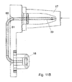
- FIGS. 11A , B and C show an embodiment of a base part provided with a fluid path mainly constructed of a tube.
- FIG. 13 shows a cannula part which can be used in connection with the invention.
- FIG. 1 shows an embodiment of an infusion part comprising a cannula part and a fluid path according to the invention.
- This embodiment comprises a surface plate 1 attached to a contact surface.
- the surface plate 1 is in this embodiment constructed of a molded plastic material and the contact surface can be the proximal side of a mounting pad 2 which mounting pad 2 is unreleasably fastened to the surface plate 1 during manufacturing of the device.
- the mounting pad 2 of this embodiment has the same area as the surface plate 1 but it could be of an area larger or smaller than the surface plate 1 .
- a connector part 3 is position on the surface plate 1 .
- the connector part 3 provides for the contact between the base part and some kind of delivery means.
- the surface plate 1 and at least an outer cover of the connector part 3 is simply molded in one piece during manufacturing of the device.
- the internal parts of the connector part 3 forms a fluid path between e.g. a reservoir of medication or a reservoir for liquid collected from the patient and a cannula part 7 . Therefore the connector part 3 is provided with at least two openings, one opening at each end of the fluid path where the first opening 13 is an inlet or outlet opening receiving or delivering fluid to a not shown reservoir and the second opening is an inlet or outlet opening 12 receiving or delivering fluid to a cannula part 7 .
- the connection part 3 might be provided with extra openings e.g. for inserting the cannula part, for injection of a second medication or nutrient or for letting the fluid in the fluid path get in contact with a sensor.
- first opening 13 will be referred to as “inlet” and the second opening will be referred to as “outlet” although the direction of the flow through the fluid path is not significant for the invention.
- FIG. 1 is provided with two guiding means 4 in the form of two right angled L-shaped profiles in the form: ⁇ ⁇ , which profiles are protruding from the surface plate 1 of a base part having a lower or proximal side which is fastened to the skin of the patient.
- the guiding means 4 correspond to guiding means on a delivery part or a cover or connecting means which are to be fastened to the base part during use.
- Such corresponding means can e.g. be formed as one or more hooks having an L-shaped profile in the form: ⁇ and ⁇ corresponding to the profiles on the base part.
- connection part 3 of this embodiment is very short and the inlet 13 of the connection part 3 is placed in a centre position in relation to the guiding means 4 .
- the top of an inserted cannula part 7 is shown inserted into the connection part 3 .
- connection part 3 is further provided with a cannula cavity 12 A which accurately fits around a cannula part 7 i.e. the cannula cavity 12 A has the same 3-dimensional shape or profile as the cannula part 7 and is just big enough to let the cannula part 7 pass through and then fit into the opening.
- the cannula part 7 is shown in a position where the cannula part 7 is fully inserted.
- the upper surface i.e. the distal surface of the cannula part 7 is normally at level with or at a lower level than the outer surface of the connection part 3 around the cannula cavity 12 A.
- an opening 20 in a side surface of a body 24 of the cannula part 7 corresponds to the opening 12 of the fluid path of the connection part 3 and fluid can flow from one part to the other.
- the opening 12 might in the following be referred to as an “outlet” although the direction of the flow is not significant to the invention.
- FIGS. 2 and 3 show a second embodiment of an infusion part according to the invention.
- a delivery part corresponding to this embodiment could be joined to the base part by pushing the delivery part down toward the guiding means 4 which in this case is a longitudinal raised platform having a magnet 5 fastened to the top surface.
- the delivery part would be provided with a corresponding magnet e.g. of a smaller or different size than the magnet 5 which is placed in such a way e.g. in a track corresponding to the raised platform 4 , that the corresponding magnet of the delivery part can slide along the magnet 5 on the raised platform 4 of the base part in the longitudinal direction.
- two release handles can engage respectively with two protruding parts 15 protruding from the upper surface of the surface plate 1 .
- FIGS. 2 and 2A the base part is shown without the cannula part 7 and in FIG. 3 the base part is shown having the cannula part 7 in a positioned reached just before insertion of the cannula part 7 , normally the cannula part 7 would at this stage of insertion still be placed inside an inserter and it would not be visible.
- FIGS. 5 and 6 shows the direction the handle 11 has to be pushed in, in order to initiate insertion of the cannula part 7 .
- a not shown insertion needle can be retracted to the inside of the inserter 10 and the inserter 10 is removed from the base part, leaving an inserted cannula 22 fastened to the surface plate 1 . If the cannula 22 of the cannula part 7 is a hard self penetrating cannula there will be no separate insertion needle and therefore no need to retract the insertion needle.
- connection part 3 is shown with an outer cover provided by the molded surface plate 1 .
- the outer cover shown in this embodiment is not an independent unit but is attached unreleasably to or simply made as a part of the surface plate 1 e.g. by a molding process.
- the outer cover is provided with a cannula cavity 12 A for the cannula part 7 and an access opening 13 for e.g. a reservoir thereby allowing access to the fluid path of the connection part 3 by the reservoir and the cannula part 7 .
- the cannula cavity 12 A allows the cannula part 7 to be inserted sub- or transcutaneous into the patient within the circumference of the hard surface plate 1 and the contact surface 2 of the base part which in this embodiment is provided by a mounting pad is also provided with an opening 12 B which allows for the cannula to be inserted (see FIGS. 7 and 8 ).
- This opening 12 B is not necessary if the contact surface 2 is constructed of such a material and thickness that it can be penetrated by at least the cannula 22 of the cannula part 7 .
- connection part 3 is shown without the outer cover provided by the molded surface plate 1 .
- the outlet opening 12 of the connection part 3 is provided with an elastic sealing 18 around the outlet opening 12 .
- the cannula part 7 When the cannula part 7 is inserted it will be press fitted into the cannula opening 12 and the elastic sealing 18 will provide a completely fluid tight gasket around the corresponding openings 12 and 20 .
- the cannula cavity 12 A can be provided with a decreasing cross-section in a plane parallel to the cannula 22 when inserted and perpendicular to the surface where the outlet of the fluid path is positioned.
- the cannula part 7 will have a corresponding decreasing cross-section.
- a bubble shaped membrane 17 has been positioned around the first opening 13 .
- the membrane 17 completely covers the inlet opening 13 and prevents contamination of the internal of the connection part 3 .
- a connector needle 19 will penetrate the membrane 17 and provide a completely fluid tight transfer of fluid between the connection part 3 and the reservoir.
- That the membrane 17 is bubble shaped means that it is attached around the opening—normally around the edge of the opening—it protects and the membrane 17 protrudes from the planed formed by the edge of the opening and forms a dome in a distance from the edge which distance normally corresponds to the length of a connector needle 19 .
- connection needle 19 is shown as being a part of the connection part 3 i.e. it is attached to the connection part 3 but it might just as well be a part of the reservoir.
- connection part 3 is provided with both a connector needle 19 and a bubble shaped self closing membrane 17 and the reservoir is also provided with a bubble shaped self closing membrane.
- both parts are provided with self closing membranes it will be possible to separate the two units from each other and rejoin them at a later time without the internal fluid path of the connection part 3 and thereby the patient being contaminated.
- FIGS. 4A , 4 B and 4 C shows an enlargement of a cannula part 7 which can be used in connection with the invention.
- This embodiment comprises a body 24 provided with a cannula 22 and with a protruding front 25 having a flat surface.
- the surface of the cannula part 7 having an opening need not be flat; it can actually have any desired shape as long as it is possible to create a corresponding surface on the connection part 3 facing the cannula part 7 .
- the front 25 is inclined in such a way that the cross-section at the upper i.e. distal end is larger than the cross-section at the proximal end, i.e. the enc closest to the patient after insertion, of the front in at least one dimension.
- the front 25 is provided with an opening 20 through which liquid can exit or enter the cannula part 7 .
- the body 24 is further provided with a top opening 21 which opening can be covered with a self closing membrane.
- the opening 21 need some kind of entrance protection as it is facing an outer surface which is in contact with the surroundings.
- the top opening 21 is primarily used when inserting the cannula part 7 if the cannula 22 is a soft cannula.
- the cannula 22 is soft means that is made of a relatively soft material which can not penetrate the patients skin, in this case it is necessary to use a pointy insertion needle of a relatively hard material when inserting the cannula and this pointy needle can be inserted through the top opening 21 , pass through an inner through going opening in the body 24 of the cannula part and further pass through the full length of the cannula 22 in such a way that the pointy end of the insertion needle stick out of the open end of the hollow cannula 22 .
- the insertion needle is retracted and the cannula 22 is left inside the patient.
- the cannula part 7 is also provided with fastening means 23 which fastening means 23 lock the cannula part 7 to the base part at the time where it is fully inserted.
- the fastening means 23 of this embodiment comprises outward hooks that can pivot around an axe close to the body 24 of the cannula part 7 in such a way that the diameter formed by the outermost edge of the hooks can be reduced when the hooks are pressed inward i.e. towards the centre of the cannula part 7 .
- the hooks will return to their original position due to the flexibility of the material.
- the hooks will be pushed inwards when they pass an opening such as e.g.
- FIGS. 5 and 6 show an inserter that can be used to position the cannula part 7 in the base part.
- the inserter comprises a housing 10 provided with an internal opening where the cannula part 7 can be moved from a retracted position to a forward position. In the retracted position the cannula 22 is not in contact with the patient and in the forward position the cannula 22 is inserted into the patient.
- the inserter further comprises an actuator handle 11 which is to be activated when the cannula part 7 is to be inserted and it comprises fastening means 14 which means can lock the inserter to the base part before and during insertion.
- the inserter should be fastened to the base part under sterile conditions or the joined base part and inserter should be sterilized after fastening of the inserter in order to prevent contamination of the cannula cavity 12 A, and in order to reduce the amount of material placed on the patient's skin it is desirable to be able to remove the whole of or at least part of the inserter after the cannula part 7 has been inserted.
- FIGS. 9A and 9B show an enlargement of a second embodiment of a cannula part 7 .
- FIG. 9A shows the cannula part 7 in a state just before insertion and
- FIG. 9B shows the cannula part 7 inserted into the cavity 12 A in the base part.
- This embodiment also comprises a body 24 provided with a cannula 22 and with a protruding part 25 having a flat surface provided with an opening 20 .
- the protruding part 25 is inclined in such a way that the pressure between the opening 20 and the sealing 18 around the second opening 12 of the connection part 3 is increased, also the sealing 18 is subjected to less tear during insertion.
- the inclination of the inclined part 25 is defined by the angle d between the centre line c of the cannula 22 (the centre line c is parallel to the insertion direction) and a line parallel to the surface around the opening 20 . If the surface around the opening 20 is not straight, then the line parallel to the surface would be the tangent to the surface around the opening 20 .
- the angle d will be larger than 0° and smaller than or equal to 90°, normally d ⁇ ]0°, 30°] depending on the diameter or the protrusion of the sealing 18 or [60°, 90°[.
- the distance d 1 measured at the distal end of the surface of the protruding inclined part 25 where the distal end is the end of the cannula part 7 which is furthest away from the patient after insertion, between the surface of the protruding inclined part 25 and the centre c of the cannula part 7 is larger than the distance d 2 between the surface of the protruding part 25 at the proximal end i.e. the end closest to the patient after insertion, and the centre c of the cannula part 7 .
- the distance d 2 will be so small that the proximal end of the protruding inclined part 25 does not touch the sealing 18 of the connection part 3 during insertion.
- d 0° as the protruding part 25 and the centre line c are parallel.
- the cannula part 7 will be in sliding contact with the protruding sealing 18 which can cause the sealing to be distorted.
- the protruding front 25 of the cannula part 7 need not be flat; it can actually have any desired shape e.g. partly spherical as long as it is possible to create a corresponding surface on the connection part 3 facing the cannula part 7 .
- the opening 20 of the protruding front 25 can behave as an inlet or an outlet depending on the purpose of the cannula part 7 .
- FIGS. 9A and 9B which is a cut-through view it is shown how the top opening 21 of the body 24 is covered with a self closing membrane 21 A. As according to the embodiment of FIG.
- the top opening 21 is primarily used when inserting the cannula part 7 if the cannula 22 is a soft cannula but the top opening 21 can also be used to inject medication or nutrients other than the primary medication which could be e.g. insulin which the patient receive via the opening 20 .
- This embodiment of the cannula part 7 is also provided with fastening means 23 and in this embodiment the fastening means 23 has the form of a protruding part 23 on the cannula part 7 which corresponds to a flexible part 23 A on the stationary base part.
- the flexible part 23 A can be pushed outward as indicated with an arrow at FIG. 9A when the protruding part 23 on the cannula part 7 passes during insertion of the cannula part 7 .
- the upward surface of the protruding part 23 of the cannula part 7 will be locked by the downward surface of the flexible part 23 A of the base part and it will not be possible to detach the cannula part 7 from the base part.
- the cannula part 7 of FIGS. 9A and 9B is provided with a soft cannula 22 which soft cannula 22 together with a bushing 29 provides a cannula assembly.
- This assembly is normally fastened inside the body 24 of the cannula part 7 by an interference fit i.e. it is only the friction between the body 24 and the cannula assembly which keeps it in the correct position.
- the body 24 of the cannula part 7 can be provided with a ring shaped recess encircling the exit for the soft cannula 22 .
- the soft cannula 22 can form a small bulk i.e. a ring shaped bulk which prevents the soft cannula from sliding back.
- FIG. 10 illustrates how the unrestricted openings between the cannula part 7 having the body 24 and the fluid path having the inlet/outlet opening 12 slide into place.
- the body 24 of the cannula part 7 is provided with an inclined edge in order to reduce distortion or tearing of the sealing.
- the shown sealing 18 is a circular or cylindrical silicone unit which is placed in a round track around the inlet/outlet opening 12 in the connection part 3 .
- the wall where the sealing or gasket 18 has been placed is provided with an adjacent expansion room 28 .
- the sealing 18 can occupy this room.
- the whole cylindrical sealing part 18 is angled in order to allow uniform sealing deformation.
- the cylindrical sealing 18 does not form the walls of the inlet/outlet opening 12 , the wall or surfaces of this opening is formed by the material which the connection part 3 is formed of in order to provide a pipe which cannot be deformed.
- the sealing face can be provided with a small continuous protrusion protruding from the sealing face and having the same shape as the sealing which would e.g. be circular if the sealing has the cylindrical shape shown in FIG. 10A-D .
- FIGS. 11A-11C show one embodiment of a connection part 3 .
- FIG. 11A show the embodiment of the connection part 3 in an exploded view where the internal holding parts 61 for a tube 60 providing a fluid path is shown.
- FIG. 11B shows a cut through the internal holding part 61 according to which it is possible to the position of the tube 60 .
- FIG. 11C shows an enlargement of the encircled part of FIG. 11A .
- connection part 3 and the surface plate 1 is molded in one piece of a plastic material, the connection part is provided with several openings, one opening is the cavity 12 A which is prepared for fitting in the cannula part 7 and another opening is prepared for fitting in the internal parts of the connection part 3 .
- the internal parts of the connection part 3 according to this embodiment comprises one tube which at two positions are bend in 90° i.e. both the inlet and the outlet end of the tube 60 points in the same direction perpendicular to the connecting part of the tube 60 where the connecting part of the tube 60 forms the fluid path between the two bending parts.
- the tube 60 is protected by a bubble shaped membrane 17 and at the other end the tube 60 is open and unprotected, but the open tube end is surrounded by a sealing 18 which is attached unreleasably to a holding part 61 .
- a cover 62 accurately fitting in the opening is placed in level with the surface of the connection part 3 in such a way that the user experience a smooth surface which cannot be tampered with.
- the embodiment of the base part shown in FIG. 11A is provided with guiding means 26 placed inside the cavity 12 A of the connection part 3 .
- the two opposing ribs 26 which constitute the guiding means correspond to closely fitting openings 27 in the cannula part 7 .
- the guiding means 26 and the corresponding parts 27 on the cannula part can have other forms, the important feature is that they correspond to each other and make it possible for the cannula part 7 to slide into use position.
- FIG. 11B shows an enlargement of the internal parts of the connection part 3 .
- the holding parts 61 comprise a single molded part which is providing a stable embedment of the tube 60 .
- the open end of the tube 60 opens into a space surrounded by the sealing 18 .
- the closed end of the tube 60 is completely surrounded by a soft membrane. “Completely surrounded” means that the there is no free access to the surroundings, “soft membrane” means that the membrane can be penetrated by a needle, especially the connector needle 19 which is provided by the end of the tube 60 and which is embedded inside the soft membrane.
- the end of the tube 60 which constitutes the connector needle 19 is in this embodiment not actually in touch with the surrounding membrane 17 .
- the connector needle 19 is surrounded by air, and the internal space surrounding the connector needle 19 has a cylindrical or conical shape i.e. a circular cross-section.
- the walls of the membrane 17 will deform by bending inwards or outwards when the length of the membrane is reduced as a result of the applied pressure.
- FIG. 11C shows an enlargement of the enclosed field marked in FIG. 11A .
- the inlet/outlet opening 12 is constructed as a pointy end of a tube 60 which provide for the fluid path or connection between the reservoir 6 and the cannula part 7 .
- a membrane e.g. self closing protects the entrance to the reservoir 6 which means that micro organisms cannot access the reservoir 6 when the reservoir is removed from the connection part 3 .
- FIG. 13 shows yet an embodiment of a cannula part 7 which can be used with an infusion part according to claim 1 .
- the body 24 of the cannula part 7 has the shape or profile of a truncated cone i.e. in each horizontal (according to FIG. 13 ) cross-section of the body it is round having varying diameters.
- the body 24 is provided with two permanently attached circular sealings or gaskets 18 . Between these two gaskets 18 is the opening 20 positioned which opening 20 allows for fluid to enter the inner through going opening of the cannula part 7 .
- the cannula part 7 is to be placed in a below illustrated connection part 3 provided with a corresponding cavity 12 A also having the shape of a truncated cone.
- the cavity 12 A has an inlet/outlet opening 12 for fluid flowing to or from the cannula 22 .
Abstract
Description
- The invention relates to an infusion part comprising a cannula part and a fluid path for providing continuous administration of a therapeutically working substance, such as insulin. The infusion part can be connected to delivery means which means provide e.g. controlled dosage of medication or nutrients.
- WO 2007/071258 describes a medical device for delivering fluid comprising an injection part and a fluid delivery part where the fluid delivery part and the injection part can be separated and rejoined. The fluid delivery part comprises a reservoir, means for transport of liquid e.g. in form of a pump and a house in which the active units of the delivery part is placed. The injection part comprises: a base plate, a cannula part comprising a body with a through going opening provided with a cannula extending past the proximal side of the base plate and means for fixation of the base plate to the skin of the user e.g. in the form of a mounting pad. The cannula part is provided with one or more openings leading fluid to a hollow in the cannula part and each opening is covered with a self closing membrane. The delivery part and the injection part is assembled through a connector comprising a fluid path leading fluid from the reservoir to the through-going opening in the cannula part which fluid path comprises means for blocking access to the injection part when the connector is disconnected from the delivery part and/or the injection part. The embodiments illustrated in this document are quite complex and not easy to manufacture.
- EP 652 027 discloses an infusion device to be placed on a patients skin for delivering of medication. This infusion device comprises a cannula device (10) carrying a penetrating cannula of steel. The cannula device (10) is concentric i.e. all parts of the cannula device are rotational symmetric with respect to rotation around the common axis. The cannula device (10) can slide axially and has a channel (11) with an inlet opening in the cylindrical side surface which inlet opening corresponds to an outlet opening of a channel (7) through which medication or the like is entering. Above and below the outlet of the channel (7) is placed a first and a second O-ring (8). Both O-rings (8) are placed in circular grooves in the inner surface of the surrounding the house (1). In this device the inserter and the cannula device are permanently joined together and this allows the cannula device to be at least partly inserted into a cannula opening which fits tightly around the cannula device even before insertion of the cannula device has taken place i.e. this results in that there are friction between the cannula part and the inner surface of the house during the entire insertion procedure. Also there is no teaching in this document of how to adapt the use of a soft cannula to this device.
- The object of the invention is to provide an infusion part allowing the use of a soft cannula which is safe and simple to manufacture and which reduces the friction between the cannula part and the base part and therefore also the risk of incorrect positioning of the cannula part during insertion. This object is achieved by reducing the time where both the moving cannula part and the inner surface of the opening for receiving the cannula part are in contact with the gasket sealing of fluid from the surroundings. This can generally be achieved by creating a cannula part having an increasing diameter or by creating a sealing with a smaller area.
- This object is achieved by an infusion part as described in
claim 1 comprising a cannula part and a fluid path, where -
- the cannula part comprises a body formed by a hard material which body has an inner through going opening which through going opening is in fluid contact with a cannula, the cannula has an inner opening which provides fluid contact with the patient, the body of the cannula part has an opening corresponding to the inlet or outlet opening of the fluid path resulting in fluid contact between the fluid path and the cannula part and these two corresponding openings do, when they are positioned opposite each other, allow unrestricted flow,
- the fluid path comprises at least one inlet and one outlet opening through which a fluid can enter and exit the fluid path, and a sealing is positioned between the cannula part and the inlet/outlet opening of the fluid path when the cannula part is in position for use in order to keep the fluid path to the cannula tight.
- The sealing is surrounding the inlet/outlet opening and/or the distance d1 between a centre line c of the cannula part and a point on the outer surface of the cannula part positioned at or above the upper edge of the sealing is larger than the distance d2 between the centre line c of the cannula part and a point on the outer surface of the cannula part positioned at or below the lower edge of the sealing. “Upper edge of the sealing” defines the part of the sealing or gasket which has the longest distance to the patient's skin, and “lower edge of the sealing” defines the part of the sealing which has the shortest distance to the patient's skin when the infusion part according to the invention is inserted in a use position.
- According to one embodiment the body of the cannula part is provided with a sealing before use or alternatively the opening of the fluid path or the surface surrounding the opening of the fluid path is provided with a sealing before use. “Provided” means that the sealing or gasket is somehow attached to the indicated surface, it might just be placed in a groove or a cavity as indicated in
FIG. 9 or 10. - According to one embodiment the penetrating member is provided with attachment means assuring that the penetrating member is unreleasably attached to the base part after insertion.
- According to one embodiment the body of the cannula part is provided with a sealing or gasket placed along the edge of the opening through which fluid enters or exits the cannula part.
- According to one embodiment the opening of the fluid path corresponding to an opening of the cannula part is provided with a sealing placed along the edge of the opening i.e. in a short distance from the opening. “A short distance” is understood to be less than or equal to the distance equaling the diameter of the opening and if the opening is not round: less than or equal to the longest dimension of the opening.
- The sealing material according to any embodiment can be hydrophobic and elastic e.g. the sealing material is made of silicone.
- According to an embodiment the body of the cannula part has at least one second opening to the inner through going opening and preferably this at least one second opening to the inner through going opening is covered by a self closing membrane which membrane can be penetrated by a blunt or pointy needle and can be made of silicone.
- This at least second opening can e.g. be used for insertion of the device if the cannula is a soft cannula not able to cut its way through the patients skin, then a separate insertion needle can pass through the second opening, all through the cannula and provide a cutting edge in front of the cannula. It can also be used for supplying medication or nutrients which only are given to the patient in smaller doses a few times a day.
- According to an embodiment the infusion part comprises a base part which can be fastened to a patient's skin.
- According to one embodiment of such an infusion part the base part is provided with an opening corresponding to the profile at the non-penetrating end of the cannula part.
- The “non-penetrating end” of the cannula part is the end opposite the cannula i.e. the distal end of the penetrating member where “distal” indicates the end is turned away from the patient. In the embodiment of the cannula part shown in the
FIGS. 4A , 4B and 4C the cannula part has a flat surface part on one side corresponding to a flat wall surrounding the opening of the fluid path, i.e. that the opening is “adapted” means that the surrounding walls correspond to the cannula part and assures that the cannula part ends up in a well-defined and close fitted—preferably press-fitted—position. “Press-fitted” means that it is so close fitted that it requires a force to insert the cannula part. - According to this embodiment the opening can extend below the outer surface of the base part providing walls which tightly fits around the cannula part when the cannula part is inserted into the patient and preferably the inlet or outlet opening of the fluid path opens into the wall of the opening fitting around the cannula part and when the cannula part is inserted, an inlet or outlet to the inner opening of the cannula part corresponds to the inlet/outlet opening of the fluid path.
- According to one embodiment the distance d1 between a centre line c of the cannula part and a point on the outer surface of the cannula part positioned at the upper edge of the sealing (18) is larger than the distance d2 between the centre line c of the cannula part and a point on the outer surface of the cannula part positioned at the lower edge of the sealing. The centre line c is parallel to the direction of insertion.
- According to one embodiment the angle d is the angle between the direction of insertion of the cannula part and a plane being tangent to the surface surrounding the opening opposite the sealing, and 0<d≦90°, normally 45≦d≦80° and most often 70≦d≦80°.
- When a cannula part with a decreasing cross-section is inserted into a hollow with a corresponding decreasing hollow then the cannula part can be press-fitted into the hollow. This press-fitting both assures that the two corresponding openings of respectively the fluid path and the cannula part are pressed together thereby improving the fluid tight connection between them and it can also lock the cannula part to the base part.
- According to one embodiment the base part is formed at least partly of a hard material. That a material is “hard” means that it can not be penetrated by a needle, and also that it is able to maintain a shape it is given during production although it might be possible to flex the material due to the shape it is given e.g. if it is formed as a thin plate or if it is very long but it will not be possible to compress it i.e. reduce it size.
- According to one embodiment the fluid path is formed as an integrated part of the base part fastened to the patient's skin. That the fluid path is formed as an integrated part means that it is an unreleasable part of the device, i.e. it is permanently attached to the device at some time during the manufacturing process of the base part and when the base part is in use it will not be possible to separate the fluid path and the rest of the base part.
- According to one embodiment the hard material is a molded plastic material e.g. the plastic material is polypropylene.
- According to one embodiment the base part comprises fastening means for attaching delivery means to the base part. The delivery means can comprise a connecting part provided with means corresponding to the means for fastening of delivery means and provided with a tube for transferring medication to the infusion part or the delivery means can comprise a reservoir containing medication and means for transferring medication to the infusion part. The means for transferring will normally be a pump and a programmable part possibly combined with a sensor for assuring appropriate amounts of medication to be delivered to the patient.
- Embodiments of the invention will now be described with reference to the figures in which:
-
FIG. 1 shows a first embodiment of an infusion part according to the invention. -
FIGS. 2 and 2A shows a second embodiment of an infusion part according to the invention. -
FIG. 3 shows the same embodiment of an infusion part asFIGS. 2 and 2A . -
FIGS. 4A , 4B and 4C show a cannula part which can be used in connection with the invention. -
FIG. 5 shows a front view of an inserter which can be used in connection with the invention. -
FIG. 6 shows a view from the proximal side of the inserter ofFIG. 5 . -
FIG. 7 shows a connector part which can be part of an infusion part according to the invention. -
FIG. 8 shows the same connector part asFIG. 7 without the bubble membrane covering the inlet. -
FIGS. 9A and 9B show a cannula part having an inclined contact surface. -
FIG. 10A-10D show an enlargement of the contact between the cannula part and the cannula opening of the connection part. -
FIGS. 11A , B and C show an embodiment of a base part provided with a fluid path mainly constructed of a tube. -
FIG. 12 shows an embodiment of an infusion part having an angle d=90° between insertion direction and tangent to contact surface. -
FIG. 13 shows a cannula part which can be used in connection with the invention. -
FIG. 1 shows an embodiment of an infusion part comprising a cannula part and a fluid path according to the invention. This embodiment comprises asurface plate 1 attached to a contact surface. Thesurface plate 1 is in this embodiment constructed of a molded plastic material and the contact surface can be the proximal side of amounting pad 2 which mountingpad 2 is unreleasably fastened to thesurface plate 1 during manufacturing of the device. The mountingpad 2 of this embodiment has the same area as thesurface plate 1 but it could be of an area larger or smaller than thesurface plate 1. - A
connector part 3 is position on thesurface plate 1. Theconnector part 3 provides for the contact between the base part and some kind of delivery means. According to one embodiment thesurface plate 1 and at least an outer cover of theconnector part 3 is simply molded in one piece during manufacturing of the device. The internal parts of theconnector part 3 forms a fluid path between e.g. a reservoir of medication or a reservoir for liquid collected from the patient and acannula part 7. Therefore theconnector part 3 is provided with at least two openings, one opening at each end of the fluid path where thefirst opening 13 is an inlet or outlet opening receiving or delivering fluid to a not shown reservoir and the second opening is an inlet oroutlet opening 12 receiving or delivering fluid to acannula part 7. Theconnection part 3 might be provided with extra openings e.g. for inserting the cannula part, for injection of a second medication or nutrient or for letting the fluid in the fluid path get in contact with a sensor. - In the following the
first opening 13 will be referred to as “inlet” and the second opening will be referred to as “outlet” although the direction of the flow through the fluid path is not significant for the invention. - The embodiment of
FIG. 1 is provided with two guiding means 4 in the form of two right angled L-shaped profiles in the form: ┐ ┌, which profiles are protruding from thesurface plate 1 of a base part having a lower or proximal side which is fastened to the skin of the patient. The guiding means 4 correspond to guiding means on a delivery part or a cover or connecting means which are to be fastened to the base part during use. Such corresponding means can e.g. be formed as one or more hooks having an L-shaped profile in the form: └ and ┘ corresponding to the profiles on the base part. - The fluid path of the
connection part 3 of this embodiment is very short and theinlet 13 of theconnection part 3 is placed in a centre position in relation to the guiding means 4. The top of an insertedcannula part 7 is shown inserted into theconnection part 3. - The
connection part 3 is further provided with acannula cavity 12A which accurately fits around acannula part 7 i.e. thecannula cavity 12A has the same 3-dimensional shape or profile as thecannula part 7 and is just big enough to let thecannula part 7 pass through and then fit into the opening. InFIG. 1 thecannula part 7 is shown in a position where thecannula part 7 is fully inserted. When thecannula part 7 is fully inserted, then the upper surface i.e. the distal surface of thecannula part 7 is normally at level with or at a lower level than the outer surface of theconnection part 3 around thecannula cavity 12A. - When the
cannula part 7 has been fully inserted into theconnection part 3, anopening 20 in a side surface of abody 24 of thecannula part 7 corresponds to theopening 12 of the fluid path of theconnection part 3 and fluid can flow from one part to the other. Theopening 12 might in the following be referred to as an “outlet” although the direction of the flow is not significant to the invention. -
FIGS. 2 and 3 show a second embodiment of an infusion part according to the invention. A delivery part corresponding to this embodiment could be joined to the base part by pushing the delivery part down toward the guiding means 4 which in this case is a longitudinal raised platform having amagnet 5 fastened to the top surface. The delivery part would be provided with a corresponding magnet e.g. of a smaller or different size than themagnet 5 which is placed in such a way e.g. in a track corresponding to the raisedplatform 4, that the corresponding magnet of the delivery part can slide along themagnet 5 on the raisedplatform 4 of the base part in the longitudinal direction. When the delivery part arrives at its working position, two release handles can engage respectively with two protrudingparts 15 protruding from the upper surface of thesurface plate 1. When the delivery part is in its working position it is locked in any horizontal direction by the release handles and in the direction perpendicular to thesurface plate 1 by the two corresponding magnets of respectively the delivery part and the base part. These locking mechanisms make it possible to fasten and release the delivery device from the base part as often as needed i.e. a single-use base part can be combined with a multi-use delivery part. - In
FIGS. 2 and 2A the base part is shown without thecannula part 7 and inFIG. 3 the base part is shown having thecannula part 7 in a positioned reached just before insertion of thecannula part 7, normally thecannula part 7 would at this stage of insertion still be placed inside an inserter and it would not be visible. - Normally an
inserter 10 holds thecannula part 7 before insertion and the insertion can be initiated by pushing ahandle 11.FIGS. 5 and 6 shows the direction thehandle 11 has to be pushed in, in order to initiate insertion of thecannula part 7. After insertion a not shown insertion needle can be retracted to the inside of theinserter 10 and theinserter 10 is removed from the base part, leaving an insertedcannula 22 fastened to thesurface plate 1. If thecannula 22 of thecannula part 7 is a hard self penetrating cannula there will be no separate insertion needle and therefore no need to retract the insertion needle. - In
FIGS. 2 and 2 a theconnection part 3 is shown with an outer cover provided by the moldedsurface plate 1. The outer cover shown in this embodiment is not an independent unit but is attached unreleasably to or simply made as a part of thesurface plate 1 e.g. by a molding process. The outer cover is provided with acannula cavity 12A for thecannula part 7 and an access opening 13 for e.g. a reservoir thereby allowing access to the fluid path of theconnection part 3 by the reservoir and thecannula part 7. Thecannula cavity 12A allows thecannula part 7 to be inserted sub- or transcutaneous into the patient within the circumference of thehard surface plate 1 and thecontact surface 2 of the base part which in this embodiment is provided by a mounting pad is also provided with anopening 12B which allows for the cannula to be inserted (seeFIGS. 7 and 8 ). Thisopening 12B is not necessary if thecontact surface 2 is constructed of such a material and thickness that it can be penetrated by at least thecannula 22 of thecannula part 7. - In
FIGS. 7 and 8 theconnection part 3 is shown without the outer cover provided by the moldedsurface plate 1. In order to secure a fluid tight connection between the outlet opening 12 in theconnection part 3 and thecannula part 7 the outlet opening 12 of theconnection part 3 is provided with an elastic sealing 18 around theoutlet opening 12. When thecannula part 7 is inserted it will be press fitted into thecannula opening 12 and the elastic sealing 18 will provide a completely fluid tight gasket around the correspondingopenings cannula part 7 and the outlet of the fluid path, thecannula cavity 12A can be provided with a decreasing cross-section in a plane parallel to thecannula 22 when inserted and perpendicular to the surface where the outlet of the fluid path is positioned. Thecannula part 7 will have a corresponding decreasing cross-section. - In order to secure a fluid tight connection between the inlet opening 13 in the
connection part 3 and thereservoir 6, a bubble shapedmembrane 17 has been positioned around thefirst opening 13. Themembrane 17 completely covers theinlet opening 13 and prevents contamination of the internal of theconnection part 3. When a reservoir or connecting parts for a reservoir is pressed towards theconnection part 3, aconnector needle 19 will penetrate themembrane 17 and provide a completely fluid tight transfer of fluid between theconnection part 3 and the reservoir. - That the
membrane 17 is bubble shaped means that it is attached around the opening—normally around the edge of the opening—it protects and themembrane 17 protrudes from the planed formed by the edge of the opening and forms a dome in a distance from the edge which distance normally corresponds to the length of aconnector needle 19. - In
FIG. 8 theconnector needle 19 is shown as being a part of theconnection part 3 i.e. it is attached to theconnection part 3 but it might just as well be a part of the reservoir. - According to one embodiment the
connection part 3 is provided with both aconnector needle 19 and a bubble shapedself closing membrane 17 and the reservoir is also provided with a bubble shaped self closing membrane. As both parts are provided with self closing membranes it will be possible to separate the two units from each other and rejoin them at a later time without the internal fluid path of theconnection part 3 and thereby the patient being contaminated. -
FIGS. 4A , 4B and 4C shows an enlargement of acannula part 7 which can be used in connection with the invention. This embodiment comprises abody 24 provided with acannula 22 and with a protrudingfront 25 having a flat surface. The surface of thecannula part 7 having an opening need not be flat; it can actually have any desired shape as long as it is possible to create a corresponding surface on theconnection part 3 facing thecannula part 7. In one embodiment the front 25 is inclined in such a way that the cross-section at the upper i.e. distal end is larger than the cross-section at the proximal end, i.e. the enc closest to the patient after insertion, of the front in at least one dimension. The front 25 is provided with anopening 20 through which liquid can exit or enter thecannula part 7. Thebody 24 is further provided with atop opening 21 which opening can be covered with a self closing membrane. Theopening 21 need some kind of entrance protection as it is facing an outer surface which is in contact with the surroundings. Thetop opening 21 is primarily used when inserting thecannula part 7 if thecannula 22 is a soft cannula. That thecannula 22 is soft means that is made of a relatively soft material which can not penetrate the patients skin, in this case it is necessary to use a pointy insertion needle of a relatively hard material when inserting the cannula and this pointy needle can be inserted through thetop opening 21, pass through an inner through going opening in thebody 24 of the cannula part and further pass through the full length of thecannula 22 in such a way that the pointy end of the insertion needle stick out of the open end of thehollow cannula 22. After insertion i.e. after thecannula 22 has been placed sub- or transcutaneous in the patient, then the insertion needle is retracted and thecannula 22 is left inside the patient. - The
cannula part 7 is also provided with fastening means 23 which fastening means 23 lock thecannula part 7 to the base part at the time where it is fully inserted. The fastening means 23 of this embodiment comprises outward hooks that can pivot around an axe close to thebody 24 of thecannula part 7 in such a way that the diameter formed by the outermost edge of the hooks can be reduced when the hooks are pressed inward i.e. towards the centre of thecannula part 7. When the pressure is removed the hooks will return to their original position due to the flexibility of the material. The hooks will be pushed inwards when they pass an opening such as e.g. theopening 12B or a corresponding opening in the surface plate having a cross-section which at least in one dimension is smaller than the outer edge of the hooks and as the hooks return to their original position after having passed through the opening, the hooks will lock thecannula part 7 in the inserted position. -
FIGS. 5 and 6 show an inserter that can be used to position thecannula part 7 in the base part. The inserter comprises ahousing 10 provided with an internal opening where thecannula part 7 can be moved from a retracted position to a forward position. In the retracted position thecannula 22 is not in contact with the patient and in the forward position thecannula 22 is inserted into the patient. The inserter further comprises anactuator handle 11 which is to be activated when thecannula part 7 is to be inserted and it comprises fastening means 14 which means can lock the inserter to the base part before and during insertion. Normally the inserter should be fastened to the base part under sterile conditions or the joined base part and inserter should be sterilized after fastening of the inserter in order to prevent contamination of thecannula cavity 12A, and in order to reduce the amount of material placed on the patient's skin it is desirable to be able to remove the whole of or at least part of the inserter after thecannula part 7 has been inserted. -
FIGS. 9A and 9B show an enlargement of a second embodiment of acannula part 7.FIG. 9A shows thecannula part 7 in a state just before insertion andFIG. 9B shows thecannula part 7 inserted into thecavity 12A in the base part. - This embodiment also comprises a
body 24 provided with acannula 22 and with a protrudingpart 25 having a flat surface provided with anopening 20. According to this embodiment the protrudingpart 25 is inclined in such a way that the pressure between theopening 20 and the sealing 18 around thesecond opening 12 of theconnection part 3 is increased, also the sealing 18 is subjected to less tear during insertion. The inclination of theinclined part 25 is defined by the angle d between the centre line c of the cannula 22 (the centre line c is parallel to the insertion direction) and a line parallel to the surface around theopening 20. If the surface around theopening 20 is not straight, then the line parallel to the surface would be the tangent to the surface around theopening 20. The angle d will be larger than 0° and smaller than or equal to 90°, normally d ε]0°, 30°] depending on the diameter or the protrusion of the sealing 18 or [60°, 90°[. The distance d1 measured at the distal end of the surface of the protrudinginclined part 25 where the distal end is the end of thecannula part 7 which is furthest away from the patient after insertion, between the surface of the protrudinginclined part 25 and the centre c of thecannula part 7 is larger than the distance d2 between the surface of the protrudingpart 25 at the proximal end i.e. the end closest to the patient after insertion, and the centre c of thecannula part 7. Normally the distance d2 will be so small that the proximal end of the protrudinginclined part 25 does not touch the sealing 18 of theconnection part 3 during insertion. - In one embodiment (not shown) the angle d is close to 90° i.e. d=90°, such an embodiment would in a drawing corresponding to
FIGS. 9A and 9B appear to have anupward opening 12 of theconnection part 3 fitting to adownward opening 20 of thecannula part 7. This means that the force pushing thecannula part 7 toward the sealing 18 will be close to perpendicular to the contact surface of the sealing 18 and this will prevent that the sealing is distorted during insertion of thecannula part 7 by thecannula part 7 sliding along the sealing 18. - In another embodiment (shown in
FIGS. 4A-C and inFIGS. 10A-B ) d=0° as the protrudingpart 25 and the centre line c are parallel. According to this embodiment thecannula part 7 will be in sliding contact with the protruding sealing 18 which can cause the sealing to be distorted. - The protruding
front 25 of thecannula part 7 need not be flat; it can actually have any desired shape e.g. partly spherical as long as it is possible to create a corresponding surface on theconnection part 3 facing thecannula part 7. Also theopening 20 of the protrudingfront 25 can behave as an inlet or an outlet depending on the purpose of thecannula part 7. InFIGS. 9A and 9B which is a cut-through view it is shown how thetop opening 21 of thebody 24 is covered with aself closing membrane 21A. As according to the embodiment ofFIG. 4A-C thetop opening 21 is primarily used when inserting thecannula part 7 if thecannula 22 is a soft cannula but thetop opening 21 can also be used to inject medication or nutrients other than the primary medication which could be e.g. insulin which the patient receive via theopening 20. - This embodiment of the
cannula part 7 is also provided with fastening means 23 and in this embodiment the fastening means 23 has the form of a protrudingpart 23 on thecannula part 7 which corresponds to aflexible part 23A on the stationary base part. Theflexible part 23A can be pushed outward as indicated with an arrow atFIG. 9A when the protrudingpart 23 on thecannula part 7 passes during insertion of thecannula part 7. After insertion the upward surface of the protrudingpart 23 of thecannula part 7 will be locked by the downward surface of theflexible part 23A of the base part and it will not be possible to detach thecannula part 7 from the base part. - The
cannula part 7 ofFIGS. 9A and 9B is provided with asoft cannula 22 whichsoft cannula 22 together with a bushing 29 provides a cannula assembly. This assembly is normally fastened inside thebody 24 of thecannula part 7 by an interference fit i.e. it is only the friction between thebody 24 and the cannula assembly which keeps it in the correct position. In order to prevent the cannula assembly from sliding back through the upper larger opening in thebody 24 of thecannula part 7, thebody 24 of thecannula part 7 can be provided with a ring shaped recess encircling the exit for thesoft cannula 22. As the recess creates an open space around thesoft cannula 22, thesoft cannula 22 can form a small bulk i.e. a ring shaped bulk which prevents the soft cannula from sliding back. -
FIG. 10 illustrates how the unrestricted openings between thecannula part 7 having thebody 24 and the fluid path having the inlet/outlet opening 12 slide into place.FIGS. 10A and 10B show an embodiment where d=0° andFIGS. 10C and 10D show and embodiment where d is around 15°, normally between 8-22°. According to the embodiment ofFIGS. 10A and 10B thebody 24 of thecannula part 7 is provided with an inclined edge in order to reduce distortion or tearing of the sealing. In both embodiments the shown sealing 18 is a circular or cylindrical silicone unit which is placed in a round track around the inlet/outlet opening 12 in theconnection part 3. The wall where the sealing orgasket 18 has been placed is provided with anadjacent expansion room 28. After positioning of thecannula part 7 the sealing 18 can occupy this room. In the embodiment ofFIGS. 10C and 10D is not only the sealing face angled, the wholecylindrical sealing part 18 is angled in order to allow uniform sealing deformation. The cylindrical sealing 18 does not form the walls of the inlet/outlet opening 12, the wall or surfaces of this opening is formed by the material which theconnection part 3 is formed of in order to provide a pipe which cannot be deformed. In order to create the necessary pressure between the seal and the seal face i.e. the surface which the sealing 18 touches when in a sealing position, the sealing face can be provided with a small continuous protrusion protruding from the sealing face and having the same shape as the sealing which would e.g. be circular if the sealing has the cylindrical shape shown inFIG. 10A-D . -
FIGS. 11A-11C show one embodiment of aconnection part 3.FIG. 11A show the embodiment of theconnection part 3 in an exploded view where theinternal holding parts 61 for atube 60 providing a fluid path is shown.FIG. 11B shows a cut through the internal holdingpart 61 according to which it is possible to the position of thetube 60.FIG. 11C shows an enlargement of the encircled part ofFIG. 11A . - According to the present embodiment the
connection part 3 and thesurface plate 1 is molded in one piece of a plastic material, the connection part is provided with several openings, one opening is thecavity 12A which is prepared for fitting in thecannula part 7 and another opening is prepared for fitting in the internal parts of theconnection part 3. The internal parts of theconnection part 3 according to this embodiment comprises one tube which at two positions are bend in 90° i.e. both the inlet and the outlet end of thetube 60 points in the same direction perpendicular to the connecting part of thetube 60 where the connecting part of thetube 60 forms the fluid path between the two bending parts. - At one end the
tube 60 is protected by a bubble shapedmembrane 17 and at the other end thetube 60 is open and unprotected, but the open tube end is surrounded by a sealing 18 which is attached unreleasably to a holdingpart 61. When the internal parts have been placed in the corresponding opening in the connection part 3 acover 62 accurately fitting in the opening is placed in level with the surface of theconnection part 3 in such a way that the user experience a smooth surface which cannot be tampered with. - The embodiment of the base part shown in
FIG. 11A is provided with guiding means 26 placed inside thecavity 12A of theconnection part 3. The two opposingribs 26 which constitute the guiding means correspond to closelyfitting openings 27 in thecannula part 7. The guiding means 26 and the correspondingparts 27 on the cannula part can have other forms, the important feature is that they correspond to each other and make it possible for thecannula part 7 to slide into use position. -
FIG. 11B shows an enlargement of the internal parts of theconnection part 3. The holdingparts 61 comprise a single molded part which is providing a stable embedment of thetube 60. The open end of thetube 60 opens into a space surrounded by the sealing 18. The closed end of thetube 60 is completely surrounded by a soft membrane. “Completely surrounded” means that the there is no free access to the surroundings, “soft membrane” means that the membrane can be penetrated by a needle, especially theconnector needle 19 which is provided by the end of thetube 60 and which is embedded inside the soft membrane. The end of thetube 60 which constitutes theconnector needle 19 is in this embodiment not actually in touch with the surroundingmembrane 17. Theconnector needle 19 is surrounded by air, and the internal space surrounding theconnector needle 19 has a cylindrical or conical shape i.e. a circular cross-section. The walls of themembrane 17 will deform by bending inwards or outwards when the length of the membrane is reduced as a result of the applied pressure. -
FIG. 11C shows an enlargement of the enclosed field marked inFIG. 11A . -
FIG. 12 shows an embodiment of an infusion part where the angle d=90°. The inlet/outlet opening 12 is constructed as a pointy end of atube 60 which provide for the fluid path or connection between thereservoir 6 and thecannula part 7. A membrane e.g. self closing protects the entrance to thereservoir 6 which means that micro organisms cannot access thereservoir 6 when the reservoir is removed from theconnection part 3. -
FIG. 13 shows yet an embodiment of acannula part 7 which can be used with an infusion part according toclaim 1. Thebody 24 of thecannula part 7 has the shape or profile of a truncated cone i.e. in each horizontal (according toFIG. 13 ) cross-section of the body it is round having varying diameters. Thebody 24 is provided with two permanently attached circular sealings orgaskets 18. Between these twogaskets 18 is theopening 20 positioned whichopening 20 allows for fluid to enter the inner through going opening of thecannula part 7. Thecannula part 7 is to be placed in a below illustratedconnection part 3 provided with acorresponding cavity 12A also having the shape of a truncated cone. Thecavity 12A has an inlet/outlet opening 12 for fluid flowing to or from thecannula 22.
Claims (15)
Priority Applications (2)
| Application Number | Priority Date | Filing Date | Title |
|---|---|---|---|
| US12/865,566 US10898643B2 (en) | 2008-02-13 | 2009-02-12 | Sealing between a cannula part and a fluid path |
| US17/157,125 US20210283331A1 (en) | 2008-02-13 | 2021-01-25 | Sealing between a cannula part and a fluid path |
Applications Claiming Priority (6)
| Application Number | Priority Date | Filing Date | Title |
|---|---|---|---|
| US2825908P | 2008-02-13 | 2008-02-13 | |
| DK200800202 | 2008-02-13 | ||
| DKPA200800202 | 2008-02-13 | ||
| DKPA200800202 | 2008-02-13 | ||
| US12/865,566 US10898643B2 (en) | 2008-02-13 | 2009-02-12 | Sealing between a cannula part and a fluid path |
| PCT/EP2009/051634 WO2009101130A1 (en) | 2008-02-13 | 2009-02-12 | Sealing between a cannula part and a fluid path |
Related Parent Applications (1)
| Application Number | Title | Priority Date | Filing Date |
|---|---|---|---|
| PCT/EP2009/051634 A-371-Of-International WO2009101130A1 (en) | 2008-02-13 | 2009-02-12 | Sealing between a cannula part and a fluid path |
Related Child Applications (1)
| Application Number | Title | Priority Date | Filing Date |
|---|---|---|---|
| US17/157,125 Continuation US20210283331A1 (en) | 2008-02-13 | 2021-01-25 | Sealing between a cannula part and a fluid path |
Publications (2)
| Publication Number | Publication Date |
|---|---|
| US20110034883A1 true US20110034883A1 (en) | 2011-02-10 |
| US10898643B2 US10898643B2 (en) | 2021-01-26 |
Family
ID=39735135
Family Applications (2)
| Application Number | Title | Priority Date | Filing Date |
|---|---|---|---|
| US12/865,566 Active 2030-09-11 US10898643B2 (en) | 2008-02-13 | 2009-02-12 | Sealing between a cannula part and a fluid path |
| US17/157,125 Pending US20210283331A1 (en) | 2008-02-13 | 2021-01-25 | Sealing between a cannula part and a fluid path |
Family Applications After (1)
| Application Number | Title | Priority Date | Filing Date |
|---|---|---|---|
| US17/157,125 Pending US20210283331A1 (en) | 2008-02-13 | 2021-01-25 | Sealing between a cannula part and a fluid path |
Country Status (18)
| Country | Link |
|---|---|
| US (2) | US10898643B2 (en) |
| EP (1) | EP2252349B1 (en) |
| JP (1) | JP2011511688A (en) |
| KR (1) | KR20100123711A (en) |
| CN (1) | CN101951978A (en) |
| AT (1) | ATE522240T1 (en) |
| AU (1) | AU2009214047A1 (en) |
| BR (1) | BRPI0907715A2 (en) |
| CA (1) | CA2713485A1 (en) |
| DK (1) | DK2252349T3 (en) |
| ES (1) | ES2371323T3 (en) |
| IL (1) | IL207221A (en) |
| MX (1) | MX2010008759A (en) |
| NZ (1) | NZ587111A (en) |
| PL (1) | PL2252349T3 (en) |
| PT (1) | PT2252349E (en) |
| RU (1) | RU2010137844A (en) |
| WO (1) | WO2009101130A1 (en) |
Cited By (11)
| Publication number | Priority date | Publication date | Assignee | Title |
|---|---|---|---|---|
| US9022972B2 (en) | 2009-08-18 | 2015-05-05 | Cequr Sa | Medicine delivery device having detachable pressure sensing unit |
| US9174009B2 (en) | 2009-08-18 | 2015-11-03 | Cequr Sa | Methods for detecting failure states in a medicine delivery device |
| US20190015585A1 (en) * | 2017-07-04 | 2019-01-17 | Perqflo, Llc | Ambulatory infusion pumps and assemblies for use with same |
| US10737016B2 (en) | 2015-02-18 | 2020-08-11 | Medtronic Minimed, Inc. | Ambulatory infusion pumps and reservoir assemblies for use with same |
| US10828417B2 (en) | 2010-11-20 | 2020-11-10 | Medtronic Minimed, Inc. | Infusion pumps and inserters for use with same |
| US10940264B2 (en) | 2016-02-12 | 2021-03-09 | Medtronic Minimed, Inc. | Ambulatory infusion pumps and assemblies for use with same |
| US10946137B2 (en) | 2014-09-30 | 2021-03-16 | Medtronic Minimed, Inc. | Hybrid ambulatory infusion pumps |
| US11185629B2 (en) | 2016-06-08 | 2021-11-30 | Shl Medical Ag | Dosing apparatus and injection device |
| US11253652B2 (en) | 2016-11-28 | 2022-02-22 | Shl Medical Ag | Device for dispensing a substance |
| US11547792B2 (en) | 2010-09-24 | 2023-01-10 | Medtronic Minimed, Inc. | Infusion pumps |
| USD1013864S1 (en) * | 2021-08-26 | 2024-02-06 | Deka Products Limited Partnership | Fluid administration apparatus assembly |
Families Citing this family (29)
| Publication number | Priority date | Publication date | Assignee | Title |
|---|---|---|---|---|
| CA2560784A1 (en) | 2004-03-26 | 2005-10-06 | Unomedical A/S | Infusion set |
| US8062250B2 (en) | 2004-08-10 | 2011-11-22 | Unomedical A/S | Cannula device |
| US7985199B2 (en) | 2005-03-17 | 2011-07-26 | Unomedical A/S | Gateway system |
| ATE480278T1 (en) | 2005-09-12 | 2010-09-15 | Unomedical As | INTRODUCTION SYSTEM FOR AN INFUSION SET WITH A FIRST AND SECOND SPRING UNIT |
| RU2419460C2 (en) | 2005-12-23 | 2011-05-27 | Уномедикал А/С | Injection device |
| AU2007219546B8 (en) | 2006-02-28 | 2012-07-05 | Unomedical A/S | Inserter for infusion part and infusion part provided with needle protector |
| WO2007140783A2 (en) | 2006-06-07 | 2007-12-13 | Unomedical A/S | Inserter for transcutaneous sensor |
| MX2008015247A (en) | 2006-06-09 | 2008-12-15 | Unomedical As | Mounting pad. |
| KR20090037492A (en) | 2006-08-02 | 2009-04-15 | 우노메디컬 에이/에스 | Cannula and delivery device |
| EP1917990A1 (en) | 2006-10-31 | 2008-05-07 | Unomedical A/S | Infusion set |
| AU2008266382B2 (en) | 2007-06-20 | 2013-06-27 | Unomedical A/S | A catheter and a method and an apparatus for making such catheter |
| EP2185224A1 (en) | 2007-07-03 | 2010-05-19 | Unomedical A/S | Inserter having bistable equilibrium states |
| AU2008274311A1 (en) | 2007-07-10 | 2009-01-15 | Unomedical A/S | Inserter having two springs |
| JP2010533524A (en) | 2007-07-18 | 2010-10-28 | ウノメディカル アクティーゼルスカブ | Insertion device with pivoting action |
| RU2010137844A (en) | 2008-02-13 | 2012-03-20 | Уномедикал А/С (Dk) | SEAL BETWEEN THE CANULE PART AND BY PASSING A FUEL |
| EP2259816B1 (en) | 2008-02-20 | 2015-10-21 | Unomedical A/S | Insertion device with horizontally moving part |
| WO2010072664A1 (en) | 2008-12-22 | 2010-07-01 | Unomedical A/S | Medical device comprising adhesive pad |
| CN102470211B (en) | 2009-07-30 | 2014-05-07 | 犹诺医药有限公司 | Inserter device with horizontal moving part |
| RU2012108579A (en) | 2009-08-07 | 2013-09-20 | Уномедикал А/С | DELIVERY DEVICE WITH SENSOR AND ONE OR MULTIPLE CANULES |
| JP2013523233A (en) | 2010-03-30 | 2013-06-17 | ウノメディカル アクティーゼルスカブ | Medical device |
| EP2433663A1 (en) | 2010-09-27 | 2012-03-28 | Unomedical A/S | Insertion system |
| EP2436412A1 (en) | 2010-10-04 | 2012-04-04 | Unomedical A/S | A sprinkler cannula |
| US11197689B2 (en) | 2011-10-05 | 2021-12-14 | Unomedical A/S | Inserter for simultaneous insertion of multiple transcutaneous parts |
| EP2583715A1 (en) | 2011-10-19 | 2013-04-24 | Unomedical A/S | Infusion tube system and method for manufacture |
| US9440051B2 (en) | 2011-10-27 | 2016-09-13 | Unomedical A/S | Inserter for a multiplicity of subcutaneous parts |
| EP4289356A3 (en) | 2015-09-09 | 2024-02-28 | Drawbridge Health, Inc. | Devices for sample collection, stabilization and preservation |
| GB2590814B (en) | 2017-01-10 | 2021-11-03 | Drawbridge Health Inc | Devices, systems, and methods for sample collection |
| KR102484122B1 (en) * | 2020-09-15 | 2023-01-04 | 주식회사 수일개발 | Distributed Dosing Device |
| EP4046674A1 (en) * | 2021-02-22 | 2022-08-24 | Automationspartner i Helsingborg AB | Catheter and process for manufacturing a catheter |
Citations (108)
| Publication number | Priority date | Publication date | Assignee | Title |
|---|---|---|---|---|
| US2972779A (en) * | 1954-06-07 | 1961-02-28 | Baxter Don Inc | Plastic tubing process |
| US3074541A (en) * | 1959-10-13 | 1963-01-22 | Brunswick Corp | Medicinal vial and needle assembly |
| US3306291A (en) * | 1964-04-14 | 1967-02-28 | Burron Medical Prod Inc | Disposable sterile syringes, needle containers and the like having prestressed frangible portions therein |
| US3783895A (en) * | 1971-05-04 | 1974-01-08 | Sherwood Medical Ind Inc | Universal parenteral fluid administration connector |
| US3788374A (en) * | 1972-01-26 | 1974-01-29 | Jintan Terumo Co | Parenteral solution bag |
| US3937219A (en) * | 1974-01-14 | 1976-02-10 | Karakashian Nubar A | Sterile syringe assembly and method of making same |
| US4188950A (en) * | 1978-10-30 | 1980-02-19 | Wardlaw Stephen C | Disposable syringe |
| US4259276A (en) * | 1977-06-24 | 1981-03-31 | Rawlings Derek S | Hole forming |
| US4315505A (en) * | 1980-04-07 | 1982-02-16 | Shiley, Inc. | Tracheostomy tube with disposable inner cannula |
| US4378015A (en) * | 1981-12-21 | 1983-03-29 | Wardlaw Stephen C | Automatic injecting syringe |
| US4500312A (en) * | 1982-12-15 | 1985-02-19 | Mcfarlane Richard H | Connecting assembly |
| US4563177A (en) * | 1983-12-22 | 1986-01-07 | Kamen Dean L | Catheter stabilization pad |
| US4734092A (en) * | 1987-02-18 | 1988-03-29 | Ivac Corporation | Ambulatory drug delivery device |
| US4755173A (en) * | 1986-02-25 | 1988-07-05 | Pacesetter Infusion, Ltd. | Soft cannula subcutaneous injection set |
| US4890608A (en) * | 1985-06-20 | 1990-01-02 | E. R. Squibb And Sons, Inc. | Attachment assembly for use on the human skin |
| US4894054A (en) * | 1988-06-20 | 1990-01-16 | Miskinyar Shir A | Preloaded automatic disposable syringe |
| US4895570A (en) * | 1987-06-05 | 1990-01-23 | Abbott Laboratories | Locking port shroud for peritoneal dialysis tubing connector |
| US4982842A (en) * | 1990-06-04 | 1991-01-08 | Concord/Portex | Safety needle container |
| US4986817A (en) * | 1988-11-22 | 1991-01-22 | International Development Systems, Inc. | Hypodermic syringe sheath holder and needle guide |
| US4994042A (en) * | 1989-10-02 | 1991-02-19 | Vadher Dinesh L | Combined catheter and needle |
| US4994045A (en) * | 1990-04-20 | 1991-02-19 | Sherwood Medical Company | Split sleeve safety syringe |
| US5092853A (en) * | 1991-02-04 | 1992-03-03 | Couvertier Ii Douglas | Automatic retractable medical needle and method |
| US5098389A (en) * | 1990-06-28 | 1992-03-24 | Becton, Dickinson And Company | Hypodermic needle assembly |
| US5176650A (en) * | 1992-02-10 | 1993-01-05 | Haining Michael L | Intravenous catheter and insertion device |
| US5176662A (en) * | 1990-08-23 | 1993-01-05 | Minimed Technologies, Ltd. | Subcutaneous injection set with improved cannula mounting arrangement |
| US5176643A (en) * | 1991-04-29 | 1993-01-05 | George C. Kramer | System and method for rapid vascular drug delivery |
| US5186712A (en) * | 1991-08-23 | 1993-02-16 | Kansas Creative Devices, Inc. | Intravenous catheter launching device |
| US5188611A (en) * | 1990-05-31 | 1993-02-23 | Orgain Peter A | Safety sheath for needles, sharp instruments and tools |
| US5279558A (en) * | 1989-06-16 | 1994-01-18 | Science Incorporated | Fluid delivery apparatus with an additive |
| US5279591A (en) * | 1990-07-16 | 1994-01-18 | Simon Alexander Z | Protector for needle catheter |
| US5279579A (en) * | 1990-04-18 | 1994-01-18 | Amico Elio D | Self-recapping injection needle assembly |
| US5282793A (en) * | 1989-10-02 | 1994-02-01 | Larson Eldon E | Syringe holder and applicator |
| US5379895A (en) * | 1993-09-13 | 1995-01-10 | Minnesota Mining And Manufacturing Company | Package for surgical device |
| US5384174A (en) * | 1988-05-21 | 1995-01-24 | Smith & Nephew Plc | Adhesive sheet |
| US5387197A (en) * | 1993-02-25 | 1995-02-07 | Ethicon, Inc. | Trocar safety shield locking mechanism |
| US5390669A (en) * | 1993-08-09 | 1995-02-21 | Mallinckrodt Medical, Inc. | Device using connector tube to lock inner cannula inside outer cannula |
| US5391151A (en) * | 1991-01-15 | 1995-02-21 | Survival Technology, Inc. | Subcutaneous injector |
| US5490841A (en) * | 1994-07-29 | 1996-02-13 | Landis; Robert M. | Safety sheath device |
| US5501675A (en) * | 1994-12-27 | 1996-03-26 | Becton, Dickinson And Company | Safety catheter assembly having safety stop push button |
| US5545143A (en) * | 1993-01-21 | 1996-08-13 | T. S. I. Medical | Device for subcutaneous medication delivery |
| US5591188A (en) * | 1994-04-12 | 1997-01-07 | Wais-Med Lmt, A Subsidiary Company Of Teic Technion Enterpreneurial Incubator Ltd. | Surgical instrument for impact insertion of an intraosseous trocar-needle |
| US5599315A (en) * | 1995-12-01 | 1997-02-04 | Charles J. McPhee | Syringe actuation device |
| US5599318A (en) * | 1995-08-29 | 1997-02-04 | Becton, Dickinson And Company | Needle shield assembly having a releasable lock |
| US5599309A (en) * | 1993-03-24 | 1997-02-04 | Owen Mumford Limited | Injection devices |
| US5704920A (en) * | 1996-05-17 | 1998-01-06 | Becton, Dickinson And Company | Manually driven needle shield assembly |
| US5709662A (en) * | 1996-08-23 | 1998-01-20 | Becton Dickinson France, S.A. | Cartridge for an injection device |
| US5714225A (en) * | 1993-01-15 | 1998-02-03 | Coloplast A/S | Skin plate product |
| US5776103A (en) * | 1995-10-11 | 1998-07-07 | Science Incorporated | Fluid delivery device with bolus injection site |
| US5858001A (en) * | 1995-12-11 | 1999-01-12 | Elan Medical Technologies Limited | Cartridge-based drug delivery device |
| US5865806A (en) * | 1996-04-04 | 1999-02-02 | Becton Dickinson And Company | One step catheter advancement automatic needle retraction system |
| US6017598A (en) * | 1994-03-29 | 2000-01-25 | Fresenius Ag | Multilayer polymer film for a multichamber medical bag and process for fabrication thereof |
| US6024727A (en) * | 1995-01-10 | 2000-02-15 | Thorne; Gale H. | Self-retracting medical needle apparatus and methods |
| USD421119S (en) * | 1998-04-28 | 2000-02-22 | Becton, Dickinson And Company | Introducer needle |
| US6039629A (en) * | 1999-05-06 | 2000-03-21 | Mitchell; Julia | Nursing pad |
| US6042570A (en) * | 1999-02-11 | 2000-03-28 | Dsu Medical Corporation | Needle point protection sheath |
| US6183464B1 (en) * | 1998-06-01 | 2001-02-06 | Inviro Medical Devices Ltd. | Safety syringe with retractable needle and universal luer coupling |
| US6191338B1 (en) * | 1998-11-19 | 2001-02-20 | Kurt Haller | Adhesive bandage, matrix, and methods of removal |
| US6334856B1 (en) * | 1998-06-10 | 2002-01-01 | Georgia Tech Research Corporation | Microneedle devices and methods of manufacture and use thereof |
| US20020022855A1 (en) * | 1997-12-31 | 2002-02-21 | Bobroff Randa M. | Insertion device for an insertion set and method of using the same |
| US20020022798A1 (en) * | 2000-08-18 | 2002-02-21 | Connelly Robert I. | Constant rate fluid delivery device with selectable flow rate and titratable bolus button |
| US20020026152A1 (en) * | 1997-11-14 | 2002-02-28 | Bierman Steven F. | Medical line securement device |
| US6355021B1 (en) * | 1998-07-14 | 2002-03-12 | Maersk Medical A/S | Medical puncturing device |
| US6503222B2 (en) * | 2000-09-28 | 2003-01-07 | Pfizer Inc | Oral dosage dispenser |
| US20030014018A1 (en) * | 2000-08-02 | 2003-01-16 | Lucio Giambattista | Pen needle and safety shield system |
| US6517517B1 (en) * | 2000-06-08 | 2003-02-11 | Mayo Foundation For Medical Education And Research | Automated injection device for administration of liquid medicament |
| US6520938B1 (en) * | 1998-03-04 | 2003-02-18 | Medtronic Minimed, Inc. | Medication infusion set |
| USD472316S1 (en) * | 2002-04-30 | 2003-03-25 | Sterling Medivations, Inc. | Pen needle catheter connector |
| US20030060781A1 (en) * | 2001-09-27 | 2003-03-27 | Mogensen Lasse Wesseltoft | Injector device for placing a subcutaneous infusion set |
| US20030149405A1 (en) * | 2002-02-04 | 2003-08-07 | Enns Thomas Frederick | Drug delivery needle device |
| US20040002682A1 (en) * | 1997-02-05 | 2004-01-01 | Medtronic Minimed, Inc. | Insertion device for an insertion set and method of using the same |
| US20040006316A1 (en) * | 2002-07-02 | 2004-01-08 | Patton Catherine C. | Infusion device and method thereof |
| US6685674B2 (en) * | 2001-03-04 | 2004-02-03 | Sterling Medivations, Inc. | Infusion hub assembly and fluid line disconnect system |
| US20040044306A1 (en) * | 2001-01-05 | 2004-03-04 | Lynch George R. | Pivoting joint infusion system with seal |
| US20040049159A1 (en) * | 2000-12-08 | 2004-03-11 | Barrus Roy L. | Safety shield for medical needles |
| US20040158207A1 (en) * | 2001-04-06 | 2004-08-12 | Marcel Hunn | Infusion set |
| US20040254433A1 (en) * | 2003-06-12 | 2004-12-16 | Bandis Steven D. | Sensor introducer system, apparatus and method |
| US6837877B2 (en) * | 1999-08-23 | 2005-01-04 | Becton, Dickinson And Company | Safety shield assembly |
| US6837878B2 (en) * | 2001-01-09 | 2005-01-04 | Icu Medical, Inc. | Bluntable needle assembly with open-ended blunting probe |
| US20050035014A1 (en) * | 2001-12-28 | 2005-02-17 | Mario Cane | Container for disposable needle or cannula |
| US20050038378A1 (en) * | 2002-02-04 | 2005-02-17 | Becton, Dickinson And Company | Device and method for delivering or withdrawing a substance through the skin |
| US6923791B2 (en) * | 2003-03-31 | 2005-08-02 | Sterling Medivations, Inc. | Infusion device having offset flow path |
| US6939324B2 (en) * | 2000-11-30 | 2005-09-06 | Biovalve Technologies, Inc. | Fluid delivery and measurement systems and methods |
| US20050240154A1 (en) * | 2004-04-21 | 2005-10-27 | Unomedical A/S: | Infusion set with patch |
| US20060015076A1 (en) * | 2004-07-15 | 2006-01-19 | Jorg Heinzerling | Puncture device with a flexible catheter tube for connecting to a medical infusion line |
| US20060015063A1 (en) * | 2002-11-29 | 2006-01-19 | Buetikofer Markus | Catheter head with closeable seal element |
| US6991619B2 (en) * | 2003-05-09 | 2006-01-31 | Medsolve Technologies, Inc. | Apparatus for delivery of therapeutic and/or diagnostic agents |
| US6994213B2 (en) * | 2001-09-18 | 2006-02-07 | Becton, Dickinson And Company | Packaging for push button blood collection set |
| US20060030815A1 (en) * | 2004-07-23 | 2006-02-09 | Roland Csincsura | Coupling mechanism for connecting a catheter to a medical infusion line |
| US20060036214A1 (en) * | 2004-08-10 | 2006-02-16 | Mogensen Lasse W | Cannula device |
| US20060041224A1 (en) * | 2003-02-12 | 2006-02-23 | Unomedical A/S | Cover |
| US20070005017A1 (en) * | 2002-02-04 | 2007-01-04 | Becton, Dickinson And Company | Intradermal delivery device with crenellated skin engaging surface geometry |
| US20070016129A1 (en) * | 2003-12-30 | 2007-01-18 | Jurg Liniger | Insertion Device for Infusion Sets |
| US20070016159A1 (en) * | 2003-10-21 | 2007-01-18 | Novo Nordisk A/S | Reservoir device with inclined needle |
| US20070021729A1 (en) * | 2005-06-28 | 2007-01-25 | Mogensen Lasse W | Packing for infusion set and method of applying an infusion set |
| US20070282269A1 (en) * | 2006-05-31 | 2007-12-06 | Seattle Medical Technologies | Cannula delivery apparatus and method for a disposable infusion device |
| US20070288269A1 (en) * | 2006-03-29 | 2007-12-13 | Houseraising, Inc. | System and method for automated management of replacement building projects in a disaster relief area |
| US20080004515A1 (en) * | 2006-06-30 | 2008-01-03 | Abbott Diabetes Care, Inc. | Integrated Analyte Sensor and Infusion Device and Methods Therefor |
| US7322473B2 (en) * | 2001-04-25 | 2008-01-29 | Convenience Food Systems Wallau Gmbh & Co. Kg | Plastic packaging with at least one welded knob |
| US7331939B2 (en) * | 2003-11-18 | 2008-02-19 | Icu Medical, Inc. | Infusion set |
| WO2009098306A1 (en) * | 2008-02-08 | 2009-08-13 | Unomedical A/S | Inserter assembly |
| US20100004597A1 (en) * | 2006-08-02 | 2010-01-07 | Unomedical A/S | Insertion Device |
| US7648494B2 (en) * | 2004-03-26 | 2010-01-19 | Unomedical A/S | Infusion set and injector device for infusion set |
| US20100022956A1 (en) * | 2006-10-31 | 2010-01-28 | Henrik Tipsmark | Infusion Set |
| US7846132B2 (en) * | 2007-10-16 | 2010-12-07 | Cequr Sa | Cannula insertion device and related methods |
| US20110028982A1 (en) * | 2009-07-29 | 2011-02-03 | Smiths Medical Asd, Inc. | Device for Insertion of a Cannula of an Infusion Device and Method |
| US8087333B2 (en) * | 2002-12-17 | 2012-01-03 | Ones Co., Ltd. | Method for press punching a hole in sheet metal and press die |
| US8123724B2 (en) * | 2004-12-09 | 2012-02-28 | West Pharmaceutical Services Of Delaware, Inc. | Auto-injection syringe having vent device |
| US8303549B2 (en) * | 2005-12-23 | 2012-11-06 | Unomedical A/S | Injection device |
Family Cites Families (534)
| Publication number | Priority date | Publication date | Assignee | Title |
|---|---|---|---|---|
| US1592462A (en) | 1921-03-08 | 1926-07-13 | Sanno & Hoskins Inc De | Guard for hypodermic needles |
| US2047010A (en) | 1935-01-30 | 1936-07-07 | Fairleigh S Dickinson | Automatic syringe injector |
| US2295849A (en) | 1940-10-25 | 1942-09-15 | Gustave L Kayden | Attachment for hypodermic syringes |
| US2690529A (en) | 1950-03-01 | 1954-09-28 | Bofors Ab | Suspension arrangement for movable members |
| US3149186A (en) | 1959-06-04 | 1964-09-15 | Baxter Don Inc | Method for making a catheter |
| US3059802A (en) | 1959-10-30 | 1962-10-23 | Wiley D Mitchell | Portable tank construction |
| DE1133507B (en) | 1960-03-29 | 1962-07-19 | Bundesrep Deutschland | Injection device |
| US3221739A (en) | 1962-03-26 | 1965-12-07 | Rosenthal Sol Roy | Injection device |
| US3221740A (en) | 1962-08-31 | 1965-12-07 | Rosenthal Sol Roy | Injection device |
| US3610240A (en) | 1967-06-13 | 1971-10-05 | American Hospital Supply Corp | Intravenous catheter apparatus with catheter telescoped inside puncturing cannula |
| US3509879A (en) | 1967-11-24 | 1970-05-05 | American Hospital Supply Corp | Parenteral liquid container having frangible part structure |
| US3547119A (en) | 1967-12-08 | 1970-12-15 | Baxter Laboratories Inc | Catheter assembly |
| US3485352A (en) | 1968-08-12 | 1969-12-23 | American Hospital Supply Corp | Package for sterile medical catheter |
| US3519158A (en) | 1968-09-27 | 1970-07-07 | Dave Chapman Goldsmith & Yamas | Aseptic connector and closure |
| US3615039A (en) | 1969-07-28 | 1971-10-26 | Anderson Bros Mfg Co | Nestable container |
| US3575337A (en) | 1969-08-21 | 1971-04-20 | Karan Paul Richard | Food package |
| US3670727A (en) | 1970-04-16 | 1972-06-20 | American Hospital Supply Corp | Medical infusion set |
| US3810469A (en) | 1972-05-24 | 1974-05-14 | Ampoules Inc | Multiple compartment hypodermic devices |
| US3835862A (en) | 1973-02-20 | 1974-09-17 | Kendall & Co | Sterile caps for a liquid drainage system and method |
| US3840011A (en) | 1973-08-06 | 1974-10-08 | F Wright | Adjustable syringe dose aid |
| US3986508A (en) | 1973-08-22 | 1976-10-19 | Abcor, Inc. | Sterilizable, medical connector for blood processing |
| US4022205A (en) | 1973-11-05 | 1977-05-10 | Tenczar Francis J | Fluid connectors |
| US3893448A (en) | 1973-11-26 | 1975-07-08 | John W Brantigan | Catheter device for use in detecting gas in body fluids and tissue |
| US3986507A (en) | 1975-04-16 | 1976-10-19 | Inpaco | Parenteral container |
| US3995518A (en) | 1975-08-28 | 1976-12-07 | Spiroff Carl M | Means and methods for punching holes in catheters |
| US4267836A (en) | 1976-11-12 | 1981-05-19 | Whitney Douglass G | Injection device and method |
| SU933100A1 (en) | 1978-02-02 | 1982-06-07 | Всесоюзный научно-исследовательский и испытательный институт медицинской техники | Device for injection of needle into patalogically changed tissues at chronic injection treatment |
| US4201406A (en) | 1978-11-13 | 1980-05-06 | Baxter Travenol Laboratories, Inc. | Spike connector for solution bag |
| US4227528A (en) | 1978-12-26 | 1980-10-14 | Wardlaw Stephen C | Automatic disposable hypodermic syringe |
| US4508367A (en) | 1979-01-09 | 1985-04-02 | Oreopoulos Dimitrios G | Connector |
| US4334551A (en) | 1979-04-30 | 1982-06-15 | Becton Dickinson & Company | Connector |
| US4296786A (en) | 1979-09-28 | 1981-10-27 | The West Company | Transfer device for use in mixing a primary solution and a secondary or additive substance |
| US4333455A (en) | 1979-12-26 | 1982-06-08 | Sherwood Medical Industries Inc. | Injectable catheter and method of placing same |
| GB2088215B (en) | 1980-06-10 | 1984-11-28 | Wallace Ltd H G | Improvements in intravascular devices |
| USD267199S (en) | 1980-07-17 | 1982-12-07 | Abbott Laboratories | Vial and solution container connecting device |
| US4402407A (en) | 1980-12-16 | 1983-09-06 | Maly George P | Sterilization chest |
| SE426023B (en) | 1981-04-23 | 1982-12-06 | Bengt Gustavsson | DEVICE BLA FOR INFANTRY OF CATHEDRES IN BLOOD BLOOD |
| US4415393A (en) | 1981-10-22 | 1983-11-15 | Baxter Travenol Laboratories, Inc. | Method of making a frangible port protector |
| US4417886A (en) | 1981-11-05 | 1983-11-29 | Arrow International, Inc. | Catheter introduction set |
| US4464178A (en) | 1981-11-25 | 1984-08-07 | Dalton Michael J | Method and apparatus for administration of fluids |
| US4473369A (en) | 1982-01-11 | 1984-09-25 | Baxter Travenol Laboratories, Inc. | Continuous ambulatory peritoneal dialysis clamping system |
| US4530695A (en) | 1982-12-31 | 1985-07-23 | N.J. Phillips Pty. Limited | Injector |
| USRE32922E (en) | 1983-01-13 | 1989-05-16 | Paul D. Levin | Blood sampling instrument |
| US4531937A (en) | 1983-01-24 | 1985-07-30 | Pacesetter Systems, Inc. | Introducer catheter apparatus and method of use |
| NZ206837A (en) | 1983-01-27 | 1986-08-08 | Johnson & Johnson Prod Inc | Thin film adhesive dressing:backing material in three sections |
| NL8300386A (en) | 1983-02-02 | 1984-09-03 | Steritech Bv | STERILE DEVICE CONNECTING TWO ROOMS. |
| US4525157A (en) | 1983-07-28 | 1985-06-25 | Manresa, Inc. | Closed system catheter with guide wire |
| US4543088A (en) | 1983-11-07 | 1985-09-24 | American Hospital Supply Corporation | Self-sealing subcutaneous injection site |
| US4484910A (en) | 1983-12-21 | 1984-11-27 | Survival Technology, Inc. | Dual mode automatic injector |
| US4617019A (en) | 1984-09-28 | 1986-10-14 | Sherwood Medical Company | Catheter |
| US4713059A (en) | 1984-10-11 | 1987-12-15 | American Hospital Supply Corporation | Dispenser for an elongated flexible member |
| US4850974A (en) | 1984-10-11 | 1989-07-25 | Baxter International Inc. | Dispenser and method for an elongated flexible member |
| CA1272423A (en) | 1986-02-25 | 1990-08-07 | Peter C. Lord | Soft cannula subcutaneous injection set and method of making same |
| US4878897A (en) | 1986-05-15 | 1989-11-07 | Ideation Enterprises, Inc. | Injection site device having a safety shield |
| GB8618578D0 (en) | 1986-07-30 | 1986-09-10 | Turner R C | Lancet device |
| GB8627808D0 (en) | 1986-11-20 | 1986-12-17 | Cox J A | Sampling liquids from human/animal body |
| US4886499A (en) * | 1986-12-18 | 1989-12-12 | Hoffmann-La Roche Inc. | Portable injection appliance |
| US4838871A (en) | 1987-07-17 | 1989-06-13 | Luther Ronald B | Needle guard, and assembly |
| US4950252A (en) | 1987-11-02 | 1990-08-21 | Luther Medical Products, Inc. | Single hand actuated locking safety catheter and method of use |
| US5248301A (en) | 1987-12-03 | 1993-09-28 | Medfusion, Inc. | Transcutaneous infusion apparatus and methods of manufacture and use |
| US4850996A (en) | 1988-02-22 | 1989-07-25 | Cree Ian C | Safety needle |
| JPH0724871B2 (en) | 1988-03-31 | 1995-03-22 | 松下電器産業株式会社 | Heat exchanger fin color forming method and mold |
| US5067496A (en) | 1988-04-07 | 1991-11-26 | Shiley Incorporated | Tracheostomy tube |
| US4978338A (en) | 1988-04-21 | 1990-12-18 | Therex Corp. | Implantable infusion apparatus |
| US4840613A (en) | 1988-04-27 | 1989-06-20 | Menlo Care, Inc. | Protective sheath for catheter assembly |
| US4950163A (en) | 1988-05-19 | 1990-08-21 | Zimble Alan W | Dental syringe for treating gums |
| US5020665A (en) | 1988-07-01 | 1991-06-04 | John Bruno | Storage/carrying devices for transport of hypodermic needle/syringe assemblies to bedside use and ultimate disposal |
| US5172808A (en) | 1988-07-01 | 1992-12-22 | John Bruno | Device for safely transporting one or more hypodermic needles or the like from point of use to point of ultimate disposal |
| US4863016A (en) | 1988-07-25 | 1989-09-05 | Abbott Laboratories | Packaging for a sterilizable calibratable medical device |
| NL8802106A (en) | 1988-08-26 | 1990-03-16 | Abraham Van Den Haak | NEEDLE PROTECTION FOR AN INJECTION SYRINGE. |
| US5514117A (en) | 1988-09-06 | 1996-05-07 | Lynn; Lawrence A. | Connector having a medical cannula |
| CA2001732A1 (en) | 1988-10-31 | 1990-04-30 | Lawrence A. Lynn | Intravenous line coupling device |
| FR2638359A1 (en) | 1988-11-03 | 1990-05-04 | Tino Dalto | SYRINGE GUIDE WITH ADJUSTMENT OF DEPTH DEPTH OF NEEDLE IN SKIN |
| USRE34223E (en) | 1989-02-08 | 1993-04-13 | Care Medical Devices, Inc. | Catheter inserter |
| US4917669A (en) | 1989-02-08 | 1990-04-17 | Safetyject | Catheter inserter |
| US5054499A (en) | 1989-03-27 | 1991-10-08 | Swierczek Remi D | Disposable skin perforator and blood testing device |
| GB8909395D0 (en) | 1989-04-25 | 1989-06-14 | Simpla Plastics | A catheter |
| US5011475A (en) | 1989-06-02 | 1991-04-30 | Olson Richard A | Protector for intravenous and syringe needles |
| US5205820A (en) | 1989-06-16 | 1993-04-27 | Science, Incorporated | Fluid delivery apparatus |
| US5702371A (en) | 1989-07-24 | 1997-12-30 | Venetec International, Inc. | Tube fitting anchoring system |
| US5112313A (en) | 1989-08-11 | 1992-05-12 | Sallee Patricia L | IV cover/protector |
| GB8926825D0 (en) | 1989-11-28 | 1990-01-17 | Glaxo Group Ltd | Device |
| JPH03191965A (en) | 1989-12-21 | 1991-08-21 | Hiroshi Nakamura | Indwelling needle |
| US4970954A (en) | 1990-01-09 | 1990-11-20 | Richard E. Hewitt | Self inking hand stamp |
| US5129884A (en) | 1990-01-16 | 1992-07-14 | Dysarz Edward D | Trap in barrel one handed retracted intervenous catheter device |
| US5024662A (en) | 1990-03-13 | 1991-06-18 | Menes Cesar M | Resistance syringe for epidural anesthesia |
| US5121751A (en) | 1990-03-16 | 1992-06-16 | Ryder International Corporation | Instrument for tissue sampling |
| IE911031A1 (en) | 1990-04-03 | 1991-10-23 | Knutson Richard A | Closed system intravenous catheter |
| US5116325A (en) | 1990-06-06 | 1992-05-26 | Paterson Donald W | Needle assembly |
| US5232454A (en) | 1990-08-01 | 1993-08-03 | Smiths Industries Medical Systems, Inc. | Safety needle container |
| NO173261C (en) | 1990-09-07 | 1993-11-24 | Bent Heimreid | Intravenously! Skanyle |
| AR245372A1 (en) | 1990-12-04 | 1994-01-31 | Arcusin Sa | Safety sheath for hypodermic syringes. |
| US5160315A (en) | 1991-04-05 | 1992-11-03 | Minnesota Mining And Manufacturing Company | Combined adhesive strip and transparent dressing delivery system |
| US5271744A (en) | 1991-04-29 | 1993-12-21 | George C. Kramer | System and method for rapid vascular drug delivery |
| US5451210A (en) | 1991-04-29 | 1995-09-19 | Lifequest Medical, Inc. | System and method for rapid vascular drug delivery |
| GB9111600D0 (en) | 1991-05-30 | 1991-07-24 | Owen Mumford Ltd | Improvements relating to injection devices |
| US5147375A (en) | 1991-05-31 | 1992-09-15 | Ann Sullivan | Safety finger prick instrument |
| US5645076A (en) | 1991-08-14 | 1997-07-08 | Yoon; Inbae | Automatic retractable safety penetrating instrument |
| JP2604524B2 (en) | 1991-08-23 | 1997-04-30 | 中村物産株式会社 | Package for wet liquid absorbent sheet with resealable openable lid with built-in barrier sheet |
| GB9120416D0 (en) | 1991-09-25 | 1991-11-06 | Sterimatic Holdings Ltd | Catheter placement units |
| US5256152A (en) | 1991-10-29 | 1993-10-26 | Marks Lloyd A | Safety needle and method of using same |
| US5207647A (en) | 1991-11-05 | 1993-05-04 | Phelps David Y | Needle device |
| WO1993009723A1 (en) | 1991-11-12 | 1993-05-27 | Ramel Urs A | Lancet device |
| ATE177017T1 (en) | 1991-12-03 | 1999-03-15 | Smiths Industries Plc | NEEDLE GUARD DEVICE |
| US5807316A (en) | 1991-12-06 | 1998-09-15 | Teeple, Jr.; Edward | Method and apparatus for preparing and administering intravenous anesthesia infusions |
| US5329976A (en) | 1991-12-09 | 1994-07-19 | Habley Medical Technology Corporation | Syringe-filling and medication mixing dispenser |
| US5163915A (en) | 1992-01-07 | 1992-11-17 | Barry Holleron | Safety needle set |
| US5324302A (en) | 1992-10-13 | 1994-06-28 | Sherwood Medical Company | Lancet with locking cover |
| US5403288A (en) | 1992-02-13 | 1995-04-04 | Stanners; Sydney D. | Safety sleeve for dental syringe |
| US5256149A (en) | 1992-02-14 | 1993-10-26 | Ethicon, Inc. | Trocar having transparent cannula and method of using |
| US5316246A (en) | 1992-03-23 | 1994-05-31 | Scott/Ross Designs Inc. | Intravenous tube holder |
| DE4212723C1 (en) | 1992-04-16 | 1993-11-04 | Arta Plast Ab Tyresoe | LANCETTE DEVICE FOR POINTING THE SKIN |
| US5372592A (en) | 1992-06-22 | 1994-12-13 | C. R. Bard, Inc. | Method and device for preparing catheters prior to use |
| US5267963A (en) | 1992-08-21 | 1993-12-07 | Nicholas Bachynsky | Medication injection device |
| EP0588228A1 (en) | 1992-09-12 | 1994-03-23 | Ralf Ritter | Sterilizable container for single medical and surgical sets and instruments |
| US5993470A (en) | 1992-09-15 | 1999-11-30 | Yoon; Inbae | Universal handle for medical instruments |
| US5269799A (en) | 1992-11-05 | 1993-12-14 | Daniel Richard F | Finger pricker |
| AU673703B2 (en) | 1992-11-10 | 1996-11-21 | Seikagaku Kogyo Kabushiki Kaisha | Injector and use of the same |
| SE502537C2 (en) | 1992-11-26 | 1995-11-06 | Boc Ohmeda Ab | Device for infusion cannula |
| IT227703Y1 (en) | 1992-12-16 | 1997-12-15 | S I F Ra Societa Italiana Farm | PACKAGE OF A DISPOSABLE GROUP FOR THE INFUSION OF A MEDICAL LIQUID IN THE BODY OF A PATIENT. |
| US5342324A (en) | 1993-01-08 | 1994-08-30 | Device Labs, Inc. | Needle device |
| US5919170A (en) | 1993-02-01 | 1999-07-06 | Mentor Corporation | Urinary catheter |
| US5354280A (en) | 1993-02-19 | 1994-10-11 | Habley Medical Technology Corporation | Trocar and seal arrangement |
| DK25793A (en) | 1993-03-09 | 1994-09-10 | Pharma Plast Int As | Infusion set for intermittent or continuous administration of a therapeutic agent |
| DK39293D0 (en) | 1993-04-01 | 1993-04-01 | Novo Nordisk As | DISPENSES PROTECTED FOR RECYCLING |
| US5257980A (en) | 1993-04-05 | 1993-11-02 | Minimed Technologies, Ltd. | Subcutaneous injection set with crimp-free soft cannula |
| GB9310163D0 (en) | 1993-05-18 | 1993-06-30 | Owen Mumford Ltd | Improvements relating to injection devices |
| US5540664A (en) | 1993-05-27 | 1996-07-30 | Washington Biotech Corporation | Reloadable automatic or manual emergency injection system |
| US5697907A (en) | 1993-07-20 | 1997-12-16 | Graphic Controls Corporation | Safety catheter |
| US5417659A (en) | 1993-07-20 | 1995-05-23 | Devon Industries, Inc. | Surgical instrument sharp end foil |
| US5425715A (en) | 1993-08-05 | 1995-06-20 | Survival Technology, Inc. | Reloadable injector |
| JP3494183B2 (en) | 1993-08-10 | 2004-02-03 | 株式会社アドバンス | Simple blood collection device |
| US5342319A (en) | 1993-08-17 | 1994-08-30 | Watson Robert L | Transdermal injection appliance |
| US5562629A (en) | 1993-08-31 | 1996-10-08 | Haughton; Victor M. | Catheter placement system utilizing a handle, a sharp, and a releasable retainer mechanism providing retraction of the sharp upon disengagement of the catheter from the handle |
| CA2132277C (en) * | 1993-10-22 | 2005-05-10 | Giorgio Cirelli | Injection device |
| GB9323121D0 (en) | 1993-11-09 | 1994-01-05 | Smiths Industries Plc | Needle protection assemblies |
| CA2135706C (en) | 1993-11-15 | 1999-06-15 | Walter E. Cover | Retractable-needle cannula insertion set with refinements to better control leakage, retraction speed, and reuse |
| US5833666A (en) | 1993-11-23 | 1998-11-10 | Uresil Corporation | Catheter fixation assembly |
| DE69428966T2 (en) | 1993-12-10 | 2002-06-06 | Boc Group Plc | Medical device |
| US5439473A (en) | 1993-12-13 | 1995-08-08 | Modulohm A/S | Safety lancet |
| US5549577A (en) | 1993-12-29 | 1996-08-27 | Ivac Corporation | Needleless connector |
| FR2715071B1 (en) | 1994-01-17 | 1996-03-01 | Aguettant Lab | Automatic drug injector. |
| US5478316A (en) | 1994-02-02 | 1995-12-26 | Becton, Dickinson And Company | Automatic self-injection device |
| US5350392A (en) | 1994-02-03 | 1994-09-27 | Miles Inc. | Lancing device with automatic cocking |
| US5429607A (en) | 1994-03-09 | 1995-07-04 | I-Flow Corporation | Elastomeric syringe actuation device |
| US5573510A (en) | 1994-02-28 | 1996-11-12 | Isaacson; Dennis R. | Safety intravenous catheter assembly with automatically retractable needle |
| US5354337A (en) | 1994-03-10 | 1994-10-11 | Hoy Asa T | Breast prosthesis support |
| US5405332A (en) | 1994-03-28 | 1995-04-11 | Opalek; A. Allen | Shield apparatus for syringe needle |
| USD362718S (en) | 1994-04-22 | 1995-09-26 | Mcgaw, Inc. | Turn lock cannula |
| US5685859A (en) | 1994-06-02 | 1997-11-11 | Nikomed Aps | Device for fixating a drainage tube and a drainage tube assembly |
| GB9412301D0 (en) | 1994-06-17 | 1994-08-10 | Safe T Ltd | Hollow-needle drugs etc applicators |
| US5562636A (en) | 1994-07-15 | 1996-10-08 | Utterberg; David S. | Needle protector sheath |
| AU2976895A (en) | 1994-07-19 | 1996-02-16 | Novo Nordisk A/S | Needle magazine |
| US5658256A (en) | 1994-08-22 | 1997-08-19 | Shields; Jack W. | Universal sharps shield |
| US5505709A (en) | 1994-09-15 | 1996-04-09 | Minimed, Inc., A Delaware Corporation | Mated infusion pump and syringe |
| CA2157999C (en) | 1994-09-23 | 1999-08-03 | Robert B. Odell | Manually pivoted barrier assembly for a piercing element |
| US5507730A (en) | 1994-10-04 | 1996-04-16 | Habley Medical Technology Corporation | One-piece glass prefilled syringe system |
| US5449349A (en) | 1994-10-14 | 1995-09-12 | Sallee; Wayne A. | Intravenous needle cover/protector |
| FR2725902B1 (en) | 1994-10-21 | 1997-01-10 | M2Ct | PROTECTION DEVICE FOR A TUBULAR NEEDLE |
| US5545152A (en) | 1994-10-28 | 1996-08-13 | Minimed Inc. | Quick-connect coupling for a medication infusion system |
| JPH08187286A (en) | 1994-11-11 | 1996-07-23 | Ikufumi Yamada | Intravascular indwelling needle with separate take out opening for inner tube |
| US5628765A (en) | 1994-11-29 | 1997-05-13 | Apls Co., Ltd. | Lancet assembly |
| CA2207995A1 (en) | 1994-12-28 | 1996-07-04 | Abbott Laboratories | Catheter insertion device with valve |
| US5823997A (en) | 1995-01-10 | 1998-10-20 | Specialized Health Products, Inc. | Medical needle safety apparatus and methods |
| GB9501218D0 (en) | 1995-01-21 | 1995-03-15 | Boc Group Plc | Medical devices |
| US5586553A (en) | 1995-02-16 | 1996-12-24 | Minimed Inc. | Transcutaneous sensor insertion set |
| CA2168615A1 (en) | 1995-03-07 | 1996-09-08 | Timothy J. Erskine | Catheter-advancement actuated needle retraction system |
| JPH11503643A (en) | 1995-04-17 | 1999-03-30 | エム ディー シー インベストメント ホールディングス インコーポレイテッド | Safety stylet for drip catheter insertion |
| FR2733155B1 (en) | 1995-04-18 | 1997-09-19 | Tebro | RECHARGEABLE SELF-INJECTOR |
| US5554130A (en) | 1995-05-17 | 1996-09-10 | Creative Bio Tech, Inc. | Stick-free syringe and associated methods |
| US5584816A (en) | 1995-05-25 | 1996-12-17 | Becton, Dickinson And Company | Hardpack shield for a pivoting needle guard |
| US5584813A (en) | 1995-06-07 | 1996-12-17 | Minimed Inc. | Subcutaneous injection set |
| US5643216A (en) | 1995-06-08 | 1997-07-01 | White; James E. | Patient bracelet having catheter capture integrally formed therewith and methods of making the same |
| WO1997002059A1 (en) | 1995-07-06 | 1997-01-23 | Disetronic Licensing Ag | Disposable cassette for connection to a liquid drug infusion pump |
| DE19525607A1 (en) | 1995-07-14 | 1997-01-16 | Boehringer Ingelheim Kg | Transcorneal drug delivery system |
| IT1277390B1 (en) | 1995-07-28 | 1997-11-10 | Fatro Spa | SYRINGE FOR THE INTRAMAMMARY ADMINISTRATION OF A VETERINARY DRUG COMPOSITION |
| PL309932A1 (en) | 1995-08-07 | 1997-02-17 | Henryk Bursig | Device for protecting a needle especially disposable injection needle |
| US6378218B2 (en) | 1995-11-16 | 2002-04-30 | Ulrich Sigwart | Methods and apparatus for making a drug infusion device |
| US5611576A (en) | 1995-11-24 | 1997-03-18 | Industrie Borla Spa | Female coupling element for haemodialysis medical equipment |
| US5830187A (en) | 1995-12-22 | 1998-11-03 | Science Incorporated | Fluid delivery device with conformable ullage and fill assembly |
| IE80772B1 (en) | 1996-06-10 | 1999-02-10 | Elan Corp Plc | Delivery needle |
| US5913846A (en) | 1996-06-13 | 1999-06-22 | Becton, Dickinson And Company | Shielded needle assembly |
| US5807351A (en) | 1996-06-17 | 1998-09-15 | Safegard Medical Products, Inc. | Protection device for sharp objects |
| ATE234129T1 (en) | 1996-06-18 | 2003-03-15 | Alza Corp | DEVICE FOR IMPROVING TRANSDERMAL ADMINISTRATION OF MEDICATIONS OR EXTRACTION OF BODY FLUID |
| US5752923A (en) | 1996-06-24 | 1998-05-19 | Medical Device Technologies, Inc. | Biopsy instrument with handle and needle set |
| US5741288A (en) | 1996-06-27 | 1998-04-21 | Chemtrak, Inc. | Re-armable single-user safety finger stick device having reset for multiple use by a single patient |
| US6079432A (en) | 1996-07-02 | 2000-06-27 | Paradis; Joseph R. | Control of fluid flow by oval shaped valve member containing a cam interface |
| US5665075A (en) | 1996-07-03 | 1997-09-09 | Becton, Dickinson And Company | Method of making a needle shield assembly |
| US5916199A (en) | 1996-07-11 | 1999-06-29 | Miles; John E. | Tapeless tubing anchoring system with intravenous applications |
| US5681323A (en) | 1996-07-15 | 1997-10-28 | Arick; Daniel S. | Emergency cricothyrotomy tube insertion |
| US5738641A (en) | 1996-07-31 | 1998-04-14 | Watson; Robert L. | Blood withdrawal patch |
| FR2752164B1 (en) | 1996-08-09 | 1998-10-30 | Vygon | DEVICE FOR PERFORMING A PUNCTURE THROUGH THE SKIN BY MEANS OF A NEEDLE |
| US5643220A (en) | 1996-08-19 | 1997-07-01 | Cosme; Edgar Z. | Needle assembly |
| US5899886A (en) | 1997-07-07 | 1999-05-04 | Cosme; Edgar Z. | Puncture safe needle assembly |
| JPH10179734A (en) | 1996-10-25 | 1998-07-07 | Terumo Corp | Intravenous cannula assembly |
| US5944694A (en) | 1996-11-12 | 1999-08-31 | Medrad, Inc. | Prefillable syringes and injectors for use therewith |
| US5947935A (en) | 1996-11-12 | 1999-09-07 | Medrad, Inc. | Syringes, syringe plungers and injector systems |
| US5807348A (en) | 1996-11-27 | 1998-09-15 | Elcam Plastics | Needleless valve |
| IL130482A0 (en) | 1996-12-16 | 2000-06-01 | Icu Medical Inc | Positive flow valve |
| US5817058A (en) | 1996-12-23 | 1998-10-06 | Shaw; Thomas J. | Retractable catheter introducer structure |
| US6093172A (en) | 1997-02-05 | 2000-07-25 | Minimed Inc. | Injector for a subcutaneous insertion set |
| US5851197A (en) | 1997-02-05 | 1998-12-22 | Minimed Inc. | Injector for a subcutaneous infusion set |
| US7329239B2 (en) | 1997-02-05 | 2008-02-12 | Medtronic Minimed, Inc. | Insertion device for an insertion set and method of using the same |
| GB9708569D0 (en) | 1997-04-29 | 1997-06-18 | Smiths Industries Ltd | Catheter and needle assemblies |
| US5954643A (en) | 1997-06-09 | 1999-09-21 | Minimid Inc. | Insertion set for a transcutaneous sensor |
| US5968011A (en) | 1997-06-20 | 1999-10-19 | Maersk Medical A/S | Subcutaneous injection set |
| CA2239515C (en) | 1997-08-12 | 2006-09-05 | Genesis Medical Technologies, Inc. | Spring-actuated needleless injector |
| US6120482A (en) | 1997-09-09 | 2000-09-19 | Becton, Dickinson And Company | Pivotable guard for shielding a needle |
| DE19740187C1 (en) | 1997-09-12 | 1999-04-15 | Disetronic Licensing Ag | Dosing unit, e.g. for medicines |
| US5843001A (en) | 1997-09-17 | 1998-12-01 | Goldenberg; Alec | Connector for a replaceable biopsy needle |
| CH692543A5 (en) | 1997-09-25 | 2002-07-31 | Disetronic Licensing Ag | Dispenser with auto switch. |
| US6375641B2 (en) | 1997-10-01 | 2002-04-23 | Dr. Japan Co., Ltd. | Medical anesthetic needle |
| US6361523B1 (en) | 1998-03-27 | 2002-03-26 | Venetec International, Inc. | Anchoring system for a medical article |
| US6045534A (en) | 1997-10-27 | 2000-04-04 | Sarcos, Inc. | Disposable fluid injection module |
| FR2770404B1 (en) | 1997-11-05 | 2000-01-28 | Sedat | AUTOMATIC INJECTOR WITH NEEDLE RETRACTION AT THE END OF INJECTION |
| US6077244A (en) | 1998-04-30 | 2000-06-20 | Mdc Investment Holdings, Inc. | Catheter insertion device with retractable needle |
| US6322808B1 (en) | 1997-12-11 | 2001-11-27 | Alza Corporation | Device for enhancing transdermal agent flux |
| US6086008A (en) | 1997-12-22 | 2000-07-11 | Deka Products Limited Partnership | Apparatus and method for permitting introduction and withdrawal of a catheter |
| WO1999033504A1 (en) | 1997-12-31 | 1999-07-08 | Minimed Inc. | Insertion device for an insertion set and method of using the same |
| DE69918266T2 (en) | 1998-01-12 | 2005-08-04 | Alsensa A.p.S. | INJECTION UNIT |
| US6093179A (en) | 1998-01-21 | 2000-07-25 | Abbott Laboratories | Apparatus and method for placement of a percutaneous endoscopic gastrostomy tube |
| US5925032A (en) | 1998-02-17 | 1999-07-20 | Alcon Laboratories, Inc. | Syringe cannula holder |
| US5957895A (en) | 1998-02-20 | 1999-09-28 | Becton Dickinson And Company | Low-profile automatic injection device with self-emptying reservoir |
| US5975120A (en) | 1998-03-05 | 1999-11-02 | Novosel; Lorraine Ley | Automatically retractable gas tubing feed spool |
| US5957892A (en) | 1998-03-12 | 1999-09-28 | Specialized Health Products, Inc. | Safety catheter insertion apparatus and methods |
| DE29905072U1 (en) | 1998-03-20 | 1999-09-09 | Maersk Medical As | Subcutaneous infusion device |
| US6123690A (en) | 1998-03-20 | 2000-09-26 | Maersk Medical A/S | Subcutaneous infusion device |
| US6086575A (en) | 1998-03-20 | 2000-07-11 | Maersk Medical A/S | Subcutaneous infusion device |
| US5980506A (en) | 1998-03-20 | 1999-11-09 | Mathiasen; Orla | Subcutaneous infusion device |
| US5919167A (en) | 1998-04-08 | 1999-07-06 | Ferring Pharmaceuticals | Disposable micropump |
| GB9808408D0 (en) | 1998-04-18 | 1998-06-17 | Owen Mumford Ltd | Improvements relating to injection devices |
| USD417733S (en) | 1998-04-28 | 1999-12-14 | Becton, Dickinson And Company | Catheter introducer needle assembly |
| US6053930A (en) | 1998-05-11 | 2000-04-25 | Ruppert; Norbert | Single use lancet assembly |
| DE19821723C2 (en) | 1998-05-14 | 2000-07-06 | Disetronic Licensing Ag | Catheter head for subcutaneous administration of an active ingredient |
| US6949084B2 (en) | 1998-05-14 | 2005-09-27 | Disetronic Licensing Ag | Catheter head for subcutaneous administration of an active substance |
| DE19822031C2 (en) | 1998-05-15 | 2000-03-23 | Disetronic Licensing Ag | Auto injection device |
| GB9811634D0 (en) | 1998-05-29 | 1998-07-29 | Unilever Plc | Stamping dies |
| US6736797B1 (en) | 1998-06-19 | 2004-05-18 | Unomedical A/S | Subcutaneous infusion set |
| AU4834399A (en) | 1998-07-08 | 2000-02-01 | Becton Dickinson & Company | Sealable safety catheter having a combination needle retraction chamber and needle cover |
| USD526409S1 (en) | 1998-07-14 | 2006-08-08 | Unomedical A/S | Medical puncturing device |
| TW372674U (en) | 1998-07-21 | 1999-10-21 | Cotron Corp | Earphone storage case |
| FR2781378B1 (en) | 1998-07-23 | 2001-02-16 | Stephane Chanut | PROTECTED AND EASILY EXTRACTED NEEDLE DEVICE |
| US6547762B1 (en) | 1999-05-13 | 2003-04-15 | Mdc Investment Holdings, Inc. | Retractable needle medical device |
| US6554798B1 (en) | 1998-08-18 | 2003-04-29 | Medtronic Minimed, Inc. | External infusion device with remote programming, bolus estimator and/or vibration alarm capabilities |
| EP1360970A1 (en) | 1998-08-28 | 2003-11-12 | Becton, Dickinson and Company | Method for using a safety shield assembly and related combinations thereof |
| US6074371A (en) | 1998-09-10 | 2000-06-13 | Magnolia Medical, Llc | Blunt injection needle for a pen-type injector |
| IT1311489B1 (en) | 1998-10-12 | 2002-03-13 | Francesco Rigon | DEVICE FOR PROTECTION AFTER THE USE OF A HYPODERMIC NEEDLE, PARTICULARLY OF THE BUTTERFLY TYPE. |
| US20020173748A1 (en) | 1998-10-29 | 2002-11-21 | Mcconnell Susan | Reservoir connector |
| US6248093B1 (en) | 1998-10-29 | 2001-06-19 | Minimed Inc. | Compact pump drive system |
| JP2002529204A (en) | 1998-11-13 | 2002-09-10 | エラン・フアルマ・インターナシヨナル・リミテツド | System and method for delivering chemicals |
| GB2344054B (en) | 1998-11-28 | 2003-02-19 | Smiths Industries Plc | Catheter retainers and assemblies |
| JP2000180442A (en) | 1998-12-15 | 2000-06-30 | Fuji Photo Film Co Ltd | Hemofilter |
| US6105218A (en) | 1998-12-16 | 2000-08-22 | Siemens Medical Systems, Inc. | Snap-type fastening device |
| US6050976A (en) | 1998-12-23 | 2000-04-18 | Specialized Health Products, Inc. | In-line retractable safety catheter needle insertion assembly |
| US6334857B1 (en) | 1999-01-11 | 2002-01-01 | Sims Portex Inc. | Needle protection apparatus used with a vial |
| US6210420B1 (en) | 1999-01-19 | 2001-04-03 | Agilent Technologies, Inc. | Apparatus and method for efficient blood sampling with lancet |
| WO2000044324A1 (en) | 1999-02-01 | 2000-08-03 | Wagner Neldon C | Adhesive pad with flexible release paper |
| US6620136B1 (en) | 1999-02-18 | 2003-09-16 | Medsafe Technologies, Llc | Retractable I-V catheter placement device |
| US20040069044A1 (en) | 1999-04-29 | 2004-04-15 | Gilad Lavi | Device for measuring a volume of drug |
| US6450992B1 (en) | 1999-07-02 | 2002-09-17 | Smith & Nephew, Inc. | Cannula interface |
| EP1198263B1 (en) | 1999-07-27 | 2003-04-16 | Pharma Consult Ges.M.B.H. | Device for automatically injecting injection liquids |
| WO2001012746A1 (en) | 1999-08-17 | 2001-02-22 | Porex Technologies Corporation | Self-sealing materials and devices comprising same |
| US6623457B1 (en) | 1999-09-22 | 2003-09-23 | Becton, Dickinson And Company | Method and apparatus for the transdermal administration of a substance |
| AU1153701A (en) | 1999-10-28 | 2001-05-08 | William Anthony Denne | Disposable jet injector |
| US6517508B1 (en) | 1999-11-03 | 2003-02-11 | Dsu Medical Corporation | Set for blood processing |
| US6280420B1 (en) | 1999-11-04 | 2001-08-28 | Specialized Health Products | Reaccessible medical needle safety devices and methods |
| ATE274941T1 (en) | 1999-12-08 | 2004-09-15 | Union Medico | INFUSION DEVICE |
| US6776775B1 (en) | 1999-12-23 | 2004-08-17 | Owais Mohammad | Hypodermic syringe needle assembly and method of making the same |
| US20020120231A1 (en) | 2000-01-18 | 2002-08-29 | Douglas Joel S. | Subcutaneous injection set with secondary injection septum |
| US6749589B1 (en) | 2000-01-18 | 2004-06-15 | Sterling Medications, Inc. | Subcutaneous injection set for use with a reservoir that has a septum |
| US6139534A (en) | 2000-01-24 | 2000-10-31 | Bracco Diagnostics, Inc. | Vial access adapter |
| JP2003523804A (en) | 2000-01-27 | 2003-08-12 | アフラ デザイン ピーティーワイ.リミティッド | Single use syringe |
| EP1250111B1 (en) | 2000-01-28 | 2006-04-19 | Coloplast A/S | Collecting bag |
| US6221058B1 (en) | 2000-02-01 | 2001-04-24 | Wang-Hsiang Kao | Structure for infusion catheter needle |
| CA2331030A1 (en) | 2000-02-16 | 2001-08-16 | Roche Diagnostics Gmbh | Hypodermic needleless injection system |
| WO2001062328A1 (en) | 2000-02-24 | 2001-08-30 | Venetec International, Inc. | Universal catheter anchoring system |
| DE10008826C2 (en) | 2000-02-25 | 2002-03-14 | Disetronic Licensing Ag | Micro perfusion device with collection container |
| US6572588B1 (en) | 2000-03-10 | 2003-06-03 | Venetec International, Inc. | Medical anchoring system |
| US7137968B1 (en) | 2000-03-13 | 2006-11-21 | Nucryst Pharmaceuticals Corp. | Transcutaneous medical device dressings and method of use |
| EP1267967A2 (en) | 2000-03-29 | 2003-01-02 | Elan Pharma International Limited | Needle assembly with sheath and method of filling a drug delivery device |
| US6485461B1 (en) | 2000-04-04 | 2002-11-26 | Insulet, Inc. | Disposable infusion device |
| PL191428B1 (en) | 2000-04-06 | 2006-05-31 | Htl Strefa Sp Z Oo | Puncturing depth adjusting assembly for puncturing devices |
| US6629949B1 (en) | 2000-05-08 | 2003-10-07 | Sterling Medivations, Inc. | Micro infusion drug delivery device |
| US6659982B2 (en) | 2000-05-08 | 2003-12-09 | Sterling Medivations, Inc. | Micro infusion drug delivery device |
| CN1212165C (en) | 2000-05-15 | 2005-07-27 | 阿雷斯贸易股份有限公司 | Storage container for at least one hypodermic needle |
| US6443183B1 (en) | 2000-06-07 | 2002-09-03 | Transcend Inc. | Valve and assembly for axially movable members |
| US6607543B2 (en) | 2000-06-13 | 2003-08-19 | Bayer Corporation | Lancing mechanism |
| US7530964B2 (en) | 2000-06-30 | 2009-05-12 | Elan Pharma International Limited | Needle device and method thereof |
| US6620140B1 (en) * | 2000-06-30 | 2003-09-16 | Ethicon, Inc. | Method and an apparatus for a port access system |
| JP2002028246A (en) | 2000-07-13 | 2002-01-29 | Mitsubishi Pencil Co Ltd | Safety device for intravenous cannula |
| US6440096B1 (en) | 2000-07-14 | 2002-08-27 | Becton, Dickinson And Co. | Microdevice and method of manufacturing a microdevice |
| US6572586B1 (en) | 2000-07-25 | 2003-06-03 | Animas Corporation | Low profile infusion set |
| US6589229B1 (en) | 2000-07-31 | 2003-07-08 | Becton, Dickinson And Company | Wearable, self-contained drug infusion device |
| US6790199B1 (en) | 2000-09-28 | 2004-09-14 | North American Medical Products, Inc. | Needle protective assembly for multi-draw needle |
| GB2370506B (en) | 2000-10-04 | 2005-02-16 | Biocompatibles Ltd | Catheter tip |
| US6364113B1 (en) | 2000-10-11 | 2002-04-02 | Corium Corporation | Resealable container |
| SE0003672D0 (en) | 2000-10-12 | 2000-10-12 | Astrazeneca Ab | Package |
| WO2002032287A2 (en) | 2000-10-17 | 2002-04-25 | Schneider Patricia G | Emergency medical dispensing card |
| FR2815287A1 (en) | 2000-10-18 | 2002-04-19 | Sedepro | MANUFACTURE OF A STRIP BY EXTRUSION OF A TUBE THEN FLATTENING THE TUBE |
| ES2314781T3 (en) | 2000-11-09 | 2009-03-16 | Insulet Corporation | TRANSCUTANEOUS SUPPLY MEANS. |
| WO2002045771A2 (en) | 2000-11-09 | 2002-06-13 | Biovalve Technologies, Inc. | Microneedle adapter |
| US20020072720A1 (en) | 2000-12-11 | 2002-06-13 | Hague Clifford W. | Rigid soluble materials for use with needle-less infusion sets, sensor sets and injection devices and methods of making the same |
| US9302903B2 (en) | 2000-12-14 | 2016-04-05 | Georgia Tech Research Corporation | Microneedle devices and production thereof |
| US7052483B2 (en) | 2000-12-19 | 2006-05-30 | Animas Corporation | Transcutaneous inserter for low-profile infusion sets |
| US6387078B1 (en) | 2000-12-21 | 2002-05-14 | Gillespie, Iii Richard D. | Automatic mixing and injecting apparatus |
| US6579267B2 (en) | 2001-01-05 | 2003-06-17 | Applied Diabetes Research, Inc. | Pivoting joint infusion assembly |
| US6811545B2 (en) | 2001-01-31 | 2004-11-02 | Vincent L. Vaillancourt | Safety needle |
| AU2002240174A1 (en) | 2001-02-01 | 2002-08-12 | Solvay Draka, Inc. | Flexible monolayer elastomer films and bag for medical use |
| KR200232249Y1 (en) | 2001-02-03 | 2001-10-25 | 이춘발 | Disposable Safety Syringe without Remainder |
| US6500155B2 (en) | 2001-02-13 | 2002-12-31 | Churchill Medical Systems, Inc. | Safety angled indwelling needle and a protective shield for a safety angled indwelling needle |
| JP2004532670A (en) | 2001-02-22 | 2004-10-28 | インシュレット コーポレイション | Modular infusion device and method |
| US6984213B2 (en) | 2001-03-15 | 2006-01-10 | Specialized Health Products, Inc. | Biopsy needle device |
| DE10117285B4 (en) | 2001-04-06 | 2016-08-04 | Roche Diabetes Care Gmbh | cannula system |
| DE10117286A1 (en) | 2001-04-06 | 2002-10-17 | Disetronic Licensing Ag | Soft cannula |
| US20020161332A1 (en) | 2001-04-13 | 2002-10-31 | Kirk Ramey | Infusion set with tape |
| US6969373B2 (en) | 2001-04-13 | 2005-11-29 | Tricardia, Llc | Syringe system |
| JP2003010326A (en) | 2001-04-24 | 2003-01-14 | Mitsubishi Pencil Co Ltd | Needle protector assemblage, syringe equipped therewith and needle hub |
| JP2003010329A (en) | 2001-04-24 | 2003-01-14 | Mitsubishi Pencil Co Ltd | Needle covering member and syringe equipped therewith |
| US6461362B1 (en) | 2001-04-30 | 2002-10-08 | Mdc Investment Holdings, Inc. | Catheter insertion device with retractable needle |
| ES2230200T3 (en) | 2001-05-09 | 2005-05-01 | Unomedical A/S | DEVICE FOR THE ADMINISTRATION OF A THERAPEUTIC AGENT. |
| US6824530B2 (en) | 2001-05-11 | 2004-11-30 | Harmac Medical Products, Inc. | Combination needle assembly and needle safety guard |
| EP2140891B1 (en) | 2001-05-18 | 2013-03-27 | DEKA Products Limited Partnership | Conduit for coupling to a fluid delivery device |
| JP2004528939A (en) | 2001-06-08 | 2004-09-24 | イーライ・リリー・アンド・カンパニー | Needle concealment assembly for drug syringe |
| AUPR568901A0 (en) | 2001-06-14 | 2001-07-12 | Occupational & Medical Innovations Ltd | A retractable needle assembly for a catheter and which uses an elastomeric member to retract the needle |
| US6582397B2 (en) | 2001-06-19 | 2003-06-24 | Portex, Inc. | Needle safety device with antiremoval protection |
| JP3771819B2 (en) | 2001-07-18 | 2006-04-26 | 株式会社トップ | Wing needle protector |
| GB0118419D0 (en) | 2001-07-28 | 2001-09-19 | Owen Mumford Ltd | Improvements relating to injection devices |
| DE10139291A1 (en) | 2001-08-09 | 2003-02-20 | Sartorius Gmbh | Packaging unit, in particular, for throw away filters comprises a housing and a cover element which has a central piercing point and at least one planned tearing line |
| US6607511B2 (en) | 2001-08-09 | 2003-08-19 | Mdc Investment Holdings, Inc. | Medical device with safety flexible needle |
| SE0102736D0 (en) | 2001-08-14 | 2001-08-14 | Patrick Griss | Side opened out-of-plane microneedles for microfluidic transdermal interfacing and fabrication process of side opened out-of-plane microneedles |
| US7186236B2 (en) | 2001-09-07 | 2007-03-06 | Medtronic Minimed, Inc. | Infusion device and inlet structure for same |
| US20030088238A1 (en) | 2001-09-26 | 2003-05-08 | Poulsen Jens Ulrik | Modular drug delivery system |
| US20030109829A1 (en) | 2001-09-28 | 2003-06-12 | Mogensen Lasse Wesseltoft | Injector device for placing a subcutaneous infusion set |
| US6689100B2 (en) | 2001-10-05 | 2004-02-10 | Becton, Dickinson And Company | Microdevice and method of delivering or withdrawing a substance through the skin of an animal |
| US20040078028A1 (en) | 2001-11-09 | 2004-04-22 | Flaherty J. Christopher | Plunger assembly for patient infusion device |
| US20030105430A1 (en) | 2001-11-30 | 2003-06-05 | Elan Pharma International Limited Wil House | Automatic injector |
| US6726649B2 (en) | 2001-12-28 | 2004-04-27 | Becton, Dickinson And Company | Medical needle assemblies |
| GB2396560B (en) | 2002-01-14 | 2005-01-05 | Future Top Medical Environment | Protecting cap structure for the needle of a syringe |
| AU2003208296A1 (en) | 2002-02-12 | 2003-09-04 | Unomedial A/S | Infusion device with needle shield |
| EP1487519B1 (en) | 2002-02-26 | 2013-06-12 | TecPharma Licensing AG | Insertion device for an insertion set and method of using the same |
| EP1490133B1 (en) | 2002-03-08 | 2015-04-22 | Applied Diabetes Research, Inc. | Low profile, pivotal connection infusion assembly |
| US7258678B2 (en) | 2002-03-14 | 2007-08-21 | Becton, Dickinson And Company | Retractable safety needle |
| CA2422307A1 (en) | 2002-03-20 | 2003-09-20 | Stefanie Livanos | Blood collection device |
| AU2003201335B2 (en) | 2002-03-20 | 2009-07-23 | Becton, Dickinson And Company | Shieldable needle assembly with biased safety shield |
| DK1485158T3 (en) | 2002-03-20 | 2008-06-02 | Manfred Sauer | catheter |
| AU2003201346A1 (en) | 2002-03-20 | 2003-10-16 | Becton, Dickinson And Company | Needle shield assembly |
| US7115108B2 (en) | 2002-04-02 | 2006-10-03 | Becton, Dickinson And Company | Method and device for intradermally delivering a substance |
| US6780171B2 (en) | 2002-04-02 | 2004-08-24 | Becton, Dickinson And Company | Intradermal delivery device |
| US7047070B2 (en) | 2002-04-02 | 2006-05-16 | Becton, Dickinson And Company | Valved intradermal delivery device and method of intradermally delivering a substance to a patient |
| CA2419232A1 (en) | 2002-04-04 | 2003-10-04 | Becton, Dickinson And Company | Medical device |
| SE524157C2 (en) | 2002-04-08 | 2004-07-06 | Transcutan Ab | Transcutaneous door device |
| US6960192B1 (en) | 2002-04-23 | 2005-11-01 | Insulet Corporation | Transcutaneous fluid delivery system |
| USD472630S1 (en) | 2002-04-30 | 2003-04-01 | Sterling Medivations, Inc. | Pen needle catheter connector |
| US6808507B2 (en) | 2002-05-10 | 2004-10-26 | Cambridge Biostability Ltd. | Safety injectors |
| RU2238111C2 (en) | 2002-05-15 | 2004-10-20 | Закрытое акционерное общество "МедСил" | Implantable system for carrying out controlled infusion |
| US6979316B1 (en) | 2002-05-23 | 2005-12-27 | Seedlings Life Science Ventures Llc | Apparatus and method for rapid auto-injection of medication |
| WO2003103750A1 (en) | 2002-06-05 | 2003-12-18 | Elan Pharma International Limited | Injector adapter and combination thereof |
| EP1380315A1 (en) | 2002-06-12 | 2004-01-14 | Becton, Dickinson and Company | Safety needle assembly |
| US20060069383A1 (en) | 2002-06-28 | 2006-03-30 | Georges Bogaerts | Guiding member for surgical instruments, surgical instruments, coupling and uses thereof |
| BRPI0312846B8 (en) | 2002-07-22 | 2021-06-22 | Becton Dickinson Co | plaster-like infusion device |
| US20040059316A1 (en) | 2002-07-31 | 2004-03-25 | Smedegaard Jorgen K. | Medical delivery device |
| EP1386626A1 (en) | 2002-07-31 | 2004-02-04 | Novo Nordisk A/S | Delivery device for treatment of diabetes mellitus |
| WO2004020020A2 (en) | 2002-08-30 | 2004-03-11 | Sterling Medivations, Inc. | Adapter connector for an infusion set and inserter system |
| ATE419033T1 (en) | 2002-09-02 | 2009-01-15 | Unomedical As | DEVICE FOR SUBCUTANEOUS ADMINISTRATION OF MEDICATION TO A PATIENT AND ASSOCIATED TUBE |
| AU2003258487A1 (en) | 2002-09-02 | 2004-03-19 | Unomedical A/S | A device for subcutaneous administration of a medicament to a patient |
| ATE363310T1 (en) | 2002-09-10 | 2007-06-15 | Becton Dickinson Co | METHOD AND DEVICE FOR EPIDERMIC ADMINISTRATION OF A SUBSTANCE |
| DE10242419B4 (en) | 2002-09-12 | 2010-07-08 | Disetronic Licensing Ag | Catheter head with catheter outlet in discrete rotational positions |
| US7435238B2 (en) | 2002-09-13 | 2008-10-14 | Alan Reid | Needle device having retractable needle providing enhanced safety |
| US6755805B1 (en) | 2002-09-13 | 2004-06-29 | Alan Reid | Needle device having enhanced safety |
| EP1403519A1 (en) | 2002-09-27 | 2004-03-31 | Novo Nordisk A/S | Membrane pump with stretchable pump membrane |
| FR2845266B1 (en) | 2002-10-03 | 2004-12-17 | Porges Sa | DEVICE FOR TAKING A BODY SAMPLE |
| US7014625B2 (en) | 2002-10-07 | 2006-03-21 | Novo Nordick A/S | Needle insertion device |
| EP1556103A1 (en) | 2002-10-07 | 2005-07-27 | Novo Nordisk A/S | Needle device comprising a plurality of needles |
| US20040073185A1 (en) | 2002-10-09 | 2004-04-15 | Yuzo Ichiura | Absorbent article |
| KR100481420B1 (en) | 2002-10-22 | 2005-04-08 | 주식회사 이래화학 | Blood vessel needle using biodegradable materials |
| US6878134B2 (en) | 2002-11-04 | 2005-04-12 | Aragon Medical | Safety needle assembly with locking retraction |
| US7381184B2 (en) | 2002-11-05 | 2008-06-03 | Abbott Diabetes Care Inc. | Sensor inserter assembly |
| US6896666B2 (en) | 2002-11-08 | 2005-05-24 | Kochamba Family Trust | Cutaneous injection delivery under suction |
| US7055713B2 (en) | 2002-11-12 | 2006-06-06 | Sonoco Development, Inc. | Easy-opening closure for retortable container |
| ES2331469T3 (en) | 2002-11-19 | 2010-01-05 | PAJUNK GMBH & CO. KG BESITZVERWALTUNG | DEVICE FOR IMMOBILIZING CATHETERS AND FILTERS. |
| DE10254443B4 (en) | 2002-11-21 | 2007-01-11 | Disetronic Licensing Ag | Insertion aid for inserting a catheter head into an organic tissue |
| US8231583B2 (en) | 2002-12-04 | 2012-07-31 | Becton, Dickinson And Company | Safety needle assembly with passive pivoting shield |
| RU2355612C2 (en) | 2002-12-10 | 2009-05-20 | Рэпид Экшн Пэкэджинг Лимитед | Box for sandwiches cut diagonally |
| GB0229345D0 (en) | 2002-12-17 | 2003-01-22 | Safe T Ltd | Hollow needle applicators |
| ATE385814T1 (en) | 2002-12-23 | 2008-03-15 | M2 Medical As | MEDICAL DEVICE FOR DELIVERING INSULIN |
| WO2004064593A2 (en) | 2003-01-17 | 2004-08-05 | Disetronic Licensing Ag | Temperature-sensitive cannula |
| US7018344B2 (en) | 2003-01-21 | 2006-03-28 | Becton, Dickinson And Company | Retractable needle shielding device |
| US20040143218A1 (en) | 2003-01-21 | 2004-07-22 | Animas Corporation | Needle having optimum grind for reduced insertion force |
| EP1592350A1 (en) | 2003-02-13 | 2005-11-09 | Massn Medical Limited | Pouch for packaging a medical device |
| DK1608420T3 (en) | 2003-04-01 | 2007-02-26 | Unomedical As | Infusion device and adhesive film material as well as tear-off layer |
| US7070580B2 (en) | 2003-04-01 | 2006-07-04 | Unomedical A/S | Infusion device and an adhesive sheet material and a release liner |
| JP2004305466A (en) | 2003-04-08 | 2004-11-04 | Nipro Corp | Medical connector set and catheter set for dwelling using the same |
| US20060069382A1 (en) | 2003-04-11 | 2006-03-30 | Novo Nordisk A/S | Delivery device |
| US7125398B2 (en) | 2003-04-30 | 2006-10-24 | Garcia Jr Raul | Medical needle guard |
| US6805686B1 (en) | 2003-05-06 | 2004-10-19 | Abbott Laboratories | Autoinjector with extendable needle protector shroud |
| DE602004025568D1 (en) | 2003-05-08 | 2010-04-01 | Novo Nordisk As | TILTABLE DEVICE FOR AN INJECTION NEEDLE |
| WO2004098683A1 (en) | 2003-05-08 | 2004-11-18 | Novo Nordisk A/S | Internal needle inserter |
| EP1475113A1 (en) | 2003-05-08 | 2004-11-10 | Novo Nordisk A/S | External needle inserter |
| EP1624906A1 (en) | 2003-05-19 | 2006-02-15 | Tjaart Andries Du Plessis | Preparation of an osteoinductive agent |
| US8403941B2 (en) | 2003-06-02 | 2013-03-26 | Abbott Medical Optics Inc. | Intraocular lens and cartridge packaging with lens-loading function |
| DE20320207U1 (en) | 2003-06-12 | 2004-10-14 | Disetronic Licensing Ag | Insertion device for an infusion set comprises a thrust linkage which is constituted so that the forward motion of the set takes place without a sliding contact with the device housing |
| ATE376435T1 (en) | 2003-06-12 | 2007-11-15 | Disetronic Licensing Ag | INSERTION DEVICE FOR INFUSION SETS |
| US7431713B2 (en) | 2003-06-18 | 2008-10-07 | Command Medical Products, Inc. | Infusion device with safety guard |
| WO2005002649A1 (en) | 2003-07-08 | 2005-01-13 | Novo Nordisk A/S | Portable drug delivery device having an encapsulated needle |
| EP1495775A1 (en) | 2003-07-08 | 2005-01-12 | Novo Nordisk A/S | Portable drug delivery device having an encapsulated needle |
| JP4324973B2 (en) | 2003-07-09 | 2009-09-02 | 株式会社ジェイ・エム・エス | Mixed injection port |
| US6824531B1 (en) | 2003-07-14 | 2004-11-30 | Smiths Medical Asd, Inc. | Medicament container with needle protection housing |
| US7857131B2 (en) | 2003-08-12 | 2010-12-28 | Becton, Dickinson And Company | Patch-like infusion device |
| EP1502613A1 (en) | 2003-08-01 | 2005-02-02 | Novo Nordisk A/S | Needle device with retraction means |
| US7655000B2 (en) | 2003-09-26 | 2010-02-02 | Tyco Healthcare Group Lp | Urology catheter |
| USD554253S1 (en) | 2003-10-15 | 2007-10-30 | Unomedical A/S | Medical infusion device |
| ATE446111T1 (en) | 2003-10-21 | 2009-11-15 | Novo Nordisk As | INTERNAL FLUID CONNECTOR FOR PRODUCING A FLUID CONNECTION |
| KR20060099520A (en) | 2003-10-21 | 2006-09-19 | 노보 노르디스크 에이/에스 | Medical skin mountable device |
| DE602004022075D1 (en) | 2003-10-21 | 2009-08-27 | Novo Nordisk As | RESERVOIR DEVICE WITH INTEGRATED FASTENER |
| WO2005037184A2 (en) | 2003-10-21 | 2005-04-28 | Novo Nordisk A/S | Reservoir device with integrated mounting means |
| EP1527792A1 (en) | 2003-10-27 | 2005-05-04 | Novo Nordisk A/S | Medical injection device mountable to the skin |
| EP1525873A1 (en) | 2003-10-23 | 2005-04-27 | Novo Nordisk A/S | Container with septum member |
| CA2543641A1 (en) | 2003-10-31 | 2005-05-19 | Alza Corporation | Self-actuating applicator for microprojection array |
| US7850658B2 (en) | 2003-11-10 | 2010-12-14 | Smiths Medical Asd, Inc. | Subcutaneous infusion device and method including release feature for adhesive portion |
| US7494481B2 (en) | 2004-12-03 | 2009-02-24 | Medtronic Minimed, Inc. | Multi-position infusion set device and process |
| US7699808B2 (en) | 2003-11-10 | 2010-04-20 | Smiths Medical Asd, Inc. | Subcutaneous infusion device and method |
| US7731691B2 (en) | 2003-11-10 | 2010-06-08 | Smiths Medical Asd, Inc. | Subcutaneous infusion device and device for insertion of a cannula of an infusion device and method |
| US7699807B2 (en) | 2003-11-10 | 2010-04-20 | Smiths Medical Asd, Inc. | Device and method for insertion of a cannula of an infusion device |
| US7520867B2 (en) | 2003-11-10 | 2009-04-21 | Medtronic Minimed, Inc. | Subcutaneous infusion set |
| US7431876B2 (en) | 2003-11-14 | 2008-10-07 | Unomedical A/S | Injection moulding of a catheter |
| US6939325B2 (en) | 2003-11-28 | 2005-09-06 | Michael L. Haining | Intravenous catheter and insertion device |
| JP4250169B2 (en) | 2004-01-16 | 2009-04-08 | 株式会社トップ | Indwelling needle |
| US20050159709A1 (en) | 2004-01-20 | 2005-07-21 | Becton, Dickinson And Company | Safety shield system for a plastic syringe |
| WO2005072795A2 (en) | 2004-01-29 | 2005-08-11 | M 2 Medical A/S | Disposable medicine dispensing device |
| US8523829B2 (en) | 2004-01-29 | 2013-09-03 | Becton, Dickinson And Company | Intravenous delivery system |
| EP1732625A1 (en) | 2004-03-30 | 2006-12-20 | Novo Nordisk A/S | Actuator system comprising detection means |
| EP1732626A1 (en) | 2004-03-30 | 2006-12-20 | Novo Nordisk A/S | Actuator system comprising lever mechanism |
| WO2005112800A2 (en) | 2004-05-17 | 2005-12-01 | Tiax Llc | Intraosseous infusion device |
| DE102004026806B4 (en) | 2004-06-02 | 2006-05-24 | Disetronic Licensing Ag | Catheter head with movable connector |
| US20050277892A1 (en) | 2004-06-09 | 2005-12-15 | Feng-Chi Tsao | Leakproof needle cover structure improvement |
| US7585287B2 (en) | 2004-06-16 | 2009-09-08 | Smiths Medical Md, Inc. | Device and method for insertion of a cannula of an infusion device |
| JP4836947B2 (en) | 2004-07-05 | 2011-12-14 | ノボ・ノルデイスク・エー/エス | Credit card size injection device |
| DE102004039408A1 (en) | 2004-08-13 | 2006-03-02 | Disetronic Licensing Ag | Insertion head for medical or pharmaceutical applications |
| WO2006024650A2 (en) | 2004-09-02 | 2006-03-09 | Novo Nordisk A/S | Medical device adapted for detection of drug condition |
| BRPI0515061B8 (en) | 2004-09-10 | 2021-06-22 | Becton Dickinson Co | infusion device and method for reducing blistering when reconstituting a formula |
| US20090012472A1 (en) | 2004-09-22 | 2009-01-08 | Novo Nordisk A/S | Medical Device with Cannula Inserter |
| WO2006032689A1 (en) | 2004-09-22 | 2006-03-30 | Novo Nordisk A/S | Medical device with transcutaneous cannula device |
| EP1843805A4 (en) | 2004-11-09 | 2015-05-06 | Angiotech Pharm Inc | Antimicrobial needle coating for extended infusion |
| US7303543B1 (en) | 2004-12-03 | 2007-12-04 | Medtronic Minimed, Inc. | Medication infusion set |
| US20090048563A1 (en) | 2004-12-06 | 2009-02-19 | Novo Nordisk A/S | Ventilated Skin Mountable Device |
| US7645274B2 (en) | 2004-12-10 | 2010-01-12 | Cardinal Health 303, Inc. | Self-sealing male luer connector with multiple seats |
| WO2006061027A2 (en) | 2004-12-10 | 2006-06-15 | Unomedical A/S | Cannula inserter |
| US20060173413A1 (en) | 2004-12-21 | 2006-08-03 | Taiject Medical Device Co., Ltd. | Intravenous catheter insertion device with retractable needle |
| US9636450B2 (en) | 2007-02-19 | 2017-05-02 | Udo Hoss | Pump system modular components for delivering medication and analyte sensing at seperate insertion sites |
| US9259175B2 (en) | 2006-10-23 | 2016-02-16 | Abbott Diabetes Care, Inc. | Flexible patch for fluid delivery and monitoring body analytes |
| WO2006075016A1 (en) | 2005-01-17 | 2006-07-20 | Novo Nordisk A/S | Fluide delivery device with integrated monitoring of physiological characteristics |
| JP2008528086A (en) | 2005-01-24 | 2008-07-31 | ノボ・ノルデイスク・エー/エス | Medical device with protected puncture device |
| US7704229B2 (en) | 2005-02-03 | 2010-04-27 | Medtronic Minimed, Inc. | Insertion device |
| US20060184104A1 (en) | 2005-02-15 | 2006-08-17 | Medtronic Minimed, Inc. | Needle guard |
| GB2423267B (en) | 2005-02-18 | 2010-04-28 | Focus Product Developments Ltd | Adhesive pad for a medical device |
| US20080188810A1 (en) | 2005-02-25 | 2008-08-07 | Novo Nordisk A/S | Pump Assembly With Safety Valve |
| US7985199B2 (en) | 2005-03-17 | 2011-07-26 | Unomedical A/S | Gateway system |
| US7441655B1 (en) | 2005-04-01 | 2008-10-28 | Mike Hoftman | Transfer tray for surgical sharps |
| WO2006108775A2 (en) | 2005-04-08 | 2006-10-19 | Novo Nordisk A/S | Pump assembly with active and passive valve |
| US20060253085A1 (en) | 2005-05-06 | 2006-11-09 | Medtronic Minimed, Inc. | Dual insertion set |
| US7699833B2 (en) | 2005-05-06 | 2010-04-20 | Moberg Sheldon B | Pump assembly and method for infusion device |
| US8512288B2 (en) * | 2006-08-23 | 2013-08-20 | Medtronic Minimed, Inc. | Infusion medium delivery device and method with drive device for driving plunger in reservoir |
| US20080167641A1 (en) | 2005-05-13 | 2008-07-10 | Novo Nordisk A/S | Medical Device Adapted To Detect Disengagement Of A Transcutaneous Device |
| WO2007002523A2 (en) | 2005-06-24 | 2007-01-04 | 3M Innovative Properties Company | Collapsible patch with microneedle array |
| DE102005038933A1 (en) | 2005-08-17 | 2007-02-22 | L + N Plast Vertriebs Gmbh | Autoinjector |
| US7294751B2 (en) | 2005-08-23 | 2007-11-13 | Tri-State Hospital Supply Corporation | Window dressing |
| ATE480278T1 (en) | 2005-09-12 | 2010-09-15 | Unomedical As | INTRODUCTION SYSTEM FOR AN INFUSION SET WITH A FIRST AND SECOND SPRING UNIT |
| EP1764126B1 (en) | 2005-09-15 | 2010-07-14 | F.Hoffmann-La Roche Ag | Injection head with handle |
| WO2007035605A2 (en) | 2005-09-19 | 2007-03-29 | Medical Device Group, Inc. | Medical tubing securement assembly and methods of use |
| US8057436B2 (en) | 2005-09-26 | 2011-11-15 | Asante Solutions, Inc. | Dispensing fluid from an infusion pump system |
| WO2007047279A1 (en) | 2005-10-18 | 2007-04-26 | Richards Cynthia C | Dispenser having a first pump for insulin and a second pump for glucose or glucagon |
| IL178557A0 (en) | 2005-10-19 | 2007-02-11 | Animas Corp | Safety infusion set |
| US7588558B2 (en) | 2005-11-10 | 2009-09-15 | Thera Fuse, Inc. | Laminated sprinkler hypodermic needle |
| EP1960018A1 (en) | 2005-12-08 | 2008-08-27 | Novo Nordisk A/S | Medical system comprising a sensor device |
| US7931615B2 (en) | 2006-02-07 | 2011-04-26 | Icu Medical, Inc. | Infusion set |
| US20090218243A1 (en) | 2006-02-13 | 2009-09-03 | Unomedical A/S | Packing for Injection Device |
| US20070191772A1 (en) | 2006-02-16 | 2007-08-16 | Animas Corporation | Straight insertion safety infusion set |
| CA2536845C (en) | 2006-02-16 | 2009-10-27 | Pka Softtouch Corp. | Drug delivery device |
| US20070191773A1 (en) | 2006-02-16 | 2007-08-16 | Animas Corporation | Low profile infusion set |
| WO2007122207A1 (en) | 2006-04-26 | 2007-11-01 | Novo Nordisk A/S | Skin-mountable device in packaging comprising coated seal member |
| CN101460207B (en) | 2006-06-06 | 2012-03-21 | 诺沃-诺迪斯克有限公司 | Assembly comprising skin-mountable device and packaging therefore |
| WO2007140783A2 (en) | 2006-06-07 | 2007-12-13 | Unomedical A/S | Inserter for transcutaneous sensor |
| EP2026865B1 (en) * | 2006-06-07 | 2016-03-30 | F. Hoffmann-La Roche AG | Arrangement for introducing a liquid into the body of a patient |
| MX2008015247A (en) | 2006-06-09 | 2008-12-15 | Unomedical As | Mounting pad. |
| KR20090037492A (en) | 2006-08-02 | 2009-04-15 | 우노메디컬 에이/에스 | Cannula and delivery device |
| US8167863B2 (en) | 2006-10-16 | 2012-05-01 | Carefusion 303, Inc. | Vented vial adapter with filter for aerosol retention |
| ES2690306T3 (en) * | 2006-11-28 | 2018-11-20 | F. Hoffmann-La Roche Ag | An insertion device and method to insert an insert subcutaneously into a body |
| US20080167620A1 (en) | 2007-01-09 | 2008-07-10 | Seattle Medical Technologies | Disposable infusion device facilitating tissue fold formation for cannula deployment and method |
| AU2008209700A1 (en) | 2007-02-02 | 2008-08-07 | Unomedical A/S | A gateway device |
| AU2008209857A1 (en) | 2007-02-02 | 2008-08-07 | Unomedical A/S | Injection site for injecting medication |
| KR20090117749A (en) | 2007-02-02 | 2009-11-12 | 우노메디컬 에이/에스 | Injection site for injecting medication |
| DE502007005457D1 (en) | 2007-03-14 | 2010-12-09 | Roche Diagnostics Gmbh | Insertion head for medical or pharmaceutical applications |
| US8323250B2 (en) | 2007-04-30 | 2012-12-04 | Medtronic Minimed, Inc. | Adhesive patch systems and methods |
| JP5277242B2 (en) | 2007-04-30 | 2013-08-28 | メドトロニック ミニメド インコーポレイテッド | Needle insertion and fluid flow connections for infusion medium delivery systems |
| KR20100017619A (en) | 2007-05-07 | 2010-02-16 | 우노메디컬 에이/에스 | Cannula and delivery device |
| US7736342B2 (en) | 2007-05-30 | 2010-06-15 | Smiths Medical Asd, Inc. | Enclosed needle cannula device with proximal end cap |
| PL2150195T3 (en) | 2007-06-06 | 2011-03-31 | Unomedical As | Packing allowing gas sterilisation |
| AU2008266382B2 (en) | 2007-06-20 | 2013-06-27 | Unomedical A/S | A catheter and a method and an apparatus for making such catheter |
| WO2008155377A1 (en) | 2007-06-20 | 2008-12-24 | Unomedical A/S | Cannula insertion device with automatic needle retraction comprising only one spring |
| EP2185224A1 (en) | 2007-07-03 | 2010-05-19 | Unomedical A/S | Inserter having bistable equilibrium states |
| GB2450872B (en) | 2007-07-07 | 2011-12-21 | St Neots Packaging Ltd | Improvements in or relating to food packaging |
| AU2008274311A1 (en) | 2007-07-10 | 2009-01-15 | Unomedical A/S | Inserter having two springs |
| KR20100063015A (en) | 2007-07-18 | 2010-06-10 | 우노메디컬 에이/에스 | Insefter device with controlled acceleration |
| JP2010533524A (en) | 2007-07-18 | 2010-10-28 | ウノメディカル アクティーゼルスカブ | Insertion device with pivoting action |
| WO2009016635A2 (en) | 2007-08-01 | 2009-02-05 | Medingo Ltd. | Detachable portable infusion device |
| US9968742B2 (en) | 2007-08-29 | 2018-05-15 | Medtronic Minimed, Inc. | Combined sensor and infusion set using separated sites |
| US8303545B2 (en) * | 2007-09-07 | 2012-11-06 | Stat Medical Devices, Inc. | Infusion device and method of using and making the same |
| AU2008302516B2 (en) | 2007-09-17 | 2013-09-19 | Tecpharma Licensing Ag | Insertion devices for infusion devices |
| US20090204077A1 (en) | 2008-02-13 | 2009-08-13 | Hasted Soren B | Moulded Connection Between Cannula and Delivery Part |
| CN101970033A (en) | 2008-02-08 | 2011-02-09 | 优诺医疗有限公司 | Assembly comprising inserter, cannula part and base part |
| RU2010137844A (en) | 2008-02-13 | 2012-03-20 | Уномедикал А/С (Dk) | SEAL BETWEEN THE CANULE PART AND BY PASSING A FUEL |
| EP2259816B1 (en) | 2008-02-20 | 2015-10-21 | Unomedical A/S | Insertion device with horizontally moving part |
| KR20110122053A (en) | 2008-02-25 | 2011-11-09 | 우노메디컬 에이/에스 | Bubble shaped membrane and use of such membrane in a device |
| GB2459101A (en) | 2008-04-08 | 2009-10-14 | Epsom And St Helier University | Subcutaneous port and catheter |
| US20110168294A1 (en) | 2008-05-30 | 2011-07-14 | Claus Jakobsen | Reservoir filling device |
| US7927306B2 (en) | 2008-06-26 | 2011-04-19 | Calibra Medical, Inc. | Disposable infusion device with prime indicator |
| EP2296729A1 (en) | 2008-07-07 | 2011-03-23 | Unomedical A/S | Inserter for transcutaneous device |
| WO2010003886A1 (en) | 2008-07-07 | 2010-01-14 | Unomedical A/S | Inserter for transcutaneous device |
| WO2010030602A1 (en) | 2008-09-09 | 2010-03-18 | Baxter International Inc. | Device to indicate priming of an infusion line |
| BRPI0919548A2 (en) | 2008-09-29 | 2015-12-08 | Unomedical As | insert package |
| WO2010072664A1 (en) | 2008-12-22 | 2010-07-01 | Unomedical A/S | Medical device comprising adhesive pad |
| CA2749320C (en) | 2009-01-12 | 2018-03-20 | Becton, Dickinson And Company | Infusion set and/or patch pump having at least one of an in-dwelling rigid catheter with flexible features and/or a flexible catheter attachment |
| EP2272553A1 (en) | 2009-06-29 | 2011-01-12 | Unomedical A/S | Inserter Assembly |
| EP2272559A1 (en) | 2009-06-29 | 2011-01-12 | Unomedical A/S | Infusion Device |
| US8608699B2 (en) | 2009-03-31 | 2013-12-17 | Tandem Diabetes Care, Inc. | Systems and methods to address air, leaks and occlusions in an insulin pump system |
| CN102470211B (en) | 2009-07-30 | 2014-05-07 | 犹诺医药有限公司 | Inserter device with horizontal moving part |
| RU2012108579A (en) | 2009-08-07 | 2013-09-20 | Уномедикал А/С | DELIVERY DEVICE WITH SENSOR AND ONE OR MULTIPLE CANULES |
| US8900190B2 (en) | 2009-09-02 | 2014-12-02 | Medtronic Minimed, Inc. | Insertion device systems and methods |
| JP2013523233A (en) | 2010-03-30 | 2013-06-17 | ウノメディカル アクティーゼルスカブ | Medical device |
| EP2433663A1 (en) | 2010-09-27 | 2012-03-28 | Unomedical A/S | Insertion system |
| WO2012041923A2 (en) | 2010-09-28 | 2012-04-05 | Unomedical A/S | Transcutaneous device |
| EP2436412A1 (en) | 2010-10-04 | 2012-04-04 | Unomedical A/S | A sprinkler cannula |
| CN103384540A (en) | 2011-02-09 | 2013-11-06 | 犹诺医药有限公司 | Removal of cannula part from base part |
| WO2012123274A1 (en) | 2011-03-14 | 2012-09-20 | Unomedical A/S | Inserter system with transport protection |
-
2009
- 2009-02-12 RU RU2010137844/14A patent/RU2010137844A/en not_active Application Discontinuation
- 2009-02-12 CA CA2713485A patent/CA2713485A1/en not_active Abandoned
- 2009-02-12 EP EP09711319A patent/EP2252349B1/en active Active
- 2009-02-12 BR BRPI0907715A patent/BRPI0907715A2/en not_active IP Right Cessation
- 2009-02-12 PT PT09711319T patent/PT2252349E/en unknown
- 2009-02-12 PL PL09711319T patent/PL2252349T3/en unknown
- 2009-02-12 AT AT09711319T patent/ATE522240T1/en active
- 2009-02-12 KR KR1020107019941A patent/KR20100123711A/en not_active Application Discontinuation
- 2009-02-12 DK DK09711319.5T patent/DK2252349T3/en active
- 2009-02-12 AU AU2009214047A patent/AU2009214047A1/en not_active Abandoned
- 2009-02-12 CN CN2009801052176A patent/CN101951978A/en active Pending
- 2009-02-12 NZ NZ587111A patent/NZ587111A/en not_active IP Right Cessation
- 2009-02-12 JP JP2010546329A patent/JP2011511688A/en not_active Abandoned
- 2009-02-12 US US12/865,566 patent/US10898643B2/en active Active
- 2009-02-12 MX MX2010008759A patent/MX2010008759A/en unknown
- 2009-02-12 ES ES09711319T patent/ES2371323T3/en active Active
- 2009-02-12 WO PCT/EP2009/051634 patent/WO2009101130A1/en active Application Filing
-
2010
- 2010-07-26 IL IL207221A patent/IL207221A/en active IP Right Grant
-
2021
- 2021-01-25 US US17/157,125 patent/US20210283331A1/en active Pending
Patent Citations (116)
| Publication number | Priority date | Publication date | Assignee | Title |
|---|---|---|---|---|
| US2972779A (en) * | 1954-06-07 | 1961-02-28 | Baxter Don Inc | Plastic tubing process |
| US3074541A (en) * | 1959-10-13 | 1963-01-22 | Brunswick Corp | Medicinal vial and needle assembly |
| US3306291A (en) * | 1964-04-14 | 1967-02-28 | Burron Medical Prod Inc | Disposable sterile syringes, needle containers and the like having prestressed frangible portions therein |
| US3783895A (en) * | 1971-05-04 | 1974-01-08 | Sherwood Medical Ind Inc | Universal parenteral fluid administration connector |
| US3788374A (en) * | 1972-01-26 | 1974-01-29 | Jintan Terumo Co | Parenteral solution bag |
| US3937219A (en) * | 1974-01-14 | 1976-02-10 | Karakashian Nubar A | Sterile syringe assembly and method of making same |
| US4259276A (en) * | 1977-06-24 | 1981-03-31 | Rawlings Derek S | Hole forming |
| US4188950A (en) * | 1978-10-30 | 1980-02-19 | Wardlaw Stephen C | Disposable syringe |
| US4315505A (en) * | 1980-04-07 | 1982-02-16 | Shiley, Inc. | Tracheostomy tube with disposable inner cannula |
| US4378015A (en) * | 1981-12-21 | 1983-03-29 | Wardlaw Stephen C | Automatic injecting syringe |
| US4500312A (en) * | 1982-12-15 | 1985-02-19 | Mcfarlane Richard H | Connecting assembly |
| US4563177A (en) * | 1983-12-22 | 1986-01-07 | Kamen Dean L | Catheter stabilization pad |
| US4890608A (en) * | 1985-06-20 | 1990-01-02 | E. R. Squibb And Sons, Inc. | Attachment assembly for use on the human skin |
| US4755173A (en) * | 1986-02-25 | 1988-07-05 | Pacesetter Infusion, Ltd. | Soft cannula subcutaneous injection set |
| US4734092A (en) * | 1987-02-18 | 1988-03-29 | Ivac Corporation | Ambulatory drug delivery device |
| US4895570A (en) * | 1987-06-05 | 1990-01-23 | Abbott Laboratories | Locking port shroud for peritoneal dialysis tubing connector |
| US5384174A (en) * | 1988-05-21 | 1995-01-24 | Smith & Nephew Plc | Adhesive sheet |
| US4894054A (en) * | 1988-06-20 | 1990-01-16 | Miskinyar Shir A | Preloaded automatic disposable syringe |
| US4986817A (en) * | 1988-11-22 | 1991-01-22 | International Development Systems, Inc. | Hypodermic syringe sheath holder and needle guide |
| US5279558A (en) * | 1989-06-16 | 1994-01-18 | Science Incorporated | Fluid delivery apparatus with an additive |
| US4994042A (en) * | 1989-10-02 | 1991-02-19 | Vadher Dinesh L | Combined catheter and needle |
| US5282793A (en) * | 1989-10-02 | 1994-02-01 | Larson Eldon E | Syringe holder and applicator |
| US5279579A (en) * | 1990-04-18 | 1994-01-18 | Amico Elio D | Self-recapping injection needle assembly |
| US4994045A (en) * | 1990-04-20 | 1991-02-19 | Sherwood Medical Company | Split sleeve safety syringe |
| US5188611A (en) * | 1990-05-31 | 1993-02-23 | Orgain Peter A | Safety sheath for needles, sharp instruments and tools |
| US4982842A (en) * | 1990-06-04 | 1991-01-08 | Concord/Portex | Safety needle container |
| US5098389A (en) * | 1990-06-28 | 1992-03-24 | Becton, Dickinson And Company | Hypodermic needle assembly |
| US5279591A (en) * | 1990-07-16 | 1994-01-18 | Simon Alexander Z | Protector for needle catheter |
| US5176662A (en) * | 1990-08-23 | 1993-01-05 | Minimed Technologies, Ltd. | Subcutaneous injection set with improved cannula mounting arrangement |
| US5391151A (en) * | 1991-01-15 | 1995-02-21 | Survival Technology, Inc. | Subcutaneous injector |
| US5092853A (en) * | 1991-02-04 | 1992-03-03 | Couvertier Ii Douglas | Automatic retractable medical needle and method |
| US5176643A (en) * | 1991-04-29 | 1993-01-05 | George C. Kramer | System and method for rapid vascular drug delivery |
| US5186712A (en) * | 1991-08-23 | 1993-02-16 | Kansas Creative Devices, Inc. | Intravenous catheter launching device |
| US5176650A (en) * | 1992-02-10 | 1993-01-05 | Haining Michael L | Intravenous catheter and insertion device |
| US5714225A (en) * | 1993-01-15 | 1998-02-03 | Coloplast A/S | Skin plate product |
| US6017328A (en) * | 1993-01-21 | 2000-01-25 | Magnolia Medical, Llc | Device for subcutaneous medication delivery |
| US5545143A (en) * | 1993-01-21 | 1996-08-13 | T. S. I. Medical | Device for subcutaneous medication delivery |
| US5387197A (en) * | 1993-02-25 | 1995-02-07 | Ethicon, Inc. | Trocar safety shield locking mechanism |
| US5599309A (en) * | 1993-03-24 | 1997-02-04 | Owen Mumford Limited | Injection devices |
| US5390669A (en) * | 1993-08-09 | 1995-02-21 | Mallinckrodt Medical, Inc. | Device using connector tube to lock inner cannula inside outer cannula |
| US5379895A (en) * | 1993-09-13 | 1995-01-10 | Minnesota Mining And Manufacturing Company | Package for surgical device |
| US6017598A (en) * | 1994-03-29 | 2000-01-25 | Fresenius Ag | Multilayer polymer film for a multichamber medical bag and process for fabrication thereof |
| US5591188A (en) * | 1994-04-12 | 1997-01-07 | Wais-Med Lmt, A Subsidiary Company Of Teic Technion Enterpreneurial Incubator Ltd. | Surgical instrument for impact insertion of an intraosseous trocar-needle |
| US5490841A (en) * | 1994-07-29 | 1996-02-13 | Landis; Robert M. | Safety sheath device |
| US5501675A (en) * | 1994-12-27 | 1996-03-26 | Becton, Dickinson And Company | Safety catheter assembly having safety stop push button |
| US6024727A (en) * | 1995-01-10 | 2000-02-15 | Thorne; Gale H. | Self-retracting medical needle apparatus and methods |
| US5599318A (en) * | 1995-08-29 | 1997-02-04 | Becton, Dickinson And Company | Needle shield assembly having a releasable lock |
| US5776103A (en) * | 1995-10-11 | 1998-07-07 | Science Incorporated | Fluid delivery device with bolus injection site |
| US5599315A (en) * | 1995-12-01 | 1997-02-04 | Charles J. McPhee | Syringe actuation device |
| US5858001A (en) * | 1995-12-11 | 1999-01-12 | Elan Medical Technologies Limited | Cartridge-based drug delivery device |
| US5865806A (en) * | 1996-04-04 | 1999-02-02 | Becton Dickinson And Company | One step catheter advancement automatic needle retraction system |
| US5704920A (en) * | 1996-05-17 | 1998-01-06 | Becton, Dickinson And Company | Manually driven needle shield assembly |
| US5709662A (en) * | 1996-08-23 | 1998-01-20 | Becton Dickinson France, S.A. | Cartridge for an injection device |
| US6997907B2 (en) * | 1997-02-05 | 2006-02-14 | Medtronic Minimed, Inc. | Insertion device for an insertion set and method of using the same |
| US20040002682A1 (en) * | 1997-02-05 | 2004-01-01 | Medtronic Minimed, Inc. | Insertion device for an insertion set and method of using the same |
| US20020026152A1 (en) * | 1997-11-14 | 2002-02-28 | Bierman Steven F. | Medical line securement device |
| US20020022855A1 (en) * | 1997-12-31 | 2002-02-21 | Bobroff Randa M. | Insertion device for an insertion set and method of using the same |
| US6520938B1 (en) * | 1998-03-04 | 2003-02-18 | Medtronic Minimed, Inc. | Medication infusion set |
| USD421119S (en) * | 1998-04-28 | 2000-02-22 | Becton, Dickinson And Company | Introducer needle |
| US6183464B1 (en) * | 1998-06-01 | 2001-02-06 | Inviro Medical Devices Ltd. | Safety syringe with retractable needle and universal luer coupling |
| US6334856B1 (en) * | 1998-06-10 | 2002-01-01 | Georgia Tech Research Corporation | Microneedle devices and methods of manufacture and use thereof |
| US6840922B2 (en) * | 1998-07-14 | 2005-01-11 | Unomedical A/S | Medical puncturing device |
| US6355021B1 (en) * | 1998-07-14 | 2002-03-12 | Maersk Medical A/S | Medical puncturing device |
| US6191338B1 (en) * | 1998-11-19 | 2001-02-20 | Kurt Haller | Adhesive bandage, matrix, and methods of removal |
| US6193694B1 (en) * | 1999-02-11 | 2001-02-27 | Dsu Medical Corporation | Needle point protection sheath |
| US6042570A (en) * | 1999-02-11 | 2000-03-28 | Dsu Medical Corporation | Needle point protection sheath |
| US6039629A (en) * | 1999-05-06 | 2000-03-21 | Mitchell; Julia | Nursing pad |
| US6837877B2 (en) * | 1999-08-23 | 2005-01-04 | Becton, Dickinson And Company | Safety shield assembly |
| US6517517B1 (en) * | 2000-06-08 | 2003-02-11 | Mayo Foundation For Medical Education And Research | Automated injection device for administration of liquid medicament |
| US20030014018A1 (en) * | 2000-08-02 | 2003-01-16 | Lucio Giambattista | Pen needle and safety shield system |
| US20020022798A1 (en) * | 2000-08-18 | 2002-02-21 | Connelly Robert I. | Constant rate fluid delivery device with selectable flow rate and titratable bolus button |
| US6503222B2 (en) * | 2000-09-28 | 2003-01-07 | Pfizer Inc | Oral dosage dispenser |
| US6939324B2 (en) * | 2000-11-30 | 2005-09-06 | Biovalve Technologies, Inc. | Fluid delivery and measurement systems and methods |
| US20040049159A1 (en) * | 2000-12-08 | 2004-03-11 | Barrus Roy L. | Safety shield for medical needles |
| US20040044306A1 (en) * | 2001-01-05 | 2004-03-04 | Lynch George R. | Pivoting joint infusion system with seal |
| US6837878B2 (en) * | 2001-01-09 | 2005-01-04 | Icu Medical, Inc. | Bluntable needle assembly with open-ended blunting probe |
| US6685674B2 (en) * | 2001-03-04 | 2004-02-03 | Sterling Medivations, Inc. | Infusion hub assembly and fluid line disconnect system |
| US20040158207A1 (en) * | 2001-04-06 | 2004-08-12 | Marcel Hunn | Infusion set |
| US7322473B2 (en) * | 2001-04-25 | 2008-01-29 | Convenience Food Systems Wallau Gmbh & Co. Kg | Plastic packaging with at least one welded knob |
| US6994213B2 (en) * | 2001-09-18 | 2006-02-07 | Becton, Dickinson And Company | Packaging for push button blood collection set |
| US20030060781A1 (en) * | 2001-09-27 | 2003-03-27 | Mogensen Lasse Wesseltoft | Injector device for placing a subcutaneous infusion set |
| US20050043687A1 (en) * | 2001-09-27 | 2005-02-24 | Mogensen Lasse Wesseltoft | Injector device for placing a subcutaneous infusion set |
| US7407493B2 (en) * | 2001-12-28 | 2008-08-05 | Unomedical A/S | Container for disposable needle or cannula |
| US20050035014A1 (en) * | 2001-12-28 | 2005-02-17 | Mario Cane | Container for disposable needle or cannula |
| US20030149405A1 (en) * | 2002-02-04 | 2003-08-07 | Enns Thomas Frederick | Drug delivery needle device |
| US20050038378A1 (en) * | 2002-02-04 | 2005-02-17 | Becton, Dickinson And Company | Device and method for delivering or withdrawing a substance through the skin |
| US20070005017A1 (en) * | 2002-02-04 | 2007-01-04 | Becton, Dickinson And Company | Intradermal delivery device with crenellated skin engaging surface geometry |
| USD472316S1 (en) * | 2002-04-30 | 2003-03-25 | Sterling Medivations, Inc. | Pen needle catheter connector |
| US20040006316A1 (en) * | 2002-07-02 | 2004-01-08 | Patton Catherine C. | Infusion device and method thereof |
| US20060015063A1 (en) * | 2002-11-29 | 2006-01-19 | Buetikofer Markus | Catheter head with closeable seal element |
| US8087333B2 (en) * | 2002-12-17 | 2012-01-03 | Ones Co., Ltd. | Method for press punching a hole in sheet metal and press die |
| US20060041224A1 (en) * | 2003-02-12 | 2006-02-23 | Unomedical A/S | Cover |
| US6923791B2 (en) * | 2003-03-31 | 2005-08-02 | Sterling Medivations, Inc. | Infusion device having offset flow path |
| US6991619B2 (en) * | 2003-05-09 | 2006-01-31 | Medsolve Technologies, Inc. | Apparatus for delivery of therapeutic and/or diagnostic agents |
| US6991620B2 (en) * | 2003-05-09 | 2006-01-31 | Medsolve Technologies, Inc. | Apparatus for delivery of therapeutic and/or diagnostic agents |
| US20040254433A1 (en) * | 2003-06-12 | 2004-12-16 | Bandis Steven D. | Sensor introducer system, apparatus and method |
| US20070016159A1 (en) * | 2003-10-21 | 2007-01-18 | Novo Nordisk A/S | Reservoir device with inclined needle |
| US7331939B2 (en) * | 2003-11-18 | 2008-02-19 | Icu Medical, Inc. | Infusion set |
| US20070016129A1 (en) * | 2003-12-30 | 2007-01-18 | Jurg Liniger | Insertion Device for Infusion Sets |
| US7648494B2 (en) * | 2004-03-26 | 2010-01-19 | Unomedical A/S | Infusion set and injector device for infusion set |
| US20050240154A1 (en) * | 2004-04-21 | 2005-10-27 | Unomedical A/S: | Infusion set with patch |
| US20060015076A1 (en) * | 2004-07-15 | 2006-01-19 | Jorg Heinzerling | Puncture device with a flexible catheter tube for connecting to a medical infusion line |
| US20060030815A1 (en) * | 2004-07-23 | 2006-02-09 | Roland Csincsura | Coupling mechanism for connecting a catheter to a medical infusion line |
| US20060036214A1 (en) * | 2004-08-10 | 2006-02-16 | Mogensen Lasse W | Cannula device |
| US8123724B2 (en) * | 2004-12-09 | 2012-02-28 | West Pharmaceutical Services Of Delaware, Inc. | Auto-injection syringe having vent device |
| US20070021729A1 (en) * | 2005-06-28 | 2007-01-25 | Mogensen Lasse W | Packing for infusion set and method of applying an infusion set |
| US8303549B2 (en) * | 2005-12-23 | 2012-11-06 | Unomedical A/S | Injection device |
| US20070288269A1 (en) * | 2006-03-29 | 2007-12-13 | Houseraising, Inc. | System and method for automated management of replacement building projects in a disaster relief area |
| US20070282269A1 (en) * | 2006-05-31 | 2007-12-06 | Seattle Medical Technologies | Cannula delivery apparatus and method for a disposable infusion device |
| US20080004515A1 (en) * | 2006-06-30 | 2008-01-03 | Abbott Diabetes Care, Inc. | Integrated Analyte Sensor and Infusion Device and Methods Therefor |
| US20100004597A1 (en) * | 2006-08-02 | 2010-01-07 | Unomedical A/S | Insertion Device |
| US20100022956A1 (en) * | 2006-10-31 | 2010-01-28 | Henrik Tipsmark | Infusion Set |
| US8012126B2 (en) * | 2006-10-31 | 2011-09-06 | Unomedical A/S | Infusion set |
| US7846132B2 (en) * | 2007-10-16 | 2010-12-07 | Cequr Sa | Cannula insertion device and related methods |
| WO2009098306A1 (en) * | 2008-02-08 | 2009-08-13 | Unomedical A/S | Inserter assembly |
| US20110028982A1 (en) * | 2009-07-29 | 2011-02-03 | Smiths Medical Asd, Inc. | Device for Insertion of a Cannula of an Infusion Device and Method |
Cited By (20)
| Publication number | Priority date | Publication date | Assignee | Title |
|---|---|---|---|---|
| US9022972B2 (en) | 2009-08-18 | 2015-05-05 | Cequr Sa | Medicine delivery device having detachable pressure sensing unit |
| US9039654B2 (en) | 2009-08-18 | 2015-05-26 | Cequr Sa | Medicine delivery device having detachable pressure sensing unit |
| US9174009B2 (en) | 2009-08-18 | 2015-11-03 | Cequr Sa | Methods for detecting failure states in a medicine delivery device |
| US9694147B2 (en) | 2009-08-18 | 2017-07-04 | Cequr Sa | Methods for detecting failure states in a medicine delivery device |
| US10226588B2 (en) | 2009-08-18 | 2019-03-12 | Cequr Sa | Methods for detecting failure states in a medicine delivery device |
| US10300196B2 (en) | 2009-08-18 | 2019-05-28 | Cequr Sa | Medicine delivery device having detachable pressure sensing unit |
| US11547792B2 (en) | 2010-09-24 | 2023-01-10 | Medtronic Minimed, Inc. | Infusion pumps |
| US10967124B2 (en) | 2010-11-20 | 2021-04-06 | Medtronic Minimed, Inc. | Infusion pumps |
| US10828417B2 (en) | 2010-11-20 | 2020-11-10 | Medtronic Minimed, Inc. | Infusion pumps and inserters for use with same |
| US10946137B2 (en) | 2014-09-30 | 2021-03-16 | Medtronic Minimed, Inc. | Hybrid ambulatory infusion pumps |
| US10737016B2 (en) | 2015-02-18 | 2020-08-11 | Medtronic Minimed, Inc. | Ambulatory infusion pumps and reservoir assemblies for use with same |
| US11684712B2 (en) | 2015-02-18 | 2023-06-27 | Medtronic Minimed, Inc. | Ambulatory infusion pumps and reservoir assemblies for use with same |
| US10940264B2 (en) | 2016-02-12 | 2021-03-09 | Medtronic Minimed, Inc. | Ambulatory infusion pumps and assemblies for use with same |
| US11672909B2 (en) | 2016-02-12 | 2023-06-13 | Medtronic Minimed, Inc. | Ambulatory infusion pumps and assemblies for use with same |
| US11185629B2 (en) | 2016-06-08 | 2021-11-30 | Shl Medical Ag | Dosing apparatus and injection device |
| US11253652B2 (en) | 2016-11-28 | 2022-02-22 | Shl Medical Ag | Device for dispensing a substance |
| CN112566680A (en) * | 2017-07-04 | 2021-03-26 | 美敦力米尼梅德有限公司 | Ambulatory infusion pump and assembly for use therewith |
| US11260171B2 (en) * | 2017-07-04 | 2022-03-01 | Medtronic Minimed, Inc. | Ambulatory infusion pumps and assemblies for use with same |
| US20190015585A1 (en) * | 2017-07-04 | 2019-01-17 | Perqflo, Llc | Ambulatory infusion pumps and assemblies for use with same |
| USD1013864S1 (en) * | 2021-08-26 | 2024-02-06 | Deka Products Limited Partnership | Fluid administration apparatus assembly |
Also Published As
| Publication number | Publication date |
|---|---|
| EP2252349A1 (en) | 2010-11-24 |
| WO2009101130A1 (en) | 2009-08-20 |
| EP2252349B1 (en) | 2011-08-31 |
| US20210283331A1 (en) | 2021-09-16 |
| ES2371323T3 (en) | 2011-12-29 |
| JP2011511688A (en) | 2011-04-14 |
| US10898643B2 (en) | 2021-01-26 |
| MX2010008759A (en) | 2010-08-31 |
| IL207221A0 (en) | 2010-12-30 |
| ATE522240T1 (en) | 2011-09-15 |
| KR20100123711A (en) | 2010-11-24 |
| CN101951978A (en) | 2011-01-19 |
| PL2252349T3 (en) | 2012-01-31 |
| RU2010137844A (en) | 2012-03-20 |
| NZ587111A (en) | 2012-03-30 |
| CA2713485A1 (en) | 2009-08-20 |
| PT2252349E (en) | 2011-11-23 |
| DK2252349T3 (en) | 2011-10-10 |
| AU2009214047A1 (en) | 2009-08-20 |
| BRPI0907715A2 (en) | 2017-06-13 |
| IL207221A (en) | 2011-11-30 |
Similar Documents
| Publication | Publication Date | Title |
|---|---|---|
| US20210283331A1 (en) | Sealing between a cannula part and a fluid path | |
| EP2259814B1 (en) | Bubble shaped membrane and use of such membrane in a device | |
| US20090204077A1 (en) | Moulded Connection Between Cannula and Delivery Part | |
| US8303549B2 (en) | Injection device | |
| US20110098652A1 (en) | Moulded Connection between Cannula and Delivery Part | |
| US20050119611A1 (en) | Apparatus and method for delivery of therapeutic and/or diagnostic agents | |
| CN109328087B (en) | Cap for connector and capped connector |
Legal Events
| Date | Code | Title | Description |
|---|---|---|---|
| AS | Assignment |
Owner name: UNOMEDICAL A/S, DENMARK Free format text: ASSIGNMENT OF ASSIGNORS INTEREST;ASSIGNORS:GYRN, STEFFEN;HORDUM, ELO LAU;REEL/FRAME:025198/0158 Effective date: 20100927 |
|
| AS | Assignment |
Owner name: JPMORGAN CHASE BANK, N.A., AS COLLATERAL AGENT, TE Free format text: SECURITY AGREEMENT;ASSIGNOR:UNOMEDICAL A/S;REEL/FRAME:025592/0037 Effective date: 20101222 Owner name: JPMORGAN CHASE BANK, N.A., AS COLLATERAL AGENT, TEXAS Free format text: SECURITY AGREEMENT;ASSIGNOR:UNOMEDICAL A/S;REEL/FRAME:025592/0037 Effective date: 20101222 |
|
| AS | Assignment |
Owner name: JPMORGAN CHASE BANK, N.A., AS COLLATERAL AGENT, TEXAS Free format text: AMENDED AND RESTATED SECURITY AGREEMENT;ASSIGNOR:UNOMEDICAL A/S;REEL/FRAME:027024/0354 Effective date: 20110926 Owner name: JPMORGAN CHASE BANK, N.A., AS COLLATERAL AGENT, TE Free format text: AMENDED AND RESTATED SECURITY AGREEMENT;ASSIGNOR:UNOMEDICAL A/S;REEL/FRAME:027024/0354 Effective date: 20110926 |
|
| AS | Assignment |
Owner name: UNOMEDICAL A/S, DENMARK Free format text: RELEASE BY SECURED PARTY;ASSIGNOR:JPMORGAN CHASE BANK, N.A.;REEL/FRAME:040543/0357 Effective date: 20161031 Owner name: CONVATEC TECHNOLOGIES, INC., NEVADA Free format text: RELEASE BY SECURED PARTY;ASSIGNOR:JPMORGAN CHASE BANK, N.A.;REEL/FRAME:040543/0357 Effective date: 20161031 Owner name: UNOMEDICAL LIMITED, UNITED KINGDOM Free format text: RELEASE BY SECURED PARTY;ASSIGNOR:JPMORGAN CHASE BANK, N.A.;REEL/FRAME:040543/0357 Effective date: 20161031 Owner name: CONVATEC LIMITED, UNITED KINGDOM Free format text: RELEASE BY SECURED PARTY;ASSIGNOR:JPMORGAN CHASE BANK, N.A.;REEL/FRAME:040543/0357 Effective date: 20161031 |
|
| AS | Assignment |
Owner name: WILMINGTON TRUST (LONDON) LIMITED, AS COLLATERAL A Free format text: SECURITY AGREEMENT;ASSIGNORS:CONVATEC LIMITED;UNOMEDICAL A/S;UNOMEDICAL LIMITED;REEL/FRAME:040551/0956 Effective date: 20161031 Owner name: WILMINGTON TRUST (LONDON) LIMITED, AS COLLATERAL AGENT, UNITED KINGDOM Free format text: SECURITY AGREEMENT;ASSIGNORS:CONVATEC LIMITED;UNOMEDICAL A/S;UNOMEDICAL LIMITED;REEL/FRAME:040551/0956 Effective date: 20161031 |
|
| STPP | Information on status: patent application and granting procedure in general |
Free format text: RESPONSE AFTER FINAL ACTION FORWARDED TO EXAMINER |
|
| STPP | Information on status: patent application and granting procedure in general |
Free format text: ADVISORY ACTION MAILED |
|
| STPP | Information on status: patent application and granting procedure in general |
Free format text: NON FINAL ACTION MAILED |
|
| STPP | Information on status: patent application and granting procedure in general |
Free format text: RESPONSE TO NON-FINAL OFFICE ACTION ENTERED AND FORWARDED TO EXAMINER |
|
| AS | Assignment |
Owner name: UNOMEDICAL A/S, DENMARK Free format text: RELEASE BY SECURED PARTY;ASSIGNOR:WILMINGTON TRUST (LONDON) LIMITED;REEL/FRAME:050831/0073 Effective date: 20191024 Owner name: CONVATEC INC., NEW JERSEY Free format text: RELEASE BY SECURED PARTY;ASSIGNOR:WILMINGTON TRUST (LONDON) LIMITED;REEL/FRAME:050831/0073 Effective date: 20191024 Owner name: UNOMEDICAL LIMITED, UNITED KINGDOM Free format text: RELEASE BY SECURED PARTY;ASSIGNOR:WILMINGTON TRUST (LONDON) LIMITED;REEL/FRAME:050831/0073 Effective date: 20191024 |
|
| STPP | Information on status: patent application and granting procedure in general |
Free format text: FINAL REJECTION MAILED |
|
| STPP | Information on status: patent application and granting procedure in general |
Free format text: DOCKETED NEW CASE - READY FOR EXAMINATION |
|
| STPP | Information on status: patent application and granting procedure in general |
Free format text: RESPONSE TO NON-FINAL OFFICE ACTION ENTERED AND FORWARDED TO EXAMINER |
|
| STPP | Information on status: patent application and granting procedure in general |
Free format text: AWAITING TC RESP., ISSUE FEE NOT PAID |
|
| STPP | Information on status: patent application and granting procedure in general |
Free format text: PUBLICATIONS -- ISSUE FEE PAYMENT VERIFIED |
|
| STCF | Information on status: patent grant |
Free format text: PATENTED CASE |