US20120249784A1 - Method and apparatus for digital video latency reduction by real-time warping - Google Patents
Method and apparatus for digital video latency reduction by real-time warping Download PDFInfo
- Publication number
- US20120249784A1 US20120249784A1 US13/078,832 US201113078832A US2012249784A1 US 20120249784 A1 US20120249784 A1 US 20120249784A1 US 201113078832 A US201113078832 A US 201113078832A US 2012249784 A1 US2012249784 A1 US 2012249784A1
- Authority
- US
- United States
- Prior art keywords
- video frame
- digital video
- time
- camera
- image
- Prior art date
- Legal status (The legal status is an assumption and is not a legal conclusion. Google has not performed a legal analysis and makes no representation as to the accuracy of the status listed.)
- Granted
Links
- 230000009467 reduction Effects 0.000 title claims abstract description 16
- 238000000034 method Methods 0.000 title claims description 31
- 238000013507 mapping Methods 0.000 claims description 10
- 238000012545 processing Methods 0.000 claims description 8
- 230000004044 response Effects 0.000 claims description 3
- 239000002131 composite material Substances 0.000 claims 2
- 238000009877 rendering Methods 0.000 claims 2
- 238000005516 engineering process Methods 0.000 description 23
- 238000010586 diagram Methods 0.000 description 21
- 238000004891 communication Methods 0.000 description 13
- 230000008569 process Effects 0.000 description 9
- 230000006835 compression Effects 0.000 description 5
- 238000007906 compression Methods 0.000 description 5
- 230000005540 biological transmission Effects 0.000 description 3
- 238000013461 design Methods 0.000 description 3
- 230000006870 function Effects 0.000 description 3
- 230000007246 mechanism Effects 0.000 description 3
- 230000002452 interceptive effect Effects 0.000 description 2
- 238000004519 manufacturing process Methods 0.000 description 2
- 230000004048 modification Effects 0.000 description 2
- 238000012986 modification Methods 0.000 description 2
- 230000003287 optical effect Effects 0.000 description 2
- 238000013459 approach Methods 0.000 description 1
- 230000008901 benefit Effects 0.000 description 1
- 238000004590 computer program Methods 0.000 description 1
- 230000006837 decompression Effects 0.000 description 1
- 230000008713 feedback mechanism Effects 0.000 description 1
- 230000010355 oscillation Effects 0.000 description 1
Images


Classifications
-
- H—ELECTRICITY
- H04—ELECTRIC COMMUNICATION TECHNIQUE
- H04N—PICTORIAL COMMUNICATION, e.g. TELEVISION
- H04N7/00—Television systems
- H04N7/18—Closed-circuit television [CCTV] systems, i.e. systems in which the video signal is not broadcast
- H04N7/183—Closed-circuit television [CCTV] systems, i.e. systems in which the video signal is not broadcast for receiving images from a single remote source
-
- G06T3/18—
Definitions
- An aspect of the present disclosure relates to the field of digital video, and more particularly, to digital video latency reduction of a received digital video frame captured by a remote camera.
- Digital video is popular due to its high quality, ease of transmission, and encryption capability.
- digital video requires compression to retain reasonable bandwidth. This generally creates several video frames of latency, adding as much as 200-400 milliseconds (ms) of delay.
- ms milliseconds
- the received digital video is not representative of a scene in real-time due to the latency caused by the compression.
- Highly interactive tasks, such as remote control tasks require low latency.
- Remote control tasks require reacting to displayed images with precision, which varies in difficulty depending on the magnitude of the latency.
- One aspect of the subject disclosure describes a method for digital video latency reduction of a received digital video frame captured by a remote camera.
- an image model of the received digital video frame is adjusted according to an approximate field of view from the remote camera at a time the digital video frame is received to form an adjusted image model.
- the adjusted image model may be overlaid onto the original image model of the received digital video frame to capture a warped image.
- the warped image is re-projected according to the adjusted image model to form a re-projected image.
- the re-projected image may then be displayed to approximate a real-time field of view from the remote camera used to capture the digital video frame.
- an attitude and runway alignment of an unmanned aerial vehicle may be controlled using a displayed, re-projected image having an on-board, remote camera.
- FIG. 1 is a block diagram illustrating a computer navigation system according to one aspect of the subject disclosure.
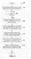
- FIG. 2 is a diagram illustrating a flow chart for video latency reduction by real-time warping according to one aspect of the subject disclosure.
- FIG. 3 is a diagram illustrating a reduced control loop latency according to one aspect of the subject disclosure.
- FIG. 4 is a diagram illustrating an example of a camera geometry and field of view at a digital video frame capture time according to one aspect of the subject disclosure.
- FIG. 5 is a diagram illustrating an example of a camera geometry and field of view at a digital video frame receive time according to one aspect of the subject disclosure.
- FIG. 6 is a diagram illustrating an example of an original geometric image model of a digital video frame at a frame capture time according to one aspect of the subject disclosure.
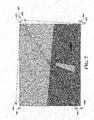
- FIG. 7 is a diagram illustrating an example of an adjusted geometric image model overlaid onto the original geometric image model of FIG. 6 to capture a warped image according to one aspect of the subject disclosure.
- FIG. 8 is a diagram illustrating an example of the warped image of FIG. 7 , re-projected according to the adjusted geometric image model to form a re-projected image according to one aspect of the subject disclosure.
- FIG. 9 is a diagram illustrating an example of a camera geometry and field of view at a digital video frame capture time, including a ground plane, according to one aspect of the subject disclosure.
- FIG. 10 is a diagram illustrating an example of a camera geometry and field of view at a digital video frame receive time, including a ground plane, according to one aspect of the subject disclosure.
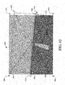
- FIG. 11 is a diagram illustrating an example of an original geometric image model of a digital video frame at a frame capture time, including a ground plane, according to one aspect of the subject disclosure.
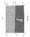
- FIG. 12 is a diagram illustrating an example of an adjusted geometric image model overlaid onto the original geometric image model to capture a warped image according to one aspect of the subject disclosure.
- FIG. 13 is a diagram illustrating an example of the warped image of FIG. 12 , re-projected according to the adjusted geometric image model to form a re-projected image according to one aspect of the subject disclosure.
- Digital video is popular due to its high quality, ease of transmission, and encryption capability.
- digital video requires compression to retain reasonable bandwidth.
- MPEG motion picture experts group
- the latency required to decode and display the video is in the range of 200-400 milliseconds (ms).
- ms milliseconds
- the received digital video is not representative of a scene in real-time due to the latency caused by the compression.
- This digital video latency is commonly experienced by viewers of digital television who do not notice that the content displayed on their screen does not represent a real-time view for live events.
- Remote control tasks require reacting to displayed images with precision, which varies in difficulty depending on the magnitude of the digital video latency.
- One example of a remote control task is the remote control of a vehicle, such as a remotely piloted unmanned aerial vehicle (UAV).
- UAV remotely piloted unmanned aerial vehicle
- digital video latency prohibits the viewing of changes to a scene in real-time since changes may occur between the time a scene is captured and a time at which the scene is displayed at a remote location.
- the total latency for the remote control of a vehicle may depend on properties such as the vehicle response, a radio communication link, and the digital video latency.
- a total latency in excess of, for example, 200 ms may cause pilot induced oscillations because a display of the digital video frames from an on-board camera does not reflect the commands issued to the vehicle, which causes the pilot to issue additional commands, resulting in a loss of control.
- each frame of digital video is re-projected (warped) to approximate a geometry of a future video frame in real-time.
- a camera geometry for each digital video frame captured by the camera is recorded according to a location of the camera at a digital video frame capture time. Subsequently, an estimate is made of an actual, current camera geometry at a time a digital video frame is received.
- a difference between the recorded geometry and the current camera geometry (location) is used to re-project or warp the video image to correct for the difference in the form of a re-projected image.
- a current camera geometry may be provided by sensors, such as an inertial navigation system, or can be estimated from the scene itself.
- digital video latency may refer to a time delay between a digital video frame capture time and a time at which the video frame is displayed, which may be in the range of 100 to 200 milliseconds (ms).
- real-time warping may refer to the remapping of an original geometric image model of digital video frame according to an adjusted geometric image model representing an approximate real-time camera location to approximate a geometry of a future video frame in real-time.
- a geometric image model may refer to an intersection between a camera field of view and a plane perpendicular to a camera focal plane at a predetermined distance in front of the camera, such that an original geometric image model (original image model) may refer to a field of view from a remote camera used to capture the digital video frame at a time that the digital video frame is captured, and an adjusted geometric image model (adjusted image model) may refer to a field of view from the remote camera at a time a digital video frame is received.
- original geometric image model original image model
- adjusted geometric image model adjusted image model
- FIG. 1 illustrates a computer navigation system 100 in accordance with the disclosed aspects.
- System 100 is operable to access and receive digital video frames 162 and to access and receive vehicle (camera) location information 164 .
- System 100 may comprise a computer platform 110 having a memory 130 operable to store data, logic, and applications executable by a processor 120 .
- a user may interact with system 100 and its resident applications through one or more user interfaces 102 , which may include one or more input devices 104 and one or more output devices 106 .
- system 100 may exchange communications with external devices 310 / 340 ( FIG. 3 ) and/or networks through a communications module 114 .
- Computer platform 110 is operable to transmit data across a network, and is operable to receive and execute routines and applications and display data generated within system 100 or received from any network device or other computer device connected to the network or connected to system 100 .
- Computer platform 130 may be embodied in, for example, one or any combination of hardware, firmware, software, data and executable instructions.
- Memory 130 may comprise one or any combination of volatile and nonvolatile memory, such as read-only and/or random-access memory (RAM and ROM), EPROM, EEPROM, flash cards, flash memory cells, an electronic file system, and any memory common to computer platforms. Further, memory 130 may include one or more of any secondary or tertiary storage device, such as magnetic media, optical media, tape, or soft or hard disk, including removable memory mechanisms.
- volatile and nonvolatile memory such as read-only and/or random-access memory (RAM and ROM), EPROM, EEPROM, flash cards, flash memory cells, an electronic file system, and any memory common to computer platforms.
- memory 130 may include one or more of any secondary or tertiary storage device, such as magnetic media, optical media, tape, or soft or hard disk, including removable memory mechanisms.
- processor 120 may be one or more of an application-specific integrated circuit (“ASIC”), a chipset, a processor, a logic circuit, and any other data processing device.
- processor 120 or another processor such as an ASIC, may execute an application programming interface (API) layer 112 that interfaces with any resident programs stored in memory 130 of system 100 .
- API 112 may be a runtime environment executing on system 100 .
- API 112 in combination with navigation menu 144 , may be used control the operation of a remote vehicle.
- processor 120 may include graphic processing unit (GPU) 122 embodied in hardware, firmware, software, data, executable instructions and combinations thereof, which enable video latency reduction according to one embodiment.
- GPU graphic processing unit
- GPU 122 in combination with video re-projection logic 142 of latency reduction module 140 may enable video latency reduction by real-time warping.
- communications module 114 may be embodied in hardware, firmware, software, data, executable instructions and combinations thereof, and is operable to enable communications among the various wireless data links.
- communication module 114 may include the requisite hardware, firmware, software, data, executable instructions and combinations thereof, including transmit and receive chain components for establishing a wireless communication connection.
- communication module 114 is operable to receive a plurality of digital video frames 162 and the associated respective camera locations 164 at a video frame capture time, and forwards them to real-time image selector 150 or provides image selector 150 with access to the data.
- communication module 114 is operable to receive navigation data regarding a camera location 164 at a video frame receive time and either forwards them to image selector 150 or provides image selector 150 with access to the data. Subsequently, for example, communications module 114 is operable to forward digital video content to other device components for further processing.
- input device 104 may include a mechanism such as a key or keyboard, a navigation mechanism (e.g. a joy stick), a mouse, a touch-screen display, a microphone in association with a voice recognition module, etc.
- input device 104 provides an interface for receiving user input, such as to activate or interact with an application or module on a remote vehicle.
- output device 102 may include a display, an audio speaker, a haptic feedback mechanism, etc.
- user interface 102 may comprise one or any combination of input devices 104 and/or output devices 106 .
- FIG. 2 is a diagram illustrating a flowchart 200 for real time video warping, according to one aspect of the present disclosure.
- a camera location is recorded for each digital video frame at a frame capture time.
- an original geometric image model of a camera field of view at the frame capture time is determined.
- the original geometric image model is modified according to an approximate field of view of the camera at a video frame receive time.
- the adjusted geometric image model is overlaid onto the original geometric image model to capture a warped image.
- a field of view of the warped image is reduced to eliminate one or more edges of the warped image to form a re-projected image.
- the re-projected image is displayed to approximate a real-time field of view from the camera at the video frame receive time.
- latency reduction module 140 in combination with GPU 122 may be operable to perform the features of FIG. 2 .
- latency reduction module 140 may include video re-projection logic 142 and navigation menu 144 .
- navigation menu 144 may be provided to control the operation of a vehicle.
- real-time image selector 150 may be responsible for receiving digital video frames 162 and camera locations 164 for storage within storage device 160 .
- a digital video latency may refer to a delay between a time at which a video frame is captured by a camera 310 ( FIG. 3 ) and a time at which the video frame is received at communications module 114 .
- real-time image selector 150 may determine a camera location 164 at the time the frame is received, which is later in time than the time at which the frame was captured due to video latency.
- original image model 166 may represent a field of view of the camera at a time that digital video frame was captured.
- adjusted image model 168 may approximate a field of view of a camera at real-time, which may be a time at which the digital video frame was received.
- video re-projection logic 142 may re-project digital video frame 162 using the adjusted image model 168 to approximate a current real-time view from a camera 310 ( FIG. 3 ).
- FIG. 3 is a block diagram illustrating a reduced control loop latency 300 , according to one aspect of the present disclosure.
- input device 104 may represent a joystick or controller for controlling a vehicle.
- Blocks 302 - 308 represent latency times for directing a command from controller 104 to a remote vehicle.
- a video frame latency path 330 ( 332 - 336 ) is shown in relation to a video warping path 320 that includes blocks 322 - 326 .
- the total latency time provided by video latency path 330 include a total of 243 ms.
- a video warping path 320 which includes a total latency time of 28 ms.
- a camera location at a time when a video frame is received may be determined using for example, an inertial navigation system 340 which may provide a sample vehicle position and attitude, including a roll, pitch, and yaw for an unmanned aerial vehicle (UAV).
- UAV unmanned aerial vehicle
- GPS global positioning system
- the delay required to receive or approximate a real-time location of camera 310 is less than the video frame latency path 330 .
- a geometric image model may be used to approximate a current real-time location of camera 310 .
- an original digital frame image may be remapped according to the approximated model to provide a warped image, for example as shown in FIGS. 8 and 13 .
- FIG. 4 is a diagram 400 illustrating a location 402 , of camera 310 at a video frame capture time. Representatively, a horizontal distance 404 to an image plane 410 is shown. Also illustrated is a field of view of camera 310 , which intersects plane 410 at points a 406 and b 408 . FIG. 4 is a simplified view of, for example, a frustum view of the camera field of view intersection with image plane 410 .
- FIG. 5 is a diagram 420 illustrating a location 422 of camera 310 at a time at which a digital video frame is received, which may be referred to herein as a real-time location of camera 310 .
- a frustum view of the intersection between the field of view of camera 310 and image plane 430 is shown based on elements a′ 416 and b′ 418.
- FIG. 6 is a block diagram illustrating a frustum view 440 at a video frame capture time. Representatively, a runway is shown in the distance. In the aspect described in FIG. 6 , an attitude of a vehicle is considered due to a distance from the runway. As further described with reference to FIGS. 9-13 , a ground plane may be included to allow for vehicle takeoffs and landings.
- frustum view 440 may be referred to as an original geometric image model of a digital video frame, which represents a field of view of a camera at a time that the digital video frame is captured.
- this latent image may be modified to form a warped image to illustrate a real-time location of camera 310 .
- FIG. 7 is a diagram, which illustrates the overlaying of an adjusted geometric image model 450 onto original geometric image model 440 .
- the adjusted geometric image model 450 is represented by points a′ 416 , b′ 418 , c′ 452 , and d′ 454 .
- a warped image may be determined to approximate a real-time camera view, for example, as shown in FIG. 8 .
- FIG. 8 represents a re-mapping of an original geometric image according to an adjusted geometric image model based on points a′ 416 , b′ 418 , c′ 452 , and d′ 454 .
- warped image 460 is no longer aligned with the mapping based on the adjusted geometric model and includes various edges (gaps) that are out of alignment with the adjusted model.
- a field of view of the original geometric image model may be larger than a field of view for a re-projected image 480 .
- This re-projected image field of view 470 is shown such that an image is captured, based on the reduced field of view, to provide re-projected image 480 .
- the latent original image is re-projected to represent a real-time field of view from the camera, which will enable more accurate control of, for example, a vehicle, including a camera as well as a remote control application.
- FIGS. 9-13 represent similar features as described with reference to FIGS. 5-8 , however, shown to include a ground plane 514 as introduced in FIG. 9 .
- a subsequent location 522 of the camera 310 is captured to provide an adjusted geometric image model.
- an original geometric image model 540 includes a ground plane identified by point numerals 512 (c) and 546 (e), based on original mapping points a 506 , b 508 , c 542 , and d 544 .
- FIG. 13 is a diagram, which illustrates the overlaying of an adjusted geometric image model 550 onto original geometric image model 540 .
- the adjusted geometric image model 550 is represented by points a′ 516 , b′ 518 , c′ 552 , and d′ 554 , as well as ground plane points c′ 524 and e′ 556 .
- a warped image may be determined to approximate a real-time camera view, for example, as shown in FIG. 13 .
- FIG. 13 represents a re-mapping of an original geometric image model 540 according to an adjusted geometric image model 550 based on points a′ 516 , b′ 518 , c′ 552 , and d′ 554 , as well as ground plane points c′ 524 and e′ 556 .
- warped image 560 is no longer aligned with the mapping based on the adjusted geometric model 550 and includes various edges (gaps) that are out of alignment with the adjusted model.
- a field of view of the original geometric image model 550 may be larger than a field of view for a re-projected image 580 .
- This re-projected image field of view 570 is shown such that an image is captured, based on the reduced field of view, to provide re-projected image 580 .
- the latent original image is re-projected to represents a real-time field of view from the camera, which will enable more accurate control for landing a vehicle, including a camera as well as a remote control application.
- aspects of the subject technology bypass the extra latency inherent to digital compression/decompression and delay by using a wireless data link and an inertial navigation system to provide a low latency data path for determining a real-time location of a camera included within a vehicle.
- a relative position and attitude indicated by the digital video data may be corrected to approximate a geometry of a future video frame in real-time.
- the subject technology may be applied in radio communication, wireless communication, and electronics.
- the subject technology may be applied in non-aerial vehicle control, for example, such as standard automobiles.
- the subject technology is related to video latency reduction.
- the subject technology may be used in various markets, including for example and without limitation, remote control tasks based on a video image that require low latency.
- the video reduction latency is described for landing a remotely piloted vehicle. The described aspects, however, are not limited to landing a remotely piloted vehicle, and may be applied to any control task that requires low latency.
- the embodiments described herein may be implemented by hardware, software, firmware, middleware, microcode, or any combination thereof.
- the systems and/or methods When the systems and/or methods are implemented in software, firmware, middleware or microcode, program code or code segments, they may be stored in a machine-readable medium, such as a storage component.
- a code segment may represent a procedure, a function, a subprogram, a program, a routine, a subroutine, a module, a software package, a class, or any combination of instructions, data structures, or program statements.
- a code segment may be coupled to another code segment or a hardware circuit by passing and/or receiving information, data, arguments, parameters, or memory contents. Information, arguments, parameters, data, etc. may be passed, forwarded, or transmitted using any suitable means including memory sharing, message passing, token passing, network transmission, etc.
- the techniques described herein may be implemented with modules (e.g., procedures, functions, and so on) that perform the functions described herein.
- the software codes may be stored in memory units and executed by processors.
- the memory unit may be implemented within the processor or external to the processor, in which case it can be communicatively coupled to the processor through various means as is known in the art.
- various aspects or features described herein may be implemented as a method, apparatus, or article of manufacture using standard programming and/or engineering techniques.
- article of manufacture as used herein is intended to encompass a computer program accessible from any computer-readable device, carrier, or media.
- computer-readable media can include but are not limited to magnetic storage devices (e.g., hard disk, floppy disk, magnetic strips, etc.), optical disks (e.g., compact disk (CD), digital versatile disk (DVD), etc.), smart cards, and flash memory devices (e.g., EPROM, card, stick, key drive, etc.).
- various storage media described herein can represent one or more devices and/or other machine-readable media for storing information.
- the term “machine-readable medium” can include, without being limited to, wireless channels and various other media capable of storing, containing, and/or carrying instruction(s) and/or data.
- a phrase such as an “aspect” does not imply that such aspect is essential to the subject technology or that such aspect applies to all configurations of the subject technology.
- a disclosure relating to an aspect may apply to all configurations, or one or more configurations.
- An aspect may provide one or more examples.
- a phrase such as an aspect may refer to one or more aspects and vice versa.
- a phrase such as an “embodiment” does not imply that such embodiment is essential to the subject technology or that such embodiment applies to all configurations of the subject technology.
- a disclosure relating to an embodiment may apply to all embodiments, or one or more embodiments.
- An embodiment may provide one or more examples.
- a phrase such an embodiment may refer to one or more embodiments and vice versa.
- a phrase such as a “configuration” does not imply that such configuration is essential to the subject technology or that such configuration applies to all configurations of the subject technology.
- a disclosure relating to a configuration may apply to all configurations, or one or more configurations.
- a configuration may provide one or more examples.
- a phrase such a configuration may refer to one or more configurations and vice versa.
Abstract
Description
- An aspect of the present disclosure relates to the field of digital video, and more particularly, to digital video latency reduction of a received digital video frame captured by a remote camera.
- Digital video is popular due to its high quality, ease of transmission, and encryption capability. Unfortunately, digital video requires compression to retain reasonable bandwidth. This generally creates several video frames of latency, adding as much as 200-400 milliseconds (ms) of delay. In other words, the received digital video is not representative of a scene in real-time due to the latency caused by the compression. Highly interactive tasks, such as remote control tasks require low latency. Remote control tasks require reacting to displayed images with precision, which varies in difficulty depending on the magnitude of the latency. Some current methods for reducing video latency focus on reducing the actual latency of a video stream. Other techniques provide completely synthetic views.
- One aspect of the subject disclosure describes a method for digital video latency reduction of a received digital video frame captured by a remote camera. In one aspect, an image model of the received digital video frame is adjusted according to an approximate field of view from the remote camera at a time the digital video frame is received to form an adjusted image model. In one aspect, the adjusted image model may be overlaid onto the original image model of the received digital video frame to capture a warped image. In one aspect, the warped image is re-projected according to the adjusted image model to form a re-projected image. The re-projected image may then be displayed to approximate a real-time field of view from the remote camera used to capture the digital video frame. In one aspect, an attitude and runway alignment of an unmanned aerial vehicle may be controlled using a displayed, re-projected image having an on-board, remote camera.
- It is understood that other configurations of the subject technology will become readily apparent to those skilled in the art from the following detailed description, wherein various configurations of the subject technology are shown and described by way of illustration. As will be realized, the subject technology is capable of other and different configurations and its several details are capable of modification in various other respects, all without departing from the scope of the subject technology. Accordingly, the drawings and detailed description are to be regarded as illustrative in nature and not as restrictive.
-
FIG. 1 is a block diagram illustrating a computer navigation system according to one aspect of the subject disclosure. -
FIG. 2 is a diagram illustrating a flow chart for video latency reduction by real-time warping according to one aspect of the subject disclosure. -
FIG. 3 is a diagram illustrating a reduced control loop latency according to one aspect of the subject disclosure. -
FIG. 4 is a diagram illustrating an example of a camera geometry and field of view at a digital video frame capture time according to one aspect of the subject disclosure. -
FIG. 5 is a diagram illustrating an example of a camera geometry and field of view at a digital video frame receive time according to one aspect of the subject disclosure. -
FIG. 6 is a diagram illustrating an example of an original geometric image model of a digital video frame at a frame capture time according to one aspect of the subject disclosure. -
FIG. 7 is a diagram illustrating an example of an adjusted geometric image model overlaid onto the original geometric image model ofFIG. 6 to capture a warped image according to one aspect of the subject disclosure. -
FIG. 8 is a diagram illustrating an example of the warped image ofFIG. 7 , re-projected according to the adjusted geometric image model to form a re-projected image according to one aspect of the subject disclosure. -
FIG. 9 is a diagram illustrating an example of a camera geometry and field of view at a digital video frame capture time, including a ground plane, according to one aspect of the subject disclosure. -
FIG. 10 is a diagram illustrating an example of a camera geometry and field of view at a digital video frame receive time, including a ground plane, according to one aspect of the subject disclosure. -
FIG. 11 is a diagram illustrating an example of an original geometric image model of a digital video frame at a frame capture time, including a ground plane, according to one aspect of the subject disclosure. -
FIG. 12 is a diagram illustrating an example of an adjusted geometric image model overlaid onto the original geometric image model to capture a warped image according to one aspect of the subject disclosure. -
FIG. 13 is a diagram illustrating an example of the warped image ofFIG. 12 , re-projected according to the adjusted geometric image model to form a re-projected image according to one aspect of the subject disclosure. - The detailed description set forth below is intended as a description of various configurations of the subject technology and is not intended to represent the only configurations in which the subject technology may be practiced. The appended drawings are incorporated herein and constitute a part of the detailed description. The detailed description includes specific details for the purpose of providing a thorough understanding of the subject technology. However, it will be apparent to those skilled in the art that the subject technology may be practiced without these specific details. In some instances, well-known structures and components are shown in block diagram form in order to avoid obscuring the concepts of the subject technology. Like components are labeled with identical element numbers for ease of understanding.
- Digital video is popular due to its high quality, ease of transmission, and encryption capability. Unfortunately, digital video requires compression to retain reasonable bandwidth. For example, if digital video is encoded using motion picture experts group (MPEG) technology, the latency required to decode and display the video is in the range of 200-400 milliseconds (ms). In other words, the received digital video is not representative of a scene in real-time due to the latency caused by the compression. This digital video latency is commonly experienced by viewers of digital television who do not notice that the content displayed on their screen does not represent a real-time view for live events.
- While digital video latency may be acceptable to viewers of digital television, digital video latency is unacceptable for highly interactive tasks, such as remote control tasks. Remote control tasks require reacting to displayed images with precision, which varies in difficulty depending on the magnitude of the digital video latency. One example of a remote control task is the remote control of a vehicle, such as a remotely piloted unmanned aerial vehicle (UAV). Unfortunately, digital video latency prohibits the viewing of changes to a scene in real-time since changes may occur between the time a scene is captured and a time at which the scene is displayed at a remote location. The total latency for the remote control of a vehicle may depend on properties such as the vehicle response, a radio communication link, and the digital video latency. A total latency in excess of, for example, 200 ms may cause pilot induced oscillations because a display of the digital video frames from an on-board camera does not reflect the commands issued to the vehicle, which causes the pilot to issue additional commands, resulting in a loss of control.
- According to various aspects of the subject disclosure, digital video latency reduction by real-time warping is described. In one aspect, each frame of digital video is re-projected (warped) to approximate a geometry of a future video frame in real-time. In one aspect, a camera geometry for each digital video frame captured by the camera is recorded according to a location of the camera at a digital video frame capture time. Subsequently, an estimate is made of an actual, current camera geometry at a time a digital video frame is received. In one aspect, a difference between the recorded geometry and the current camera geometry (location) is used to re-project or warp the video image to correct for the difference in the form of a re-projected image. When the re-projected image is displayed, the content of the original image does not represent a real-time image due to the above-mentioned delay in receiving the image. The re-projected image, although based on a non-real-time image, will approximate a real-time field of view from the camera at the video frame receive time. In one aspect of the subject disclosure, a current camera geometry may be provided by sensors, such as an inertial navigation system, or can be estimated from the scene itself.
- As described herein, digital video latency may refer to a time delay between a digital video frame capture time and a time at which the video frame is displayed, which may be in the range of 100 to 200 milliseconds (ms). As further described herein, real-time warping may refer to the remapping of an original geometric image model of digital video frame according to an adjusted geometric image model representing an approximate real-time camera location to approximate a geometry of a future video frame in real-time. As further described herein, a geometric image model (image model) may refer to an intersection between a camera field of view and a plane perpendicular to a camera focal plane at a predetermined distance in front of the camera, such that an original geometric image model (original image model) may refer to a field of view from a remote camera used to capture the digital video frame at a time that the digital video frame is captured, and an adjusted geometric image model (adjusted image model) may refer to a field of view from the remote camera at a time a digital video frame is received.
-
FIG. 1 illustrates acomputer navigation system 100 in accordance with the disclosed aspects.System 100 is operable to access and receive digital video frames 162 and to access and receive vehicle (camera)location information 164.System 100 may comprise acomputer platform 110 having amemory 130 operable to store data, logic, and applications executable by aprocessor 120. A user may interact withsystem 100 and its resident applications through one ormore user interfaces 102, which may include one ormore input devices 104 and one ormore output devices 106. Additionally,system 100 may exchange communications withexternal devices 310/340 (FIG. 3 ) and/or networks through acommunications module 114. -
Computer platform 110 is operable to transmit data across a network, and is operable to receive and execute routines and applications and display data generated withinsystem 100 or received from any network device or other computer device connected to the network or connected tosystem 100.Computer platform 130 may be embodied in, for example, one or any combination of hardware, firmware, software, data and executable instructions. -
Memory 130 may comprise one or any combination of volatile and nonvolatile memory, such as read-only and/or random-access memory (RAM and ROM), EPROM, EEPROM, flash cards, flash memory cells, an electronic file system, and any memory common to computer platforms. Further,memory 130 may include one or more of any secondary or tertiary storage device, such as magnetic media, optical media, tape, or soft or hard disk, including removable memory mechanisms. - Further,
processor 120 may be one or more of an application-specific integrated circuit (“ASIC”), a chipset, a processor, a logic circuit, and any other data processing device. In some aspects,processor 120, or another processor such as an ASIC, may execute an application programming interface (API)layer 112 that interfaces with any resident programs stored inmemory 130 ofsystem 100.API 112 may be a runtime environment executing onsystem 100. In one aspect,API 112, in combination withnavigation menu 144, may be used control the operation of a remote vehicle. - Additionally,
processor 120 may include graphic processing unit (GPU) 122 embodied in hardware, firmware, software, data, executable instructions and combinations thereof, which enable video latency reduction according to one embodiment. For example,GPU 122 in combination withvideo re-projection logic 142 oflatency reduction module 140 may enable video latency reduction by real-time warping. - Further,
communications module 114 may be embodied in hardware, firmware, software, data, executable instructions and combinations thereof, and is operable to enable communications among the various wireless data links. For example,communication module 114 may include the requisite hardware, firmware, software, data, executable instructions and combinations thereof, including transmit and receive chain components for establishing a wireless communication connection. - Further, for example,
communication module 114 is operable to receive a plurality of digital video frames 162 and the associatedrespective camera locations 164 at a video frame capture time, and forwards them to real-time image selector 150 or providesimage selector 150 with access to the data. Similarly, for example,communication module 114 is operable to receive navigation data regarding acamera location 164 at a video frame receive time and either forwards them to imageselector 150 or providesimage selector 150 with access to the data. Subsequently, for example,communications module 114 is operable to forward digital video content to other device components for further processing. - Additionally, one or
more input devices 104 for generating inputs intosystem 100, and one ormore output devices 106 for generating information for consumption by the user of the system are provided. For example,input device 104 may include a mechanism such as a key or keyboard, a navigation mechanism (e.g. a joy stick), a mouse, a touch-screen display, a microphone in association with a voice recognition module, etc. In certain aspects,input device 104 provides an interface for receiving user input, such as to activate or interact with an application or module on a remote vehicle. Further, for example,output device 102 may include a display, an audio speaker, a haptic feedback mechanism, etc. Further,user interface 102 may comprise one or any combination ofinput devices 104 and/oroutput devices 106. -
FIG. 2 is a diagram illustrating aflowchart 200 for real time video warping, according to one aspect of the present disclosure. Atprocess block 202, a camera location is recorded for each digital video frame at a frame capture time. Atprocess block 204, it is determined whether a frame is received. Once received, at process block 206 an original geometric image model of a camera field of view at the frame capture time is determined. Atprocess block 208, the original geometric image model is modified according to an approximate field of view of the camera at a video frame receive time. Atprocess block 210, the adjusted geometric image model is overlaid onto the original geometric image model to capture a warped image. Atprocess block 212, a field of view of the warped image is reduced to eliminate one or more edges of the warped image to form a re-projected image. At process block 214 the re-projected image is displayed to approximate a real-time field of view from the camera at the video frame receive time. - Referring again to
FIG. 1 ,latency reduction module 140 in combination withGPU 122 may be operable to perform the features ofFIG. 2 . Representatively,latency reduction module 140, may includevideo re-projection logic 142 andnavigation menu 144. In one aspect,navigation menu 144 may be provided to control the operation of a vehicle. As shown inFIG. 1 , real-time image selector 150, may be responsible for receiving digital video frames 162 andcamera locations 164 for storage withinstorage device 160. In one aspect, a digital video latency may refer to a delay between a time at which a video frame is captured by a camera 310 (FIG. 3 ) and a time at which the video frame is received atcommunications module 114. - Referring again to
FIG. 1 , in response to a receiveddigital video frame 162, real-time image selector 150 may determine acamera location 164 at the time the frame is received, which is later in time than the time at which the frame was captured due to video latency. According to the described aspects,original image model 166 may represent a field of view of the camera at a time that digital video frame was captured. As further shown inFIG. 1 , adjustedimage model 168 may approximate a field of view of a camera at real-time, which may be a time at which the digital video frame was received. According to the described aspects, although the receiveddigital video frame 162 is not current (due to the video latency),video re-projection logic 142 may re-projectdigital video frame 162 using the adjustedimage model 168 to approximate a current real-time view from a camera 310 (FIG. 3 ). -
FIG. 3 is a block diagram illustrating a reducedcontrol loop latency 300, according to one aspect of the present disclosure. As shown inFIG. 3 ,input device 104 may represent a joystick or controller for controlling a vehicle. Blocks 302-308 represent latency times for directing a command fromcontroller 104 to a remote vehicle. As further shown inFIG. 3 , a video frame latency path 330 (332-336) is shown in relation to avideo warping path 320 that includes blocks 322-326. The total latency time provided byvideo latency path 330 include a total of 243 ms. To avoid the latency caused byvideo latency path 330, avideo warping path 320 is described, which includes a total latency time of 28 ms. Representatively, a camera location at a time when a video frame is received may be determined using for example, aninertial navigation system 340 which may provide a sample vehicle position and attitude, including a roll, pitch, and yaw for an unmanned aerial vehicle (UAV). Alternatively, a global positioning system (GPS) may also be used to provide a current location ofcamera 310. - As shown in
FIG. 3 , the delay required to receive or approximate a real-time location ofcamera 310 is less than the videoframe latency path 330. By taking advantage of the reduced videoframe warping path 320, a geometric image model may be used to approximate a current real-time location ofcamera 310. Using this approximate model, an original digital frame image may be remapped according to the approximated model to provide a warped image, for example as shown inFIGS. 8 and 13 . -
FIG. 4 is a diagram 400 illustrating alocation 402, ofcamera 310 at a video frame capture time. Representatively, ahorizontal distance 404 to animage plane 410 is shown. Also illustrated is a field of view ofcamera 310, which intersectsplane 410 at points a 406 andb 408.FIG. 4 is a simplified view of, for example, a frustum view of the camera field of view intersection withimage plane 410. -
FIG. 5 is a diagram 420 illustrating alocation 422 ofcamera 310 at a time at which a digital video frame is received, which may be referred to herein as a real-time location ofcamera 310. Based on the real-time location 422 ofcamera 310, a frustum view of the intersection between the field of view ofcamera 310 andimage plane 430 is shown based on elements a′ 416 and b′ 418. -
FIG. 6 is a block diagram illustrating afrustum view 440 at a video frame capture time. Representatively, a runway is shown in the distance. In the aspect described inFIG. 6 , an attitude of a vehicle is considered due to a distance from the runway. As further described with reference toFIGS. 9-13 , a ground plane may be included to allow for vehicle takeoffs and landings. - As described herein,
frustum view 440 may be referred to as an original geometric image model of a digital video frame, which represents a field of view of a camera at a time that the digital video frame is captured. Unfortunately, for the reasons described above, by the time the digital video frame represented byFIG. 6 is received by, for example,system 100, that digital video frame no longer represents a real-time view fromcamera 310. According to one aspect of the present disclosure, this latent image may be modified to form a warped image to illustrate a real-time location ofcamera 310. -
FIG. 7 is a diagram, which illustrates the overlaying of an adjustedgeometric image model 450 onto originalgeometric image model 440. Representatively, the adjustedgeometric image model 450 is represented by points a′ 416, b′ 418, c′ 452, and d′ 454. Once the adjustedgeometric image 450 is overlaid onto the originalgeometric image model 440, a warped image may be determined to approximate a real-time camera view, for example, as shown inFIG. 8 . -
FIG. 8 represents a re-mapping of an original geometric image according to an adjusted geometric image model based on points a′ 416, b′ 418, c′ 452, and d′ 454. As shown inFIG. 8 ,warped image 460 is no longer aligned with the mapping based on the adjusted geometric model and includes various edges (gaps) that are out of alignment with the adjusted model. In one aspect of the present disclosure, a field of view of the original geometric image model may be larger than a field of view for are-projected image 480. This re-projected image field ofview 470 is shown such that an image is captured, based on the reduced field of view, to providere-projected image 480. As shown inFIG. 8 , the latent original image is re-projected to represent a real-time field of view from the camera, which will enable more accurate control of, for example, a vehicle, including a camera as well as a remote control application. -
FIGS. 9-13 represent similar features as described with reference toFIGS. 5-8 , however, shown to include aground plane 514 as introduced inFIG. 9 . As illustrated inFIG. 10 , asubsequent location 522 of thecamera 310 is captured to provide an adjusted geometric image model. As shown inFIG. 11 , an originalgeometric image model 540 includes a ground plane identified by point numerals 512 (c) and 546 (e), based on original mapping points a 506,b 508,c 542, andd 544.FIG. 13 is a diagram, which illustrates the overlaying of an adjustedgeometric image model 550 onto originalgeometric image model 540. Representatively, the adjustedgeometric image model 550 is represented by points a′ 516, b′ 518, c′ 552, and d′ 554, as well as ground plane points c′ 524 and e′ 556. Once the adjustedgeometric image model 550 is overlaid onto the originalgeometric image model 540, a warped image may be determined to approximate a real-time camera view, for example, as shown inFIG. 13 . -
FIG. 13 represents a re-mapping of an originalgeometric image model 540 according to an adjustedgeometric image model 550 based on points a′ 516, b′ 518, c′ 552, and d′ 554, as well as ground plane points c′ 524 and e′ 556. As shown inFIG. 13 ,warped image 560 is no longer aligned with the mapping based on the adjustedgeometric model 550 and includes various edges (gaps) that are out of alignment with the adjusted model. In one aspect of the present disclosure, a field of view of the originalgeometric image model 550 may be larger than a field of view for are-projected image 580. This re-projected image field ofview 570 is shown such that an image is captured, based on the reduced field of view, to providere-projected image 580. As shown inFIG. 13 , the latent original image is re-projected to represents a real-time field of view from the camera, which will enable more accurate control for landing a vehicle, including a camera as well as a remote control application. - Aspects of the subject technology bypass the extra latency inherent to digital compression/decompression and delay by using a wireless data link and an inertial navigation system to provide a low latency data path for determining a real-time location of a camera included within a vehicle. Although received digital video data from a vehicle including the camera is still latent, a relative position and attitude indicated by the digital video data may be corrected to approximate a geometry of a future video frame in real-time. In some aspects, the subject technology may be applied in radio communication, wireless communication, and electronics. In some aspects, the subject technology may be applied in non-aerial vehicle control, for example, such as standard automobiles.
- In accordance with various aspects of the subject disclosure, the subject technology is related to video latency reduction. In some aspects, the subject technology may be used in various markets, including for example and without limitation, remote control tasks based on a video image that require low latency. For example, the video reduction latency, according to one aspect, is described for landing a remotely piloted vehicle. The described aspects, however, are not limited to landing a remotely piloted vehicle, and may be applied to any control task that requires low latency.
- It is to be understood that the embodiments described herein may be implemented by hardware, software, firmware, middleware, microcode, or any combination thereof. When the systems and/or methods are implemented in software, firmware, middleware or microcode, program code or code segments, they may be stored in a machine-readable medium, such as a storage component. A code segment may represent a procedure, a function, a subprogram, a program, a routine, a subroutine, a module, a software package, a class, or any combination of instructions, data structures, or program statements. A code segment may be coupled to another code segment or a hardware circuit by passing and/or receiving information, data, arguments, parameters, or memory contents. Information, arguments, parameters, data, etc. may be passed, forwarded, or transmitted using any suitable means including memory sharing, message passing, token passing, network transmission, etc.
- For a software implementation, the techniques described herein may be implemented with modules (e.g., procedures, functions, and so on) that perform the functions described herein. The software codes may be stored in memory units and executed by processors. The memory unit may be implemented within the processor or external to the processor, in which case it can be communicatively coupled to the processor through various means as is known in the art.
- Moreover, various aspects or features described herein may be implemented as a method, apparatus, or article of manufacture using standard programming and/or engineering techniques. The term “article of manufacture” as used herein is intended to encompass a computer program accessible from any computer-readable device, carrier, or media. For example, computer-readable media can include but are not limited to magnetic storage devices (e.g., hard disk, floppy disk, magnetic strips, etc.), optical disks (e.g., compact disk (CD), digital versatile disk (DVD), etc.), smart cards, and flash memory devices (e.g., EPROM, card, stick, key drive, etc.). Additionally, various storage media described herein can represent one or more devices and/or other machine-readable media for storing information. The term “machine-readable medium” can include, without being limited to, wireless channels and various other media capable of storing, containing, and/or carrying instruction(s) and/or data.
- It is understood that the specific order or hierarchy of steps in the processes disclosed is an illustration of exemplary approaches. Based upon design preferences, it is understood that the specific order or hierarchy of steps in the processes may be rearranged. Some of the steps may be performed simultaneously. The accompanying method claims present elements of the various steps in a sample order, and are not meant to be limited to the specific order or hierarchy presented.
- The previous description is provided to enable any person skilled in the art to practice the various aspects described herein. The previous description provides various examples of the subject technology, and the subject technology is not limited to these examples. Various modifications to these aspects will be readily apparent to those skilled in the art, and the generic principles defined herein may be applied to other aspects. Thus, the claims are not intended to be limited to the aspects shown herein, but is to be accorded the full scope consistent with the language claims, wherein reference to an element in the singular is not intended to mean “one and only one” unless specifically so stated, but rather “one or more.” Unless specifically stated otherwise, the term “some” refers to one or more. Pronouns in the masculine (e.g., his) include the feminine and neuter gender (e.g., her and its) and vice versa. Headings and subheadings, if any, are used for convenience only and do not limit the invention.
- A phrase such as an “aspect” does not imply that such aspect is essential to the subject technology or that such aspect applies to all configurations of the subject technology. A disclosure relating to an aspect may apply to all configurations, or one or more configurations. An aspect may provide one or more examples. A phrase such as an aspect may refer to one or more aspects and vice versa. A phrase such as an “embodiment” does not imply that such embodiment is essential to the subject technology or that such embodiment applies to all configurations of the subject technology. A disclosure relating to an embodiment may apply to all embodiments, or one or more embodiments. An embodiment may provide one or more examples. A phrase such an embodiment may refer to one or more embodiments and vice versa. A phrase such as a “configuration” does not imply that such configuration is essential to the subject technology or that such configuration applies to all configurations of the subject technology. A disclosure relating to a configuration may apply to all configurations, or one or more configurations. A configuration may provide one or more examples. A phrase such a configuration may refer to one or more configurations and vice versa.
- The word “exemplary” is used herein to mean “serving as an example or illustration.” Any aspect or design described herein as “exemplary” is not necessarily to be construed as preferred or advantageous over other aspects or designs.
- All structural and functional equivalents to the elements of the various aspects described throughout this disclosure that are known or later come to be known to those of ordinary skill in the art are expressly incorporated herein by reference and are intended to be encompassed by the claims. Moreover, nothing disclosed herein is intended to be dedicated to the public regardless of whether such disclosure is explicitly recited in the claims. No claim element is to be construed under the provisions of 35 U.S.C. §112, sixth paragraph, unless the element is expressly recited using the phrase “means for” or, in the case of a method claim, the element is recited using the phrase “step for.” Furthermore, to the extent that the term “include,” “have,” or the like is used in the description or the claims, such term is intended to be inclusive in a manner similar to the term “comprise” as “comprise” is interpreted when employed as a transitional word in a claim.
Claims (20)
Priority Applications (1)
| Application Number | Priority Date | Filing Date | Title |
|---|---|---|---|
| US13/078,832 US8917322B2 (en) | 2011-04-01 | 2011-04-01 | Method and apparatus for digital video latency reduction by real-time warping |
Applications Claiming Priority (1)
| Application Number | Priority Date | Filing Date | Title |
|---|---|---|---|
| US13/078,832 US8917322B2 (en) | 2011-04-01 | 2011-04-01 | Method and apparatus for digital video latency reduction by real-time warping |
Publications (2)
| Publication Number | Publication Date |
|---|---|
| US20120249784A1 true US20120249784A1 (en) | 2012-10-04 |
| US8917322B2 US8917322B2 (en) | 2014-12-23 |
Family
ID=46926731
Family Applications (1)
| Application Number | Title | Priority Date | Filing Date |
|---|---|---|---|
| US13/078,832 Active 2032-03-03 US8917322B2 (en) | 2011-04-01 | 2011-04-01 | Method and apparatus for digital video latency reduction by real-time warping |
Country Status (1)
| Country | Link |
|---|---|
| US (1) | US8917322B2 (en) |
Cited By (7)
| Publication number | Priority date | Publication date | Assignee | Title |
|---|---|---|---|---|
| WO2015130412A1 (en) * | 2014-02-25 | 2015-09-03 | Alcatel Lucent | System and method for reducing latency in video delivery using model |
| US20160360159A1 (en) * | 2012-05-14 | 2016-12-08 | Intuitive Surgical Operations, Inc. | Method for video processing using a buffer |
| US9727055B2 (en) * | 2015-03-31 | 2017-08-08 | Alcatel-Lucent Usa Inc. | System and method for video processing and presentation |
| WO2017197651A1 (en) * | 2016-05-20 | 2017-11-23 | SZ DJI Technology Co., Ltd. | Systems and methods for rolling shutter correction |
| CN110426970A (en) * | 2019-06-25 | 2019-11-08 | 西安爱生无人机技术有限公司 | A kind of unmanned plane camera system and its control method |
| CN113703352A (en) * | 2021-07-27 | 2021-11-26 | 北京三快在线科技有限公司 | Safety early warning method and device based on remote driving |
| US20220094733A1 (en) * | 2019-04-30 | 2022-03-24 | Phantom Auto Inc. | Low latency wireless communication system for teleoperated vehicle environments |
Families Citing this family (3)
| Publication number | Priority date | Publication date | Assignee | Title |
|---|---|---|---|---|
| US9669940B1 (en) * | 2013-06-27 | 2017-06-06 | Rockwell Collins, Inc. | Latency-reducing image generating system, device, and method |
| CN106796481B (en) * | 2016-09-27 | 2018-09-07 | 深圳市大疆创新科技有限公司 | Control method, control device and electronic device |
| US11206393B2 (en) * | 2017-09-22 | 2021-12-21 | Microsoft Technology Licensing, Llc | Display latency measurement system using available hardware |
Citations (29)
| Publication number | Priority date | Publication date | Assignee | Title |
|---|---|---|---|---|
| US4645459A (en) * | 1982-07-30 | 1987-02-24 | Honeywell Inc. | Computer generated synthesized imagery |
| US4805121A (en) * | 1986-05-30 | 1989-02-14 | Dba Systems, Inc. | Visual training apparatus |
| US4835532A (en) * | 1982-07-30 | 1989-05-30 | Honeywell Inc. | Nonaliasing real-time spatial transform image processing system |
| US5796426A (en) * | 1994-05-27 | 1998-08-18 | Warp, Ltd. | Wide-angle image dewarping method and apparatus |
| US5855483A (en) * | 1994-11-21 | 1999-01-05 | Compaq Computer Corp. | Interactive play with a computer |
| US6049619A (en) * | 1996-02-12 | 2000-04-11 | Sarnoff Corporation | Method and apparatus for detecting moving objects in two- and three-dimensional scenes |
| US20020176635A1 (en) * | 2001-04-16 | 2002-11-28 | Aliaga Daniel G. | Method and system for reconstructing 3D interactive walkthroughs of real-world environments |
| US20020180727A1 (en) * | 2000-11-22 | 2002-12-05 | Guckenberger Ronald James | Shadow buffer control module method and software construct for adjusting per pixel raster images attributes to screen space and projector features for digital warp, intensity transforms, color matching, soft-edge blending, and filtering for multiple projectors and laser projectors |
| US6618511B1 (en) * | 1999-12-31 | 2003-09-09 | Stmicroelectronics, Inc. | Perspective correction for panoramic digital camera with remote processing |
| US6804416B1 (en) * | 2001-03-16 | 2004-10-12 | Cognex Corporation | Method and system for aligning geometric object models with images |
| US20040218894A1 (en) * | 2003-04-30 | 2004-11-04 | Michael Harville | Automatic generation of presentations from "path-enhanced" multimedia |
| US20050151963A1 (en) * | 2004-01-14 | 2005-07-14 | Sandeep Pulla | Transprojection of geometry data |
| US20050249426A1 (en) * | 2004-05-07 | 2005-11-10 | University Technologies International Inc. | Mesh based frame processing and applications |
| US20050271301A1 (en) * | 2004-03-07 | 2005-12-08 | Ofer Solomon | Method and system for pseudo-autonomous image registration |
| US20060041375A1 (en) * | 2004-08-19 | 2006-02-23 | Geographic Data Technology, Inc. | Automated georeferencing of digitized map images |
| US20060139475A1 (en) * | 2004-12-23 | 2006-06-29 | Esch John W | Multiple field of view camera arrays |
| US20060285755A1 (en) * | 2005-06-16 | 2006-12-21 | Strider Labs, Inc. | System and method for recognition in 2D images using 3D class models |
| US20070003165A1 (en) * | 2005-06-20 | 2007-01-04 | Mitsubishi Denki Kabushiki Kaisha | Robust image registration |
| US20070135979A1 (en) * | 2005-12-09 | 2007-06-14 | Smartdrive Systems Inc | Vehicle event recorder systems |
| US20070159527A1 (en) * | 2006-01-09 | 2007-07-12 | Samsung Electronics Co., Ltd. | Method and apparatus for providing panoramic view with geometric correction |
| US20070159524A1 (en) * | 2006-01-09 | 2007-07-12 | Samsung Electronics Co., Ltd. | Method and apparatus for providing panoramic view with high speed image matching and mild mixed color blending |
| US20070244608A1 (en) * | 2006-04-13 | 2007-10-18 | Honeywell International Inc. | Ground control station for UAV |
| US20080089577A1 (en) * | 2006-10-11 | 2008-04-17 | Younian Wang | Feature extraction from stereo imagery |
| US20090096790A1 (en) * | 2007-10-11 | 2009-04-16 | Mvtec Software Gmbh | System and method for 3d object recognition |
| US20100008565A1 (en) * | 2008-07-10 | 2010-01-14 | Recon/Optical, Inc. | Method of object location in airborne imagery using recursive quad space image processing |
| US7742077B2 (en) * | 2004-02-19 | 2010-06-22 | Robert Bosch Gmbh | Image stabilization system and method for a video camera |
| US20100295945A1 (en) * | 2009-04-14 | 2010-11-25 | Danny Plemons | Vehicle-Mountable Imaging Systems and Methods |
| US20120038549A1 (en) * | 2004-01-30 | 2012-02-16 | Mandella Michael J | Deriving input from six degrees of freedom interfaces |
| US20120314077A1 (en) * | 2011-06-07 | 2012-12-13 | Verizon Patent And Licensing Inc. | Network synchronized camera settings |
-
2011
- 2011-04-01 US US13/078,832 patent/US8917322B2/en active Active
Patent Citations (31)
| Publication number | Priority date | Publication date | Assignee | Title |
|---|---|---|---|---|
| US4645459A (en) * | 1982-07-30 | 1987-02-24 | Honeywell Inc. | Computer generated synthesized imagery |
| US4835532A (en) * | 1982-07-30 | 1989-05-30 | Honeywell Inc. | Nonaliasing real-time spatial transform image processing system |
| US4805121A (en) * | 1986-05-30 | 1989-02-14 | Dba Systems, Inc. | Visual training apparatus |
| US5796426A (en) * | 1994-05-27 | 1998-08-18 | Warp, Ltd. | Wide-angle image dewarping method and apparatus |
| US5855483A (en) * | 1994-11-21 | 1999-01-05 | Compaq Computer Corp. | Interactive play with a computer |
| US6049619A (en) * | 1996-02-12 | 2000-04-11 | Sarnoff Corporation | Method and apparatus for detecting moving objects in two- and three-dimensional scenes |
| US6618511B1 (en) * | 1999-12-31 | 2003-09-09 | Stmicroelectronics, Inc. | Perspective correction for panoramic digital camera with remote processing |
| US20020180727A1 (en) * | 2000-11-22 | 2002-12-05 | Guckenberger Ronald James | Shadow buffer control module method and software construct for adjusting per pixel raster images attributes to screen space and projector features for digital warp, intensity transforms, color matching, soft-edge blending, and filtering for multiple projectors and laser projectors |
| US6804416B1 (en) * | 2001-03-16 | 2004-10-12 | Cognex Corporation | Method and system for aligning geometric object models with images |
| US20050018058A1 (en) * | 2001-04-16 | 2005-01-27 | Aliaga Daniel G. | Method and system for reconstructing 3D interactive walkthroughs of real-world environments |
| US20020176635A1 (en) * | 2001-04-16 | 2002-11-28 | Aliaga Daniel G. | Method and system for reconstructing 3D interactive walkthroughs of real-world environments |
| US20040218894A1 (en) * | 2003-04-30 | 2004-11-04 | Michael Harville | Automatic generation of presentations from "path-enhanced" multimedia |
| US20050151963A1 (en) * | 2004-01-14 | 2005-07-14 | Sandeep Pulla | Transprojection of geometry data |
| US20100272348A1 (en) * | 2004-01-14 | 2010-10-28 | Hexagon Metrology, Inc. | Transprojection of geometry data |
| US20120038549A1 (en) * | 2004-01-30 | 2012-02-16 | Mandella Michael J | Deriving input from six degrees of freedom interfaces |
| US7742077B2 (en) * | 2004-02-19 | 2010-06-22 | Robert Bosch Gmbh | Image stabilization system and method for a video camera |
| US20050271301A1 (en) * | 2004-03-07 | 2005-12-08 | Ofer Solomon | Method and system for pseudo-autonomous image registration |
| US20050249426A1 (en) * | 2004-05-07 | 2005-11-10 | University Technologies International Inc. | Mesh based frame processing and applications |
| US20060041375A1 (en) * | 2004-08-19 | 2006-02-23 | Geographic Data Technology, Inc. | Automated georeferencing of digitized map images |
| US20060139475A1 (en) * | 2004-12-23 | 2006-06-29 | Esch John W | Multiple field of view camera arrays |
| US20060285755A1 (en) * | 2005-06-16 | 2006-12-21 | Strider Labs, Inc. | System and method for recognition in 2D images using 3D class models |
| US20070003165A1 (en) * | 2005-06-20 | 2007-01-04 | Mitsubishi Denki Kabushiki Kaisha | Robust image registration |
| US20070135979A1 (en) * | 2005-12-09 | 2007-06-14 | Smartdrive Systems Inc | Vehicle event recorder systems |
| US20070159527A1 (en) * | 2006-01-09 | 2007-07-12 | Samsung Electronics Co., Ltd. | Method and apparatus for providing panoramic view with geometric correction |
| US20070159524A1 (en) * | 2006-01-09 | 2007-07-12 | Samsung Electronics Co., Ltd. | Method and apparatus for providing panoramic view with high speed image matching and mild mixed color blending |
| US20070244608A1 (en) * | 2006-04-13 | 2007-10-18 | Honeywell International Inc. | Ground control station for UAV |
| US20080089577A1 (en) * | 2006-10-11 | 2008-04-17 | Younian Wang | Feature extraction from stereo imagery |
| US20090096790A1 (en) * | 2007-10-11 | 2009-04-16 | Mvtec Software Gmbh | System and method for 3d object recognition |
| US20100008565A1 (en) * | 2008-07-10 | 2010-01-14 | Recon/Optical, Inc. | Method of object location in airborne imagery using recursive quad space image processing |
| US20100295945A1 (en) * | 2009-04-14 | 2010-11-25 | Danny Plemons | Vehicle-Mountable Imaging Systems and Methods |
| US20120314077A1 (en) * | 2011-06-07 | 2012-12-13 | Verizon Patent And Licensing Inc. | Network synchronized camera settings |
Non-Patent Citations (4)
| Title |
|---|
| Campoy, Visual Servoing for UAV's, Chapter 9, Intech, pp. 1-244 * |
| Manor, The Optical Flow Field, 2004, Manor, pp. 1047 * |
| Nishino, Introduction to Computer Vision, 2010, Nishino, pp. 1-67 * |
| Pampoy et al., Visual Servoing for UAVs, April 2010, INTECH, ISBN 978-953-307-095-7, pp. 234 * |
Cited By (14)
| Publication number | Priority date | Publication date | Assignee | Title |
|---|---|---|---|---|
| US20160360159A1 (en) * | 2012-05-14 | 2016-12-08 | Intuitive Surgical Operations, Inc. | Method for video processing using a buffer |
| US10070102B2 (en) * | 2012-05-14 | 2018-09-04 | Intuitive Surgical Operations, Inc. | Method for video processing using a buffer |
| US10506203B2 (en) | 2012-05-14 | 2019-12-10 | Intuitive Surgical Operations, Inc. | Method for video processing using a buffer |
| US11818509B2 (en) | 2012-05-14 | 2023-11-14 | Intuitive Surgical Operations, Inc. | Method for video processing using a buffer |
| US11258989B2 (en) | 2012-05-14 | 2022-02-22 | Intuitive Surgical Operations, Inc. | Method for video processing using a buffer |
| US9258525B2 (en) | 2014-02-25 | 2016-02-09 | Alcatel Lucent | System and method for reducing latency in video delivery |
| WO2015130412A1 (en) * | 2014-02-25 | 2015-09-03 | Alcatel Lucent | System and method for reducing latency in video delivery using model |
| US9727055B2 (en) * | 2015-03-31 | 2017-08-08 | Alcatel-Lucent Usa Inc. | System and method for video processing and presentation |
| WO2017197651A1 (en) * | 2016-05-20 | 2017-11-23 | SZ DJI Technology Co., Ltd. | Systems and methods for rolling shutter correction |
| US10771699B2 (en) | 2016-05-20 | 2020-09-08 | SZ DJI Technology Co., Ltd. | Systems and methods for rolling shutter correction |
| US11799936B2 (en) * | 2019-04-30 | 2023-10-24 | Phantom Auto Inc. | Low latency wireless communication system for teleoperated vehicle environments |
| US20220094733A1 (en) * | 2019-04-30 | 2022-03-24 | Phantom Auto Inc. | Low latency wireless communication system for teleoperated vehicle environments |
| CN110426970A (en) * | 2019-06-25 | 2019-11-08 | 西安爱生无人机技术有限公司 | A kind of unmanned plane camera system and its control method |
| CN113703352A (en) * | 2021-07-27 | 2021-11-26 | 北京三快在线科技有限公司 | Safety early warning method and device based on remote driving |
Also Published As
| Publication number | Publication date |
|---|---|
| US8917322B2 (en) | 2014-12-23 |
Similar Documents
| Publication | Publication Date | Title |
|---|---|---|
| US8917322B2 (en) | Method and apparatus for digital video latency reduction by real-time warping | |
| US11210993B2 (en) | Optimized display image rendering | |
| US11869234B2 (en) | Subject tracking systems for a movable imaging system | |
| KR102332950B1 (en) | Spherical video editing | |
| US10687050B2 (en) | Methods and systems of reducing latency in communication of image data between devices | |
| US10645298B2 (en) | Methods, devices and systems for automatic zoom when playing an augmented scene | |
| CN108139204B (en) | Information processing apparatus, method for estimating position and/or orientation, and recording medium | |
| WO2018214068A1 (en) | Flight control method, device and system, and machine readable storage medium | |
| US10672180B2 (en) | Method, apparatus, and recording medium for processing image | |
| CN105763790A (en) | Video System For Piloting Drone In Immersive Mode | |
| US9727055B2 (en) | System and method for video processing and presentation | |
| US20180204343A1 (en) | Method and device for determining a trajectory within a 3d scene for a camera | |
| US11375244B2 (en) | Dynamic video encoding and view adaptation in wireless computing environments | |
| US10540824B1 (en) | 3-D transitions | |
| CN105939497B (en) | Media streaming system and media streaming method | |
| US20190155487A1 (en) | Methods, devices, and systems for controlling movement of a moving object | |
| US10867366B2 (en) | System and method for dynamic transparent scaling of content display | |
| CN105872515A (en) | Video playing control method and device | |
| US9111080B1 (en) | Reducing input processing latency for remotely executed applications | |
| KR20180042601A (en) | System and method for supporting drone imaging by using aviation integrated simulation | |
| EP3887926B1 (en) | Smart head-mounted display alignment system and method | |
| US20240096035A1 (en) | Latency reduction for immersive content production systems | |
| US11954248B1 (en) | Pose prediction for remote rendering | |
| CN108513708A (en) | Video data processing method and video data processing system | |
| US20230360333A1 (en) | Systems and methods for augmented reality video generation |
Legal Events
| Date | Code | Title | Description |
|---|---|---|---|
| AS | Assignment |
Owner name: LOCKHEED MARTIN CORPORATION, MARYLAND Free format text: ASSIGNMENT OF ASSIGNORS INTEREST;ASSIGNORS:OLSON, ANDREW C.;BRINCK, BRIAN E.;KONYN, JOHN N.;SIGNING DATES FROM 20110322 TO 20110323;REEL/FRAME:026081/0500 |
|
| STCF | Information on status: patent grant |
Free format text: PATENTED CASE |
|
| MAFP | Maintenance fee payment |
Free format text: PAYMENT OF MAINTENANCE FEE, 4TH YEAR, LARGE ENTITY (ORIGINAL EVENT CODE: M1551) Year of fee payment: 4 |
|
| MAFP | Maintenance fee payment |
Free format text: PAYMENT OF MAINTENANCE FEE, 8TH YEAR, LARGE ENTITY (ORIGINAL EVENT CODE: M1552); ENTITY STATUS OF PATENT OWNER: LARGE ENTITY Year of fee payment: 8 |