US20120310328A1 - System and method for treating valve insufficiency or vessel dilatation - Google Patents
System and method for treating valve insufficiency or vessel dilatation Download PDFInfo
- Publication number
- US20120310328A1 US20120310328A1 US13/485,358 US201213485358A US2012310328A1 US 20120310328 A1 US20120310328 A1 US 20120310328A1 US 201213485358 A US201213485358 A US 201213485358A US 2012310328 A1 US2012310328 A1 US 2012310328A1
- Authority
- US
- United States
- Prior art keywords
- stent
- medical device
- valve
- deflector
- support
- Prior art date
- Legal status (The legal status is an assumption and is not a legal conclusion. Google has not performed a legal analysis and makes no representation as to the accuracy of the status listed.)
- Granted
Links
Images


Classifications
-
- A—HUMAN NECESSITIES
- A61—MEDICAL OR VETERINARY SCIENCE; HYGIENE
- A61F—FILTERS IMPLANTABLE INTO BLOOD VESSELS; PROSTHESES; DEVICES PROVIDING PATENCY TO, OR PREVENTING COLLAPSING OF, TUBULAR STRUCTURES OF THE BODY, e.g. STENTS; ORTHOPAEDIC, NURSING OR CONTRACEPTIVE DEVICES; FOMENTATION; TREATMENT OR PROTECTION OF EYES OR EARS; BANDAGES, DRESSINGS OR ABSORBENT PADS; FIRST-AID KITS
- A61F2/00—Filters implantable into blood vessels; Prostheses, i.e. artificial substitutes or replacements for parts of the body; Appliances for connecting them with the body; Devices providing patency to, or preventing collapsing of, tubular structures of the body, e.g. stents
- A61F2/02—Prostheses implantable into the body
- A61F2/24—Heart valves ; Vascular valves, e.g. venous valves; Heart implants, e.g. passive devices for improving the function of the native valve or the heart muscle; Transmyocardial revascularisation [TMR] devices; Valves implantable in the body
- A61F2/2469—Heart valves ; Vascular valves, e.g. venous valves; Heart implants, e.g. passive devices for improving the function of the native valve or the heart muscle; Transmyocardial revascularisation [TMR] devices; Valves implantable in the body with resilient valve members, e.g. conical spiral
-
- A—HUMAN NECESSITIES
- A61—MEDICAL OR VETERINARY SCIENCE; HYGIENE
- A61F—FILTERS IMPLANTABLE INTO BLOOD VESSELS; PROSTHESES; DEVICES PROVIDING PATENCY TO, OR PREVENTING COLLAPSING OF, TUBULAR STRUCTURES OF THE BODY, e.g. STENTS; ORTHOPAEDIC, NURSING OR CONTRACEPTIVE DEVICES; FOMENTATION; TREATMENT OR PROTECTION OF EYES OR EARS; BANDAGES, DRESSINGS OR ABSORBENT PADS; FIRST-AID KITS
- A61F2/00—Filters implantable into blood vessels; Prostheses, i.e. artificial substitutes or replacements for parts of the body; Appliances for connecting them with the body; Devices providing patency to, or preventing collapsing of, tubular structures of the body, e.g. stents
- A61F2/02—Prostheses implantable into the body
- A61F2/04—Hollow or tubular parts of organs, e.g. bladders, tracheae, bronchi or bile ducts
- A61F2/06—Blood vessels
- A61F2/07—Stent-grafts
-
- A—HUMAN NECESSITIES
- A61—MEDICAL OR VETERINARY SCIENCE; HYGIENE
- A61F—FILTERS IMPLANTABLE INTO BLOOD VESSELS; PROSTHESES; DEVICES PROVIDING PATENCY TO, OR PREVENTING COLLAPSING OF, TUBULAR STRUCTURES OF THE BODY, e.g. STENTS; ORTHOPAEDIC, NURSING OR CONTRACEPTIVE DEVICES; FOMENTATION; TREATMENT OR PROTECTION OF EYES OR EARS; BANDAGES, DRESSINGS OR ABSORBENT PADS; FIRST-AID KITS
- A61F2/00—Filters implantable into blood vessels; Prostheses, i.e. artificial substitutes or replacements for parts of the body; Appliances for connecting them with the body; Devices providing patency to, or preventing collapsing of, tubular structures of the body, e.g. stents
- A61F2/02—Prostheses implantable into the body
- A61F2/24—Heart valves ; Vascular valves, e.g. venous valves; Heart implants, e.g. passive devices for improving the function of the native valve or the heart muscle; Transmyocardial revascularisation [TMR] devices; Valves implantable in the body
- A61F2/2409—Support rings therefor, e.g. for connecting valves to tissue
-
- A—HUMAN NECESSITIES
- A61—MEDICAL OR VETERINARY SCIENCE; HYGIENE
- A61F—FILTERS IMPLANTABLE INTO BLOOD VESSELS; PROSTHESES; DEVICES PROVIDING PATENCY TO, OR PREVENTING COLLAPSING OF, TUBULAR STRUCTURES OF THE BODY, e.g. STENTS; ORTHOPAEDIC, NURSING OR CONTRACEPTIVE DEVICES; FOMENTATION; TREATMENT OR PROTECTION OF EYES OR EARS; BANDAGES, DRESSINGS OR ABSORBENT PADS; FIRST-AID KITS
- A61F2/00—Filters implantable into blood vessels; Prostheses, i.e. artificial substitutes or replacements for parts of the body; Appliances for connecting them with the body; Devices providing patency to, or preventing collapsing of, tubular structures of the body, e.g. stents
- A61F2/02—Prostheses implantable into the body
- A61F2/24—Heart valves ; Vascular valves, e.g. venous valves; Heart implants, e.g. passive devices for improving the function of the native valve or the heart muscle; Transmyocardial revascularisation [TMR] devices; Valves implantable in the body
- A61F2/2412—Heart valves ; Vascular valves, e.g. venous valves; Heart implants, e.g. passive devices for improving the function of the native valve or the heart muscle; Transmyocardial revascularisation [TMR] devices; Valves implantable in the body with soft flexible valve members, e.g. tissue valves shaped like natural valves
- A61F2/2418—Scaffolds therefor, e.g. support stents
-
- A—HUMAN NECESSITIES
- A61—MEDICAL OR VETERINARY SCIENCE; HYGIENE
- A61F—FILTERS IMPLANTABLE INTO BLOOD VESSELS; PROSTHESES; DEVICES PROVIDING PATENCY TO, OR PREVENTING COLLAPSING OF, TUBULAR STRUCTURES OF THE BODY, e.g. STENTS; ORTHOPAEDIC, NURSING OR CONTRACEPTIVE DEVICES; FOMENTATION; TREATMENT OR PROTECTION OF EYES OR EARS; BANDAGES, DRESSINGS OR ABSORBENT PADS; FIRST-AID KITS
- A61F2/00—Filters implantable into blood vessels; Prostheses, i.e. artificial substitutes or replacements for parts of the body; Appliances for connecting them with the body; Devices providing patency to, or preventing collapsing of, tubular structures of the body, e.g. stents
- A61F2/02—Prostheses implantable into the body
- A61F2/24—Heart valves ; Vascular valves, e.g. venous valves; Heart implants, e.g. passive devices for improving the function of the native valve or the heart muscle; Transmyocardial revascularisation [TMR] devices; Valves implantable in the body
- A61F2/2427—Devices for manipulating or deploying heart valves during implantation
- A61F2/243—Deployment by mechanical expansion
- A61F2/2433—Deployment by mechanical expansion using balloon catheter
-
- A—HUMAN NECESSITIES
- A61—MEDICAL OR VETERINARY SCIENCE; HYGIENE
- A61F—FILTERS IMPLANTABLE INTO BLOOD VESSELS; PROSTHESES; DEVICES PROVIDING PATENCY TO, OR PREVENTING COLLAPSING OF, TUBULAR STRUCTURES OF THE BODY, e.g. STENTS; ORTHOPAEDIC, NURSING OR CONTRACEPTIVE DEVICES; FOMENTATION; TREATMENT OR PROTECTION OF EYES OR EARS; BANDAGES, DRESSINGS OR ABSORBENT PADS; FIRST-AID KITS
- A61F2/00—Filters implantable into blood vessels; Prostheses, i.e. artificial substitutes or replacements for parts of the body; Appliances for connecting them with the body; Devices providing patency to, or preventing collapsing of, tubular structures of the body, e.g. stents
- A61F2/02—Prostheses implantable into the body
- A61F2/24—Heart valves ; Vascular valves, e.g. venous valves; Heart implants, e.g. passive devices for improving the function of the native valve or the heart muscle; Transmyocardial revascularisation [TMR] devices; Valves implantable in the body
- A61F2/2427—Devices for manipulating or deploying heart valves during implantation
- A61F2/2436—Deployment by retracting a sheath
-
- A—HUMAN NECESSITIES
- A61—MEDICAL OR VETERINARY SCIENCE; HYGIENE
- A61F—FILTERS IMPLANTABLE INTO BLOOD VESSELS; PROSTHESES; DEVICES PROVIDING PATENCY TO, OR PREVENTING COLLAPSING OF, TUBULAR STRUCTURES OF THE BODY, e.g. STENTS; ORTHOPAEDIC, NURSING OR CONTRACEPTIVE DEVICES; FOMENTATION; TREATMENT OR PROTECTION OF EYES OR EARS; BANDAGES, DRESSINGS OR ABSORBENT PADS; FIRST-AID KITS
- A61F2/00—Filters implantable into blood vessels; Prostheses, i.e. artificial substitutes or replacements for parts of the body; Appliances for connecting them with the body; Devices providing patency to, or preventing collapsing of, tubular structures of the body, e.g. stents
- A61F2/82—Devices providing patency to, or preventing collapsing of, tubular structures of the body, e.g. stents
- A61F2/86—Stents in a form characterised by the wire-like elements; Stents in the form characterised by a net-like or mesh-like structure
- A61F2/90—Stents in a form characterised by the wire-like elements; Stents in the form characterised by a net-like or mesh-like structure characterised by a net-like or mesh-like structure
-
- A—HUMAN NECESSITIES
- A61—MEDICAL OR VETERINARY SCIENCE; HYGIENE
- A61F—FILTERS IMPLANTABLE INTO BLOOD VESSELS; PROSTHESES; DEVICES PROVIDING PATENCY TO, OR PREVENTING COLLAPSING OF, TUBULAR STRUCTURES OF THE BODY, e.g. STENTS; ORTHOPAEDIC, NURSING OR CONTRACEPTIVE DEVICES; FOMENTATION; TREATMENT OR PROTECTION OF EYES OR EARS; BANDAGES, DRESSINGS OR ABSORBENT PADS; FIRST-AID KITS
- A61F2/00—Filters implantable into blood vessels; Prostheses, i.e. artificial substitutes or replacements for parts of the body; Appliances for connecting them with the body; Devices providing patency to, or preventing collapsing of, tubular structures of the body, e.g. stents
- A61F2/02—Prostheses implantable into the body
- A61F2/24—Heart valves ; Vascular valves, e.g. venous valves; Heart implants, e.g. passive devices for improving the function of the native valve or the heart muscle; Transmyocardial revascularisation [TMR] devices; Valves implantable in the body
- A61F2/2412—Heart valves ; Vascular valves, e.g. venous valves; Heart implants, e.g. passive devices for improving the function of the native valve or the heart muscle; Transmyocardial revascularisation [TMR] devices; Valves implantable in the body with soft flexible valve members, e.g. tissue valves shaped like natural valves
-
- A—HUMAN NECESSITIES
- A61—MEDICAL OR VETERINARY SCIENCE; HYGIENE
- A61F—FILTERS IMPLANTABLE INTO BLOOD VESSELS; PROSTHESES; DEVICES PROVIDING PATENCY TO, OR PREVENTING COLLAPSING OF, TUBULAR STRUCTURES OF THE BODY, e.g. STENTS; ORTHOPAEDIC, NURSING OR CONTRACEPTIVE DEVICES; FOMENTATION; TREATMENT OR PROTECTION OF EYES OR EARS; BANDAGES, DRESSINGS OR ABSORBENT PADS; FIRST-AID KITS
- A61F2/00—Filters implantable into blood vessels; Prostheses, i.e. artificial substitutes or replacements for parts of the body; Appliances for connecting them with the body; Devices providing patency to, or preventing collapsing of, tubular structures of the body, e.g. stents
- A61F2/82—Devices providing patency to, or preventing collapsing of, tubular structures of the body, e.g. stents
- A61F2/86—Stents in a form characterised by the wire-like elements; Stents in the form characterised by a net-like or mesh-like structure
- A61F2/89—Stents in a form characterised by the wire-like elements; Stents in the form characterised by a net-like or mesh-like structure the wire-like elements comprising two or more adjacent rings flexibly connected by separate members
-
- A—HUMAN NECESSITIES
- A61—MEDICAL OR VETERINARY SCIENCE; HYGIENE
- A61F—FILTERS IMPLANTABLE INTO BLOOD VESSELS; PROSTHESES; DEVICES PROVIDING PATENCY TO, OR PREVENTING COLLAPSING OF, TUBULAR STRUCTURES OF THE BODY, e.g. STENTS; ORTHOPAEDIC, NURSING OR CONTRACEPTIVE DEVICES; FOMENTATION; TREATMENT OR PROTECTION OF EYES OR EARS; BANDAGES, DRESSINGS OR ABSORBENT PADS; FIRST-AID KITS
- A61F2/00—Filters implantable into blood vessels; Prostheses, i.e. artificial substitutes or replacements for parts of the body; Appliances for connecting them with the body; Devices providing patency to, or preventing collapsing of, tubular structures of the body, e.g. stents
- A61F2/82—Devices providing patency to, or preventing collapsing of, tubular structures of the body, e.g. stents
- A61F2/86—Stents in a form characterised by the wire-like elements; Stents in the form characterised by a net-like or mesh-like structure
- A61F2/90—Stents in a form characterised by the wire-like elements; Stents in the form characterised by a net-like or mesh-like structure characterised by a net-like or mesh-like structure
- A61F2/91—Stents in a form characterised by the wire-like elements; Stents in the form characterised by a net-like or mesh-like structure characterised by a net-like or mesh-like structure made from perforated sheet material or tubes, e.g. perforated by laser cuts or etched holes
-
- A—HUMAN NECESSITIES
- A61—MEDICAL OR VETERINARY SCIENCE; HYGIENE
- A61F—FILTERS IMPLANTABLE INTO BLOOD VESSELS; PROSTHESES; DEVICES PROVIDING PATENCY TO, OR PREVENTING COLLAPSING OF, TUBULAR STRUCTURES OF THE BODY, e.g. STENTS; ORTHOPAEDIC, NURSING OR CONTRACEPTIVE DEVICES; FOMENTATION; TREATMENT OR PROTECTION OF EYES OR EARS; BANDAGES, DRESSINGS OR ABSORBENT PADS; FIRST-AID KITS
- A61F2/00—Filters implantable into blood vessels; Prostheses, i.e. artificial substitutes or replacements for parts of the body; Appliances for connecting them with the body; Devices providing patency to, or preventing collapsing of, tubular structures of the body, e.g. stents
- A61F2/02—Prostheses implantable into the body
- A61F2/04—Hollow or tubular parts of organs, e.g. bladders, tracheae, bronchi or bile ducts
- A61F2/06—Blood vessels
- A61F2/07—Stent-grafts
- A61F2002/077—Stent-grafts having means to fill the space between stent-graft and aneurysm wall, e.g. a sleeve
-
- A—HUMAN NECESSITIES
- A61—MEDICAL OR VETERINARY SCIENCE; HYGIENE
- A61F—FILTERS IMPLANTABLE INTO BLOOD VESSELS; PROSTHESES; DEVICES PROVIDING PATENCY TO, OR PREVENTING COLLAPSING OF, TUBULAR STRUCTURES OF THE BODY, e.g. STENTS; ORTHOPAEDIC, NURSING OR CONTRACEPTIVE DEVICES; FOMENTATION; TREATMENT OR PROTECTION OF EYES OR EARS; BANDAGES, DRESSINGS OR ABSORBENT PADS; FIRST-AID KITS
- A61F2/00—Filters implantable into blood vessels; Prostheses, i.e. artificial substitutes or replacements for parts of the body; Appliances for connecting them with the body; Devices providing patency to, or preventing collapsing of, tubular structures of the body, e.g. stents
- A61F2/82—Devices providing patency to, or preventing collapsing of, tubular structures of the body, e.g. stents
- A61F2002/823—Stents, different from stent-grafts, adapted to cover an aneurysm
-
- A—HUMAN NECESSITIES
- A61—MEDICAL OR VETERINARY SCIENCE; HYGIENE
- A61F—FILTERS IMPLANTABLE INTO BLOOD VESSELS; PROSTHESES; DEVICES PROVIDING PATENCY TO, OR PREVENTING COLLAPSING OF, TUBULAR STRUCTURES OF THE BODY, e.g. STENTS; ORTHOPAEDIC, NURSING OR CONTRACEPTIVE DEVICES; FOMENTATION; TREATMENT OR PROTECTION OF EYES OR EARS; BANDAGES, DRESSINGS OR ABSORBENT PADS; FIRST-AID KITS
- A61F2210/00—Particular material properties of prostheses classified in groups A61F2/00 - A61F2/26 or A61F2/82 or A61F9/00 or A61F11/00 or subgroups thereof
- A61F2210/0061—Particular material properties of prostheses classified in groups A61F2/00 - A61F2/26 or A61F2/82 or A61F9/00 or A61F11/00 or subgroups thereof swellable
-
- A—HUMAN NECESSITIES
- A61—MEDICAL OR VETERINARY SCIENCE; HYGIENE
- A61F—FILTERS IMPLANTABLE INTO BLOOD VESSELS; PROSTHESES; DEVICES PROVIDING PATENCY TO, OR PREVENTING COLLAPSING OF, TUBULAR STRUCTURES OF THE BODY, e.g. STENTS; ORTHOPAEDIC, NURSING OR CONTRACEPTIVE DEVICES; FOMENTATION; TREATMENT OR PROTECTION OF EYES OR EARS; BANDAGES, DRESSINGS OR ABSORBENT PADS; FIRST-AID KITS
- A61F2210/00—Particular material properties of prostheses classified in groups A61F2/00 - A61F2/26 or A61F2/82 or A61F9/00 or A61F11/00 or subgroups thereof
- A61F2210/0085—Particular material properties of prostheses classified in groups A61F2/00 - A61F2/26 or A61F2/82 or A61F9/00 or A61F11/00 or subgroups thereof hardenable in situ, e.g. epoxy resins
-
- A—HUMAN NECESSITIES
- A61—MEDICAL OR VETERINARY SCIENCE; HYGIENE
- A61F—FILTERS IMPLANTABLE INTO BLOOD VESSELS; PROSTHESES; DEVICES PROVIDING PATENCY TO, OR PREVENTING COLLAPSING OF, TUBULAR STRUCTURES OF THE BODY, e.g. STENTS; ORTHOPAEDIC, NURSING OR CONTRACEPTIVE DEVICES; FOMENTATION; TREATMENT OR PROTECTION OF EYES OR EARS; BANDAGES, DRESSINGS OR ABSORBENT PADS; FIRST-AID KITS
- A61F2220/00—Fixations or connections for prostheses classified in groups A61F2/00 - A61F2/26 or A61F2/82 or A61F9/00 or A61F11/00 or subgroups thereof
- A61F2220/0008—Fixation appliances for connecting prostheses to the body
- A61F2220/0016—Fixation appliances for connecting prostheses to the body with sharp anchoring protrusions, e.g. barbs, pins, spikes
-
- A—HUMAN NECESSITIES
- A61—MEDICAL OR VETERINARY SCIENCE; HYGIENE
- A61F—FILTERS IMPLANTABLE INTO BLOOD VESSELS; PROSTHESES; DEVICES PROVIDING PATENCY TO, OR PREVENTING COLLAPSING OF, TUBULAR STRUCTURES OF THE BODY, e.g. STENTS; ORTHOPAEDIC, NURSING OR CONTRACEPTIVE DEVICES; FOMENTATION; TREATMENT OR PROTECTION OF EYES OR EARS; BANDAGES, DRESSINGS OR ABSORBENT PADS; FIRST-AID KITS
- A61F2230/00—Geometry of prostheses classified in groups A61F2/00 - A61F2/26 or A61F2/82 or A61F9/00 or A61F11/00 or subgroups thereof
- A61F2230/0002—Two-dimensional shapes, e.g. cross-sections
- A61F2230/0028—Shapes in the form of latin or greek characters
- A61F2230/0054—V-shaped
-
- A—HUMAN NECESSITIES
- A61—MEDICAL OR VETERINARY SCIENCE; HYGIENE
- A61F—FILTERS IMPLANTABLE INTO BLOOD VESSELS; PROSTHESES; DEVICES PROVIDING PATENCY TO, OR PREVENTING COLLAPSING OF, TUBULAR STRUCTURES OF THE BODY, e.g. STENTS; ORTHOPAEDIC, NURSING OR CONTRACEPTIVE DEVICES; FOMENTATION; TREATMENT OR PROTECTION OF EYES OR EARS; BANDAGES, DRESSINGS OR ABSORBENT PADS; FIRST-AID KITS
- A61F2250/00—Special features of prostheses classified in groups A61F2/00 - A61F2/26 or A61F2/82 or A61F9/00 or A61F11/00 or subgroups thereof
- A61F2250/0003—Special features of prostheses classified in groups A61F2/00 - A61F2/26 or A61F2/82 or A61F9/00 or A61F11/00 or subgroups thereof having an inflatable pocket filled with fluid, e.g. liquid or gas
-
- A—HUMAN NECESSITIES
- A61—MEDICAL OR VETERINARY SCIENCE; HYGIENE
- A61F—FILTERS IMPLANTABLE INTO BLOOD VESSELS; PROSTHESES; DEVICES PROVIDING PATENCY TO, OR PREVENTING COLLAPSING OF, TUBULAR STRUCTURES OF THE BODY, e.g. STENTS; ORTHOPAEDIC, NURSING OR CONTRACEPTIVE DEVICES; FOMENTATION; TREATMENT OR PROTECTION OF EYES OR EARS; BANDAGES, DRESSINGS OR ABSORBENT PADS; FIRST-AID KITS
- A61F2250/00—Special features of prostheses classified in groups A61F2/00 - A61F2/26 or A61F2/82 or A61F9/00 or A61F11/00 or subgroups thereof
- A61F2250/0058—Additional features; Implant or prostheses properties not otherwise provided for
- A61F2250/006—Additional features; Implant or prostheses properties not otherwise provided for modular
-
- A—HUMAN NECESSITIES
- A61—MEDICAL OR VETERINARY SCIENCE; HYGIENE
- A61F—FILTERS IMPLANTABLE INTO BLOOD VESSELS; PROSTHESES; DEVICES PROVIDING PATENCY TO, OR PREVENTING COLLAPSING OF, TUBULAR STRUCTURES OF THE BODY, e.g. STENTS; ORTHOPAEDIC, NURSING OR CONTRACEPTIVE DEVICES; FOMENTATION; TREATMENT OR PROTECTION OF EYES OR EARS; BANDAGES, DRESSINGS OR ABSORBENT PADS; FIRST-AID KITS
- A61F2250/00—Special features of prostheses classified in groups A61F2/00 - A61F2/26 or A61F2/82 or A61F9/00 or A61F11/00 or subgroups thereof
- A61F2250/0058—Additional features; Implant or prostheses properties not otherwise provided for
- A61F2250/0069—Sealing means
- A61F2250/007—O-rings
Definitions
- This application relates to methods, systems, and apparatus for safely replacing native heart valves with prosthetic heart valves.
- Prosthetic heart valves have been used for many years to treat cardiac valvular disorders.
- the native heart valves (such as the aortic, pulmonary, tricuspid and mitral valves) serve critical functions in assuring the forward flow of an adequate supply of blood through the cardiovascular system.
- These heart valves can be rendered less effective by congenital, inflammatory, or infectious conditions. Such conditions can eventually lead to serious cardiovascular compromise or death.
- the definitive treatment for such disorders was the surgical repair or replacement of the valve during open heart surgery.
- a transvascular technique for introducing and implanting a prosthetic heart valve using a flexible catheter in a manner that is less invasive than open heart surgery.
- a prosthetic valve is mounted in a crimped state on the end portion of a flexible catheter and advanced through a blood vessel of the patient until the valve reaches the implantation site.
- the valve at the catheter tip is then expanded to its functional size at the site of the defective native valve, such as by inflating a balloon on which the valve is mounted.
- the valve can have a resilient, self-expanding stent or frame that expands the valve to its functional size when it is advanced from a delivery sheath at the distal end of the catheter.
- Balloon-expandable valves are commonly used for treating heart valve stenosis, a condition in which the leaflets of a valve (e.g., an aortic valve) become hardened with calcium.
- the hardened leaflets provide a good support structure on which the valve can be anchored within the valve annulus.
- the catheter balloon can apply sufficient expanding force to anchor the frame of the prosthetic valve to the surrounding calcified tissue.
- aortic insufficiency or aortic regurgitation
- aortic valve occurs when an aortic valve does not close properly, allowing blood to flow back into the left ventricle.
- aortic insufficiency is a dilated aortic annulus, which prevents the aortic valve from closing tightly.
- the leaflets are usually too soft to provide sufficient support for a balloon-expandable prosthetic valve.
- the diameter of the aortic annulus may continue to vary over time, making it dangerous to install a prosthetic valve that is not reliably secured in the valve annulus. Mitral insufficiency (or mitral regurgitation) involves these same conditions but affects the mitral valve.
- Self-expanding prosthetic valves are sometimes used for replacing defective native valves with non-calcified leaflets.
- Self-expanding prosthetic valves however, suffer from a number of significant drawbacks. For example, once a self-expanding prosthetic valve is placed within the patient's defective heart valve (e.g., the aorta or mitral valve), it continues to exert an outward force on the valve annulus. This continuous outward pressure can cause the valve annulus to dilate further, exacerbating the condition the valve was intended to treat. Additionally, when implanting a self-expanding valve, the outward biasing force of the valve's frame tends to cause the valve to be ejected very quickly from the distal end of a delivery sheath.
- the size of the prosthetic valve to be implanted into a patient can also be problematic when treating aortic or mitral insufficiency.
- the size of a prosthetic valve used to treat aortic or mitral insufficiency is typically larger than a prosthetic valve used to treat aortic or mitral stenosis. This larger valve size makes the delivery procedure much more difficult.
- Embodiments of the methods, systems, and apparatus desirably can be used to replace native heart valves that do not have calcified leaflets (e.g., aortic valves suffering from aortic insufficiency). Furthermore, embodiments of the methods, systems, and apparatus desirably enable precise and controlled delivery of the prosthetic valves.
- a medical device for treating aortic insufficiency includes a support structure, a stent, a prosthetic valve and a deflector.
- the support structure is configured to cooperate with the prosthetic valve to pinch the native valve therebetween and provide an anchor for the stent which extends into the aorta and supports the deflector which is positioned to abate blood flow against the aneurysm.
- the medical device is for use in a heart having a native valve and a vessel extending from the native heart valve.
- the medical device includes a support structure, a stent, a prosthetic valve and a deflector.
- the support structure is configured to engage at least a portion of the native heart valve.
- the stent is configured to couple to the support structure and extend from the support structure into the vessel.
- the prosthetic valve is configured to couple to at least one of the stent or the support structure.
- the deflector is configured to be supported by the stent and abate blood flow against the vessel.
- the support structure may include a stent configured to extend around the native heart valve. And, the support structure is configured to receive and support therein the prosthetic heart valve. In this configuration, the prosthetic heart valve is expandable within an interior of the support structure. This causes one or more of the native leaflets of the native heart valve to be frictionally secured between the support structure and the expanded prosthetic heart valve.
- the stent may include openings configured for placement adjacent arteries extending from the vessel.
- the openings may include large cells that are relatively larger than small cells defined on the rest of the stent.
- the deflector may be configured to extend over at least some of the small cells and not over the larger cells.
- the deflector may be an impermeable graft.
- the deflector may also be configured to expand to fill at least of a portion of a space defined between an external surface of the stent and the vessel.
- the deflector may include a balloon or a foam.
- the foam may be open celled and hydrophilic to promote absorption of blood and tissue ingrowth to further secure the medical device and protect the aneurism.
- the foam deflector may include an impermeable skin to facilitate passage of blood flow through the medical device.
- embodiments of the medical device are configured for a large amount of compression into a compressed diameter.
- the compressed diameter may be 8 mm or less from an uncompressed diameter of 50 mm to 90 mm.
- the deflector includes one or more annuluses configured to extend around the stent and expand into contact with the internal lumen of the surrounding vessel.
- the deflectors include one or more anchors.
- the deflector may include a seal configured to allow selective passage through the deflector.
- a seal may be a duckbill valve or may include overlapping portions of a graft material.
- the medical device may include a plurality of mechanical clot facilitators to promote embolic debris formation between the deflector and the vessel wall.
- the stent may include a plurality of portions that are configured to be delivered separately and interconnected in vivo to form the stent.
- the deflector may be configured to abate blood flow by blocking embolic debris from branch arteries.
- the deflector is configured to resiliently respond to blood flow.
- the deflector may define a lumen with a resilient wall structure.
- the resilient wall structure has an hourglass shape and deflectable walls.
- the invention in another embodiment, includes a medical device for use in a heart having a heart valve and a vessel associated with the heart valve.
- the medical device includes a support structure configured to engage the heart valve.
- a stent of the medical device is configured to couple to the support structure and extend from the support structure into the vessel.
- a foam deflector is configured to be supported by the stent and abate blood flow against he vessel.
- the foam has a relatively impermeable skin. In another aspect the foam is hydrophilic.
- the support, stent and foam may be configured for a large amount of compression into a compressed diameter.
- the compressed diameter may be 8 mm or less and the uncompressed diameter is 50 mm to 90 mm.
- the length of the medical device may be 100 mm or more.
- the deflector may also include a seal configured to allow selective passage into the vessel, such as wherein the seal has overlapping portions of graft material or incorporates a duckbill valve therein.
- FIG. 1 is a perspective view of an exemplary embodiment of a support structure according to the disclosed technology.
- FIG. 2 is a cross-sectional view of a native aortic valve with the support structure of FIG. 1 positioned therein.
- FIGS. 3 and 4 are perspective views of an exemplary delivery system for the support structure of FIG. 1 .
- FIG. 3 shows the delivery system before the support structure is deployed
- FIG. 4 shows the delivery system after the support structure is deployed.
- FIG. 5 is an exploded view of the components of the exemplary delivery system shown in FIGS. 3 and 4 .
- FIG. 6 is a zoomed-in perspective view showing the mechanism for releasably connecting the support structure to the exemplary delivery system of FIGS. 3 and 4 .
- FIGS. 7 and 8 are cross-sectional views of a patient's heart illustrating how the delivery system of FIGS. 3 and 4 can operate to deploy the support structure of FIG. 1 to a desired position on the patient's aortic valve.
- FIGS. 9-13 are cross-sectional views of a patient's heart illustrating how an exemplary transcatheter heart valve (“THV”) can be deployed to the patient's aortic valve and frictionally secured to the native leaflets using the support structure of FIG. 1 .
- TSV transcatheter heart valve
- FIG. 14 is a perspective view of another exemplary embodiment of a support structure according to the disclosed technology.
- FIG. 15 is a top view of the support structure embodiment shown in FIG. 14 .
- FIG. 16 is a side view of the support structure embodiment shown in FIG. 14 .
- FIG. 17 is a cross-sectional view of a patient's heart illustrating how a delivery system can operate to deploy the support structure of FIG. 14 to a desired position on the patient's aortic valve.
- FIG. 18 is a cross-sectional view of a patient's heart illustrating how an exemplary THV can be deployed through the aortic arch and into the patient's aortic valve, where it can be frictionally secured to the native leaflets using the support structure of FIG. 14 .
- FIG. 19 is a cross-sectional view of a patient's heart showing a medical device of another embodiment of the present invention including a stent that supports a deflector for treating vessel aneurysms.
- FIG. 20 is a plan view of a portion of a scaffold of the stent of FIG. 19 .
- FIG. 21 is a cross-sectional view of a patient's heart showing a medical device of another embodiment wherein a stent is covered with a deflector and is tapered.
- FIG. 22 is a cross-sectional view of a patient's heart showing a medical device of another embodiment wherein a stent is covered with a balloon configured to fill an aneurysm in the insufficient vessel.
- FIG. 23 is a cross-sectional view of a medical device of another embodiment wherein a stent is covered with a foam sleeve deflector.
- FIG. 24 is a cross-sectional view of a patient's heart showing a medical device of another embodiment including a deflector with an annulus shape.
- FIG. 25 is a cross-sectional view of a patient's heart showing a medical device of another embodiment including a pair of annulus shaped deflectors.
- FIG. 26 is a cross-sectional view of a patient's heart showing a medical device of another embodiment including a deflector with a seal allowing passage of THV delivery device.
- FIG. 27 is cross-sectional view of a patient's heart showing a medical device of another embodiment including a deflector with a resilient hourglass shape configured to resiliently aid in the pumping of blood.
- FIG. 28 is a cross-sectional view of a patient's heart showing a medical device of another embodiment including anchors on a foam deflector supported by a stent.
- a support structure (sometimes referred to as a “support stent,” “support frame,” “support band,” or “support loop”) that can be used to secure a prosthetic heart valve within a native heart valve.
- a transcatheter heart valve (“THV”)
- THV transcatheter heart valve
- the disclosed support structure and THV can be configured for use with any other heart valve as well.
- exemplary methods and systems for deploying the support structure and corresponding THV are mainly described in connection with replacing an aortic or mitral valve, it should be understood that the disclosed methods and systems can be adapted to deliver a support structure and THV to any heart valve.
- FIG. 1 is a perspective view showing an exemplary embodiment of a support stent or frame 10 .
- Support stent 10 has a generally annular or torroidal body formed from a suitable shape-memory metal or alloy, such as spring steel, Elgiloy®, or Nitinol.
- the material from which the support stent 10 is fabricated allows the support stent to automatically expand to its functional size and shape when deployed but also allows the support stent to be radially compressed to a smaller profile for delivery through the patient's vasculature.
- the stent is not self expanding.
- other mechanisms for expanding the stent can be used (e.g., a balloon catheter).
- the projection of the support stent 10 onto an x-y plane has a generally annular or torroidal shape.
- the illustrated support stent 10 further defines a number of peaks and valleys (or crests and troughs) along its circumference.
- the support stent 10 is sinusoidally shaped in the z direction.
- the support stent 10 is shaped differently in the z direction (e.g., sawtooth-shaped, ringlet-shaped, square-wave shaped, or otherwise shaped to include peaks and valleys).
- the illustrated support stent 10 includes three peaks 20 , 22 , 24 and three valleys 30 , 32 , 34 .
- the peaks 20 , 22 , 24 are positioned above the valleys 30 , 32 , 34 in the z direction.
- the peaks have greater radii than the valleys 30 , 32 , 34 , or vice versa.
- the projection of the support stent 10 onto an x-y plane forms a closed shape having a variable radius (e.g., a starfish shape).
- the size of the support stent 10 can vary from implementation to implementation.
- the support stent 10 is sized such that the support stent can be positioned within the aorta of a patient at a location adjacent to the aortic valve, thereby circumscribing the aortic valve.
- certain embodiments of the support stent 10 have a diameter that is equal to or smaller than the diameter of the prosthetic heart valve when fully expanded.
- the support stent can have an inner or outer diameter between 10 and 50 mm (e.g., between 17 and 28 mm) and a height between 5 and 35 mm (e.g., between 8 and 18 mm).
- the thickness of the annular body of the support stent 10 may vary from embodiment to embodiment, but in certain embodiments is between 0.3 and 1.2 mm.
- FIG. 2 is a perspective view of the exemplary support stent 10 positioned on the surface of an outflow side of a native aortic valve and further illustrates the shape of the support stent.
- the valleys 30 , 32 , 34 of the support stent 10 are shaped so that they can be placed adjacent to commissures 50 , 52 , 54 of the native leaflets 60 , 62 , 64 of the aortic valve.
- the peaks 20 , 22 , 24 are shaped so that they generally approximate or mirror the size and shape of the leaflets 60 , 62 , 64 but are slightly smaller and lower than the height of the leaflets 60 , 62 , 64 at their tips when the aortic valve is fully opened.
- the peaks 20 , 22 , 24 are oriented so that they are adjacent to the commissures 50 , 52 , 54 of the native leaflets 60 , 62 , 64 and the valleys are opposite the apexes of the leaflets 60 , 62 , 64 .
- the support stent 10 can be positioned in any other orientation within the aortic valve as well.
- the shape of the support stent or frame 10 can vary from implementation to implementation.
- the support stent is not sinusoidal or otherwise shaped in the z-plane.
- the support stent is shaped as a cylindrical band or sleeve.
- the support stent or frame can be any shape that defines an interior through which a THV can be inserted, thereby causing the native leaflets of the aortic valve (or other heart valve) to be pinched or securely held between the support stent and the THV.
- the support stent can have a more complex structure.
- the support stent illustrated in FIGS. 1 and 2 is formed from a single annular member (or strut)
- the support stent can comprise multiple annular elements that interlock or are otherwise connected to one another (e.g., via multiple longitudinal members).
- the illustrated support stent 10 also include retaining arms 21 , 23 , 25 that can be used to help position and deploy the support stent 10 into its proper location relative to the native aortic valve.
- the retaining arms 21 , 23 , 25 can have respective apertures 26 , 27 , 28 .
- An exemplary deployment system and procedure for deploying the support stent 10 using the retaining arms 21 , 23 , 25 are described in more detail below.
- the support stent 10 can also have one or more barbs located on its surface. Such barbs allow the support stent 10 to be more securely affixed to the tissue surrounding the stent or the leaflets of the aorta.
- FIGS. 3 and 4 are side views of the distal end portion of an exemplary delivery apparatus 100 for delivering the support stent 10 to its location adjacent the native aortic valve through a patient's vasculature.
- FIG. 3 shows the delivery apparatus when the support stent 10 is in a compressed, predeployed state
- FIG. 4 shows the delivery apparatus when the support stent 10 is in a decompressed, deployed state.
- the delivery apparatus 100 comprises a guide catheter 102 having an elongated shaft 104 , whose distal end 105 is open in the illustrated embodiment.
- the distal end 105 of the guide catheter 102 can be tapered into a conical shape comprising multiple “flaps” forming a protective nose cone that can be urged apart when the support stent 10 and any interior catheters are advanced therethrough.
- the guide catheter 102 is shown as being partially cut away, thus revealing the catheters in its interior.
- a proximal end (not shown) of the guide catheter 102 is connected to a handle of the delivery apparatus 100 .
- the handle can be used by a surgeon to advance and retract the delivery apparatus through the patient's vasculature.
- the delivery apparatus 100 is advanced through the aortic arch of a patient's heart in the retrograde direction after having been percutaneously inserted through the femoral artery.
- the guide catheter can be configured to be selectively steerable or bendable to facilitate advancement of the delivery system 100 through the patient's vasculature.
- An exemplary steerable guide catheter as can be used in embodiments of the disclosed technology is described in detail in U.S. Patent Application Publication No. 2007/0005131 (U.S. patent application Ser. No. 11/152,288), which is hereby expressly incorporated herein by reference.
- the delivery apparatus 100 also includes a stent delivery catheter 108 positioned in the interior of the guide catheter 102 .
- the stent delivery catheter 108 has an elongated shaft 110 and an outer fork 140 connected to a distal end portion of the shaft 110 .
- the shaft 110 of the stent delivery catheter 108 can be configured to be moveable axially relative to the shaft 104 of the guide catheter 102 .
- the shaft 110 of the stent delivery catheter 108 can be sized so that its exterior wall is adjacent to or in contact with the inner wall of the shaft 104 of the guide catheter 102 .
- the delivery apparatus 100 can also include an inner catheter 118 positioned in the interior of the stent deliver catheter 108 .
- the inner catheter 118 can have an elongated shaft 120 and an inner fork 138 secured to the distal end portion of the shaft 120 .
- the shaft 120 of the inner catheter 118 can be configured to be moveable axially relative to the shaft 104 of the guide catheter 102 and relative to the shaft 110 of the stent delivery catheter 108 .
- the shaft 120 of the inner catheter 118 can be sized so that its exterior wall is adjacent to or in contact with the inner wall of the shaft 110 of the stent delivery catheter 108 .
- a guide wire (not shown) can be inserted into the interior of the inner catheter 118 .
- the guide wire can be used, for example, to help ensure proper advancement of the guide catheter 102 and its interior catheters through the vasculature of a patient.
- a stent retaining mechanism is formed from the inner fork 138 attached to the distal end portion of the shaft 120 of the inner catheter 118 and the outer fork 140 attached to the distal end portion of the shaft 110 of the stent delivery catheter 108 .
- the inner fork 138 includes a plurality of flexible inner prongs 141 , 142 , 143 (three in the illustrated embodiment) at is distal end corresponding to the retaining arms 21 , 23 , 25 of the support stent 10 , and a head portion 144 at its proximal end.
- the outer fork 140 includes a plurality of flexible outer prongs 145 , 146 , 147 (three in the illustrated embodiment) at its distal end corresponding to the retaining arms 21 , 23 , 25 of the stent 10 , and a head portion 148 at its proximal end.
- the distal end portions of the outer prongs 145 , 146 , 147 are formed with respective apertures 155 , 156 , 157 sized to receive the retaining arms 21 , 23 , 25 .
- FIG. 6 is a zoomed-in view of one of the retaining arms 21 , 23 , 25 as it interfaces with corresponding prongs of the outer fork 140 and the inner fork 138 .
- retaining arm 21 is shown, though it should be understood that the retaining mechanism is similarly formed for the retaining arms 23 , 25 .
- the distal end portion of the outer prong 145 is formed with the aperture 155 .
- the retaining arm 21 of the stent is inserted through the aperture 155 of the prong 145 of the outer fork and the prong 141 of the inner fork is inserted through the aperture 26 of the retaining arm 21 so as to retain the retaining arm 21 in the aperture 155 .
- the outer prong 145 and the retaining arm 21 can be formed such that when the inner prong 141 is withdrawn from the aperture 26 , the outer prong 145 flexes radially inward (downward in FIG. 7 ) and/or the retaining arm 21 of the support stent flexes radially outward (upward in FIG. 7 ), thereby causing the retaining arm 21 to be removed from the aperture 155 .
- the retaining mechanism formed by the inner fork 138 and the outer fork 140 create a releasable connection with the support stent 10 that is secure enough to retain the support stent to the stent delivery catheter 108 and to allow the user to adjust the position of the support stent after it is deployed.
- the connection between the support stent and the retaining mechanism can be released by retracting the inner fork 138 relative to the outer fork 140 , as further described below.
- the function of the inner fork and the outer fork can be reversed.
- the prongs of the inner fork can be formed with apertures sized to receive the corresponding retaining arms of the support stent and the prongs of the outer fork can be inserted through the apertures of the retaining arms when the retaining arms are placed through the apertures of the prongs of the inner fork.
- the head portion 144 of the inner fork can be connected to the distal end portion of the shaft 120 of the inner catheter 118 .
- the head portion 144 of the inner fork is formed with a plurality of angularly spaced, inwardly biased retaining flanges 154 .
- An end piece of the shaft 120 can be formed as a cylindrical shaft having an annular groove 121 .
- the shaft 120 can have a collar 122 with an outer diameter that is slightly greater than the diameter defined by the inner free ends of the flanges 154 .
- the inner fork 138 can be secured to the end piece by inserting head portion 144 of the inner fork onto the end piece of the shaft 120 until the flanges 154 flex inwardly into the annular groove 121 adjacent the collar 122 , thereby forming a snap-fit connection between the head portion 144 and the shaft 120 .
- the head portion 144 can have a proximal end that engages an annular shoulder 123 of the shaft 120 that is slightly larger in diameter so as to prevent the head portion from sliding longitudinally along the shaft 120 in the proximal direction.
- the head portion 148 of the outer fork can be secured to a distal end portion of the shaft 110 of the stent delivery catheter 108 in a similar manner. As shown in FIG. 5 , the head portion 148 can be formed with a plurality of angularly spaced, inwardly biased retaining flanges 155 .
- An end piece of the shaft 110 can be formed as a cylindrical shaft having an annular groove 111 . On the distal side of the annular groove 111 , the shaft 110 can have a collar 112 with an outer diameter that is slightly greater than the diameter defined by the free ends of the flanges 155 .
- the outer fork 140 can be secured to the end piece of the shaft 110 by inserting the shaft 110 onto the head portion 148 until the flanges flex inwardly into the groove 111 , thereby forming a snap-fit connection between the head portion 148 and the shaft 110 .
- the head portion 148 can have a proximal end that engages an annular shoulder 123 of the shaft 110 that is slightly larger so as to prevent the head portion from sliding longitudinally along the shaft 110 in the proximal direction.
- the support stent 10 is shown in a radially compressed state in the interior of the elongated shaft 104 of the guide catheter 102 .
- the distance along the z axis between a peak and an adjacent valley of the support stent is greater than the distance along the z axis between the peak and the adjacent valley when the support stent is in it uncompressed state.
- the distal end portion of the shaft 104 can also be referred to as a delivery sheath for the stent 10 .
- the prongs of the outer fork 140 and the inner fork 138 of the stent delivery catheter 108 and the inner catheter 118 engage the retaining arms 21 , 23 , 25 of the support stent 10 in the manner described above with respect to FIGS. 5 and 6 .
- the stent delivery catheter 108 and the inner catheter 118 are advanced toward the distal end 105 of the guide catheter 102 using one or more control handles or mechanisms (not shown) located at the proximal end of the guide catheter 102 . This action causes the support stent 10 to be advanced outwardly through the distal end 105 of the guide catheter 102 and expand into its relaxed, uncompressed state (shown, for example, in FIGS. 1 and 2 ).
- FIG. 4 is a perspective view showing the support stent 10 after it has been advanced from the distal end of the guide catheter 102 .
- the support stent 10 now assumes its relaxed, uncompressed shape but remains connected to the outer fork 140 and the inner fork 138 at its retaining arms 21 , 23 , 25 .
- the support stent 10 can be rotated (in the clockwise or counter-clockwise directions) or repositioned (in the proximal and distal directions and/or into a different position in the x-y plane) into a proper orientation adjacent to its intended target area.
- the support stent 10 can be positioned against the upper surfaces of leaflets of the aortic valve in the manner illustrated in FIG.
- a prosthetic valve e.g., a THV
- a transapical approach e.g., through the apex of the heart and through the left ventricle
- the prosthetic valve is secured in place by frictional engagement between the support stent, the native leaflets, and the prosthetic valve.
- the support stent 10 is shaped so that the THV can be positioned in the interior of the support stent along with the native leaflets of the aortic valve. More specifically, the support stent 10 can be shaped such that the native leaflets become trapped or pinched between the support stent 10 and the exterior of the THV when the THV is installed.
- the diameter of the support stent 10 can be equal to or smaller than the maximum diameter of the THV when fully expanded, thus causing the THV to be frictionally fit to the leaflets of the aortic valve and the support stent 10 . This friction fit creates a solid foundation for the THV that is independent of the state or condition of the leaflets in the aortic valve.
- THVs are most commonly used for treating aortic stenosis, a condition in which the leaflets of the aortic valve become hardened with calcium.
- the hardened leaflets typically provide a good support structure for anchoring the THV within the aortic annulus.
- Other conditions may exist, however, in which it is desirable to implant a THV into the aortic valve and which do not result in a hardening of the leaflets of the aortic valve.
- the support stent 10 can be used as a foundation for a THV when treating patients with aortic insufficiency. Aortic insufficiency results when the aortic annulus dilates such that the aortic valve does not close tightly.
- the aortic annulus is larger than normal and would otherwise require a large THV.
- a support stent or frame such as the support stent or frame 10
- a smaller THV can be used, thereby making the THV delivery process easier and safer.
- the use of a support stent protects against displacement of the THV if there is any further dilation of the aortic valve.
- a support stent can be used to secure a THV in any situation in which the aorta or aortic valve may not be in condition to help support the THV and is not limited to cases of aortic insufficiency.
- a support stent 10 can be used in cases in which the aortic annulus is too dilated or in which the leaflets of the aorta are too weak or soft.
- the support stent can be used to create an anchor for the THV, for instance, in cases in which the native leaflet tissue is too soft because of excess collagen in the aorta.
- FIGS. 7-13 illustrate one exemplary procedure for deploying the support stent and securing a THV to the support stent.
- FIGS. 7-8 are cross-sectional views through the left side of a patient's heart showing the acts performed in delivering the support stent 10 through the aortic arch to the aortic valve.
- FIGS. 9-13 are cross-sectional views through the left side of a patient's heart showing the acts performed in deploying a THV 250 and having it engage the support stent 10 .
- the guide catheter 102 is shown partially cut away in FIGS. 7-13 .
- certain details concerning the delivery system of the THV 250 are omitted.
- FIG. 7 shows the guide catheter 102 of the delivery system 100 as it is advanced through the aortic arch 202 into a position near the surface of the outflow side of the aortic valve 210 .
- the delivery system 100 can be inserted through the femoral artery of the patient and advanced into the aorta in the retrograde direction.
- FIG. 7 also shows the stent delivery catheter 108 , the inner catheter 118 , and the support stent 10 .
- the support stent 10 is in its radially compressed, predeployment state.
- the outer fork 140 and the inner fork 138 which couple the radially compressed support stent 10 to the distal ends of the stent delivery catheter 108 and the inner catheter 118 , respectively.
- FIG. 8 shows the support stent 10 after it has been advanced through the distal end of the guide catheter 102 and assumes its final, uncompressed shape in a position above and adjacent to the aortic valve 210 .
- the support stent 10 can also be placed directly on the surface of the outflow side of the aortic valve.
- FIG. 8 shows that the stent delivery catheter 108 and the inner catheter 118 have been advanced though the distal end of the guide catheter 102 , thereby pushing the support stent 10 out of the guide catheter and allowing it to expand into its natural shape.
- the support stent 10 is rotated and positioned as necessary so that the support stent generally circumscribes the aortic valve and so that the peaks of the support stent are aligned with the tips of the natural leaflets of the aortic valve 210 . Therefore, when the THV is inserted and expanded within the aortic valve 210 , the leaflets of the aortic valve will engage at least the majority of the surface in the interior of the support stent 10 . This alignment will create an overall tighter fit between the support stent 10 and the THV.
- the support stent 10 is rotated and positioned as necessary so that the peaks of the support stent 10 are aligned with the commissures or other portions of the aortic valve.
- the position of the guide catheter 102 and the support stent 10 relative to the aortic valve 210 , as well as the position of other elements of the system, can be monitored using radiopaque markers and fluoroscopy, or using other imaging systems such as transesophageal echo, transthoracic echo, intravascular ultrasound imaging (“IVUS”), or an injectable dye that is radiopaque.
- IVUS intravascular ultrasound imaging
- the prongs of the outer fork 140 and the prongs of the inner fork 138 are also seen in FIG. 8 .
- the prongs of the outer fork 140 and the inner fork 138 remain secured to the support stent 10 until the THV is deployed and frictionally engaged to the support stent.
- the inner and outer forks desirably form a connection between the stent 10 and the delivery system that is secure and rigid enough to allow the surgeon to hold the stent 10 at the desired implanted position against the flow of blood while the THV is being implanted.
- the support stent 10 is self-expanding. In other embodiments, however, the support stent may not be self-expanding. In such embodiments, the support stent can be made of a suitable ductile material, such as stainless steel.
- a mechanism for expanding the support stent can be included as part of the delivery system 100 .
- the support stent can be disposed around a balloon of a balloon catheter in a compressed state.
- the balloon catheter can have a shaft that is interior to the inner catheter 118 . Because the stent 10 is not self-expanding, the distal end portion of the guide catheter 102 need not extend over the compressed support stent.
- the support stent, balloon catheter, inner catheter 118 , and stent delivery catheter 108 can be advanced from the distal end of the guide catheter 102 .
- the balloon portion of the balloon catheter can be inflated, causing the support stent to expand.
- the balloon portion can subsequently be deflated and the balloon catheter withdrawn into the delivery system 100 to remove the balloon from the interior of the support stent while the support stent remains connected to the inner catheter for positioning of the support stent.
- the delivery of the support stent otherwise proceeds as in the illustrated embodiment using the self-expanding support stent 10 .
- FIG. 9 shows an introducer sheath 220 passing into the left ventricle through a puncture 222 and over a guidewire 224 that extends upward through the aortic valve 210 .
- the surgeon locates a distal tip 221 of the introducer sheath 220 just to the inflow side of the aortic valve 210 .
- the position of the introducer sheath 220 relative to the aortic valve 210 can be monitored using radiopaque markers and fluoroscopy, or using other imaging systems.
- FIG. 10 shows the advancement of the balloon catheter 230 over the guidewire 224 and through the introducer sheath 220 .
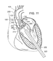
- the THV 250 is located at the aortic annulus and between the native aortic leaflets.
- FIG. 11 also illustrates retraction of the introducer sheath 220 from its more distal position in FIG. 10 .
- Radiopaque markers may be provided on the distal end of the introducer sheath 220 to more accurately determine its position relative to the valve 210 and balloon 232 .
- FIGS. 12-13 show the front third of the support stent 10 and the front of the THV 250 , but do not show the portions of the native heart valve that would be secured by the front of the support stent 10 . It is to be understood, however, that a corresponding leaflet of the native heart valve would be secured between the support stent 10 and the THV 250 .
- the precise positioning of the THV 250 may be accomplished by locating radiopaque markers on its distal and proximal ends.
- the surgeon can adjust the position of the valve 250 by actuating a steering or deflecting mechanism within the balloon catheter 230 .
- the rotational orientation of the valve 250 can be adjusted relative to the cusps and commissures of the native aortic valve by twisting the balloon catheter 230 from its proximal end and observing specific markers on the valve (or balloon catheter) under fluoroscopy.
- One of the coronary ostia 280 opening into one of the sinuses of the ascending aorta is also shown in FIG. 11 , and those of skill in the art will understand that it is important not to occlude the two coronary ostia with the prosthetic valve 250 .
- FIG. 11 shows the THV 250 in its contracted or unexpanded state crimped around the balloon 232 .
- the balloon 232 is expanded to engage the support stent 10 as seen in FIG. 12 .
- the engagement of the support stent 10 to the exterior of the THV 250 pinches the leaflets of the aortic valve between the support stent and the THV 250 , and thereby secures the THV within the annulus of the aortic valve.
- the inner catheter 118 of the delivery system 100 can be retracted, thereby causing the prongs of the inner fork 138 to become disengaged from the retaining arms of the support stent 10 .
- the prongs of the inner fork 138 can be disengaged from the retaining arms by retracting the stent delivery catheter 108 .
- the delivery system 100 can be retracted from the aortic arch and removed from the patient.
- valve 250 can take a variety of different forms and may comprise an expandable stent portion that supports a valve structure.
- the stent portion desirably has sufficient radial strength to hold the valve at the treatment site and to securely engage the support stent 10 . Additional details regarding balloon expandable valve embodiments that can be used in connection with the disclosed technology are described in U.S. Pat. Nos. 6,730,118 and 6,893,460, both of which are hereby expressly incorporated herein by reference.
- the balloon 232 is deflated, and the entire delivery system including the balloon catheter 230 is withdrawn over the guidewire 224 .
- the guidewire 224 can then be withdrawn, followed by the introducer sheath 220 .
- purse-string sutures 260 at the left ventricular apex can be cinched tight and tied to close the puncture.
- FIGS. 14-16 shows another embodiment of a support stent or frame 310 that can be used to help secure a THV into the interior of a native heart valve, such as the aortic valve.
- FIG. 14 is a perspective view of the support stent 310
- FIG. 15 is a top view of the support stent 310
- FIG. 16 is a side view of the support stent 310 .
- support stent 310 has a generally annular or torroidal body formed from a suitable shape-memory metal or alloy, such as spring steel, Elgiloy®, or Nitinol.
- the support stent 310 is also radially compressible to a smaller profile and can self expand when deployed into its functional size and shape. In other embodiments, however, the support stent 310 is not self expanding.
- the support stent 310 includes a generally cylindrical main body portion 320 and a rim portion 330 .
- the support stent 310 can be a mesh structure, which can be formed, for example, from multiple elements in which approximately half of the elements are angled in a first direction and approximately half of the elements are angled in a second direction, thereby creating a criss-cross or diamond-shaped pattern.
- the rim portion 330 has a greater diameter than the main body portion 320 and is formed as an extension at a bottom region of the main body portion that is folded outwardly from the main body portion and back toward a top region of the main body portion.
- the rim portion 330 thus forms a U-shaped rim or lip around the bottom region of the support stent 310 .
- the rim portion 330 is designed to have a diameter that is slightly larger than the walls of the aortic arch that surround the aortic valve.
- the main body portion 320 defines an interior into which an expandable THV can be expanded and which further engages the native leaflets of the aortic valve.
- the main body portion 320 operates in the same manner as the support stent 10 described above and illustrated in FIGS. 1-12 , whereas the rim portion 330 of the support stent 310 operates to secure the support stent in place by engaging the walls of the aorta that surround the aortic valve.
- the support stent 310 further includes retaining arms 321 , 322 , 323 that can be used to help position and deploy the support stent 310 into its proper location relative to the native aortic valve.
- the retaining arms 321 , 322 , 323 can have respective apertures 326 , 327 , 328 .
- the retaining arms 321 , 322 , 323 are constructed and function in a similar manner as retaining arms 21 , 23 , 25 described above in the embodiment illustrated in FIGS. 1-12 .
- FIGS. 17-18 illustrate one exemplary procedure for deploying the support stent 310 and securing a THV 340 within an interior of the support stent.
- FIGS. 17-18 are cross-sectional views through the left side of a patient's heart showing the acts performed in delivering the support stent 310 through the aortic arch to the aortic valve.
- certain details concerning the delivery system of the THV 340 are omitted. Additional details and alternative embodiments of the delivery system for the THV 340 that may be used with the support stent described herein are discussed in U.S. Patent Application Publication No. 2008/0065011 (U.S. application Ser. No. 11/852,977) and U.S. Patent Application Publication No. 2007/0005131 (U.S. application Ser. No. 11/152,288), which are hereby expressly incorporated herein by reference.
- FIG. 17 shows an outer catheter 352 (which can be a guide catheter) of a delivery system 350 as it is advanced through the aortic arch 302 into a position near the surface of the outflow side of the aortic valve 304 .
- the delivery system 350 can be inserted through the femoral artery of the patient and advanced into the aorta in the retrograde direction.
- FIG. 17 also shows a stent delivery catheter 354 , an inner catheter 356 , and the support stent 310 . Also seen in FIG. 17 are the outer fork 360 and the inner fork 362 , which couple the support stent 310 to the distal ends of the stent delivery catheter 354 and the inner catheter 356 , respectively.
- FIG. 17 shows the support stent 310 after it has been advanced through the distal end of the guide catheter 352 and assumes its final, uncompressed shape in a position adjacent to the aortic valve 304 .
- FIGS. 17-18 do not show the entire front side of the support stent 310 or the corresponding valve leaflet that would be secured by the front side of the support stent 310 . It is to be understood, however, that in practice the entire support stent 310 would exist and engage a corresponding leaflet of the native heart valve.
- the support stent 310 can be positioned adjacent to the aortic valve 304 so that the rim portion 330 of the support stent engages the walls surrounding the aortic valve 304 and exerts an outward force against those walls, thereby securing the support stent 310 within the aorta.
- This positioning can be achieved, for example, by advancing the guide catheter 352 to a position directly adjacent the aortic valve 304 while the stent delivery catheter 354 and the inner catheter 356 are undeployed and while the support stent 310 remains in its compressed state.
- the guide catheter 352 can then be retracted while the stent delivery catheter 354 and the inner catheter 356 are held in place, thereby allowing the support stent 310 to expand toward its natural shape.
- the position of the guide catheter 352 and the support stent 310 relative to the aortic valve 304 can be monitored using radiopaque markers and fluoroscopy, or using other imaging systems such as transesophageal echo, transthoracic echo, IVUS, or an injectable dye that is radiopaque.
- the prongs of the inner fork 362 can be disengaged from the corresponding apertures of the retaining arms of the support stent 310 .
- the inner catheter 356 can be retracted into the interior of the stent delivery catheter 354 , thereby releasing the support stent 310 from the outer fork 360 and the inner fork 362 .
- the delivery system 350 can then be retracted from the aorta and removed from the patient's body.
- a THV (such as any of the THVs discussed above) can be introduced.
- a delivery system having a delivery catheter that is advanced through the patient's aorta can be used to deliver the THV.
- a transfemoral approach can be used.
- any of the exemplary systems and methods described in U.S. Patent Application Publication No. 2008/0065011 (U.S. application Ser. No. 11/852,977) or U.S. Patent Application Publication No. 2007/0005131 (U.S. application Ser. No. 11/152,288) can be used with the support stent 310 .
- the transapical approach shown in FIGS. 7-13 can be used.
- FIG. 18 shows delivery system 380 comprising an outer catheter 382 (which can be a guide catheter) and a balloon catheter 390 extending through the guide catheter.
- the balloon catheter 390 has a balloon at its distal end on which the THV is mounted.
- the delivery system 380 can be inserted through the femoral artery of the patient and advanced into the aorta in the retrograde direction.
- FIG. 18 further shows a guidewire 392 that has been first inserted into the patient's vasculature and advanced into the left ventricle. The delivery system can then be inserted into the body and advanced over the guidewire 392 until the THV is positioned within the interior of the aortic valve.
- the THV is not only in the interior of the aortic valve 304 but also in the interior of the main body portion of the support stent 310 .
- FIG. 18 shows the THV 340 in its contracted (or unexpanded) state crimped around the balloon portion of the balloon catheter 390 .
- the balloon of the balloon catheter 390 can be expanded such that the THV 340 expands and urges the native leaflets of the aortic valve against the support stent 310 , thereby securing the THV within the annulus of the aortic valve.
- the balloon of the balloon catheter 390 is deflated, and the entire delivery system 380 including the balloon catheter is withdrawn over the guidewire 392 . The guidewire 392 can then be withdrawn.
- a support stent and THV are delivered surgically to the desired heart valve (e.g., in an open-heart surgical procedure).
- the support stent and THV are delivered surgically, non-compressible support stents and/or THVs are used.
- Aortic insufficiency can cause dilatation of the ascending aorta, causing aneurisms, as well as the aortic annulus.
- embodiments of the present invention provide for anchoring of a deflector that directs blood away from the aneurysm while at the same time treating the insufficient heart valve.
- a medical device 410 for treating AI includes a support structure 412 , a stent 414 , a prosthetic valve 416 and a deflector 418 .
- the support structure 412 is configured, similar or the same as the support structures described hereinabove, to cooperate with the prosthetic valve 416 to pinch the native valve therebetween and provide an anchor for the stent 414 which extends into the aorta and supports the deflector 418 which is positioned to abate blood flow against the aneurysm.
- the support structure 412 (stent or frame) includes, for example in FIG. 19 , peaks 420 , 422 , 424 and valleys 430 , 432 , 434 and retaining arms 421 , 423 , 425 defining apertures 426 , 427 , 428 . Similar to the other embodiments of the support structures disclosed herein, a range of variations are possible for anchoring the both the stent 414 and the prosthetic valve 416 and the deflector 418 .
- the shape of the support stent or frame 410 can vary from implementation to implementation.
- the support stent is not sinusoidal or otherwise shaped in the z-plane.
- the support stent is shaped as a cylindrical band or sleeve.
- the support stent or frame can be any shape that defines an interior through which a THV can be inserted, thereby causing the native leaflets of the aortic valve (or other heart valve) to be pinched or securely held between the support stent and the THV.
- the support stent can have a more complex structure.
- the support stent illustrated in FIG. 19 is formed from a single annular member (or strut), the support stent can comprise multiple annular elements that interlock or are otherwise connected to one another (e.g., via multiple longitudinal members).
- the prosthetic valve 416 of the embodiment illustrated in FIG. 19 is a THV that is similar to the one illustrated in FIG. 1 .
- THV THV
- this particular usage is for illustrative purposes only and should not be construed as limiting.
- embodiments of the disclosed support structure can be used to secure a wide variety of THVs delivered through a variety of mechanisms (e.g., self-expanding heart valves, other balloon-expanding heart valves, and the like).
- any of the embodiments described in U.S. Pat. No. 6,730,118 can be used with embodiments of the disclosed support structure.
- the stent 414 is a scaffold that is coupled to the support structure 412 and extends from the support structure into the aorta (and over the insufficient portions of the aorta).
- the stent 414 has a proximal end 430 , a distal end 432 , and a plurality of interconnected struts 434 defining a plurality of cells 436 .
- the proximal (with respect to the heart) end 430 of the stent 414 is connected or coupled to the support structure 412 by being formed therewith or attachment by wires or other supports.
- the support structure 412 and stent 414 including the plurality of interconnected struts 434 , may be laser cut from a single metal tube.
- coupling may also be by assembly after separate formation, include assembly in vivo as each portion of the medical device 410 is delivered.
- the body of the stent 414 that is formed by the interconnected struts 434 that define between them the cells 436 .
- the interconnected struts 434 are formed to promote flexibility and facilitate delivery through tortuous paths and extension over the aortic arch.
- the strut pattern may be as shown (as a flattened portion of a laser-cut blank prior to expansion) in FIG. 20 and include a plurality of rings 438 formed by sinusoidal struts connected end-to-end, wherein the rings are connected by a plurality of angled, flexible connectors 440 .
- the rings 438 may be formed to have variable lengths and the connectors 440 selectively located to promote directional preferences in flexibility and/or variations in cell sizes between them.
- LIFESTENT manufactured by C.R. BARD, INC. which has a multi-dimensional helical structure that facilitates its use in tortuous paths of peripheral vasculature. Aspects of the LIFESTENT are described in U.S. Pat. No. 6,878,162 entitled “Helical Stent Having Improved Flexibility and Expandability” by Bales et al.
- the stent 414 when extending along the aortic arch, has a tightly curved configuration with an external, long curvature 442 and an internal curvature 444 .
- the cell sizes may be larger to allow for the longer path length.
- These cell sizes may be programmed into the stent by selective cutting and formation of the struts and cells and/or may appear due to the mechanical application of insertion and delivery into the aortic arch.
- the internal curvature 444 may be programmed through selection of the strut structure and/or due to delivery.
- the stent 414 may include structure that facilitates engagement, frictional or mechanical, of the surrounding lumen (e.g., the aorta) where the lumen is in adjacent contact with the stent.
- the struts 434 and cells 436 may have a pattern that facilitates frictional engagement, or may have barbs or hooks or micro-anchors or flared portions formed thereon to mechanically engage the lumen and facilitate the support structure 412 's role of securing the medical device 410 .
- the distal end 432 of the stent 414 is positioned within the aortic arch distal the branch (e.g., brachiocephalic, common carotid and left subclavian) arteries extending off of the aorta.
- the distal end 432 may be a termination of the last row of the rings 438 or may include its own retaining arms 446 defining apertures 448 . Use of the retaining arms 446 and apertures 448 enables use of the delivery apparatus 110 shown in FIGS. 3 and 4 and described hereinabove.
- the distal end 432 may also include structure configured to engage the surrounding lumen walls for additional security of the medical device 410 . For example, it may include hooks or barbs or micro anchors.
- the cells 436 may include a relatively large cell structure positioned over and near the branch arteries. This facilitates perfusion of the branch arteries, such as by being located over the branch arteries at the aortic arch or closer to the valve for communication with the coronary arteries.
- the cell structure is relatively large in comparison to the remaining cells configured to support the lumen walls or abate blood flow against aneurysms or further vascular dilatation.
- the cell size may be selected to guard the branch arteries against embolic debris, so as to act as a partial deflector of such debris.
- the length of the device 410 may be enough to extend from the native leaflets, through the sinus of valsalva, into the ascending aorta, over the aortic arch and potentially into the descending aorta.
- the length of the device 410 may be 30 mm to 100 mm or longer.
- the stent 414 may also be tapered, small at the annulus to larger at the ascending aorta, columnar or have ends that are a larger diameter for sealing and anchoring, as shown in FIG. 21 .
- this support structure 412 and stent 414 act like a scaffold or anchoring device for other devices to be deployed inside of it, such as the prosthetic valve 416 , which is delivered and anchored as described above, and one or more deflectors 418 .
- the deflector 418 is a covered stent or graft that is relatively impermeable (e.g. to blood flow and is configured for positioning over an aneurysm in the aortic arch so as to direct blood flow away from the aneurysm.
- the deflector 418 of the embodiment of FIG. 19 includes a deflector stent 450 supporting a tubular graft material 452 extending around the deflector stent.
- the deflector 450 is mounted within the stent 414 as would a graft being fit within a vessel without the stent 414 .
- the deflector 450 may be delivered by a catheter extending retrograde to blood flow within the aorta, or extending from the heart chamber and through the aortic valve, and then expanded (or allowed to expand) once the desired location is reached.
- the stent 414 guards the aneurysm against the expansion pressure of the deflector 418 and the deflector can have a much smaller expanded diameter than the aneurysm and still is assured of a firm anchor.
- Deployment of the medical device 410 of FIG. 19 may include first deploying the support structure 412 and the stent 414 (if they're integrally attached to each other). Then, through the support structure 412 and the sent 414 the THV prosthetic valve 416 is delivered, anchoring it into the proximal end of the device (either the support structure 412 or the stent 414 ). The covered stent or graft deflector 418 is deployed in the stent 414 , covering the area that has the aneurysm and avoiding the branch arteries and associated larger cells 436 of the stent 414 . The deflector 418 would then redirect the pulsating blood away from the aneurysm so as to prevent dissection, and the new valve prosthesis 416 would ensure that correct blood flow is restored.
- the term “deflector” should be construed broadly herein to include any structure that serves to abate (reduce) blood flow against the selected portion of the vessel wall.
- multiple deflectors 418 in the form of grafts or covered stents could be delivered and positioned to address anatomical variations in size and positioning of the aneurysm(s).
- the deflector 418 need not be a tubular structure but could be a sheet or shield of material anchored to one side of the stent 414 .
- the deflector 418 need not be separately attached, but could be a portion of the stent 414 with reduced permeability, such as through a polymeric coating.
- FIG. 21 shows another example wherein the stent 414 is covered with a deflector 418 at the time of delivery.
- FIG. 22 shows another example wherein the stent 414 is covered with a deflector 418 in the form of a balloon 454 .
- the balloon not only deflects blood flow, but also can be inflated so as to expand into and fill the space between the stent 414 and the aneurysm wall.
- Inflation may be by fluid, such as saline wherein the balloon may include a one-way check valve that stops outflow of the saline after detachment of the inflation lumen.
- inflation may be by a polymer or other fluid that sets or cures or thickens and can therefore maintain the fill shape after intervention is complete.
- the expansion forces of the balloon 454 are sufficiently low so as to not further expanded the aneurysm but at the same time cause the balloon to take the shape of the aneurysm space.
- the balloon therefore, may be comprised of a very pliable material such as a silicone that expands under low pressure and/or may even include a woven material.
- a very pliable material such as a silicone that expands under low pressure
- the woven material may have a limit to expansion and will protect the aneurysm from dissection if the woven balloon is fashioned to fit the aneurysm.
- FIG. 23 shows another example wherein the stent 414 is covered with a deflector 418 in the form of a foam sleeve 456 .
- the foam may be an open celled foam or a closed-cell foam that promotes friction with the surrounding lumen at initial implantation. If open celled the blood will in-grow and create a barrier for the blood not to pass along the aortic wall.
- the foam may be configured for up to 300% compression.
- the foam may be configured, such as by being hydrophilic, to absorb and expand in blood and fill the space between the stent 414 and the lumen.
- a skin or impermeable layer can be also applied to the stent 414 or foam sleeve 456 so that the foam does not peel/break off and cause an embolism.
- the skin or impermeable layer inhibits seep of the passing blood through the foam to the aortic wall.
- an inner surface of the foam sleeve 456 may have a relatively impermeable skin (such as a closed cell foam) to promote passage of blood therethrough while the outer surface is open celled and permeable for expansion.
- the foam may also have coagulation properties that promote buildup of clots to help secure the medical device 410 and fill the aneurismal space.
- the foam may include, for example, a flexible ester polyurethane, reticulated open cell, felted foam with a pore size of 80-100 ppi, a density of 5.4-6.3 pcf.
- thick woven sleeves may be used that expand in response to absorbing blood, such as a hydrophilic weave or foam.
- the foam sleeve 456 is crimped down with the stent 414 and then placed in the aorta of the patient.
- the stent 414 expands and maintains its more rigid shape, whereas the foam can also expand and take up the current shape of the aorta.
- the foam advantageously fills the void between the stent 414 and the aneurysm wall, preventing blood (the continued pulse force) from reaching the aneurysm.
- the foam sleeve 456 creates a seal within the aorta forcing blood to be passed through the stent 414 diameter. It also has effective friction or outward forces on the aortic wall so as to restrict movement.
- FIG. 24 shows another example wherein the deflector 418 has an annulus or donut shape, such as a foam or balloon annulus. With its reduced length, the donut may be positioned at the location of the aneurysm, thereby blocking the flow of blood to this particular section of the aortic wall.
- an annulus or donut shape such as a foam or balloon annulus.
- FIG. 25 shows another example including two donut or annulus shaped deflectors 418 on the stent 414 which aid in retention of the device within the aorta.
- donuts may be placed on opposite sides of the aneurysm and seal the aneurysm against blood flow.
- the donuts may be foam, balloons or other expansion members.
- the deflector 418 may include micro anchors attached to the foam or balloon section to aid in retention if the expansion force of the foam or balloon is not suitable in larger aortas.
- the deflector 418 may include mechanical clot facilitators such as wires, coils or springs that fill the space between the stent 414 and the aneurysm walls to promote embolization therebetween.
- mechanical clot facilitators such as wires, coils or springs that fill the space between the stent 414 and the aneurysm walls to promote embolization therebetween.
- FIG. 26 shows another embodiment of the present invention wherein the deflector 418 (in the form of a graft) may include a seal 458 in the form of a slit configured to allow passage into the interior of the stent 414 .
- the seal 458 may include overlapping portions or lips of the graft material that self-seal by closing up after removal of delivery tool.
- the seal may be a valve, such as a duckbill valve.
- the graft 418 with the seal 458 may be used in a during a “trans-aortic” THV implantation wherein the graft is first deployed in a percutaneous delivery.
- the THV is then delivered through the chest wall with a delivery tool (e.g., a catheter) and through a slit in the aorta (aortotomy) and finally through the slit or seal 458 in the graft.
- the slit then seals around the delivery tool to prevent blood loss.
- the THV is expanded into place within the support structure 412 or stent 414 .
- the seal 458 closes when the delivery tool is removed, allowing the aorta to be sutured without blood escaping.
- the graft 418 could be left behind—or it could be retrieved after completion of the procedure.
- Such a seal 458 may be employed in a range of embodiments with the deflector 418 , including the embodiments disclosed herein.
- FIG. 27 shows another embodiment wherein the deflector 418 has an hourglass shape and is constructed of a resilient material that deflects in response to increased blood pressure of a heart beat and adds additional pumping action as the arterial pressure drops.
- the hourglass shape is formed of resilient walls that deflect under pressure and spring back into shape as the pressure drops.
- the walls of the graft may be relatively thick for an increased resiliency and additional pumping action.
- two anchoring stents may be connected by an elastic tube (e.g., made out of silicone).
- One of the anchors is deployed in the STJ (right above the native valve) and the other anchor is deployed on the other end of the aneurysm somewhere in the ascending aorta prior to the branches.
- the elasticity of the tube would aid the heart's pumping action.
- each of the medical devices 410 described herein is capable of a large amount of compression.
- the device 410 including the embodiment of the stent 414 and its foam sleeve 456 , can be compressed or crimped to a diameter that is 8 mm or less. Uncompressed, the diameter may be 50 mm to 90 mm.
- a method of using the medical device 410 disclosed herein includes delivering the support structure 412 to a position on or adjacent to the surface of the outflow side of the native heart valve of the patient, wherein the support structure defines a support-structure interior.
- the expandable prosthetic heart valve 416 is delivered into the native heart valve and into the support-structure interior.
- the expandable prosthetic heart valve 416 is expanded while it is in the support-structure interior and while the support structure is at the position on or adjacent to the surface of the outflow side of the native heart valve. This causes one or more of the native heart valve leaflets to be frictionally secured between the support structure 412 and the expanded prosthetic heart valve 416 .
- the stent 414 which is coupled to the support structure 412 either by co-formation or later attachment, is extended into a vessel (such as the aorta) extending from the native heart valve.
- the deflector 418 is already present on the stent 414 and/or is delivered into and attached to the stent 414 . Blood flow against the vessel is abated by the deflector 418 .
- the method also may include delivering the stent 414 (or portions thereof) to a position adjacent the support structure 412 and coupling it to the support structure prior to extending the stent into the vessel.
- the deflector 418 may be delivered to a support position on the stent 414 and coupled to the stent in vivo.
- the portions could be individually delivered and coupled to each other in vivo.
- the method includes avoiding arteries extending from the vessel when positioning the deflector.
- the method may include expanding the deflector 418 to fill at least a portion of the space between an external surface of the stent 414 and the vessel.
Abstract
Description
- This application claims the benefit of U.S. Provisional Application No. 61/491,655 filed May 31, 2011 which is hereby incorporated herein by reference.
- This application relates to methods, systems, and apparatus for safely replacing native heart valves with prosthetic heart valves.
- Prosthetic heart valves have been used for many years to treat cardiac valvular disorders. The native heart valves (such as the aortic, pulmonary, tricuspid and mitral valves) serve critical functions in assuring the forward flow of an adequate supply of blood through the cardiovascular system. These heart valves can be rendered less effective by congenital, inflammatory, or infectious conditions. Such conditions can eventually lead to serious cardiovascular compromise or death. For many years the definitive treatment for such disorders was the surgical repair or replacement of the valve during open heart surgery.
- More recently a transvascular technique has been developed for introducing and implanting a prosthetic heart valve using a flexible catheter in a manner that is less invasive than open heart surgery. In this technique, a prosthetic valve is mounted in a crimped state on the end portion of a flexible catheter and advanced through a blood vessel of the patient until the valve reaches the implantation site. The valve at the catheter tip is then expanded to its functional size at the site of the defective native valve, such as by inflating a balloon on which the valve is mounted. Alternatively, the valve can have a resilient, self-expanding stent or frame that expands the valve to its functional size when it is advanced from a delivery sheath at the distal end of the catheter.
- Balloon-expandable valves are commonly used for treating heart valve stenosis, a condition in which the leaflets of a valve (e.g., an aortic valve) become hardened with calcium. The hardened leaflets provide a good support structure on which the valve can be anchored within the valve annulus. Further, the catheter balloon can apply sufficient expanding force to anchor the frame of the prosthetic valve to the surrounding calcified tissue. There are several heart conditions, however, that do not involve hardened valve leaflets but which are still desirably treated by valve replacement. For example, aortic insufficiency (or aortic regurgitation) occurs when an aortic valve does not close properly, allowing blood to flow back into the left ventricle. One cause for aortic insufficiency is a dilated aortic annulus, which prevents the aortic valve from closing tightly. In such cases, the leaflets are usually too soft to provide sufficient support for a balloon-expandable prosthetic valve. Additionally, the diameter of the aortic annulus may continue to vary over time, making it dangerous to install a prosthetic valve that is not reliably secured in the valve annulus. Mitral insufficiency (or mitral regurgitation) involves these same conditions but affects the mitral valve.
- Self-expanding prosthetic valves are sometimes used for replacing defective native valves with non-calcified leaflets. Self-expanding prosthetic valves, however, suffer from a number of significant drawbacks. For example, once a self-expanding prosthetic valve is placed within the patient's defective heart valve (e.g., the aorta or mitral valve), it continues to exert an outward force on the valve annulus. This continuous outward pressure can cause the valve annulus to dilate further, exacerbating the condition the valve was intended to treat. Additionally, when implanting a self-expanding valve, the outward biasing force of the valve's frame tends to cause the valve to be ejected very quickly from the distal end of a delivery sheath.
- The size of the prosthetic valve to be implanted into a patient can also be problematic when treating aortic or mitral insufficiency. Specifically, the size of a prosthetic valve used to treat aortic or mitral insufficiency is typically larger than a prosthetic valve used to treat aortic or mitral stenosis. This larger valve size makes the delivery procedure much more difficult.
- Accordingly, there exists a need for improved methods, systems, and apparatus for delivering expandable prosthetic heart valves (e.g., balloon-expandable prosthetic valves). Embodiments of the methods, systems, and apparatus desirably can be used to replace native heart valves that do not have calcified leaflets (e.g., aortic valves suffering from aortic insufficiency). Furthermore, embodiments of the methods, systems, and apparatus desirably enable precise and controlled delivery of the prosthetic valves.
- A medical device for treating aortic insufficiency (and associated aneurysms or defects of any other vessel associated with a valve) includes a support structure, a stent, a prosthetic valve and a deflector. Generally, the support structure is configured to cooperate with the prosthetic valve to pinch the native valve therebetween and provide an anchor for the stent which extends into the aorta and supports the deflector which is positioned to abate blood flow against the aneurysm.
- In one embodiment, the medical device is for use in a heart having a native valve and a vessel extending from the native heart valve. The medical device includes a support structure, a stent, a prosthetic valve and a deflector. The support structure is configured to engage at least a portion of the native heart valve. The stent is configured to couple to the support structure and extend from the support structure into the vessel. The prosthetic valve is configured to couple to at least one of the stent or the support structure. The deflector is configured to be supported by the stent and abate blood flow against the vessel.
- The support structure may include a stent configured to extend around the native heart valve. And, the support structure is configured to receive and support therein the prosthetic heart valve. In this configuration, the prosthetic heart valve is expandable within an interior of the support structure. This causes one or more of the native leaflets of the native heart valve to be frictionally secured between the support structure and the expanded prosthetic heart valve.
- In another aspect, the stent may include openings configured for placement adjacent arteries extending from the vessel. The openings may include large cells that are relatively larger than small cells defined on the rest of the stent. And, the deflector may be configured to extend over at least some of the small cells and not over the larger cells.
- The deflector may be an impermeable graft. The deflector may also be configured to expand to fill at least of a portion of a space defined between an external surface of the stent and the vessel. For example, the deflector may include a balloon or a foam. The foam may be open celled and hydrophilic to promote absorption of blood and tissue ingrowth to further secure the medical device and protect the aneurism. Internally, the foam deflector may include an impermeable skin to facilitate passage of blood flow through the medical device.
- Generally, embodiments of the medical device (including those with foam deflectors) are configured for a large amount of compression into a compressed diameter. For example, the compressed diameter may be 8 mm or less from an uncompressed diameter of 50 mm to 90 mm.
- In another embodiment, the deflector includes one or more annuluses configured to extend around the stent and expand into contact with the internal lumen of the surrounding vessel.
- In another embodiment, the deflectors include one or more anchors. Also, the deflector may include a seal configured to allow selective passage through the deflector. Such a seal may be a duckbill valve or may include overlapping portions of a graft material.
- In another embodiment, the medical device may include a plurality of mechanical clot facilitators to promote embolic debris formation between the deflector and the vessel wall.
- In another embodiment, the stent may include a plurality of portions that are configured to be delivered separately and interconnected in vivo to form the stent.
- Also, the deflector may be configured to abate blood flow by blocking embolic debris from branch arteries.
- In another embodiment, the deflector is configured to resiliently respond to blood flow. For example, the deflector may define a lumen with a resilient wall structure. The resilient wall structure has an hourglass shape and deflectable walls.
- In another embodiment, the invention includes a medical device for use in a heart having a heart valve and a vessel associated with the heart valve. The medical device includes a support structure configured to engage the heart valve. A stent of the medical device is configured to couple to the support structure and extend from the support structure into the vessel. And, a foam deflector is configured to be supported by the stent and abate blood flow against he vessel.
- In one aspect, the foam has a relatively impermeable skin. In another aspect the foam is hydrophilic.
- Also, the support, stent and foam may be configured for a large amount of compression into a compressed diameter. For example, the compressed diameter may be 8 mm or less and the uncompressed diameter is 50 mm to 90 mm. The length of the medical device may be 100 mm or more.
- The deflector may also include a seal configured to allow selective passage into the vessel, such as wherein the seal has overlapping portions of graft material or incorporates a duckbill valve therein.
-
FIG. 1 is a perspective view of an exemplary embodiment of a support structure according to the disclosed technology. -
FIG. 2 is a cross-sectional view of a native aortic valve with the support structure ofFIG. 1 positioned therein. -
FIGS. 3 and 4 are perspective views of an exemplary delivery system for the support structure ofFIG. 1 . In particular,FIG. 3 shows the delivery system before the support structure is deployed, andFIG. 4 shows the delivery system after the support structure is deployed. -
FIG. 5 is an exploded view of the components of the exemplary delivery system shown inFIGS. 3 and 4 . -
FIG. 6 is a zoomed-in perspective view showing the mechanism for releasably connecting the support structure to the exemplary delivery system ofFIGS. 3 and 4 . -
FIGS. 7 and 8 are cross-sectional views of a patient's heart illustrating how the delivery system ofFIGS. 3 and 4 can operate to deploy the support structure ofFIG. 1 to a desired position on the patient's aortic valve. -
FIGS. 9-13 are cross-sectional views of a patient's heart illustrating how an exemplary transcatheter heart valve (“THV”) can be deployed to the patient's aortic valve and frictionally secured to the native leaflets using the support structure ofFIG. 1 . -
FIG. 14 is a perspective view of another exemplary embodiment of a support structure according to the disclosed technology. -
FIG. 15 is a top view of the support structure embodiment shown inFIG. 14 . -
FIG. 16 is a side view of the support structure embodiment shown inFIG. 14 . -
FIG. 17 is a cross-sectional view of a patient's heart illustrating how a delivery system can operate to deploy the support structure ofFIG. 14 to a desired position on the patient's aortic valve. -
FIG. 18 is a cross-sectional view of a patient's heart illustrating how an exemplary THV can be deployed through the aortic arch and into the patient's aortic valve, where it can be frictionally secured to the native leaflets using the support structure ofFIG. 14 . -
FIG. 19 is a cross-sectional view of a patient's heart showing a medical device of another embodiment of the present invention including a stent that supports a deflector for treating vessel aneurysms. -
FIG. 20 is a plan view of a portion of a scaffold of the stent ofFIG. 19 . -
FIG. 21 is a cross-sectional view of a patient's heart showing a medical device of another embodiment wherein a stent is covered with a deflector and is tapered. -
FIG. 22 is a cross-sectional view of a patient's heart showing a medical device of another embodiment wherein a stent is covered with a balloon configured to fill an aneurysm in the insufficient vessel. -
FIG. 23 is a cross-sectional view of a medical device of another embodiment wherein a stent is covered with a foam sleeve deflector. -
FIG. 24 is a cross-sectional view of a patient's heart showing a medical device of another embodiment including a deflector with an annulus shape. -
FIG. 25 is a cross-sectional view of a patient's heart showing a medical device of another embodiment including a pair of annulus shaped deflectors. -
FIG. 26 is a cross-sectional view of a patient's heart showing a medical device of another embodiment including a deflector with a seal allowing passage of THV delivery device. -
FIG. 27 is cross-sectional view of a patient's heart showing a medical device of another embodiment including a deflector with a resilient hourglass shape configured to resiliently aid in the pumping of blood. -
FIG. 28 is a cross-sectional view of a patient's heart showing a medical device of another embodiment including anchors on a foam deflector supported by a stent. - General Considerations
- Disclosed below are representative embodiments of a support structure (sometimes referred to as a “support stent,” “support frame,” “support band,” or “support loop”) that can be used to secure a prosthetic heart valve within a native heart valve. For illustrative purposes, embodiments of the support structure are described as being used to secure a transcatheter heart valve (“THV”) in the aortic valve or the mitral valve of a heart. It should be understood that the disclosed support structure and THV can be configured for use with any other heart valve as well. Also disclosed herein are exemplary methods and systems for deploying the support structure and corresponding THV. Although the exemplary methods and systems are mainly described in connection with replacing an aortic or mitral valve, it should be understood that the disclosed methods and systems can be adapted to deliver a support structure and THV to any heart valve.
- For illustrative purposes, certain embodiments of the support structure are described as being used in connection with embodiments of the balloon-expandable THV described in U.S. Patent Application Publication No. 2007/0112422 (U.S. application Ser. No. 11/280,063), which is hereby expressly incorporated herein by reference. It should be understood, however, that this particular usage is for illustrative purposes only and should not be construed as limiting. Instead, embodiments of the disclosed support structure can be used to secure a wide variety of THVs delivered through a variety of mechanisms (e.g., self-expanding heart valves, other balloon-expanding heart valves, and the like). For instance, any of the embodiments described in U.S. Pat. No. 6,730,118 can be used with embodiments of the disclosed support structure. U.S. Pat. No. 6,730,118 is hereby expressly incorporated herein by reference.
- The described methods, systems, and apparatus should not be construed as limiting in any way. Instead, the present disclosure is directed toward all novel and nonobvious features and aspects of the various disclosed embodiments, alone and in various combinations and sub-combinations with one another. The disclosed methods, systems, and apparatus are not limited to any specific aspect, feature, or combination thereof, nor do the disclosed methods, systems, and apparatus require that any one or more specific advantages be present or problems be solved.
- Although the operations of some of the disclosed methods are described in a particular, sequential order for convenient presentation, it should be understood that this manner of description encompasses rearrangement, unless a particular ordering is required by specific language set forth below. For example, operations described sequentially may in some cases be rearranged or performed concurrently. Moreover, for the sake of simplicity, the attached figures may not show the various ways in which the disclosed methods, systems, and apparatus can be used in conjunction with other systems, methods, and apparatus.
- Exemplary Embodiments for Replacing Aortic Valves
-
FIG. 1 is a perspective view showing an exemplary embodiment of a support stent orframe 10.Support stent 10 has a generally annular or torroidal body formed from a suitable shape-memory metal or alloy, such as spring steel, Elgiloy®, or Nitinol. Desirably, the material from which thesupport stent 10 is fabricated allows the support stent to automatically expand to its functional size and shape when deployed but also allows the support stent to be radially compressed to a smaller profile for delivery through the patient's vasculature. In other embodiments, however, the stent is not self expanding. In these embodiments, and as more fully explained below, other mechanisms for expanding the stent can be used (e.g., a balloon catheter). - In the illustrated embodiment, the projection of the
support stent 10 onto an x-y plane has a generally annular or torroidal shape. The illustratedsupport stent 10 further defines a number of peaks and valleys (or crests and troughs) along its circumference. For example, thesupport stent 10 is sinusoidally shaped in the z direction. In other embodiments, thesupport stent 10 is shaped differently in the z direction (e.g., sawtooth-shaped, ringlet-shaped, square-wave shaped, or otherwise shaped to include peaks and valleys). - The illustrated
support stent 10 includes threepeaks valleys peaks valleys valleys support stent 10 onto an x-y plane forms a closed shape having a variable radius (e.g., a starfish shape). - The size of the
support stent 10 can vary from implementation to implementation. In particular embodiments, thesupport stent 10 is sized such that the support stent can be positioned within the aorta of a patient at a location adjacent to the aortic valve, thereby circumscribing the aortic valve. Furthermore, in order to frictionally secure a prosthetic heart valve in its interior, certain embodiments of thesupport stent 10 have a diameter that is equal to or smaller than the diameter of the prosthetic heart valve when fully expanded. In particular embodiments, for instance, the support stent can have an inner or outer diameter between 10 and 50 mm (e.g., between 17 and 28 mm) and a height between 5 and 35 mm (e.g., between 8 and 18 mm). Furthermore, the thickness of the annular body of thesupport stent 10 may vary from embodiment to embodiment, but in certain embodiments is between 0.3 and 1.2 mm. -
FIG. 2 is a perspective view of theexemplary support stent 10 positioned on the surface of an outflow side of a native aortic valve and further illustrates the shape of the support stent. In particular, it can be seen fromFIG. 2 that thevalleys support stent 10 are shaped so that they can be placed adjacent tocommissures native leaflets peaks leaflets leaflets peaks commissures native leaflets leaflets support stent 10 can be positioned in any other orientation within the aortic valve as well. - It should be understood that the shape of the support stent or
frame 10 can vary from implementation to implementation. For example, in some embodiments, the support stent is not sinusoidal or otherwise shaped in the z-plane. In other embodiments, the support stent is shaped as a cylindrical band or sleeve. In general, the support stent or frame can be any shape that defines an interior through which a THV can be inserted, thereby causing the native leaflets of the aortic valve (or other heart valve) to be pinched or securely held between the support stent and the THV. Furthermore, the support stent can have a more complex structure. For example, although the support stent illustrated inFIGS. 1 and 2 is formed from a single annular member (or strut), the support stent can comprise multiple annular elements that interlock or are otherwise connected to one another (e.g., via multiple longitudinal members). - Returning to
FIG. 1 , the illustratedsupport stent 10 also include retainingarms support stent 10 into its proper location relative to the native aortic valve. The retainingarms respective apertures support stent 10 using the retainingarms support stent 10 can also have one or more barbs located on its surface. Such barbs allow thesupport stent 10 to be more securely affixed to the tissue surrounding the stent or the leaflets of the aorta. -
FIGS. 3 and 4 are side views of the distal end portion of anexemplary delivery apparatus 100 for delivering thesupport stent 10 to its location adjacent the native aortic valve through a patient's vasculature. In particular,FIG. 3 shows the delivery apparatus when thesupport stent 10 is in a compressed, predeployed state, whereasFIG. 4 shows the delivery apparatus when thesupport stent 10 is in a decompressed, deployed state. Thedelivery apparatus 100 comprises aguide catheter 102 having anelongated shaft 104, whosedistal end 105 is open in the illustrated embodiment. In other embodiments, thedistal end 105 of theguide catheter 102 can be tapered into a conical shape comprising multiple “flaps” forming a protective nose cone that can be urged apart when thesupport stent 10 and any interior catheters are advanced therethrough. Furthermore, for illustrative purposes, theguide catheter 102 is shown as being partially cut away, thus revealing the catheters in its interior. - A proximal end (not shown) of the
guide catheter 102 is connected to a handle of thedelivery apparatus 100. During delivery of a support stent, the handle can be used by a surgeon to advance and retract the delivery apparatus through the patient's vasculature. In a particular use, thedelivery apparatus 100 is advanced through the aortic arch of a patient's heart in the retrograde direction after having been percutaneously inserted through the femoral artery. The guide catheter can be configured to be selectively steerable or bendable to facilitate advancement of thedelivery system 100 through the patient's vasculature. An exemplary steerable guide catheter as can be used in embodiments of the disclosed technology is described in detail in U.S. Patent Application Publication No. 2007/0005131 (U.S. patent application Ser. No. 11/152,288), which is hereby expressly incorporated herein by reference. - The
delivery apparatus 100 also includes astent delivery catheter 108 positioned in the interior of theguide catheter 102. Thestent delivery catheter 108 has an elongatedshaft 110 and anouter fork 140 connected to a distal end portion of theshaft 110. Theshaft 110 of thestent delivery catheter 108 can be configured to be moveable axially relative to theshaft 104 of theguide catheter 102. Furthermore, theshaft 110 of thestent delivery catheter 108 can be sized so that its exterior wall is adjacent to or in contact with the inner wall of theshaft 104 of theguide catheter 102. - The
delivery apparatus 100 can also include aninner catheter 118 positioned in the interior of the stent delivercatheter 108. Theinner catheter 118 can have anelongated shaft 120 and aninner fork 138 secured to the distal end portion of theshaft 120. Theshaft 120 of theinner catheter 118 can be configured to be moveable axially relative to theshaft 104 of theguide catheter 102 and relative to theshaft 110 of thestent delivery catheter 108. Furthermore, theshaft 120 of theinner catheter 118 can be sized so that its exterior wall is adjacent to or in contact with the inner wall of theshaft 110 of thestent delivery catheter 108. A guide wire (not shown) can be inserted into the interior of theinner catheter 118. The guide wire can be used, for example, to help ensure proper advancement of theguide catheter 102 and its interior catheters through the vasculature of a patient. - As best shown in
FIG. 5 , a stent retaining mechanism is formed from theinner fork 138 attached to the distal end portion of theshaft 120 of theinner catheter 118 and theouter fork 140 attached to the distal end portion of theshaft 110 of thestent delivery catheter 108. Theinner fork 138 includes a plurality of flexibleinner prongs arms support stent 10, and ahead portion 144 at its proximal end. Theouter fork 140 includes a plurality of flexibleouter prongs arms stent 10, and ahead portion 148 at its proximal end. The distal end portions of theouter prongs respective apertures arms -
FIG. 6 is a zoomed-in view of one of the retainingarms outer fork 140 and theinner fork 138. In this example, retainingarm 21 is shown, though it should be understood that the retaining mechanism is similarly formed for the retainingarms outer prong 145 is formed with theaperture 155. When assembled, the retainingarm 21 of the stent is inserted through theaperture 155 of theprong 145 of the outer fork and theprong 141 of the inner fork is inserted through theaperture 26 of the retainingarm 21 so as to retain the retainingarm 21 in theaperture 155. - Retracting the
inner prong 141 proximally (in the direction of arrow 152) to remove the prong from theaperture 26 allows the retainingarm 21 to be removed from theaperture 155, effectively releasing the retaining arm from the retaining mechanism. For instance, theouter prong 145 and the retainingarm 21 can be formed such that when theinner prong 141 is withdrawn from theaperture 26, theouter prong 145 flexes radially inward (downward inFIG. 7 ) and/or the retainingarm 21 of the support stent flexes radially outward (upward inFIG. 7 ), thereby causing the retainingarm 21 to be removed from theaperture 155. In this manner, the retaining mechanism formed by theinner fork 138 and theouter fork 140 create a releasable connection with thesupport stent 10 that is secure enough to retain the support stent to thestent delivery catheter 108 and to allow the user to adjust the position of the support stent after it is deployed. When thesupport stent 10 is positioned at the desired location adjacent to the leaflets of the aortic valve, the connection between the support stent and the retaining mechanism can be released by retracting theinner fork 138 relative to theouter fork 140, as further described below. In other embodiments, the function of the inner fork and the outer fork can be reversed. For example, the prongs of the inner fork can be formed with apertures sized to receive the corresponding retaining arms of the support stent and the prongs of the outer fork can be inserted through the apertures of the retaining arms when the retaining arms are placed through the apertures of the prongs of the inner fork. - As best shown in the exploded view in
FIG. 5 , thehead portion 144 of the inner fork can be connected to the distal end portion of theshaft 120 of theinner catheter 118. In the illustrated embodiment, for example, thehead portion 144 of the inner fork is formed with a plurality of angularly spaced, inwardly biased retainingflanges 154. An end piece of theshaft 120 can be formed as a cylindrical shaft having anannular groove 121. On the distal side of theannular groove 121, theshaft 120 can have acollar 122 with an outer diameter that is slightly greater than the diameter defined by the inner free ends of theflanges 154. Thus, theinner fork 138 can be secured to the end piece by insertinghead portion 144 of the inner fork onto the end piece of theshaft 120 until theflanges 154 flex inwardly into theannular groove 121 adjacent thecollar 122, thereby forming a snap-fit connection between thehead portion 144 and theshaft 120. Thehead portion 144 can have a proximal end that engages an annular shoulder 123 of theshaft 120 that is slightly larger in diameter so as to prevent the head portion from sliding longitudinally along theshaft 120 in the proximal direction. - The
head portion 148 of the outer fork can be secured to a distal end portion of theshaft 110 of thestent delivery catheter 108 in a similar manner. As shown inFIG. 5 , thehead portion 148 can be formed with a plurality of angularly spaced, inwardly biased retainingflanges 155. An end piece of theshaft 110 can be formed as a cylindrical shaft having anannular groove 111. On the distal side of theannular groove 111, theshaft 110 can have acollar 112 with an outer diameter that is slightly greater than the diameter defined by the free ends of theflanges 155. Thus, theouter fork 140 can be secured to the end piece of theshaft 110 by inserting theshaft 110 onto thehead portion 148 until the flanges flex inwardly into thegroove 111, thereby forming a snap-fit connection between thehead portion 148 and theshaft 110. Thehead portion 148 can have a proximal end that engages an annular shoulder 123 of theshaft 110 that is slightly larger so as to prevent the head portion from sliding longitudinally along theshaft 110 in the proximal direction. - In
FIG. 3 , thesupport stent 10 is shown in a radially compressed state in the interior of theelongated shaft 104 of theguide catheter 102. In the radially compressed state, the distance along the z axis between a peak and an adjacent valley of the support stent is greater than the distance along the z axis between the peak and the adjacent valley when the support stent is in it uncompressed state. The distal end portion of theshaft 104 can also be referred to as a delivery sheath for thestent 10. In this undeployed and compressed state, the prongs of theouter fork 140 and theinner fork 138 of thestent delivery catheter 108 and theinner catheter 118 engage the retainingarms support stent 10 in the manner described above with respect toFIGS. 5 and 6 . To deploy thesupport stent 10 in the illustrated embodiment (advance the stent from the delivery system), thestent delivery catheter 108 and theinner catheter 118 are advanced toward thedistal end 105 of theguide catheter 102 using one or more control handles or mechanisms (not shown) located at the proximal end of theguide catheter 102. This action causes thesupport stent 10 to be advanced outwardly through thedistal end 105 of theguide catheter 102 and expand into its relaxed, uncompressed state (shown, for example, inFIGS. 1 and 2 ). -
FIG. 4 is a perspective view showing thesupport stent 10 after it has been advanced from the distal end of theguide catheter 102. As seen inFIG. 4 , thesupport stent 10 now assumes its relaxed, uncompressed shape but remains connected to theouter fork 140 and theinner fork 138 at its retainingarms support stent 10 can be rotated (in the clockwise or counter-clockwise directions) or repositioned (in the proximal and distal directions and/or into a different position in the x-y plane) into a proper orientation adjacent to its intended target area. For example, thesupport stent 10 can be positioned against the upper surfaces of leaflets of the aortic valve in the manner illustrated inFIG. 2 while thesupport stent 10 remains connected to thedelivery system 100 via the retainingarms FIGS. 7-12 , a prosthetic valve (e.g., a THV) can be delivered to the aortic valve through a transapical approach (e.g., through the apex of the heart and through the left ventricle) and deployed within the native valve such that the prosthetic valve is secured in place by frictional engagement between the support stent, the native leaflets, and the prosthetic valve. - In particular embodiments, the
support stent 10 is shaped so that the THV can be positioned in the interior of the support stent along with the native leaflets of the aortic valve. More specifically, thesupport stent 10 can be shaped such that the native leaflets become trapped or pinched between thesupport stent 10 and the exterior of the THV when the THV is installed. For instance, the diameter of thesupport stent 10 can be equal to or smaller than the maximum diameter of the THV when fully expanded, thus causing the THV to be frictionally fit to the leaflets of the aortic valve and thesupport stent 10. This friction fit creates a solid foundation for the THV that is independent of the state or condition of the leaflets in the aortic valve. For example, THVs are most commonly used for treating aortic stenosis, a condition in which the leaflets of the aortic valve become hardened with calcium. The hardened leaflets typically provide a good support structure for anchoring the THV within the aortic annulus. Other conditions may exist, however, in which it is desirable to implant a THV into the aortic valve and which do not result in a hardening of the leaflets of the aortic valve. For instance, thesupport stent 10 can be used as a foundation for a THV when treating patients with aortic insufficiency. Aortic insufficiency results when the aortic annulus dilates such that the aortic valve does not close tightly. With this condition, the aortic annulus is larger than normal and would otherwise require a large THV. Using a support stent or frame (such as the support stent or frame 10), however, a smaller THV can be used, thereby making the THV delivery process easier and safer. Furthermore, the use of a support stent protects against displacement of the THV if there is any further dilation of the aortic valve. - A support stent can be used to secure a THV in any situation in which the aorta or aortic valve may not be in condition to help support the THV and is not limited to cases of aortic insufficiency. For example, a
support stent 10 can be used in cases in which the aortic annulus is too dilated or in which the leaflets of the aorta are too weak or soft. The support stent can be used to create an anchor for the THV, for instance, in cases in which the native leaflet tissue is too soft because of excess collagen in the aorta. -
FIGS. 7-13 illustrate one exemplary procedure for deploying the support stent and securing a THV to the support stent. In particular,FIGS. 7-8 are cross-sectional views through the left side of a patient's heart showing the acts performed in delivering thesupport stent 10 through the aortic arch to the aortic valve.FIGS. 9-13 are cross-sectional views through the left side of a patient's heart showing the acts performed in deploying aTHV 250 and having it engage thesupport stent 10. In order to better illustrate the components of thedelivery system 100, theguide catheter 102 is shown partially cut away inFIGS. 7-13 . For the sake of brevity, certain details concerning the delivery system of theTHV 250 are omitted. Additional details and alternative embodiments of the delivery system for theTHV 250 that may be used with the support stent described herein are discussed in U.S. Patent Application Publication No. 2007/0112422 (U.S. application Ser. No. 11/280,063), which is hereby expressly incorporated herein by reference. -
FIG. 7 shows theguide catheter 102 of thedelivery system 100 as it is advanced through theaortic arch 202 into a position near the surface of the outflow side of theaortic valve 210. Thedelivery system 100 can be inserted through the femoral artery of the patient and advanced into the aorta in the retrograde direction.FIG. 7 also shows thestent delivery catheter 108, theinner catheter 118, and thesupport stent 10. InFIG. 7 , thesupport stent 10 is in its radially compressed, predeployment state. Also seen inFIG. 7 are theouter fork 140 and theinner fork 138, which couple the radially compressedsupport stent 10 to the distal ends of thestent delivery catheter 108 and theinner catheter 118, respectively. -
FIG. 8 shows thesupport stent 10 after it has been advanced through the distal end of theguide catheter 102 and assumes its final, uncompressed shape in a position above and adjacent to theaortic valve 210. Thesupport stent 10 can also be placed directly on the surface of the outflow side of the aortic valve.FIG. 8 shows that thestent delivery catheter 108 and theinner catheter 118 have been advanced though the distal end of theguide catheter 102, thereby pushing thesupport stent 10 out of the guide catheter and allowing it to expand into its natural shape. In particular embodiments, thesupport stent 10 is rotated and positioned as necessary so that the support stent generally circumscribes the aortic valve and so that the peaks of the support stent are aligned with the tips of the natural leaflets of theaortic valve 210. Therefore, when the THV is inserted and expanded within theaortic valve 210, the leaflets of the aortic valve will engage at least the majority of the surface in the interior of thesupport stent 10. This alignment will create an overall tighter fit between thesupport stent 10 and the THV. In other embodiments, thesupport stent 10 is rotated and positioned as necessary so that the peaks of thesupport stent 10 are aligned with the commissures or other portions of the aortic valve. The position of theguide catheter 102 and thesupport stent 10 relative to theaortic valve 210, as well as the position of other elements of the system, can be monitored using radiopaque markers and fluoroscopy, or using other imaging systems such as transesophageal echo, transthoracic echo, intravascular ultrasound imaging (“IVUS”), or an injectable dye that is radiopaque. - Also seen in
FIG. 8 are the prongs of theouter fork 140 and the prongs of theinner fork 138. In the exemplary procedure, the prongs of theouter fork 140 and theinner fork 138 remain secured to thesupport stent 10 until the THV is deployed and frictionally engaged to the support stent. The inner and outer forks desirably form a connection between thestent 10 and the delivery system that is secure and rigid enough to allow the surgeon to hold thestent 10 at the desired implanted position against the flow of blood while the THV is being implanted. - In
FIG. 8 , thesupport stent 10 is self-expanding. In other embodiments, however, the support stent may not be self-expanding. In such embodiments, the support stent can be made of a suitable ductile material, such as stainless steel. In addition, a mechanism for expanding the support stent can be included as part of thedelivery system 100. For example, the support stent can be disposed around a balloon of a balloon catheter in a compressed state. The balloon catheter can have a shaft that is interior to theinner catheter 118. Because thestent 10 is not self-expanding, the distal end portion of theguide catheter 102 need not extend over the compressed support stent. During delivery of the support stent, the support stent, balloon catheter,inner catheter 118, andstent delivery catheter 108 can be advanced from the distal end of theguide catheter 102. The balloon portion of the balloon catheter can be inflated, causing the support stent to expand. The balloon portion can subsequently be deflated and the balloon catheter withdrawn into thedelivery system 100 to remove the balloon from the interior of the support stent while the support stent remains connected to the inner catheter for positioning of the support stent. The delivery of the support stent otherwise proceeds as in the illustrated embodiment using the self-expandingsupport stent 10. -
FIG. 9 shows anintroducer sheath 220 passing into the left ventricle through apuncture 222 and over aguidewire 224 that extends upward through theaortic valve 210. The surgeon locates adistal tip 221 of theintroducer sheath 220 just to the inflow side of theaortic valve 210. The position of theintroducer sheath 220 relative to theaortic valve 210, as well as the position of other elements of the system, can be monitored using radiopaque markers and fluoroscopy, or using other imaging systems. -
FIG. 10 shows the advancement of theballoon catheter 230 over theguidewire 224 and through theintroducer sheath 220. Ultimately, as seen inFIG. 11 , theTHV 250 is located at the aortic annulus and between the native aortic leaflets.FIG. 11 also illustrates retraction of theintroducer sheath 220 from its more distal position inFIG. 10 . Radiopaque markers may be provided on the distal end of theintroducer sheath 220 to more accurately determine its position relative to thevalve 210 andballoon 232. In order to better illustrate the components of the delivery system for the THV,FIGS. 10-11 do not show the front third of thesupport stent 10 or the corresponding outer and inner prong of the outer fork and the inner fork, respectively. Furthermore, for purpose of illustrating the relative position of thesupport stent 10 on theTHV 250,FIGS. 12-13 show the front third of thesupport stent 10 and the front of theTHV 250, but do not show the portions of the native heart valve that would be secured by the front of thesupport stent 10. It is to be understood, however, that a corresponding leaflet of the native heart valve would be secured between thesupport stent 10 and theTHV 250. - Again, the precise positioning of the
THV 250 may be accomplished by locating radiopaque markers on its distal and proximal ends. In some embodiments, the surgeon can adjust the position of thevalve 250 by actuating a steering or deflecting mechanism within theballoon catheter 230. Furthermore, the rotational orientation of thevalve 250 can be adjusted relative to the cusps and commissures of the native aortic valve by twisting theballoon catheter 230 from its proximal end and observing specific markers on the valve (or balloon catheter) under fluoroscopy. One of thecoronary ostia 280 opening into one of the sinuses of the ascending aorta is also shown inFIG. 11 , and those of skill in the art will understand that it is important not to occlude the two coronary ostia with theprosthetic valve 250. -
FIG. 11 shows theTHV 250 in its contracted or unexpanded state crimped around theballoon 232. When the surgeon is satisfied of the proper positioning and rotational orientation of thevalve 250, theballoon 232 is expanded to engage thesupport stent 10 as seen inFIG. 12 . The engagement of thesupport stent 10 to the exterior of theTHV 250 pinches the leaflets of the aortic valve between the support stent and theTHV 250, and thereby secures the THV within the annulus of the aortic valve. Once secured into this position, theinner catheter 118 of thedelivery system 100 can be retracted, thereby causing the prongs of theinner fork 138 to become disengaged from the retaining arms of thesupport stent 10. Once the prongs of theinner fork 138 are disengaged, the prongs of theouter fork 140 can be disengaged from the retaining arms by retracting thestent delivery catheter 108. Once disengaged from the support stent, thedelivery system 100 can be retracted from the aortic arch and removed from the patient. - It should be noted that the
valve 250 can take a variety of different forms and may comprise an expandable stent portion that supports a valve structure. The stent portion desirably has sufficient radial strength to hold the valve at the treatment site and to securely engage thesupport stent 10. Additional details regarding balloon expandable valve embodiments that can be used in connection with the disclosed technology are described in U.S. Pat. Nos. 6,730,118 and 6,893,460, both of which are hereby expressly incorporated herein by reference. - Once the
valve 250 is properly implanted, as seen inFIG. 13 , theballoon 232 is deflated, and the entire delivery system including theballoon catheter 230 is withdrawn over theguidewire 224. Theguidewire 224 can then be withdrawn, followed by theintroducer sheath 220. Ultimately, purse-string sutures 260 at the left ventricular apex can be cinched tight and tied to close the puncture. -
FIGS. 14-16 shows another embodiment of a support stent orframe 310 that can be used to help secure a THV into the interior of a native heart valve, such as the aortic valve. In particular,FIG. 14 is a perspective view of thesupport stent 310,FIG. 15 is a top view of thesupport stent 310, andFIG. 16 is a side view of thesupport stent 310. Likesupport stent 10,support stent 310 has a generally annular or torroidal body formed from a suitable shape-memory metal or alloy, such as spring steel, Elgiloy®, or Nitinol. Thesupport stent 310 is also radially compressible to a smaller profile and can self expand when deployed into its functional size and shape. In other embodiments, however, thesupport stent 310 is not self expanding. - The
support stent 310 includes a generally cylindricalmain body portion 320 and arim portion 330. Thesupport stent 310 can be a mesh structure, which can be formed, for example, from multiple elements in which approximately half of the elements are angled in a first direction and approximately half of the elements are angled in a second direction, thereby creating a criss-cross or diamond-shaped pattern. In the illustrated embodiment, therim portion 330 has a greater diameter than themain body portion 320 and is formed as an extension at a bottom region of the main body portion that is folded outwardly from the main body portion and back toward a top region of the main body portion. Therim portion 330 thus forms a U-shaped rim or lip around the bottom region of thesupport stent 310. In general, therim portion 330 is designed to have a diameter that is slightly larger than the walls of the aortic arch that surround the aortic valve. Thus, when thesupport stent 310 is delivered to the aortic valve and deployed at the aorta, therim portion 330 expands to engage the surrounding aorta wall and frictionally secures thesupport stent 310. At the same time, themain body portion 320 defines an interior into which an expandable THV can be expanded and which further engages the native leaflets of the aortic valve. Thus, themain body portion 320 operates in the same manner as thesupport stent 10 described above and illustrated inFIGS. 1-12 , whereas therim portion 330 of thesupport stent 310 operates to secure the support stent in place by engaging the walls of the aorta that surround the aortic valve. - As best seen in
FIGS. 14 and 16 , thesupport stent 310 further includes retainingarms support stent 310 into its proper location relative to the native aortic valve. The retainingarms respective apertures arms arms FIGS. 1-12 . -
FIGS. 17-18 illustrate one exemplary procedure for deploying thesupport stent 310 and securing aTHV 340 within an interior of the support stent. In particular,FIGS. 17-18 are cross-sectional views through the left side of a patient's heart showing the acts performed in delivering thesupport stent 310 through the aortic arch to the aortic valve. For the sake of brevity, certain details concerning the delivery system of theTHV 340 are omitted. Additional details and alternative embodiments of the delivery system for theTHV 340 that may be used with the support stent described herein are discussed in U.S. Patent Application Publication No. 2008/0065011 (U.S. application Ser. No. 11/852,977) and U.S. Patent Application Publication No. 2007/0005131 (U.S. application Ser. No. 11/152,288), which are hereby expressly incorporated herein by reference. -
FIG. 17 shows an outer catheter 352 (which can be a guide catheter) of adelivery system 350 as it is advanced through theaortic arch 302 into a position near the surface of the outflow side of theaortic valve 304. Thedelivery system 350 can be inserted through the femoral artery of the patient and advanced into the aorta in the retrograde direction.FIG. 17 also shows astent delivery catheter 354, aninner catheter 356, and thesupport stent 310. Also seen inFIG. 17 are theouter fork 360 and theinner fork 362, which couple thesupport stent 310 to the distal ends of thestent delivery catheter 354 and theinner catheter 356, respectively. - More specifically,
FIG. 17 shows thesupport stent 310 after it has been advanced through the distal end of theguide catheter 352 and assumes its final, uncompressed shape in a position adjacent to theaortic valve 304. In order to better illustrate the components of the delivery system for the THV,FIGS. 17-18 do not show the entire front side of thesupport stent 310 or the corresponding valve leaflet that would be secured by the front side of thesupport stent 310. It is to be understood, however, that in practice theentire support stent 310 would exist and engage a corresponding leaflet of the native heart valve. - The
support stent 310 can be positioned adjacent to theaortic valve 304 so that therim portion 330 of the support stent engages the walls surrounding theaortic valve 304 and exerts an outward force against those walls, thereby securing thesupport stent 310 within the aorta. This positioning can be achieved, for example, by advancing theguide catheter 352 to a position directly adjacent theaortic valve 304 while thestent delivery catheter 354 and theinner catheter 356 are undeployed and while thesupport stent 310 remains in its compressed state. Theguide catheter 352 can then be retracted while thestent delivery catheter 354 and theinner catheter 356 are held in place, thereby allowing thesupport stent 310 to expand toward its natural shape. As with thedelivery system 100 described above, the position of theguide catheter 352 and thesupport stent 310 relative to theaortic valve 304, as well as the position of other elements of the system, can be monitored using radiopaque markers and fluoroscopy, or using other imaging systems such as transesophageal echo, transthoracic echo, IVUS, or an injectable dye that is radiopaque. - Once the
support stent 310 is positioned into the desired location adjacent theaortic valve 304, the prongs of theinner fork 362 can be disengaged from the corresponding apertures of the retaining arms of thesupport stent 310. For example, theinner catheter 356 can be retracted into the interior of thestent delivery catheter 354, thereby releasing thesupport stent 310 from theouter fork 360 and theinner fork 362. Thedelivery system 350 can then be retracted from the aorta and removed from the patient's body. - With the
support stent 310 secured to the aortic valve, a THV (such as any of the THVs discussed above) can be introduced. In contrast to the procedure illustrated inFIGS. 7-13 , a delivery system having a delivery catheter that is advanced through the patient's aorta can be used to deliver the THV. In other words, a transfemoral approach can be used. For instance, any of the exemplary systems and methods described in U.S. Patent Application Publication No. 2008/0065011 (U.S. application Ser. No. 11/852,977) or U.S. Patent Application Publication No. 2007/0005131 (U.S. application Ser. No. 11/152,288) can be used with thesupport stent 310. Alternatively, the transapical approach shown inFIGS. 7-13 can be used. -
FIG. 18 showsdelivery system 380 comprising an outer catheter 382 (which can be a guide catheter) and aballoon catheter 390 extending through the guide catheter. Theballoon catheter 390 has a balloon at its distal end on which the THV is mounted. As with thedelivery system 350, thedelivery system 380 can be inserted through the femoral artery of the patient and advanced into the aorta in the retrograde direction.FIG. 18 further shows aguidewire 392 that has been first inserted into the patient's vasculature and advanced into the left ventricle. The delivery system can then be inserted into the body and advanced over theguidewire 392 until the THV is positioned within the interior of the aortic valve. As shown, the THV is not only in the interior of theaortic valve 304 but also in the interior of the main body portion of thesupport stent 310. -
FIG. 18 shows theTHV 340 in its contracted (or unexpanded) state crimped around the balloon portion of theballoon catheter 390. When the surgeon is satisfied of the proper positioning, the balloon of theballoon catheter 390 can be expanded such that theTHV 340 expands and urges the native leaflets of the aortic valve against thesupport stent 310, thereby securing the THV within the annulus of the aortic valve. Once theTHV 340 is properly implanted, the balloon of theballoon catheter 390 is deflated, and theentire delivery system 380 including the balloon catheter is withdrawn over theguidewire 392. Theguidewire 392 can then be withdrawn. - Other methods of delivering a support stent and THV to the aortic valve or any other heart valve are also possible. For example, in certain embodiments, the support stent and the THV are delivered surgically to the desired heart valve (e.g., in an open-heart surgical procedure). Furthermore, in certain embodiments in which the support stent and THV are delivered surgically, non-compressible support stents and/or THVs are used.
- Exemplary Embodiments for Treating Valve Insufficiency and Vessel Aneurysms
- Aortic insufficiency (AI) can cause dilatation of the ascending aorta, causing aneurisms, as well as the aortic annulus. In order to prevent further dilatation, embodiments of the present invention provide for anchoring of a deflector that directs blood away from the aneurysm while at the same time treating the insufficient heart valve.
- As shown in
FIG. 19 , one embodiment of amedical device 410 for treating AI (or aneurism(s) or defects of any other vessel associated with a valve) includes asupport structure 412, astent 414, aprosthetic valve 416 and adeflector 418. Thesupport structure 412 is configured, similar or the same as the support structures described hereinabove, to cooperate with theprosthetic valve 416 to pinch the native valve therebetween and provide an anchor for thestent 414 which extends into the aorta and supports thedeflector 418 which is positioned to abate blood flow against the aneurysm. - The support structure 412 (stent or frame) includes, for example in
FIG. 19 ,peaks 420, 422, 424 andvalleys arms apertures stent 414 and theprosthetic valve 416 and thedeflector 418. - As noted above, it should be understood that the shape of the support stent or
frame 410 can vary from implementation to implementation. For example, in some embodiments, the support stent is not sinusoidal or otherwise shaped in the z-plane. In other embodiments, the support stent is shaped as a cylindrical band or sleeve. In general, the support stent or frame can be any shape that defines an interior through which a THV can be inserted, thereby causing the native leaflets of the aortic valve (or other heart valve) to be pinched or securely held between the support stent and the THV. Furthermore, the support stent can have a more complex structure. For example, although the support stent illustrated inFIG. 19 is formed from a single annular member (or strut), the support stent can comprise multiple annular elements that interlock or are otherwise connected to one another (e.g., via multiple longitudinal members). - The
prosthetic valve 416 of the embodiment illustrated inFIG. 19 is a THV that is similar to the one illustrated inFIG. 1 . As noted above, it should be understood, however, that this particular usage is for illustrative purposes only and should not be construed as limiting. Instead, embodiments of the disclosed support structure can be used to secure a wide variety of THVs delivered through a variety of mechanisms (e.g., self-expanding heart valves, other balloon-expanding heart valves, and the like). For instance, any of the embodiments described in U.S. Pat. No. 6,730,118 can be used with embodiments of the disclosed support structure. - As shown in
FIG. 19 , thestent 414 is a scaffold that is coupled to thesupport structure 412 and extends from the support structure into the aorta (and over the insufficient portions of the aorta). Thestent 414 has aproximal end 430, adistal end 432, and a plurality ofinterconnected struts 434 defining a plurality ofcells 436. - In
FIG. 19 , the proximal (with respect to the heart) end 430 of thestent 414 is connected or coupled to thesupport structure 412 by being formed therewith or attachment by wires or other supports. For example, thesupport structure 412 andstent 414, including the plurality ofinterconnected struts 434, may be laser cut from a single metal tube. As described hereinbelow, coupling may also be by assembly after separate formation, include assembly in vivo as each portion of themedical device 410 is delivered. - Extending from the
proximal end 430 in the distal direction is the body of thestent 414 that is formed by theinterconnected struts 434 that define between them thecells 436. Preferably, theinterconnected struts 434 are formed to promote flexibility and facilitate delivery through tortuous paths and extension over the aortic arch. For example, the strut pattern may be as shown (as a flattened portion of a laser-cut blank prior to expansion) inFIG. 20 and include a plurality ofrings 438 formed by sinusoidal struts connected end-to-end, wherein the rings are connected by a plurality of angled,flexible connectors 440. Also, therings 438 may be formed to have variable lengths and theconnectors 440 selectively located to promote directional preferences in flexibility and/or variations in cell sizes between them. - An example of a flexible stent structure is the LIFESTENT manufactured by C.R. BARD, INC. which has a multi-dimensional helical structure that facilitates its use in tortuous paths of peripheral vasculature. Aspects of the LIFESTENT are described in U.S. Pat. No. 6,878,162 entitled “Helical Stent Having Improved Flexibility and Expandability” by Bales et al.
- Such flexibility is advantageous for treatment of AI in that the
stent 414, when extending along the aortic arch, has a tightly curved configuration with an external, long curvature 442 and an internal curvature 444. Along the external curvature 442 the cell sizes may be larger to allow for the longer path length. These cell sizes may be programmed into the stent by selective cutting and formation of the struts and cells and/or may appear due to the mechanical application of insertion and delivery into the aortic arch. Similarly, the internal curvature 444 may be programmed through selection of the strut structure and/or due to delivery. - In addition, the
stent 414 may include structure that facilitates engagement, frictional or mechanical, of the surrounding lumen (e.g., the aorta) where the lumen is in adjacent contact with the stent. For instance, thestruts 434 andcells 436 may have a pattern that facilitates frictional engagement, or may have barbs or hooks or micro-anchors or flared portions formed thereon to mechanically engage the lumen and facilitate thesupport structure 412's role of securing themedical device 410. - The
distal end 432 of thestent 414 is positioned within the aortic arch distal the branch (e.g., brachiocephalic, common carotid and left subclavian) arteries extending off of the aorta. Thedistal end 432 may be a termination of the last row of therings 438 or may include its own retaining arms 446 defining apertures 448. Use of the retaining arms 446 and apertures 448 enables use of thedelivery apparatus 110 shown inFIGS. 3 and 4 and described hereinabove. Thedistal end 432 may also include structure configured to engage the surrounding lumen walls for additional security of themedical device 410. For example, it may include hooks or barbs or micro anchors. - In another aspect, the
cells 436 may include a relatively large cell structure positioned over and near the branch arteries. This facilitates perfusion of the branch arteries, such as by being located over the branch arteries at the aortic arch or closer to the valve for communication with the coronary arteries. The cell structure is relatively large in comparison to the remaining cells configured to support the lumen walls or abate blood flow against aneurysms or further vascular dilatation. In another aspect, the cell size may be selected to guard the branch arteries against embolic debris, so as to act as a partial deflector of such debris. - The length of the
device 410, including thesupport structure 412 andstent 414, may be enough to extend from the native leaflets, through the sinus of valsalva, into the ascending aorta, over the aortic arch and potentially into the descending aorta. For example, the length of thedevice 410 may be 30 mm to 100 mm or longer. Thestent 414 may also be tapered, small at the annulus to larger at the ascending aorta, columnar or have ends that are a larger diameter for sealing and anchoring, as shown inFIG. 21 . - Once this
support structure 412 andstent 414 are deployed they act like a scaffold or anchoring device for other devices to be deployed inside of it, such as theprosthetic valve 416, which is delivered and anchored as described above, and one ormore deflectors 418. - In
FIG. 19 , thedeflector 418 is a covered stent or graft that is relatively impermeable (e.g. to blood flow and is configured for positioning over an aneurysm in the aortic arch so as to direct blood flow away from the aneurysm. Thedeflector 418 of the embodiment ofFIG. 19 includes a deflector stent 450 supporting a tubular graft material 452 extending around the deflector stent. The deflector 450 is mounted within thestent 414 as would a graft being fit within a vessel without thestent 414. For example, the deflector 450 may be delivered by a catheter extending retrograde to blood flow within the aorta, or extending from the heart chamber and through the aortic valve, and then expanded (or allowed to expand) once the desired location is reached. - Advantageously, the
stent 414 guards the aneurysm against the expansion pressure of thedeflector 418 and the deflector can have a much smaller expanded diameter than the aneurysm and still is assured of a firm anchor. - Deployment of the
medical device 410 ofFIG. 19 may include first deploying thesupport structure 412 and the stent 414 (if they're integrally attached to each other). Then, through thesupport structure 412 and the sent 414 the THVprosthetic valve 416 is delivered, anchoring it into the proximal end of the device (either thesupport structure 412 or the stent 414). The covered stent orgraft deflector 418 is deployed in thestent 414, covering the area that has the aneurysm and avoiding the branch arteries and associatedlarger cells 436 of thestent 414. Thedeflector 418 would then redirect the pulsating blood away from the aneurysm so as to prevent dissection, and thenew valve prosthesis 416 would ensure that correct blood flow is restored. - Although the
deflector 418 is shown inFIG. 19 as being a single graft or covered stent, the term “deflector” should be construed broadly herein to include any structure that serves to abate (reduce) blood flow against the selected portion of the vessel wall. For example,multiple deflectors 418 in the form of grafts or covered stents could be delivered and positioned to address anatomical variations in size and positioning of the aneurysm(s). Also, thedeflector 418 need not be a tubular structure but could be a sheet or shield of material anchored to one side of thestent 414. Also, thedeflector 418 need not be separately attached, but could be a portion of thestent 414 with reduced permeability, such as through a polymeric coating.FIG. 21 shows another example wherein thestent 414 is covered with adeflector 418 at the time of delivery. -
FIG. 22 shows another example wherein thestent 414 is covered with adeflector 418 in the form of aballoon 454. The balloon not only deflects blood flow, but also can be inflated so as to expand into and fill the space between thestent 414 and the aneurysm wall. Inflation may be by fluid, such as saline wherein the balloon may include a one-way check valve that stops outflow of the saline after detachment of the inflation lumen. Also, inflation may be by a polymer or other fluid that sets or cures or thickens and can therefore maintain the fill shape after intervention is complete. Preferably, the expansion forces of theballoon 454 are sufficiently low so as to not further expanded the aneurysm but at the same time cause the balloon to take the shape of the aneurysm space. The balloon, therefore, may be comprised of a very pliable material such as a silicone that expands under low pressure and/or may even include a woven material. For woven materials, another advantage is that the woven material may have a limit to expansion and will protect the aneurysm from dissection if the woven balloon is fashioned to fit the aneurysm. -
FIG. 23 shows another example wherein thestent 414 is covered with adeflector 418 in the form of afoam sleeve 456. The foam may be an open celled foam or a closed-cell foam that promotes friction with the surrounding lumen at initial implantation. If open celled the blood will in-grow and create a barrier for the blood not to pass along the aortic wall. The foam may be configured for up to 300% compression. - Also, the foam may be configured, such as by being hydrophilic, to absorb and expand in blood and fill the space between the
stent 414 and the lumen. A skin or impermeable layer can be also applied to thestent 414 orfoam sleeve 456 so that the foam does not peel/break off and cause an embolism. The skin or impermeable layer inhibits seep of the passing blood through the foam to the aortic wall. For example, an inner surface of thefoam sleeve 456 may have a relatively impermeable skin (such as a closed cell foam) to promote passage of blood therethrough while the outer surface is open celled and permeable for expansion. - The foam may also have coagulation properties that promote buildup of clots to help secure the
medical device 410 and fill the aneurismal space. The foam may include, for example, a flexible ester polyurethane, reticulated open cell, felted foam with a pore size of 80-100 ppi, a density of 5.4-6.3 pcf. Also, thick woven sleeves may be used that expand in response to absorbing blood, such as a hydrophilic weave or foam. - During delivery, the
foam sleeve 456 is crimped down with thestent 414 and then placed in the aorta of the patient. Upon expansion, thestent 414 expands and maintains its more rigid shape, whereas the foam can also expand and take up the current shape of the aorta. The foam advantageously fills the void between thestent 414 and the aneurysm wall, preventing blood (the continued pulse force) from reaching the aneurysm. Thefoam sleeve 456 creates a seal within the aorta forcing blood to be passed through thestent 414 diameter. It also has effective friction or outward forces on the aortic wall so as to restrict movement. -
FIG. 24 shows another example wherein thedeflector 418 has an annulus or donut shape, such as a foam or balloon annulus. With its reduced length, the donut may be positioned at the location of the aneurysm, thereby blocking the flow of blood to this particular section of the aortic wall. -
FIG. 25 shows another example including two donut or annulus shapeddeflectors 418 on thestent 414 which aid in retention of the device within the aorta. In this variation, donuts may be placed on opposite sides of the aneurysm and seal the aneurysm against blood flow. The donuts may be foam, balloons or other expansion members. There may be several (more than two) of the annulus deflectors depending up the number and positioning and size of the aneurysms. - As shown in
FIG. 28 , thedeflector 418 may include micro anchors attached to the foam or balloon section to aid in retention if the expansion force of the foam or balloon is not suitable in larger aortas. - In another aspect, the
deflector 418 may include mechanical clot facilitators such as wires, coils or springs that fill the space between thestent 414 and the aneurysm walls to promote embolization therebetween. -
FIG. 26 shows another embodiment of the present invention wherein the deflector 418 (in the form of a graft) may include aseal 458 in the form of a slit configured to allow passage into the interior of thestent 414. For example, theseal 458 may include overlapping portions or lips of the graft material that self-seal by closing up after removal of delivery tool. Or, the seal may be a valve, such as a duckbill valve. - The
graft 418 with theseal 458 may be used in a during a “trans-aortic” THV implantation wherein the graft is first deployed in a percutaneous delivery. The THV is then delivered through the chest wall with a delivery tool (e.g., a catheter) and through a slit in the aorta (aortotomy) and finally through the slit orseal 458 in the graft. The slit then seals around the delivery tool to prevent blood loss. The THV is expanded into place within thesupport structure 412 orstent 414. Theseal 458 closes when the delivery tool is removed, allowing the aorta to be sutured without blood escaping. Thegraft 418 could be left behind—or it could be retrieved after completion of the procedure. Such aseal 458 may be employed in a range of embodiments with thedeflector 418, including the embodiments disclosed herein. -
FIG. 27 shows another embodiment wherein thedeflector 418 has an hourglass shape and is constructed of a resilient material that deflects in response to increased blood pressure of a heart beat and adds additional pumping action as the arterial pressure drops. For example, the hourglass shape is formed of resilient walls that deflect under pressure and spring back into shape as the pressure drops. In another aspect, the walls of the graft may be relatively thick for an increased resiliency and additional pumping action. - In another embodiment, two anchoring stents may be connected by an elastic tube (e.g., made out of silicone). One of the anchors is deployed in the STJ (right above the native valve) and the other anchor is deployed on the other end of the aneurysm somewhere in the ascending aorta prior to the branches. The elasticity of the tube would aid the heart's pumping action.
- Preferably, each of the
medical devices 410 described herein is capable of a large amount of compression. For example thedevice 410, including the embodiment of thestent 414 and itsfoam sleeve 456, can be compressed or crimped to a diameter that is 8 mm or less. Uncompressed, the diameter may be 50 mm to 90 mm. - A method of using the
medical device 410 disclosed herein includes delivering thesupport structure 412 to a position on or adjacent to the surface of the outflow side of the native heart valve of the patient, wherein the support structure defines a support-structure interior. The expandableprosthetic heart valve 416 is delivered into the native heart valve and into the support-structure interior. The expandableprosthetic heart valve 416 is expanded while it is in the support-structure interior and while the support structure is at the position on or adjacent to the surface of the outflow side of the native heart valve. This causes one or more of the native heart valve leaflets to be frictionally secured between thesupport structure 412 and the expandedprosthetic heart valve 416. - The
stent 414, which is coupled to thesupport structure 412 either by co-formation or later attachment, is extended into a vessel (such as the aorta) extending from the native heart valve. Thedeflector 418 is already present on thestent 414 and/or is delivered into and attached to thestent 414. Blood flow against the vessel is abated by thedeflector 418. - The method also may include delivering the stent 414 (or portions thereof) to a position adjacent the
support structure 412 and coupling it to the support structure prior to extending the stent into the vessel. Also, thedeflector 418 may be delivered to a support position on thestent 414 and coupled to the stent in vivo. Further, in the case where thestent 414 has a plurality of portions, the portions could be individually delivered and coupled to each other in vivo. Preferably, the method includes avoiding arteries extending from the vessel when positioning the deflector. - Also, the method may include expanding the
deflector 418 to fill at least a portion of the space between an external surface of thestent 414 and the vessel. - Having illustrated and described the principles of the disclosed technology, it will be apparent to those skilled in the art that the disclosed embodiments can be modified in arrangement and detail without departing from such principles. In view of the many possible embodiments to which the principles of the disclosed technologies can be applied, it should be recognized that the illustrated embodiments are only preferred examples of the technologies and should not be taken as limiting the scope of the invention. Rather, the scope of the invention is defined by the following claims and their equivalents. We therefore claim all that comes within the scope and spirit of these claims.
Claims (20)
Priority Applications (2)
| Application Number | Priority Date | Filing Date | Title |
|---|---|---|---|
| US13/485,358 US9289282B2 (en) | 2011-05-31 | 2012-05-31 | System and method for treating valve insufficiency or vessel dilatation |
| US15/049,813 US9999506B2 (en) | 2011-05-31 | 2016-02-22 | System and method for treating valve insufficiency or vessel dilatation |
Applications Claiming Priority (2)
| Application Number | Priority Date | Filing Date | Title |
|---|---|---|---|
| US201161491655P | 2011-05-31 | 2011-05-31 | |
| US13/485,358 US9289282B2 (en) | 2011-05-31 | 2012-05-31 | System and method for treating valve insufficiency or vessel dilatation |
Related Child Applications (2)
| Application Number | Title | Priority Date | Filing Date |
|---|---|---|---|
| US15/049,813 Continuation US9999506B2 (en) | 2011-05-31 | 2016-02-22 | System and method for treating valve insufficiency or vessel dilatation |
| US15/049,813 Division US9999506B2 (en) | 2011-05-31 | 2016-02-22 | System and method for treating valve insufficiency or vessel dilatation |
Publications (2)
| Publication Number | Publication Date |
|---|---|
| US20120310328A1 true US20120310328A1 (en) | 2012-12-06 |
| US9289282B2 US9289282B2 (en) | 2016-03-22 |
Family
ID=47262259
Family Applications (2)
| Application Number | Title | Priority Date | Filing Date |
|---|---|---|---|
| US13/485,358 Active 2032-06-27 US9289282B2 (en) | 2011-05-31 | 2012-05-31 | System and method for treating valve insufficiency or vessel dilatation |
| US15/049,813 Active US9999506B2 (en) | 2011-05-31 | 2016-02-22 | System and method for treating valve insufficiency or vessel dilatation |
Family Applications After (1)
| Application Number | Title | Priority Date | Filing Date |
|---|---|---|---|
| US15/049,813 Active US9999506B2 (en) | 2011-05-31 | 2016-02-22 | System and method for treating valve insufficiency or vessel dilatation |
Country Status (1)
| Country | Link |
|---|---|
| US (2) | US9289282B2 (en) |
Cited By (118)
| Publication number | Priority date | Publication date | Assignee | Title |
|---|---|---|---|---|
| US20130184813A1 (en) * | 2008-09-29 | 2013-07-18 | Cardiaq Valve Technologies, Inc. | Body cavity prosthesis |
| US20140128967A1 (en) * | 2012-11-05 | 2014-05-08 | Robert Jarvik | Support Stent for Transvalvular Conduit |
| US20140207231A1 (en) * | 2013-01-24 | 2014-07-24 | Mitraltech Ltd. | Anchoring of prosthetic valve supports |
| US8852272B2 (en) | 2011-08-05 | 2014-10-07 | Mitraltech Ltd. | Techniques for percutaneous mitral valve replacement and sealing |
| EP2789312A1 (en) * | 2013-04-09 | 2014-10-15 | Epygon Sasu | Expandable stent-valve and method for manufacturing a stent |
| US8992604B2 (en) | 2010-07-21 | 2015-03-31 | Mitraltech Ltd. | Techniques for percutaneous mitral valve replacement and sealing |
| US9017399B2 (en) | 2010-07-21 | 2015-04-28 | Mitraltech Ltd. | Techniques for percutaneous mitral valve replacement and sealing |
| US20150209138A1 (en) * | 2012-04-19 | 2015-07-30 | Caisson Interventional, LLC | Heart valve assembly and methods |
| US20160000591A1 (en) * | 2013-03-18 | 2016-01-07 | Venus Medtech (Hangzhou), Inc. | Stent and securely-installed artificial valve replacement device having same |
| US20160081829A1 (en) * | 2014-09-22 | 2016-03-24 | Edwards Lifesciences Corporation | Aortic insufficiency repair device and method |
| USD755384S1 (en) | 2014-03-05 | 2016-05-03 | Edwards Lifesciences Cardiaq Llc | Stent |
| JP2016522063A (en) * | 2013-06-17 | 2016-07-28 | ヘルドマン、アランHELDMAN, Alan | Prosthetic heart valve with link element and method of implantation thereof |
| US20160228241A1 (en) * | 2013-10-16 | 2016-08-11 | Cedars-Sinai Medical Center | Modular dis-assembly of transcatheter valve replacement devices and uses thereof |
| US9421094B2 (en) | 2013-10-23 | 2016-08-23 | Caisson Interventional, LLC | Methods and systems for heart valve therapy |
| US9427316B2 (en) | 2012-04-19 | 2016-08-30 | Caisson Interventional, LLC | Valve replacement systems and methods |
| WO2016145250A1 (en) | 2015-03-12 | 2016-09-15 | Cedars-Sinai Medical Center | Devices, systems, and methods to optimize annular orientation of transcatheter valves |
| US9480560B2 (en) | 2009-09-29 | 2016-11-01 | Edwards Lifesciences Cardiaq Llc | Method of securing an intralumenal frame assembly |
| US9498332B2 (en) | 2012-11-13 | 2016-11-22 | Mitraltech Ltd. | Percutaneously-deliverable mechanical valve |
| US9554897B2 (en) | 2011-04-28 | 2017-01-31 | Neovasc Tiara Inc. | Methods and apparatus for engaging a valve prosthesis with tissue |
| US9572665B2 (en) | 2013-04-04 | 2017-02-21 | Neovasc Tiara Inc. | Methods and apparatus for delivering a prosthetic valve to a beating heart |
| US9681951B2 (en) | 2013-03-14 | 2017-06-20 | Edwards Lifesciences Cardiaq Llc | Prosthesis with outer skirt and anchors |
| US9693865B2 (en) | 2013-01-09 | 2017-07-04 | 4 Tech Inc. | Soft tissue depth-finding tool |
| US9713529B2 (en) | 2011-04-28 | 2017-07-25 | Neovasc Tiara Inc. | Sequentially deployed transcatheter mitral valve prosthesis |
| US9730791B2 (en) | 2013-03-14 | 2017-08-15 | Edwards Lifesciences Cardiaq Llc | Prosthesis for atraumatically grasping intralumenal tissue and methods of delivery |
| US9750607B2 (en) | 2014-10-23 | 2017-09-05 | Caisson Interventional, LLC | Systems and methods for heart valve therapy |
| US9750606B2 (en) | 2014-10-23 | 2017-09-05 | Caisson Interventional, LLC | Systems and methods for heart valve therapy |
| US9763657B2 (en) | 2010-07-21 | 2017-09-19 | Mitraltech Ltd. | Techniques for percutaneous mitral valve replacement and sealing |
| US9770329B2 (en) | 2010-05-05 | 2017-09-26 | Neovasc Tiara Inc. | Transcatheter mitral valve prosthesis |
| US9788941B2 (en) | 2010-03-10 | 2017-10-17 | Mitraltech Ltd. | Axially-shortening prosthetic valve |
| USD800908S1 (en) | 2016-08-10 | 2017-10-24 | Mitraltech Ltd. | Prosthetic valve element |
| US9801720B2 (en) | 2014-06-19 | 2017-10-31 | 4Tech Inc. | Cardiac tissue cinching |
| US20170325947A1 (en) * | 2014-03-18 | 2017-11-16 | St. Jude Medical, Cardiology Division, Inc. | Aortic insufficiency valve percutaneous valve anchoring |
| WO2017222787A1 (en) * | 2016-06-20 | 2017-12-28 | Medtronic Vascular Inc. | Modular valve prosthesis, delivery system, and method of delivering and deploying a modular valve prosthesis |
| US9907547B2 (en) | 2014-12-02 | 2018-03-06 | 4Tech Inc. | Off-center tissue anchors |
| US9907681B2 (en) | 2013-03-14 | 2018-03-06 | 4Tech Inc. | Stent with tether interface |
| USD815744S1 (en) | 2016-04-28 | 2018-04-17 | Edwards Lifesciences Cardiaq Llc | Valve frame for a delivery system |
| US9949827B2 (en) | 2009-09-29 | 2018-04-24 | Edwards Lifesciences Cardiaq Llc | Replacement heart valves, delivery devices and methods |
| US9974651B2 (en) | 2015-02-05 | 2018-05-22 | Mitral Tech Ltd. | Prosthetic valve with axially-sliding frames |
| US9974669B2 (en) | 2005-11-10 | 2018-05-22 | Edwards Lifesciences Cardiaq Llc | Percutaneous heart valve |
| US9974647B2 (en) | 2014-06-12 | 2018-05-22 | Caisson Interventional, LLC | Two stage anchor and mitral valve assembly |
| US10004599B2 (en) | 2014-02-21 | 2018-06-26 | Edwards Lifesciences Cardiaq Llc | Prosthesis, delivery device and methods of use |
| US10010414B2 (en) | 2014-06-06 | 2018-07-03 | Edwards Lifesciences Corporation | Prosthetic valve for replacing a mitral valve |
| US10016275B2 (en) | 2012-05-30 | 2018-07-10 | Neovasc Tiara Inc. | Methods and apparatus for loading a prosthesis onto a delivery system |
| US10016272B2 (en) | 2014-09-12 | 2018-07-10 | Mitral Valve Technologies Sarl | Mitral repair and replacement devices and methods |
| US10039643B2 (en) | 2013-10-30 | 2018-08-07 | 4Tech Inc. | Multiple anchoring-point tension system |
| US10039637B2 (en) | 2015-02-11 | 2018-08-07 | Edwards Lifesciences Corporation | Heart valve docking devices and implanting methods |
| WO2018145705A1 (en) * | 2017-02-10 | 2018-08-16 | Tribio Gmbh | Biological transcatheter valve |
| US10052199B2 (en) | 2014-02-21 | 2018-08-21 | Mitral Valve Technologies Sarl | Devices, systems and methods for delivering a prosthetic mitral valve and anchoring device |
| US10052095B2 (en) | 2013-10-30 | 2018-08-21 | 4Tech Inc. | Multiple anchoring-point tension system |
| US10058323B2 (en) | 2010-01-22 | 2018-08-28 | 4 Tech Inc. | Tricuspid valve repair using tension |
| US10092400B2 (en) | 2015-06-23 | 2018-10-09 | Edwards Lifesciences Cardiaq Llc | Systems and methods for anchoring and sealing a prosthetic heart valve |
| US10117744B2 (en) | 2015-08-26 | 2018-11-06 | Edwards Lifesciences Cardiaq Llc | Replacement heart valves and methods of delivery |
| US10179044B2 (en) | 2014-05-19 | 2019-01-15 | Edwards Lifesciences Cardiaq Llc | Replacement mitral valve |
| US10206673B2 (en) | 2012-05-31 | 2019-02-19 | 4Tech, Inc. | Suture-securing for cardiac valve repair |
| USD841812S1 (en) | 2017-08-03 | 2019-02-26 | Cardiovalve Ltd. | Prosthetic heart valve element |
| US10226339B2 (en) | 2012-01-31 | 2019-03-12 | Mitral Valve Technologies Sarl | Mitral valve docking devices, systems and methods |
| US10226335B2 (en) | 2015-06-22 | 2019-03-12 | Edwards Lifesciences Cardiaq Llc | Actively controllable heart valve implant and method of controlling same |
| US10226330B2 (en) | 2013-08-14 | 2019-03-12 | Mitral Valve Technologies Sarl | Replacement heart valve apparatus and methods |
| US20190083249A1 (en) * | 2017-09-19 | 2019-03-21 | Cardiovalve Ltd. | Prosthetic valve with inflatable cuff configured to fill a volume between atrial and ventricular tissue anchors |
| US10238491B2 (en) | 2010-01-22 | 2019-03-26 | 4Tech Inc. | Tricuspid valve repair using tension |
| US10245143B2 (en) | 2011-08-05 | 2019-04-02 | Cardiovalve Ltd. | Techniques for percutaneous mitral valve replacement and sealing |
| US10265166B2 (en) | 2015-12-30 | 2019-04-23 | Caisson Interventional, LLC | Systems and methods for heart valve therapy |
| US10350062B2 (en) | 2016-07-21 | 2019-07-16 | Edwards Lifesciences Corporation | Replacement heart valve prosthesis |
| US10350065B2 (en) | 2006-07-28 | 2019-07-16 | Edwards Lifesciences Cardiaq Llc | Percutaneous valve prosthesis and system and method for implanting the same |
| US10350066B2 (en) | 2015-08-28 | 2019-07-16 | Edwards Lifesciences Cardiaq Llc | Steerable delivery system for replacement mitral valve and methods of use |
| US10376363B2 (en) | 2015-04-30 | 2019-08-13 | Edwards Lifesciences Cardiaq Llc | Replacement mitral valve, delivery system for replacement mitral valve and methods of use |
| US10376361B2 (en) * | 2011-08-05 | 2019-08-13 | Cardiovalve Ltd. | Techniques for percutaneous mitral valve replacement and sealing |
| US10390952B2 (en) | 2015-02-05 | 2019-08-27 | Cardiovalve Ltd. | Prosthetic valve with flexible tissue anchor portions |
| US10405978B2 (en) | 2010-01-22 | 2019-09-10 | 4Tech Inc. | Tricuspid valve repair using tension |
| US10441412B2 (en) | 2009-04-15 | 2019-10-15 | Edwards Lifesciences Cardiaq Llc | Vascular implant and delivery system |
| US10441416B2 (en) | 2015-04-21 | 2019-10-15 | Edwards Lifesciences Corporation | Percutaneous mitral valve replacement device |
| US10449039B2 (en) | 2015-03-19 | 2019-10-22 | Caisson Interventional, LLC | Systems and methods for heart valve therapy |
| US10485660B2 (en) | 2010-06-21 | 2019-11-26 | Edwards Lifesciences Cardiaq Llc | Replacement heart valve |
| US10492908B2 (en) * | 2014-07-30 | 2019-12-03 | Cardiovalve Ltd. | Anchoring of a prosthetic valve |
| US10507301B2 (en) | 2014-01-31 | 2019-12-17 | Cedars-Sinai Medical Center | Pigtail for optimal aortic valvular complex imaging and alignment |
| US10531866B2 (en) | 2016-02-16 | 2020-01-14 | Cardiovalve Ltd. | Techniques for providing a replacement valve and transseptal communication |
| US10548726B2 (en) | 2009-12-08 | 2020-02-04 | Cardiovalve Ltd. | Rotation-based anchoring of an implant |
| US10575948B2 (en) | 2017-08-03 | 2020-03-03 | Cardiovalve Ltd. | Prosthetic heart valve |
| US10575951B2 (en) | 2015-08-26 | 2020-03-03 | Edwards Lifesciences Cardiaq Llc | Delivery device and methods of use for transapical delivery of replacement mitral valve |
| US10583002B2 (en) | 2013-03-11 | 2020-03-10 | Neovasc Tiara Inc. | Prosthetic valve with anti-pivoting mechanism |
| US10583000B2 (en) | 2013-03-14 | 2020-03-10 | Edwards Lifesciences Cardiaq Llc | Prosthesis for atraumatically grasping intralumenal tissue and methods of delivery |
| US10588742B2 (en) | 2013-08-14 | 2020-03-17 | Mitral Valve Technologies Sarl | Coiled anchor for supporting prosthetic heart valve, prosthetic heart valve, and deployment device |
| US10639143B2 (en) | 2016-08-26 | 2020-05-05 | Edwards Lifesciences Corporation | Multi-portion replacement heart valve prosthesis |
| US10646340B2 (en) | 2016-08-19 | 2020-05-12 | Edwards Lifesciences Corporation | Steerable delivery system for replacement mitral valve |
| US10758348B2 (en) | 2016-11-02 | 2020-09-01 | Edwards Lifesciences Corporation | Supra and sub-annular mitral valve delivery system |
| US10779939B2 (en) | 2016-08-10 | 2020-09-22 | Cardiovalve Ltd. | Prosthetic valve with leaflet connectors |
| US10779946B2 (en) | 2018-09-17 | 2020-09-22 | Cardiovalve Ltd. | Leaflet-testing apparatus |
| US10813757B2 (en) | 2017-07-06 | 2020-10-27 | Edwards Lifesciences Corporation | Steerable rail delivery system |
| US20200337844A1 (en) * | 2007-10-17 | 2020-10-29 | Cook Medical Technologies Llc | Implantable valve device |
| US10820989B2 (en) | 2013-12-11 | 2020-11-03 | Cedars-Sinai Medical Center | Methods, devices and systems for transcatheter mitral valve replacement in a double-orifice mitral valve |
| US10869681B2 (en) | 2013-10-17 | 2020-12-22 | Cedars-Sinai Medical Center | Device to percutaneously treat heart valve embolization |
| US10888421B2 (en) | 2017-09-19 | 2021-01-12 | Cardiovalve Ltd. | Prosthetic heart valve with pouch |
| US10952850B2 (en) | 2016-08-01 | 2021-03-23 | Cardiovalve Ltd. | Minimally-invasive delivery systems |
| US11051934B2 (en) | 2018-02-28 | 2021-07-06 | Edwards Lifesciences Corporation | Prosthetic mitral valve with improved anchors and seal |
| US11065122B2 (en) | 2017-10-19 | 2021-07-20 | Cardiovalve Ltd. | Techniques for use with prosthetic valve leaflets |
| US11129735B2 (en) | 2011-12-06 | 2021-09-28 | Aortic Innovations, Llc | Transcatheter valve repair having improved paravalvular seal |
| WO2021231501A1 (en) * | 2020-05-12 | 2021-11-18 | Tt3A S.R.L. | Method and device for transcatheter treatment of an ascending aorta aneurysm |
| US11202706B2 (en) | 2019-05-04 | 2021-12-21 | Vdyne, Inc. | Cinch device and method for deployment of a side-delivered prosthetic heart valve in a native annulus |
| US11234813B2 (en) | 2020-01-17 | 2022-02-01 | Vdyne, Inc. | Ventricular stability elements for side-deliverable prosthetic heart valves and methods of delivery |
| US11246704B2 (en) | 2017-08-03 | 2022-02-15 | Cardiovalve Ltd. | Prosthetic heart valve |
| US11253359B2 (en) | 2018-12-20 | 2022-02-22 | Vdyne, Inc. | Proximal tab for side-delivered transcatheter heart valves and methods of delivery |
| US11273033B2 (en) | 2018-09-20 | 2022-03-15 | Vdyne, Inc. | Side-delivered transcatheter heart valve replacement |
| US11273032B2 (en) | 2019-01-26 | 2022-03-15 | Vdyne, Inc. | Collapsible inner flow control component for side-deliverable transcatheter heart valve prosthesis |
| US11278437B2 (en) | 2018-12-08 | 2022-03-22 | Vdyne, Inc. | Compression capable annular frames for side delivery of transcatheter heart valve replacement |
| US11291545B2 (en) | 2011-08-05 | 2022-04-05 | Cardiovalve Ltd. | Implant for heart valve |
| US11298227B2 (en) * | 2019-03-05 | 2022-04-12 | Vdyne, Inc. | Tricuspid regurgitation control devices for orthogonal transcatheter heart valve prosthesis |
| US11331186B2 (en) | 2019-08-26 | 2022-05-17 | Vdyne, Inc. | Side-deliverable transcatheter prosthetic valves and methods for delivering and anchoring the same |
| US11344412B2 (en) | 2019-08-20 | 2022-05-31 | Vdyne, Inc. | Delivery and retrieval devices and methods for side-deliverable transcatheter prosthetic valves |
| US11344413B2 (en) | 2018-09-20 | 2022-05-31 | Vdyne, Inc. | Transcatheter deliverable prosthetic heart valves and methods of delivery |
| US11382746B2 (en) | 2017-12-13 | 2022-07-12 | Cardiovalve Ltd. | Prosthetic valve and delivery tool therefor |
| US11633277B2 (en) | 2018-01-10 | 2023-04-25 | Cardiovalve Ltd. | Temperature-control during crimping of an implant |
| US11653910B2 (en) | 2010-07-21 | 2023-05-23 | Cardiovalve Ltd. | Helical anchor implantation |
| US11684474B2 (en) | 2018-01-25 | 2023-06-27 | Edwards Lifesciences Corporation | Delivery system for aided replacement valve recapture and repositioning post-deployment |
| US11707355B2 (en) | 2020-05-28 | 2023-07-25 | Medtronic, Inc. | Modular heart valve prosthesis |
| US11786366B2 (en) | 2018-04-04 | 2023-10-17 | Vdyne, Inc. | Devices and methods for anchoring transcatheter heart valve |
| US11793633B2 (en) | 2017-08-03 | 2023-10-24 | Cardiovalve Ltd. | Prosthetic heart valve |
| US11890187B2 (en) | 2010-03-05 | 2024-02-06 | Edwards Lifesciences Corporation | Retaining mechanisms for prosthetic valves |
| US11969163B2 (en) | 2021-02-22 | 2024-04-30 | Cardiovalve Ltd. | Valve prosthesis configured for deployment in annular spacer |
Families Citing this family (39)
| Publication number | Priority date | Publication date | Assignee | Title |
|---|---|---|---|---|
| DE102005003632A1 (en) | 2005-01-20 | 2006-08-17 | Fraunhofer-Gesellschaft zur Förderung der angewandten Forschung e.V. | Catheter for the transvascular implantation of heart valve prostheses |
| US7896915B2 (en) | 2007-04-13 | 2011-03-01 | Jenavalve Technology, Inc. | Medical device for treating a heart valve insufficiency |
| ES2903231T3 (en) | 2008-02-26 | 2022-03-31 | Jenavalve Tech Inc | Stent for positioning and anchoring a valve prosthesis at an implantation site in a patient's heart |
| US9044318B2 (en) | 2008-02-26 | 2015-06-02 | Jenavalve Technology Gmbh | Stent for the positioning and anchoring of a valvular prosthesis |
| BR112012029896A2 (en) | 2010-05-25 | 2017-06-20 | Jenavalve Tech Inc | prosthetic heart valve for stent graft and stent graft |
| WO2012127309A1 (en) | 2011-03-21 | 2012-09-27 | Ontorfano Matteo | Disk-based valve apparatus and method for the treatment of valve dysfunction |
| US9289282B2 (en) | 2011-05-31 | 2016-03-22 | Edwards Lifesciences Corporation | System and method for treating valve insufficiency or vessel dilatation |
| US9301835B2 (en) | 2012-06-04 | 2016-04-05 | Edwards Lifesciences Corporation | Pre-assembled bioprosthetic valve and sealed conduit |
| US9585748B2 (en) | 2012-09-25 | 2017-03-07 | Edwards Lifesciences Corporation | Methods for replacing a native heart valve and aorta with a prosthetic heart valve and conduit |
| US8870948B1 (en) | 2013-07-17 | 2014-10-28 | Cephea Valve Technologies, Inc. | System and method for cardiac valve repair and replacement |
| US9861474B2 (en) * | 2013-07-18 | 2018-01-09 | The Trustees Of The University Of Pennsylvania | Cardiac repair prosthesis sets and methods |
| WO2015028209A1 (en) * | 2013-08-30 | 2015-03-05 | Jenavalve Technology Gmbh | Radially collapsible frame for a prosthetic valve and method for manufacturing such a frame |
| US10646333B2 (en) | 2013-10-24 | 2020-05-12 | Medtronic, Inc. | Two-piece valve prosthesis with anchor stent and valve component |
| US10022114B2 (en) | 2013-10-30 | 2018-07-17 | 4Tech Inc. | Percutaneous tether locking |
| US9492273B2 (en) | 2014-12-09 | 2016-11-15 | Cephea Valve Technologies, Inc. | Replacement cardiac valves and methods of use and manufacture |
| US10119882B2 (en) | 2015-03-10 | 2018-11-06 | Edwards Lifesciences Corporation | Surgical conduit leak testing |
| US10709555B2 (en) | 2015-05-01 | 2020-07-14 | Jenavalve Technology, Inc. | Device and method with reduced pacemaker rate in heart valve replacement |
| WO2018136959A1 (en) | 2017-01-23 | 2018-07-26 | Cephea Valve Technologies, Inc. | Replacement mitral valves |
| EP3294220B1 (en) | 2015-05-14 | 2023-12-06 | Cephea Valve Technologies, Inc. | Cardiac valve delivery devices and systems |
| AU2016262564B2 (en) | 2015-05-14 | 2020-11-05 | Cephea Valve Technologies, Inc. | Replacement mitral valves |
| CN109475419B (en) | 2016-05-13 | 2021-11-09 | 耶拿阀门科技股份有限公司 | Heart valve prosthesis delivery systems and methods for delivering heart valve prostheses through guide sheaths and loading systems |
| WO2017218877A1 (en) | 2016-06-17 | 2017-12-21 | Cephea Valve Technologies, Inc. | Cardiac valve delivery devices and systems |
| US10653523B2 (en) | 2017-01-19 | 2020-05-19 | 4C Medical Technologies, Inc. | Systems, methods and devices for delivery systems, methods and devices for implanting prosthetic heart valves |
| EP4209196A1 (en) | 2017-01-23 | 2023-07-12 | Cephea Valve Technologies, Inc. | Replacement mitral valves |
| US10561495B2 (en) | 2017-01-24 | 2020-02-18 | 4C Medical Technologies, Inc. | Systems, methods and devices for two-step delivery and implantation of prosthetic heart valve |
| CN110392557A (en) | 2017-01-27 | 2019-10-29 | 耶拿阀门科技股份有限公司 | Heart valve simulation |
| US11857441B2 (en) | 2018-09-04 | 2024-01-02 | 4C Medical Technologies, Inc. | Stent loading device |
| US10595994B1 (en) | 2018-09-20 | 2020-03-24 | Vdyne, Llc | Side-delivered transcatheter heart valve replacement |
| US11071627B2 (en) | 2018-10-18 | 2021-07-27 | Vdyne, Inc. | Orthogonally delivered transcatheter heart valve frame for valve in valve prosthesis |
| US11109969B2 (en) | 2018-10-22 | 2021-09-07 | Vdyne, Inc. | Guidewire delivery of transcatheter heart valve |
| CN109350311B (en) * | 2018-12-14 | 2022-07-01 | 宁波健世科技股份有限公司 | Controllable-release valve stent |
| US10653522B1 (en) | 2018-12-20 | 2020-05-19 | Vdyne, Inc. | Proximal tab for side-delivered transcatheter heart valve prosthesis |
| US11185409B2 (en) | 2019-01-26 | 2021-11-30 | Vdyne, Inc. | Collapsible inner flow control component for side-delivered transcatheter heart valve prosthesis |
| US10758346B1 (en) | 2019-03-14 | 2020-09-01 | Vdyne, Inc. | A2 clip for side-delivered transcatheter mitral valve prosthesis |
| US11076956B2 (en) | 2019-03-14 | 2021-08-03 | Vdyne, Inc. | Proximal, distal, and anterior anchoring tabs for side-delivered transcatheter mitral valve prosthesis |
| US11173027B2 (en) | 2019-03-14 | 2021-11-16 | Vdyne, Inc. | Side-deliverable transcatheter prosthetic valves and methods for delivering and anchoring the same |
| US10631983B1 (en) | 2019-03-14 | 2020-04-28 | Vdyne, Inc. | Distal subannular anchoring tab for side-delivered transcatheter valve prosthesis |
| US11931253B2 (en) | 2020-01-31 | 2024-03-19 | 4C Medical Technologies, Inc. | Prosthetic heart valve delivery system: ball-slide attachment |
| WO2023236242A1 (en) * | 2022-06-09 | 2023-12-14 | 金仕生物科技(常熟)有限公司 | Valve delivery system |
Citations (11)
| Publication number | Priority date | Publication date | Assignee | Title |
|---|---|---|---|---|
| US5562727A (en) * | 1994-10-07 | 1996-10-08 | Aeroquip Corporation | Intraluminal graft and method for insertion thereof |
| US6482227B1 (en) * | 1998-03-30 | 2002-11-19 | Cordis Corporation | Stent graft having improved attachment within a body vessel |
| US20040098097A1 (en) * | 1995-09-08 | 2004-05-20 | Fogarty Thomas J. | Methods and apparatus for conformably sealing prostheses within body lumens |
| US20040236403A1 (en) * | 1995-10-30 | 2004-11-25 | Leonhardt Howard J. | Apparatus for engrafting a blood vessel |
| US20080200979A1 (en) * | 2005-08-10 | 2008-08-21 | Nfocus Neuromedical, Inc. | Anti-restenotic therapeutic device |
| US20080275548A1 (en) * | 2006-11-03 | 2008-11-06 | The Cleveland Clinic Foundation | Apparatus for repairing the function of a native aortic valve |
| US20090287299A1 (en) * | 2008-01-24 | 2009-11-19 | Charles Tabor | Stents for prosthetic heart valves |
| US20090306763A1 (en) * | 2007-12-26 | 2009-12-10 | Roeder Blayne A | Low profile non-symmetrical bare alignment stents with graft |
| US20100087907A1 (en) * | 2007-02-16 | 2010-04-08 | Emory University | Apparatus And Methods For Treating The Aorta |
| US20100094409A1 (en) * | 2006-08-23 | 2010-04-15 | Stephen George Edward Barker | Improvements in and relating to medical devices |
| US20110125258A1 (en) * | 2008-07-17 | 2011-05-26 | Nvt Ag | Cardiac valve prosthesis system |
Family Cites Families (253)
| Publication number | Priority date | Publication date | Assignee | Title |
|---|---|---|---|---|
| GB1127325A (en) | 1965-08-23 | 1968-09-18 | Henry Berry | Improved instrument for inserting artificial heart valves |
| US3587115A (en) | 1966-05-04 | 1971-06-28 | Donald P Shiley | Prosthetic sutureless heart valves and implant tools therefor |
| US3472230A (en) | 1966-12-19 | 1969-10-14 | Fogarty T J | Umbrella catheter |
| US3548417A (en) | 1967-09-05 | 1970-12-22 | Ronnie G Kischer | Heart valve having a flexible wall which rotates between open and closed positions |
| US3671979A (en) | 1969-09-23 | 1972-06-27 | Univ Utah | Catheter mounted artificial heart valve for implanting in close proximity to a defective natural heart valve |
| US3657744A (en) | 1970-05-08 | 1972-04-25 | Univ Minnesota | Method for fixing prosthetic implants in a living body |
| US3714671A (en) | 1970-11-30 | 1973-02-06 | Cutter Lab | Tissue-type heart valve with a graft support ring or stent |
| US3755823A (en) | 1971-04-23 | 1973-09-04 | Hancock Laboratories Inc | Flexible stent for heart valve |
| GB1402255A (en) | 1971-09-24 | 1975-08-06 | Smiths Industries Ltd | Medical or surgical devices of the kind having an inflatable balloon |
| US4035849A (en) | 1975-11-17 | 1977-07-19 | William W. Angell | Heart valve stent and process for preparing a stented heart valve prosthesis |
| CA1069652A (en) | 1976-01-09 | 1980-01-15 | Alain F. Carpentier | Supported bioprosthetic heart valve with compliant orifice ring |
| US4056854A (en) | 1976-09-28 | 1977-11-08 | The United States Of America As Represented By The Department Of Health, Education And Welfare | Aortic heart valve catheter |
| US4297749A (en) | 1977-04-25 | 1981-11-03 | Albany International Corp. | Heart valve prosthesis |
| US4265694A (en) | 1978-12-14 | 1981-05-05 | The United States Of America As Represented By The Department Of Health, Education And Welfare | Method of making unitized three leaflet heart valve |
| US4222126A (en) | 1978-12-14 | 1980-09-16 | The United States Of America As Represented By The Secretary Of The Department Of Health, Education & Welfare | Unitized three leaflet heart valve |
| US4574803A (en) | 1979-01-19 | 1986-03-11 | Karl Storz | Tissue cutter |
| GB2056023B (en) | 1979-08-06 | 1983-08-10 | Ross D N Bodnar E | Stent for a cardiac valve |
| US4373216A (en) | 1980-10-27 | 1983-02-15 | Hemex, Inc. | Heart valves having edge-guided occluders |
| US4339831A (en) | 1981-03-27 | 1982-07-20 | Medtronic, Inc. | Dynamic annulus heart valve and reconstruction ring |
| US4470157A (en) | 1981-04-27 | 1984-09-11 | Love Jack W | Tricuspid prosthetic tissue heart valve |
| US4345340A (en) | 1981-05-07 | 1982-08-24 | Vascor, Inc. | Stent for mitral/tricuspid heart valve |
| US4406022A (en) | 1981-11-16 | 1983-09-27 | Kathryn Roy | Prosthetic valve means for cardiovascular surgery |
| SE445884B (en) | 1982-04-30 | 1986-07-28 | Medinvent Sa | DEVICE FOR IMPLANTATION OF A RODFORM PROTECTION |
| IT1212547B (en) | 1982-08-09 | 1989-11-30 | Iorio Domenico | INSTRUMENT FOR SURGICAL USE INTENDED TO MAKE INTERVENTIONS FOR THE IMPLANTATION OF BIOPROTESIS IN HUMAN ORGANS EASIER AND SAFER |
| GB8300636D0 (en) | 1983-01-11 | 1983-02-09 | Black M M | Heart valve replacements |
| US4535483A (en) | 1983-01-17 | 1985-08-20 | Hemex, Inc. | Suture rings for heart valves |
| US4612011A (en) | 1983-07-22 | 1986-09-16 | Hans Kautzky | Central occluder semi-biological heart valve |
| US4585705A (en) | 1983-11-09 | 1986-04-29 | Dow Corning Corporation | Hard organopolysiloxane release coating |
| US4787899A (en) | 1983-12-09 | 1988-11-29 | Lazarus Harrison M | Intraluminal graft device, system and method |
| US4627436A (en) | 1984-03-01 | 1986-12-09 | Innoventions Biomedical Inc. | Angioplasty catheter and method for use thereof |
| US4592340A (en) | 1984-05-02 | 1986-06-03 | Boyles Paul W | Artificial catheter means |
| US4883458A (en) | 1987-02-24 | 1989-11-28 | Surgical Systems & Instruments, Inc. | Atherectomy system and method of using the same |
| US4979939A (en) | 1984-05-14 | 1990-12-25 | Surgical Systems & Instruments, Inc. | Atherectomy system with a guide wire |
| US5007896A (en) | 1988-12-19 | 1991-04-16 | Surgical Systems & Instruments, Inc. | Rotary-catheter for atherectomy |
| DE3426300A1 (en) | 1984-07-17 | 1986-01-30 | Doguhan Dr.med. 6000 Frankfurt Baykut | TWO-WAY VALVE AND ITS USE AS A HEART VALVE PROSTHESIS |
| DE3442088A1 (en) | 1984-11-17 | 1986-05-28 | Beiersdorf Ag, 2000 Hamburg | HEART VALVE PROSTHESIS |
| SU1271508A1 (en) | 1984-11-29 | 1986-11-23 | Горьковский государственный медицинский институт им.С.М.Кирова | Artificial heart valve |
| US4759758A (en) | 1984-12-07 | 1988-07-26 | Shlomo Gabbay | Prosthetic heart valve |
| US4733665C2 (en) | 1985-11-07 | 2002-01-29 | Expandable Grafts Partnership | Expandable intraluminal graft and method and apparatus for implanting an expandable intraluminal graft |
| DE3640745A1 (en) | 1985-11-30 | 1987-06-04 | Ernst Peter Prof Dr M Strecker | Catheter for producing or extending connections to or between body cavities |
| CH672247A5 (en) | 1986-03-06 | 1989-11-15 | Mo Vysshee Tekhnicheskoe Uchil | |
| US4878906A (en) | 1986-03-25 | 1989-11-07 | Servetus Partnership | Endoprosthesis for repairing a damaged vessel |
| US4777951A (en) | 1986-09-19 | 1988-10-18 | Mansfield Scientific, Inc. | Procedure and catheter instrument for treating patients for aortic stenosis |
| US4762128A (en) | 1986-12-09 | 1988-08-09 | Advanced Surgical Intervention, Inc. | Method and apparatus for treating hypertrophy of the prostate gland |
| US4878495A (en) | 1987-05-15 | 1989-11-07 | Joseph Grayzel | Valvuloplasty device with satellite expansion means |
| US4796629A (en) | 1987-06-03 | 1989-01-10 | Joseph Grayzel | Stiffened dilation balloon catheter device |
| US4829990A (en) | 1987-06-25 | 1989-05-16 | Thueroff Joachim | Implantable hydraulic penile erector |
| US4851001A (en) | 1987-09-17 | 1989-07-25 | Taheri Syde A | Prosthetic valve for a blood vein and an associated method of implantation of the valve |
| US5266073A (en) | 1987-12-08 | 1993-11-30 | Wall W Henry | Angioplasty stent |
| US5032128A (en) | 1988-07-07 | 1991-07-16 | Medtronic, Inc. | Heart valve prosthesis |
| DE8815082U1 (en) | 1988-11-29 | 1989-05-18 | Biotronik Mess- Und Therapiegeraete Gmbh & Co Ingenieurbuero Berlin, 1000 Berlin, De | |
| US4856516A (en) | 1989-01-09 | 1989-08-15 | Cordis Corporation | Endovascular stent apparatus and method |
| US4966604A (en) | 1989-01-23 | 1990-10-30 | Interventional Technologies Inc. | Expandable atherectomy cutter with flexibly bowed blades |
| US4994077A (en) | 1989-04-21 | 1991-02-19 | Dobben Richard L | Artificial heart valve for implantation in a blood vessel |
| US5609626A (en) | 1989-05-31 | 1997-03-11 | Baxter International Inc. | Stent devices and support/restrictor assemblies for use in conjunction with prosthetic vascular grafts |
| EP0474748B1 (en) | 1989-05-31 | 1995-01-25 | Baxter International Inc. | Biological valvular prosthesis |
| US5047041A (en) | 1989-08-22 | 1991-09-10 | Samuels Peter B | Surgical apparatus for the excision of vein valves in situ |
| US4986830A (en) | 1989-09-22 | 1991-01-22 | Schneider (U.S.A.) Inc. | Valvuloplasty catheter with balloon which remains stable during inflation |
| US5108370A (en) | 1989-10-03 | 1992-04-28 | Paul Walinsky | Perfusion balloon catheter |
| US5089015A (en) | 1989-11-28 | 1992-02-18 | Promedica International | Method for implanting unstented xenografts and allografts |
| US5591185A (en) | 1989-12-14 | 1997-01-07 | Corneal Contouring Development L.L.C. | Method and apparatus for reprofiling or smoothing the anterior or stromal cornea by scraping |
| US5141494A (en) | 1990-02-15 | 1992-08-25 | Danforth Biomedical, Inc. | Variable wire diameter angioplasty dilatation balloon catheter |
| US5037434A (en) | 1990-04-11 | 1991-08-06 | Carbomedics, Inc. | Bioprosthetic heart valve with elastic commissures |
| US5059177A (en) | 1990-04-19 | 1991-10-22 | Cordis Corporation | Triple lumen balloon catheter |
| US5411552A (en) | 1990-05-18 | 1995-05-02 | Andersen; Henning R. | Valve prothesis for implantation in the body and a catheter for implanting such valve prothesis |
| US5085635A (en) | 1990-05-18 | 1992-02-04 | Cragg Andrew H | Valved-tip angiographic catheter |
| DK124690D0 (en) | 1990-05-18 | 1990-05-18 | Henning Rud Andersen | FAT PROTECTION FOR IMPLEMENTATION IN THE BODY FOR REPLACEMENT OF NATURAL FLEET AND CATS FOR USE IN IMPLEMENTING A SUCH FAT PROTECTION |
| US5152771A (en) | 1990-12-31 | 1992-10-06 | The Board Of Supervisors Of Louisiana State University | Valve cutter for arterial by-pass surgery |
| US5282847A (en) | 1991-02-28 | 1994-02-01 | Medtronic, Inc. | Prosthetic vascular grafts with a pleated structure |
| JPH05184611A (en) | 1991-03-19 | 1993-07-27 | Kenji Kusuhara | Valvular annulation retaining member and its attaching method |
| US5295958A (en) | 1991-04-04 | 1994-03-22 | Shturman Cardiology Systems, Inc. | Method and apparatus for in vivo heart valve decalcification |
| US5167628A (en) | 1991-05-02 | 1992-12-01 | Boyles Paul W | Aortic balloon catheter assembly for indirect infusion of the coronary arteries |
| US5397351A (en) | 1991-05-13 | 1995-03-14 | Pavcnik; Dusan | Prosthetic valve for percutaneous insertion |
| US5769812A (en) | 1991-07-16 | 1998-06-23 | Heartport, Inc. | System for cardiac procedures |
| US5370685A (en) | 1991-07-16 | 1994-12-06 | Stanford Surgical Technologies, Inc. | Endovascular aortic valve replacement |
| US5232446A (en) | 1991-10-30 | 1993-08-03 | Scimed Life Systems, Inc. | Multi-sinus perfusion balloon dilatation catheter |
| US5192297A (en) | 1991-12-31 | 1993-03-09 | Medtronic, Inc. | Apparatus and method for placement and implantation of a stent |
| US5756476A (en) | 1992-01-14 | 1998-05-26 | The United States Of America As Represented By The Department Of Health And Human Services | Inhibition of cell proliferation using antisense oligonucleotides |
| US5163953A (en) | 1992-02-10 | 1992-11-17 | Vince Dennis J | Toroidal artificial heart valve stent |
| US5683448A (en) | 1992-02-21 | 1997-11-04 | Boston Scientific Technology, Inc. | Intraluminal stent and graft |
| US5332402A (en) | 1992-05-12 | 1994-07-26 | Teitelbaum George P | Percutaneously-inserted cardiac valve |
| DE4327825C2 (en) | 1992-11-24 | 1996-10-02 | Mannesmann Ag | Throttle check element |
| GB9312666D0 (en) | 1993-06-18 | 1993-08-04 | Vesely Ivan | Bioprostetic heart valve |
| CA2125258C (en) | 1993-08-05 | 1998-12-22 | Dinah B Quiachon | Multicapsule intraluminal grafting system and method |
| US5411522A (en) | 1993-08-25 | 1995-05-02 | Linvatec Corporation | Unitary anchor for soft tissue fixation |
| US5545209A (en) | 1993-09-30 | 1996-08-13 | Texas Petrodet, Inc. | Controlled deployment of a medical device |
| US5480424A (en) | 1993-11-01 | 1996-01-02 | Cox; James L. | Heart valve replacement using flexible tubes |
| AU1301095A (en) | 1993-12-13 | 1995-07-03 | Brigham And Women's Hospital | Aortic valve supporting device |
| US6245040B1 (en) | 1994-01-14 | 2001-06-12 | Cordis Corporation | Perfusion balloon brace and method of use |
| US5609627A (en) | 1994-02-09 | 1997-03-11 | Boston Scientific Technology, Inc. | Method for delivering a bifurcated endoluminal prosthesis |
| US5728068A (en) | 1994-06-14 | 1998-03-17 | Cordis Corporation | Multi-purpose balloon catheter |
| US5554185A (en) | 1994-07-18 | 1996-09-10 | Block; Peter C. | Inflatable prosthetic cardiovascular valve for percutaneous transluminal implantation of same |
| US5599305A (en) | 1994-10-24 | 1997-02-04 | Cardiovascular Concepts, Inc. | Large-diameter introducer sheath having hemostasis valve and removable steering mechanism |
| US5824064A (en) | 1995-05-05 | 1998-10-20 | Taheri; Syde A. | Technique for aortic valve replacement with simultaneous aortic arch graft insertion and apparatus therefor |
| US5639274A (en) | 1995-06-02 | 1997-06-17 | Fischell; Robert E. | Integrated catheter system for balloon angioplasty and stent delivery |
| US5571175A (en) | 1995-06-07 | 1996-11-05 | St. Jude Medical, Inc. | Suture guard for prosthetic heart valve |
| US5716417A (en) | 1995-06-07 | 1998-02-10 | St. Jude Medical, Inc. | Integral supporting structure for bioprosthetic heart valve |
| DE19532846A1 (en) | 1995-09-06 | 1997-03-13 | Georg Dr Berg | Valve for use in heart |
| DE19546692C2 (en) | 1995-12-14 | 2002-11-07 | Hans-Reiner Figulla | Self-expanding heart valve prosthesis for implantation in the human body via a catheter system |
| FR2742994B1 (en) | 1995-12-28 | 1998-04-03 | Sgro Jean-Claude | INTRACORPOREAL LIGHT SURGICAL TREATMENT ASSEMBLY |
| US5855602A (en) | 1996-09-09 | 1999-01-05 | Shelhigh, Inc. | Heart valve prosthesis |
| US5716370A (en) | 1996-02-23 | 1998-02-10 | Williamson, Iv; Warren | Means for replacing a heart valve in a minimally invasive manner |
| DE69719237T2 (en) | 1996-05-23 | 2003-11-27 | Samsung Electronics Co Ltd | Flexible, self-expandable stent and method for its manufacture |
| US5855601A (en) | 1996-06-21 | 1999-01-05 | The Trustees Of Columbia University In The City Of New York | Artificial heart valve and method and device for implanting the same |
| US6217585B1 (en) | 1996-08-16 | 2001-04-17 | Converge Medical, Inc. | Mechanical stent and graft delivery system |
| JP3968444B2 (en) | 1996-08-23 | 2007-08-29 | ボストン サイエンティフィック サイムド,インコーポレイテッド | Stent delivery mechanism with stent fixation device |
| US5968068A (en) | 1996-09-12 | 1999-10-19 | Baxter International Inc. | Endovascular delivery system |
| US5749890A (en) | 1996-12-03 | 1998-05-12 | Shaknovich; Alexander | Method and system for stent placement in ostial lesions |
| NL1004827C2 (en) | 1996-12-18 | 1998-06-19 | Surgical Innovations Vof | Device for regulating blood circulation. |
| EP0850607A1 (en) | 1996-12-31 | 1998-07-01 | Cordis Corporation | Valve prosthesis for implantation in body channels |
| GB9701479D0 (en) | 1997-01-24 | 1997-03-12 | Aortech Europ Ltd | Heart valve |
| US5957949A (en) | 1997-05-01 | 1999-09-28 | World Medical Manufacturing Corp. | Percutaneous placement valve stent |
| US6206917B1 (en) | 1997-05-02 | 2001-03-27 | St. Jude Medical, Inc. | Differential treatment of prosthetic devices |
| US5855597A (en) | 1997-05-07 | 1999-01-05 | Iowa-India Investments Co. Limited | Stent valve and stent graft for percutaneous surgery |
| US6245102B1 (en) | 1997-05-07 | 2001-06-12 | Iowa-India Investments Company Ltd. | Stent, stent graft and stent valve |
| WO1999000059A1 (en) | 1997-06-27 | 1999-01-07 | The Trustees Of Columbia University In The City Of New York | Method and apparatus for circulatory valve repair |
| US5984959A (en) | 1997-09-19 | 1999-11-16 | United States Surgical | Heart valve replacement tools and procedures |
| US5925063A (en) | 1997-09-26 | 1999-07-20 | Khosravi; Farhad | Coiled sheet valve, filter or occlusive device and methods of use |
| US6530952B2 (en) | 1997-12-29 | 2003-03-11 | The Cleveland Clinic Foundation | Bioprosthetic cardiovascular valve system |
| ATE449581T1 (en) | 1997-12-29 | 2009-12-15 | The Cleveland Clinic Foundation | SYSTEM FOR THE MINIMALLY INVASIVE INTRODUCTION OF A HEART VALVE BIOPROSTHESIS |
| EP0935978A1 (en) | 1998-02-16 | 1999-08-18 | Medicorp S.A. | Angioplasty and stent delivery catheter |
| US6174327B1 (en) | 1998-02-27 | 2001-01-16 | Scimed Life Systems, Inc. | Stent deployment apparatus and method |
| EP0943300A1 (en) | 1998-03-17 | 1999-09-22 | Medicorp S.A. | Reversible action endoprosthesis delivery device. |
| US5980570A (en) | 1998-03-27 | 1999-11-09 | Sulzer Carbomedics Inc. | System and method for implanting an expandable medical device into a body |
| US6527979B2 (en) | 1999-08-27 | 2003-03-04 | Corazon Technologies, Inc. | Catheter systems and methods for their use in the treatment of calcified vascular occlusions |
| US6334873B1 (en) | 1998-09-28 | 2002-01-01 | Autogenics | Heart valve having tissue retention with anchors and an outer sheath |
| DE19857887B4 (en) | 1998-12-15 | 2005-05-04 | Fraunhofer-Gesellschaft zur Förderung der angewandten Forschung e.V. | Anchoring support for a heart valve prosthesis |
| FR2788217A1 (en) | 1999-01-12 | 2000-07-13 | Brice Letac | PROSTHETIC VALVE IMPLANTABLE BY CATHETERISM, OR SURGICAL |
| US6350277B1 (en) | 1999-01-15 | 2002-02-26 | Scimed Life Systems, Inc. | Stents with temporary retaining bands |
| US6896690B1 (en) | 2000-01-27 | 2005-05-24 | Viacor, Inc. | Cardiac valve procedure methods and devices |
| US6425916B1 (en) | 1999-02-10 | 2002-07-30 | Michi E. Garrison | Methods and devices for implanting cardiac valves |
| DE19907646A1 (en) | 1999-02-23 | 2000-08-24 | Georg Berg | Valve for blood vessels uses flap holders and counterpart holders on stent to latch together in place and all channeled for guide wire. |
| US6210408B1 (en) | 1999-02-24 | 2001-04-03 | Scimed Life Systems, Inc. | Guide wire system for RF recanalization of vascular blockages |
| US6231602B1 (en) | 1999-04-16 | 2001-05-15 | Edwards Lifesciences Corporation | Aortic annuloplasty ring |
| EP1057460A1 (en) | 1999-06-01 | 2000-12-06 | Numed, Inc. | Replacement valve assembly and method of implanting same |
| US6419595B1 (en) | 1999-07-09 | 2002-07-16 | Bridgestone Sports Co., Ltd. | Solid golf ball |
| US6299637B1 (en) | 1999-08-20 | 2001-10-09 | Samuel M. Shaolian | Transluminally implantable venous valve |
| IT1307268B1 (en) | 1999-09-30 | 2001-10-30 | Sorin Biomedica Cardio Spa | DEVICE FOR HEART VALVE REPAIR OR REPLACEMENT. |
| US6440164B1 (en) | 1999-10-21 | 2002-08-27 | Scimed Life Systems, Inc. | Implantable prosthetic valve |
| FR2815844B1 (en) | 2000-10-31 | 2003-01-17 | Jacques Seguin | TUBULAR SUPPORT FOR THE PERCUTANEOUS POSITIONING OF A REPLACEMENT HEART VALVE |
| US7018406B2 (en) | 1999-11-17 | 2006-03-28 | Corevalve Sa | Prosthetic valve for transluminal delivery |
| FR2800984B1 (en) | 1999-11-17 | 2001-12-14 | Jacques Seguin | DEVICE FOR REPLACING A HEART VALVE PERCUTANEOUSLY |
| DE19955490A1 (en) | 1999-11-18 | 2001-06-13 | Thermamed Gmbh | Medical heating device |
| US6458153B1 (en) | 1999-12-31 | 2002-10-01 | Abps Venture One, Ltd. | Endoluminal cardiac and venous valve prostheses and methods of manufacture and delivery thereof |
| US6929653B2 (en) | 2000-12-15 | 2005-08-16 | Medtronic, Inc. | Apparatus and method for replacing aortic valve |
| CN1404376A (en) | 2000-01-27 | 2003-03-19 | 3F治疗有限公司 | Prosthetic heart valve |
| ES2286097T7 (en) | 2000-01-31 | 2009-11-05 | Cook Biotech, Inc | ENDOPROTESIS VALVES. |
| DE10010073B4 (en) | 2000-02-28 | 2005-12-22 | Fraunhofer-Gesellschaft zur Förderung der angewandten Forschung e.V. | Anchoring for implantable heart valve prostheses |
| DE10010074B4 (en) | 2000-02-28 | 2005-04-14 | Fraunhofer-Gesellschaft zur Förderung der angewandten Forschung e.V. | Device for fastening and anchoring heart valve prostheses |
| US6454799B1 (en) | 2000-04-06 | 2002-09-24 | Edwards Lifesciences Corporation | Minimally-invasive heart valves and methods of use |
| US6869444B2 (en) | 2000-05-22 | 2005-03-22 | Shlomo Gabbay | Low invasive implantable cardiac prosthesis and method for helping improve operation of a heart valve |
| US6419695B1 (en) | 2000-05-22 | 2002-07-16 | Shlomo Gabbay | Cardiac prosthesis for helping improve operation of a heart valve |
| US6695878B2 (en) | 2000-06-26 | 2004-02-24 | Rex Medical, L.P. | Vascular device for valve leaflet apposition |
| US7510572B2 (en) | 2000-09-12 | 2009-03-31 | Shlomo Gabbay | Implantation system for delivery of a heart valve prosthesis |
| WO2002022054A1 (en) | 2000-09-12 | 2002-03-21 | Gabbay S | Valvular prosthesis and method of using same |
| US6461382B1 (en) | 2000-09-22 | 2002-10-08 | Edwards Lifesciences Corporation | Flexible heart valve having moveable commissures |
| DE10049815B4 (en) | 2000-10-09 | 2005-10-13 | Universitätsklinikum Freiburg | Device for local ablation of an aortic valve on the human or animal heart |
| DE10049814B4 (en) | 2000-10-09 | 2006-10-19 | Universitätsklinikum Freiburg | Device for supporting surgical procedures within a vessel, in particular for minimally invasive explantation and implantation of heart valves |
| DE10049813C1 (en) | 2000-10-09 | 2002-04-18 | Universitaetsklinikum Freiburg | Instrument for the local removal of built-up matter at an aortic valve, in a human or animal heart, is a hollow catheter with a cutting unit at the far end within a closure cap for minimum invasion |
| DE10049812B4 (en) | 2000-10-09 | 2004-06-03 | Universitätsklinikum Freiburg | Device for filtering out macroscopic particles from the bloodstream during local removal of an aortic valve on the human or animal heart |
| US6482228B1 (en) | 2000-11-14 | 2002-11-19 | Troy R. Norred | Percutaneous aortic valve replacement |
| WO2002041789A2 (en) | 2000-11-21 | 2002-05-30 | Rex Medical, L.P. | Percutaneous aortic valve |
| US6494909B2 (en) | 2000-12-01 | 2002-12-17 | Prodesco, Inc. | Endovascular valve |
| EP1341487B1 (en) | 2000-12-15 | 2005-11-23 | Angiomed GmbH & Co. Medizintechnik KG | Stent with valve |
| US6468660B2 (en) | 2000-12-29 | 2002-10-22 | St. Jude Medical, Inc. | Biocompatible adhesives |
| US6488704B1 (en) | 2001-05-07 | 2002-12-03 | Biomed Solutions, Llc | Implantable particle measuring apparatus |
| US7374571B2 (en) | 2001-03-23 | 2008-05-20 | Edwards Lifesciences Corporation | Rolled minimally-invasive heart valves and methods of manufacture |
| US7556646B2 (en) | 2001-09-13 | 2009-07-07 | Edwards Lifesciences Corporation | Methods and apparatuses for deploying minimally-invasive heart valves |
| US6733525B2 (en) | 2001-03-23 | 2004-05-11 | Edwards Lifesciences Corporation | Rolled minimally-invasive heart valves and methods of use |
| US6936067B2 (en) | 2001-05-17 | 2005-08-30 | St. Jude Medical Inc. | Prosthetic heart valve with slit stent |
| US6893460B2 (en) | 2001-10-11 | 2005-05-17 | Percutaneous Valve Technologies Inc. | Implantable prosthetic valve |
| WO2003043676A2 (en) | 2001-11-23 | 2003-05-30 | Mindguard Ltd. | Expandable delivery appliance particularly for delivering intravascular devices |
| US7182779B2 (en) | 2001-12-03 | 2007-02-27 | Xtent, Inc. | Apparatus and methods for positioning prostheses for deployment from a catheter |
| US7887573B2 (en) | 2002-02-22 | 2011-02-15 | Boston Scientific Scimed, Inc. | Method and apparatus for deployment of an endoluminal device |
| US7141064B2 (en) | 2002-05-08 | 2006-11-28 | Edwards Lifesciences Corporation | Compressed tissue for heart valve leaflets |
| US7270675B2 (en) | 2002-05-10 | 2007-09-18 | Cordis Corporation | Method of forming a tubular membrane on a structural frame |
| US8348963B2 (en) | 2002-07-03 | 2013-01-08 | Hlt, Inc. | Leaflet reinforcement for regurgitant valves |
| US6878162B2 (en) | 2002-08-30 | 2005-04-12 | Edwards Lifesciences Ag | Helical stent having improved flexibility and expandability |
| US7137184B2 (en) | 2002-09-20 | 2006-11-21 | Edwards Lifesciences Corporation | Continuous heart valve support frame and method of manufacture |
| US9271825B2 (en) * | 2003-02-06 | 2016-03-01 | Mike Arkusz | Pulsating stent graft |
| US7381210B2 (en) | 2003-03-14 | 2008-06-03 | Edwards Lifesciences Corporation | Mitral valve repair system and method for use |
| US7399315B2 (en) | 2003-03-18 | 2008-07-15 | Edwards Lifescience Corporation | Minimally-invasive heart valve with cusp positioners |
| KR100466839B1 (en) | 2003-03-28 | 2005-01-17 | 주식회사 사이언씨티 | Aortic valve Repairing Apparatus Sets and Treatment Method Using The Same |
| US8221492B2 (en) | 2003-04-24 | 2012-07-17 | Cook Medical Technologies | Artificial valve prosthesis with improved flow dynamics |
| JP2006526464A (en) | 2003-06-05 | 2006-11-24 | フローメディカ,インコーポレイテッド | System and method for performing bilateral intervention or diagnosis in a branched body lumen |
| US7201772B2 (en) | 2003-07-08 | 2007-04-10 | Ventor Technologies, Ltd. | Fluid flow prosthetic device |
| CA2533353A1 (en) | 2003-07-21 | 2005-02-03 | The Trustees Of The University Of Pennsylvania | Percutaneous heart valve |
| ITTO20030575A1 (en) | 2003-07-25 | 2005-01-26 | Acom S R L | PROCEDURE FOR THE MANUFACTURE OF PROSTHETIC DENTAL PROSTHESES OF THE TYPE OF SCREWED TO A PLURALITY OF OSTEO-INTEGRATED PLANTS IN MANDIBULAR OR MASCULAR BONE. |
| US7160322B2 (en) | 2003-08-13 | 2007-01-09 | Shlomo Gabbay | Implantable cardiac prosthesis for mitigating prolapse of a heart valve |
| US20050075725A1 (en) | 2003-10-02 | 2005-04-07 | Rowe Stanton J. | Implantable prosthetic valve with non-laminar flow |
| US20060259137A1 (en) | 2003-10-06 | 2006-11-16 | Jason Artof | Minimally invasive valve replacement system |
| US7959666B2 (en) | 2003-12-23 | 2011-06-14 | Sadra Medical, Inc. | Methods and apparatus for endovascularly replacing a heart valve |
| US7329279B2 (en) | 2003-12-23 | 2008-02-12 | Sadra Medical, Inc. | Methods and apparatus for endovascularly replacing a patient's heart valve |
| US20050137686A1 (en) | 2003-12-23 | 2005-06-23 | Sadra Medical, A Delaware Corporation | Externally expandable heart valve anchor and method |
| US8052749B2 (en) | 2003-12-23 | 2011-11-08 | Sadra Medical, Inc. | Methods and apparatus for endovascular heart valve replacement comprising tissue grasping elements |
| US7470285B2 (en) | 2004-02-05 | 2008-12-30 | Children's Medical Center Corp. | Transcatheter delivery of a replacement heart valve |
| US8128692B2 (en) | 2004-02-27 | 2012-03-06 | Aortx, Inc. | Prosthetic heart valves, scaffolding structures, and systems and methods for implantation of same |
| ITTO20040135A1 (en) | 2004-03-03 | 2004-06-03 | Sorin Biomedica Cardio Spa | CARDIAC VALVE PROSTHESIS |
| EP2308425B2 (en) | 2004-03-11 | 2023-10-18 | Percutaneous Cardiovascular Solutions Pty Limited | Percutaneous Heart Valve Prosthesis |
| US20060004323A1 (en) | 2004-04-21 | 2006-01-05 | Exploramed Nc1, Inc. | Apparatus and methods for dilating and modifying ostia of paranasal sinuses and other intranasal or paranasal structures |
| JP5290573B2 (en) | 2004-04-23 | 2013-09-18 | メドトロニック スリーエフ セラピューティクス,インコーポレイティド | Implantable prosthetic valve |
| US7534259B2 (en) | 2004-05-05 | 2009-05-19 | Direct Flow Medical, Inc. | Nonstented heart valves with formed in situ support |
| US20050288766A1 (en) | 2004-06-28 | 2005-12-29 | Xtent, Inc. | Devices and methods for controlling expandable prostheses during deployment |
| US7462191B2 (en) | 2004-06-30 | 2008-12-09 | Edwards Lifesciences Pvt, Inc. | Device and method for assisting in the implantation of a prosthetic valve |
| US7276078B2 (en) | 2004-06-30 | 2007-10-02 | Edwards Lifesciences Pvt | Paravalvular leak detection, sealing, and prevention |
| US7566343B2 (en) | 2004-09-02 | 2009-07-28 | Boston Scientific Scimed, Inc. | Cardiac valve, system, and method |
| US20060052867A1 (en) | 2004-09-07 | 2006-03-09 | Medtronic, Inc | Replacement prosthetic heart valve, system and method of implant |
| AU2005284739B2 (en) | 2004-09-14 | 2011-02-24 | Edwards Lifesciences Ag | Device and method for treatment of heart valve regurgitation |
| US7579381B2 (en) | 2005-03-25 | 2009-08-25 | Edwards Lifesciences Corporation | Treatment of bioprosthetic tissues to mitigate post implantation calcification |
| US8062359B2 (en) | 2005-04-06 | 2011-11-22 | Edwards Lifesciences Corporation | Highly flexible heart valve connecting band |
| US7722666B2 (en) | 2005-04-15 | 2010-05-25 | Boston Scientific Scimed, Inc. | Valve apparatus, system and method |
| US20060259135A1 (en) | 2005-04-20 | 2006-11-16 | The Cleveland Clinic Foundation | Apparatus and method for replacing a cardiac valve |
| SE531468C2 (en) | 2005-04-21 | 2009-04-14 | Edwards Lifesciences Ag | An apparatus for controlling blood flow |
| US8333777B2 (en) | 2005-04-22 | 2012-12-18 | Benvenue Medical, Inc. | Catheter-based tissue remodeling devices and methods |
| US7780723B2 (en) | 2005-06-13 | 2010-08-24 | Edwards Lifesciences Corporation | Heart valve delivery system |
| US20080058856A1 (en) | 2005-06-28 | 2008-03-06 | Venkatesh Ramaiah | Non-occluding dilation device |
| JP2007011557A (en) | 2005-06-29 | 2007-01-18 | Nissan Motor Co Ltd | Traffic jam detection system, onboard information terminal, information center, and method for detecting traffic jam |
| US8790396B2 (en) | 2005-07-27 | 2014-07-29 | Medtronic 3F Therapeutics, Inc. | Methods and systems for cardiac valve delivery |
| US8167932B2 (en) | 2005-10-18 | 2012-05-01 | Edwards Lifesciences Corporation | Heart valve delivery system with valve catheter |
| US7785366B2 (en) | 2005-10-26 | 2010-08-31 | Maurer Christopher W | Mitral spacer |
| US8778017B2 (en) | 2005-10-26 | 2014-07-15 | Cardiosolutions, Inc. | Safety for mitral valve implant |
| US8449606B2 (en) | 2005-10-26 | 2013-05-28 | Cardiosolutions, Inc. | Balloon mitral spacer |
| US8764820B2 (en) | 2005-11-16 | 2014-07-01 | Edwards Lifesciences Corporation | Transapical heart valve delivery system and method |
| EP1988851A2 (en) | 2006-02-14 | 2008-11-12 | Sadra Medical, Inc. | Systems and methods for delivering a medical implant |
| US8147541B2 (en) | 2006-02-27 | 2012-04-03 | Aortx, Inc. | Methods and devices for delivery of prosthetic heart valves and other prosthetics |
| US8932348B2 (en) | 2006-05-18 | 2015-01-13 | Edwards Lifesciences Corporation | Device and method for improving heart valve function |
| WO2007140470A2 (en) | 2006-06-01 | 2007-12-06 | Edwards Lifesciences Corporation | Prosthetic insert for improving heart valve function |
| ATE556673T1 (en) | 2006-09-08 | 2012-05-15 | Edwards Lifesciences Corp | INTEGRATED HEART VALVE DELIVERY SYSTEM |
| US8876895B2 (en) | 2006-09-19 | 2014-11-04 | Medtronic Ventor Technologies Ltd. | Valve fixation member having engagement arms |
| US8029556B2 (en) | 2006-10-04 | 2011-10-04 | Edwards Lifesciences Corporation | Method and apparatus for reshaping a ventricle |
| US8163011B2 (en) | 2006-10-06 | 2012-04-24 | BioStable Science & Engineering, Inc. | Intra-annular mounting frame for aortic valve repair |
| EP2077718B2 (en) | 2006-10-27 | 2022-03-09 | Edwards Lifesciences Corporation | Biological tissue for surgical implantation |
| US7655034B2 (en) | 2006-11-14 | 2010-02-02 | Medtronic Vascular, Inc. | Stent-graft with anchoring pins |
| US8236045B2 (en) | 2006-12-22 | 2012-08-07 | Edwards Lifesciences Corporation | Implantable prosthetic valve assembly and method of making the same |
| US20080294247A1 (en) | 2007-05-25 | 2008-11-27 | Medical Entrepreneurs Ii, Inc. | Prosthetic Heart Valve |
| WO2008150529A1 (en) | 2007-06-04 | 2008-12-11 | St. Jude Medical, Inc. | Prosthetic heart valves |
| ATE555752T1 (en) | 2007-08-24 | 2012-05-15 | St Jude Medical | AORTIC VALVE PROSTHESIS |
| HRP20211382T1 (en) | 2007-12-14 | 2021-12-24 | Edwards Lifesciences Corporation | Leaflet attachment frame for a prosthetic valve |
| US8357387B2 (en) | 2007-12-21 | 2013-01-22 | Edwards Lifesciences Corporation | Capping bioprosthetic tissue to reduce calcification |
| US20090171456A1 (en) | 2007-12-28 | 2009-07-02 | Kveen Graig L | Percutaneous heart valve, system, and method |
| US8313525B2 (en) | 2008-03-18 | 2012-11-20 | Medtronic Ventor Technologies, Ltd. | Valve suturing and implantation procedures |
| JP2009252172A (en) | 2008-04-10 | 2009-10-29 | Fujitsu Component Ltd | Remote operation system |
| US20090276040A1 (en) | 2008-05-01 | 2009-11-05 | Edwards Lifesciences Corporation | Device and method for replacing mitral valve |
| US9061119B2 (en) | 2008-05-09 | 2015-06-23 | Edwards Lifesciences Corporation | Low profile delivery system for transcatheter heart valve |
| EP3799839A1 (en) | 2008-06-06 | 2021-04-07 | Edwards Lifesciences Corporation | Low profile transcatheter heart valve |
| US8323335B2 (en) | 2008-06-20 | 2012-12-04 | Edwards Lifesciences Corporation | Retaining mechanisms for prosthetic valves and methods for using |
| DE202009019058U1 (en) | 2008-07-15 | 2016-01-26 | St. Jude Medical, Inc. | Heart valve prosthesis and arrangement for delivering a heart valve prosthesis |
| US8652202B2 (en) | 2008-08-22 | 2014-02-18 | Edwards Lifesciences Corporation | Prosthetic heart valve and delivery apparatus |
| US20100262233A1 (en) | 2009-04-12 | 2010-10-14 | Texas Tech University System | Mitral Valve Coaptation Plate For Mitral Valve Regurgitation |
| US8475522B2 (en) | 2009-07-14 | 2013-07-02 | Edwards Lifesciences Corporation | Transapical delivery system for heart valves |
| DK2624785T3 (en) | 2010-10-05 | 2021-05-10 | Edwards Lifesciences Corp | Heart valve prosthesis |
| US8888843B2 (en) | 2011-01-28 | 2014-11-18 | Middle Peak Medical, Inc. | Device, system, and method for transcatheter treatment of valve regurgitation |
| US9289282B2 (en) | 2011-05-31 | 2016-03-22 | Edwards Lifesciences Corporation | System and method for treating valve insufficiency or vessel dilatation |
-
2012
- 2012-05-31 US US13/485,358 patent/US9289282B2/en active Active
-
2016
- 2016-02-22 US US15/049,813 patent/US9999506B2/en active Active
Patent Citations (11)
| Publication number | Priority date | Publication date | Assignee | Title |
|---|---|---|---|---|
| US5562727A (en) * | 1994-10-07 | 1996-10-08 | Aeroquip Corporation | Intraluminal graft and method for insertion thereof |
| US20040098097A1 (en) * | 1995-09-08 | 2004-05-20 | Fogarty Thomas J. | Methods and apparatus for conformably sealing prostheses within body lumens |
| US20040236403A1 (en) * | 1995-10-30 | 2004-11-25 | Leonhardt Howard J. | Apparatus for engrafting a blood vessel |
| US6482227B1 (en) * | 1998-03-30 | 2002-11-19 | Cordis Corporation | Stent graft having improved attachment within a body vessel |
| US20080200979A1 (en) * | 2005-08-10 | 2008-08-21 | Nfocus Neuromedical, Inc. | Anti-restenotic therapeutic device |
| US20100094409A1 (en) * | 2006-08-23 | 2010-04-15 | Stephen George Edward Barker | Improvements in and relating to medical devices |
| US20080275548A1 (en) * | 2006-11-03 | 2008-11-06 | The Cleveland Clinic Foundation | Apparatus for repairing the function of a native aortic valve |
| US20100087907A1 (en) * | 2007-02-16 | 2010-04-08 | Emory University | Apparatus And Methods For Treating The Aorta |
| US20090306763A1 (en) * | 2007-12-26 | 2009-12-10 | Roeder Blayne A | Low profile non-symmetrical bare alignment stents with graft |
| US20090287299A1 (en) * | 2008-01-24 | 2009-11-19 | Charles Tabor | Stents for prosthetic heart valves |
| US20110125258A1 (en) * | 2008-07-17 | 2011-05-26 | Nvt Ag | Cardiac valve prosthesis system |
Cited By (312)
| Publication number | Priority date | Publication date | Assignee | Title |
|---|---|---|---|---|
| US9974669B2 (en) | 2005-11-10 | 2018-05-22 | Edwards Lifesciences Cardiaq Llc | Percutaneous heart valve |
| US10456277B2 (en) | 2005-11-10 | 2019-10-29 | Edwards Lifesciences Cardiaq Llc | Percutaneous heart valve |
| US11141265B2 (en) | 2006-07-28 | 2021-10-12 | Edwards Lifesciences Cardiaq Llc | Percutaneous valve prosthesis and system and method for implanting the same |
| US10350065B2 (en) | 2006-07-28 | 2019-07-16 | Edwards Lifesciences Cardiaq Llc | Percutaneous valve prosthesis and system and method for implanting the same |
| US11717408B2 (en) * | 2007-10-17 | 2023-08-08 | Cook Medical Technologies Llc | Implantable valve device |
| US20200337844A1 (en) * | 2007-10-17 | 2020-10-29 | Cook Medical Technologies Llc | Implantable valve device |
| US11589983B2 (en) | 2008-09-29 | 2023-02-28 | Edwards Lifesciences Cardiaq Llc | Heart valve |
| US10149756B2 (en) | 2008-09-29 | 2018-12-11 | Edwards Lifesciences Cardiaq Llc | Heart valve |
| US10646334B2 (en) | 2008-09-29 | 2020-05-12 | Edwards Lifesciences Cardiaq Llc | Heart valve |
| US20130184813A1 (en) * | 2008-09-29 | 2013-07-18 | Cardiaq Valve Technologies, Inc. | Body cavity prosthesis |
| US11819404B2 (en) | 2008-09-29 | 2023-11-21 | Edwards Lifesciences Cardiaq Llc | Heart valve |
| US9339377B2 (en) * | 2008-09-29 | 2016-05-17 | Edwards Lifesciences Cardiaq Llc | Body cavity prosthesis |
| US11376119B2 (en) | 2009-04-15 | 2022-07-05 | Edwards Lifesciences Cardiaq Llc | Vascular implant and delivery system |
| US10441412B2 (en) | 2009-04-15 | 2019-10-15 | Edwards Lifesciences Cardiaq Llc | Vascular implant and delivery system |
| US10166097B2 (en) | 2009-09-29 | 2019-01-01 | Edwards Lifesciences Cardiaq Llc | Replacement heart valve and method |
| US9949827B2 (en) | 2009-09-29 | 2018-04-24 | Edwards Lifesciences Cardiaq Llc | Replacement heart valves, delivery devices and methods |
| US9730790B2 (en) | 2009-09-29 | 2017-08-15 | Edwards Lifesciences Cardiaq Llc | Replacement valve and method |
| US10524901B2 (en) | 2009-09-29 | 2020-01-07 | Edwards Lifesciences Cardiaq Llc | Replacement heart valve |
| US9480560B2 (en) | 2009-09-29 | 2016-11-01 | Edwards Lifesciences Cardiaq Llc | Method of securing an intralumenal frame assembly |
| US11141268B2 (en) | 2009-12-08 | 2021-10-12 | Cardiovalve Ltd. | Prosthetic heart valve with upper and lower skirts |
| US11351026B2 (en) | 2009-12-08 | 2022-06-07 | Cardiovalve Ltd. | Rotation-based anchoring of an implant |
| US10548726B2 (en) | 2009-12-08 | 2020-02-04 | Cardiovalve Ltd. | Rotation-based anchoring of an implant |
| US11839541B2 (en) | 2009-12-08 | 2023-12-12 | Cardiovalve Ltd. | Prosthetic heart valve with upper skirt |
| US10610359B2 (en) | 2009-12-08 | 2020-04-07 | Cardiovalve Ltd. | Folding ring prosthetic heart valve |
| US10660751B2 (en) | 2009-12-08 | 2020-05-26 | Cardiovalve Ltd. | Prosthetic heart valve with upper skirt |
| US10238491B2 (en) | 2010-01-22 | 2019-03-26 | 4Tech Inc. | Tricuspid valve repair using tension |
| US10433963B2 (en) | 2010-01-22 | 2019-10-08 | 4Tech Inc. | Tissue anchor and delivery tool |
| US10058323B2 (en) | 2010-01-22 | 2018-08-28 | 4 Tech Inc. | Tricuspid valve repair using tension |
| US10405978B2 (en) | 2010-01-22 | 2019-09-10 | 4Tech Inc. | Tricuspid valve repair using tension |
| US11918461B2 (en) | 2010-03-05 | 2024-03-05 | Edwards Lifesciences Corporation | Methods for treating a deficient native mitral valve |
| US11890187B2 (en) | 2010-03-05 | 2024-02-06 | Edwards Lifesciences Corporation | Retaining mechanisms for prosthetic valves |
| US9788941B2 (en) | 2010-03-10 | 2017-10-17 | Mitraltech Ltd. | Axially-shortening prosthetic valve |
| US11109964B2 (en) | 2010-03-10 | 2021-09-07 | Cardiovalve Ltd. | Axially-shortening prosthetic valve |
| US10449042B2 (en) | 2010-05-05 | 2019-10-22 | Neovasc Tiara Inc. | Transcatheter mitral valve prosthesis |
| US9770329B2 (en) | 2010-05-05 | 2017-09-26 | Neovasc Tiara Inc. | Transcatheter mitral valve prosthesis |
| US11432924B2 (en) | 2010-05-05 | 2022-09-06 | Neovasc Tiara Inc. | Transcatheter mitral valve prosthesis |
| US11419720B2 (en) | 2010-05-05 | 2022-08-23 | Neovasc Tiara Inc. | Transcatheter mitral valve prosthesis |
| US10485660B2 (en) | 2010-06-21 | 2019-11-26 | Edwards Lifesciences Cardiaq Llc | Replacement heart valve |
| US11452597B2 (en) | 2010-06-21 | 2022-09-27 | Edwards Lifesciences Cardiaq Llc | Replacement heart valve |
| US10639146B2 (en) | 2010-06-21 | 2020-05-05 | Edwards Lifesciences Cardiaq Llc | Replacement heart valve |
| US10512456B2 (en) | 2010-07-21 | 2019-12-24 | Cardiovalve Ltd. | Techniques for percutaneous mitral valve replacement and sealing |
| US10925595B2 (en) | 2010-07-21 | 2021-02-23 | Cardiovalve Ltd. | Valve prosthesis configured for deployment in annular spacer |
| US9763657B2 (en) | 2010-07-21 | 2017-09-19 | Mitraltech Ltd. | Techniques for percutaneous mitral valve replacement and sealing |
| US10531872B2 (en) | 2010-07-21 | 2020-01-14 | Cardiovalve Ltd. | Valve prosthesis configured for deployment in annular spacer |
| US9017399B2 (en) | 2010-07-21 | 2015-04-28 | Mitraltech Ltd. | Techniques for percutaneous mitral valve replacement and sealing |
| US11426155B2 (en) | 2010-07-21 | 2022-08-30 | Cardiovalve Ltd. | Helical anchor implantation |
| US11653910B2 (en) | 2010-07-21 | 2023-05-23 | Cardiovalve Ltd. | Helical anchor implantation |
| US8992604B2 (en) | 2010-07-21 | 2015-03-31 | Mitraltech Ltd. | Techniques for percutaneous mitral valve replacement and sealing |
| US9132009B2 (en) | 2010-07-21 | 2015-09-15 | Mitraltech Ltd. | Guide wires with commissural anchors to advance a prosthetic valve |
| US10779938B2 (en) | 2011-02-23 | 2020-09-22 | Edwards Lifesciences Cardiaq Llc | Replacement heart valve and method |
| US11903825B2 (en) | 2011-02-23 | 2024-02-20 | Edwards Lifesciences Cardiaq Llc | Replacement heart valve and method |
| US9554897B2 (en) | 2011-04-28 | 2017-01-31 | Neovasc Tiara Inc. | Methods and apparatus for engaging a valve prosthesis with tissue |
| US9713529B2 (en) | 2011-04-28 | 2017-07-25 | Neovasc Tiara Inc. | Sequentially deployed transcatheter mitral valve prosthesis |
| US11517436B2 (en) | 2011-08-05 | 2022-12-06 | Cardiovalve Ltd. | Implant for heart valve |
| US11517429B2 (en) | 2011-08-05 | 2022-12-06 | Cardiovalve Ltd. | Apparatus for use at a heart valve |
| US11344410B2 (en) | 2011-08-05 | 2022-05-31 | Cardiovalve Ltd. | Implant for heart valve |
| US20190321172A1 (en) * | 2011-08-05 | 2019-10-24 | Cardiovalve Ltd. | Techniques for percutaneous mitral valve replacement and sealing |
| US10226341B2 (en) | 2011-08-05 | 2019-03-12 | Cardiovalve Ltd. | Implant for heart valve |
| US11291545B2 (en) | 2011-08-05 | 2022-04-05 | Cardiovalve Ltd. | Implant for heart valve |
| US11369469B2 (en) | 2011-08-05 | 2022-06-28 | Cardiovalve Ltd. | Method for use at a heart valve |
| US10376361B2 (en) * | 2011-08-05 | 2019-08-13 | Cardiovalve Ltd. | Techniques for percutaneous mitral valve replacement and sealing |
| US9387078B2 (en) | 2011-08-05 | 2016-07-12 | Mitraltech Ltd. | Percutaneous mitral valve replacement and sealing |
| US10245143B2 (en) | 2011-08-05 | 2019-04-02 | Cardiovalve Ltd. | Techniques for percutaneous mitral valve replacement and sealing |
| US11690712B2 (en) | 2011-08-05 | 2023-07-04 | Cardiovalve Ltd. | Clip-secured implant for heart valve |
| US11291546B2 (en) | 2011-08-05 | 2022-04-05 | Cardiovalve Ltd. | Leaflet clip with collars |
| US8852272B2 (en) | 2011-08-05 | 2014-10-07 | Mitraltech Ltd. | Techniques for percutaneous mitral valve replacement and sealing |
| US11291547B2 (en) | 2011-08-05 | 2022-04-05 | Cardiovalve Ltd. | Leaflet clip with collars |
| US11864995B2 (en) | 2011-08-05 | 2024-01-09 | Cardiovalve Ltd. | Implant for heart valve |
| US10695173B2 (en) * | 2011-08-05 | 2020-06-30 | Cardiovalve Ltd. | Techniques for percutaneous mitral valve replacement and sealing |
| US11951005B2 (en) | 2011-08-05 | 2024-04-09 | Cardiovalve Ltd. | Implant for heart valve |
| US10702385B2 (en) | 2011-08-05 | 2020-07-07 | Cardiovalve Ltd. | Implant for heart valve |
| US10537422B2 (en) | 2011-11-23 | 2020-01-21 | Neovasc Tiara Inc. | Sequentially deployed transcatheter mitral valve prosthesis |
| US11413139B2 (en) | 2011-11-23 | 2022-08-16 | Neovasc Tiara Inc. | Sequentially deployed transcatheter mitral valve prosthesis |
| US11337834B2 (en) | 2011-12-06 | 2022-05-24 | Aortic Innovations, Llc | Transcatheter valve repair having improved paravalvular seal |
| US11129735B2 (en) | 2011-12-06 | 2021-09-28 | Aortic Innovations, Llc | Transcatheter valve repair having improved paravalvular seal |
| US11376124B2 (en) | 2012-01-31 | 2022-07-05 | Mitral Valve Technologies Sarl | Valve docking devices, systems and methods |
| US11925553B2 (en) | 2012-01-31 | 2024-03-12 | Mitral Valve Technologies Sarl | Valve docking devices, systems and methods |
| US10226339B2 (en) | 2012-01-31 | 2019-03-12 | Mitral Valve Technologies Sarl | Mitral valve docking devices, systems and methods |
| US11166812B2 (en) | 2012-01-31 | 2021-11-09 | Mitral Valve Technologies Sari | Valve docking devices, systems and methods |
| US11497602B2 (en) | 2012-02-14 | 2022-11-15 | Neovasc Tiara Inc. | Methods and apparatus for engaging a valve prosthesis with tissue |
| US10363133B2 (en) | 2012-02-14 | 2019-07-30 | Neovac Tiara Inc. | Methods and apparatus for engaging a valve prosthesis with tissue |
| US9427315B2 (en) | 2012-04-19 | 2016-08-30 | Caisson Interventional, LLC | Valve replacement systems and methods |
| US9566152B2 (en) * | 2012-04-19 | 2017-02-14 | Caisson Interventional, LLC | Heart valve assembly and methods |
| US20150209138A1 (en) * | 2012-04-19 | 2015-07-30 | Caisson Interventional, LLC | Heart valve assembly and methods |
| US11051935B2 (en) | 2012-04-19 | 2021-07-06 | Caisson Interventional, LLC | Valve replacement systems and methods |
| US10660750B2 (en) | 2012-04-19 | 2020-05-26 | Caisson Interventional, LLC | Heart valve assembly systems and methods |
| US9427316B2 (en) | 2012-04-19 | 2016-08-30 | Caisson Interventional, LLC | Valve replacement systems and methods |
| US10285810B2 (en) | 2012-04-19 | 2019-05-14 | Caisson Interventional, LLC | Valve replacement systems and methods |
| US10080656B2 (en) | 2012-04-19 | 2018-09-25 | Caisson Interventional Llc | Heart valve assembly systems and methods |
| US11617650B2 (en) | 2012-05-30 | 2023-04-04 | Neovasc Tiara Inc. | Methods and apparatus for loading a prosthesis onto a delivery system |
| US10940001B2 (en) | 2012-05-30 | 2021-03-09 | Neovasc Tiara Inc. | Methods and apparatus for loading a prosthesis onto a delivery system |
| US10314705B2 (en) | 2012-05-30 | 2019-06-11 | Neovasc Tiara Inc. | Methods and apparatus for loading a prosthesis onto a delivery system |
| US10016275B2 (en) | 2012-05-30 | 2018-07-10 | Neovasc Tiara Inc. | Methods and apparatus for loading a prosthesis onto a delivery system |
| US11389294B2 (en) | 2012-05-30 | 2022-07-19 | Neovasc Tiara Inc. | Methods and apparatus for loading a prosthesis onto a delivery system |
| US10206673B2 (en) | 2012-05-31 | 2019-02-19 | 4Tech, Inc. | Suture-securing for cardiac valve repair |
| US20140128967A1 (en) * | 2012-11-05 | 2014-05-08 | Robert Jarvik | Support Stent for Transvalvular Conduit |
| US9636441B2 (en) * | 2012-11-05 | 2017-05-02 | Robert Jarvik | Support stent for transvalvular conduit |
| US11383075B2 (en) | 2012-11-05 | 2022-07-12 | Robert Jarvik | Support stent for transvalvular conduit |
| US10500040B2 (en) | 2012-11-13 | 2019-12-10 | Cardiovalve Ltd. | Percutaneously-deliverable dual-frame valve |
| US10045845B2 (en) | 2012-11-13 | 2018-08-14 | Mitraltech Ltd. | Percutaneously-deliverable mechanical valve |
| US9498332B2 (en) | 2012-11-13 | 2016-11-22 | Mitraltech Ltd. | Percutaneously-deliverable mechanical valve |
| US10449050B2 (en) | 2013-01-09 | 2019-10-22 | 4 Tech Inc. | Soft tissue depth-finding tool |
| US9693865B2 (en) | 2013-01-09 | 2017-07-04 | 4 Tech Inc. | Soft tissue depth-finding tool |
| US10631982B2 (en) | 2013-01-24 | 2020-04-28 | Cardiovale Ltd. | Prosthetic valve and upstream support therefor |
| US9681952B2 (en) * | 2013-01-24 | 2017-06-20 | Mitraltech Ltd. | Anchoring of prosthetic valve supports |
| US11844691B2 (en) | 2013-01-24 | 2023-12-19 | Cardiovalve Ltd. | Partially-covered prosthetic valves |
| US20170252159A1 (en) * | 2013-01-24 | 2017-09-07 | Mitraltech Ltd. | Rolled prosthetic valve support |
| EP4166111A1 (en) * | 2013-01-24 | 2023-04-19 | Cardiovalve Ltd. | Ventricularly-anchored prosthetic valves |
| US20140207231A1 (en) * | 2013-01-24 | 2014-07-24 | Mitraltech Ltd. | Anchoring of prosthetic valve supports |
| WO2014115149A2 (en) * | 2013-01-24 | 2014-07-31 | Mitraltech Ltd. | Ventricularly-anchored prosthetic valves |
| WO2014115149A3 (en) * | 2013-01-24 | 2014-10-30 | Mitraltech Ltd. | Ventricularly-anchored prosthetic valves |
| US10835377B2 (en) * | 2013-01-24 | 2020-11-17 | Cardiovalve Ltd. | Rolled prosthetic valve support |
| EP2948103B1 (en) | 2013-01-24 | 2022-12-07 | Cardiovalve Ltd | Ventricularly-anchored prosthetic valves |
| US11135059B2 (en) | 2013-01-24 | 2021-10-05 | Cardiovalve Ltd. | Prosthetic valve and upstream support therefor |
| US10583002B2 (en) | 2013-03-11 | 2020-03-10 | Neovasc Tiara Inc. | Prosthetic valve with anti-pivoting mechanism |
| US11951001B2 (en) | 2013-03-14 | 2024-04-09 | Edwards Lifesciences Cardiaq Llc | Prosthesis for atraumatically grapsing intralumenal tissue and methods of delivery |
| US9730791B2 (en) | 2013-03-14 | 2017-08-15 | Edwards Lifesciences Cardiaq Llc | Prosthesis for atraumatically grasping intralumenal tissue and methods of delivery |
| US9907681B2 (en) | 2013-03-14 | 2018-03-06 | 4Tech Inc. | Stent with tether interface |
| US11324591B2 (en) | 2013-03-14 | 2022-05-10 | Edwards Lifesciences Cardiaq Llc | Prosthesis for atraumatically grasping intralumenal tissue and methods of delivery |
| US9681951B2 (en) | 2013-03-14 | 2017-06-20 | Edwards Lifesciences Cardiaq Llc | Prosthesis with outer skirt and anchors |
| US10583000B2 (en) | 2013-03-14 | 2020-03-10 | Edwards Lifesciences Cardiaq Llc | Prosthesis for atraumatically grasping intralumenal tissue and methods of delivery |
| US10716664B2 (en) | 2013-03-14 | 2020-07-21 | Edwards Lifesciences Cardiaq Llc | Prosthesis for atraumatically grasping intralumenal tissue and methods of delivery |
| US20160000591A1 (en) * | 2013-03-18 | 2016-01-07 | Venus Medtech (Hangzhou), Inc. | Stent and securely-installed artificial valve replacement device having same |
| US10098763B2 (en) * | 2013-03-18 | 2018-10-16 | Venus Medtech (Hangzhou) Inc. | Stent and securely-installed artificial valve replacement device having same |
| US11389291B2 (en) | 2013-04-04 | 2022-07-19 | Neovase Tiara Inc. | Methods and apparatus for delivering a prosthetic valve to a beating heart |
| US10383728B2 (en) | 2013-04-04 | 2019-08-20 | Neovasc Tiara Inc. | Methods and apparatus for delivering a prosthetic valve to a beating heart |
| US9572665B2 (en) | 2013-04-04 | 2017-02-21 | Neovasc Tiara Inc. | Methods and apparatus for delivering a prosthetic valve to a beating heart |
| WO2014166939A1 (en) * | 2013-04-09 | 2014-10-16 | Epygon Sasu | Expandable stent-valve and method for manufacturing a stent |
| US10820988B2 (en) | 2013-04-09 | 2020-11-03 | Epygon | Expandable stent-valve and method for manufacturing a stent |
| EP2789312A1 (en) * | 2013-04-09 | 2014-10-15 | Epygon Sasu | Expandable stent-valve and method for manufacturing a stent |
| US10265165B2 (en) | 2013-06-17 | 2019-04-23 | Alan W. HELDMAN | Prosthetic heart valve with linking element and methods for implanting same |
| JP2016522063A (en) * | 2013-06-17 | 2016-07-28 | ヘルドマン、アランHELDMAN, Alan | Prosthetic heart valve with link element and method of implantation thereof |
| EP3010448A4 (en) * | 2013-06-17 | 2017-03-01 | Heldman, Alan | Prosthetic heart valve with linking element and methods for implanting same |
| US11234811B2 (en) | 2013-08-14 | 2022-02-01 | Mitral Valve Technologies Sarl | Replacement heart valve systems and methods |
| US11304797B2 (en) | 2013-08-14 | 2022-04-19 | Mitral Valve Technologies Sarl | Replacement heart valve methods |
| US10588742B2 (en) | 2013-08-14 | 2020-03-17 | Mitral Valve Technologies Sarl | Coiled anchor for supporting prosthetic heart valve, prosthetic heart valve, and deployment device |
| US11229515B2 (en) | 2013-08-14 | 2022-01-25 | Mitral Valve Technologies Sarl | Replacement heart valve systems and methods |
| US10226330B2 (en) | 2013-08-14 | 2019-03-12 | Mitral Valve Technologies Sarl | Replacement heart valve apparatus and methods |
| US11523899B2 (en) | 2013-08-14 | 2022-12-13 | Mitral Valve Technologies Sarl | Coiled anchor for supporting prosthetic heart valve, prosthetic heart valve, and deployment device |
| US20160228241A1 (en) * | 2013-10-16 | 2016-08-11 | Cedars-Sinai Medical Center | Modular dis-assembly of transcatheter valve replacement devices and uses thereof |
| US10543078B2 (en) * | 2013-10-16 | 2020-01-28 | Cedars-Sinai Medical Center | Modular dis-assembly of transcatheter valve replacement devices and uses thereof |
| US10869681B2 (en) | 2013-10-17 | 2020-12-22 | Cedars-Sinai Medical Center | Device to percutaneously treat heart valve embolization |
| US9421094B2 (en) | 2013-10-23 | 2016-08-23 | Caisson Interventional, LLC | Methods and systems for heart valve therapy |
| US10117741B2 (en) | 2013-10-23 | 2018-11-06 | Caisson Interventional, LLC | Methods and systems for heart valve therapy |
| US11833035B2 (en) | 2013-10-23 | 2023-12-05 | Caisson Interventional Llc | Methods and systems for heart valve therapy |
| US10736736B2 (en) | 2013-10-23 | 2020-08-11 | Caisson Interventional, LLC | Methods and systems for heart valve therapy |
| US10052095B2 (en) | 2013-10-30 | 2018-08-21 | 4Tech Inc. | Multiple anchoring-point tension system |
| US10039643B2 (en) | 2013-10-30 | 2018-08-07 | 4Tech Inc. | Multiple anchoring-point tension system |
| US10820989B2 (en) | 2013-12-11 | 2020-11-03 | Cedars-Sinai Medical Center | Methods, devices and systems for transcatheter mitral valve replacement in a double-orifice mitral valve |
| US10507301B2 (en) | 2014-01-31 | 2019-12-17 | Cedars-Sinai Medical Center | Pigtail for optimal aortic valvular complex imaging and alignment |
| US10952849B2 (en) | 2014-02-21 | 2021-03-23 | Edwards Lifesciences Cardiaq Llc | Prosthesis, delivery device and methods of use |
| US10898320B2 (en) | 2014-02-21 | 2021-01-26 | Mitral Valve Technologies Sarl | Devices, systems and methods for delivering a prosthetic mitral valve and anchoring device |
| US11633279B2 (en) | 2014-02-21 | 2023-04-25 | Edwards Lifesciences Cardiaq Llc | Prosthesis, delivery device and methods of use |
| US10052199B2 (en) | 2014-02-21 | 2018-08-21 | Mitral Valve Technologies Sarl | Devices, systems and methods for delivering a prosthetic mitral valve and anchoring device |
| US10004599B2 (en) | 2014-02-21 | 2018-06-26 | Edwards Lifesciences Cardiaq Llc | Prosthesis, delivery device and methods of use |
| USD755384S1 (en) | 2014-03-05 | 2016-05-03 | Edwards Lifesciences Cardiaq Llc | Stent |
| US20170325947A1 (en) * | 2014-03-18 | 2017-11-16 | St. Jude Medical, Cardiology Division, Inc. | Aortic insufficiency valve percutaneous valve anchoring |
| US10363131B2 (en) * | 2014-03-18 | 2019-07-30 | St. Jude Medical, Cardiology Division, Inc. | Aortic insufficiency valve percutaneous valve anchoring |
| US11045313B2 (en) | 2014-05-19 | 2021-06-29 | Edwards Lifesciences Cardiaq Llc | Replacement mitral valve |
| US10179044B2 (en) | 2014-05-19 | 2019-01-15 | Edwards Lifesciences Cardiaq Llc | Replacement mitral valve |
| US11684471B2 (en) | 2014-06-06 | 2023-06-27 | Edwards Lifesciences Corporation | Prosthetic valve for replacing a native mitral or tricuspid valve |
| US10010414B2 (en) | 2014-06-06 | 2018-07-03 | Edwards Lifesciences Corporation | Prosthetic valve for replacing a mitral valve |
| US10687939B2 (en) | 2014-06-06 | 2020-06-23 | Edwards Lifesciences Corporation | Prosthetic valve for replacing a mitral valve |
| US9974647B2 (en) | 2014-06-12 | 2018-05-22 | Caisson Interventional, LLC | Two stage anchor and mitral valve assembly |
| US10835375B2 (en) | 2014-06-12 | 2020-11-17 | Caisson Interventional, LLC | Two stage anchor and mitral valve assembly |
| US9801720B2 (en) | 2014-06-19 | 2017-10-31 | 4Tech Inc. | Cardiac tissue cinching |
| US10492908B2 (en) * | 2014-07-30 | 2019-12-03 | Cardiovalve Ltd. | Anchoring of a prosthetic valve |
| US11701225B2 (en) | 2014-07-30 | 2023-07-18 | Cardiovalve Ltd. | Delivery of a prosthetic valve |
| US11872130B2 (en) | 2014-07-30 | 2024-01-16 | Cardiovalve Ltd. | Prosthetic heart valve implant |
| US10524910B2 (en) | 2014-07-30 | 2020-01-07 | Mitraltech Ltd. 3 Ariel Sharon Avenue | Articulatable prosthetic valve |
| US10653519B2 (en) | 2014-09-12 | 2020-05-19 | Mitral Valve Technologies Sarl | Mitral repair and replacement devices and methods |
| US10016272B2 (en) | 2014-09-12 | 2018-07-10 | Mitral Valve Technologies Sarl | Mitral repair and replacement devices and methods |
| US11406493B2 (en) | 2014-09-12 | 2022-08-09 | Mitral Valve Technologies Sarl | Mitral repair and replacement devices and methods |
| US11951000B2 (en) | 2014-09-12 | 2024-04-09 | Mitral Valve Technologies Sarl | Mitral repair and replacement devices and methods |
| US20160081829A1 (en) * | 2014-09-22 | 2016-03-24 | Edwards Lifesciences Corporation | Aortic insufficiency repair device and method |
| US11439506B2 (en) | 2014-10-23 | 2022-09-13 | Caisson Interventional Llc | Systems and methods for heart valve therapy |
| US10603167B2 (en) | 2014-10-23 | 2020-03-31 | Caisson Interventional, LLC | Systems and methods for heart valve therapy |
| US9750607B2 (en) | 2014-10-23 | 2017-09-05 | Caisson Interventional, LLC | Systems and methods for heart valve therapy |
| US9750606B2 (en) | 2014-10-23 | 2017-09-05 | Caisson Interventional, LLC | Systems and methods for heart valve therapy |
| US9750605B2 (en) | 2014-10-23 | 2017-09-05 | Caisson Interventional, LLC | Systems and methods for heart valve therapy |
| US11389152B2 (en) | 2014-12-02 | 2022-07-19 | 4Tech Inc. | Off-center tissue anchors with tension members |
| US9907547B2 (en) | 2014-12-02 | 2018-03-06 | 4Tech Inc. | Off-center tissue anchors |
| US10758344B2 (en) | 2015-02-05 | 2020-09-01 | Cardiovalve Ltd. | Prosthetic valve with angularly offset frames |
| US11801135B2 (en) | 2015-02-05 | 2023-10-31 | Cardiovalve Ltd. | Techniques for deployment of a prosthetic valve |
| US10722360B2 (en) | 2015-02-05 | 2020-07-28 | Cardiovalve Ltd. | Prosthetic valve with radially-deflectable tissue anchors |
| US10449047B2 (en) | 2015-02-05 | 2019-10-22 | Cardiovalve Ltd. | Prosthetic heart valve with compressible frames |
| US10463488B2 (en) | 2015-02-05 | 2019-11-05 | Cardiovalve Ltd. | Prosthetic valve with separably-deployable valve body and tissue anchors |
| US10973636B2 (en) | 2015-02-05 | 2021-04-13 | Cardiovalve Ltd. | Prosthetic valve with tissue anchors free from lateral interconnections |
| US11534298B2 (en) | 2015-02-05 | 2022-12-27 | Cardiovalve Ltd. | Prosthetic valve with s-shaped tissue anchors |
| US10695177B2 (en) | 2015-02-05 | 2020-06-30 | Cardiovalve Ltd. | Prosthetic valve with aligned inner and outer frames |
| US9974651B2 (en) | 2015-02-05 | 2018-05-22 | Mitral Tech Ltd. | Prosthetic valve with axially-sliding frames |
| US10426610B2 (en) | 2015-02-05 | 2019-10-01 | Cardiovalve Ltd. | Prosthetic valve with radially-deflectable tissue anchors |
| US10682227B2 (en) | 2015-02-05 | 2020-06-16 | Cardiovalve Ltd. | Prosthetic valve with pivoting tissue anchor portions |
| US10507105B2 (en) | 2015-02-05 | 2019-12-17 | Cardiovalve Ltd. | Prosthetic valve with tissue anchors free from lateral interconnections |
| US10390952B2 (en) | 2015-02-05 | 2019-08-27 | Cardiovalve Ltd. | Prosthetic valve with flexible tissue anchor portions |
| US10888422B2 (en) | 2015-02-05 | 2021-01-12 | Cardiovalve Ltd. | Prosthetic valve with flexible tissue anchor portions |
| US10357360B2 (en) | 2015-02-05 | 2019-07-23 | Cardiovalve Ltd. | Prosthetic valve with aligned inner and outer frames |
| US10736742B2 (en) | 2015-02-05 | 2020-08-11 | Cardiovalve Ltd. | Prosthetic valve with atrial arms |
| US10524903B2 (en) | 2015-02-05 | 2020-01-07 | Cardiovalve Ltd. | Prosthetic valve with aligned inner and outer frames |
| US10864078B2 (en) | 2015-02-05 | 2020-12-15 | Cardiovalve Ltd. | Prosthetic valve with separably-deployable valve body and tissue anchors |
| US10918481B2 (en) | 2015-02-05 | 2021-02-16 | Cardiovalve Ltd. | Techniques for deployment of a prosthetic valve |
| US10463487B2 (en) | 2015-02-05 | 2019-11-05 | Cardiovalve Ltd. | Prosthetic valve delivery system with independently-movable capsule portions |
| US11793635B2 (en) | 2015-02-05 | 2023-10-24 | Cardiovalve Ltd. | Prosthetic valve with angularly offset frames |
| US11793638B2 (en) | 2015-02-05 | 2023-10-24 | Cardiovalve Ltd. | Prosthetic valve with pivoting tissue anchor portions |
| US11672658B2 (en) | 2015-02-05 | 2023-06-13 | Cardiovalve Ltd. | Prosthetic valve with aligned inner and outer frames |
| US10849748B2 (en) | 2015-02-05 | 2020-12-01 | Cardiovalve Ltd. | Prosthetic valve delivery system with independently-movable capsule portions |
| US10667908B2 (en) | 2015-02-05 | 2020-06-02 | Cardiovalve Ltd. | Prosthetic valve with S-shaped tissue anchors |
| US10039637B2 (en) | 2015-02-11 | 2018-08-07 | Edwards Lifesciences Corporation | Heart valve docking devices and implanting methods |
| US11786364B2 (en) | 2015-02-11 | 2023-10-17 | Edwards Lifesciences Corporation | Delivery apparatuses for medical device implants |
| US10758341B2 (en) | 2015-02-11 | 2020-09-01 | Edwards Lifesciences Corporation | Heart valve docking devices and implanting methods |
| US10869756B2 (en) | 2015-03-12 | 2020-12-22 | Cedars-Sinai Medical Center | Devices, systems, and methods to optimize annular orientation of transcatheter valves |
| EP3267940A4 (en) * | 2015-03-12 | 2018-11-07 | Cedars-Sinai Medical Center | Devices, systems, and methods to optimize annular orientation of transcatheter valves |
| CN107405191A (en) * | 2015-03-12 | 2017-11-28 | 西达-赛奈医疗中心 | For optimizing the devices, systems, and methods of the annular orientation through conduit valve |
| WO2016145250A1 (en) | 2015-03-12 | 2016-09-15 | Cedars-Sinai Medical Center | Devices, systems, and methods to optimize annular orientation of transcatheter valves |
| US11497600B2 (en) | 2015-03-19 | 2022-11-15 | Caisson Interventional, LLC | Systems and methods for heart valve therapy |
| US10449039B2 (en) | 2015-03-19 | 2019-10-22 | Caisson Interventional, LLC | Systems and methods for heart valve therapy |
| US11850147B2 (en) | 2015-04-21 | 2023-12-26 | Edwards Lifesciences Corporation | Percutaneous mitral valve replacement device |
| US10441416B2 (en) | 2015-04-21 | 2019-10-15 | Edwards Lifesciences Corporation | Percutaneous mitral valve replacement device |
| US11389292B2 (en) | 2015-04-30 | 2022-07-19 | Edwards Lifesciences Cardiaq Llc | Replacement mitral valve, delivery system for replacement mitral valve and methods of use |
| US10376363B2 (en) | 2015-04-30 | 2019-08-13 | Edwards Lifesciences Cardiaq Llc | Replacement mitral valve, delivery system for replacement mitral valve and methods of use |
| US11083576B2 (en) | 2015-06-22 | 2021-08-10 | Edwards Lifesciences Cardiaq Llc | Actively controllable heart valve implant and method of controlling same |
| US10226335B2 (en) | 2015-06-22 | 2019-03-12 | Edwards Lifesciences Cardiaq Llc | Actively controllable heart valve implant and method of controlling same |
| US11844690B2 (en) | 2015-06-23 | 2023-12-19 | Edwards Lifesciences Cardiaq Llc | Systems and methods for anchoring and sealing a prosthetic heart valve |
| US10842620B2 (en) | 2015-06-23 | 2020-11-24 | Edwards Lifesciences Cardiaq Llc | Systems and methods for anchoring and sealing a prosthetic heart valve |
| US10092400B2 (en) | 2015-06-23 | 2018-10-09 | Edwards Lifesciences Cardiaq Llc | Systems and methods for anchoring and sealing a prosthetic heart valve |
| US10117744B2 (en) | 2015-08-26 | 2018-11-06 | Edwards Lifesciences Cardiaq Llc | Replacement heart valves and methods of delivery |
| US11278405B2 (en) | 2015-08-26 | 2022-03-22 | Edwards Lifesciences Cardiaq Llc | Delivery device and methods of use for transapical delivery of replacement valve |
| US10758345B2 (en) | 2015-08-26 | 2020-09-01 | Edwards Lifesciences Cardiaq Llc | Replacement heart valves and methods of delivery |
| US10575951B2 (en) | 2015-08-26 | 2020-03-03 | Edwards Lifesciences Cardiaq Llc | Delivery device and methods of use for transapical delivery of replacement mitral valve |
| US11253364B2 (en) | 2015-08-28 | 2022-02-22 | Edwards Lifesciences Cardiaq Llc | Steerable delivery system for replacement mitral valve and methods of use |
| US10350066B2 (en) | 2015-08-28 | 2019-07-16 | Edwards Lifesciences Cardiaq Llc | Steerable delivery system for replacement mitral valve and methods of use |
| US10265166B2 (en) | 2015-12-30 | 2019-04-23 | Caisson Interventional, LLC | Systems and methods for heart valve therapy |
| US10939998B2 (en) | 2015-12-30 | 2021-03-09 | Caisson Interventional, LLC | Systems and methods for heart valve therapy |
| US10531866B2 (en) | 2016-02-16 | 2020-01-14 | Cardiovalve Ltd. | Techniques for providing a replacement valve and transseptal communication |
| US11937795B2 (en) | 2016-02-16 | 2024-03-26 | Cardiovalve Ltd. | Techniques for providing a replacement valve and transseptal communication |
| US11298117B2 (en) | 2016-02-16 | 2022-04-12 | Cardiovalve Ltd. | Techniques for providing a replacement valve and transseptal communication |
| USD815744S1 (en) | 2016-04-28 | 2018-04-17 | Edwards Lifesciences Cardiaq Llc | Valve frame for a delivery system |
| US10588745B2 (en) | 2016-06-20 | 2020-03-17 | Medtronic Vascular, Inc. | Modular valve prosthesis, delivery system, and method of delivering and deploying a modular valve prosthesis |
| WO2017222787A1 (en) * | 2016-06-20 | 2017-12-28 | Medtronic Vascular Inc. | Modular valve prosthesis, delivery system, and method of delivering and deploying a modular valve prosthesis |
| EP4252713A3 (en) * | 2016-06-20 | 2024-01-10 | Medtronic Vascular Inc. | Modular valve prosthesis delivery system |
| US11786371B2 (en) | 2016-06-20 | 2023-10-17 | Medtronic Vascular, Inc. | Modular valve prosthesis, delivery system, and method of delivering and deploying a modular valve prosthesis |
| US10350062B2 (en) | 2016-07-21 | 2019-07-16 | Edwards Lifesciences Corporation | Replacement heart valve prosthesis |
| US11224507B2 (en) | 2016-07-21 | 2022-01-18 | Edwards Lifesciences Corporation | Replacement heart valve prosthesis |
| US10952850B2 (en) | 2016-08-01 | 2021-03-23 | Cardiovalve Ltd. | Minimally-invasive delivery systems |
| US20210196461A1 (en) * | 2016-08-01 | 2021-07-01 | Cardiovalve Ltd. | Minimally-invasive delivery systems |
| US10856975B2 (en) | 2016-08-10 | 2020-12-08 | Cardiovalve Ltd. | Prosthetic valve with concentric frames |
| USD800908S1 (en) | 2016-08-10 | 2017-10-24 | Mitraltech Ltd. | Prosthetic valve element |
| US10779939B2 (en) | 2016-08-10 | 2020-09-22 | Cardiovalve Ltd. | Prosthetic valve with leaflet connectors |
| US11779458B2 (en) | 2016-08-10 | 2023-10-10 | Cardiovalve Ltd. | Prosthetic valve with leaflet connectors |
| US11931258B2 (en) | 2016-08-19 | 2024-03-19 | Edwards Lifesciences Corporation | Steerable delivery system for replacement mitral valve and methods of use |
| US10646340B2 (en) | 2016-08-19 | 2020-05-12 | Edwards Lifesciences Corporation | Steerable delivery system for replacement mitral valve |
| US10639143B2 (en) | 2016-08-26 | 2020-05-05 | Edwards Lifesciences Corporation | Multi-portion replacement heart valve prosthesis |
| US11504229B2 (en) | 2016-08-26 | 2022-11-22 | Edwards Lifesciences Corporation | Multi-portion replacement heart valve prosthesis |
| US20200368015A1 (en) * | 2016-11-02 | 2020-11-26 | Edwards Lifesciences Corporation | Supra and sub-annular mitral valve delivery system |
| US11510778B2 (en) * | 2016-11-02 | 2022-11-29 | Edwards Lifesciences Corporation | Supra and sub-annular mitral valve delivery system |
| US10758348B2 (en) | 2016-11-02 | 2020-09-01 | Edwards Lifesciences Corporation | Supra and sub-annular mitral valve delivery system |
| WO2018145705A1 (en) * | 2017-02-10 | 2018-08-16 | Tribio Gmbh | Biological transcatheter valve |
| US11883287B2 (en) | 2017-07-06 | 2024-01-30 | Edwards Lifesciences Corporation | Steerable rail delivery system |
| US11123186B2 (en) | 2017-07-06 | 2021-09-21 | Edwards Lifesciences Corporation | Steerable delivery system and components |
| US10813757B2 (en) | 2017-07-06 | 2020-10-27 | Edwards Lifesciences Corporation | Steerable rail delivery system |
| USD841813S1 (en) | 2017-08-03 | 2019-02-26 | Cardiovalve Ltd. | Prosthetic heart valve element |
| US10575948B2 (en) | 2017-08-03 | 2020-03-03 | Cardiovalve Ltd. | Prosthetic heart valve |
| US11793633B2 (en) | 2017-08-03 | 2023-10-24 | Cardiovalve Ltd. | Prosthetic heart valve |
| US11571298B2 (en) | 2017-08-03 | 2023-02-07 | Cardiovalve Ltd. | Prosthetic valve with appendages |
| US10537426B2 (en) | 2017-08-03 | 2020-01-21 | Cardiovalve Ltd. | Prosthetic heart valve |
| USD841812S1 (en) | 2017-08-03 | 2019-02-26 | Cardiovalve Ltd. | Prosthetic heart valve element |
| US11246704B2 (en) | 2017-08-03 | 2022-02-15 | Cardiovalve Ltd. | Prosthetic heart valve |
| US20190083249A1 (en) * | 2017-09-19 | 2019-03-21 | Cardiovalve Ltd. | Prosthetic valve with inflatable cuff configured to fill a volume between atrial and ventricular tissue anchors |
| US10856972B2 (en) | 2017-09-19 | 2020-12-08 | Cardiovalve Ltd. | Prosthetic valve with angularly offset atrial anchoring arms and ventricular anchoring legs |
| US10905549B2 (en) | 2017-09-19 | 2021-02-02 | Cardiovalve Ltd. | Prosthetic valve with overlapping atrial tissue anchors and ventricular tissue anchors |
| US11337803B2 (en) | 2017-09-19 | 2022-05-24 | Cardiovalve Ltd. | Prosthetic valve with inner and outer frames connected at a location of tissue anchor portion |
| US11337804B2 (en) | 2017-09-19 | 2022-05-24 | Cardiovalve Ltd. | Prosthetic valve with radially-deformable tissue anchors configured to restrict axial valve migration |
| US10905548B2 (en) | 2017-09-19 | 2021-02-02 | Cardio Valve Ltd. | Prosthetic valve with protective sleeve around an outlet rim |
| US11337802B2 (en) | 2017-09-19 | 2022-05-24 | Cardiovalve Ltd. | Heart valve delivery systems and methods |
| US10888421B2 (en) | 2017-09-19 | 2021-01-12 | Cardiovalve Ltd. | Prosthetic heart valve with pouch |
| US11318015B2 (en) | 2017-09-19 | 2022-05-03 | Cardiovalve Ltd. | Prosthetic valve configured to fill a volume between tissue anchors with native valve tissue |
| US11864996B2 (en) | 2017-09-19 | 2024-01-09 | Cardiovalve Ltd. | Prosthetic valve with protective sleeve around an outlet rim |
| US10881511B2 (en) | 2017-09-19 | 2021-01-05 | Cardiovalve Ltd. | Prosthetic valve with tissue anchors configured to exert opposing clamping forces on native valve tissue |
| US11318014B2 (en) | 2017-09-19 | 2022-05-03 | Cardiovalve Ltd. | Prosthetic valve delivery system with multi-planar steering |
| US10799345B2 (en) | 2017-09-19 | 2020-10-13 | Cardiovalve Ltd. | Prosthetic valve with protective fabric covering around tissue anchor bases |
| US11819405B2 (en) | 2017-09-19 | 2023-11-21 | Cardiovalve Ltd. | Prosthetic valve with inflatable cuff configured for radial extension |
| US11304805B2 (en) * | 2017-09-19 | 2022-04-19 | Cardiovalve Ltd. | Prosthetic valve with inflatable cuff configured to fill a volume between atrial and ventricular tissue anchors |
| US11304806B2 (en) | 2017-09-19 | 2022-04-19 | Cardiovalve Ltd. | Prosthetic valve with atrial tissue anchors having variable flexibility and ventricular tissue anchors having constant flexibility |
| US11304804B2 (en) | 2017-09-19 | 2022-04-19 | Cardiovalve, Ltd. | Prosthetic valve with connecting struts of variable size and tissue anchoring legs of variable size that extend from junctions |
| US11065122B2 (en) | 2017-10-19 | 2021-07-20 | Cardiovalve Ltd. | Techniques for use with prosthetic valve leaflets |
| US11648122B2 (en) | 2017-10-19 | 2023-05-16 | Cardiovalve Ltd. | Techniques for use with prosthetic valve leaflets |
| US11872131B2 (en) | 2017-12-13 | 2024-01-16 | Cardiovalve Ltd. | Prosthetic valve and delivery tool therefor |
| US11382746B2 (en) | 2017-12-13 | 2022-07-12 | Cardiovalve Ltd. | Prosthetic valve and delivery tool therefor |
| US11633277B2 (en) | 2018-01-10 | 2023-04-25 | Cardiovalve Ltd. | Temperature-control during crimping of an implant |
| US11872124B2 (en) | 2018-01-10 | 2024-01-16 | Cardiovalve Ltd. | Temperature-control during crimping of an implant |
| US11684474B2 (en) | 2018-01-25 | 2023-06-27 | Edwards Lifesciences Corporation | Delivery system for aided replacement valve recapture and repositioning post-deployment |
| US11051934B2 (en) | 2018-02-28 | 2021-07-06 | Edwards Lifesciences Corporation | Prosthetic mitral valve with improved anchors and seal |
| US11786366B2 (en) | 2018-04-04 | 2023-10-17 | Vdyne, Inc. | Devices and methods for anchoring transcatheter heart valve |
| US11491011B2 (en) | 2018-09-17 | 2022-11-08 | Cardiovalve Ltd. | Leaflet-grouping system |
| US11026792B2 (en) | 2018-09-17 | 2021-06-08 | Cardiovalve Ltd. | Leaflet-grouping system |
| US10779946B2 (en) | 2018-09-17 | 2020-09-22 | Cardiovalve Ltd. | Leaflet-testing apparatus |
| US11883293B2 (en) | 2018-09-17 | 2024-01-30 | Cardiovalve Ltd. | Leaflet-grouping system |
| US11344413B2 (en) | 2018-09-20 | 2022-05-31 | Vdyne, Inc. | Transcatheter deliverable prosthetic heart valves and methods of delivery |
| US11273033B2 (en) | 2018-09-20 | 2022-03-15 | Vdyne, Inc. | Side-delivered transcatheter heart valve replacement |
| US11278437B2 (en) | 2018-12-08 | 2022-03-22 | Vdyne, Inc. | Compression capable annular frames for side delivery of transcatheter heart valve replacement |
| US11253359B2 (en) | 2018-12-20 | 2022-02-22 | Vdyne, Inc. | Proximal tab for side-delivered transcatheter heart valves and methods of delivery |
| US11273032B2 (en) | 2019-01-26 | 2022-03-15 | Vdyne, Inc. | Collapsible inner flow control component for side-deliverable transcatheter heart valve prosthesis |
| US11298227B2 (en) * | 2019-03-05 | 2022-04-12 | Vdyne, Inc. | Tricuspid regurgitation control devices for orthogonal transcatheter heart valve prosthesis |
| US11712335B2 (en) | 2019-05-04 | 2023-08-01 | Vdyne, Inc. | Cinch device and method for deployment of a side-delivered prosthetic heart valve in a native annulus |
| US11202706B2 (en) | 2019-05-04 | 2021-12-21 | Vdyne, Inc. | Cinch device and method for deployment of a side-delivered prosthetic heart valve in a native annulus |
| US11344412B2 (en) | 2019-08-20 | 2022-05-31 | Vdyne, Inc. | Delivery and retrieval devices and methods for side-deliverable transcatheter prosthetic valves |
| US11337807B2 (en) | 2019-08-26 | 2022-05-24 | Vdyne, Inc. | Side-deliverable transcatheter prosthetic valves and methods for delivering and anchoring the same |
| US11331186B2 (en) | 2019-08-26 | 2022-05-17 | Vdyne, Inc. | Side-deliverable transcatheter prosthetic valves and methods for delivering and anchoring the same |
| US11234813B2 (en) | 2020-01-17 | 2022-02-01 | Vdyne, Inc. | Ventricular stability elements for side-deliverable prosthetic heart valves and methods of delivery |
| WO2021231501A1 (en) * | 2020-05-12 | 2021-11-18 | Tt3A S.R.L. | Method and device for transcatheter treatment of an ascending aorta aneurysm |
| US11707355B2 (en) | 2020-05-28 | 2023-07-25 | Medtronic, Inc. | Modular heart valve prosthesis |
| US11969163B2 (en) | 2021-02-22 | 2024-04-30 | Cardiovalve Ltd. | Valve prosthesis configured for deployment in annular spacer |
Also Published As
| Publication number | Publication date |
|---|---|
| US20160166384A1 (en) | 2016-06-16 |
| US9999506B2 (en) | 2018-06-19 |
| US9289282B2 (en) | 2016-03-22 |
Similar Documents
| Publication | Publication Date | Title |
|---|---|---|
| US9999506B2 (en) | System and method for treating valve insufficiency or vessel dilatation | |
| US11589988B2 (en) | Valvular insufficiency repair device and method | |
| US9295550B2 (en) | Methods for delivering a self-expanding valve | |
| EP1187582B1 (en) | Endoluminal cardiac and venous valve prostheses | |
| US20170273785A1 (en) | Prosthetic Valve System and Methods for Transluminal Delivery | |
| US10219901B2 (en) | Prosthetic valve for transluminal delivery |
Legal Events
| Date | Code | Title | Description |
|---|---|---|---|
| AS | Assignment |
Owner name: EDWARDS LIFESCIENCES CORPORATION, CALIFORNIA Free format text: ASSIGNMENT OF ASSIGNORS INTEREST;ASSIGNORS:OLSON, CHRISTOPHER;RABITO, GLEN;ARMER, DUSTIN;AND OTHERS;SIGNING DATES FROM 20110614 TO 20110615;REEL/FRAME:029354/0832 |
|
| STCF | Information on status: patent grant |
Free format text: PATENTED CASE |
|
| MAFP | Maintenance fee payment |
Free format text: PAYMENT OF MAINTENANCE FEE, 4TH YEAR, LARGE ENTITY (ORIGINAL EVENT CODE: M1551); ENTITY STATUS OF PATENT OWNER: LARGE ENTITY Year of fee payment: 4 |
|
| MAFP | Maintenance fee payment |
Free format text: PAYMENT OF MAINTENANCE FEE, 8TH YEAR, LARGE ENTITY (ORIGINAL EVENT CODE: M1552); ENTITY STATUS OF PATENT OWNER: LARGE ENTITY Year of fee payment: 8 |