US20130192001A1 - Connector system for mattress - Google Patents
Connector system for mattress Download PDFInfo
- Publication number
- US20130192001A1 US20130192001A1 US13/360,207 US201213360207A US2013192001A1 US 20130192001 A1 US20130192001 A1 US 20130192001A1 US 201213360207 A US201213360207 A US 201213360207A US 2013192001 A1 US2013192001 A1 US 2013192001A1
- Authority
- US
- United States
- Prior art keywords
- mattress
- topper
- connectors
- connector
- coupled
- Prior art date
- Legal status (The legal status is an assumption and is not a legal conclusion. Google has not performed a legal analysis and makes no representation as to the accuracy of the status listed.)
- Granted
Links
Images


Classifications
-
- A—HUMAN NECESSITIES
- A47—FURNITURE; DOMESTIC ARTICLES OR APPLIANCES; COFFEE MILLS; SPICE MILLS; SUCTION CLEANERS IN GENERAL
- A47C—CHAIRS; SOFAS; BEDS
- A47C21/00—Attachments for beds, e.g. sheet holders, bed-cover holders; Ventilating, cooling or heating means in connection with bedsteads or mattresses
- A47C21/02—Holders for loose bed elements, e.g. sheet holders; bed cover holders
- A47C21/026—Pillow holders; Mattress holders
-
- A—HUMAN NECESSITIES
- A47—FURNITURE; DOMESTIC ARTICLES OR APPLIANCES; COFFEE MILLS; SPICE MILLS; SUCTION CLEANERS IN GENERAL
- A47C—CHAIRS; SOFAS; BEDS
- A47C31/00—Details or accessories for chairs, beds, or the like, not provided for in other groups of this subclass, e.g. upholstery fasteners, mattress protectors, stretching devices for mattress nets
Definitions
- padding layers are often added to a mattress to provide additional cushioning.
- One popular type of padding is the so-called “pillow top” mattress where padding materials are incorporated into a quilting positioned above the mattress.
- toppers Another popular type of cushioning is a “topper” which is a layer of padding that is loosely placed on top of a regular mattress.
- toppers One problem experienced with toppers is that they can easily slide off the mattress.
- One traditional way to attach a topper is by user of a mattress cover or mattress pad that envelopes the topper and then surrounds the sides of the mattress.
- these types of mattress covers typically do not work with toppers that are used with adjustable beds that can be inclined or declined.
- the invention provides exemplary connector systems, mattress systems, and associated methods for conveniently coupling a topper to a mattress. Although useful with nearly all toppers and mattresses, the invention will find particular use with adjustable beds where the mattress can be inclined, declined, or height adjusted in other ways. With the mattress systems of the invention, the topper is able to remain firmly secured to the mattress while the bed is adjusted.
- the invention provides a connector system that comprises at least one mattress connector that is coupled to a mattress.
- a mattress can include a top surface, a bottom surface, and four sides extending between the top surface and the bottom surface.
- the mattress can also conveniently be defined in terms of a head end and a foot end, although it will be appreciated that the position of a sleeper on a mattress may not depend on whether they are at the head end or the foot end.
- One of the mattress connectors is coupled at the head end and another is coupled at the foot end.
- at least one topper connector is coupled to the topper at the head end and at the foot end of the topper.
- a plurality of straps are used to secure the topper to the mattress, with one of the straps being coupled to the mattress connector at the head end of the mattress and to the topper connector at the head end of the topper.
- the other strap is coupled to the mattress connector at the foot end of the mattress and the topper connector at the foot end of the topper.
- the connectors and straps may be provided at other locations as well, and in some cases, only one set of connectors and its associated strap may be needed.
- each strap has two ends, and an interlocking connector is coupled to each end.
- the interlocking connectors are interlocked to secure the straps to the mattress connectors and the topper connectors after the straps have been inserted through their respective connectors.
- one type of mattress connector is a metal ring.
- a similar connector could also be used for the topper connectors.
- the interlocking connectors are hourglass shaped so that they may easily be interconnected by inserting one of the connectors through the other connector and then twisting them in opposite directions.
- the mattress connectors and topper connectors may comprise metal D-rings. These metal rings may be coupled to the mattress and the topper using fabric segments that are sewn to the mattress and the topper.
- the straps may comprise nylon straps that are sewn to the mattress and the topper. Examples of other connectors that may be used include snaps, a hook and loop fastener material, buttons, clips, buckles, ties, hook and eye connectors and the like.
- the invention provides a bed that comprises a mattress having a top surface, a bottom surface, and four sides extending between the top surface and the bottom surface.
- the mattress also has head end and a foot end.
- a topper is configured to be positioned over a top surface of the mattress and also has a head end and a foot end.
- At least one mattress connector is coupled to the mattress at the head end and the foot end of the mattress.
- At least one topper connector is coupled to the topper at the head end and at the foot end of the topper. Straps are then used to couple the mattress to the topper by coupling the strap to the mattress connector at the head end of the mattress and to the topper connector at the head end of the topper.
- Another strap is coupled to the mattress connector at the foot end of the mattress and to the topper connector at the foot end of the topper.
- the straps may have interlocking connectors that are coupled to each end so that the straps may be placed through the connectors on the mattress and the topper and then interlocked together.
- the mattress connectors and topper connectors may comprise metal rings
- the interlocking connectors may comprise hourglass shaped rings.
- two or more straps could be coupled to the mattress and the topper at both head end at the foot end in a manner similar to that previously described. Also, one or more straps could be similarly connected at the sides of the mattress.
- the mattress will be coupled to an adjustable frame that includes at least one mechanism to vary the height of at least one portion of the mattress.
- the adjustable frame may be used to incline, decline or otherwise orient the mattress to the needs of the user.
- the invention provides an exemplary method for coupling a topper to a mattress by using straps that are placed between connectors that are coupled to both the mattress and the topper in a manner similar to that previously described.
- FIG. 1 is a perspective view of a mattress system shown in use with an adjustable bed.
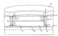
- FIG. 2 illustrates the mattress system of FIG. 1 showing the foot of the mattress with an exemplary connector system.
- FIG. 3 illustrates the mattress system of FIG. 1 with a more detailed view of the connectors.
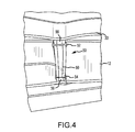
- FIG. 4 is a close-up view of one of the connectors.
- FIG. 5 is still a more detailed view of one of the connectors.
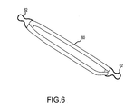
- FIG. 6 illustrates one of the straps that has been removed from the mattress system of FIG. 1 .
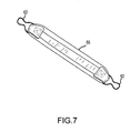
- FIG. 7 illustrates a rear view of the strap of FIG. 6 .
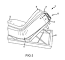
- FIG. 8 illustrates a head end of the mattress system of FIG. 1 when elevated, with the connectors holding the topper to the mattress.
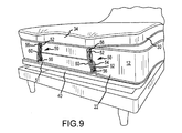
- FIG. 9 is a view of the foot end of the mattress system of FIG. 1 , with the connectors shown holding the topper to the mattress when the foot is elevated.
- the materials that provide comfort to the user, and the materials that provide support to the user are combined in a single mattress unit.
- the support materials such as springs, high density foams and the like
- the comfort materials of a mattress i.e., the soft plush materials closest to the resting body
- One feature of the invention is to address this problem by separating the support materials (also referred to herein as the mattress core) and the comfort materials (also referred to herein as the mattress topper) into two separate and interchangeable entities. While an individual's needs may change through aging, personal preference, or wear of cushioning material, this arrangement avoids replacing the entire unit. Should, for instance, the mattress topper need to be replaced, a user may simply loosen the straps, roll and discard the topper and easily replace it with a new one, all the while keeping their mattress core intact.
- One feature of the invention is the ability to use such toppers with a separate mattress that may be adjusted using an adjustable bed foundation. Because the foundation can raise and lower at an angle, traditional toppers will tend to simply “flop over”. To address this issue, the invention provides various connector straps that secure the topper and mattress together and mitigate against any slippage or movement of the topper. These connectors may also be used with toppers placed on stationary foundations or platform beds where the topper could shift through normal use.
- the invention provides a variety of connector systems that may be used to couple a topper to a mattress.
- the connector systems are configured so that they are easy to install, yet secure enough that they will hold the topper to the mattress, even when surface of the mattress is elevated and/or when excessive weight is placed onto the topper.
- the connector systems will find particular use with adjustable mattresses that utilize one or more mechanisms to elevate the head or foot of the bed. In so doing, the connector systems securely hold the topper to the mattress so that it will not slide off of the mattress. In the event that the topper needs to be changed, the connector systems may easily be removed to allow for removal of the topper.
- the invention may be used with a wide variety of mattresses.
- Such mattresses typically include a core that is covered with a fabric.
- cores that may be used include spring cores, latex cores, air bladders, individually wrapped coil springs, and the like.
- separate pieces of fabric will be used on the top, bottom, and sides, with seams running between the sides and the top and bottom, respectively.
- a piping may included at the outer periphery of the top and bottom of the mattress where the seam extends.
- the fabric segment (such as fabric segment 56 described hereinafter) is sewn into the edge where the border of the mattress core or topper comes into contact with the top or bottom panel of the mattress core or topper. This edge may be further reinforced with a tape edger and Kevlar thread or any other durable thread.
- toppers are generally defined as any type of padding material that loosely rests on top of the mattress.
- the padding material is encased in a fabric.
- the topper may include a generally rectangular piece of foam material having the general shape of the mattress, yet is significantly thinner in thickness.
- toppers may have thicknesses in the range from about one inch to about twelve inches.
- the fabric used to encase the padding material includes seams that run along the outer periphery, and may also include a piping material similar to conventional mattresses. Examples of filling materials that may be used in cores include foams, such as polyurethane foam, visco elastic foams, air bladders, air spacer materials, gels and the like.
- FIG. 1 Shown in FIG. 1 , is one embodiment of a mattress system 10 that comprises a mattress 12 having a top surface 14 , a bottom surface 16 and sides 18 that extend between the top surface 14 and bottom surface 16 .
- the mattress may be defined in terms of a head end 20 and a foot end 22 .
- Mattress 12 may be constructed of a core that is encased in fabric. This fabric may be in multiple pieces that are sewn together along seam lines. In some cases, piping 23 may be placed along the seam lines.
- top surface 14 Disposed on top surface 14 is a topper 30 that may also be defined in terms of a head end 32 and a foot end 34 .
- Topper 30 may comprise a padding material that is encased in fabric similar to mattress 12 .
- Topper 30 may have various seam lines where the fabric is sewn together to encase the padding material.
- the mattress 12 and topper 30 may be used with an adjustable frame 40 that includes various mechanisms 42 to raise and lower various portions of the mattress 12 .
- an adjustable frame 40 that includes various mechanisms 42 to raise and lower various portions of the mattress 12 .
- the head end 20 is inclined as well as the foot end 22 .
- the mattress may be inclined in a variety of different ways.
- the connector systems 50 may be placed at different locations on mattress system 10 . As shown, there are two connector systems 50 at the foot end 22 and two connector systems 50 at the head end 20 . However, it will be appreciated that other numbers could be provided either at the head end or the foot end. Further, although not shown, one or more connector systems 50 could also be placed at the sides 18 of the mattress to couple the topper 30 to the mattress 12 along the sides.
- Each connector system 50 comprises a topper connector 52 and a mattress connector 54 that are coupled to the topper 30 and mattress 12 , respectively.
- the connectors 52 and 54 comprise ring connectors that are sewn to the topper 30 and mattress 12 using fabric segments 56 .
- Fabric segments 56 may be sewn into the seam lines of mattress 12 so that they will not tear away from mattress 12 even when significant force is applied.
- the opposing fabric segments 56 may similarly be sewn into the seam lines of topper 30 .
- connectors 52 and 54 are sewn directly to the mattress 12 and topper 30 (typically into a seam) so that they will not tear or break during use.
- Placed between connectors 52 and 54 is a strap 60 that is used to couple the topper 30 to the mattress 12 .
- Connector 60 is shown in greater detail in FIGS. 6 and 7 .
- Straps 60 may be constructed of a durable fabric, such as a nylon webbing, quilted materials, other non-stretchable fabrics, leather, vinyl, or the like.
- interlocking connector 62 is hourglass in shape and are sewn to each end of strap 60 . In this way, connectors 62 may pass through connectors 52 and 54 and then interlock with each other to secure the topper to the mattress.
- Other types of interlocking connectors could be used, such as snaps, a hook and loop fastener material, buttons, clips, buckles, ties, hook and eye connectors and the like.
- the topper 30 will remain secured to mattress 12 even when the bed is adjusted as illustrated in FIGS. 8 and 9 . As shown, the head and foot ends 20 and 22 may be elevated. In so doing, gravity and the weight of the user will tend to pull topper 30 from off of mattress 12 . However, connector systems 50 hold the topper 30 securely to mattress 12 so that it does not slip off. Further, by constructing connector systems 50 of durable straps and using metal rings as connectors that are sewn to the topper and the mattress, the connection points will not tear and the connectors will not break.
- ring connectors 52 and 54 that are sewn to mattress 12 and topper 30 by fabric segments
- other types of connectors could be used to which straps may be coupled.
- other types of possible connectors include other shaped rings, such as D-rings, O-rings, the like.
- cam and spring buckle connectors could be used to couple a strap to the mattress and topper.
- Other kinds of connectors include slides, loops, strap adjustors, snap hooks, side release buckles, hooks, carabiners, spring links, and the like. Materials that may be used to construct such connectors include metal, plastic, nylon and the like.
- buttons, ties, snaps, clips, and the like could be used to couple straps between the topper and the mattress, including hook and loop fastener materials, buttons, ties, snaps, clips, and the like.
- pieces of hook and loop fabric material may be sewn to the sides of the topper and the mattress.
- Corresponding pieces of hook and loop fastener material could also be coupled to the straps which could then be directly coupled to the mattress and topper by interlinking the opposing pieces of hook and loop fastener materials. Similar processes could be used with buttons, ties, clips, and the like.
- One advantage to using each of these types of connector systems is that they can quickly and easily be used to couple the straps to the topper and the mattress. This permits the topper to be removed in an easy manner whenever needed. Further, these types of systems are strong and durable so that they will not break when excessive force is applied to the straps, such as the topper attempts to move relative to the mattress.
- fabric segments 56 could be made longer and provided with interlocking connectors at their ends. In this way, the fabric segment attached to the topper could be directly coupled to the fabric segment that is attached to the mattress using any of the connectors described herein. In some cases, the two fabric segments could simply be tied to each other. This embodiment would eliminate the need for strap 60 . Further, strap length adjusters could be provided on one or both of the fabric segments to alter their length, if needed.
- fabric segments 56 could be formed as fabric loops that are coupled to the mattress and the topper. A connector, such as a strap, could then be coupled to each of the fabric loops. As another option, the fabric segments 56 could terminate in fabric loops that would serve as connectors so that a strap could be coupled to each of the fabric loops.
Abstract
Description
- In recent years a variety of sleep systems have been proposed in order to enhance user comfort when sleeping on a mattress. For example, padding layers are often added to a mattress to provide additional cushioning. One popular type of padding is the so-called “pillow top” mattress where padding materials are incorporated into a quilting positioned above the mattress.
- Another popular type of cushioning is a “topper” which is a layer of padding that is loosely placed on top of a regular mattress. One problem experienced with toppers is that they can easily slide off the mattress. One traditional way to attach a topper is by user of a mattress cover or mattress pad that envelopes the topper and then surrounds the sides of the mattress. However, these types of mattress covers typically do not work with toppers that are used with adjustable beds that can be inclined or declined.
- The invention provides exemplary connector systems, mattress systems, and associated methods for conveniently coupling a topper to a mattress. Although useful with nearly all toppers and mattresses, the invention will find particular use with adjustable beds where the mattress can be inclined, declined, or height adjusted in other ways. With the mattress systems of the invention, the topper is able to remain firmly secured to the mattress while the bed is adjusted.
- In one particular embodiment, the invention provides a connector system that comprises at least one mattress connector that is coupled to a mattress. Such a mattress can include a top surface, a bottom surface, and four sides extending between the top surface and the bottom surface. The mattress can also conveniently be defined in terms of a head end and a foot end, although it will be appreciated that the position of a sleeper on a mattress may not depend on whether they are at the head end or the foot end. One of the mattress connectors is coupled at the head end and another is coupled at the foot end. Further, at least one topper connector is coupled to the topper at the head end and at the foot end of the topper. A plurality of straps are used to secure the topper to the mattress, with one of the straps being coupled to the mattress connector at the head end of the mattress and to the topper connector at the head end of the topper. The other strap is coupled to the mattress connector at the foot end of the mattress and the topper connector at the foot end of the topper. However, it will be appreciated that the connectors and straps may be provided at other locations as well, and in some cases, only one set of connectors and its associated strap may be needed.
- In one particular arrangement, each strap has two ends, and an interlocking connector is coupled to each end. The interlocking connectors are interlocked to secure the straps to the mattress connectors and the topper connectors after the straps have been inserted through their respective connectors. Although a variety of connectors may be used, one type of mattress connector is a metal ring. A similar connector could also be used for the topper connectors. In one aspect, the interlocking connectors are hourglass shaped so that they may easily be interconnected by inserting one of the connectors through the other connector and then twisting them in opposite directions.
- In another aspect, the mattress connectors and topper connectors may comprise metal D-rings. These metal rings may be coupled to the mattress and the topper using fabric segments that are sewn to the mattress and the topper. As one example, the straps may comprise nylon straps that are sewn to the mattress and the topper. Examples of other connectors that may be used include snaps, a hook and loop fastener material, buttons, clips, buckles, ties, hook and eye connectors and the like.
- In another embodiment, the invention provides a bed that comprises a mattress having a top surface, a bottom surface, and four sides extending between the top surface and the bottom surface. The mattress also has head end and a foot end. A topper is configured to be positioned over a top surface of the mattress and also has a head end and a foot end. At least one mattress connector is coupled to the mattress at the head end and the foot end of the mattress. At least one topper connector is coupled to the topper at the head end and at the foot end of the topper. Straps are then used to couple the mattress to the topper by coupling the strap to the mattress connector at the head end of the mattress and to the topper connector at the head end of the topper. Another strap is coupled to the mattress connector at the foot end of the mattress and to the topper connector at the foot end of the topper.
- The straps may have interlocking connectors that are coupled to each end so that the straps may be placed through the connectors on the mattress and the topper and then interlocked together. For example, the mattress connectors and topper connectors may comprise metal rings, and the interlocking connectors may comprise hourglass shaped rings.
- In another aspect, two or more straps could be coupled to the mattress and the topper at both head end at the foot end in a manner similar to that previously described. Also, one or more straps could be similarly connected at the sides of the mattress.
- In some cases, the mattress will be coupled to an adjustable frame that includes at least one mechanism to vary the height of at least one portion of the mattress. Hence, the adjustable frame may be used to incline, decline or otherwise orient the mattress to the needs of the user. By using the straps as connectors, the topper is prevented from sliding off from the mattress, even with the weight of the user on top of the topper.
- In a further embodiment, the invention provides an exemplary method for coupling a topper to a mattress by using straps that are placed between connectors that are coupled to both the mattress and the topper in a manner similar to that previously described.
-
FIG. 1 is a perspective view of a mattress system shown in use with an adjustable bed. -
FIG. 2 illustrates the mattress system ofFIG. 1 showing the foot of the mattress with an exemplary connector system. -
FIG. 3 illustrates the mattress system ofFIG. 1 with a more detailed view of the connectors. -
FIG. 4 is a close-up view of one of the connectors. -
FIG. 5 is still a more detailed view of one of the connectors. -
FIG. 6 illustrates one of the straps that has been removed from the mattress system ofFIG. 1 . -
FIG. 7 illustrates a rear view of the strap ofFIG. 6 . -
FIG. 8 illustrates a head end of the mattress system ofFIG. 1 when elevated, with the connectors holding the topper to the mattress. -
FIG. 9 is a view of the foot end of the mattress system ofFIG. 1 , with the connectors shown holding the topper to the mattress when the foot is elevated. - In most current mattresses, the materials that provide comfort to the user, and the materials that provide support to the user, are combined in a single mattress unit. In most cases the support materials (such as springs, high density foams and the like) may last for years, while the comfort materials of a mattress (i.e., the soft plush materials closest to the resting body) wear out at much a faster rate.
- One feature of the invention is to address this problem by separating the support materials (also referred to herein as the mattress core) and the comfort materials (also referred to herein as the mattress topper) into two separate and interchangeable entities. While an individual's needs may change through aging, personal preference, or wear of cushioning material, this arrangement avoids replacing the entire unit. Should, for instance, the mattress topper need to be replaced, a user may simply loosen the straps, roll and discard the topper and easily replace it with a new one, all the while keeping their mattress core intact.
- One feature of the invention is the ability to use such toppers with a separate mattress that may be adjusted using an adjustable bed foundation. Because the foundation can raise and lower at an angle, traditional toppers will tend to simply “flop over”. To address this issue, the invention provides various connector straps that secure the topper and mattress together and mitigate against any slippage or movement of the topper. These connectors may also be used with toppers placed on stationary foundations or platform beds where the topper could shift through normal use.
- Hence, the invention provides a variety of connector systems that may be used to couple a topper to a mattress. The connector systems are configured so that they are easy to install, yet secure enough that they will hold the topper to the mattress, even when surface of the mattress is elevated and/or when excessive weight is placed onto the topper. For example, the connector systems will find particular use with adjustable mattresses that utilize one or more mechanisms to elevate the head or foot of the bed. In so doing, the connector systems securely hold the topper to the mattress so that it will not slide off of the mattress. In the event that the topper needs to be changed, the connector systems may easily be removed to allow for removal of the topper.
- The invention may be used with a wide variety of mattresses. Such mattresses typically include a core that is covered with a fabric. Examples of cores that may be used include spring cores, latex cores, air bladders, individually wrapped coil springs, and the like. Typically, separate pieces of fabric will be used on the top, bottom, and sides, with seams running between the sides and the top and bottom, respectively. In some cases, a piping may included at the outer periphery of the top and bottom of the mattress where the seam extends. In one particularly advantageous embodiment, the fabric segment (such as
fabric segment 56 described hereinafter) is sewn into the edge where the border of the mattress core or topper comes into contact with the top or bottom panel of the mattress core or topper. This edge may be further reinforced with a tape edger and Kevlar thread or any other durable thread. - The invention may also utilize a wide variety of toppers that are positioned on top of the mattress. Toppers are generally defined as any type of padding material that loosely rests on top of the mattress. In some cases, the padding material is encased in a fabric. As one example, the topper may include a generally rectangular piece of foam material having the general shape of the mattress, yet is significantly thinner in thickness. Merely by way of example, toppers may have thicknesses in the range from about one inch to about twelve inches. Typically, the fabric used to encase the padding material includes seams that run along the outer periphery, and may also include a piping material similar to conventional mattresses. Examples of filling materials that may be used in cores include foams, such as polyurethane foam, visco elastic foams, air bladders, air spacer materials, gels and the like.
- Shown in
FIG. 1 , is one embodiment of amattress system 10 that comprises amattress 12 having atop surface 14, abottom surface 16 andsides 18 that extend between thetop surface 14 andbottom surface 16. For convenience of discussion, the mattress may be defined in terms of ahead end 20 and afoot end 22.Mattress 12 may be constructed of a core that is encased in fabric. This fabric may be in multiple pieces that are sewn together along seam lines. In some cases, piping 23 may be placed along the seam lines. - Disposed on
top surface 14 is atopper 30 that may also be defined in terms of ahead end 32 and afoot end 34.Topper 30 may comprise a padding material that is encased in fabric similar tomattress 12.Topper 30 may have various seam lines where the fabric is sewn together to encase the padding material. - Optionally, the
mattress 12 andtopper 30 may be used with anadjustable frame 40 that includesvarious mechanisms 42 to raise and lower various portions of themattress 12. For example, as shown inFIG. 1 thehead end 20 is inclined as well as thefoot end 22. However, it will be appreciated that the mattress may be inclined in a variety of different ways. - Referring also now to
FIGS. 2-5 ,exemplary connector systems 50 that are used to couple thetopper 30 tomattress 12 will be described. Theconnector systems 50 may be placed at different locations onmattress system 10. As shown, there are twoconnector systems 50 at thefoot end 22 and twoconnector systems 50 at thehead end 20. However, it will be appreciated that other numbers could be provided either at the head end or the foot end. Further, although not shown, one ormore connector systems 50 could also be placed at thesides 18 of the mattress to couple thetopper 30 to themattress 12 along the sides. - Each
connector system 50 comprises atopper connector 52 and amattress connector 54 that are coupled to thetopper 30 andmattress 12, respectively. Theconnectors topper 30 andmattress 12 usingfabric segments 56.Fabric segments 56 may be sewn into the seam lines ofmattress 12 so that they will not tear away frommattress 12 even when significant force is applied. The opposingfabric segments 56 may similarly be sewn into the seam lines oftopper 30. In this way,connectors mattress 12 and topper 30 (typically into a seam) so that they will not tear or break during use. Placed betweenconnectors strap 60 that is used to couple thetopper 30 to themattress 12.Connector 60 is shown in greater detail inFIGS. 6 and 7 .Straps 60 may be constructed of a durable fabric, such as a nylon webbing, quilted materials, other non-stretchable fabrics, leather, vinyl, or the like. Further, at each end ofstrap 60 is an interlockingconnector 62. As shown, interlockingconnectors 62 are hourglass in shape and are sewn to each end ofstrap 60. In this way,connectors 62 may pass throughconnectors - Once securely connected, the
topper 30 will remain secured tomattress 12 even when the bed is adjusted as illustrated inFIGS. 8 and 9 . As shown, the head and foot ends 20 and 22 may be elevated. In so doing, gravity and the weight of the user will tend to pulltopper 30 from off ofmattress 12. However,connector systems 50 hold thetopper 30 securely tomattress 12 so that it does not slip off. Further, by constructingconnector systems 50 of durable straps and using metal rings as connectors that are sewn to the topper and the mattress, the connection points will not tear and the connectors will not break. - Although shown with
ring connectors mattress 12 andtopper 30 by fabric segments, it will be appreciated that other types of connectors could be used to which straps may be coupled. For example, instead of using a ring connector, other types of possible connectors include other shaped rings, such as D-rings, O-rings, the like. Also, cam and spring buckle connectors could be used to couple a strap to the mattress and topper. Other kinds of connectors include slides, loops, strap adjustors, snap hooks, side release buckles, hooks, carabiners, spring links, and the like. Materials that may be used to construct such connectors include metal, plastic, nylon and the like. In some cases, other types of fasteners could be used to couple straps between the topper and the mattress, including hook and loop fastener materials, buttons, ties, snaps, clips, and the like. As one specific example, pieces of hook and loop fabric material may be sewn to the sides of the topper and the mattress. Corresponding pieces of hook and loop fastener material could also be coupled to the straps which could then be directly coupled to the mattress and topper by interlinking the opposing pieces of hook and loop fastener materials. Similar processes could be used with buttons, ties, clips, and the like. One advantage to using each of these types of connector systems is that they can quickly and easily be used to couple the straps to the topper and the mattress. This permits the topper to be removed in an easy manner whenever needed. Further, these types of systems are strong and durable so that they will not break when excessive force is applied to the straps, such as the topper attempts to move relative to the mattress. - In another embodiment,
fabric segments 56 could be made longer and provided with interlocking connectors at their ends. In this way, the fabric segment attached to the topper could be directly coupled to the fabric segment that is attached to the mattress using any of the connectors described herein. In some cases, the two fabric segments could simply be tied to each other. This embodiment would eliminate the need forstrap 60. Further, strap length adjusters could be provided on one or both of the fabric segments to alter their length, if needed. - In a further option,
fabric segments 56 could be formed as fabric loops that are coupled to the mattress and the topper. A connector, such as a strap, could then be coupled to each of the fabric loops. As another option, thefabric segments 56 could terminate in fabric loops that would serve as connectors so that a strap could be coupled to each of the fabric loops. - The invention has now been described in detail for purposes of clarity and understanding. However, it will be appreciated that certain changes and modifications may be practiced within the scope of the appended claims.
Claims (16)
Priority Applications (1)
| Application Number | Priority Date | Filing Date | Title |
|---|---|---|---|
| US13/360,207 US8856985B2 (en) | 2012-01-27 | 2012-01-27 | Connector system for mattress |
Applications Claiming Priority (1)
| Application Number | Priority Date | Filing Date | Title |
|---|---|---|---|
| US13/360,207 US8856985B2 (en) | 2012-01-27 | 2012-01-27 | Connector system for mattress |
Publications (2)
| Publication Number | Publication Date |
|---|---|
| US20130192001A1 true US20130192001A1 (en) | 2013-08-01 |
| US8856985B2 US8856985B2 (en) | 2014-10-14 |
Family
ID=48868951
Family Applications (1)
| Application Number | Title | Priority Date | Filing Date |
|---|---|---|---|
| US13/360,207 Active 2032-10-12 US8856985B2 (en) | 2012-01-27 | 2012-01-27 | Connector system for mattress |
Country Status (1)
| Country | Link |
|---|---|
| US (1) | US8856985B2 (en) |
Cited By (8)
| Publication number | Priority date | Publication date | Assignee | Title |
|---|---|---|---|---|
| US20140245536A1 (en) * | 2013-01-24 | 2014-09-04 | Ergomotion, Inc. | Adjustable bed mattress retainer system |
| US20150040325A1 (en) * | 2013-07-29 | 2015-02-12 | Melinda Bennett | Mattress Pad and Bed Pan Assembly |
| JP2018057492A (en) * | 2016-10-03 | 2018-04-12 | 西川産業株式会社 | mattress |
| US10285518B1 (en) * | 2016-02-29 | 2019-05-14 | Jack Nekhala | Sheet bed tightener |
| US10517412B1 (en) * | 2016-02-29 | 2019-12-31 | Jack Nekhala | Sheet bed tightener |
| US11284726B1 (en) * | 2019-03-08 | 2022-03-29 | Trinity Guardion, Inc. | Barrier for mattress and bed deck |
| US20220287468A1 (en) * | 2021-03-09 | 2022-09-15 | Kyle Parker Blatt | Bedding securement system |
| US11786050B2 (en) * | 2019-02-20 | 2023-10-17 | Benoit DERAGON | Mattress with variable height and hardness and method for adjusting the height and hardness of the same |
Families Citing this family (7)
| Publication number | Priority date | Publication date | Assignee | Title |
|---|---|---|---|---|
| US8464720B1 (en) | 2012-01-10 | 2013-06-18 | Alessio Pigazzi | Method of securing a patient onto an operating table when the patient is in the trendelenburg position and apparatus therefor including a kit |
| US10322050B1 (en) | 2012-01-10 | 2019-06-18 | Alessio Pigazzi | Method of securing a patient onto an operating table when the patient is in a position such as the Trendelenburg position and apparatus therefor including a kit |
| US10912699B2 (en) | 2012-01-10 | 2021-02-09 | Alessio Pigazzi | Method of securing a patient onto an operating table when the patient is in a position such as the trendelenburg position and apparatus therefor including a kit |
| US10478364B2 (en) | 2014-03-10 | 2019-11-19 | Stryker Corporation | Limb positioning system |
| US9951904B2 (en) | 2015-03-24 | 2018-04-24 | Stryker Corporation | Rotatable seat clamps for rail clamp |
| US11684530B2 (en) | 2019-04-12 | 2023-06-27 | Hill-Rom Services, Inc. | Mattress retention assembly and radiofrequency weld in surface covers |
| US10624464B2 (en) | 2019-07-11 | 2020-04-21 | Mohammed Shuaib | Double mattress connecting system |
Citations (10)
| Publication number | Priority date | Publication date | Assignee | Title |
|---|---|---|---|---|
| US805330A (en) * | 1905-05-18 | 1905-11-21 | Daniel I Tompkins | Fastening device for mattresses. |
| US1842873A (en) * | 1930-07-29 | 1932-01-26 | Mary E Leeking | Mattress holder |
| US2661486A (en) * | 1950-03-28 | 1953-12-08 | Earl E Roher | Combination box spring and mattress |
| US4336621A (en) * | 1980-02-25 | 1982-06-29 | Schwartz Donald R | Disposable orthopedic overmattress for articulated beds |
| US4653131A (en) * | 1984-10-15 | 1987-03-31 | Diehl Dolores M | Bed sheet restraint |
| US6233764B1 (en) * | 1999-02-22 | 2001-05-22 | Zephtex Industries Incorporated | Bed assemblies |
| US6687935B2 (en) * | 1995-11-30 | 2004-02-10 | Hill-Rom Services, Inc. | Mattress structure |
| US20040060113A1 (en) * | 2002-10-01 | 2004-04-01 | Lantagne Lynda D. | Restraint for bed covers |
| US7832033B1 (en) * | 2009-02-24 | 2010-11-16 | Glen Berkshire | Cover for preventing a person lying on a bed from falling off the bed |
| US20110005000A1 (en) * | 2009-07-13 | 2011-01-13 | Downey + Rippe, LLC | Mattress and bed deck cover |
Family Cites Families (14)
| Publication number | Priority date | Publication date | Assignee | Title |
|---|---|---|---|---|
| US1972919A (en) | 1932-07-22 | 1934-09-11 | Ersyl F Chambless | Device for holding sheets and bedclothes in place |
| US1959920A (en) | 1933-06-17 | 1934-05-22 | Charles Karr Company | Pad holder |
| US2254423A (en) | 1939-08-26 | 1941-09-02 | Gerry Lenore | Bed cozy |
| US2188576A (en) | 1939-09-11 | 1940-01-30 | Mulloy Mary Elizabeth | Harness for bedclothes |
| US2838770A (en) | 1955-07-18 | 1958-06-17 | Jimmie A Chezem | Bed cover retainer assembly |
| US2896226A (en) | 1956-10-30 | 1959-07-28 | Swicegood Lucy-Jim Davis | Bedding |
| US3394416A (en) | 1965-12-10 | 1968-07-30 | Edith A. Hale | Bed covering |
| US3530516A (en) | 1967-11-06 | 1970-09-29 | Edmond R T Marquette | Blanket with interchangeable halves |
| JPS6017162Y2 (en) | 1982-12-24 | 1985-05-27 | 幹三 小林 | Mat attachment device for fastening sheets |
| US5072470A (en) | 1989-11-11 | 1991-12-17 | Lysiak Phillip J | Device for holding bedclothes in a fixed position on a bed |
| US6009579A (en) | 1997-08-28 | 2000-01-04 | Pacific Coast Feather Company | Filled topper and featherbed combination |
| US6715173B2 (en) | 2001-02-22 | 2004-04-06 | Sealy Technology Llc | Modular sleep systems with friction-secured comfort unit |
| US20090172881A1 (en) | 2008-03-03 | 2009-07-09 | Marlene Marian Peterson | Mattress Wrap Bedding System |
| US20100154125A1 (en) | 2008-12-19 | 2010-06-24 | Fernando Fratovich | Apparatus and Method for Compressing a Mattress to a Uniform Firmness |
-
2012
- 2012-01-27 US US13/360,207 patent/US8856985B2/en active Active
Patent Citations (10)
| Publication number | Priority date | Publication date | Assignee | Title |
|---|---|---|---|---|
| US805330A (en) * | 1905-05-18 | 1905-11-21 | Daniel I Tompkins | Fastening device for mattresses. |
| US1842873A (en) * | 1930-07-29 | 1932-01-26 | Mary E Leeking | Mattress holder |
| US2661486A (en) * | 1950-03-28 | 1953-12-08 | Earl E Roher | Combination box spring and mattress |
| US4336621A (en) * | 1980-02-25 | 1982-06-29 | Schwartz Donald R | Disposable orthopedic overmattress for articulated beds |
| US4653131A (en) * | 1984-10-15 | 1987-03-31 | Diehl Dolores M | Bed sheet restraint |
| US6687935B2 (en) * | 1995-11-30 | 2004-02-10 | Hill-Rom Services, Inc. | Mattress structure |
| US6233764B1 (en) * | 1999-02-22 | 2001-05-22 | Zephtex Industries Incorporated | Bed assemblies |
| US20040060113A1 (en) * | 2002-10-01 | 2004-04-01 | Lantagne Lynda D. | Restraint for bed covers |
| US7832033B1 (en) * | 2009-02-24 | 2010-11-16 | Glen Berkshire | Cover for preventing a person lying on a bed from falling off the bed |
| US20110005000A1 (en) * | 2009-07-13 | 2011-01-13 | Downey + Rippe, LLC | Mattress and bed deck cover |
Cited By (12)
| Publication number | Priority date | Publication date | Assignee | Title |
|---|---|---|---|---|
| US20140245536A1 (en) * | 2013-01-24 | 2014-09-04 | Ergomotion, Inc. | Adjustable bed mattress retainer system |
| US9107782B2 (en) * | 2013-01-24 | 2015-08-18 | Ergomotion, Inc. | Adjustable bed mattress retainer system |
| US20150040325A1 (en) * | 2013-07-29 | 2015-02-12 | Melinda Bennett | Mattress Pad and Bed Pan Assembly |
| US10285518B1 (en) * | 2016-02-29 | 2019-05-14 | Jack Nekhala | Sheet bed tightener |
| US10517412B1 (en) * | 2016-02-29 | 2019-12-31 | Jack Nekhala | Sheet bed tightener |
| JP2018057492A (en) * | 2016-10-03 | 2018-04-12 | 西川産業株式会社 | mattress |
| JP7032774B2 (en) | 2016-10-03 | 2022-03-09 | 西川株式会社 | mattress |
| US11786050B2 (en) * | 2019-02-20 | 2023-10-17 | Benoit DERAGON | Mattress with variable height and hardness and method for adjusting the height and hardness of the same |
| US11284726B1 (en) * | 2019-03-08 | 2022-03-29 | Trinity Guardion, Inc. | Barrier for mattress and bed deck |
| US20220211189A1 (en) * | 2019-03-08 | 2022-07-07 | Trinity Guardion, Llc | Barrier for mattress and bed deck |
| US20220287468A1 (en) * | 2021-03-09 | 2022-09-15 | Kyle Parker Blatt | Bedding securement system |
| US11559142B2 (en) * | 2021-03-09 | 2023-01-24 | Kyle Parker Blatt | Bedding securement system |
Also Published As
| Publication number | Publication date |
|---|---|
| US8856985B2 (en) | 2014-10-14 |
Similar Documents
| Publication | Publication Date | Title |
|---|---|---|
| US8856985B2 (en) | Connector system for mattress | |
| US11019937B2 (en) | Furniture construction with elastic or spring modules | |
| US11602227B2 (en) | Mattresses including spacer fabric and related methods | |
| US8321977B1 (en) | Feeding pillow with removable support surface | |
| JP2702087B2 (en) | Mattress and pillow top assembly | |
| AU2004281775B2 (en) | Pillow top for a cushion | |
| US7886385B2 (en) | Mattress with quilted zoned topper | |
| US8393027B2 (en) | Spinal support pivot pillow | |
| US20210161302A1 (en) | Mattresses with multiple customizable and replaceable levels and sections and methods thereof | |
| US9060620B1 (en) | Baby restraining article | |
| US11786050B2 (en) | Mattress with variable height and hardness and method for adjusting the height and hardness of the same | |
| US11206937B2 (en) | Bed sheets with performance fabric | |
| US20150320228A1 (en) | Foam block mattress assembly | |
| US11497320B2 (en) | Dual firmness spring mattress | |
| JP5721088B1 (en) | pillow | |
| JP2016077869A (en) | pillow | |
| JP7441548B2 (en) | bedding set | |
| CN212139986U (en) | Multi-position comfortable-sleeping combined mattress | |
| JP2023022631A (en) | sleeping posture holder | |
| WO2023177385A1 (en) | Anti-hammocking performance fabric and device for multi-layered modular mattress systems and multi-layered modular mattresses using same. | |
| US20160128489A1 (en) | Rotatable Mattress | |
| JP2015218402A (en) | skirt |
Legal Events
| Date | Code | Title | Description |
|---|---|---|---|
| AS | Assignment |
Owner name: DENVER MATTRESS CO. LLC, COLORADO Free format text: ASSIGNMENT OF ASSIGNORS INTEREST;ASSIGNORS:RENSINK, BOB;AMENDOLA, JONATHAN;REEL/FRAME:028038/0885 Effective date: 20120412 |
|
| STCF | Information on status: patent grant |
Free format text: PATENTED CASE |
|
| MAFP | Maintenance fee payment |
Free format text: PAYMENT OF MAINTENANCE FEE, 4TH YEAR, LARGE ENTITY (ORIGINAL EVENT CODE: M1551) Year of fee payment: 4 |
|
| MAFP | Maintenance fee payment |
Free format text: PAYMENT OF MAINTENANCE FEE, 8TH YEAR, LARGE ENTITY (ORIGINAL EVENT CODE: M1552); ENTITY STATUS OF PATENT OWNER: LARGE ENTITY Year of fee payment: 8 |