US20140196587A1 - Double-barrel trimmer for plant materials - Google Patents
Double-barrel trimmer for plant materials Download PDFInfo
- Publication number
- US20140196587A1 US20140196587A1 US14/155,686 US201414155686A US2014196587A1 US 20140196587 A1 US20140196587 A1 US 20140196587A1 US 201414155686 A US201414155686 A US 201414155686A US 2014196587 A1 US2014196587 A1 US 2014196587A1
- Authority
- US
- United States
- Prior art keywords
- trimmer
- barrel
- plant
- belt
- plant trimmer
- Prior art date
- Legal status (The legal status is an assumption and is not a legal conclusion. Google has not performed a legal analysis and makes no representation as to the accuracy of the status listed.)
- Granted
Links
Images


Classifications
-
- B—PERFORMING OPERATIONS; TRANSPORTING
- B26—HAND CUTTING TOOLS; CUTTING; SEVERING
- B26D—CUTTING; DETAILS COMMON TO MACHINES FOR PERFORATING, PUNCHING, CUTTING-OUT, STAMPING-OUT OR SEVERING
- B26D1/00—Cutting through work characterised by the nature or movement of the cutting member or particular materials not otherwise provided for; Apparatus or machines therefor; Cutting members therefor
- B26D1/01—Cutting through work characterised by the nature or movement of the cutting member or particular materials not otherwise provided for; Apparatus or machines therefor; Cutting members therefor involving a cutting member which does not travel with the work
- B26D1/12—Cutting through work characterised by the nature or movement of the cutting member or particular materials not otherwise provided for; Apparatus or machines therefor; Cutting members therefor involving a cutting member which does not travel with the work having a cutting member moving about an axis
- B26D1/25—Cutting through work characterised by the nature or movement of the cutting member or particular materials not otherwise provided for; Apparatus or machines therefor; Cutting members therefor involving a cutting member which does not travel with the work having a cutting member moving about an axis with a non-circular cutting member
- B26D1/34—Cutting through work characterised by the nature or movement of the cutting member or particular materials not otherwise provided for; Apparatus or machines therefor; Cutting members therefor involving a cutting member which does not travel with the work having a cutting member moving about an axis with a non-circular cutting member moving about an axis parallel to the line of cut
- B26D1/36—Cutting through work characterised by the nature or movement of the cutting member or particular materials not otherwise provided for; Apparatus or machines therefor; Cutting members therefor involving a cutting member which does not travel with the work having a cutting member moving about an axis with a non-circular cutting member moving about an axis parallel to the line of cut and rotating continuously in one direction during cutting, e.g. mounted on a rotary cylinder
-
- A—HUMAN NECESSITIES
- A01—AGRICULTURE; FORESTRY; ANIMAL HUSBANDRY; HUNTING; TRAPPING; FISHING
- A01G—HORTICULTURE; CULTIVATION OF VEGETABLES, FLOWERS, RICE, FRUIT, VINES, HOPS OR SEAWEED; FORESTRY; WATERING
- A01G3/00—Cutting implements specially adapted for horticultural purposes; Delimbing standing trees
- A01G3/04—Apparatus for trimming hedges, e.g. hedge shears
- A01G3/0435—Machines specially adapted for shaping plants, e.g. topiaries
-
- A—HUMAN NECESSITIES
- A01—AGRICULTURE; FORESTRY; ANIMAL HUSBANDRY; HUNTING; TRAPPING; FISHING
- A01G—HORTICULTURE; CULTIVATION OF VEGETABLES, FLOWERS, RICE, FRUIT, VINES, HOPS OR SEAWEED; FORESTRY; WATERING
- A01G3/00—Cutting implements specially adapted for horticultural purposes; Delimbing standing trees
- A01G3/08—Other tools for pruning, branching or delimbing standing trees
-
- B—PERFORMING OPERATIONS; TRANSPORTING
- B26—HAND CUTTING TOOLS; CUTTING; SEVERING
- B26D—CUTTING; DETAILS COMMON TO MACHINES FOR PERFORATING, PUNCHING, CUTTING-OUT, STAMPING-OUT OR SEVERING
- B26D1/00—Cutting through work characterised by the nature or movement of the cutting member or particular materials not otherwise provided for; Apparatus or machines therefor; Cutting members therefor
- B26D1/01—Cutting through work characterised by the nature or movement of the cutting member or particular materials not otherwise provided for; Apparatus or machines therefor; Cutting members therefor involving a cutting member which does not travel with the work
- B26D1/12—Cutting through work characterised by the nature or movement of the cutting member or particular materials not otherwise provided for; Apparatus or machines therefor; Cutting members therefor involving a cutting member which does not travel with the work having a cutting member moving about an axis
- B26D1/25—Cutting through work characterised by the nature or movement of the cutting member or particular materials not otherwise provided for; Apparatus or machines therefor; Cutting members therefor involving a cutting member which does not travel with the work having a cutting member moving about an axis with a non-circular cutting member
- B26D1/34—Cutting through work characterised by the nature or movement of the cutting member or particular materials not otherwise provided for; Apparatus or machines therefor; Cutting members therefor involving a cutting member which does not travel with the work having a cutting member moving about an axis with a non-circular cutting member moving about an axis parallel to the line of cut
- B26D1/40—Cutting through work characterised by the nature or movement of the cutting member or particular materials not otherwise provided for; Apparatus or machines therefor; Cutting members therefor involving a cutting member which does not travel with the work having a cutting member moving about an axis with a non-circular cutting member moving about an axis parallel to the line of cut and coacting with a rotary member
-
- Y—GENERAL TAGGING OF NEW TECHNOLOGICAL DEVELOPMENTS; GENERAL TAGGING OF CROSS-SECTIONAL TECHNOLOGIES SPANNING OVER SEVERAL SECTIONS OF THE IPC; TECHNICAL SUBJECTS COVERED BY FORMER USPC CROSS-REFERENCE ART COLLECTIONS [XRACs] AND DIGESTS
- Y10—TECHNICAL SUBJECTS COVERED BY FORMER USPC
- Y10T—TECHNICAL SUBJECTS COVERED BY FORMER US CLASSIFICATION
- Y10T83/00—Cutting
- Y10T83/465—Cutting motion of tool has component in direction of moving work
- Y10T83/474—With work feed speed regulator
-
- Y—GENERAL TAGGING OF NEW TECHNOLOGICAL DEVELOPMENTS; GENERAL TAGGING OF CROSS-SECTIONAL TECHNOLOGIES SPANNING OVER SEVERAL SECTIONS OF THE IPC; TECHNICAL SUBJECTS COVERED BY FORMER USPC CROSS-REFERENCE ART COLLECTIONS [XRACs] AND DIGESTS
- Y10—TECHNICAL SUBJECTS COVERED BY FORMER USPC
- Y10T—TECHNICAL SUBJECTS COVERED BY FORMER US CLASSIFICATION
- Y10T83/00—Cutting
- Y10T83/465—Cutting motion of tool has component in direction of moving work
- Y10T83/4766—Orbital motion of cutting blade
- Y10T83/4795—Rotary tool
Definitions
- This disclosure relates to trimmers for plant materials.
- Single-barrel mechanized trimmers exist and are widely used to trim stems and leaves from harvested plant material, such as, for example, hops, rosemary, oregano, basil, mint, lavender, coriander, parsley, mixed flowers, and other plant materials which may be used in the preparation of essential oils.
- trimmers are sometimes operated in sequence, with the output stream from a first trimmer being fed into the inlet of the barrel of a second trimmer. This allows the plant material to be fed through the serially connected trimmer barrels at a faster rate while achieving a similar trimmed condition in the final output stream.
- the speed of the plant material through the trimmer may be varied by tilting the front end of the trimmer—the end of the trimmer with a hopper or funnel into which plant material is fed—higher than the back end of the trimmer—the end out of which the output stream flows. Tilting the trimmer is presently only achieved by using blocks or ramps to prop the front end up higher than the back end or by rotating the entire trimmer on a mechanism within the trimmer's frame (which may be difficult to do when the trimmers are positioned in sequence). This is awkward, time consuming, and may result in compromises between improving the trimmed condition of the plant material versus putting more time into adjusting the blocks or ramps used to tilt the trimmer.
- FIG. 1 is a right elevation view of an embodiment.
- FIG. 2 is a left elevation view of an embodiment.
- FIG. 3 is a back elevation view of an embodiment.
- FIG. 4 is an isometric back-left-top view of an embodiment.
- FIG. 5A is a back elevation view of an embodiment with components hidden.
- FIG. 5B is an isometric back-right-top view of an embodiment with the same components hidden as in FIG. 5A .
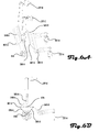
- FIG. 6A is a back-left-top isometric view of an embodiment of the blades and the reel axle.
- FIG. 6B is a back elevation view of an embodiment of the blades and the reel axle.
- FIG. 7 is a front-right-top isometric view of an embodiment.
- FIG. 8 is a front elevation view of an embodiment.
- FIG. 9 is a front elevation view of an embodiment with components hidden.
- FIG. 10 is a front elevation view of an embodiment with more components hidden relative to FIG. 9 .
- FIG. 11 is a front-right-bottom isometric view of an embodiment with more components hidden relative to FIG. 10 .
- FIG. 12A is a left elevation view of an embodiment with the same components hidden as in FIG. 11 .
- FIG. 12B is a right elevation view of an embodiment with the same components hidden as in FIG. 11 .
- FIG. 13 is a top plan view, with the front of the trimmer at the bottom of the illustration.
- FIG. 14A is a back-left-top isometric view of a barrel power train.
- FIG. 14B is a front-right-top isometric view of a reel power train.
- FIG. 15A is a back-right-top isometric view of an embodiment of a trimmer-trimmer support.
- FIG. 15B is a back-right-bottom isometric view of the trimmer-trimmer support illustrated in FIG. 15A .
- FIG. 16A is a front-right-top isometric view of an embodiment of a trimmer-trimmer support.
- FIG. 16B is a detailed front-right-top isometric view of the trimmer-trimmer support illustrated in FIG. 16A .
- FIG. 17A is a right side elevation view of an embodiment of a trimmer-trimmer support.
- FIG. 17B is a back-right-top isometric view of the trimmer-trimmer support illustrated in FIG. 17A .
- FIG. 17C is a back-right-top perspective view of a portion of the trimmer-trimmer support illustrated in FIG. 17A .
- FIG. 18 is a schematic diagram of electronics in a trimmer embodiment.
- “releasable,” “connect,” “connected,” “connectable,” “disconnect,” “disconnected,” and “disconnectable” refers to two or more structures which may be connected or disconnected, generally without the use of tools (examples of tools including screwdrivers, pliers, drills, saws, welding machines, torches, irons, and other heat sources) and generally in a repeatable manner.
- “attach,” “attached,” or “attachable” refers to two or more structures or components which are attached through the use of tools or chemical or physical bonding.
- “secure,” “secured,” or “securable” refers to two or more structures or components which are either connected or attached.
- the disclosed Trimmer 100 comprises a Cart Frame 107 secured to other components.
- a Hopper 101 receives plant material (not shown) and channels the plant material toward two Barrel Inlets 515 -A and 515 -B ( FIG. 5A illustrates the Barrel Inlets 515 in elevation; please see FIG. 5B and FIG. 7 for an isometric view of Barrel Inlets 515 ).
- the end of the Trimmer 100 with the Hopper 101 is referred to herein as the “front” of the Trimmer 100 .
- References herein to “right” and “left” sides of the Trimmer 100 are relative to a viewer looking at the front of the trimmer, down its long axis.
- Barrel Inlets 515 and Barrel Outlets 117 -A and 117 -B are separately secured to or abut a Left Barrel 111 -B and a Right Barrel 111 -A (referred to collectively as “Barrels 111 ”).
- the Left Barrel 111 -B and Right Barrel 111 -A are perforated.
- the perforations form a rifled helical pattern, with the perforation rifling mirrored, one Barrel 111 relative to the other.
- the Barrel 111 rifling encourages movement of the plant material down the Barrels 111 when the Barrels 111 rotate. Barrel perforations in previous plant trimmers are not known to be rifled.
- the Barrel 111 perforation rifling is mirrored because the Barrels 111 counter-rotate, which requires that the rifling be mirrored in order to encourage movement of the plant material down the Barrels 111 when the Barrels 111 rotate.
- the Barrels 111 are driven by a Barrel Motor 121 , attached to the Barrels 111 by a Barrel Power Train 1479 (discussed further herein).
- a Barrel Motor 121 attached to the Barrels 111 by a Barrel Power Train 1479 (discussed further herein).
- the Right Barrel 111 -A rotates clockwise while the Left Barrel 111 -B rotates counter-clockwise. Because the Barrels 111 counter-rotate, plant material fed into the Barrels 111 accumulates on the side of each Barrel 111 toward the center of the Trimmer 100 .
- the Trimmer 100 further comprises a single rotating cutting Reel 547 , a Right Barrel Blade 549 -A, and a Left Barrel Blade 549 -B (“Barrel Blades 549 ”).
- the Reel 547 comprises a set of helical reel blades radially arranged around a Reel Axle 646 .
- the Barrel Blades 549 are positioned generally on the underside of and between the Barrels 111 , oriented along the same long horizontal axis.
- the Right Blade Edge 657 -A and the Left Blade Edge 657 -B (“Blade Edges 657 ”) contact, graze, or become proximate to the Reel 547 forming what are hereinafter referred to as “Cut Locations.”
- the Blade Edges 657 and Cut Locations are approximately equidistant from the center of the Reel Axle 646 .
- the Barrel Blades 549 may be omitted, operating the Trimmer 100 solely with the Reel 547 and the Barrels 111 .
- the Barrel Blades 549 may also or alternatively serve to clean resin and other residue off of the Reel 547 .
- the plant material tumbles as it transits the Barrels 111 , creating opportunity for the projecting plant material to be adequately trimmed if it spends enough time in the Barrels.
- the Trimmer 100 outputs two streams: A “Primary Stream” issues from the back of the Trimmer 100 , through the Barrel Outlets 117 .
- the Primary Stream comprises relatively compact clusters of material, such as flower buds or cones.
- a “Secondary Stream” issues from Waste Outlets 119 -A and 119 -B, comprising trimmed waste material, such as stems and leaves. While referred to herein as “waste,” the Secondary Stream may, in fact, be utilized while the Primary Stream may not be utilized; the characteristics and uses of the two streams may depend upon the plant material being processed and the outcome desired by the processor.
- a vacuum (not shown) may be attached to the Waste Outlets 119 to facilitate removal of the Secondary Stream from the Trimmer 100 . The correct vacuum force will keep the plant material in locations within the Barrels 111 and/or for a span of time within the Barrels 111 , which locations and/or span of time facilitate trimming and improve trimming efficiency.
- the Barrel Power Train 1479 transfers power from the Barrel Motor 121 to the Barrels 111 and causes the Barrels 111 to counter-rotate.
- the drawings illustrate an embodiment in which the Barrel Power Train 1479 comprises a Barrel Motor 121 , a Barrel Motor Gear Box 1267 , a Barrel Belt 141 , Roller 322 , a Right Drive Train Ring 316 -A and a Left Drive Train Ring 316 -B (“Drive Train Rings 316 ”) separately secured to each Barrel 111 , which Drive Train Rings 316 engage with the Barrel Belt 141 .
- Rollers, such as Roller 322 guide the Barrel Belt 141 to contact the Right Barrel 111 -A.
- the interior perimeter of the Barrel Belt 141 engages with the Left Drive Train Ring 316 -B while the exterior perimeter of the Barrel Belt 141 engages with the Right Drive Train Ring 316 -A.
- the result is that the Left Barrel 111 -B rotates in the same direction as the Barrel Motor 121 , while the Right Barrel 111 -A rotates in the opposite direction.
- the Right Barrel 111 -A rotates clockwise, indicated by element 912
- the Left Barrel 111 -B rotates counter-clockwise, indicated by element 914 .
- Plant material traversing the Barrels 111 then has a tendency to accumulate in the lower right-hand quadrant of the Left Barrel 111 -B and to accumulate in the lower left-hand quadrant of the Right Barrel 111 -A, generally above the center of the Reel 547 .
- the Barrel Power Train 1479 may be provided by a number of embodiments, such as a by one or more motors connected to the Barrels by a shaft and gears, by a belt, a chain, by hydraulic lines and couplings, or by other power transmission means.
- the Barrel Power Train 1479 may provide power directly to a first Barrel, while the second Barrel obtains power from the first Barrel, such as via a gear, chain, belt, and the like.
- FIGS. 5A , 5 B, 6 A and 6 B illustrate an embodiment from the rear, with components hidden to illustrate the position of the Barrel Blades 549 relative to the Reel 547 ( FIGS. 6A and 6B illustrate the Reel Axle 646 , but not the Reel 547 ).
- the Blade Edges 657 may be on a common Horizontal Plane 675 . Plant material is trimmed in the area where the plant material accumulates within each Barrel 111 as a result of counter-rotation of the Barrels.
- both Barrels 111 may share a common waste catchment area for the Secondary Stream, comprising the Waste Outlets 119 and any bag, basin, other catchment structure connected thereto.
- the Reel 547 is powered by the Reel Motor 123 , which is connected to the Reel 547 by a Reel Power Train 1481 .
- the Reel Power Train 1481 comprises a Reel Belt 963 which transfers power from the Reel Motor 123 to the Reel 547 .
- a number of embodiments may be utilized, such as one or more motors connected to the Reel by a shaft and gears, by a belt, a chain, by hydraulic transmission lines or by other power transmission means.
- the Barrel Blades 549 can rotate around Blade Adjustment Axles 555 -A and 555 -B, through use of Blade Adjustment Assemblies 227 -A through 227 -D.
- the Blade Adjustment Assemblies 227 comprise an expandable coupling which may be used to adjust the space between the Barrel Blades 549 and the Reel 547 .
- each Barrel 111 above the Reel 547 may be adjusted by Barrel-Reel Space Adjustors 129 -A, 129 -B, 129 -C, and 129 -D.
- the Barrel-Reel Space Adjustors 129 -A and 129 -C connect the Forward Mounting Plate 193 to the Forward Barrel Mounting Plate or Plates 197 while Barrel-Reel Space Adjustors 129 -B and 129 -D connect the Rear Mounting Plate 195 to the Rear Barrel Mounting Plate or Plates 199 .
- the Barrel-Reel Space Adjustors 129 define the relative vertical position of the Forward Mounting Plate 193 and the Forward Barrel Mounting Plate 197 and the Rear Mounting Plate 195 and the Rear Barrel Mounting Plate 199 , allowing the relative vertical position of the Barrels 111 and Reel 547 to be adjusted.
- both of the Barrels 111 must be positioned proximate to the Reel 547 .
- the Barrels 111 are preferentially positioned vertically above the Reel 547 . Smaller Barrels may be used to allow the Barrels to be positioned more vertically above the Reel 547 ; smaller Barrels, however, can transport less plant material and provide fewer perforations for projections from the plant material (which projections are trimmed by the Reel 547 ).
- each Barrel Blade 549 may preferentially intersect with plant material projecting out of the Barrel 111 perforations without interfering with the other Barrel 111 , one of the Barrel Blades must be positioned between the Barrels (in the illustrated embodiment, the Right-Barrel Blade 549 -A must be positioned between the Barrels).
- space such as Barrel-Barrel Space 961 (indicated by a dashed line at this element number), must be provided between the Barrels 111 for a Blade and a Blade Adjustment Assembly. If the Barrels are too small and positioned too vertically above the Reel 547 , inadequate space will be provided between the Barrels 111 for a Blade and Blade Adjustment Assembly.
- the Cut Locations will begin to move upward relative to the Barrels (toward the horizontal center line of the Barrels, along the perimeter), which would move the Cut Locations out of the area where the maximum amount of plant material projects through the Barrel 111 perforations. Balancing this set of competing criteria is complex. In the illustrated example, a balance between these factors is achieved when the diameter of the Reel 547 is approximately 8′′ and the diameter of the Barrels is approximately 6.6′′; in existing trimmers, the reel has a diameter on the order of 4′′ while the single barrel has a diameter on the order of 5′′.
- the drawings also illustrate an Electronics Box 125 containing circuits which allow the Barrel Motor 121 and the Reel Motor 123 to be turned on and off separately from one another (such as via Barrel Motor On/Off Control 271 and Reel Motor On/Off Control 273 ) and which allow the speed of the Barrel Motor 121 to be controlled (such as via Barrel Speed Control 269 ).
- Existing trimmers are not known to allow the rotating speed of the barrel to be controlled.
- the drawings also illustrate Brushes 109 -A and 109 -B, which Brushes 109 contact the Barrels 111 and push some of the plant material back into the Barrels 111 .
- the Brushes 109 generally comprise bristles and Brush Bearing Assemblies 345 , which Brush Bearing Assemblies 345 allow the Brushes 109 to rotate with power provided by the contact of the Barrels 111 with the Brushes 109 .
- the Brush Bearing Assemblies 345 may include rollers (not shown) which would contact the Barrels 111 and which would then drive the Brushes 109 at a speed different than the speed obtained by being driven by direct contact between the Brushes 109 and the Barrels 111 .
- the drawings also illustrate a Barrel Retainer 343 .
- the Barrel Retainer 343 comprises two rollers, each of which contacts the Drive Train Rings 316 on the two Barrels 111 and/or Waste Outlet 119 ; the Barrel Retainer 343 opposes horizontal motion of the Barrels.
- a Barrel Retainer or the like may also be provided on the front.
- the drawings also illustrate Screw Jacks 105 -A and 105 -B, operated by Jack Cranks 103 -A and 103 -B, and connected to Jack Feet 306 -A and 306 -B.
- the Screw Jacks 105 may be used to change the elevation of the front of the Trimmer 100 , without the use of ramps found in existing trimmers.
- the Screw Jacks 105 may also secure the disclosed Trimmer 100 in a location. By changing the elevation of the front of the Trimmer 100 , the Screw Jacks 105 allow the pitch of the Trimmer 100 to be changed.
- the pitch of the Trimmer 100 is another factor which influences the rate at which plant material traverses the Barrels 111 .
- the drawings also illustrate Barrel Bearings 965 -A through 965 -H, which support the Barrels 111 and allow the Barrels 111 to rotate.
- the drawings also illustrate Cart Handles 131 and Cart Wheels 133 , which may be used to move the Trimmer 100 .
- the Cart Handles 131 comprise a pivot, which pivot allows the Cart Handles 131 to fold.
- FIGS. 15A and 15B illustrate a Trimmer 1500 embodiment, with certain components hidden and showing an embodiment of a Rear Mounted Trimmer-Trimmer Support 1583 -A and 1583 -B.
- the Rear Mounted Trimmer-Trimmer Supports 1583 may be utilized to connect or attach two of the trimmers in series and to then tilt the trimmers via the Screw Jacks 105 .
- two of the Trimmers 1500 are positioned proximate to each other, one the “Uphill” Trimmer 1500 and the other the “Downhill” Trimmer 1500 .
- the Uphill Trimmer 1500 and Downhill Trimmer 1500 are assigned relative to the configured tilt.
- the Hopper 101 of the Downhill Trimmer 1500 is removed and the Barrel Outlet 117 of the Uphill Trimmer 1500 is positioned to abut the Barrel Inlet 515 of the Downhill Trimmer 1500 .
- the Cart Handles 131 on the abutting side of both Trimmers 1500 may be folded down.
- the Rear Mounted Trimmer-Trimmer Supports 1583 on the Uphill Trimmer 1500 contact the top of the forward bottom tube of the Downhill Trimmer 1500 Cart Frame 107 , next to the Screw Jacks 105 on the downhill Cart Frame 107 .
- the forward bottom tube of a Downhill Trimmer 1500 Cart Frame 107 is identified at element 1589 .
- the Screw Jacks 105 on the Uphill Trimmer 1500 are extended to contact the ground and raise the Uphill Trimmer 1500 to an angle.
- the Uphill Trimmer 1500 pivots about the contact points between the Uphill Trimmer's 1500 Rear Mounted Trimmer-Trimmer Supports 1583 and the downhill trimmer's Cart Frame 107 .
- the Screw Jacks 105 on the Downhill Trimmer 1500 are also extended to contact the ground and to raise the Downhill Trimmer 1500 to an angle.
- the back of the Uphill Trimmer 1500 is supported on the forward bottom tube of the Downhill Trimmer 1500 , when the Screw Jacks 105 on the Downhill Trimmer 1500 are extended, the back of the Uphill Trimmer 1500 is also raised (the end of the Uphill Trimmer 1500 comprising the Barrel Outlets 117 ). By adjusting the Screw Jacks 105 on both trimmers, a continuous tilt from the uphill trimmer to the downhill trimmer is achieved.
- the Rear Mounted Trimmer-Trimmer Supports 1583 are secured to Rear Mounted Trimmer-Trimmer Support Brackets 1585 and to a Rear Mounted Trimmer-Trimmer Support Bar 1587 .
- the Rear Mounted Trimmer-Trimmer Supports 1583 , Rear Mounted Trimmer-Trimmer Support Brackets 1585 , and Rear Mounted Trimmer-Trimmer Support Bar 1587 may be bolted, welded, brazed, or otherwise connected or attached to the Cart Frame 107 .
- FIGS. 16A and 16B illustrate a Trimmer 1600 embodiment, with certain components hidden and showing an embodiment of a Front Mounted Trimmer-Trimmer Support 1683 -A and 1683 -B.
- the Front Mounted Trimmer-Trimmer Supports 1683 may be utilized to connect or attach two of the trimmers in series and to then tilt the trimmers via the Screw Jacks 105 .
- two of the Trimmers 1600 are positioned proximate to each other, one the “Uphill” Trimmer 1600 and the other the “Downhill” Trimmer 1600 .
- the Uphill Trimmer 1600 and Downhill Trimmer 1600 are assigned relative to the configured tilt.
- the Hopper 101 of the Downhill Trimmer 1600 is removed and the Barrel Outlet 117 of the Uphill Trimmer 1600 is positioned to abut the Barrel Inlet 515 of the Downhill Trimmer 1500 .
- the Cart Handles 131 on the abutting side of both Trimmers 1500 may be folded down.
- the Front Mounted Trimmer-Trimmer Supports 1683 on the Downhill Trimmer 1600 contact the bottom of the rear bottom tube of the Downhill Trimmer 1600 Cart Frame 107 , next to the Screw Jacks 105 on the downhill Cart Frame 107 .
- the rear bottom tube of a Downhill Trimmer 1600 Cart Frame 107 is generally identified at element 1689 .
- the Screw Jacks 105 on the Downhill Trimmer 1600 are extended to contact the ground and raise the Downhill Trimmer 1600 to an angle. Because the Front Mounted Trimmer-Trimmer Supports 1683 of the Downhill Trimmer 1600 contact the bottom of the Downhill Trimmer 1600 Cart Frame 107 , when raised by the Screw Jacks 105 , the Downhill Trimmer 1600 raises the rear of the Uphill Trimmer 1600 .
- the Screw Jacks 105 on the Uphill Trimmer 1600 are also extended to contact the ground and to raise the Uphill Trimmer 1600 to an angle. By adjusting the Screw Jacks 105 on both trimmers, a continuous tilt from the uphill trimmer to the downhill trimmer is achieved.
- the Front Mounted Trimmer-Trimmer Supports 1683 are secured to Front Mounted Trimmer-Trimmer Support Brackets 1685 and to a Front Mounted Trimmer-Trimmer Support Bar 1687 .
- the Front Mounted Trimmer-Trimmer Supports 1683 , Front Mounted Trimmer-Trimmer Support Brackets 1685 , and Front Mounted Trimmer-Trimmer Support Bar 1687 may be bolted, welded, brazed, or otherwise connected or attached to the Cart Frame 107 .
- FIGS. 17A and 17B illustrate Adjustable Trimmer-Trimmer Supports 1700 .
- the Adjustable Trimmer-Trimmer Supports 1700 attach the Cart Frame 107 -A of a first Trimmer 100 to the Cart Frame 107 -B of a second Trimmer 100 (for the sake of visual clarity, only the Cart Frames 107 of the Trimmers 100 are illustrated in FIG. 17A ).
- the Adjustable Trimmer-Trimmer Supports 1700 comprise Brackets 1791 , 1792 , and 1793 .
- the Brackets 1791 , 1792 , and 1793 are attached to Bracket Mounts 1794 , 1795 , and 1796 , around the Cart Frames 107 , thereby attaching the Adjustable Trimmer-Trimmer Supports 1700 to the Cart Frames 107 .
- the lower Bracket Mounts 1795 and 1796 comprise Pin 1799 , which extends out of the lower Bracket Mounts 1795 and 1796 .
- the Pin 1799 engages with a Cut-Out 1702 (see FIG. 17C ) in the Arm 1798 , such that the Arm 1798 lifts the uphill Trimmer 100 from beneath the Pin 1799 .
- the Arm 1798 is rotatably attached to Bracket Mount 1795 and Diagonal Arm 1797 .
- the Arm 1798 may rotate, relative to Bracket Mount 1795 when the length of the Diagonal Arm 1797 is changed.
- Diagonal Arm 1797 is illustrated as an adjustable hydraulic arm, wherein the length of the Diagonal Arm 1797 may be adjusted such as through regulation of a pressurized gas or liquid within the Diagonal Arm 1797 .
- Other means of adjusting the length of the Diagonal Arm 1797 may be provided, such as a jack screw (a jack screw may also be inferred from FIGS. 17A and 17B ).
- the Diagonal Arm 1797 may be substituted by, for example, a cable, including an adjustable length cable, or the like.
- Brackets 1793 and Bracket Mounts 1796 may be left attached or secured to the Cart Frame 107 -A of the uphill Trimmer 100 .
- Brackets 1792 and 1791 and Bracket Mounts 1794 and 1795 may be left attached or secured to the Cart Frame 107 -B of the downhill Trimmer 100 .
- the uphill and downhill Trimmers 100 are positioned proximate to one another (as before, the “uphill” and “downhill” Trimmers 100 are assigned relative to the configured tilt) and the Hopper 101 of the downhill Trimmer 100 is removed and the Barrel Outlet 117 of the uphill Trimmer 100 is positioned to abut the Barrel Inlet 515 of the downhill Trimmer 100 .
- the Cart Handles 131 on the abutting side of both Trimmers 1500 may be folded down.
- the Arms 1798 (attached to the Bracket Mounts 1795 and 1794 on the downhill Trimmer 100 ) are positioned such that the Cut-Out 1702 in the Arm 1798 is below the Pin 1799 .
- the Screw Jacks 105 on the downhill Trimmer 100 are extended, which brings the Arm 1798 and Cut Out 1702 up to contact the Pin 1799 , raises up the back of the uphill Trimmer 100 , and raises the front of the downhill Trimmer 100 .
- the Screw Jacks 105 of the uphill Trimmer 100 may be extended, to raise the front of the uphill Trimmer 100 .
- the Screw Jacks 105 of both Trimmers 100 may be adjusted to adjust the overall angle of both Trimmers 100 .
- the length of Diagonal Arm 1797 may be adjusted or Diagonal Arm 1797 may be replaced with an equivalent structure providing an equivalent function.
- FIG. 18 provides a schematic wiring diagram of electronics in an embodiment, in which electrical power from a Power Source 1805 passes through a Circuit Breaker 1810 and to the Barrel Motor Controller 271 and the Reel Motor Controller 273 , both of which are illustrated as on/off switches. Power from the Barrel Motor Controller 271 then passes through a Barrel Speed Regulator 1815 , which may be controlled by the Barrel Speed Controller 269 , before attaching to the Barrel Motor 121 . Power from the Reel Motor Controller 273 passes to the Reel Motor 123 .
- FIG. 1 is a right elevation view of an embodiment.
- FIG. 2 is a left elevation view of the embodiment illustrated in FIG. 1 .
- FIG. 3 is a back elevation view of the embodiment illustrated in FIG. 1 .
- FIG. 4 is an isometric back-left-top view of the embodiment illustrated in FIG. 1 , with certain components hidden to allow a better view of the shown components.
- FIG. 5A is a back elevation view of the embodiment illustrated in FIG. 1 , with certain components hidden to allow a better view of the shown components.
- FIG. 5B is an isometric back-right-top view of the embodiment illustrated in FIG. 1 , with the same components hidden as in FIG. 5A .
- FIG. 6A is a back-left-top isometric view of the embodiment illustrated in FIG. 1 , with all components hidden except for the Barrel Blades 549 , Blade Edges 657 , Blade Adjustment Axles 555 , Blade Adjustment Assemblies 227 , and Reel Axle 646 .
- FIG. 6B is a back elevation view of the components shown in FIG. 6A , as well as Horizontal Plane 675 , on which both Blade Edges 657 reside and dotted lines at element 676 (discussed above).
- FIG. 7 is a front-right-top isometric view of the embodiment illustrated in FIG. 1 .
- FIG. 8 is a front elevation view of the embodiment illustrated in FIG. 1 .
- FIG. 9 is a front elevation view of the embodiment illustrated in FIG. 1 with components hidden.
- FIG. 10 is a front elevation view of the embodiment illustrated in FIG. 1 , with more components hidden relative to FIG. 9 .
- FIG. 11 is a front-right-bottom isometric view of the embodiment illustrated in FIG. 1 , with more components hidden relative to FIG. 10 .
- FIG. 12A is a left elevation view of the embodiment illustrated in FIG. 1 , with the same components hidden as in FIG. 11 .
- FIG. 12B is a right elevation view of the embodiment illustrated in FIG. 1 , with the same components hidden as in FIG. 11 .
- FIG. 13 is a top plan view, with the front of the Trimmer 100 at the bottom of the illustration.
- FIG. 14A is a back-left-top isometric view of a Barrel Power Train 1479 , discussed above.
- FIG. 14B is a front-right-top isometric view of a Reel Power Train 1481 .
- FIG. 15A is a back-right-top isometric view of the embodiment illustrated in FIG. 1 , further comprising the Rear Mounted Trimmer-Trimmer Support 1583 and related components (discussed above).
- FIG. 15B is a back-right-bottom isometric view of the embodiment illustrated in FIG. 15A .
- FIG. 16A is a front-right-top isometric view of the embodiment illustrated in FIG. 1 , further comprising the Front Mounted Trimmer-Trimmer Support 1683 and related components (discussed above).
- FIG. 16B is a front-right-top isometric detail view of the Front Mounted Trimmer-Trimmer Support illustrated in FIG. 16A .
- FIG. 17A is a right elevation view of an embodiment of Trimmer-Trimmer Support 1700 .
- FIG. 17B is a rear-right-top isometric view of two of the Trimmer-Trimmer Supports 1700 illustrated in FIG. 17A .
- FIG. 17C is a rear-right-top isometric view of a portion of one of the Trimmer-Trimmer Supports 1700 illustrated in FIG. 17B .
- FIG. 18 is a schematic diagram of electronics in a trimmer embodiment (discussed above).
- the words “comprise,” “comprising,” and the like are to be construed in an inclusive sense, as opposed to an exclusive or exhaustive sense; that is to say, in the sense of “including, but not limited to.”
- the term “connected,” “coupled,” or any variant thereof means any connection or coupling, either direct or indirect between two or more elements; the coupling of connection between the elements can be physical, logical, or a combination thereof.
- the words, “herein,” “above,” “below,” and words of similar import, when used in this application shall refer to this application as a whole and not to particular portions of this application.
- words in the description using the singular may also include the plural while words using the plural may also include the singular.
- the word “or,” in reference to a list of two or more items, covers all of the following interpretations of the word: any of the items in the list, all of the items in the list, and any combination of one or more of the items in the list.
Abstract
Description
- This application claims the benefit of U.S. Provisional Patent Application, Ser. No. 61/752,865, filed Jan. 15, 2013, which application is incorporated herein for all purposes by this reference.
- This disclosure relates to trimmers for plant materials.
- Single-barrel mechanized trimmers exist and are widely used to trim stems and leaves from harvested plant material, such as, for example, hops, rosemary, oregano, basil, mint, lavender, coriander, parsley, mixed flowers, and other plant materials which may be used in the preparation of essential oils.
- Many plants are commonly harvested in one season of the year, resulting in a large quantity of plant material which must be processed in a relatively short period of time. This creates pressure to utilize trimmers intensively. To increase processing capacity, some plant processors acquire additional trimmers, though the processors must carefully weigh the capital, repair, and storage costs presented by multiple trimmers and must provide additional staff to operate and maintain the additional equipment.
- To increase the speed at which plant material can be processed by mechanized trimmers, multiple trimmers are sometimes operated in sequence, with the output stream from a first trimmer being fed into the inlet of the barrel of a second trimmer. This allows the plant material to be fed through the serially connected trimmer barrels at a faster rate while achieving a similar trimmed condition in the final output stream.
- Gravity is often used to facilitate movement of the plant material through the barrel. The speed of the plant material through the trimmer may be varied by tilting the front end of the trimmer—the end of the trimmer with a hopper or funnel into which plant material is fed—higher than the back end of the trimmer—the end out of which the output stream flows. Tilting the trimmer is presently only achieved by using blocks or ramps to prop the front end up higher than the back end or by rotating the entire trimmer on a mechanism within the trimmer's frame (which may be difficult to do when the trimmers are positioned in sequence). This is awkward, time consuming, and may result in compromises between improving the trimmed condition of the plant material versus putting more time into adjusting the blocks or ramps used to tilt the trimmer.
-
FIG. 1 is a right elevation view of an embodiment. -
FIG. 2 is a left elevation view of an embodiment. -
FIG. 3 is a back elevation view of an embodiment. -
FIG. 4 is an isometric back-left-top view of an embodiment. -
FIG. 5A is a back elevation view of an embodiment with components hidden. -
FIG. 5B is an isometric back-right-top view of an embodiment with the same components hidden as inFIG. 5A . -
FIG. 6A is a back-left-top isometric view of an embodiment of the blades and the reel axle. -
FIG. 6B is a back elevation view of an embodiment of the blades and the reel axle. -
FIG. 7 is a front-right-top isometric view of an embodiment. -
FIG. 8 is a front elevation view of an embodiment. -
FIG. 9 is a front elevation view of an embodiment with components hidden. -
FIG. 10 is a front elevation view of an embodiment with more components hidden relative toFIG. 9 . -
FIG. 11 is a front-right-bottom isometric view of an embodiment with more components hidden relative toFIG. 10 . -
FIG. 12A is a left elevation view of an embodiment with the same components hidden as inFIG. 11 . -
FIG. 12B is a right elevation view of an embodiment with the same components hidden as inFIG. 11 . -
FIG. 13 is a top plan view, with the front of the trimmer at the bottom of the illustration. -
FIG. 14A is a back-left-top isometric view of a barrel power train. -
FIG. 14B is a front-right-top isometric view of a reel power train. -
FIG. 15A is a back-right-top isometric view of an embodiment of a trimmer-trimmer support. -
FIG. 15B is a back-right-bottom isometric view of the trimmer-trimmer support illustrated inFIG. 15A . -
FIG. 16A is a front-right-top isometric view of an embodiment of a trimmer-trimmer support. -
FIG. 16B is a detailed front-right-top isometric view of the trimmer-trimmer support illustrated inFIG. 16A . -
FIG. 17A is a right side elevation view of an embodiment of a trimmer-trimmer support. -
FIG. 17B is a back-right-top isometric view of the trimmer-trimmer support illustrated inFIG. 17A . -
FIG. 17C is a back-right-top perspective view of a portion of the trimmer-trimmer support illustrated inFIG. 17A . -
FIG. 18 is a schematic diagram of electronics in a trimmer embodiment. - The description of the drawings and the following detailed description refer to the accompanying drawings. The same element number in different drawing figures generally identifies the same or similar elements and/or components. In the drawings, pointers go from the element numbers to the illustration of elements in the drawings; these pointers may touch or point to any part of the illustrated element (the area immediately beneath the pointer may not be the only component associated with the element number). In the element numbers, the first or second number (in the case of four digit element numbers) refers to the first Figure in which the element is numbered. Element numbers followed by a “-A” or “-B” identify substantially similar components (including components which are mirror images of one another), within conventional manufacturing tolerances; when written without the “-A” or “-B,” the element number shall refer to either such component. Electrical power cords are not illustrated in the drawings for the sake of visual simplicity.
- This Detailed Description section provides specific details for an understanding of various examples of the technology. One skilled in the art will understand that the technology may be practiced without many of these details. In some instances, structures and functions have not been shown or described in detail or at all to avoid unnecessarily obscuring the description of the examples of the technology. It is intended that the terminology used in the description presented below be interpreted in its broadest reasonable manner, even though it is being used in conjunction with a detailed description of certain examples of the technology. Although certain terms may be emphasized below, any terminology intended to be interpreted in any restricted manner will be overtly and specifically defined as such in this Detailed Description section.
- As used herein, “releasable,” “connect,” “connected,” “connectable,” “disconnect,” “disconnected,” and “disconnectable” refers to two or more structures which may be connected or disconnected, generally without the use of tools (examples of tools including screwdrivers, pliers, drills, saws, welding machines, torches, irons, and other heat sources) and generally in a repeatable manner. As used herein, “attach,” “attached,” or “attachable” refers to two or more structures or components which are attached through the use of tools or chemical or physical bonding. As used herein, “secure,” “secured,” or “securable” refers to two or more structures or components which are either connected or attached.
- Referring to all of the Figures, the disclosed
Trimmer 100 comprises aCart Frame 107 secured to other components. AHopper 101 receives plant material (not shown) and channels the plant material toward two Barrel Inlets 515-A and 515-B (FIG. 5A illustrates theBarrel Inlets 515 in elevation; please seeFIG. 5B andFIG. 7 for an isometric view of Barrel Inlets 515). The end of theTrimmer 100 with theHopper 101 is referred to herein as the “front” of theTrimmer 100. References herein to “right” and “left” sides of theTrimmer 100 are relative to a viewer looking at the front of the trimmer, down its long axis. -
Barrel Inlets 515 and Barrel Outlets 117-A and 117-B are separately secured to or abut a Left Barrel 111-B and a Right Barrel 111-A (referred to collectively as “Barrels 111”). The Left Barrel 111-B and Right Barrel 111-A are perforated. The perforations form a rifled helical pattern, with the perforation rifling mirrored, oneBarrel 111 relative to the other. TheBarrel 111 rifling encourages movement of the plant material down theBarrels 111 when theBarrels 111 rotate. Barrel perforations in previous plant trimmers are not known to be rifled. TheBarrel 111 perforation rifling is mirrored because theBarrels 111 counter-rotate, which requires that the rifling be mirrored in order to encourage movement of the plant material down theBarrels 111 when theBarrels 111 rotate. - The
Barrels 111 are driven by aBarrel Motor 121, attached to theBarrels 111 by a Barrel Power Train 1479 (discussed further herein). When viewed looking at the front, the Right Barrel 111-A rotates clockwise while the Left Barrel 111-B rotates counter-clockwise. Because theBarrels 111 counter-rotate, plant material fed into theBarrels 111 accumulates on the side of eachBarrel 111 toward the center of theTrimmer 100. - The
Trimmer 100 further comprises a singlerotating cutting Reel 547, a Right Barrel Blade 549-A, and a Left Barrel Blade 549-B (“Barrel Blades 549”). TheReel 547 comprises a set of helical reel blades radially arranged around aReel Axle 646. - The
Barrel Blades 549 are positioned generally on the underside of and between theBarrels 111, oriented along the same long horizontal axis. The Right Blade Edge 657-A and the Left Blade Edge 657-B (“Blade Edges 657”) contact, graze, or become proximate to theReel 547 forming what are hereinafter referred to as “Cut Locations.” As illustrated by elements 676-A and 676-B inFIG. 6B (identified with dotted lines), theBlade Edges 657 and Cut Locations are approximately equidistant from the center of theReel Axle 646. - When plant material is fed into the
Barrels 111, stems, leaves, and other projections from the plant material project through the perforations in theBarrels 111 and enter the Cut Locations. The projecting plant material is trimmed in the Cut Locations by the contact or proximity of therotating Reel 547 and theBlade Edges 657 and/or by the contact or proximity of therotating Reel 547 and the perforated Barrels 111. TheBarrel Blades 549 may be omitted, operating theTrimmer 100 solely with theReel 547 and theBarrels 111. TheBarrel Blades 549 may also or alternatively serve to clean resin and other residue off of theReel 547. - Because the
Barrels 111 are rotating, the plant material tumbles as it transits theBarrels 111, creating opportunity for the projecting plant material to be adequately trimmed if it spends enough time in the Barrels. - The
Trimmer 100 outputs two streams: A “Primary Stream” issues from the back of theTrimmer 100, through theBarrel Outlets 117. The Primary Stream comprises relatively compact clusters of material, such as flower buds or cones. A “Secondary Stream” issues from Waste Outlets 119-A and 119-B, comprising trimmed waste material, such as stems and leaves. While referred to herein as “waste,” the Secondary Stream may, in fact, be utilized while the Primary Stream may not be utilized; the characteristics and uses of the two streams may depend upon the plant material being processed and the outcome desired by the processor. A vacuum (not shown) may be attached to theWaste Outlets 119 to facilitate removal of the Secondary Stream from theTrimmer 100. The correct vacuum force will keep the plant material in locations within theBarrels 111 and/or for a span of time within theBarrels 111, which locations and/or span of time facilitate trimming and improve trimming efficiency. - The
Barrel Power Train 1479 transfers power from theBarrel Motor 121 to theBarrels 111 and causes theBarrels 111 to counter-rotate. The drawings illustrate an embodiment in which theBarrel Power Train 1479 comprises aBarrel Motor 121, a BarrelMotor Gear Box 1267, aBarrel Belt 141,Roller 322, a Right Drive Train Ring 316-A and a Left Drive Train Ring 316-B (“Drive Train Rings 316”) separately secured to eachBarrel 111, whichDrive Train Rings 316 engage with theBarrel Belt 141. Rollers, such asRoller 322, guide theBarrel Belt 141 to contact the Right Barrel 111-A. The interior perimeter of theBarrel Belt 141 engages with the Left Drive Train Ring 316-B while the exterior perimeter of theBarrel Belt 141 engages with the Right Drive Train Ring 316-A. The result is that the Left Barrel 111-B rotates in the same direction as theBarrel Motor 121, while the Right Barrel 111-A rotates in the opposite direction. When viewed from the front, such as inFIG. 9 , the Right Barrel 111-A rotates clockwise, indicated by element 912, while the Left Barrel 111-B rotates counter-clockwise, indicated byelement 914. Plant material traversing theBarrels 111 then has a tendency to accumulate in the lower right-hand quadrant of the Left Barrel 111-B and to accumulate in the lower left-hand quadrant of the Right Barrel 111-A, generally above the center of theReel 547. - The
Barrel Power Train 1479 may be provided by a number of embodiments, such as a by one or more motors connected to the Barrels by a shaft and gears, by a belt, a chain, by hydraulic lines and couplings, or by other power transmission means. TheBarrel Power Train 1479 may provide power directly to a first Barrel, while the second Barrel obtains power from the first Barrel, such as via a gear, chain, belt, and the like. -
FIGS. 5A , 5B, 6A and 6B illustrate an embodiment from the rear, with components hidden to illustrate the position of theBarrel Blades 549 relative to the Reel 547 (FIGS. 6A and 6B illustrate theReel Axle 646, but not the Reel 547). As illustrated inFIG. 6B , theBlade Edges 657 may be on acommon Horizontal Plane 675. Plant material is trimmed in the area where the plant material accumulates within eachBarrel 111 as a result of counter-rotation of the Barrels. - By having the
Barrels 111 counter-rotate, only oneReel 547 is required and bothBarrels 111 may share a common waste catchment area for the Secondary Stream, comprising theWaste Outlets 119 and any bag, basin, other catchment structure connected thereto. - The
Reel 547 is powered by theReel Motor 123, which is connected to theReel 547 by aReel Power Train 1481. In the illustrated embodiment, theReel Power Train 1481 comprises aReel Belt 963 which transfers power from theReel Motor 123 to theReel 547. As with theBarrel Power Train 1479, a number of embodiments may be utilized, such as one or more motors connected to the Reel by a shaft and gears, by a belt, a chain, by hydraulic transmission lines or by other power transmission means. - The
Barrel Blades 549 can rotate around Blade Adjustment Axles 555-A and 555-B, through use of Blade Adjustment Assemblies 227-A through 227-D. TheBlade Adjustment Assemblies 227 comprise an expandable coupling which may be used to adjust the space between theBarrel Blades 549 and theReel 547. - The height of each
Barrel 111 above theReel 547 may be adjusted by Barrel-Reel Space Adjustors 129-A, 129-B, 129-C, and 129-D. The Barrel-Reel Space Adjustors 129-A and 129-C connect theForward Mounting Plate 193 to the Forward Barrel Mounting Plate orPlates 197 while Barrel-Reel Space Adjustors 129-B and 129-D connect theRear Mounting Plate 195 to the Rear Barrel Mounting Plate orPlates 199. The Barrel-Reel Space Adjustors 129 define the relative vertical position of theForward Mounting Plate 193 and the ForwardBarrel Mounting Plate 197 and theRear Mounting Plate 195 and the RearBarrel Mounting Plate 199, allowing the relative vertical position of theBarrels 111 andReel 547 to be adjusted. - Because one
Reel 547 is used to trim plant material projecting from both Barrels 111 (which oneReel 547, in the illustrated embodiment, rotates in a counter-clockwise direction), both of theBarrels 111 must be positioned proximate to theReel 547. To achieve assistance from gravity in pushing the projections in the plant material through the perforations in theBarrels 111, theBarrels 111 are preferentially positioned vertically above theReel 547. Smaller Barrels may be used to allow the Barrels to be positioned more vertically above theReel 547; smaller Barrels, however, can transport less plant material and provide fewer perforations for projections from the plant material (which projections are trimmed by the Reel 547). In addition, because the leading edge of eachBarrel Blade 549 may preferentially intersect with plant material projecting out of theBarrel 111 perforations without interfering with theother Barrel 111, one of the Barrel Blades must be positioned between the Barrels (in the illustrated embodiment, the Right-Barrel Blade 549-A must be positioned between the Barrels). As a consequence, space, such as Barrel-Barrel Space 961 (indicated by a dashed line at this element number), must be provided between theBarrels 111 for a Blade and a Blade Adjustment Assembly. If the Barrels are too small and positioned too vertically above theReel 547, inadequate space will be provided between theBarrels 111 for a Blade and Blade Adjustment Assembly. If the Barrels are too large for a givenReel 547, the Cut Locations will begin to move upward relative to the Barrels (toward the horizontal center line of the Barrels, along the perimeter), which would move the Cut Locations out of the area where the maximum amount of plant material projects through theBarrel 111 perforations. Balancing this set of competing criteria is complex. In the illustrated example, a balance between these factors is achieved when the diameter of theReel 547 is approximately 8″ and the diameter of the Barrels is approximately 6.6″; in existing trimmers, the reel has a diameter on the order of 4″ while the single barrel has a diameter on the order of 5″. - The drawings also illustrate an
Electronics Box 125 containing circuits which allow theBarrel Motor 121 and theReel Motor 123 to be turned on and off separately from one another (such as via Barrel Motor On/Off Control 271 and Reel Motor On/Off Control 273) and which allow the speed of theBarrel Motor 121 to be controlled (such as via Barrel Speed Control 269). Existing trimmers are not known to allow the rotating speed of the barrel to be controlled. - The drawings also illustrate Brushes 109-A and 109-B, which Brushes 109 contact the
Barrels 111 and push some of the plant material back into theBarrels 111. TheBrushes 109 generally comprise bristles andBrush Bearing Assemblies 345, whichBrush Bearing Assemblies 345 allow theBrushes 109 to rotate with power provided by the contact of theBarrels 111 with theBrushes 109. TheBrush Bearing Assemblies 345 may include rollers (not shown) which would contact theBarrels 111 and which would then drive theBrushes 109 at a speed different than the speed obtained by being driven by direct contact between theBrushes 109 and theBarrels 111. - The drawings also illustrate a
Barrel Retainer 343. TheBarrel Retainer 343 comprises two rollers, each of which contacts theDrive Train Rings 316 on the twoBarrels 111 and/orWaste Outlet 119; theBarrel Retainer 343 opposes horizontal motion of the Barrels. A Barrel Retainer or the like may also be provided on the front. - The drawings also illustrate Screw Jacks 105-A and 105-B, operated by Jack Cranks 103-A and 103-B, and connected to Jack Feet 306-A and 306-B. The
Screw Jacks 105 may be used to change the elevation of the front of theTrimmer 100, without the use of ramps found in existing trimmers. TheScrew Jacks 105 may also secure the disclosedTrimmer 100 in a location. By changing the elevation of the front of theTrimmer 100, theScrew Jacks 105 allow the pitch of theTrimmer 100 to be changed. The pitch of theTrimmer 100 is another factor which influences the rate at which plant material traverses theBarrels 111. - The drawings also illustrate Barrel Bearings 965-A through 965-H, which support the
Barrels 111 and allow theBarrels 111 to rotate. - The drawings also illustrate
Cart Handles 131 andCart Wheels 133, which may be used to move theTrimmer 100. The Cart Handles 131 comprise a pivot, which pivot allows theCart Handles 131 to fold. -
FIGS. 15A and 15B illustrate aTrimmer 1500 embodiment, with certain components hidden and showing an embodiment of a Rear Mounted Trimmer-Trimmer Support 1583-A and 1583-B. The Rear Mounted Trimmer-Trimmer Supports 1583 may be utilized to connect or attach two of the trimmers in series and to then tilt the trimmers via theScrew Jacks 105. To utilize the Rear Mounted Trimmer-Trimmer Supports 1583, two of theTrimmers 1500 are positioned proximate to each other, one the “Uphill”Trimmer 1500 and the other the “Downhill”Trimmer 1500. In this discussion, theUphill Trimmer 1500 and DownhillTrimmer 1500 are assigned relative to the configured tilt. TheHopper 101 of theDownhill Trimmer 1500 is removed and theBarrel Outlet 117 of theUphill Trimmer 1500 is positioned to abut theBarrel Inlet 515 of theDownhill Trimmer 1500. TheCart Handles 131 on the abutting side of bothTrimmers 1500 may be folded down. - The Rear Mounted Trimmer-
Trimmer Supports 1583 on theUphill Trimmer 1500 contact the top of the forward bottom tube of theDownhill Trimmer 1500Cart Frame 107, next to theScrew Jacks 105 on thedownhill Cart Frame 107. The forward bottom tube of aDownhill Trimmer 1500Cart Frame 107 is identified atelement 1589. TheScrew Jacks 105 on theUphill Trimmer 1500 are extended to contact the ground and raise theUphill Trimmer 1500 to an angle. Because the Rear Mounted Trimmer-Trimmer Supports 1583 of theUphill Trimmer 1500 are on the top of theDownhill Trimmer 1500Cart Frame 107, when raised by theScrew Jacks 105, theUphill Trimmer 1500 pivots about the contact points between the Uphill Trimmer's 1500 Rear Mounted Trimmer-Trimmer Supports 1583 and the downhill trimmer'sCart Frame 107. TheScrew Jacks 105 on theDownhill Trimmer 1500 are also extended to contact the ground and to raise theDownhill Trimmer 1500 to an angle. Because the back of theUphill Trimmer 1500 is supported on the forward bottom tube of theDownhill Trimmer 1500, when theScrew Jacks 105 on theDownhill Trimmer 1500 are extended, the back of theUphill Trimmer 1500 is also raised (the end of theUphill Trimmer 1500 comprising the Barrel Outlets 117). By adjusting theScrew Jacks 105 on both trimmers, a continuous tilt from the uphill trimmer to the downhill trimmer is achieved. - The Rear Mounted Trimmer-
Trimmer Supports 1583 are secured to Rear Mounted Trimmer-Trimmer Support Brackets 1585 and to a Rear Mounted Trimmer-Trimmer Support Bar 1587. The Rear Mounted Trimmer-Trimmer Supports 1583, Rear Mounted Trimmer-Trimmer Support Brackets 1585, and Rear Mounted Trimmer-Trimmer Support Bar 1587 may be bolted, welded, brazed, or otherwise connected or attached to theCart Frame 107. -
FIGS. 16A and 16B illustrate aTrimmer 1600 embodiment, with certain components hidden and showing an embodiment of a Front Mounted Trimmer-Trimmer Support 1683-A and 1683-B. As with the Rear Mounted Trimmer-Trimmer Supports 1583, the Front Mounted Trimmer-Trimmer Supports 1683 may be utilized to connect or attach two of the trimmers in series and to then tilt the trimmers via theScrew Jacks 105. To utilize the Front Mounted Trimmer-Trimmer Supports 1683, two of theTrimmers 1600 are positioned proximate to each other, one the “Uphill”Trimmer 1600 and the other the “Downhill”Trimmer 1600. In this discussion, theUphill Trimmer 1600 and DownhillTrimmer 1600 are assigned relative to the configured tilt. TheHopper 101 of theDownhill Trimmer 1600 is removed and theBarrel Outlet 117 of theUphill Trimmer 1600 is positioned to abut theBarrel Inlet 515 of theDownhill Trimmer 1500. TheCart Handles 131 on the abutting side of bothTrimmers 1500 may be folded down. - The Front Mounted Trimmer-
Trimmer Supports 1683 on theDownhill Trimmer 1600 contact the bottom of the rear bottom tube of theDownhill Trimmer 1600Cart Frame 107, next to theScrew Jacks 105 on thedownhill Cart Frame 107. The rear bottom tube of aDownhill Trimmer 1600Cart Frame 107 is generally identified atelement 1689. TheScrew Jacks 105 on theDownhill Trimmer 1600 are extended to contact the ground and raise theDownhill Trimmer 1600 to an angle. Because the Front Mounted Trimmer-Trimmer Supports 1683 of theDownhill Trimmer 1600 contact the bottom of theDownhill Trimmer 1600Cart Frame 107, when raised by theScrew Jacks 105, theDownhill Trimmer 1600 raises the rear of theUphill Trimmer 1600. TheScrew Jacks 105 on theUphill Trimmer 1600 are also extended to contact the ground and to raise theUphill Trimmer 1600 to an angle. By adjusting theScrew Jacks 105 on both trimmers, a continuous tilt from the uphill trimmer to the downhill trimmer is achieved. - The Front Mounted Trimmer-
Trimmer Supports 1683 are secured to Front Mounted Trimmer-Trimmer Support Brackets 1685 and to a Front Mounted Trimmer-Trimmer Support Bar 1687. The Front Mounted Trimmer-Trimmer Supports 1683, Front Mounted Trimmer-Trimmer Support Brackets 1685, and Front Mounted Trimmer-Trimmer Support Bar 1687 may be bolted, welded, brazed, or otherwise connected or attached to theCart Frame 107. -
FIGS. 17A and 17B illustrate Adjustable Trimmer-Trimmer Supports 1700. The Adjustable Trimmer-Trimmer Supports 1700 attach the Cart Frame 107-A of afirst Trimmer 100 to the Cart Frame 107-B of a second Trimmer 100 (for the sake of visual clarity, only theCart Frames 107 of theTrimmers 100 are illustrated inFIG. 17A ). - The Adjustable Trimmer-
Trimmer Supports 1700 compriseBrackets Brackets Bracket Mounts Cart Frames 107, thereby attaching the Adjustable Trimmer-Trimmer Supports 1700 to the Cart Frames 107. - The
lower Bracket Mounts Pin 1799, which extends out of thelower Bracket Mounts Pin 1799 engages with a Cut-Out 1702 (seeFIG. 17C ) in theArm 1798, such that theArm 1798 lifts theuphill Trimmer 100 from beneath thePin 1799. TheArm 1798 is rotatably attached toBracket Mount 1795 andDiagonal Arm 1797. TheArm 1798 may rotate, relative toBracket Mount 1795 when the length of theDiagonal Arm 1797 is changed. -
Diagonal Arm 1797 is illustrated as an adjustable hydraulic arm, wherein the length of theDiagonal Arm 1797 may be adjusted such as through regulation of a pressurized gas or liquid within theDiagonal Arm 1797. Other means of adjusting the length of theDiagonal Arm 1797 may be provided, such as a jack screw (a jack screw may also be inferred fromFIGS. 17A and 17B ). TheDiagonal Arm 1797 may be substituted by, for example, a cable, including an adjustable length cable, or the like. - In use,
Brackets 1793 andBracket Mounts 1796 may be left attached or secured to the Cart Frame 107-A of theuphill Trimmer 100.Brackets Bracket Mounts downhill Trimmer 100. The uphill anddownhill Trimmers 100 are positioned proximate to one another (as before, the “uphill” and “downhill”Trimmers 100 are assigned relative to the configured tilt) and theHopper 101 of thedownhill Trimmer 100 is removed and theBarrel Outlet 117 of theuphill Trimmer 100 is positioned to abut theBarrel Inlet 515 of thedownhill Trimmer 100. TheCart Handles 131 on the abutting side of bothTrimmers 1500 may be folded down. The Arms 1798 (attached to theBracket Mounts Out 1702 in theArm 1798 is below thePin 1799. TheScrew Jacks 105 on thedownhill Trimmer 100 are extended, which brings theArm 1798 and Cut Out 1702 up to contact thePin 1799, raises up the back of theuphill Trimmer 100, and raises the front of thedownhill Trimmer 100. TheScrew Jacks 105 of theuphill Trimmer 100 may be extended, to raise the front of theuphill Trimmer 100. TheScrew Jacks 105 of bothTrimmers 100 may be adjusted to adjust the overall angle of bothTrimmers 100. As noted elsewhere, the length ofDiagonal Arm 1797 may be adjusted orDiagonal Arm 1797 may be replaced with an equivalent structure providing an equivalent function. -
FIG. 18 provides a schematic wiring diagram of electronics in an embodiment, in which electrical power from aPower Source 1805 passes through aCircuit Breaker 1810 and to theBarrel Motor Controller 271 and theReel Motor Controller 273, both of which are illustrated as on/off switches. Power from theBarrel Motor Controller 271 then passes through aBarrel Speed Regulator 1815, which may be controlled by theBarrel Speed Controller 269, before attaching to theBarrel Motor 121. Power from theReel Motor Controller 273 passes to theReel Motor 123. - Following is additional information regarding certain of the Figures.
-
FIG. 1 is a right elevation view of an embodiment.FIG. 2 is a left elevation view of the embodiment illustrated inFIG. 1 .FIG. 3 is a back elevation view of the embodiment illustrated inFIG. 1 . -
FIG. 4 is an isometric back-left-top view of the embodiment illustrated inFIG. 1 , with certain components hidden to allow a better view of the shown components. -
FIG. 5A is a back elevation view of the embodiment illustrated inFIG. 1 , with certain components hidden to allow a better view of the shown components.FIG. 5B is an isometric back-right-top view of the embodiment illustrated inFIG. 1 , with the same components hidden as inFIG. 5A . -
FIG. 6A is a back-left-top isometric view of the embodiment illustrated inFIG. 1 , with all components hidden except for theBarrel Blades 549,Blade Edges 657,Blade Adjustment Axles 555,Blade Adjustment Assemblies 227, andReel Axle 646. -
FIG. 6B is a back elevation view of the components shown inFIG. 6A , as well asHorizontal Plane 675, on which bothBlade Edges 657 reside and dotted lines at element 676 (discussed above). -
FIG. 7 is a front-right-top isometric view of the embodiment illustrated inFIG. 1 . -
FIG. 8 is a front elevation view of the embodiment illustrated inFIG. 1 . -
FIG. 9 is a front elevation view of the embodiment illustrated inFIG. 1 with components hidden. -
FIG. 10 is a front elevation view of the embodiment illustrated inFIG. 1 , with more components hidden relative toFIG. 9 . -
FIG. 11 is a front-right-bottom isometric view of the embodiment illustrated inFIG. 1 , with more components hidden relative toFIG. 10 . -
FIG. 12A is a left elevation view of the embodiment illustrated inFIG. 1 , with the same components hidden as inFIG. 11 . -
FIG. 12B is a right elevation view of the embodiment illustrated inFIG. 1 , with the same components hidden as inFIG. 11 . -
FIG. 13 is a top plan view, with the front of theTrimmer 100 at the bottom of the illustration. -
FIG. 14A is a back-left-top isometric view of aBarrel Power Train 1479, discussed above.FIG. 14B is a front-right-top isometric view of aReel Power Train 1481. -
FIG. 15A is a back-right-top isometric view of the embodiment illustrated inFIG. 1 , further comprising the Rear Mounted Trimmer-Trimmer Support 1583 and related components (discussed above).FIG. 15B is a back-right-bottom isometric view of the embodiment illustrated inFIG. 15A . -
FIG. 16A is a front-right-top isometric view of the embodiment illustrated inFIG. 1 , further comprising the Front Mounted Trimmer-Trimmer Support 1683 and related components (discussed above).FIG. 16B is a front-right-top isometric detail view of the Front Mounted Trimmer-Trimmer Support illustrated inFIG. 16A . -
FIG. 17A is a right elevation view of an embodiment of Trimmer-Trimmer Support 1700.FIG. 17B is a rear-right-top isometric view of two of the Trimmer-Trimmer Supports 1700 illustrated inFIG. 17A .FIG. 17C is a rear-right-top isometric view of a portion of one of the Trimmer-Trimmer Supports 1700 illustrated inFIG. 17B . -
FIG. 18 is a schematic diagram of electronics in a trimmer embodiment (discussed above). - Unless the context clearly requires otherwise, throughout the description and the claims, the words “comprise,” “comprising,” and the like are to be construed in an inclusive sense, as opposed to an exclusive or exhaustive sense; that is to say, in the sense of “including, but not limited to.” As used herein, the term “connected,” “coupled,” or any variant thereof means any connection or coupling, either direct or indirect between two or more elements; the coupling of connection between the elements can be physical, logical, or a combination thereof. Additionally, the words, “herein,” “above,” “below,” and words of similar import, when used in this application, shall refer to this application as a whole and not to particular portions of this application. When the context permits, words in the description using the singular may also include the plural while words using the plural may also include the singular. The word “or,” in reference to a list of two or more items, covers all of the following interpretations of the word: any of the items in the list, all of the items in the list, and any combination of one or more of the items in the list.
- The above detailed description of embodiments is not intended to be exhaustive or to limit the disclosure to the precise form disclosed above. While specific embodiments of and examples for the trimmer are described above for illustrative purposes, various equivalent modifications are possible within the scope of the system, as those skilled in the art will recognize.
Claims (22)
Priority Applications (1)
| Application Number | Priority Date | Filing Date | Title |
|---|---|---|---|
| US14/155,686 US9682488B2 (en) | 2013-01-15 | 2014-01-15 | Double-barrel trimmer for plant materials |
Applications Claiming Priority (2)
| Application Number | Priority Date | Filing Date | Title |
|---|---|---|---|
| US201361752865P | 2013-01-15 | 2013-01-15 | |
| US14/155,686 US9682488B2 (en) | 2013-01-15 | 2014-01-15 | Double-barrel trimmer for plant materials |
Publications (2)
| Publication Number | Publication Date |
|---|---|
| US20140196587A1 true US20140196587A1 (en) | 2014-07-17 |
| US9682488B2 US9682488B2 (en) | 2017-06-20 |
Family
ID=51164175
Family Applications (1)
| Application Number | Title | Priority Date | Filing Date |
|---|---|---|---|
| US14/155,686 Active 2035-02-01 US9682488B2 (en) | 2013-01-15 | 2014-01-15 | Double-barrel trimmer for plant materials |
Country Status (2)
| Country | Link |
|---|---|
| US (1) | US9682488B2 (en) |
| CA (1) | CA2839488A1 (en) |
Cited By (17)
| Publication number | Priority date | Publication date | Assignee | Title |
|---|---|---|---|---|
| US20150285427A1 (en) * | 2013-07-09 | 2015-10-08 | Keirton Inc. | Removable motor housing for a plant material trimming device |
| WO2016023044A1 (en) * | 2014-08-08 | 2016-02-11 | Raichart Cullen | Apparatus and related methods for trimming dried cannabis flowers |
| US9616465B1 (en) | 2015-07-28 | 2017-04-11 | Kenneth B. Strawn | Dry trim and sift bag apparatus and method of use |
| US9636838B2 (en) | 2013-05-31 | 2017-05-02 | Keirton Inc. | Blade mechanism for a plant material trimming device |
| US20190070741A1 (en) * | 2016-03-23 | 2019-03-07 | Keirton Inc. | Plant trimming machine |
| CN109601169A (en) * | 2019-01-22 | 2019-04-12 | 温州商学院 | A kind of gardens pruning device |
| WO2019079877A1 (en) | 2017-10-27 | 2019-05-02 | Eteros Technologies Inc. | Plant trimming apparatus and methods |
| US20190297782A1 (en) * | 2018-03-27 | 2019-10-03 | Mosman Machinery Company, Inc. | Plant material trimming device |
| AU2018241523A1 (en) * | 2017-03-31 | 2019-11-21 | Eteros Technologies Inc. | Harvesting tumbler |
| US20200283238A1 (en) * | 2019-02-05 | 2020-09-10 | Michael Faro | Apparatus and method for plant transporation using a smart conveyor |
| US10857542B2 (en) * | 2016-07-11 | 2020-12-08 | Keirton Inc. | Bearing block assembly for a plant trimming machine |
| US10906047B2 (en) | 2017-10-27 | 2021-02-02 | Eteros Technologies Inc. | Helical-bladed cutting reel |
| US20210045294A1 (en) * | 2017-10-27 | 2021-02-18 | Eteros Technologies Inc. | Plant trimming apparatus and methods |
| US20210185923A1 (en) * | 2019-12-23 | 2021-06-24 | 2692330 Ontario Inc. | Plant Trimming Assembly |
| US11097282B2 (en) * | 2018-06-22 | 2021-08-24 | 1167586 B.C. Ltd. | Apparatus, method and system for wet or dry processing of plant material |
| US11375671B2 (en) * | 2018-04-02 | 2022-07-05 | Beau Camaren | Concentric blade trimming system with auto-adjusting blades |
| WO2023195848A1 (en) * | 2022-04-07 | 2023-10-12 | Esch Van Patrick Michael Antonius | Knife cassette and cutting device for cutting leaves from flowers and plants |
Families Citing this family (2)
| Publication number | Priority date | Publication date | Assignee | Title |
|---|---|---|---|---|
| US20170144164A1 (en) * | 2015-11-24 | 2017-05-25 | S&D Llc | Bladeless Trimmer |
| US11089731B2 (en) * | 2015-12-11 | 2021-08-17 | Top Shelf Trimmers LLC | Plant trimming device |
Citations (23)
| Publication number | Priority date | Publication date | Assignee | Title |
|---|---|---|---|---|
| US1672945A (en) * | 1926-03-26 | 1928-06-12 | Jr Theodore Kipp | Groat cutter |
| US4116161A (en) * | 1976-11-12 | 1978-09-26 | Mcdonnell Douglas Corporation | Dual tumbling barrel plating apparatus |
| US4243181A (en) * | 1976-05-31 | 1981-01-06 | Automatik Apparate-Machinenbau H. Hench Gmbh | Granulation of materials |
| US4422582A (en) * | 1981-10-22 | 1983-12-27 | Hobart Corporation | Food processing machine |
| US4706721A (en) * | 1985-11-27 | 1987-11-17 | Int Paper Co | Double-drum wood chipper apparatus |
| US4817479A (en) * | 1984-12-17 | 1989-04-04 | Perrine Paul M | Slicing apparatus and process for producing a cooked, sliced meat product |
| US5033341A (en) * | 1988-09-09 | 1991-07-23 | Texpa Arbter Maschinenbau Gmbh | Alignment system for textile webs |
| US5595349A (en) * | 1992-02-27 | 1997-01-21 | Bergstrom; David A. | Continuous flow rotary materials processing apparatus |
| US5875979A (en) * | 1997-07-30 | 1999-03-02 | Walters; Drake R. | Green waste processor |
| US6547170B2 (en) * | 2000-05-05 | 2003-04-15 | Quaker Oats Company | Rotary granular material cutters |
| US6655615B1 (en) * | 1999-02-11 | 2003-12-02 | Bucher-Guyer Ag | Device for mincing organic substances |
| US6659378B2 (en) * | 2002-03-13 | 2003-12-09 | Guiseppe Di Anna | Field shredder for pruned branches |
| US6659694B1 (en) * | 1999-07-30 | 2003-12-09 | North American Products Corporation | Cutter insert mounting and method |
| US6973862B2 (en) * | 2002-02-04 | 2005-12-13 | Urschel Laboratories, Inc. | Method and apparatus for delivering product to a cutting device |
| US7297170B2 (en) * | 2002-07-26 | 2007-11-20 | 3M Innovative Properties Company | Method of using abrasive product |
| US20080263634A1 (en) * | 2003-08-07 | 2008-10-23 | International Business Machines Corporation | Method and System for Providing On-Demand Media Streaming from a User's Own Library to a Receiving Device of the User |
| US7708214B2 (en) * | 2005-08-24 | 2010-05-04 | Xyleco, Inc. | Fibrous materials and composites |
| US20110048253A1 (en) * | 2008-01-09 | 2011-03-03 | Diemme S.P.A. | inertised destemming machine |
| US20120279193A1 (en) * | 2011-05-04 | 2012-11-08 | Donald Mosman | Method and apparatus for trimming buds and flowers |
| US20120305689A1 (en) * | 2011-06-03 | 2012-12-06 | Alexander Bach | Drum Cutting Machine and Blade Box for Such a Machine |
| US8544777B2 (en) * | 2011-04-25 | 2013-10-01 | Kun Sheng Machines Co., Ltd. | Recycling machine for processing reused materials |
| US8979007B2 (en) * | 2010-09-12 | 2015-03-17 | Pallmann Maschinenfabric GmbH & Co. KG | Device for comminution of feed material |
| US9016178B2 (en) * | 2010-01-12 | 2015-04-28 | Lewis W. Wadsworth | Apparatus and method for cutting tubular members |
-
2014
- 2014-01-15 US US14/155,686 patent/US9682488B2/en active Active
- 2014-01-15 CA CA2839488A patent/CA2839488A1/en not_active Abandoned
Patent Citations (23)
| Publication number | Priority date | Publication date | Assignee | Title |
|---|---|---|---|---|
| US1672945A (en) * | 1926-03-26 | 1928-06-12 | Jr Theodore Kipp | Groat cutter |
| US4243181A (en) * | 1976-05-31 | 1981-01-06 | Automatik Apparate-Machinenbau H. Hench Gmbh | Granulation of materials |
| US4116161A (en) * | 1976-11-12 | 1978-09-26 | Mcdonnell Douglas Corporation | Dual tumbling barrel plating apparatus |
| US4422582A (en) * | 1981-10-22 | 1983-12-27 | Hobart Corporation | Food processing machine |
| US4817479A (en) * | 1984-12-17 | 1989-04-04 | Perrine Paul M | Slicing apparatus and process for producing a cooked, sliced meat product |
| US4706721A (en) * | 1985-11-27 | 1987-11-17 | Int Paper Co | Double-drum wood chipper apparatus |
| US5033341A (en) * | 1988-09-09 | 1991-07-23 | Texpa Arbter Maschinenbau Gmbh | Alignment system for textile webs |
| US5595349A (en) * | 1992-02-27 | 1997-01-21 | Bergstrom; David A. | Continuous flow rotary materials processing apparatus |
| US5875979A (en) * | 1997-07-30 | 1999-03-02 | Walters; Drake R. | Green waste processor |
| US6655615B1 (en) * | 1999-02-11 | 2003-12-02 | Bucher-Guyer Ag | Device for mincing organic substances |
| US6659694B1 (en) * | 1999-07-30 | 2003-12-09 | North American Products Corporation | Cutter insert mounting and method |
| US6547170B2 (en) * | 2000-05-05 | 2003-04-15 | Quaker Oats Company | Rotary granular material cutters |
| US6973862B2 (en) * | 2002-02-04 | 2005-12-13 | Urschel Laboratories, Inc. | Method and apparatus for delivering product to a cutting device |
| US6659378B2 (en) * | 2002-03-13 | 2003-12-09 | Guiseppe Di Anna | Field shredder for pruned branches |
| US7297170B2 (en) * | 2002-07-26 | 2007-11-20 | 3M Innovative Properties Company | Method of using abrasive product |
| US20080263634A1 (en) * | 2003-08-07 | 2008-10-23 | International Business Machines Corporation | Method and System for Providing On-Demand Media Streaming from a User's Own Library to a Receiving Device of the User |
| US7708214B2 (en) * | 2005-08-24 | 2010-05-04 | Xyleco, Inc. | Fibrous materials and composites |
| US20110048253A1 (en) * | 2008-01-09 | 2011-03-03 | Diemme S.P.A. | inertised destemming machine |
| US9016178B2 (en) * | 2010-01-12 | 2015-04-28 | Lewis W. Wadsworth | Apparatus and method for cutting tubular members |
| US8979007B2 (en) * | 2010-09-12 | 2015-03-17 | Pallmann Maschinenfabric GmbH & Co. KG | Device for comminution of feed material |
| US8544777B2 (en) * | 2011-04-25 | 2013-10-01 | Kun Sheng Machines Co., Ltd. | Recycling machine for processing reused materials |
| US20120279193A1 (en) * | 2011-05-04 | 2012-11-08 | Donald Mosman | Method and apparatus for trimming buds and flowers |
| US20120305689A1 (en) * | 2011-06-03 | 2012-12-06 | Alexander Bach | Drum Cutting Machine and Blade Box for Such a Machine |
Cited By (37)
| Publication number | Priority date | Publication date | Assignee | Title |
|---|---|---|---|---|
| US9636838B2 (en) | 2013-05-31 | 2017-05-02 | Keirton Inc. | Blade mechanism for a plant material trimming device |
| US10415740B2 (en) * | 2013-07-09 | 2019-09-17 | Keirton, Inc. | Removable motor housing for a plant material trimming device |
| US20150285427A1 (en) * | 2013-07-09 | 2015-10-08 | Keirton Inc. | Removable motor housing for a plant material trimming device |
| WO2016023044A1 (en) * | 2014-08-08 | 2016-02-11 | Raichart Cullen | Apparatus and related methods for trimming dried cannabis flowers |
| US10792830B2 (en) | 2014-08-08 | 2020-10-06 | Greenbroz, Inc. | Apparatus and related methods for trimming dried cannabis flowers |
| US11027447B2 (en) | 2014-08-08 | 2021-06-08 | Greenbroz, Inc. | Apparatus and related methods for trimming dried cannabis flowers |
| US9616465B1 (en) | 2015-07-28 | 2017-04-11 | Kenneth B. Strawn | Dry trim and sift bag apparatus and method of use |
| US20190070741A1 (en) * | 2016-03-23 | 2019-03-07 | Keirton Inc. | Plant trimming machine |
| US10986858B2 (en) * | 2016-03-23 | 2021-04-27 | Keirton Inc. | Plant trimming machine |
| US10857542B2 (en) * | 2016-07-11 | 2020-12-08 | Keirton Inc. | Bearing block assembly for a plant trimming machine |
| IL269708B2 (en) * | 2017-03-31 | 2024-03-01 | Eteros Tech Inc | harvesting tumbler |
| AU2018241523A1 (en) * | 2017-03-31 | 2019-11-21 | Eteros Technologies Inc. | Harvesting tumbler |
| US10602679B2 (en) | 2017-03-31 | 2020-03-31 | Eteros Technologies Inc. | Harvesting tumbler |
| EP3599819A4 (en) * | 2017-03-31 | 2020-06-10 | Eteros Technologies Inc. | Harvesting tumbler |
| AU2018241523B2 (en) * | 2017-03-31 | 2020-07-02 | Eteros Technologies Inc. | Harvesting tumbler |
| IL269708B1 (en) * | 2017-03-31 | 2023-11-01 | Eteros Tech Inc | harvesting tumbler |
| WO2019079877A1 (en) | 2017-10-27 | 2019-05-02 | Eteros Technologies Inc. | Plant trimming apparatus and methods |
| US10842080B2 (en) * | 2017-10-27 | 2020-11-24 | Eteros Technologies Inc. | Plant trimming apparatus and methods |
| US10906047B2 (en) | 2017-10-27 | 2021-02-02 | Eteros Technologies Inc. | Helical-bladed cutting reel |
| US20210045294A1 (en) * | 2017-10-27 | 2021-02-18 | Eteros Technologies Inc. | Plant trimming apparatus and methods |
| US20190124851A1 (en) * | 2017-10-27 | 2019-05-02 | Eteros Technologies Inc. | Plant trimming apparatus and methods |
| EP3700322A4 (en) * | 2017-10-27 | 2021-07-21 | Eteros Technologies Inc. | Plant trimming apparatus and methods |
| AU2018355904B2 (en) * | 2017-10-27 | 2021-06-17 | Eteros Technologies Inc. | Plant trimming apparatus and methods |
| AU2021203489B2 (en) * | 2017-10-27 | 2022-08-11 | Eteros Technologies Inc. | Plant trimming apparatus and methods |
| US20190297782A1 (en) * | 2018-03-27 | 2019-10-03 | Mosman Machinery Company, Inc. | Plant material trimming device |
| US11606911B2 (en) * | 2018-03-27 | 2023-03-21 | Eteros Technologies Usa, Inc. | Plant material trimming device |
| US11375671B2 (en) * | 2018-04-02 | 2022-07-05 | Beau Camaren | Concentric blade trimming system with auto-adjusting blades |
| US11097282B2 (en) * | 2018-06-22 | 2021-08-24 | 1167586 B.C. Ltd. | Apparatus, method and system for wet or dry processing of plant material |
| CN109601169A (en) * | 2019-01-22 | 2019-04-12 | 温州商学院 | A kind of gardens pruning device |
| US11369974B2 (en) * | 2019-02-05 | 2022-06-28 | Michael Faro | Apparatus and method for automatic plant trimming tumbler |
| US11376607B2 (en) * | 2019-02-05 | 2022-07-05 | Michael Faro | Apparatus and method for automatic blade and razor for use in plant trimming |
| US11691159B2 (en) * | 2019-02-05 | 2023-07-04 | Michael Faro | Apparatus and method for plant transporation using a smart conveyor |
| US20200283238A1 (en) * | 2019-02-05 | 2020-09-10 | Michael Faro | Apparatus and method for plant transporation using a smart conveyor |
| US20210185923A1 (en) * | 2019-12-23 | 2021-06-24 | 2692330 Ontario Inc. | Plant Trimming Assembly |
| US11812697B2 (en) * | 2019-12-23 | 2023-11-14 | Hamill Agricultural Processing Solutions Inc | Plant trimming assembly |
| WO2023195848A1 (en) * | 2022-04-07 | 2023-10-12 | Esch Van Patrick Michael Antonius | Knife cassette and cutting device for cutting leaves from flowers and plants |
| NL2031525B1 (en) * | 2022-04-07 | 2023-11-03 | Michael Antonius Van Esch Patrick | Knife cassette and cutting device for cutting leaves from flowers of plants |
Also Published As
| Publication number | Publication date |
|---|---|
| CA2839488A1 (en) | 2014-07-15 |
| US9682488B2 (en) | 2017-06-20 |
Similar Documents
| Publication | Publication Date | Title |
|---|---|---|
| US9682488B2 (en) | Double-barrel trimmer for plant materials | |
| JP6712309B2 (en) | Electric mower with multiple blades | |
| CN207869723U (en) | A kind of adjustable grass trimmer in gardens | |
| US9750180B2 (en) | Powered landscaping system | |
| CN104541762B (en) | Band saw type leaf vegetables harvesting device | |
| CN202455826U (en) | Miniature lawn mower | |
| US20090211216A1 (en) | Grass cutting unit | |
| CN109601169A (en) | A kind of gardens pruning device | |
| CN209073493U (en) | Garlic cuts Hu machine | |
| CN206564901U (en) | A kind of gardens deadwood automatic shearing reducing mechanism | |
| CN209578368U (en) | A kind of flat-plate chamfering machine | |
| CN209218683U (en) | A kind of municipal administration gardens branches pruning tool anti-splashing device | |
| CN210537478U (en) | Aquatic plant reaps processing apparatus | |
| CN207354933U (en) | A kind of vegetables stock cuts seedling machine | |
| CN209787858U (en) | Multifunctional crawler-type grass trimmer | |
| CN109863873A (en) | A kind of hand propelled garden lawn clipping device | |
| JP6561346B2 (en) | Ambulatory mower | |
| CN209453644U (en) | A kind of processing of nitrile rubber cuts tooling device | |
| CN208359916U (en) | A kind of walking mechanism of grass-removing robot | |
| CN209682643U (en) | A kind of brick cutting machine | |
| CN205735164U (en) | A kind of sponge cutter | |
| CN217364376U (en) | Agricultural machinery is planted and is used sprinkler | |
| CN109729821A (en) | A kind of gardens turf-mown machinery | |
| CN216403312U (en) | Scrap edge cutting device of film stretching machine | |
| CN213343458U (en) | Garden trimmer |
Legal Events
| Date | Code | Title | Description |
|---|---|---|---|
| AS | Assignment |
Owner name: BEYERLEIN, BARRY, WASHINGTON Free format text: ASSIGNMENT OF ASSIGNORS INTEREST;ASSIGNOR:LUO, ZHIDONG;REEL/FRAME:032562/0037 Effective date: 20140326 |
|
| STCF | Information on status: patent grant |
Free format text: PATENTED CASE |
|
| FEPP | Fee payment procedure |
Free format text: MAINTENANCE FEE REMINDER MAILED (ORIGINAL EVENT CODE: REM.); ENTITY STATUS OF PATENT OWNER: SMALL ENTITY |
|
| FEPP | Fee payment procedure |
Free format text: ENTITY STATUS SET TO MICRO (ORIGINAL EVENT CODE: MICR); ENTITY STATUS OF PATENT OWNER: MICROENTITY |
|
| FEPP | Fee payment procedure |
Free format text: SURCHARGE FOR LATE PAYMENT, MICRO ENTITY (ORIGINAL EVENT CODE: M3554); ENTITY STATUS OF PATENT OWNER: MICROENTITY |
|
| MAFP | Maintenance fee payment |
Free format text: PAYMENT OF MAINTENANCE FEE, 4TH YEAR, MICRO ENTITY (ORIGINAL EVENT CODE: M3551); ENTITY STATUS OF PATENT OWNER: MICROENTITY Year of fee payment: 4 |