US20140339355A1 - Compact unmanned rotary aircraft - Google Patents
Compact unmanned rotary aircraft Download PDFInfo
- Publication number
- US20140339355A1 US20140339355A1 US14/277,370 US201414277370A US2014339355A1 US 20140339355 A1 US20140339355 A1 US 20140339355A1 US 201414277370 A US201414277370 A US 201414277370A US 2014339355 A1 US2014339355 A1 US 2014339355A1
- Authority
- US
- United States
- Prior art keywords
- leg
- clockwise
- rotor
- counterclockwise
- rotor assembly
- Prior art date
- Legal status (The legal status is an assumption and is not a legal conclusion. Google has not performed a legal analysis and makes no representation as to the accuracy of the status listed.)
- Granted
Links
- 230000007246 mechanism Effects 0.000 claims abstract description 56
- 230000000712 assembly Effects 0.000 claims description 8
- 238000000429 assembly Methods 0.000 claims description 8
- 238000010586 diagram Methods 0.000 description 2
- 239000000463 material Substances 0.000 description 2
- 230000004048 modification Effects 0.000 description 2
- 238000012986 modification Methods 0.000 description 2
- 239000004918 carbon fiber reinforced polymer Substances 0.000 description 1
- 238000010276 construction Methods 0.000 description 1
- 238000009434 installation Methods 0.000 description 1
Images


Classifications
-
- B—PERFORMING OPERATIONS; TRANSPORTING
- B64—AIRCRAFT; AVIATION; COSMONAUTICS
- B64U—UNMANNED AERIAL VEHICLES [UAV]; EQUIPMENT THEREFOR
- B64U30/00—Means for producing lift; Empennages; Arrangements thereof
- B64U30/20—Rotors; Rotor supports
- B64U30/29—Constructional aspects of rotors or rotor supports; Arrangements thereof
- B64U30/293—Foldable or collapsible rotors or rotor supports
-
- B—PERFORMING OPERATIONS; TRANSPORTING
- B64—AIRCRAFT; AVIATION; COSMONAUTICS
- B64C—AEROPLANES; HELICOPTERS
- B64C27/00—Rotorcraft; Rotors peculiar thereto
- B64C27/04—Helicopters
- B64C27/08—Helicopters with two or more rotors
-
- B—PERFORMING OPERATIONS; TRANSPORTING
- B64—AIRCRAFT; AVIATION; COSMONAUTICS
- B64C—AEROPLANES; HELICOPTERS
- B64C39/00—Aircraft not otherwise provided for
- B64C39/02—Aircraft not otherwise provided for characterised by special use
- B64C39/024—Aircraft not otherwise provided for characterised by special use of the remote controlled vehicle type, i.e. RPV
-
- B—PERFORMING OPERATIONS; TRANSPORTING
- B64—AIRCRAFT; AVIATION; COSMONAUTICS
- B64U—UNMANNED AERIAL VEHICLES [UAV]; EQUIPMENT THEREFOR
- B64U10/00—Type of UAV
- B64U10/10—Rotorcrafts
- B64U10/13—Flying platforms
- B64U10/14—Flying platforms with four distinct rotor axes, e.g. quadcopters
-
- B—PERFORMING OPERATIONS; TRANSPORTING
- B64—AIRCRAFT; AVIATION; COSMONAUTICS
- B64U—UNMANNED AERIAL VEHICLES [UAV]; EQUIPMENT THEREFOR
- B64U30/00—Means for producing lift; Empennages; Arrangements thereof
- B64U30/20—Rotors; Rotor supports
- B64U30/29—Constructional aspects of rotors or rotor supports; Arrangements thereof
- B64U30/291—Detachable rotors or rotor supports
-
- B—PERFORMING OPERATIONS; TRANSPORTING
- B64—AIRCRAFT; AVIATION; COSMONAUTICS
- B64U—UNMANNED AERIAL VEHICLES [UAV]; EQUIPMENT THEREFOR
- B64U60/00—Undercarriages
- B64U60/40—Undercarriages foldable or retractable
-
- B—PERFORMING OPERATIONS; TRANSPORTING
- B64—AIRCRAFT; AVIATION; COSMONAUTICS
- B64U—UNMANNED AERIAL VEHICLES [UAV]; EQUIPMENT THEREFOR
- B64U60/00—Undercarriages
- B64U60/50—Undercarriages with landing legs
-
- B—PERFORMING OPERATIONS; TRANSPORTING
- B64—AIRCRAFT; AVIATION; COSMONAUTICS
- B64U—UNMANNED AERIAL VEHICLES [UAV]; EQUIPMENT THEREFOR
- B64U80/00—Transport or storage specially adapted for UAVs
- B64U80/50—Transport or storage specially adapted for UAVs the UAVs being disassembled
-
- B—PERFORMING OPERATIONS; TRANSPORTING
- B64—AIRCRAFT; AVIATION; COSMONAUTICS
- B64U—UNMANNED AERIAL VEHICLES [UAV]; EQUIPMENT THEREFOR
- B64U10/00—Type of UAV
- B64U10/10—Rotorcrafts
- B64U10/13—Flying platforms
-
- B—PERFORMING OPERATIONS; TRANSPORTING
- B64—AIRCRAFT; AVIATION; COSMONAUTICS
- B64U—UNMANNED AERIAL VEHICLES [UAV]; EQUIPMENT THEREFOR
- B64U30/00—Means for producing lift; Empennages; Arrangements thereof
- B64U30/20—Rotors; Rotor supports
-
- B—PERFORMING OPERATIONS; TRANSPORTING
- B64—AIRCRAFT; AVIATION; COSMONAUTICS
- B64U—UNMANNED AERIAL VEHICLES [UAV]; EQUIPMENT THEREFOR
- B64U80/00—Transport or storage specially adapted for UAVs
Definitions
- This disclosure relates to the field of unmanned rotary aircraft or helicopters and more particularly rotary aircraft with a compact storage configuration.
- Unmanned remote control rotary aircraft have recently become popular for recreation and also in larger and more sophisticated versions for surveillance by military and police personnel.
- One popular configuration includes a number of arms extending laterally from the aircraft body, with a rotor assembly on the end of each arm.
- the rotor assemblies sometimes have upper and lower rotors that rotate in opposite directions to avoid exerting torque on the body which would cause it to spin.
- Such multi-rotor unmanned remote control rotary aircraft are disclosed for example in U.S. Pat. Nos. 8,052,081 and 8,292,215 to the present inventors Olm et al. To make the aircraft more compact for storage and transport the rotors can be removed and the arms folded into a side by side orientation.
- a leg assembly is typically attached to the bottom of the aircraft body, and to support the aircraft on the ground in the necessary orientation for landing and takeoff.
- the present disclosure provides a rotary aircraft apparatus that overcomes problems in the prior art.
- the present disclosure provides a rotary wing aircraft apparatus comprising a body, a plurality of arms extending laterally from the body, and a rotor assembly attached to an outside end of each arm.
- Each rotor assembly comprises a rotor blade releasably attached to a driveshaft by a lock mechanism, and a drive rotating the driveshaft.
- a first driveshaft rotates in a clockwise direction and a second driveshaft rotates in a counterclockwise direction.
- a clockwise rotor blade is releasably attached to the first driveshaft by engagement in a clockwise lock mechanism and generates a vertical lift force when rotated in the clockwise direction
- a counterclockwise rotor blade is releasably attached to the second driveshaft by engagement in a counterclockwise lock mechanism and generates a vertical lift force when rotated in the counterclockwise direction.
- the clockwise rotor blade is engageable only with the clockwise lock mechanism and cannot be engaged in the counterclockwise lock mechanism
- the counterclockwise rotor blade is engageable only with the counterclockwise lock mechanism and cannot be engaged in the clockwise lock mechanism.
- the present disclosure provides a rotary wing aircraft apparatus comprising a body, a plurality of arms extending laterally from the body, and a rotor assembly attached to an outside end of each arm, each rotor assembly comprising a rotor blade and a drive operative to rotate the rotor blade.
- Each rotor assembly comprises a leg extending downward from a bottom portion of the rotor assembly to support the apparatus on a ground surface.
- the rotor blades can be easily detached for transport of storage, and cannot be placed on driveshafts rotating the wrong direction.
- Legs extending down from the rotor assemblies increase stability allowing landing upright and operational on steep slopes. The legs can also be conveniently folded for storage.
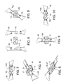
- FIG. 1 is a schematic perspective view of an embodiment of a rotary wing aircraft apparatus of the present disclosure with arms and legs in the operating position, and rotor blades installed
- FIG. 2 is a schematic perspective view of the embodiment of FIG. 1 with legs in the stored position, and rotor blades removed;
- FIG. 3 is a schematic perspective view of the embodiment of FIG. 1 with legs in the stored position, rotor blades removed, and the arms folded;
- FIG. 4 is a schematic perspective view of clockwise lock mechanism used to attach clockwise rotor blades in the embodiment of FIG. 1 with the rotor blade in the recess ready for engagement or removal;
- FIG. 5 is a schematic perspective view of clockwise lock mechanism of FIG. 4 with the rotor blade engaged and locked in the lock mechanism;
- FIG. 6 is a top view of the shaft lock portion of a counterclockwise lock mechanism with a counterclockwise rotor blade on one side and a clockwise rotor blade on the other side;
- FIG. 7 shows the counterclockwise rotor blade installed in the shaft lock portion of the counterclockwise lock mechanism of FIG. 6 ;
- FIG. 8 shows the clockwise rotor blade blocked from engagement and installation in the shaft lock portion of the counterclockwise lock mechanism of FIG. 6 ;
- FIG. 9 is a top view of the shaft lock portion of a clockwise lock mechanism with a clockwise rotor blade in the recess ready for engagement or removal;
- FIG. 10 shows the clockwise rotor blade of FIG. 9 installed in the shaft lock portion of the clockwise lock mechanism
- FIGS. 11 and 12 show respectively perspective and side views of a leg of the embodiment of FIG. 1 in the operating position
- FIGS. 13 and 14 show respectively perspective and side views of the leg of FIGS. 11 and 12 in the stored position
- FIG. 15 is a schematic cut away side view of a leg latch mechanism for operating the legs of the embodiment of FIG. 1 , with the leg in the stored position;
- FIG. 16 is a schematic cut away side view of the leg latch mechanism of FIG. 15 with the leg in the operating position but not yet engaged in the recess and thus not latched;
- FIG. 17 is a schematic cut away side view of the leg latch mechanism of FIG. 15 with the leg in the operating position and latched.
- FIGS. 1-3 schematically illustrate an embodiment of a rotary wing aircraft apparatus 1 of the present disclosure.
- the apparatus 1 comprises a body 3 , and a plurality of arms 5 extending laterally from the body 3 .
- a rotor assembly 7 is attached to an outside end of each arm 5 .
- Each rotor assembly 7 comprises a rotor blade 9 releasably attached to a driveshaft by a lock mechanism 11 , and a drive, typically an electric motor, rotating the driveshaft.
- FIG. 2 shows the apparatus 1 with rotor blades removed and support legs in the stored position as described further below.
- the arms 5 are movably attached to the body 3 such that the arms 5 can be moved from a flying position illustrated in FIG. 1 , where the arms extend forward and rearward laterally outward from the body 3 such that the arms 5 are substantially equally spaced, to a folded stored position illustrated in FIG. 3 where the arms are generally aligned with and adjacent to each other.
- the illustrated apparatus 1 has four arms 5 and corresponding rotor assemblies 7 , and as is known in the art, two of the rotor blades 9 A, 9 B rotate in a clockwise direction and generate a vertical lift force when rotated in the clockwise direction, while the other two rotor blades 9 C, 9 D rotate in a counterclockwise direction and generate a vertical lift force when rotated in the clockwise direction.
- FIGS. 4-10 The operation of the lock mechanisms 11 is illustrated in FIGS. 4-10 .
- Each clockwise rotor blade 9 A, 9 B is releasably attached to the corresponding driveshaft 13 by engagement in a clockwise lock mechanism 11 AB and each counterclockwise rotor blade 9 C, 9 D is releasably attached to the corresponding driveshaft 13 by engagement in a counterclockwise lock mechanism 11 CD.
- the rotor blades 9 must be mounted to driveshafts that are rotating in the correct direction. To ensure that the correct positioning, the clockwise rotor blades 9 A, 9 B are engageable only with the clockwise lock mechanisms 11 AB and cannot be engaged in the counterclockwise lock mechanisms 11 CD, and similarly the counterclockwise rotor blades 9 C, 9 D are engageable only with the counterclockwise lock mechanisms 11 CD and cannot be engaged in the clockwise lock mechanisms 11 AB.
- Each clockwise lock mechanism 11 AB comprises a shaft lock portion 15 A attached to the corresponding clockwise rotating driveshaft and a blade lock portion 17 A attached to the clockwise rotor blade 9 A, 9 B.
- each counterclockwise lock mechanism 11 CD comprises a shaft lock portion 15 C attached to the corresponding counterclockwise rotating driveshaft and a blade lock portion 17 C attached to the counterclockwise rotor blade 9 C, 9 D.
- FIGS. 4 and 5 show the operation of the lock mechanisms 11 .
- a clockwise lock mechanism 11 A is illustrated with the shaft lock portion 15 A attached to a clockwise rotating driveshaft 13 .
- Arrows on the shaft lock portion 15 A indicate the rotational direction, and the shaft lock portion defines a recess 21 in the middle between the arrows.
- the blade lock portion 17 A of the lock mechanism 11 A on the clockwise rotor blade 9 A is dropped into the recess 21 as seen in FIG.
- the blade lock portion 17 A of the clockwise lock mechanisms 11 A are rotated counterclockwise with respect to the shaft lock portion 15 A thereof to push the blade into the slots 23 to releasably attach the clockwise rotor blade 9 A to the shaft lock portion 15 A and thus to the driveshaft 13 .
- the shaft lock portion 15 A exerts a force in the direction of the arrows on the rotor blade to rotate same, and this force keeps the blade engaged in the slots 23 .
- the counterclockwise lock mechanism 11 C operates in a similar fashion with an opposite spin direction.
- FIG. 6 shows the shaft lock portion 15 C, with recess 21 , of a counterclockwise lock mechanism with a counterclockwise rotor blade 9 C, with blade lock portion 17 C, on one side and a clockwise rotor blade 9 A, with blade lock portion 17 A, on the other side.
- FIG. 7 shows the blade lock portion 17 C of the counterclockwise rotor blade 9 C successfully installed in the shaft lock portion 15 C to form a counterclockwise lock mechanism 11 CD.
- FIG. 8 shows that the blade lock portion 17 A of the clockwise rotor blade 9 A is prevented from rotating in direction R as required by contact of the lugs 17 A with the oppositely configured notches 27 C of the shaft lock portion 15 C.
- the clockwise rotor blades 9 A, 9 B cannot be installed on the shaft lock portion 15 C of a counterclockwise lock mechanism, and similarly the counterclockwise rotor blades 9 C, 9 D cannot be installed on the shaft lock portion 15 A of a clockwise lock mechanism.
- FIG. 9 shows the blade lock portion 17 A of the clockwise rotor blade 9 A placed in the recess 21 of a correctly selected clockwise shaft lock portion 15 A
- FIG. 10 shows the blade lock portion 17 A successfully installed in the shaft lock portion 15 A to form a clockwise lock mechanism 11 AB.
- each rotor assembly 7 has a leg 31 pivotally attached to a bottom portion of the rotor assembly 7 , as illustrated in FIGS. 11-17 .
- Each leg 31 is movable from a stored position as illustrated in FIG. 2 , where the leg 31 extends laterally from the rotor assembly 7 along the arm 5 supporting the rotor assembly, to an operating position as illustrated in FIG. 1 , where the leg extends downward from the rotor assembly 7 .
- the bottom ends of the legs 31 in the operating position are much farther apart than would be practical with a leg structure mounted to the body 3 .
- the apparatus can thus land on a considerable slope if necessary.
- the legs 31 are made from a strong yet light and somewhat flexible material to cushion the apparatus 1 on landing.
- a carbon-fiber-reinforced polymer material could be used for example. While stationary legs as shown in FIG. 1 provide increased stability, same are awkward for storage and transport, and interfere with folding arms.
- each leg 31 is therefore is pivotally attached to the bottom portion of the rotor assembly 7 such that the leg is movable from a stored position, where the leg 31 extends laterally from the rotor assembly 7 along the arm 5 supporting the rotor assembly 7 , to an operating position where the leg 31 extends downward from the rotor assembly 7 .
- FIGS. 11 and 12 show one of the legs in the operating position, where the leg 31 slopes from the rotor assembly 7 downward and away from the body at the opposite inner end of the arm 5 .
- FIGS. 13 and 14 show the leg 31 in the stored position, where a saddle 33 on the bottom end of the leg 31 engages the arm 5 to reduce the risk that the leg 31 may be forced laterally and damaged during transport to a use site.
- each leg 31 is pivotally attached to the bottom of the rotor assembly 7 about a pivot axis PA that is substantially perpendicular to the arm 5 .
- a bias element illustrated as spring 35 , urges the leg 31 toward the stored position shown in FIG. 1 .
- the operator pivots the leg 31 against the bias force BF to the operating position shown in FIG. 16 , where the upper end of the leg 31 is aligned with a recess 37 in the rotor assembly 7 and the bias force BF draws the leg into the recess 37 .
- the end of the leg 31 in the recess 37 acts then as a latch to lock the leg 31 in the operating position.
- the rotor blades of the illustrated apparatus 1 can be easily detached for transport of storage, and cannot be placed on driveshafts rotating the wrong direction.
- the legs extending down from the rotor assemblies significantly increase stability allowing the apparatus 1 to land on a steep slope without falling over and becoming inoperative.
- the legs can also be conveniently folded for storage.
Abstract
Description
- This application claims priority to Canadian Patent Application No. 2815885 filed May 15, 2013, the entire content of which is hereby incorporated by reference.
- This disclosure relates to the field of unmanned rotary aircraft or helicopters and more particularly rotary aircraft with a compact storage configuration.
- Unmanned remote control rotary aircraft have recently become popular for recreation and also in larger and more sophisticated versions for surveillance by military and police personnel. One popular configuration includes a number of arms extending laterally from the aircraft body, with a rotor assembly on the end of each arm. The rotor assemblies sometimes have upper and lower rotors that rotate in opposite directions to avoid exerting torque on the body which would cause it to spin.
- Where the rotor assemblies have a single rotor, torque on the body from the rotational motion of the rotors is avoided by having the rotors rotate in opposite directions. The vertical lift is the same, but the torque imparted by rotation in one direction is cancelled out by the rotation in the opposite direction. Where an even number of arms and rotor assemblies is used, the rotational forces cancel each other and the body is substantially stable.
- Where an uneven number of arms and rotor assemblies is used, such as in the popular three rotor configuration, two rotors spin in one direction and the third spins in the opposite direction. The rotational axis of the third rotor is then tilted slightly away from vertical so it exerts a horizontal force component that counteracts the torque force exerted by the other rotors, again resulting in a stable body. The degree of tilt can be adjusted by rotating the arm to adjust for varying rotor speeds.
- Such multi-rotor unmanned remote control rotary aircraft are disclosed for example in U.S. Pat. Nos. 8,052,081 and 8,292,215 to the present inventors Olm et al. To make the aircraft more compact for storage and transport the rotors can be removed and the arms folded into a side by side orientation. Although not shown in the patents, a leg assembly is typically attached to the bottom of the aircraft body, and to support the aircraft on the ground in the necessary orientation for landing and takeoff.
- The present disclosure provides a rotary aircraft apparatus that overcomes problems in the prior art.
- In a first embodiment the present disclosure provides a rotary wing aircraft apparatus comprising a body, a plurality of arms extending laterally from the body, and a rotor assembly attached to an outside end of each arm. Each rotor assembly comprises a rotor blade releasably attached to a driveshaft by a lock mechanism, and a drive rotating the driveshaft. A first driveshaft rotates in a clockwise direction and a second driveshaft rotates in a counterclockwise direction. A clockwise rotor blade is releasably attached to the first driveshaft by engagement in a clockwise lock mechanism and generates a vertical lift force when rotated in the clockwise direction, and a counterclockwise rotor blade is releasably attached to the second driveshaft by engagement in a counterclockwise lock mechanism and generates a vertical lift force when rotated in the counterclockwise direction. The clockwise rotor blade is engageable only with the clockwise lock mechanism and cannot be engaged in the counterclockwise lock mechanism, and the counterclockwise rotor blade is engageable only with the counterclockwise lock mechanism and cannot be engaged in the clockwise lock mechanism.
- In a second embodiment the present disclosure provides a rotary wing aircraft apparatus comprising a body, a plurality of arms extending laterally from the body, and a rotor assembly attached to an outside end of each arm, each rotor assembly comprising a rotor blade and a drive operative to rotate the rotor blade. Each rotor assembly comprises a leg extending downward from a bottom portion of the rotor assembly to support the apparatus on a ground surface.
- The rotor blades can be easily detached for transport of storage, and cannot be placed on driveshafts rotating the wrong direction. Legs extending down from the rotor assemblies increase stability allowing landing upright and operational on steep slopes. The legs can also be conveniently folded for storage.
- While the invention is claimed in the concluding portions hereof, preferred embodiments are provided in the accompanying detailed description which may be best understood in conjunction with the accompanying diagrams where like parts in each of the several diagrams are labeled with like numbers, and where:
-
FIG. 1 is a schematic perspective view of an embodiment of a rotary wing aircraft apparatus of the present disclosure with arms and legs in the operating position, and rotor blades installed -
FIG. 2 is a schematic perspective view of the embodiment ofFIG. 1 with legs in the stored position, and rotor blades removed; -
FIG. 3 is a schematic perspective view of the embodiment ofFIG. 1 with legs in the stored position, rotor blades removed, and the arms folded; -
FIG. 4 is a schematic perspective view of clockwise lock mechanism used to attach clockwise rotor blades in the embodiment ofFIG. 1 with the rotor blade in the recess ready for engagement or removal; -
FIG. 5 is a schematic perspective view of clockwise lock mechanism ofFIG. 4 with the rotor blade engaged and locked in the lock mechanism; -
FIG. 6 is a top view of the shaft lock portion of a counterclockwise lock mechanism with a counterclockwise rotor blade on one side and a clockwise rotor blade on the other side; -
FIG. 7 shows the counterclockwise rotor blade installed in the shaft lock portion of the counterclockwise lock mechanism ofFIG. 6 ; -
FIG. 8 shows the clockwise rotor blade blocked from engagement and installation in the shaft lock portion of the counterclockwise lock mechanism ofFIG. 6 ; -
FIG. 9 is a top view of the shaft lock portion of a clockwise lock mechanism with a clockwise rotor blade in the recess ready for engagement or removal; -
FIG. 10 shows the clockwise rotor blade ofFIG. 9 installed in the shaft lock portion of the clockwise lock mechanism; -
FIGS. 11 and 12 show respectively perspective and side views of a leg of the embodiment ofFIG. 1 in the operating position; -
FIGS. 13 and 14 show respectively perspective and side views of the leg ofFIGS. 11 and 12 in the stored position; -
FIG. 15 is a schematic cut away side view of a leg latch mechanism for operating the legs of the embodiment ofFIG. 1 , with the leg in the stored position; -
FIG. 16 is a schematic cut away side view of the leg latch mechanism ofFIG. 15 with the leg in the operating position but not yet engaged in the recess and thus not latched; -
FIG. 17 is a schematic cut away side view of the leg latch mechanism ofFIG. 15 with the leg in the operating position and latched. -
FIGS. 1-3 schematically illustrate an embodiment of a rotarywing aircraft apparatus 1 of the present disclosure. Theapparatus 1 comprises abody 3, and a plurality ofarms 5 extending laterally from thebody 3. Arotor assembly 7 is attached to an outside end of eacharm 5. Eachrotor assembly 7 comprises a rotor blade 9 releasably attached to a driveshaft by a lock mechanism 11, and a drive, typically an electric motor, rotating the driveshaft. -
FIG. 2 shows theapparatus 1 with rotor blades removed and support legs in the stored position as described further below. In the illustratedapparatus 1 thearms 5 are movably attached to thebody 3 such that thearms 5 can be moved from a flying position illustrated inFIG. 1 , where the arms extend forward and rearward laterally outward from thebody 3 such that thearms 5 are substantially equally spaced, to a folded stored position illustrated inFIG. 3 where the arms are generally aligned with and adjacent to each other. - The illustrated
apparatus 1 has fourarms 5 andcorresponding rotor assemblies 7, and as is known in the art, two of therotor blades rotor blades - The operation of the lock mechanisms 11 is illustrated in
FIGS. 4-10 . Each clockwiserotor blade corresponding driveshaft 13 by engagement in a clockwise lock mechanism 11AB and eachcounterclockwise rotor blade corresponding driveshaft 13 by engagement in a counterclockwise lock mechanism 11CD. - It will be appreciated that in order for the
apparatus 1 to operate properly, the rotor blades 9 must be mounted to driveshafts that are rotating in the correct direction. To ensure that the correct positioning, theclockwise rotor blades counterclockwise rotor blades - Each clockwise lock mechanism 11AB comprises a
shaft lock portion 15A attached to the corresponding clockwise rotating driveshaft and ablade lock portion 17A attached to theclockwise rotor blade shaft lock portion 15C attached to the corresponding counterclockwise rotating driveshaft and ablade lock portion 17C attached to thecounterclockwise rotor blade -
FIGS. 4 and 5 show the operation of the lock mechanisms 11. A clockwise lock mechanism 11A is illustrated with theshaft lock portion 15A attached to a clockwise rotatingdriveshaft 13. Arrows on theshaft lock portion 15A indicate the rotational direction, and the shaft lock portion defines arecess 21 in the middle between the arrows. Theblade lock portion 17A of the lock mechanism 11A on theclockwise rotor blade 9A is dropped into therecess 21 as seen inFIG. 4 and therotor blade 9A is then rotated in direction R opposite to the direction of the arrows such that theblade 9A slides intoslots 23 on each side of theshaft lock portion 15A under the arrows, and lugs 25A on theblade lock portion 17A engage notches 27A defined by the shaft lock portion as seen inFIG. 5 . - The
blade lock portion 17A of the clockwise lock mechanisms 11A are rotated counterclockwise with respect to theshaft lock portion 15A thereof to push the blade into theslots 23 to releasably attach theclockwise rotor blade 9A to theshaft lock portion 15A and thus to thedriveshaft 13. During operation theshaft lock portion 15A exerts a force in the direction of the arrows on the rotor blade to rotate same, and this force keeps the blade engaged in theslots 23. The counterclockwise lock mechanism 11C operates in a similar fashion with an opposite spin direction. -
FIG. 6 shows theshaft lock portion 15C, withrecess 21, of a counterclockwise lock mechanism with acounterclockwise rotor blade 9C, withblade lock portion 17C, on one side and aclockwise rotor blade 9A, withblade lock portion 17A, on the other side.FIG. 7 shows theblade lock portion 17C of thecounterclockwise rotor blade 9C successfully installed in theshaft lock portion 15C to form a counterclockwise lock mechanism 11CD. -
FIG. 8 shows that theblade lock portion 17A of theclockwise rotor blade 9A is prevented from rotating in direction R as required by contact of thelugs 17A with the oppositely configured notches 27C of theshaft lock portion 15C. Thus theclockwise rotor blades shaft lock portion 15C of a counterclockwise lock mechanism, and similarly thecounterclockwise rotor blades shaft lock portion 15A of a clockwise lock mechanism. -
FIG. 9 shows theblade lock portion 17A of theclockwise rotor blade 9A placed in therecess 21 of a correctly selected clockwiseshaft lock portion 15A, andFIG. 10 shows theblade lock portion 17A successfully installed in theshaft lock portion 15A to form a clockwise lock mechanism 11AB. - Commonly in the prior art the rotary aircraft is supported on a leg structure attached under the body. Stability of the aircraft on the ground is improved in
present apparatus 1 where eachrotor assembly 7 has aleg 31 pivotally attached to a bottom portion of therotor assembly 7, as illustrated inFIGS. 11-17 . Eachleg 31 is movable from a stored position as illustrated inFIG. 2 , where theleg 31 extends laterally from therotor assembly 7 along thearm 5 supporting the rotor assembly, to an operating position as illustrated inFIG. 1 , where the leg extends downward from therotor assembly 7. - It can be seen in Fig. that the bottom ends of the
legs 31 in the operating position are much farther apart than would be practical with a leg structure mounted to thebody 3. The apparatus can thus land on a considerable slope if necessary. Beneficially thelegs 31 are made from a strong yet light and somewhat flexible material to cushion theapparatus 1 on landing. A carbon-fiber-reinforced polymer material could be used for example. While stationary legs as shown inFIG. 1 provide increased stability, same are awkward for storage and transport, and interfere with folding arms. - In the
illustrated apparatus 1 eachleg 31 is therefore is pivotally attached to the bottom portion of therotor assembly 7 such that the leg is movable from a stored position, where theleg 31 extends laterally from therotor assembly 7 along thearm 5 supporting therotor assembly 7, to an operating position where theleg 31 extends downward from therotor assembly 7. -
FIGS. 11 and 12 show one of the legs in the operating position, where theleg 31 slopes from therotor assembly 7 downward and away from the body at the opposite inner end of thearm 5.FIGS. 13 and 14 show theleg 31 in the stored position, where a saddle 33 on the bottom end of theleg 31 engages thearm 5 to reduce the risk that theleg 31 may be forced laterally and damaged during transport to a use site. - In the
illustrated apparatus 1, as seen inFIGS. 15-17 , eachleg 31 is pivotally attached to the bottom of therotor assembly 7 about a pivot axis PA that is substantially perpendicular to thearm 5. A bias element, illustrated asspring 35, urges theleg 31 toward the stored position shown inFIG. 1 . To move to the operating position, the operator pivots theleg 31 against the bias force BF to the operating position shown inFIG. 16 , where the upper end of theleg 31 is aligned with arecess 37 in therotor assembly 7 and the bias force BF draws the leg into therecess 37. The end of theleg 31 in therecess 37 acts then as a latch to lock theleg 31 in the operating position. - The rotor blades of the
illustrated apparatus 1 can be easily detached for transport of storage, and cannot be placed on driveshafts rotating the wrong direction. The legs extending down from the rotor assemblies significantly increase stability allowing theapparatus 1 to land on a steep slope without falling over and becoming inoperative. The legs can also be conveniently folded for storage. - The foregoing is considered as illustrative only of the principles of the invention. Further, since numerous changes and modifications will readily occur to those skilled in the art, it is not desired to limit the invention to the exact construction and operation shown and described, and accordingly, all such suitable changes or modifications in structure or operation which may be resorted to are intended to fall within the scope of the claimed invention.
Claims (20)
Applications Claiming Priority (2)
| Application Number | Priority Date | Filing Date | Title |
|---|---|---|---|
| CA2815885A CA2815885C (en) | 2013-05-15 | 2013-05-15 | Compact unmanned rotary aircraft |
| CA2815885 | 2014-02-04 |
Publications (2)
| Publication Number | Publication Date |
|---|---|
| US20140339355A1 true US20140339355A1 (en) | 2014-11-20 |
| US9260184B2 US9260184B2 (en) | 2016-02-16 |
Family
ID=51894322
Family Applications (1)
| Application Number | Title | Priority Date | Filing Date |
|---|---|---|---|
| US14/277,370 Active US9260184B2 (en) | 2013-05-15 | 2014-05-14 | Compact unmanned rotary aircraft |
Country Status (2)
| Country | Link |
|---|---|
| US (1) | US9260184B2 (en) |
| CA (3) | CA2815885C (en) |
Cited By (89)
| Publication number | Priority date | Publication date | Assignee | Title |
|---|---|---|---|---|
| CN104743132A (en) * | 2015-04-17 | 2015-07-01 | 浙江工业职业技术学院 | Aerial photography device |
| US20150259066A1 (en) * | 2012-10-19 | 2015-09-17 | Aeryon Labs Inc. | Hovering unmanned aerial vehicle |
| US20150274286A1 (en) * | 2014-03-30 | 2015-10-01 | Yefim Kereth | Asymmetric multirotor helicopter |
| CN105059528A (en) * | 2015-07-23 | 2015-11-18 | 致导科技(北京)有限公司 | Foldable unmanned aerial vehicle |
| US20160023759A1 (en) * | 2014-07-25 | 2016-01-28 | Ronald M. Barrett | Movable member bearing aerial vehicles and methods of use |
| CN105314101A (en) * | 2015-10-27 | 2016-02-10 | 重庆光煦科技有限公司 | Folding multi-rotor-wing plant protection unmanned plane |
| USD766159S1 (en) * | 2015-08-27 | 2016-09-13 | Skycatch, Inc. | Landing gear for an unmanned aerial vehicle |
| US20160272316A1 (en) * | 2015-01-17 | 2016-09-22 | Brian Dale Nelson | Multicopter with Detachable Wing |
| US9456185B2 (en) | 2009-08-26 | 2016-09-27 | Geotech Environmental Equipment, Inc. | Helicopter |
| CN105980250A (en) * | 2015-05-14 | 2016-09-28 | 深圳市大疆创新科技有限公司 | Landing gear and an unmanned aerial vehicle using the landing gear |
| USD768539S1 (en) * | 2015-08-04 | 2016-10-11 | Gopro, Inc. | Aerial vehicle |
| USD768540S1 (en) * | 2015-04-14 | 2016-10-11 | By Robot Co., Ltd. | Unmanned flying robot |
| CN106275407A (en) * | 2016-09-20 | 2017-01-04 | 东莞飞侠智能科技股份有限公司 | A kind of wing of collapsible unmanned plane |
| USD777059S1 (en) * | 2015-05-15 | 2017-01-24 | SZ DJI Technology Co., Ltd. | Unmanned aerial vehicle |
| USD777263S1 (en) * | 2015-04-05 | 2017-01-24 | Parrot Drones | Remote-controlled toy |
| CN106347625A (en) * | 2016-10-26 | 2017-01-25 | 成都市优艾维机器人科技有限公司 | Unmanned aerial vehicle linkage folding mechanism |
| USD778371S1 (en) * | 2015-09-28 | 2017-02-07 | Traxxas Lp | Roll hoop for a quadrotor model helicopter |
| CN106394864A (en) * | 2016-09-14 | 2017-02-15 | 北京博瑞空间科技发展有限公司 | Folding support structure and unmanned aerial vehicle |
| USD780062S1 (en) * | 2015-06-01 | 2017-02-28 | SZ DJI Technology Co., Ltd. | Unmanned aerial vehicle |
| WO2017039233A1 (en) * | 2015-09-01 | 2017-03-09 | 한국항공우주연구원 | Drone capable of varying propeller arrangement shape |
| US9616998B2 (en) | 2010-08-26 | 2017-04-11 | Geotech Environmental Equipment, Inc. | Unmanned aerial vehicle/unmanned aircraft system |
| USD783727S1 (en) * | 2016-04-06 | 2017-04-11 | Guangdong Syma Model Aircraft Industrial Co., Ltd | Toy aircraft |
| USD784202S1 (en) * | 2015-10-16 | 2017-04-18 | Hanwha Techwin Co., Ltd. | Unmanned aerial vehicle |
| USD784854S1 (en) * | 2015-11-02 | 2017-04-25 | Shenzhen Rapoo Technology Co., Ltd. | Unmanned aircraft |
| USD785717S1 (en) * | 2016-03-31 | 2017-05-02 | Guangdong Syma Model Aircraft Industrial Co., Ltd | Toy aircraft |
| WO2017107751A1 (en) * | 2015-12-25 | 2017-06-29 | 广州亿航智能技术有限公司 | Drone |
| JP2017128258A (en) * | 2016-01-21 | 2017-07-27 | 株式会社松田康利事務所 | Rotor and multicopter |
| USD798963S1 (en) * | 2016-11-04 | 2017-10-03 | Guangdong Syma Model Aircraft Industrial Co., Ltd. | Aircraft toy |
| USD798962S1 (en) * | 2016-11-04 | 2017-10-03 | Guangdong Syma Model Aircraft Industrial Co., Ltd. | Aircraft toy |
| US20170327230A1 (en) * | 2013-04-02 | 2017-11-16 | Hood Technology Corporation | Multicopter-assisted system and method for launching and retrieving a fixed-wing aircraft |
| CN107364584A (en) * | 2017-07-27 | 2017-11-21 | 钱月珍 | Unmanned plane fall protection system |
| USD803328S1 (en) | 2015-12-18 | 2017-11-21 | Gopro, Inc. | Aerial vehicle |
| CN107444622A (en) * | 2016-05-31 | 2017-12-08 | 比亚迪股份有限公司 | For unmanned plane landing gear assembly and there is its unmanned plane |
| CN107531322A (en) * | 2015-04-21 | 2018-01-02 | 高途乐公司 | Aerial capture platform |
| USD808301S1 (en) * | 2016-08-22 | 2018-01-23 | Trend Right Research And Development Corporation | Unmanned aerial vehicle |
| US9875251B2 (en) | 2015-06-02 | 2018-01-23 | GeoFrenzy, Inc. | Geofence information delivery systems and methods |
| US9906902B2 (en) | 2015-06-02 | 2018-02-27 | GeoFrenzy, Inc. | Geofence information delivery systems and methods |
| US9906905B2 (en) | 2015-06-02 | 2018-02-27 | GeoFrenzy, Inc. | Registration mapping toolkit for geofences |
| US9906609B2 (en) | 2015-06-02 | 2018-02-27 | GeoFrenzy, Inc. | Geofence information delivery systems and methods |
| US9938009B2 (en) | 2013-08-15 | 2018-04-10 | Traxxas Lp | Rotorcraft with integrated light pipe support members |
| US9986378B2 (en) | 2014-07-29 | 2018-05-29 | GeoFrenzy, Inc. | Systems and methods for defining and implementing rules for three dimensional geofences |
| US20180237132A1 (en) * | 2015-08-12 | 2018-08-23 | Shanghai Fukun Aviation Technology Co., Ltd. | Vertical take-off and landing fixed-wing aircraft and the flight control method thereof |
| USD827723S1 (en) * | 2015-09-28 | 2018-09-04 | Traxxas Lp | Quadrotor model helicopter |
| USD827724S1 (en) * | 2015-09-28 | 2018-09-04 | Traxxas Lp | Set of supporting arms for a quadrotor model helicopter |
| WO2018182883A1 (en) * | 2017-03-31 | 2018-10-04 | Qualcomm Incorporated | Double folding drone arms with landing gear |
| USD830281S1 (en) * | 2017-09-05 | 2018-10-09 | North American Wave Engine Corporation | Unmanned vertical takeoff and landing vehicle |
| US10115277B2 (en) | 2014-07-29 | 2018-10-30 | GeoFrenzy, Inc. | Systems and methods for geofence security |
| US10118697B2 (en) * | 2015-06-25 | 2018-11-06 | Riderless Technologies Inc. | Unmanned aerial vehicle |
| CN108750068A (en) * | 2015-04-08 | 2018-11-06 | 深圳市大疆创新科技有限公司 | Aircraft |
| US10121215B2 (en) | 2014-07-29 | 2018-11-06 | GeoFrenzy, Inc. | Systems and methods for managing real estate titles and permissions |
| WO2018025122A3 (en) * | 2016-08-01 | 2018-11-08 | Heaney Jonathan Michael | Damage mitigating, modular system for multirotor airframes |
| CN109070999A (en) * | 2016-03-23 | 2018-12-21 | 亚马逊科技公司 | The coaxial alignment propeller of aircraft (AERIAL VEHICLE) |
| CN109436330A (en) * | 2018-11-08 | 2019-03-08 | 天津市澍丰农业科技有限公司 | A kind of agriculture unmanned plane support frame device and operating method of spraying |
| US10235726B2 (en) | 2013-09-24 | 2019-03-19 | GeoFrenzy, Inc. | Systems and methods for secure encryption of real estate titles and permissions |
| US10237232B2 (en) | 2014-07-29 | 2019-03-19 | GeoFrenzy, Inc. | Geocoding with geofences |
| US20190168871A1 (en) * | 2014-12-18 | 2019-06-06 | Gopro, Inc. | Self-enclosed air vehicle |
| US10375514B2 (en) | 2014-07-29 | 2019-08-06 | GeoFrenzy, Inc. | Systems, methods and apparatus for geofence networks |
| CN110155314A (en) * | 2019-05-13 | 2019-08-23 | 北京遥感设备研究所 | A kind of six rotor wing unmanned aerial vehicles |
| US10407162B2 (en) * | 2014-01-20 | 2019-09-10 | Robodub Inc. | Multicopters with variable flight characteristics |
| US10473058B2 (en) | 2015-03-19 | 2019-11-12 | North American Wave Engine Corporation | Systems and methods for improving operation of pulse combustors |
| US20200001990A1 (en) * | 2017-03-15 | 2020-01-02 | SZ DJI Technology Co., Ltd. | Automatically and releasably coupling uav propellers to propulsion motors, and associated systems and methods |
| US10549850B1 (en) | 2016-05-08 | 2020-02-04 | Redd, Llc | Portable multithruster unmanned aircraft |
| US10557438B2 (en) | 2015-12-18 | 2020-02-11 | North American Wave Engine Corporation | Systems and methods for air-breathing wave engines for thrust production |
| US10582333B2 (en) | 2014-07-29 | 2020-03-03 | GeoFrenzy, Inc. | Systems and methods for geofence security |
| US10632804B2 (en) | 2015-06-01 | 2020-04-28 | Imperial College Innovations Limited | Robotic vehicle |
| US10696414B2 (en) | 2015-04-21 | 2020-06-30 | Gopro, Inc. | Aerial capture platform |
| US10730615B2 (en) | 2013-04-02 | 2020-08-04 | Hood Technology Corporation | Multicopter-assisted system and method for launching and retrieving a fixed-wing aircraft |
| US10805761B2 (en) | 2014-07-29 | 2020-10-13 | GeoFrenzy, Inc. | Global registration system for aerial vehicles |
| CN112224392A (en) * | 2020-10-14 | 2021-01-15 | 湖南库里斯智能科技有限公司 | High-stability starting unmanned aerial vehicle |
| US10932084B2 (en) | 2014-07-29 | 2021-02-23 | GeoFrenzy, Inc. | Systems, methods and apparatus for geofence networks |
| US10946959B2 (en) * | 2018-10-09 | 2021-03-16 | Arizechukwu Nwosu | Drone configured for multiple uses |
| US10979849B2 (en) | 2015-06-02 | 2021-04-13 | GeoFrenzy, Inc. | Systems, methods and apparatus for geofence networks |
| US10988257B2 (en) * | 2017-05-11 | 2021-04-27 | Hood Technology Corporation | Aircraft-retrieval system |
| US11141673B1 (en) | 2016-09-28 | 2021-10-12 | Traxxas Lp | Model rotorcraft with light pipe support members |
| US20210339855A1 (en) * | 2019-10-09 | 2021-11-04 | Kitty Hawk Corporation | Hybrid power systems for different modes of flight |
| US11240628B2 (en) | 2014-07-29 | 2022-02-01 | GeoFrenzy, Inc. | Systems and methods for decoupling and delivering geofence geometries to maps |
| US11235892B2 (en) | 2019-05-22 | 2022-02-01 | Hood Technology Corporation | Aircraft retrieval system and method |
| US11260972B2 (en) * | 2018-01-24 | 2022-03-01 | Arizona Board Of Regents On Behalf Of Arizona State University | Systems and methods for a foldable unmanned aerial vehicle having a laminate structure |
| US20220073204A1 (en) * | 2015-11-10 | 2022-03-10 | Matternet, Inc. | Methods and systems for transportation using unmanned aerial vehicles |
| US20220315218A1 (en) * | 2019-12-27 | 2022-10-06 | Zhejiang University | Underwater and aerial vehicle |
| US11524797B2 (en) | 2017-05-11 | 2022-12-13 | Hood Technology Corporation | Aircraft-retrieval system |
| US20230001757A1 (en) * | 2019-11-22 | 2023-01-05 | Northeastern University | Morpho-functional robots with legged and aerial modes of locomotion |
| US11575648B2 (en) | 2014-07-29 | 2023-02-07 | GeoFrenzy, Inc. | Geocoding with geofences |
| US11578681B2 (en) | 2015-03-19 | 2023-02-14 | University Of Maryland | Systems and methods for anti-phase operation of pulse combustors |
| US11585532B2 (en) | 2018-04-17 | 2023-02-21 | North American Wave Engine Corporation | Method and apparatus for the start-up and control of pulse combustors using selective injector operation |
| US11591076B2 (en) * | 2019-06-26 | 2023-02-28 | Toyota Motor Engineering & Manufacturing North America, Inc. | Inflatable drone with shape memory alloy wires |
| US11606666B2 (en) | 2014-07-29 | 2023-03-14 | GeoFrenzy, Inc. | Global registration system for aerial vehicles |
| DE102021132911A1 (en) | 2021-12-14 | 2023-06-15 | Dr. Ing. H.C. F. Porsche Aktiengesellschaft | Lift unit for an aircraft and aircraft with such a lift unit |
| US11838744B2 (en) | 2014-07-29 | 2023-12-05 | GeoFrenzy, Inc. | Systems, methods and apparatus for geofence networks |
Families Citing this family (29)
| Publication number | Priority date | Publication date | Assignee | Title |
|---|---|---|---|---|
| CN103921933A (en) | 2013-01-10 | 2014-07-16 | 深圳市大疆创新科技有限公司 | Deformation structure of air vehicle and micro air vehicle |
| CN203306224U (en) | 2013-05-31 | 2013-11-27 | 深圳市大疆创新科技有限公司 | Propeller and aircraft provided with same |
| JP6232148B2 (en) | 2014-06-26 | 2017-11-15 | エスゼット ディージェイアイ テクノロジー カンパニー リミテッドSz Dji Technology Co.,Ltd | Airplane and its signal line protection assembly |
| USD784201S1 (en) * | 2015-05-07 | 2017-04-18 | Robert Goldy | Unmanned aerial vehicle |
| EP3892535A1 (en) * | 2015-06-01 | 2021-10-13 | SZ DJI Technology Co., Ltd. | Segmented propulsion unit arm for an unmanned aerial vehicle |
| EP3419894B1 (en) * | 2016-02-22 | 2021-11-10 | SZ DJI Technology Co., Ltd. | Foldable multi-rotor aerial vehicle |
| FR3048185B1 (en) * | 2016-02-25 | 2018-03-23 | Parrot Drones | DRONE WITH FOLDING LINK ARM. |
| CN105644777A (en) * | 2016-03-17 | 2016-06-08 | 中国直升机设计研究所 | Assembly type multi-rotor aerocraft |
| KR101713669B1 (en) * | 2016-03-31 | 2017-03-08 | 한국생산기술연구원 | Drone with foldable wings |
| CN107985559A (en) * | 2016-05-19 | 2018-05-04 | 蔡留凤 | Using the unmanned plane and its method of work of infrared ray sensor |
| US10787249B2 (en) * | 2016-10-12 | 2020-09-29 | Intel Corporation | Multi-stage reduction of impact forces |
| CN206155785U (en) * | 2016-11-08 | 2017-05-10 | 深圳市大疆创新科技有限公司 | Motor and have unmanned aerial vehicle of this motor |
| CN106927018A (en) * | 2017-04-07 | 2017-07-07 | 厦门南羽科技有限公司 | A kind of foldable unmanned plane |
| USD851540S1 (en) | 2017-06-07 | 2019-06-18 | MerchSource, LLC | Drone |
| USD902078S1 (en) | 2017-06-07 | 2020-11-17 | MerchSource, LLC | Drone |
| USD825380S1 (en) | 2017-06-27 | 2018-08-14 | MerchSource, LLC | Drone for kids |
| USD825669S1 (en) | 2017-07-10 | 2018-08-14 | MerchSource, LLC | Drone car |
| USD852091S1 (en) | 2017-07-20 | 2019-06-25 | MerchSource, LLC | Drone |
| CN107416190B (en) * | 2017-07-26 | 2020-06-12 | 南京溧水高新创业投资管理有限公司 | Unmanned aerial vehicle shoots support damping device |
| CN109383739A (en) * | 2017-08-04 | 2019-02-26 | 深圳市道通智能航空技术有限公司 | A kind of horn and unmanned plane |
| USD862285S1 (en) * | 2017-08-25 | 2019-10-08 | MerchSource, LLC | Drone |
| USD846445S1 (en) | 2017-09-15 | 2019-04-23 | MerchSource, LLC | Drone |
| CN109070992B (en) * | 2017-09-30 | 2021-11-26 | 深圳市大疆创新科技有限公司 | Unmanned aerial vehicle's frame subassembly and unmanned aerial vehicle |
| USD864022S1 (en) * | 2018-03-30 | 2019-10-22 | Shenzhen Valuelink E-Commerce Co., Ltd. | Unmanned aerial vehicle |
| US11794888B1 (en) * | 2018-05-18 | 2023-10-24 | Taylor & Lego Holdings, Llc. | Unmanned aerial vehicle |
| USD873175S1 (en) * | 2018-05-23 | 2020-01-21 | Shenzhen Hubsan Technology Co., Ltd. | Drone |
| CN214986041U (en) * | 2020-11-09 | 2021-12-03 | 深圳市大疆创新科技有限公司 | Folding horn and unmanned aerial vehicle |
| CA203742S (en) * | 2020-12-15 | 2023-02-08 | Guangzhou Xaircraft Tech Co Ltd | Unmanned aerial vehicle |
| USD1017478S1 (en) * | 2022-04-12 | 2024-03-12 | SIA “InDrones” | Drone |
Citations (37)
| Publication number | Priority date | Publication date | Assignee | Title |
|---|---|---|---|---|
| US1400032A (en) * | 1919-01-16 | 1921-12-13 | Westinghouse Electric & Mfg Co | Self-tightening propeller-hub |
| US2478847A (en) * | 1944-10-06 | 1949-08-09 | Gen Motors Corp | Convertible helicopter-airplane |
| US4161843A (en) * | 1978-09-01 | 1979-07-24 | Hui Danny C T | Electrically powered toy aircraft |
| US4477228A (en) * | 1982-01-28 | 1984-10-16 | The Boeing Company | Injection molded propeller |
| US5201679A (en) * | 1991-12-13 | 1993-04-13 | Attwood Corporation | Marine propeller with breakaway hub |
| US20020104922A1 (en) * | 2000-12-08 | 2002-08-08 | Mikio Nakamura | Vertical takeoff and landing aircraft with multiple rotors |
| US20050061910A1 (en) * | 2002-03-06 | 2005-03-24 | Aloys Wobben | Aircraft |
| US7086843B2 (en) * | 2003-06-13 | 2006-08-08 | Asia Vital Components Co., Ltd. | Cooling fan hub assembly |
| US20060226281A1 (en) * | 2004-11-17 | 2006-10-12 | Walton Joh-Paul C | Ducted fan vertical take-off and landing vehicle |
| US7200982B2 (en) * | 2004-07-01 | 2007-04-10 | Briggs & Stratton Corporation | Blade slippage apparatus |
| US20080048065A1 (en) * | 2004-12-23 | 2008-02-28 | Julian Kuntz | Flying Device With Improved Movement on The Ground |
| US20090008499A1 (en) * | 2007-02-16 | 2009-01-08 | Donald Orval Shaw | Modular flying vehicle |
| US20090250549A1 (en) * | 2006-06-26 | 2009-10-08 | Burkhard Wiggerich | Aircraft |
| US20090283629A1 (en) * | 2008-05-15 | 2009-11-19 | Aeryon Labs Inc. | Hovering aerial vehicle with removable rotor arm assemblies |
| US20100044499A1 (en) * | 2008-08-22 | 2010-02-25 | Draganfly Innovations Inc. | Six rotor helicopter |
| US7699260B2 (en) * | 2005-01-14 | 2010-04-20 | Hughey Electricopter Corporation | Vertical takeoff and landing aircraft using a redundant array of independent rotors |
| US20100140415A1 (en) * | 2008-12-08 | 2010-06-10 | Honeywell International Inc. | Vertical take off and landing unmanned aerial vehicle airframe structure |
| US20100243794A1 (en) * | 2009-03-24 | 2010-09-30 | Alien Technologies Ltd | Flying apparatus |
| US20110001020A1 (en) * | 2009-07-02 | 2011-01-06 | Pavol Forgac | Quad tilt rotor aerial vehicle with stoppable rotors |
| US20110017865A1 (en) * | 2008-03-18 | 2011-01-27 | Ascending Technologies Gmbh | Rotary-Wing Aircraft |
| US20110226892A1 (en) * | 2008-08-08 | 2011-09-22 | William Crowther | Rotary wing vehicle |
| US8052081B2 (en) * | 2008-08-22 | 2011-11-08 | Draganfly Innovations Inc. | Dual rotor helicopter with tilted rotational axes |
| US20120241553A1 (en) * | 2010-07-20 | 2012-09-27 | Paul Wilke | Helicopter with two or more rotor heads |
| US20130068892A1 (en) * | 2010-06-04 | 2013-03-21 | Hazry Bin Desa | Flying apparatus for aerial agricultural application |
| US8646720B2 (en) * | 2010-05-10 | 2014-02-11 | Donald Orval Shaw | Modular flight vehicle with wings |
| US8662438B2 (en) * | 2009-11-13 | 2014-03-04 | Parrot | Navigation electronic card support for a rotary wing drone |
| US20140061362A1 (en) * | 2012-08-29 | 2014-03-06 | Draganfly Innovations Inc. | Vehicle with aerial and ground mobility |
| US8695919B2 (en) * | 2010-11-12 | 2014-04-15 | Sky Sapience Ltd. | Aerial unit and method for elevating payloads |
| US20140117149A1 (en) * | 2012-10-29 | 2014-05-01 | Shenzhen Hubsan Technology Co., Ltd | Tetra-Propeller Aircraft |
| US20140131510A1 (en) * | 2012-11-15 | 2014-05-15 | SZ DJI Technology Co., Ltd | Unmanned aerial vehicle and operations thereof |
| US20140138476A1 (en) * | 2012-11-21 | 2014-05-22 | Lapcad Engineering, Inc. | Method and means to control the position and attitude of an airborne vehicle at very low velocity |
| US20140138477A1 (en) * | 2011-03-22 | 2014-05-22 | Aerovironment Inc | Invertible aircraft |
| US8753155B2 (en) * | 2012-08-22 | 2014-06-17 | Draganfly Innovations Inc. | Wheel with folding segments |
| US8794566B2 (en) * | 2012-08-02 | 2014-08-05 | Neurosciences Research Foundation, Inc. | Vehicle capable of stabilizing a payload when in motion |
| US8794564B2 (en) * | 2012-08-02 | 2014-08-05 | Neurosciences Research Foundation, Inc. | Vehicle capable of in-air and on-ground mobility |
| US20140263823A1 (en) * | 2013-01-10 | 2014-09-18 | SZ DJI Technology Co., Ltd | Transformable aerial vehicle |
| US8919691B2 (en) * | 2010-06-08 | 2014-12-30 | Well-Head Rescue Ab | Life-saving vehicle |
-
2013
- 2013-05-15 CA CA2815885A patent/CA2815885C/en active Active
- 2013-05-15 CA CA3098531A patent/CA3098531C/en active Active
- 2013-05-15 CA CA2997790A patent/CA2997790C/en active Active
-
2014
- 2014-05-14 US US14/277,370 patent/US9260184B2/en active Active
Patent Citations (39)
| Publication number | Priority date | Publication date | Assignee | Title |
|---|---|---|---|---|
| US1400032A (en) * | 1919-01-16 | 1921-12-13 | Westinghouse Electric & Mfg Co | Self-tightening propeller-hub |
| US2478847A (en) * | 1944-10-06 | 1949-08-09 | Gen Motors Corp | Convertible helicopter-airplane |
| US4161843A (en) * | 1978-09-01 | 1979-07-24 | Hui Danny C T | Electrically powered toy aircraft |
| US4477228A (en) * | 1982-01-28 | 1984-10-16 | The Boeing Company | Injection molded propeller |
| US5201679A (en) * | 1991-12-13 | 1993-04-13 | Attwood Corporation | Marine propeller with breakaway hub |
| US20020104922A1 (en) * | 2000-12-08 | 2002-08-08 | Mikio Nakamura | Vertical takeoff and landing aircraft with multiple rotors |
| US20080006737A1 (en) * | 2002-03-06 | 2008-01-10 | Aloys Wobben | Aircraft |
| US20050061910A1 (en) * | 2002-03-06 | 2005-03-24 | Aloys Wobben | Aircraft |
| US7086843B2 (en) * | 2003-06-13 | 2006-08-08 | Asia Vital Components Co., Ltd. | Cooling fan hub assembly |
| US7200982B2 (en) * | 2004-07-01 | 2007-04-10 | Briggs & Stratton Corporation | Blade slippage apparatus |
| US20060226281A1 (en) * | 2004-11-17 | 2006-10-12 | Walton Joh-Paul C | Ducted fan vertical take-off and landing vehicle |
| US20080048065A1 (en) * | 2004-12-23 | 2008-02-28 | Julian Kuntz | Flying Device With Improved Movement on The Ground |
| US7699260B2 (en) * | 2005-01-14 | 2010-04-20 | Hughey Electricopter Corporation | Vertical takeoff and landing aircraft using a redundant array of independent rotors |
| US20090250549A1 (en) * | 2006-06-26 | 2009-10-08 | Burkhard Wiggerich | Aircraft |
| US20090008499A1 (en) * | 2007-02-16 | 2009-01-08 | Donald Orval Shaw | Modular flying vehicle |
| US20110017865A1 (en) * | 2008-03-18 | 2011-01-27 | Ascending Technologies Gmbh | Rotary-Wing Aircraft |
| US20090283629A1 (en) * | 2008-05-15 | 2009-11-19 | Aeryon Labs Inc. | Hovering aerial vehicle with removable rotor arm assemblies |
| US20110226892A1 (en) * | 2008-08-08 | 2011-09-22 | William Crowther | Rotary wing vehicle |
| US20100044499A1 (en) * | 2008-08-22 | 2010-02-25 | Draganfly Innovations Inc. | Six rotor helicopter |
| US8052081B2 (en) * | 2008-08-22 | 2011-11-08 | Draganfly Innovations Inc. | Dual rotor helicopter with tilted rotational axes |
| US20100140415A1 (en) * | 2008-12-08 | 2010-06-10 | Honeywell International Inc. | Vertical take off and landing unmanned aerial vehicle airframe structure |
| US8328130B2 (en) * | 2008-12-08 | 2012-12-11 | Honeywell International Inc. | Vertical take off and landing unmanned aerial vehicle airframe structure |
| US20100243794A1 (en) * | 2009-03-24 | 2010-09-30 | Alien Technologies Ltd | Flying apparatus |
| US20110001020A1 (en) * | 2009-07-02 | 2011-01-06 | Pavol Forgac | Quad tilt rotor aerial vehicle with stoppable rotors |
| US8662438B2 (en) * | 2009-11-13 | 2014-03-04 | Parrot | Navigation electronic card support for a rotary wing drone |
| US8646720B2 (en) * | 2010-05-10 | 2014-02-11 | Donald Orval Shaw | Modular flight vehicle with wings |
| US20130068892A1 (en) * | 2010-06-04 | 2013-03-21 | Hazry Bin Desa | Flying apparatus for aerial agricultural application |
| US8919691B2 (en) * | 2010-06-08 | 2014-12-30 | Well-Head Rescue Ab | Life-saving vehicle |
| US20120241553A1 (en) * | 2010-07-20 | 2012-09-27 | Paul Wilke | Helicopter with two or more rotor heads |
| US8695919B2 (en) * | 2010-11-12 | 2014-04-15 | Sky Sapience Ltd. | Aerial unit and method for elevating payloads |
| US20140138477A1 (en) * | 2011-03-22 | 2014-05-22 | Aerovironment Inc | Invertible aircraft |
| US8794566B2 (en) * | 2012-08-02 | 2014-08-05 | Neurosciences Research Foundation, Inc. | Vehicle capable of stabilizing a payload when in motion |
| US8794564B2 (en) * | 2012-08-02 | 2014-08-05 | Neurosciences Research Foundation, Inc. | Vehicle capable of in-air and on-ground mobility |
| US8753155B2 (en) * | 2012-08-22 | 2014-06-17 | Draganfly Innovations Inc. | Wheel with folding segments |
| US20140061362A1 (en) * | 2012-08-29 | 2014-03-06 | Draganfly Innovations Inc. | Vehicle with aerial and ground mobility |
| US20140117149A1 (en) * | 2012-10-29 | 2014-05-01 | Shenzhen Hubsan Technology Co., Ltd | Tetra-Propeller Aircraft |
| US20140131510A1 (en) * | 2012-11-15 | 2014-05-15 | SZ DJI Technology Co., Ltd | Unmanned aerial vehicle and operations thereof |
| US20140138476A1 (en) * | 2012-11-21 | 2014-05-22 | Lapcad Engineering, Inc. | Method and means to control the position and attitude of an airborne vehicle at very low velocity |
| US20140263823A1 (en) * | 2013-01-10 | 2014-09-18 | SZ DJI Technology Co., Ltd | Transformable aerial vehicle |
Cited By (152)
| Publication number | Priority date | Publication date | Assignee | Title |
|---|---|---|---|---|
| US9456185B2 (en) | 2009-08-26 | 2016-09-27 | Geotech Environmental Equipment, Inc. | Helicopter |
| US9616998B2 (en) | 2010-08-26 | 2017-04-11 | Geotech Environmental Equipment, Inc. | Unmanned aerial vehicle/unmanned aircraft system |
| US20150259066A1 (en) * | 2012-10-19 | 2015-09-17 | Aeryon Labs Inc. | Hovering unmanned aerial vehicle |
| US9783294B2 (en) * | 2012-10-19 | 2017-10-10 | Aeryon Labs Inc. | Hovering unmanned aerial vehicle |
| US10696388B2 (en) | 2013-04-02 | 2020-06-30 | Hood Technology Corporation | Multicopter-assisted system and method for launching and retrieving a fixed-wing aircraft |
| US11299264B2 (en) | 2013-04-02 | 2022-04-12 | Hood Technology Corporation | Multicopter-assisted system and method for launching and retrieving a fixed-wing aircraft |
| US10899441B1 (en) | 2013-04-02 | 2021-01-26 | Hood Technology Corporation | Multicopter-assisted system and method for launching and retrieving a fixed-wing aircraft |
| US10836477B2 (en) * | 2013-04-02 | 2020-11-17 | Hood Technology Corporation | Multicopter-assisted system and method for launching and retrieving a fixed-wing aircraft |
| US20170327230A1 (en) * | 2013-04-02 | 2017-11-16 | Hood Technology Corporation | Multicopter-assisted system and method for launching and retrieving a fixed-wing aircraft |
| US10730615B2 (en) | 2013-04-02 | 2020-08-04 | Hood Technology Corporation | Multicopter-assisted system and method for launching and retrieving a fixed-wing aircraft |
| US9938009B2 (en) | 2013-08-15 | 2018-04-10 | Traxxas Lp | Rotorcraft with integrated light pipe support members |
| US10235726B2 (en) | 2013-09-24 | 2019-03-19 | GeoFrenzy, Inc. | Systems and methods for secure encryption of real estate titles and permissions |
| US10580099B2 (en) | 2013-09-24 | 2020-03-03 | GeoFrenzy, Inc. | Systems and methods for secure encryption of real estate titles and permissions |
| US11651457B2 (en) | 2013-09-24 | 2023-05-16 | GeoFrenzy, Inc. | Systems and methods for secure encryption of real estate titles and permissions |
| US11062408B2 (en) | 2013-09-24 | 2021-07-13 | GeoFrenzy, Inc. | Systems and methods for secure encryption of real estate titles and permissions |
| US10407162B2 (en) * | 2014-01-20 | 2019-09-10 | Robodub Inc. | Multicopters with variable flight characteristics |
| US20150274286A1 (en) * | 2014-03-30 | 2015-10-01 | Yefim Kereth | Asymmetric multirotor helicopter |
| US9616994B2 (en) * | 2014-03-30 | 2017-04-11 | Yefim Kereth | Asymmetric multirotor helicopter |
| US10561956B2 (en) * | 2014-07-25 | 2020-02-18 | University Of Kansas | Moveable member bearing aerial vehicles and methods of use |
| US20160023759A1 (en) * | 2014-07-25 | 2016-01-28 | Ronald M. Barrett | Movable member bearing aerial vehicles and methods of use |
| US10993073B2 (en) | 2014-07-29 | 2021-04-27 | GeoFrenzy, Inc. | Systems and methods for geofence security |
| US11483671B2 (en) | 2014-07-29 | 2022-10-25 | GeoFrenzy, Inc. | Systems and methods for defining and implementing rules for three dimensional geofences |
| US11158175B2 (en) | 2014-07-29 | 2021-10-26 | GeoFrenzy, Inc. | Systems and methods for geofence security |
| US11240628B2 (en) | 2014-07-29 | 2022-02-01 | GeoFrenzy, Inc. | Systems and methods for decoupling and delivering geofence geometries to maps |
| US10115277B2 (en) | 2014-07-29 | 2018-10-30 | GeoFrenzy, Inc. | Systems and methods for geofence security |
| US10932084B2 (en) | 2014-07-29 | 2021-02-23 | GeoFrenzy, Inc. | Systems, methods and apparatus for geofence networks |
| US11356407B2 (en) | 2014-07-29 | 2022-06-07 | GeoFrenzy, Inc. | Geocoding with geofences |
| US10841734B2 (en) | 2014-07-29 | 2020-11-17 | GeoFrenzy, Inc. | Systems and methods for defining and implementing rules for three dimensional geofences |
| US11395095B2 (en) | 2014-07-29 | 2022-07-19 | GeoFrenzy, Inc. | Global registration system for aerial vehicles |
| US10805761B2 (en) | 2014-07-29 | 2020-10-13 | GeoFrenzy, Inc. | Global registration system for aerial vehicles |
| US10771428B2 (en) | 2014-07-29 | 2020-09-08 | GeoFrenzy, Inc. | Geocoding with geofences |
| US10762587B2 (en) | 2014-07-29 | 2020-09-01 | GeoFrenzy, Inc. | Systems and methods for managing real estate titles and permissions |
| US11393058B2 (en) | 2014-07-29 | 2022-07-19 | GeoFrenzy, Inc. | Systems and methods for managing real estate titles and permissions |
| US11178507B2 (en) | 2014-07-29 | 2021-11-16 | GeoFrenzy, Inc. | Systems, methods and apparatus for geofence networks |
| US11523249B2 (en) | 2014-07-29 | 2022-12-06 | GeoFrenzy, Inc. | Systems, methods and apparatus for geofence networks |
| US11564055B2 (en) | 2014-07-29 | 2023-01-24 | GeoFrenzy, Inc. | Systems and methods for geofence security |
| US10694318B2 (en) | 2014-07-29 | 2020-06-23 | GeoFrenzy, Inc. | Systems and methods for defining and implementing rules for three dimensional geofences |
| US10672244B2 (en) | 2014-07-29 | 2020-06-02 | GeoFrenzy, Inc. | Systems and methods for geofence security |
| US11575648B2 (en) | 2014-07-29 | 2023-02-07 | GeoFrenzy, Inc. | Geocoding with geofences |
| US10582333B2 (en) | 2014-07-29 | 2020-03-03 | GeoFrenzy, Inc. | Systems and methods for geofence security |
| US11606666B2 (en) | 2014-07-29 | 2023-03-14 | GeoFrenzy, Inc. | Global registration system for aerial vehicles |
| US11711666B2 (en) | 2014-07-29 | 2023-07-25 | GeoFrenzy, Inc. | Systems, methods and apparatus for geofence networks |
| US10375514B2 (en) | 2014-07-29 | 2019-08-06 | GeoFrenzy, Inc. | Systems, methods and apparatus for geofence networks |
| US10237232B2 (en) | 2014-07-29 | 2019-03-19 | GeoFrenzy, Inc. | Geocoding with geofences |
| US11838744B2 (en) | 2014-07-29 | 2023-12-05 | GeoFrenzy, Inc. | Systems, methods and apparatus for geofence networks |
| US11871296B2 (en) | 2014-07-29 | 2024-01-09 | GeoFrenzy, Inc. | Systems and methods for decoupling and delivering geofence geometries to maps |
| US9986378B2 (en) | 2014-07-29 | 2018-05-29 | GeoFrenzy, Inc. | Systems and methods for defining and implementing rules for three dimensional geofences |
| US10121215B2 (en) | 2014-07-29 | 2018-11-06 | GeoFrenzy, Inc. | Systems and methods for managing real estate titles and permissions |
| US20220009629A1 (en) * | 2014-12-18 | 2022-01-13 | Gopro, Inc. | Self-enclosed air vehicle |
| US10625857B2 (en) * | 2014-12-18 | 2020-04-21 | Gopro, Inc. | Self-enclosed air vehicle |
| US11655026B2 (en) * | 2014-12-18 | 2023-05-23 | Gopro, Inc. | Self-enclosed air vehicle |
| US11066165B2 (en) * | 2014-12-18 | 2021-07-20 | Gopro, Inc. | Self-enclosed air vehicle |
| US20190168871A1 (en) * | 2014-12-18 | 2019-06-06 | Gopro, Inc. | Self-enclosed air vehicle |
| US9623969B2 (en) * | 2015-01-17 | 2017-04-18 | Brian Dale Nelson | Multicopter with detachable wing |
| US20160272316A1 (en) * | 2015-01-17 | 2016-09-22 | Brian Dale Nelson | Multicopter with Detachable Wing |
| US10995703B2 (en) | 2015-03-19 | 2021-05-04 | North American Wave Engine Corporation | Systems and methods for improving operation of pulse combustors |
| US11578681B2 (en) | 2015-03-19 | 2023-02-14 | University Of Maryland | Systems and methods for anti-phase operation of pulse combustors |
| US10473058B2 (en) | 2015-03-19 | 2019-11-12 | North American Wave Engine Corporation | Systems and methods for improving operation of pulse combustors |
| USD777263S1 (en) * | 2015-04-05 | 2017-01-24 | Parrot Drones | Remote-controlled toy |
| CN108750068A (en) * | 2015-04-08 | 2018-11-06 | 深圳市大疆创新科技有限公司 | Aircraft |
| USD768540S1 (en) * | 2015-04-14 | 2016-10-11 | By Robot Co., Ltd. | Unmanned flying robot |
| CN104743132A (en) * | 2015-04-17 | 2015-07-01 | 浙江工业职业技术学院 | Aerial photography device |
| CN107531322A (en) * | 2015-04-21 | 2018-01-02 | 高途乐公司 | Aerial capture platform |
| US11899472B2 (en) | 2015-04-21 | 2024-02-13 | Gopro, Inc. | Aerial vehicle video and telemetric data synchronization |
| US10942528B2 (en) | 2015-04-21 | 2021-03-09 | Gopro, Inc. | Return path configuration for remote controlled aerial vehicle |
| US11530047B2 (en) | 2015-04-21 | 2022-12-20 | Gopro, Inc. | Unmanned aerial vehicle with rotating and overlapping rotor arms |
| EP3286079A4 (en) * | 2015-04-21 | 2018-03-14 | GoPro, Inc. | Aerial capture platform |
| US10696414B2 (en) | 2015-04-21 | 2020-06-30 | Gopro, Inc. | Aerial capture platform |
| US10185318B2 (en) | 2015-04-21 | 2019-01-22 | Gopro, Inc. | Return path configuration for remote controlled aerial vehicle |
| CN105980250A (en) * | 2015-05-14 | 2016-09-28 | 深圳市大疆创新科技有限公司 | Landing gear and an unmanned aerial vehicle using the landing gear |
| USD777059S1 (en) * | 2015-05-15 | 2017-01-24 | SZ DJI Technology Co., Ltd. | Unmanned aerial vehicle |
| USD780062S1 (en) * | 2015-06-01 | 2017-02-28 | SZ DJI Technology Co., Ltd. | Unmanned aerial vehicle |
| US10632804B2 (en) | 2015-06-01 | 2020-04-28 | Imperial College Innovations Limited | Robotic vehicle |
| US11140511B2 (en) | 2015-06-02 | 2021-10-05 | GeoFrenzy, Inc. | Registration mapping toolkit for geofences |
| US11606664B2 (en) | 2015-06-02 | 2023-03-14 | GeoFrenzy, Inc. | Geofence information delivery systems and methods |
| US10547968B2 (en) | 2015-06-02 | 2020-01-28 | GeoFrenzy, Inc. | Geofence information delivery systems and methods |
| US9875251B2 (en) | 2015-06-02 | 2018-01-23 | GeoFrenzy, Inc. | Geofence information delivery systems and methods |
| US9906609B2 (en) | 2015-06-02 | 2018-02-27 | GeoFrenzy, Inc. | Geofence information delivery systems and methods |
| US10993072B2 (en) | 2015-06-02 | 2021-04-27 | GeoFrenzy, Inc. | Geofence information delivery systems and methods |
| US10021519B2 (en) | 2015-06-02 | 2018-07-10 | GeoFrenzy, Inc. | Registrar mapping toolkit for geofences |
| US10547697B2 (en) | 2015-06-02 | 2020-01-28 | GeoFrenzy, Inc. | Geofence information delivery systems and methods |
| US11870861B2 (en) | 2015-06-02 | 2024-01-09 | GeoFrenzy, Inc. | Geofence information delivery systems and methods |
| US10674309B2 (en) | 2015-06-02 | 2020-06-02 | GeoFrenzy, Inc. | Registration mapping toolkit for geofences |
| US10437864B2 (en) | 2015-06-02 | 2019-10-08 | GeoFrenzy, Inc. | Geofence information delivery systems and methods |
| US11128723B2 (en) | 2015-06-02 | 2021-09-21 | GeoFrenzy, Inc. | Geofence information delivery systems and methods |
| US9906902B2 (en) | 2015-06-02 | 2018-02-27 | GeoFrenzy, Inc. | Geofence information delivery systems and methods |
| US11204948B2 (en) | 2015-06-02 | 2021-12-21 | GeoFrenzy, Inc. | Geofence information delivery systems and methods |
| US11812325B2 (en) | 2015-06-02 | 2023-11-07 | GeoFrenzy, Inc. | Registrar mapping toolkit for geofences |
| US10025800B2 (en) | 2015-06-02 | 2018-07-17 | GeoFrenzy, Inc. | Geofence information delivery systems and methods |
| US10979849B2 (en) | 2015-06-02 | 2021-04-13 | GeoFrenzy, Inc. | Systems, methods and apparatus for geofence networks |
| US10817548B2 (en) | 2015-06-02 | 2020-10-27 | GeoFrenzy, Inc. | Geofence information delivery systems and methods |
| US10820139B2 (en) | 2015-06-02 | 2020-10-27 | GeoFrenzy, Inc. | Registrar mapping toolkit for geofences |
| US10834212B2 (en) | 2015-06-02 | 2020-11-10 | GeoFrenzy, Inc. | Geofence information delivery systems and methods |
| US9906905B2 (en) | 2015-06-02 | 2018-02-27 | GeoFrenzy, Inc. | Registration mapping toolkit for geofences |
| US10118697B2 (en) * | 2015-06-25 | 2018-11-06 | Riderless Technologies Inc. | Unmanned aerial vehicle |
| CN105059528A (en) * | 2015-07-23 | 2015-11-18 | 致导科技(北京)有限公司 | Foldable unmanned aerial vehicle |
| USD768539S1 (en) * | 2015-08-04 | 2016-10-11 | Gopro, Inc. | Aerial vehicle |
| USD803098S1 (en) | 2015-08-04 | 2017-11-21 | Gopro, Inc. | Aerial vehicle |
| US20180237132A1 (en) * | 2015-08-12 | 2018-08-23 | Shanghai Fukun Aviation Technology Co., Ltd. | Vertical take-off and landing fixed-wing aircraft and the flight control method thereof |
| USD766159S1 (en) * | 2015-08-27 | 2016-09-13 | Skycatch, Inc. | Landing gear for an unmanned aerial vehicle |
| US20180244363A1 (en) * | 2015-09-01 | 2018-08-30 | Korea Aerospace Research Institute | Drone Capable of Varying Propeller Arrangement Shape |
| US10870478B2 (en) * | 2015-09-01 | 2020-12-22 | Korea Aerospace Research Institute | Drone capable of varying propeller arrangement shape |
| KR101766031B1 (en) * | 2015-09-01 | 2017-08-08 | 한국항공우주연구원 | Propeller allocation re-configurable drone |
| WO2017039233A1 (en) * | 2015-09-01 | 2017-03-09 | 한국항공우주연구원 | Drone capable of varying propeller arrangement shape |
| USD827723S1 (en) * | 2015-09-28 | 2018-09-04 | Traxxas Lp | Quadrotor model helicopter |
| USD827724S1 (en) * | 2015-09-28 | 2018-09-04 | Traxxas Lp | Set of supporting arms for a quadrotor model helicopter |
| USD778371S1 (en) * | 2015-09-28 | 2017-02-07 | Traxxas Lp | Roll hoop for a quadrotor model helicopter |
| USD784202S1 (en) * | 2015-10-16 | 2017-04-18 | Hanwha Techwin Co., Ltd. | Unmanned aerial vehicle |
| CN105314101A (en) * | 2015-10-27 | 2016-02-10 | 重庆光煦科技有限公司 | Folding multi-rotor-wing plant protection unmanned plane |
| USD784854S1 (en) * | 2015-11-02 | 2017-04-25 | Shenzhen Rapoo Technology Co., Ltd. | Unmanned aircraft |
| US20220073204A1 (en) * | 2015-11-10 | 2022-03-10 | Matternet, Inc. | Methods and systems for transportation using unmanned aerial vehicles |
| US11820507B2 (en) * | 2015-11-10 | 2023-11-21 | Matternet, Inc. | Methods and systems for transportation using unmanned aerial vehicles |
| US10557438B2 (en) | 2015-12-18 | 2020-02-11 | North American Wave Engine Corporation | Systems and methods for air-breathing wave engines for thrust production |
| US11434851B2 (en) | 2015-12-18 | 2022-09-06 | North American Wave Engine Corporation | Systems and methods for air-breathing wave engines for thrust production |
| USD803328S1 (en) | 2015-12-18 | 2017-11-21 | Gopro, Inc. | Aerial vehicle |
| WO2017107751A1 (en) * | 2015-12-25 | 2017-06-29 | 广州亿航智能技术有限公司 | Drone |
| JP2017128258A (en) * | 2016-01-21 | 2017-07-27 | 株式会社松田康利事務所 | Rotor and multicopter |
| CN109070999A (en) * | 2016-03-23 | 2018-12-21 | 亚马逊科技公司 | The coaxial alignment propeller of aircraft (AERIAL VEHICLE) |
| USD785717S1 (en) * | 2016-03-31 | 2017-05-02 | Guangdong Syma Model Aircraft Industrial Co., Ltd | Toy aircraft |
| USD783727S1 (en) * | 2016-04-06 | 2017-04-11 | Guangdong Syma Model Aircraft Industrial Co., Ltd | Toy aircraft |
| US10549850B1 (en) | 2016-05-08 | 2020-02-04 | Redd, Llc | Portable multithruster unmanned aircraft |
| CN107444622A (en) * | 2016-05-31 | 2017-12-08 | 比亚迪股份有限公司 | For unmanned plane landing gear assembly and there is its unmanned plane |
| WO2018025122A3 (en) * | 2016-08-01 | 2018-11-08 | Heaney Jonathan Michael | Damage mitigating, modular system for multirotor airframes |
| USD808301S1 (en) * | 2016-08-22 | 2018-01-23 | Trend Right Research And Development Corporation | Unmanned aerial vehicle |
| CN106394864A (en) * | 2016-09-14 | 2017-02-15 | 北京博瑞空间科技发展有限公司 | Folding support structure and unmanned aerial vehicle |
| CN106275407A (en) * | 2016-09-20 | 2017-01-04 | 东莞飞侠智能科技股份有限公司 | A kind of wing of collapsible unmanned plane |
| US11141673B1 (en) | 2016-09-28 | 2021-10-12 | Traxxas Lp | Model rotorcraft with light pipe support members |
| CN106347625A (en) * | 2016-10-26 | 2017-01-25 | 成都市优艾维机器人科技有限公司 | Unmanned aerial vehicle linkage folding mechanism |
| USD798963S1 (en) * | 2016-11-04 | 2017-10-03 | Guangdong Syma Model Aircraft Industrial Co., Ltd. | Aircraft toy |
| USD798962S1 (en) * | 2016-11-04 | 2017-10-03 | Guangdong Syma Model Aircraft Industrial Co., Ltd. | Aircraft toy |
| US20200001990A1 (en) * | 2017-03-15 | 2020-01-02 | SZ DJI Technology Co., Ltd. | Automatically and releasably coupling uav propellers to propulsion motors, and associated systems and methods |
| WO2018182883A1 (en) * | 2017-03-31 | 2018-10-04 | Qualcomm Incorporated | Double folding drone arms with landing gear |
| US11524797B2 (en) | 2017-05-11 | 2022-12-13 | Hood Technology Corporation | Aircraft-retrieval system |
| US10988257B2 (en) * | 2017-05-11 | 2021-04-27 | Hood Technology Corporation | Aircraft-retrieval system |
| CN107364584A (en) * | 2017-07-27 | 2017-11-21 | 钱月珍 | Unmanned plane fall protection system |
| USD830281S1 (en) * | 2017-09-05 | 2018-10-09 | North American Wave Engine Corporation | Unmanned vertical takeoff and landing vehicle |
| US11260972B2 (en) * | 2018-01-24 | 2022-03-01 | Arizona Board Of Regents On Behalf Of Arizona State University | Systems and methods for a foldable unmanned aerial vehicle having a laminate structure |
| US11585532B2 (en) | 2018-04-17 | 2023-02-21 | North American Wave Engine Corporation | Method and apparatus for the start-up and control of pulse combustors using selective injector operation |
| US11592184B2 (en) | 2018-04-17 | 2023-02-28 | North American Wave Engine Corporation | Method and apparatus for the start-up and control of pulse combustors using selective injector operation |
| US10946959B2 (en) * | 2018-10-09 | 2021-03-16 | Arizechukwu Nwosu | Drone configured for multiple uses |
| CN109436330A (en) * | 2018-11-08 | 2019-03-08 | 天津市澍丰农业科技有限公司 | A kind of agriculture unmanned plane support frame device and operating method of spraying |
| CN110155314A (en) * | 2019-05-13 | 2019-08-23 | 北京遥感设备研究所 | A kind of six rotor wing unmanned aerial vehicles |
| US11235892B2 (en) | 2019-05-22 | 2022-02-01 | Hood Technology Corporation | Aircraft retrieval system and method |
| US11697509B2 (en) | 2019-05-22 | 2023-07-11 | Hood Technology Corporation | Aircraft retrieval system and method |
| US11591076B2 (en) * | 2019-06-26 | 2023-02-28 | Toyota Motor Engineering & Manufacturing North America, Inc. | Inflatable drone with shape memory alloy wires |
| US11787537B2 (en) * | 2019-10-09 | 2023-10-17 | Kitty Hawk Corporation | Hybrid power systems for different modes of flight |
| US20210339855A1 (en) * | 2019-10-09 | 2021-11-04 | Kitty Hawk Corporation | Hybrid power systems for different modes of flight |
| US20230001757A1 (en) * | 2019-11-22 | 2023-01-05 | Northeastern University | Morpho-functional robots with legged and aerial modes of locomotion |
| US20220315218A1 (en) * | 2019-12-27 | 2022-10-06 | Zhejiang University | Underwater and aerial vehicle |
| US11926414B2 (en) * | 2019-12-27 | 2024-03-12 | Zhejiang University | Underwater and aerial vehicle |
| CN112224392A (en) * | 2020-10-14 | 2021-01-15 | 湖南库里斯智能科技有限公司 | High-stability starting unmanned aerial vehicle |
| DE102021132911A1 (en) | 2021-12-14 | 2023-06-15 | Dr. Ing. H.C. F. Porsche Aktiengesellschaft | Lift unit for an aircraft and aircraft with such a lift unit |
Also Published As
| Publication number | Publication date |
|---|---|
| US9260184B2 (en) | 2016-02-16 |
| CA3098531C (en) | 2022-11-15 |
| CA2815885A1 (en) | 2014-11-15 |
| CA3098531A1 (en) | 2014-11-15 |
| CA2997790C (en) | 2021-06-29 |
| CA2815885C (en) | 2018-05-15 |
| CA2997790A1 (en) | 2014-11-15 |
Similar Documents
| Publication | Publication Date | Title |
|---|---|---|
| US9260184B2 (en) | Compact unmanned rotary aircraft | |
| US8292215B2 (en) | Helicopter with folding rotor arms | |
| US11618550B2 (en) | Foldable rotor assembly for fixed-wing VTOL aircraft | |
| US10336447B2 (en) | Folding proprotor gimbal lock and blade lock mechanism | |
| CN108473192B (en) | Feathering propeller clutch mechanism | |
| US8905354B2 (en) | External maintenance step and hand hold | |
| US10745102B2 (en) | Swingable arm mount for an aerial vehicle having a lift generating means, and an aerial vehicle, advantageously a multicopter with a swingable arm mount | |
| US20150367935A1 (en) | Passive deployment mechanism for lift fan | |
| US9174729B2 (en) | Rotor assembly | |
| US7462015B2 (en) | Rotocraft rotor with hinged blades and lockable retractable flapping abutments | |
| EP2886459A1 (en) | Rotorcraft with an anti-torque rear rotor participating selectively in the lift and translation propulsion of the rotorcraft | |
| JP2016016863A (en) | System for fixing accessory to drone body at high speed | |
| KR101302442B1 (en) | Camera Polding system | |
| CN102326004A (en) | Fastening device for a module element in an airplane | |
| US9828088B2 (en) | Scissoring fold arrangement for dual plane four bladed rotor hubs | |
| JP4719231B2 (en) | Helicopter, its rotor, and its control method | |
| JP2016502013A (en) | Lift generator | |
| JPS5950559B2 (en) | Helicopter main rotor wing flapping motion restriction device | |
| FR2725687A1 (en) | DEVICE FOR BEARING STOPS, WITH A RETRACTABLE RING OF HIGH STOPS, AND A ROTOR HEAD COMPRISING THE SAME | |
| CN113636094B (en) | Unmanned aerial vehicle captures and locking device with ring landing leg | |
| WO2019155171A1 (en) | Multi-rotor aerial vehicle | |
| FR3014837A1 (en) | GIRAVION EQUIPPED WITH AN ANTICOUPLE REAR ROTOR PARTICIPATING IN THE SUSTENTATION OF THE GIRAVION BY CYCLIC VARIATION OF THE PAST OF THE PALES DUDIT ROTOR REAR | |
| JP7130681B2 (en) | Aerial vehicle, multicopter with advantageously swingable arm mount | |
| WO2004085249A1 (en) | Flying control device for a rotorcraft | |
| CN217146367U (en) | Tilting type automatic variable-pitch propeller device |
Legal Events
| Date | Code | Title | Description |
|---|---|---|---|
| AS | Assignment |
Owner name: DRAGANFLY INNOVATIONS INC., CANADA Free format text: ASSIGNMENT OF ASSIGNORS INTEREST;ASSIGNORS:OLM, ORVILLE;WOOD, GREG;DRAGAN, ZENON;SIGNING DATES FROM 20140603 TO 20140605;REEL/FRAME:033105/0921 |
|
| AS | Assignment |
Owner name: ZENON DRAGAN, CANADA Free format text: ASSIGNMENT OF ASSIGNORS INTEREST;ASSIGNOR:DRAGANFLY INNOVATIONS INC.;REEL/FRAME:036181/0325 Effective date: 20150717 |
|
| STCF | Information on status: patent grant |
Free format text: PATENTED CASE |
|
| AS | Assignment |
Owner name: DRAGANFLY INNOVATIONS INC., CANADA Free format text: ASSIGNMENT OF ASSIGNORS INTEREST;ASSIGNOR:ZENON DRAGAN;REEL/FRAME:044038/0011 Effective date: 20171103 |
|
| AS | Assignment |
Owner name: AUTEL ROBOTICS USA LLC, WASHINGTON Free format text: ASSIGNMENT OF ASSIGNORS INTEREST;ASSIGNOR:DRAGANFLY INNOVATIONS INC.;REEL/FRAME:044300/0741 Effective date: 20171120 |
|
| FEPP | Fee payment procedure |
Free format text: ENTITY STATUS SET TO UNDISCOUNTED (ORIGINAL EVENT CODE: BIG.) |
|
| AS | Assignment |
Owner name: DRAGANFLY INNOVATIONS INC., CANADA Free format text: LICENSE;ASSIGNOR:AUTEL ROBOTICS USA LLC;REEL/FRAME:047003/0406 Effective date: 20171114 |
|
| IPR | Aia trial proceeding filed before the patent and appeal board: inter partes review |
Free format text: TRIAL NO: IPR2019-00343 Opponent name: SZ DJI TECHNOLOGY CO., LTD., DJI TECHNOLOGY INC., Effective date: 20181116 |
|
| IPR | Aia trial proceeding filed before the patent and appeal board: inter partes review |
Free format text: TRIAL NO: IPR2019-00846 Opponent name: SZ DJI TECHNOLOGY CO., LTD., DJI TECHNOLOGY INC., Effective date: 20190319 |
|
| MAFP | Maintenance fee payment |
Free format text: PAYMENT OF MAINTENANCE FEE, 4TH YEAR, LARGE ENTITY (ORIGINAL EVENT CODE: M1551); ENTITY STATUS OF PATENT OWNER: LARGE ENTITY Year of fee payment: 4 |
|
| STCV | Information on status: appeal procedure |
Free format text: APPLICATION INVOLVED IN COURT PROCEEDINGS |
|
| IPRC | Trial and appeal board: inter partes review certificate |
Kind code of ref document: K1 Free format text: INTER PARTES REVIEW CERTIFICATE; TRIAL NO. IPR2019-00343, NOV. 16, 2018; TRIAL NO. IPR2019-00846, MAR. 19, 2019 INTER PARTES REVIEW CERTIFICATE FOR PATENT 9,260,184, ISSUED FEB. 16, 2016, APPL. NO. 14/277,370, MAY 14, 2014 INTER PARTES REVIEW CERTIFICATE ISSUED SEP. 29, 2021 Effective date: 20210929 |
|
| MAFP | Maintenance fee payment |
Free format text: PAYMENT OF MAINTENANCE FEE, 8TH YEAR, LARGE ENTITY (ORIGINAL EVENT CODE: M1552); ENTITY STATUS OF PATENT OWNER: LARGE ENTITY Year of fee payment: 8 |