US20160000278A1 - Wipe dispenser - Google Patents
Wipe dispenser Download PDFInfo
- Publication number
- US20160000278A1 US20160000278A1 US14/771,958 US201414771958A US2016000278A1 US 20160000278 A1 US20160000278 A1 US 20160000278A1 US 201414771958 A US201414771958 A US 201414771958A US 2016000278 A1 US2016000278 A1 US 2016000278A1
- Authority
- US
- United States
- Prior art keywords
- wipe
- pressing member
- wipes
- stacked body
- pressing
- Prior art date
- Legal status (The legal status is an assumption and is not a legal conclusion. Google has not performed a legal analysis and makes no representation as to the accuracy of the status listed.)
- Abandoned
Links
Images


Classifications
-
- B—PERFORMING OPERATIONS; TRANSPORTING
- B65—CONVEYING; PACKING; STORING; HANDLING THIN OR FILAMENTARY MATERIAL
- B65D—CONTAINERS FOR STORAGE OR TRANSPORT OF ARTICLES OR MATERIALS, e.g. BAGS, BARRELS, BOTTLES, BOXES, CANS, CARTONS, CRATES, DRUMS, JARS, TANKS, HOPPERS, FORWARDING CONTAINERS; ACCESSORIES, CLOSURES, OR FITTINGS THEREFOR; PACKAGING ELEMENTS; PACKAGES
- B65D83/00—Containers or packages with special means for dispensing contents
- B65D83/08—Containers or packages with special means for dispensing contents for dispensing thin flat articles in succession
-
- A—HUMAN NECESSITIES
- A47—FURNITURE; DOMESTIC ARTICLES OR APPLIANCES; COFFEE MILLS; SPICE MILLS; SUCTION CLEANERS IN GENERAL
- A47K—SANITARY EQUIPMENT NOT OTHERWISE PROVIDED FOR; TOILET ACCESSORIES
- A47K10/00—Body-drying implements; Toilet paper; Holders therefor
- A47K10/24—Towel dispensers, e.g. for piled-up or folded textile towels; Toilet-paper dispensers; Dispensers for piled-up or folded textile towels provided or not with devices for taking-up soiled towels as far as not mechanically driven
- A47K10/32—Dispensers for paper towels or toilet-paper
- A47K10/42—Dispensers for paper towels or toilet-paper dispensing from a store of single sheets, e.g. stacked
- A47K10/421—Dispensers for paper towels or toilet-paper dispensing from a store of single sheets, e.g. stacked dispensing from the top of the dispenser
- A47K10/423—Dispensers for paper towels or toilet-paper dispensing from a store of single sheets, e.g. stacked dispensing from the top of the dispenser with hold-down means riding on the top of the stack, e.g. a press plate with dispensing opening
-
- A—HUMAN NECESSITIES
- A47—FURNITURE; DOMESTIC ARTICLES OR APPLIANCES; COFFEE MILLS; SPICE MILLS; SUCTION CLEANERS IN GENERAL
- A47K—SANITARY EQUIPMENT NOT OTHERWISE PROVIDED FOR; TOILET ACCESSORIES
- A47K10/00—Body-drying implements; Toilet paper; Holders therefor
- A47K10/24—Towel dispensers, e.g. for piled-up or folded textile towels; Toilet-paper dispensers; Dispensers for piled-up or folded textile towels provided or not with devices for taking-up soiled towels as far as not mechanically driven
- A47K10/32—Dispensers for paper towels or toilet-paper
- A47K10/42—Dispensers for paper towels or toilet-paper dispensing from a store of single sheets, e.g. stacked
- A47K10/421—Dispensers for paper towels or toilet-paper dispensing from a store of single sheets, e.g. stacked dispensing from the top of the dispenser
- A47K10/422—Dispensers for paper towels or toilet-paper dispensing from a store of single sheets, e.g. stacked dispensing from the top of the dispenser with means for urging the whole stack upwards towards the dispensing opening, e.g. a spring, a counterweight
-
- B—PERFORMING OPERATIONS; TRANSPORTING
- B65—CONVEYING; PACKING; STORING; HANDLING THIN OR FILAMENTARY MATERIAL
- B65D—CONTAINERS FOR STORAGE OR TRANSPORT OF ARTICLES OR MATERIALS, e.g. BAGS, BARRELS, BOTTLES, BOXES, CANS, CARTONS, CRATES, DRUMS, JARS, TANKS, HOPPERS, FORWARDING CONTAINERS; ACCESSORIES, CLOSURES, OR FITTINGS THEREFOR; PACKAGING ELEMENTS; PACKAGES
- B65D83/00—Containers or packages with special means for dispensing contents
- B65D83/08—Containers or packages with special means for dispensing contents for dispensing thin flat articles in succession
- B65D83/0805—Containers or packages with special means for dispensing contents for dispensing thin flat articles in succession through an aperture in a wall
- B65D83/0811—Containers or packages with special means for dispensing contents for dispensing thin flat articles in succession through an aperture in a wall with means for assisting dispensing
- B65D83/0817—Containers or packages with special means for dispensing contents for dispensing thin flat articles in succession through an aperture in a wall with means for assisting dispensing the articles being automatically urged towards the dispensing aperture, e.g. spring-loaded
-
- B—PERFORMING OPERATIONS; TRANSPORTING
- B65—CONVEYING; PACKING; STORING; HANDLING THIN OR FILAMENTARY MATERIAL
- B65D—CONTAINERS FOR STORAGE OR TRANSPORT OF ARTICLES OR MATERIALS, e.g. BAGS, BARRELS, BOTTLES, BOXES, CANS, CARTONS, CRATES, DRUMS, JARS, TANKS, HOPPERS, FORWARDING CONTAINERS; ACCESSORIES, CLOSURES, OR FITTINGS THEREFOR; PACKAGING ELEMENTS; PACKAGES
- B65D83/00—Containers or packages with special means for dispensing contents
- B65D83/08—Containers or packages with special means for dispensing contents for dispensing thin flat articles in succession
- B65D83/0805—Containers or packages with special means for dispensing contents for dispensing thin flat articles in succession through an aperture in a wall
- B65D83/0811—Containers or packages with special means for dispensing contents for dispensing thin flat articles in succession through an aperture in a wall with means for assisting dispensing
- B65D83/0835—Containers or packages with special means for dispensing contents for dispensing thin flat articles in succession through an aperture in a wall with means for assisting dispensing the articles being pulled out of the container
-
- A—HUMAN NECESSITIES
- A47—FURNITURE; DOMESTIC ARTICLES OR APPLIANCES; COFFEE MILLS; SPICE MILLS; SUCTION CLEANERS IN GENERAL
- A47K—SANITARY EQUIPMENT NOT OTHERWISE PROVIDED FOR; TOILET ACCESSORIES
- A47K10/00—Body-drying implements; Toilet paper; Holders therefor
- A47K10/24—Towel dispensers, e.g. for piled-up or folded textile towels; Toilet-paper dispensers; Dispensers for piled-up or folded textile towels provided or not with devices for taking-up soiled towels as far as not mechanically driven
- A47K10/32—Dispensers for paper towels or toilet-paper
- A47K2010/3266—Wet wipes
Landscapes
- Engineering & Computer Science (AREA)
- Mechanical Engineering (AREA)
- Health & Medical Sciences (AREA)
- Public Health (AREA)
- Containers And Packaging Bodies Having A Special Means To Remove Contents (AREA)
- Sanitary Thin Papers (AREA)
- Packages (AREA)
- Epidemiology (AREA)
- General Health & Medical Sciences (AREA)
- Cleaning Implements For Floors, Carpets, Furniture, Walls, And The Like (AREA)
Abstract
A wipe dispenser has: a stacked body configured by stacking sheet-like folded wipes; a storage body for storing the stacked body and having, at an upper portion, a dispenser opening from which the wipes are pulled out; and a pressing member that is pressed against an upper surface of the stacked body by biasing force, wherein the pressing member ensures that resistance generated when pulling the wipes through the dispenser opening is uneven between the left-hand side and the right-hand side of the upper surface of the stacked body, which is divided by a virtual straight line therebetween that is perpendicular to a fold line of each of the wipes.
Description
- The present invention relates to an improved wipe dispenser with a storage body in which a stacked body of sheet-like wipes is stored. In the present invention, the term “wipe(s)” means wiping members, or more specifically, soft fiber sheets impregnated with fluid, functioning to wipe off unwanted matters and the like on the surface of a subject that is to be wiped. Examples of the concept of such wipes include wiping cloths, body wipes, makeup remover wipes, toilet seat cleaning wipes, and the like.
- A wipe dispenser has a storage body for storing a stacked body of sheet-like wipes. The stacked body is typically configured by a number of wipes that are folded along two or more fold lines and stacked on top of each other. Therefore, the stacked body is practically in the shape of a hexahedron. The storage body has a dispenser opening from which wipes can be pulled out one by one, starting from the wipe placed at the top of the stacked body. The stacked body can also be configured by folding a long sheet that has a plurality of lines of perforations extending along the width direction of the long sheet. These lines of perforations are formed at certain intervals in the lengthwise direction of the long sheet, in which a section between adjacent lines of perforations is a single wipe.
- These wipes configuring the stacked body are connected so that when the first wipe is pulled out, the second wipe follows. Typically, the wipes are stacked in such a manner that the front edge of the second wipe which is pulled by the first wipe is positioned above the rear edge of the first wipe. In this design, the front edge of the wipe located at the top of the stacked body is lifted, allowing the front edge of this top wipe to be picked up easily when pulled.
- In some of the wipe dispensers of this type, the dispenser opening of the storage body is structured to apply resistance to the wipes passing therethrough, in order to prevent two or more wipes from being pulled out of the storage body at the same time (see
Patent Literature 1 andPatent Literature 2, for example). This structure separates the first wipe from the second wipe when the first wipe is pulled out of the storage body, in which when the front edge of the second wipe is lifted, this front edge is prevented from sticking out of the storage body through the dispenser opening. - However, the capacity of the storage body configuring the wipe dispensers of this type is always greater than the volume of the stacked body because the stacked body is stored in the storage body. The difference between the capacity and the volume increases as the number of wipes consumed increases. The invention disclosed in
Patent Literature 1, therefore, is not particularly inconvenient when placed horizontally with its dispenser opening facing up, but is not for vertical use with the dispenser opening facing sideways. If the storage body is in the form of a pouch made of soft packaging material, the shape-retaining ability of the storage body deteriorates as the number of wipes consumed increases, because the shape-retaining ability of the storage body is dependent on the stacked body. - Moreover, owing to the effect of the fluid, the wipes that are adjacent to each other vertically stick together tightly. Particularly, even when the wipes are increasingly consumed, the amount of this fluid does not easily decrease relative to the consumption of the wipes. For this reason, the moisture content of the wipes remaining in the storage body is likely to increase as the number of wipes consumed increases, and therefore the adhesion between the vertically adjacent wipes increases as the number of wipes consumed increases. Consequently, the wipe dispensers of this type are strongly required to be able to separate a wipe from the subsequent wipe smoothly and more reliably.
- Patent Literature 1: Japanese Patent Application Publication No. 2012-206781
- Patent Literature 2: Japanese Utility Model Application Publication No. H1-178791
- The first object of the present invention is to enable a wipe dispenser of this type to be used vertically without causing inconvenience, prevent the stacked body of wipes from becoming untidy in the storage body of the wipe dispenser as much as possible, and separate, smoothly and more reliably, a wipe from the subsequent wipe while preventing as much as possible consumption of the wipes from affecting the shape-retaining ability of the storage body.
- The second object of the present invention is to provide a wipe dispenser that is capable of separating a wipe from the subsequent wipe as described above and at the same time moderately lifting the front edge of the subsequent wipe.
- The third object of the present invention is to provide a wipe dispenser that can be manufactured smoothly and easily using an automatic manufacturing machine, so as not to cause a pressing member of the wipe dispenser to unnecessarily come into contact and interfere with the other members when assembling the storage body and an outlet member into the wipe dispenser or when packing the stacked body of wipes in the storage body.
- In order to achieve the first object, the present invention is a wipe dispenser that has a stacked body configured by stacking sheet-like folded wipes, a storage body for storing the stacked body and having, at an upper portion, a dispenser opening from which the wipes are pulled out, and a pressing member that is pressed against an upper surface of the stacked body by biasing force, wherein the pressing member ensures that resistance generated when pulling the wipes through the dispenser opening is uneven between a left-hand side and a right-hand side of the upper surface of the stacked body, which is divided by a virtual straight line therebetween that is perpendicular to a fold line of each of the wipes.
- In order to achieve the second object, the present invention provides one favorable aspect of the wipe dispenser in which the pressing member has an additional resistance application portion that acts on the wipes being pulled. This additional resistance application portion is formed of a large resistance portion and a small resistance portion that each generate frictional force in the passage of the wipes, the frictional force of the large resistance portion being greater than that of the small resistance portion. The large resistance portion is located, across the virtual strait line, on the side where resistance induced by the biasing force exists or on the side where the resistance is large.
- In order to achieve the third object, the present invention is the wipe dispenser that also has a retaining member for keeping the pressing member in a state where the pressing is pulled in a direction against the biasing force, the retaining member being capable of releasing the pressing member from this direction.
- In another favorable aspect of this wipe dispenser according to the present invention, the pressing member has one end serving as a pressing portion that comes into abutment with the upper surface of the stacked body, and has the other end supported by an outlet member having a dispenser port for the wipes.
- In another favorable aspect of this wipe dispenser according to the present invention, the pressing member has one end serving as a pressing portion that comes into abutment with the upper surface of the stacked body, and is supported on the side of the pressing portion by the outlet member having the dispenser port for the wipes, via a momentum maintaining member, and the additional resistance application portion is provided between the pressing portion and the other end of the pressing member.
- In another favorable aspect of this wipe dispenser according to the present invention, the pressing member is supported by the outlet member with the dispenser port for the wipes, via momentum maintaining members disposed on the left-hand side and the right-hand side with the virtual straight line therebetween, and biasing force of the left-side momentum maintaining member is different from that of the right-side momentum maintaining member.
- According to the wipe dispenser of the present invention, the function of the pressing member not only enables convenient vertical use but also prevents the stacked body of wipes from becoming untidy in the storage body. In addition, the function of the pressing member can prevent the shape-retaining ability of the storage body from being affected by the consumption of wipes, and separates a wipe from the subsequent wipe smoothly and more reliably.
- According to the wipe dispenser of the present invention, the function of the additional resistance application portion can separate a wipe from the subsequent wipe as described above and at the same time moderately lift the front edge of the subsequent wipe.
- The wipe dispenser according to the present invention can be manufactured smoothly and easily using an automatic manufacturing machine due to the function of the retaining member that prevents the pressing member of the wipe dispenser from unnecessarily coming into contact and interfere with the other members when assembling the storage body and an outlet member into the wipe dispenser or when packing the stacked body of wipes in the storage body.
-
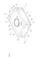
FIG. 1 is a perspective configuration diagram showing the exterior of a wipe dispenser (a first example) according to an embodiment of the present invention; -
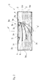
FIG. 2 is a cross-sectional diagram, taken along line A-A ofFIG. 1 ; -
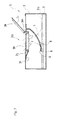
FIG. 3 is a cross-sectional diagram, taken along line A-A ofFIG. 1 , showing a state in which the wipes are consumed; -
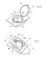
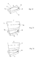
FIG. 4 is a perspective view showing an outlet member and a pressing member that configure the first example; -
FIG. 5 is a perspective view showing, from below, the outlet member and the pressing member that configure the first example; -
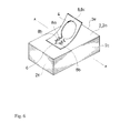
FIG. 6 is a perspective configuration diagram showing the pressing member and a stacked body that configure the first example; -
FIG. 7 is a perspective configuration diagram showing a partial modification of the configuration of the pressing member of the first example; -
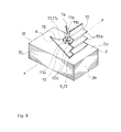
FIG. 8 is a perspective configuration diagram showing a pressing member and a stacked body that configure a wipe dispenser (a second example) according to an embodiment of the present invention; -
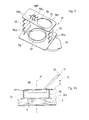
FIG. 9 is a perspective view showing, from below, an outlet member and a pressing member that configure a wipe dispenser (a third example) according to an embodiment of the present invention; -
FIG. 10 is a cross-sectional configuration diagram showing principal parts of the third example; -
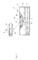
FIG. 11 is a cross-sectional configuration diagram of a wipe dispenser (a fourth example) according to an embodiment of the present invention; -
FIG. 12 is a perspective view showing, from below, an outlet member and a pressing member that configure the fourth example; -
FIG. 13 is a cross-sectional diagram of principal parts of the fourth example, showing a state before an opening member is removed; -
FIG. 14 is a cross-sectional diagram of principal parts of the fourth example, showing a state after the opening member is removed; -
FIG. 15 is a configuration diagram of the wipe dispenser that has a stacked body of wipes folded into an alphabet letter Z; -
FIG. 16 is a side configuration diagram showing a state in which the wipe stacked at the top of the stacked body shown inFIG. 15 is started to be pulled out; -
FIG. 17 is a side configuration diagram showing the step of pulling out the wipe stacked at the top of the stacked body shown inFIG. 15 , the wipe being pulled out more than it is as shown inFIG. 16 ; -
FIG. 18 is a side configuration diagram showing the step of pulling out the wipe stacked at the top of the stacked body shown inFIG. 15 , the wipe being pulled out more than it is as shown inFIG. 17 ; -
FIG. 19 shows a state in which the wipe following the wipe stacked at the top of the stacked body shown inFIG. 15 is lifted significantly when the wipe stacked at the top of the stacked body is pulled out; -
FIG. 20 is a side configuration diagram of a state in which the wipe stacked at the top of the stacked body shown inFIG. 15 is started to be pulled out, showing a state in which resistance is applied by the pressing member; -
FIG. 21 is a side configuration diagram of the step of pulling out the wipe stacked at the top of the stacked body, with the resistance applied by the pressing member, showing a state in which the wipe is pulled out more than it is shown inFIG. 20 ; -
FIG. 22 is a perspective configuration diagram showing a state in which the wipe that is stacked at the top of the stacked body is about to be pulled out in which the resistance of the pressing member is applied only to the right-hand side of an upper surface of the stacked body, the right-hand side, along with the left-hand side, having a virtual straight line therebetween which is perpendicular to the fold lines of the wipes of the stacked body and dividing the upper surface of the stacked body into two, the right-hand side and the left-hand side; -
FIG. 23 is a perspective configuration diagram showing a state following the state shown inFIG. 22 , in which the wipe stacked at the top of the stacked body is still being pulled; -
FIG. 24 is a perspective configuration diagram showing a state following the state shown inFIG. 23 , in which the wipe stacked at the top of the stacked body is completely pulled out; and -
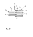
FIG. 25 is a side configuration diagram showing a state immediately before the wipe stacked at the top of the stacked body is completely pulled out, the wipe being folded into an alphabet letter W. - A typical embodiment of the present invention is now described hereinafter with reference to
FIGS. 1 to 25 . A wipe dispenser D according to this embodiment has a stackedbody 2 configured by sheet-like wipes 1, astorage body 3 that stores thestacked body 2 and has, at itsupper portion 3 b, adispenser opening 3 a from which thewipes 1 are pulled out, and apressing member 4 that is pressed against anupper surface 2 a of thestacked body 2 by biasing force. The present specification illustrates a typical form of using the wipe dispenser D in which thestorage body 3 is set up with the top wipe 1 of thestacked body 2 being positioned on the top side of the wipe dispenser D (horizontal use/seeFIG. 1 ). In this typical form of using the wipe dispenser D, the section on the top side is defined as theupper portion 3 b of thestorage body 3 and theupper surface 2 a of thestacked body 2, and the section on the bottom side is defined as alower portion 3 c of thestorage body 3 and alower surface 2 b of thestacked body 2. When using the wipe dispenser D vertically, theupper portion 3 b faces sideways. In the illustrated example, thestacked body 2 is in the shape of a hexahedron formed with the rectangular upper andlower surfaces front side surface 2 c” of the stacked body, the other one as “rear side surface 2 d” of the stacked body, one of the small sides of the hexahedron that is located to the right of thefront side surface 2 c as “right side surface 2 e,” and the other side located to the left of thefront side surface 2 c as “left side surface 2 f.” -
FIGS. 1 to 3 each show an example of thestorage body 3 made of soft packaging material such as a plastic film. Thestorage body 3 has theupper portion 3 b, thelower portion 3 c, fourside portions 3 d, configuring a hexahedral exterior. Although not shown, thestorage body 3 may be in the shape of a box made of plastic or the like. - The
dispenser opening 3 a from which thewipes 1 are pulled out is formed in theupper portion 3 b of thestorage body 3. In the illustrated example, thedispenser opening 3 a is configured with anopening 3 e provided at theupper portion 3 b of thestorage body 3 and anoutlet member 3 f attached on the inside of theupper portion 3 b of thestorage body 3. Although not shown, theoutlet member 3 f may be attached on the outside of theupper portion 3 b of thestorage body 3. - The
outlet member 3 f has a base 3 g larger than theopening 3 e and alid 3 i for closing adispenser port 3 h provided on thebase 3 g. In the illustrated example, the outer rim of the base 3 g of theoutlet member 3 f is fixed to the rim surrounding theopening 3 e of thestorage body 3 so that theopening 3 e of thestorage body 3 can be closed by theoutlet member 3 f. By opening thelid 3 i, the front edge of the top wipe 1 of thestacked body 2 in thestorage body 3 can be picked up through thedispenser port 3 h, and this wipe 1 can be pulled out of thestorage body 3. - In the illustrated example, the
base 3 g has, in an upper surface thereof, aperipheral wall 3 j surrounding thedispenser port 3 h, and thelid 3 i has, in a lower surface thereof, aperipheral wall 3 k that is fitted to theperipheral wall 3 j. Thedispenser port 3 h can be kept closed by thelid 3 i by fitting theperipheral wall 3 k to theperipheral wall 3 j. In the illustrated example, thelid 3 i and the base 3 g are integrated into a plastic molded article with an elasticallydeformable hinge portion 3 m therebetween. Thedispenser port 3 h is opened by turning thelid 3 i upward about thehinge portion 3 m with the amount of force enough to release theperipheral walls lid 3 i may be configured as a unit independent from the base 3 g that closes thedispenser port 3 h. - In the illustrated example, the
stacked body 2 is configured by stacking a plurality ofwipes 1 on top of each other, thewipes 1 being folded along two ormore fold lines 1 a. Therefore, thestacked body 2 is practically in the shape of a hexahedron. Thewipes 1 configuring thestacked body 2 are connected vertically so that when the first wipe 1 is pulled out, the second wipe 1 follows. In the illustrated example, thewipes 1 are stacked in such a manner that afront edge 1 b—the leading end—of the second wipe 1, which is pulled by the first wipe, is positioned above arear edge 1 c of the first wipe 1 (seeFIG. 15 ). - In the illustrated example, the
stacked body 2 has the rectangular upper andlower surfaces front side surface 2 c, therear side surface 2 d, theright side surface 2 e, and theleft side surface 2 f). (SeeFIG. 1 ) The fold lines 1 a of each wipe 1 are parallel to the long sides of theupper surface 2 a and thelower surface 2 b of thestacked body 2, and thefront side surface 2 c and therear side surface 2 d are shaped by thefold lines 1 a of the plurality of wipes 1 (seeFIG. 16 ). -
FIGS. 15 to 21 each show an example in which each of thewipes 1 is folded into an alphabet letter Z along the twofold lines 1 a (referred to as “Z-folded”, hereinafter). In thestacked body 2 configured by the Z-foldedwipes 1, thefold line 1 a in the vicinity of thefront edge 1 b of the second wipe 1 is located at either thefront side surface 2 c or therear side surface 2 d of thestacked body 2. -
FIG. 25 shows an example in which each of thewipes 1 is folded into an alphabet letter W along the threefold lines 1 a (referred to as “W-folded,” hereinafter). In thestacked body 2 configured with the W-foldedwipes 1, when thefold line 1 a in the vicinity of thefront edge 1 b of the second wipe 1 is located at thefront side surface 2 c of thestacked body 2, thefold line 1 a in the vicinity of thefront edge 1 b of the wipe 1 following the second wipe 1 is located at therear side surface 2 d of thestacked body 2. - The
wipes 1 are typically created by impregnating fabrics formed with paper, woven fabrics, non-woven fabrics or the like of synthetic fiber or natural fiber, with a chemical solution. Examples of the chemical solution include alcohols, water, and a mixture thereof in which fragrances, antibacterial agents, deodorants, surfactants, antiseptics, dyes, antifoaming agents, antioxidants, clarifying agents, solubilizers and the like can be blended, if necessary. - In the illustrated example, the pressing
member 4 is located between theoutlet member 3 f and theupper surface 2 a of thestacked body 2 and pressed against theupper surface 2 a of thestacked body 2 by biasing force. - In the wipe dispenser D according to this embodiment, first of all, the pressing
member 4 prevents thestacked body 2 configured by thewipes 1 from collapsing even when the wipe dispenser D is used vertically with thedispenser opening 3 a facing sideways. Therefore, the wipe dispenser D can be used vertically without any inconvenience. Second of all, the pressingmember 4 can prevent thestacked body 2 configured by thewipes 1 from becoming untidy in thestorage body 3. Thirdly, the pressingmember 4 can prevent as much as possible the shape-retaining ability of thestorage body 3 from being affected by the consumption of thewipes 1. - In the illustrated example, the pressing
member 4 is supported by theoutlet member 3 f. Thepressing member 4 may be supported by theoutlet member 3 f at one area or two or more areas. - In the first example shown in
FIGS. 1 to 6 , the pressingmember 4 is in a shape of a rectangular plate, the lower surface of which comes into abutment with theupper surface 2 a of thestacked body 2. Thewipes 1 configuring thestacked body 2 are each folded into a rectangle, in which thefold lines 1 a extend in the horizontal direction as shown inFIG. 2 . Thepressing member 4 has its width direction aligned perpendicular to thefold lines 1 a of thewipes 1 and has one end serving as apressing portion 6 abutting the upper surface of the stacked body and the other end connected to theoutlet member 3 f having thedispenser port 3 h by a connectingportion 7. Between thedispenser port 3 h and one of the sides of the base 3 g of theoutlet member 3 f, the connectingportion 7 protrudes downward from the lower surface of the base 3 g that faces thestacked body 2, and is in the shape of a rib extending in a direction perpendicular to thefold lines 1 a of thewipes 1. The other end of thepressing member 4 is integrated with the protruding end of the connectingportion 7. In the first example, the pressingmember 4 is integrated with theoutlet member 3 f into a plastic molded article. Thepressing member 4 is located between theoutlet member 3 f and theupper surface 2 a of thestacked body 2 while being elastically deformable so as to reduce the distance between thepressing portion 6 and the base 3 g. Thepressing member 4 elastically returns to increase the distance between thefree end 6 and theoutlet member 3 f as the number ofwipes 1 consumed increases. In the first example, the position shown by anumeral 4′ inFIG. 2 represents the state obtained before thepressing member 4 is elastically deformed. Also in the first example, the pressingmember 4 is bent, in which the lower surface thereof is bent outward. - In this embodiment, the pressing
member 4 ensures that the resistance that is generated when thewipes 1 are each pulled out of thedispenser opening 3 a is uneven between the left-hand side and the right-hand side of theupper surface 2 a of thestacked body 2 with a virtual straight line x therebetween, the virtual straight line being perpendicular to thefold lines 1 a of the wipes 1 (seeFIGS. 1 , 6, 7 and 8). - As described above, when the first wipe 1 of the
stacked body 2 is pulled out, the second wipe 1 follows. Without thepressing member 4, thefront edge 1 b of the second wipe 1 is lifted significantly (FIG. 19 ). - However, with the presence of the
pressing member 4, the resistance of thepressing member 4 acts on thefront edge 1 b of the second wipe 1. Therefore, therear edge 1 c of the first wipe 1 can easily separated from thefront edge 1 b of the second wipe 1, preventing thefront edge 1 b of the second wipe 1 from being lifted excessively (FIG. 21 ). - The resistance of the
pressing member 4 is ensured to be uneven between the left-hand side and the right-hand side with the virtual straight line x therebetween. Therefore, starting from the side where the resistance acts more, the separation between the first wipe 1 and the second wipe 1 begins, and thesewipes 1 continue to separate from each other in the remaining section. In other words, the wipe dispenser D of this embodiment can smoothly separate the first wipe 1 from the second wipe 1 (FIGS. 22 to 24 ). - In the first example, the
pressing portion 6 of thepressing member 4 is in abutment with theupper surface 2 a of thestacked body 2 at the left-hand side with respect to the virtual straight line x extending between the left-hand side and the right-hand side as shown inFIG. 1 (seeFIG. 2 . InFIGS. 2 and 10 , the virtual vertical plane having this virtual straight line x is denoted by “x′”). In other words, in the first example, the resistance of thepressing member 4 acts only on one of the sides of theupper surface 2 a of thestacked body 2 having the virtual straight line x therebetween. - Moreover, an additional
resistance application portion 8 that generates frictional force when thewipes 1 are pulled out is formed in thepressing member 4. In other words, thewipes 1 are pulled out of thestorage body 3 through this additionalresistance application portion 8 and thedispenser port 3 h. - The additional
resistance application portion 8 is configured with alarge resistance portion 8 a and a small resistance portion 8 c that apply frictional force in the passage of thewipes 1, in which the frictional force of thelarge resistance portion 8 a is greater than that of the small resistance portion 8 c. In addition to this, in the first example, thelarge resistance portion 8 a is located on the side where resistance induced by the biasing force is present, with the side having the virtual straight line x therebetween. - In the first example, the small resistance portion 8 c is practically configured by a circular hole that is big enough to allow each of the
wipes 1 to be picked up. Thelarge resistance portion 8 a, on the other hand, is in the shape of a split groove that has its groove end communicated with the small resistance portion 8 c and extends toward thepressing portion 6 of thepressing member 4. Thelarge resistance portion 8 a has front and rear groove edges along its extending direction and a plurality ofsawtooth edges 8 b that are arranged in the horizontal direction with spaces therebetween. - Therefore, in the first example, each of the
wipes 1 passing through the additionalresistance application portion 8 can be applied with large frictional force by thesawtooth edges 8 b of thelarge resistance portion 8 a at thepressing portion 6 side of thepressing member 4. With this mechanism, therefore, the first wipe 1 and the second wipe 1 can reliably be separated from each other. In addition, on the other side away from thepressing portion 6 of thepressing member 4, the small resistance portion 8 c allows the second wipe 1 to be lifted up moderately. -
FIG. 7 shows a partial modification of the first example, in which the lower surface of thepressing member 4 at thepressing portion 6 side is bent inward. - In the second example shown in
FIG. 8 , the pressingmember 4 has one end serving as a pressing portion 9 that comes into abutment with the upper surface of thestacked body 2, and is supported by theoutlet member 3 f with thedispenser port 3 h of the wipe 1 at the pressing portion 9 side via amomentum maintaining member 10. An additional resistance application portion 11 is disposed between the pressing portion 9 and the other end of thepressing member 4. In the second example, the pressingmember 4 has a right side 12 parallel to the virtual straight line x, front andrear sides left side 15, and is configured by a plate in which theleft side 15 is in the shape of a semicircular arc extending along a virtual arc, not shown. In the second example, themomentum maintaining member 10 is in the shape of a strip in which its upper end is integrated with the base 3 g of theoutlet member 3 f and its lower end integrated with the right side 12 of thepressing member 4. Themomentum maintaining member 10 has a plurality offold lines 10 a that are adjacent to one another extending along the width direction and that are formed at certain intervals in the vertical direction. With themomentum maintaining member 10 bent elastically along the plurality offold lines 10 a, the right side of thepressing member 4 is brought into abutment with theupper surface 2 a of thestacked body 2 at the right-hand side with respect to the virtual straight line x extending between the left-hand side and the right-hand side. In this state, the pressingmember 4 is placed in thestorage body 3 at a tilt, with the right side 12 being at the lowest position and theleft side 15 being at the top position. In other words, in the second example, the right side 12 of thepressing member 4 functions as the pressing portion 9. In the second example, a groove end that is connected to theleft side 15 is formed in thepressing member 4. This forms a split groove extending toward the pressing portion 9. This split groove has front and rear groove edges along its extending direction in which a plurality ofsawtooth edges 11 b are arranged in the horizontal direction) with spaces therebetween. In the second example, thewipes 1 can be pulled out through the split groove of thepressing member 4 and theleft side 15. In the second example, each of thewipes 1 passing through the split groove can be applied with large frictional force by thesawtooth edges 11 b at the pressing portion 9 side of thepressing member 4. In other words, in the second example, the split groove functions as alarge resistance portion 11 a and theleft side 15 of thepressing member 4 as a small resistance portion 11 c. - In the third example shown in
FIGS. 9 and 10 , the pressingmember 4 is supported by theoutlet member 3 f with thedispenser port 3 h of the wipe 1 viamomentum maintaining members 16 on both the left-hand side and the right-hand side having the virtual straight line x therebetween. In addition, the biasing force of themomentum maintaining member 16 on the left-hand side is different from the biasing force of themomentum maintaining member 16 on the right-hand side. In the third example, the pressingmember 4 is in a shape of a rectangular plate, the entire lower surface of which comes into abutment with theupper surface 2 a of thestacked body 2. Thepressing member 4 is connected to the base 3 g of theoutlet member 3 f via themomentum maintaining members 16 on the right-hand side and the left-hand side with thedispenser port 3 h therebetween. The left and rightmomentum maintaining members 16 each is in the shape of a strip in which the upper end thereof is integrated with the base 3 g and the lower end thereof integrated with the upper surface of thepressing member 4. Each of themomentum maintaining members 16 has a plurality offold lines 16 a which are adjacent to one another extending along the width direction of eachmomentum maintaining member 16 and which are disposed in the vertical direction with spaces therebetween. Thepressing member 4 has its lower surface in abutment with theupper surface 2 a of thestacked body 2 when elastically bent along the plurality offold lines 16 a. In the third example, the width of the right-sidemomentum maintaining member 16 is smaller than that of the left-sidemomentum maintaining member 16. Thus, the biasing force of the right-sidemomentum maintaining member 16 is smaller than that of the left-sidemomentum maintaining member 16. In the third example, therefore, the resistance of thepressing member 4 acts on both sides having the virtual straight line x therebetween but prevents the biasing force on one of the sides having the virtual straight line x therebetween from becoming equivalent to the biasing force on the other side. In the third example, the pressingmember 4 has apassage hole 17 for thewipes 1 that is elongated in the horizontal direction. The rim of thepassage hole 17 on the right-hand side with respect to substantially the middle of thepressing member 4 in its lengthwise direction is in the form of an arc of a virtual ellipse. On the left-hand side, on the other hand, the front and rear rims of thepassage hole 17 configure a plurality ofsawtooth edges 18 a that protrude inward and are arranged in the horizontal direction with spaces therebetween. In the third example, therefore, each of thewipes 1 is applied with resistance by thesawtooth edges 18 a on the left-hand side of thepassage hole 17 but does not receive such resistance on the right-hand side of thepassage hole 17. In other words, in the third example, the right-hand side of thepassage hole 17 of thepressing member 4 functions as a small resistance portion 18 c of an additionalresistance application portion 18, and the left-hand side of thepassage hole 17 functions as alarge resistance portion 18 a of the additionalresistance application portion 18. Thelarge resistance portion 18 a is located on the side where the biasing force-induced resistance is large, with the virtual straight line x between the right-hand side and the left-hand side. - In the fourth example shown in
FIGS. 11 to 14 , the wipe 1 dispenser D has a retainingmember 24 for keeping thepressing member 4 pulled in a direction against the biasing force. This retainingmember 24 is capable of releasing the pressing from this direction. The fourth example is added with the retainingmember 24 of the first example. -
FIG. 11 is a cross-sectional diagram taken along line AA ofFIG. 1 , showing a state before the wipe 1 dispenser D is used. When the wipe 1 dispenser D is not used (i.e., prior to the use of the wipe dispenser D), thedispenser port 3 h is completely sealed by an openingmember 25 provided below thelid 3 i, in order to prevent thestacked body 2 from completely drying out in thestorage body 3. The sealed state of thedispenser port 3 h is cancelled by removing the openingmember 25 from thedispenser port 3 h to the outside. - The opening
member 25 is integrated with theoutlet member 3 f. Afragile portion 26 having a V-shaped cross section is formed over the entire circumference of the outer periphery of the openingmember 25. A pull-top ring 27 that can be pulled outward by a fingertip is integrated with the openingmember 25. - In the unused state of the wipe 1 dispenser D in which the opening
member 25 is not yet removed from thedispenser port 3 h, thedispenser port 3 h is sealed with the openingmember 25. When the pull-top ring 27 is pulled outward, thefragile portion 26 collapses by shear failure and the openingmember 25 is removed to the outside, creating the state in which thewipes 1 can be pulled out of thestorage body 3 through thedispenser port 3 h of theoutlet member 3 f. - In the fourth example, the pair of retaining
members 24 protrudes from the rear surface of the opening member 25 (i.e., the surface that faces the inside of the storage body 3) toward the inside of thestorage body 3. The retainingmembers 24 keep thepressing member 4 pulled toward theoutlet member 3 f against the biasing force, so that thepressing member 4 is not pressed against thestacked body 2. - In the illustrated example, each of the retaining
members 24 is in the shape of a thin rod protruding from the rear surface side of the openingmember 25 and is connected to the openingmember 25, as shown inFIG. 12 and the like showing the back of thepressing member 4. Specifically, the retainingmembers 24 of this example are integrated with the openingmember 25. Also, in this example, these two retainingmembers 24 are formed at the front and back, in which an engagingportion 24 a that removably comes into engagement with the rear surface of the rim of thepressing member 4 in the lengthwise direction is formed at a tip of each retainingmember 24. Each of the engagingportions 24 a is in the shape of a hook in the illustrated example, but may be in any shape. In the illustrated example, the engagement between thepressing member 4 and the engagingportions 24 a is released by elastic deformation of the retainingmembers 24, by moving the retainingmember 24 to the outside by a certain distance. - As shown in
FIG. 13 , in the unused state in which the openingmember 25 is not yet removed, the engaging portions are in engagement with the rim of thepressing member 4 along the lengthwise direction, and keep thepressing member 4 pulled toward the vicinity of the rear surface of theoutlet member 3 f against the biasing force that tries to rotate thepressing member 4. - Such a configuration in which the
pressing member 4 of the wipe 1 dispenser D kept pulled toward the vicinity of the rear surface of theoutlet member 3 f enables smooth execution of the work processes in the process of manufacturing the wipe 1 dispenser D. In other words, such a configuration can reduce the possibility that thepressing member 4 might carelessly project toward the inside of thestorage body 3 during the work processes performed after thepressing member 4 is kept pulled toward the vicinity of the rear surface of theoutlet member 3 f. Therefore, the step of fixing thestorage body 3 and theoutlet member 3 f to each other, the step of packing thestacked body 2 in thestorage body 3 to which theoutlet member 3 f is fixed, and various other steps can be executed smoothly and easily using an automatic manufacturing machine. - As shown in
FIG. 14 , by removing the openingmember 25 to the outside in the beginning of the use of the wipe 1 dispenser D, the engagement between thepressing member 4 and the engagingportions 24 a of the retainingmembers 24 integrated with the openingmember 25 is released. Consequently, the pressingmember 4 is turned toward the inside of thestorage body 3 by the biasing force, as shown by the arrow F inFIG. 14 . As a result, when the wipe 1 dispenser D is being used, the pressingmember 4 is pressed against theupper surface 2 a of thestacked body 2. - Although not shown, the retaining
members 24 can each be configured with an adhesive for adhering the rear surface of the openingmember 25 to thepressing member 4. In such a case, the openingmember 25 and thepressing member 4 are formed into the shapes that enable the adhesion with the adhesive (e.g., in the form of sheets, etc.). In the unused state of the wipe 1 dispenser D of this configuration in which thedispenser port 3 h is sealed with the openingmember 25, the rear surface of the openingmember 25 and thepressing member 4 are adhered to each other, and thepressing member 4 is kept pulled toward the vicinity of the rear surface of theoutlet member 3 f. Then, once the openingmember 25 is removed from thedispenser port 3 h, the adhesion between the openingmember 25 and thepressing member 4 is released, pressing thepressing member 4 against thestacked body 2. - The present invention is not limited to the foregoing examples and encompasses all the aspects included in the concept of the present invention described in the claims.
Claims (7)
1. A wipe dispenser, comprising:
a stacked body configured by stacking sheet-like folded wipes;
a storage body for storing the stacked body and having, at an upper portion, a dispenser opening from which the wipes are pulled out; and
a pressing member that is pressed against an upper surface of the stacked body by biasing force, wherein
the pressing member ensures that resistance generated when pulling the wipes through the dispenser opening is uneven between a left-hand side and a right-hand side of the upper surface of the stacked body, which is divided by a virtual straight line therebetween that is perpendicular to a fold line of each of the wipes.
2. The wipe dispenser according to claim 1 , wherein the pressing member has an additional resistance application portion that acts on the wipes being pulled.
3. The wipe dispenser according to claim 2 , wherein
the additional resistance application portion is formed of a large resistance portion and a small resistance portion that each generate frictional force in the passage of the wipes, the frictional force of the large resistance portion being greater than that of the small resistance portion, and
the large resistance portion is located, across the virtual strait line, on the side where resistance induced by the biasing force exists or on the side where the resistance is large.
4. The wipe dispenser according to claim 3 , wherein the pressing member has one end serving as a pressing portion that comes into abutment with the upper surface of the stacked body, and has the other end supported by an outlet member.
5. The wipe dispenser according to claim 3 , wherein the pressing member has one end serving as a pressing portion that comes into abutment with the upper surface of the stacked body, and is supported on the side of the pressing portion by the outlet member via a momentum maintaining member, and the additional resistance application portion is provided between the pressing portion and the other end of the pressing member.
6. The wipe dispenser according to claim 3 , wherein the pressing member is supported by the outlet member via momentum maintaining members disposed on the left-hand side and the right-hand side with the virtual straight line therebetween, and biasing force of the left-side momentum maintaining member is different from that of the right-side momentum maintaining member.
7. The wipe dispenser according to claim 1 , further comprising a retaining member for keeping the pressing member in the state where the pressing member is pulled in a direction against the biasing force, the retaining member being capable of releasing the pressing member from this direction.
Applications Claiming Priority (5)
| Application Number | Priority Date | Filing Date | Title |
|---|---|---|---|
| PCT/JP2013/001700 WO2014141320A1 (en) | 2013-03-14 | 2013-03-14 | Wet tissue packaging body |
| JPPCT/JP2013/001700 | 2013-03-14 | ||
| PCT/JP2013/067740 WO2014141494A1 (en) | 2013-03-14 | 2013-06-21 | Wipe dispenser |
| JPPCT/JP2013/067740 | 2013-06-21 | ||
| PCT/JP2014/056249 WO2014142091A1 (en) | 2013-03-14 | 2014-03-11 | Wipe dispenser |
Publications (1)
| Publication Number | Publication Date |
|---|---|
| US20160000278A1 true US20160000278A1 (en) | 2016-01-07 |
Family
ID=51536027
Family Applications (3)
| Application Number | Title | Priority Date | Filing Date |
|---|---|---|---|
| US14/761,225 Abandoned US20150368026A1 (en) | 2013-03-14 | 2013-03-14 | Wet tissue package |
| US14/776,377 Abandoned US20160022098A1 (en) | 2013-03-14 | 2013-06-21 | Wipe dispenser |
| US14/771,958 Abandoned US20160000278A1 (en) | 2013-03-14 | 2014-03-11 | Wipe dispenser |
Family Applications Before (2)
| Application Number | Title | Priority Date | Filing Date |
|---|---|---|---|
| US14/761,225 Abandoned US20150368026A1 (en) | 2013-03-14 | 2013-03-14 | Wet tissue package |
| US14/776,377 Abandoned US20160022098A1 (en) | 2013-03-14 | 2013-06-21 | Wipe dispenser |
Country Status (9)
| Country | Link |
|---|---|
| US (3) | US20150368026A1 (en) |
| EP (3) | EP2974979A4 (en) |
| JP (3) | JP6277177B2 (en) |
| KR (1) | KR20150126339A (en) |
| CN (2) | CN105189307B (en) |
| BR (1) | BR112015020803A2 (en) |
| CA (3) | CA2899397A1 (en) |
| MX (3) | MX2015010303A (en) |
| WO (3) | WO2014141320A1 (en) |
Cited By (4)
| Publication number | Priority date | Publication date | Assignee | Title |
|---|---|---|---|---|
| US20200046177A1 (en) * | 2018-08-13 | 2020-02-13 | The Procter & Gamble Counsel | Package of disposable wipes |
| US10729288B2 (en) * | 2019-01-04 | 2020-08-04 | Julie Moore | Universal cover for hygiene cloth dispensers |
| US20220297923A1 (en) * | 2021-03-18 | 2022-09-22 | PaaNeeCo, Inc. | Wipe container allowing cleaning wipe to be withdrawn without contact and sealing method thereof |
| US20220332474A1 (en) * | 2021-04-15 | 2022-10-20 | Professional Disposables International, Inc. | Lid for container |
Families Citing this family (14)
| Publication number | Priority date | Publication date | Assignee | Title |
|---|---|---|---|---|
| US20160106273A1 (en) * | 2013-06-19 | 2016-04-21 | Kikuo Yamada | Wet wipe packaging body |
| USD809318S1 (en) | 2016-06-06 | 2018-02-06 | Mathew H. Hammons | Mountable holder for a box dispenser of safety gloves, having auxiliary dispensing/metering provisions |
| US10278552B2 (en) | 2016-12-08 | 2019-05-07 | The Clorox Company | Disinfecting wipes flex pack closure |
| DE102017111233A1 (en) | 2017-05-23 | 2018-11-29 | Bode Chemie Gmbh | Holding system for providing a package provided with cleaning or disinfection wipes or disposable gloves |
| JP7013690B2 (en) * | 2017-06-23 | 2022-02-01 | 凸版印刷株式会社 | Liquid injection type sheet container |
| US10196198B1 (en) * | 2017-08-03 | 2019-02-05 | Kleen Test Products Corporation | Stacked article retrieval apparatus |
| USD837661S1 (en) | 2017-11-09 | 2019-01-08 | The Clorox Company | Wipes dispenser opening |
| US10827885B2 (en) | 2018-09-24 | 2020-11-10 | Sameer SAID | Angled flushable moist wipe dispenser |
| JP7149148B2 (en) | 2018-09-28 | 2022-10-06 | 大王製紙株式会社 | Sheet dispenser and attachment for sheet dispenser |
| KR102155774B1 (en) * | 2018-11-30 | 2020-09-15 | 주식회사 96퍼센트 | Withdrawable mask pack |
| JP6554741B1 (en) * | 2019-02-22 | 2019-08-07 | 進一 塚本 | Package |
| JP7464409B2 (en) | 2020-03-03 | 2024-04-09 | 大王製紙株式会社 | Wet wipes storage container |
| CN111991250B (en) * | 2020-06-22 | 2023-04-18 | 浙江新远实业有限公司 | Refreshing mosquito-repelling wet tissue finishing liquid and preparation method thereof |
| JP7021310B1 (en) | 2020-08-28 | 2022-02-16 | ダグラス シンクレア グラント | Wiping sheet take-out member and wiping sheet storage container |
Citations (7)
| Publication number | Priority date | Publication date | Assignee | Title |
|---|---|---|---|---|
| US1603714A (en) * | 1922-10-03 | 1926-10-19 | Golco Sanitary System Inc | Container for paper napkins and the like |
| US1773652A (en) * | 1929-05-07 | 1930-08-19 | Fred C Traver | Container |
| US3473694A (en) * | 1967-08-25 | 1969-10-21 | Int Paper Canada | Carton |
| US3982659A (en) * | 1975-12-24 | 1976-09-28 | Scott Paper Company | Bulk package for substantially wet sheets and dispensing device therefor |
| US6499626B1 (en) * | 2000-11-22 | 2002-12-31 | Nice-Pak Products, Inc. | Dispenser for articles |
| US20030080018A1 (en) * | 2001-10-30 | 2003-05-01 | Nally William T. | Cleansing wipe dispenser |
| US20050236416A1 (en) * | 2002-05-28 | 2005-10-27 | Georgia-Pacific Corporation | Refillable flexible sheet dispenser |
Family Cites Families (38)
| Publication number | Priority date | Publication date | Assignee | Title |
|---|---|---|---|---|
| US3207360A (en) * | 1961-07-28 | 1965-09-21 | Scott Paper Co | Sheet packaging arrangements |
| US3121510A (en) * | 1961-12-28 | 1964-02-18 | American Can Co | Sheet dispenser |
| US3197062A (en) * | 1962-09-27 | 1965-07-27 | Kimberly Clark Co | Expandable tissue dispensing package |
| US3265242A (en) * | 1964-08-06 | 1966-08-09 | Georgia Pacific Corp | Tissue dispenser with a movable dispensing sheet |
| GB1085560A (en) * | 1965-05-15 | 1967-10-04 | Int Paper Canada | Carton |
| US3606082A (en) * | 1969-06-04 | 1971-09-20 | American Can Co | Dispensing control member for interfolded tissues |
| JPS5727360Y2 (en) * | 1978-07-29 | 1982-06-14 | ||
| JPS5549612U (en) * | 1978-09-28 | 1980-04-01 | ||
| JPS59193180U (en) * | 1983-06-09 | 1984-12-21 | 清藤 三津郎 | Teitshu Paper Boxes |
| US4580695A (en) * | 1984-09-27 | 1986-04-08 | Lum Thomas Y J | Porta towel |
| JPH0515676Y2 (en) | 1987-11-17 | 1993-04-23 | ||
| JPH01178791U (en) * | 1988-06-04 | 1989-12-21 | ||
| JPH0824636B2 (en) * | 1993-04-08 | 1996-03-13 | ジェクス株式会社 | Packaging bag for skin cleansing products |
| CA2102163A1 (en) * | 1993-11-01 | 1995-05-02 | Charles A. Annand | Top opening facial tissue container |
| JP3416360B2 (en) * | 1995-11-08 | 2003-06-16 | ユニ・チャーム株式会社 | Wet napkin storage container |
| US5810200A (en) * | 1996-08-09 | 1998-09-22 | The Procter & Gamble Company | Pop-up tissue package |
| JP3050201U (en) * | 1997-12-26 | 1998-06-30 | 千代恵 山田 | Container having lid with pressing part |
| US5992683A (en) * | 1998-08-31 | 1999-11-30 | Kimberly-Clark Worldwide, Inc. | Clip lift for sheet dispensing system |
| CN1300537C (en) * | 1999-09-14 | 2007-02-14 | 宫比株式会社 | Wet tissue warmer |
| US6550636B2 (en) * | 2001-01-15 | 2003-04-22 | Menasha Corporation | Sheet dispenser |
| JP2003012053A (en) * | 2001-06-29 | 2003-01-15 | Kanebo Ltd | Soft package |
| US6688488B2 (en) * | 2002-03-12 | 2004-02-10 | 3M Innovative Properties Company | Blister spring for pop-up sheet material dispenser |
| JP3995975B2 (en) * | 2002-04-24 | 2007-10-24 | 株式会社ニチエイ | Portable sheet material packaging |
| JP2004196303A (en) | 2002-12-16 | 2004-07-15 | Meisei Sansho Kk | Wet tissue package |
| JP4837881B2 (en) * | 2003-01-14 | 2011-12-14 | ユニ・チャーム株式会社 | Container with lid |
| US7273156B2 (en) * | 2004-06-02 | 2007-09-25 | Kimberly-Clark Worldwide, Inc. | Adjustable sheet dispenser |
| JP4791111B2 (en) * | 2004-09-22 | 2011-10-12 | ユニ・チャーム株式会社 | Tissue feeding container |
| WO2006107811A2 (en) * | 2005-04-01 | 2006-10-12 | Ranpak Corp. | Manual dunnage converting system and method |
| US7556175B2 (en) * | 2006-02-28 | 2009-07-07 | Joseph S. Kanfer | Towelette dispenser |
| CN201046806Y (en) * | 2007-05-14 | 2008-04-16 | 卢同升 | Plastic receptacle for putting wet tissue |
| JP2010173649A (en) | 2009-01-27 | 2010-08-12 | Kenji Fujimaki | Wet tissue package |
| JP5275870B2 (en) * | 2009-03-26 | 2013-08-28 | 大王製紙株式会社 | Household thin paper storage container |
| RU2488341C1 (en) * | 2009-04-17 | 2013-07-27 | Ска Хайджин Продактс Аб | Dispenser for distribution of sanitary and hygienic purpose paper and method for sanitary and hygienic purpose paper distribution |
| US8245876B2 (en) * | 2009-07-15 | 2012-08-21 | The Procter & Gamble Company | Wipes container |
| ES2386603T3 (en) * | 2009-12-18 | 2012-08-23 | The Procter & Gamble Company | Flexible container and reusable closure element |
| JP5912288B2 (en) | 2010-11-25 | 2016-04-27 | 山田 菊夫 | Wet tissue packaging |
| US8210393B1 (en) * | 2011-01-24 | 2012-07-03 | Prodius, LLC | Tissue dispensing device |
| JP3170526U (en) * | 2011-06-24 | 2011-09-22 | 有限会社美容室ゼロ | Paper storage body |
-
2013
- 2013-03-14 WO PCT/JP2013/001700 patent/WO2014141320A1/en active Application Filing
- 2013-03-14 EP EP13877489.8A patent/EP2974979A4/en not_active Withdrawn
- 2013-03-14 CN CN201380045069.XA patent/CN105189307B/en not_active Expired - Fee Related
- 2013-03-14 JP JP2015505076A patent/JP6277177B2/en not_active Expired - Fee Related
- 2013-03-14 KR KR1020157001125A patent/KR20150126339A/en not_active Application Discontinuation
- 2013-03-14 US US14/761,225 patent/US20150368026A1/en not_active Abandoned
- 2013-03-14 CA CA2899397A patent/CA2899397A1/en not_active Abandoned
- 2013-03-14 BR BR112015020803A patent/BR112015020803A2/en not_active IP Right Cessation
- 2013-03-14 MX MX2015010303A patent/MX2015010303A/en unknown
- 2013-06-21 EP EP13877536.6A patent/EP2974980A4/en not_active Withdrawn
- 2013-06-21 WO PCT/JP2013/067740 patent/WO2014141494A1/en active Application Filing
- 2013-06-21 CA CA2908687A patent/CA2908687A1/en not_active Abandoned
- 2013-06-21 MX MX2015012791A patent/MX2015012791A/en unknown
- 2013-06-21 JP JP2015505218A patent/JP6189931B2/en not_active Expired - Fee Related
- 2013-06-21 US US14/776,377 patent/US20160022098A1/en not_active Abandoned
-
2014
- 2014-03-11 US US14/771,958 patent/US20160000278A1/en not_active Abandoned
- 2014-03-11 EP EP14764847.1A patent/EP2974982A4/en not_active Withdrawn
- 2014-03-11 MX MX2015012498A patent/MX2015012498A/en unknown
- 2014-03-11 CN CN201480015240.7A patent/CN105050915A/en active Pending
- 2014-03-11 JP JP2015505477A patent/JPWO2014142091A1/en not_active Withdrawn
- 2014-03-11 CA CA2905287A patent/CA2905287A1/en not_active Abandoned
- 2014-03-11 WO PCT/JP2014/056249 patent/WO2014142091A1/en active Application Filing
Patent Citations (7)
| Publication number | Priority date | Publication date | Assignee | Title |
|---|---|---|---|---|
| US1603714A (en) * | 1922-10-03 | 1926-10-19 | Golco Sanitary System Inc | Container for paper napkins and the like |
| US1773652A (en) * | 1929-05-07 | 1930-08-19 | Fred C Traver | Container |
| US3473694A (en) * | 1967-08-25 | 1969-10-21 | Int Paper Canada | Carton |
| US3982659A (en) * | 1975-12-24 | 1976-09-28 | Scott Paper Company | Bulk package for substantially wet sheets and dispensing device therefor |
| US6499626B1 (en) * | 2000-11-22 | 2002-12-31 | Nice-Pak Products, Inc. | Dispenser for articles |
| US20030080018A1 (en) * | 2001-10-30 | 2003-05-01 | Nally William T. | Cleansing wipe dispenser |
| US20050236416A1 (en) * | 2002-05-28 | 2005-10-27 | Georgia-Pacific Corporation | Refillable flexible sheet dispenser |
Cited By (7)
| Publication number | Priority date | Publication date | Assignee | Title |
|---|---|---|---|---|
| US20200046177A1 (en) * | 2018-08-13 | 2020-02-13 | The Procter & Gamble Counsel | Package of disposable wipes |
| US10791887B2 (en) * | 2018-08-13 | 2020-10-06 | The Procter & Gamble Company | Package of disposable wipes |
| US10729288B2 (en) * | 2019-01-04 | 2020-08-04 | Julie Moore | Universal cover for hygiene cloth dispensers |
| US11246459B2 (en) | 2019-01-04 | 2022-02-15 | Julie Moore | Universal cover for hygiene cloth dispensers |
| US20220297923A1 (en) * | 2021-03-18 | 2022-09-22 | PaaNeeCo, Inc. | Wipe container allowing cleaning wipe to be withdrawn without contact and sealing method thereof |
| US11485569B2 (en) * | 2021-03-18 | 2022-11-01 | PaaNeeCo, Inc. | Wipe container allowing cleaning wipe to be withdrawn without contact and sealing method thereof |
| US20220332474A1 (en) * | 2021-04-15 | 2022-10-20 | Professional Disposables International, Inc. | Lid for container |
Also Published As
| Publication number | Publication date |
|---|---|
| EP2974982A1 (en) | 2016-01-20 |
| JPWO2014142091A1 (en) | 2017-02-16 |
| JP6277177B2 (en) | 2018-02-14 |
| MX2015012791A (en) | 2016-04-28 |
| CA2905287A1 (en) | 2014-09-18 |
| CA2908687A1 (en) | 2014-09-18 |
| CN105189307B (en) | 2017-07-04 |
| MX2015012498A (en) | 2016-01-12 |
| CN105050915A (en) | 2015-11-11 |
| EP2974979A4 (en) | 2016-12-14 |
| KR20150126339A (en) | 2015-11-11 |
| EP2974980A1 (en) | 2016-01-20 |
| EP2974979A1 (en) | 2016-01-20 |
| JP6189931B2 (en) | 2017-08-30 |
| BR112015020803A2 (en) | 2017-07-18 |
| WO2014142091A1 (en) | 2014-09-18 |
| US20160022098A1 (en) | 2016-01-28 |
| JPWO2014141320A1 (en) | 2017-02-16 |
| EP2974982A4 (en) | 2016-11-02 |
| US20150368026A1 (en) | 2015-12-24 |
| MX2015010303A (en) | 2016-03-16 |
| EP2974980A4 (en) | 2016-11-02 |
| CA2899397A1 (en) | 2014-09-18 |
| WO2014141494A1 (en) | 2014-09-18 |
| WO2014141320A1 (en) | 2014-09-18 |
| JPWO2014141494A1 (en) | 2017-02-16 |
| CN105189307A (en) | 2015-12-23 |
Similar Documents
| Publication | Publication Date | Title |
|---|---|---|
| US20160000278A1 (en) | Wipe dispenser | |
| US20150250364A1 (en) | Wipe container holder and wipe dispenser | |
| US6412634B1 (en) | Refillable towelette dispensing article | |
| WO2014203398A1 (en) | Wipe dispenser | |
| JP6174565B2 (en) | Wet tissue packaging | |
| EP3007988B1 (en) | Resealable and refillable wipes dispenser | |
| KR101769271B1 (en) | Pop-up type wet tissue cap capable of installing it to film pack for packaging wet tissue | |
| US20100078443A1 (en) | Wipes Canister Opening | |
| JP6822823B2 (en) | Lid mechanism, packaging and distribution container | |
| JP2018076109A5 (en) | ||
| US20140190983A1 (en) | Towelette Dispenser | |
| KR101280064B1 (en) | Tissue pack | |
| CN103260491A (en) | Dispensing system comprising holder and dispensing package | |
| US20090200331A1 (en) | Inner container of sheets to be dispensed | |
| JP6588713B2 (en) | Household thin paper storage container | |
| KR20160138463A (en) | Dispensing container having flexible dispensing partition | |
| JP5830962B2 (en) | Standing pouch | |
| JP2010247899A (en) | Household tissue storage container | |
| JP2017013854A (en) | Structure | |
| WO2014073117A1 (en) | Web package | |
| EP2557046A1 (en) | Packing case | |
| JP3124191B2 (en) | Wet tissue refill container | |
| KR20170017222A (en) | Pop-up type wet tissue cap capable of installing it to film pack for packaging wet tissue | |
| JP2020111335A (en) | Lid body of sheet-like article storing container and tip for sheet-like article distribution | |
| JP2015140215A (en) | Wipe storage container and wipe dispenser |
Legal Events
| Date | Code | Title | Description |
|---|---|---|---|
| STCB | Information on status: application discontinuation |
Free format text: ABANDONED -- FAILURE TO RESPOND TO AN OFFICE ACTION |