US20160143467A1 - Air Purging Lid - Google Patents
Air Purging Lid Download PDFInfo
- Publication number
- US20160143467A1 US20160143467A1 US15/012,766 US201615012766A US2016143467A1 US 20160143467 A1 US20160143467 A1 US 20160143467A1 US 201615012766 A US201615012766 A US 201615012766A US 2016143467 A1 US2016143467 A1 US 2016143467A1
- Authority
- US
- United States
- Prior art keywords
- lid
- edge
- container
- perforation
- tab
- Prior art date
- Legal status (The legal status is an assumption and is not a legal conclusion. Google has not performed a legal analysis and makes no representation as to the accuracy of the status listed.)
- Abandoned
Links
Images


Classifications
-
- A—HUMAN NECESSITIES
- A47—FURNITURE; DOMESTIC ARTICLES OR APPLIANCES; COFFEE MILLS; SPICE MILLS; SUCTION CLEANERS IN GENERAL
- A47G—HOUSEHOLD OR TABLE EQUIPMENT
- A47G21/00—Table-ware
- A47G21/06—Combined or separable sets of table-service utensils; Oyster knives with openers; Fish servers with means for removing bones
-
- A—HUMAN NECESSITIES
- A47—FURNITURE; DOMESTIC ARTICLES OR APPLIANCES; COFFEE MILLS; SPICE MILLS; SUCTION CLEANERS IN GENERAL
- A47G—HOUSEHOLD OR TABLE EQUIPMENT
- A47G19/00—Table service
- A47G19/22—Drinking vessels or saucers used for table service
- A47G19/2205—Drinking glasses or vessels
-
- B—PERFORMING OPERATIONS; TRANSPORTING
- B65—CONVEYING; PACKING; STORING; HANDLING THIN OR FILAMENTARY MATERIAL
- B65B—MACHINES, APPARATUS OR DEVICES FOR, OR METHODS OF, PACKAGING ARTICLES OR MATERIALS; UNPACKING
- B65B31/00—Packaging articles or materials under special atmospheric or gaseous conditions; Adding propellants to aerosol containers
-
- B—PERFORMING OPERATIONS; TRANSPORTING
- B65—CONVEYING; PACKING; STORING; HANDLING THIN OR FILAMENTARY MATERIAL
- B65B—MACHINES, APPARATUS OR DEVICES FOR, OR METHODS OF, PACKAGING ARTICLES OR MATERIALS; UNPACKING
- B65B7/00—Closing containers or receptacles after filling
- B65B7/16—Closing semi-rigid or rigid containers or receptacles not deformed by, or not taking-up shape of, contents, e.g. boxes or cartons
- B65B7/28—Closing semi-rigid or rigid containers or receptacles not deformed by, or not taking-up shape of, contents, e.g. boxes or cartons by applying separate preformed closures, e.g. lids, covers
- B65B7/2842—Securing closures on containers
-
- B—PERFORMING OPERATIONS; TRANSPORTING
- B65—CONVEYING; PACKING; STORING; HANDLING THIN OR FILAMENTARY MATERIAL
- B65D—CONTAINERS FOR STORAGE OR TRANSPORT OF ARTICLES OR MATERIALS, e.g. BAGS, BARRELS, BOTTLES, BOXES, CANS, CARTONS, CRATES, DRUMS, JARS, TANKS, HOPPERS, FORWARDING CONTAINERS; ACCESSORIES, CLOSURES, OR FITTINGS THEREFOR; PACKAGING ELEMENTS; PACKAGES
- B65D25/00—Details of other kinds or types of rigid or semi-rigid containers
- B65D25/02—Internal fittings
- B65D25/04—Partitions
-
- B—PERFORMING OPERATIONS; TRANSPORTING
- B65—CONVEYING; PACKING; STORING; HANDLING THIN OR FILAMENTARY MATERIAL
- B65D—CONTAINERS FOR STORAGE OR TRANSPORT OF ARTICLES OR MATERIALS, e.g. BAGS, BARRELS, BOTTLES, BOXES, CANS, CARTONS, CRATES, DRUMS, JARS, TANKS, HOPPERS, FORWARDING CONTAINERS; ACCESSORIES, CLOSURES, OR FITTINGS THEREFOR; PACKAGING ELEMENTS; PACKAGES
- B65D7/00—Containers having bodies formed by interconnecting or uniting two or more rigid, or substantially rigid, components made wholly or mainly of metal
- B65D7/02—Containers having bodies formed by interconnecting or uniting two or more rigid, or substantially rigid, components made wholly or mainly of metal characterised by shape
- B65D7/04—Containers having bodies formed by interconnecting or uniting two or more rigid, or substantially rigid, components made wholly or mainly of metal characterised by shape of curved cross-section, e.g. cans of circular or elliptical cross-section
-
- B—PERFORMING OPERATIONS; TRANSPORTING
- B65—CONVEYING; PACKING; STORING; HANDLING THIN OR FILAMENTARY MATERIAL
- B65D—CONTAINERS FOR STORAGE OR TRANSPORT OF ARTICLES OR MATERIALS, e.g. BAGS, BARRELS, BOTTLES, BOXES, CANS, CARTONS, CRATES, DRUMS, JARS, TANKS, HOPPERS, FORWARDING CONTAINERS; ACCESSORIES, CLOSURES, OR FITTINGS THEREFOR; PACKAGING ELEMENTS; PACKAGES
- B65D7/00—Containers having bodies formed by interconnecting or uniting two or more rigid, or substantially rigid, components made wholly or mainly of metal
- B65D7/12—Containers having bodies formed by interconnecting or uniting two or more rigid, or substantially rigid, components made wholly or mainly of metal characterised by wall construction or by connections between walls
- B65D7/24—Containers having bodies formed by interconnecting or uniting two or more rigid, or substantially rigid, components made wholly or mainly of metal characterised by wall construction or by connections between walls collapsible, e.g. with all parts detachable
- B65D7/28—Containers having bodies formed by interconnecting or uniting two or more rigid, or substantially rigid, components made wholly or mainly of metal characterised by wall construction or by connections between walls collapsible, e.g. with all parts detachable with some parts detachable and other parts hinged together
-
- B—PERFORMING OPERATIONS; TRANSPORTING
- B65—CONVEYING; PACKING; STORING; HANDLING THIN OR FILAMENTARY MATERIAL
- B65D—CONTAINERS FOR STORAGE OR TRANSPORT OF ARTICLES OR MATERIALS, e.g. BAGS, BARRELS, BOTTLES, BOXES, CANS, CARTONS, CRATES, DRUMS, JARS, TANKS, HOPPERS, FORWARDING CONTAINERS; ACCESSORIES, CLOSURES, OR FITTINGS THEREFOR; PACKAGING ELEMENTS; PACKAGES
- B65D77/00—Packages formed by enclosing articles or materials in preformed containers, e.g. boxes, cartons, sacks or bags
- B65D77/04—Articles or materials enclosed in two or more containers disposed one within another
- B65D77/048—Articles or materials enclosed in two or more containers disposed one within another the inner and outer containers being rigid and the outer container being of curved cross-section, e.g. cylindrical
- B65D77/0486—Articles or materials enclosed in two or more containers disposed one within another the inner and outer containers being rigid and the outer container being of curved cross-section, e.g. cylindrical the inner container being coaxially disposed within the outer container
- B65D77/0493—Articles or materials enclosed in two or more containers disposed one within another the inner and outer containers being rigid and the outer container being of curved cross-section, e.g. cylindrical the inner container being coaxially disposed within the outer container and retained at a distance of the inner side-wall of the outer container, e.g. within a bottle neck
-
- B—PERFORMING OPERATIONS; TRANSPORTING
- B65—CONVEYING; PACKING; STORING; HANDLING THIN OR FILAMENTARY MATERIAL
- B65D—CONTAINERS FOR STORAGE OR TRANSPORT OF ARTICLES OR MATERIALS, e.g. BAGS, BARRELS, BOTTLES, BOXES, CANS, CARTONS, CRATES, DRUMS, JARS, TANKS, HOPPERS, FORWARDING CONTAINERS; ACCESSORIES, CLOSURES, OR FITTINGS THEREFOR; PACKAGING ELEMENTS; PACKAGES
- B65D77/00—Packages formed by enclosing articles or materials in preformed containers, e.g. boxes, cartons, sacks or bags
- B65D77/10—Container closures formed after filling
- B65D77/20—Container closures formed after filling by applying separate lids or covers, i.e. flexible membrane or foil-like covers
- B65D77/2024—Container closures formed after filling by applying separate lids or covers, i.e. flexible membrane or foil-like covers the cover being welded or adhered to the container
- B65D77/2028—Means for opening the cover other than, or in addition to, a pull tab
- B65D77/2032—Means for opening the cover other than, or in addition to, a pull tab by peeling or tearing the cover from the container
-
- B—PERFORMING OPERATIONS; TRANSPORTING
- B65—CONVEYING; PACKING; STORING; HANDLING THIN OR FILAMENTARY MATERIAL
- B65D—CONTAINERS FOR STORAGE OR TRANSPORT OF ARTICLES OR MATERIALS, e.g. BAGS, BARRELS, BOTTLES, BOXES, CANS, CARTONS, CRATES, DRUMS, JARS, TANKS, HOPPERS, FORWARDING CONTAINERS; ACCESSORIES, CLOSURES, OR FITTINGS THEREFOR; PACKAGING ELEMENTS; PACKAGES
- B65D81/00—Containers, packaging elements, or packages, for contents presenting particular transport or storage problems, or adapted to be used for non-packaging purposes after removal of contents
- B65D81/18—Containers, packaging elements, or packages, for contents presenting particular transport or storage problems, or adapted to be used for non-packaging purposes after removal of contents providing specific environment for contents, e.g. temperature above or below ambient
- B65D81/20—Containers, packaging elements, or packages, for contents presenting particular transport or storage problems, or adapted to be used for non-packaging purposes after removal of contents providing specific environment for contents, e.g. temperature above or below ambient under vacuum or superatmospheric pressure, or in a special atmosphere, e.g. of inert gas
- B65D81/2069—Containers, packaging elements, or packages, for contents presenting particular transport or storage problems, or adapted to be used for non-packaging purposes after removal of contents providing specific environment for contents, e.g. temperature above or below ambient under vacuum or superatmospheric pressure, or in a special atmosphere, e.g. of inert gas in a special atmosphere
- B65D81/2076—Containers, packaging elements, or packages, for contents presenting particular transport or storage problems, or adapted to be used for non-packaging purposes after removal of contents providing specific environment for contents, e.g. temperature above or below ambient under vacuum or superatmospheric pressure, or in a special atmosphere, e.g. of inert gas in a special atmosphere in an at least partially rigid container
-
- B—PERFORMING OPERATIONS; TRANSPORTING
- B65—CONVEYING; PACKING; STORING; HANDLING THIN OR FILAMENTARY MATERIAL
- B65D—CONTAINERS FOR STORAGE OR TRANSPORT OF ARTICLES OR MATERIALS, e.g. BAGS, BARRELS, BOTTLES, BOXES, CANS, CARTONS, CRATES, DRUMS, JARS, TANKS, HOPPERS, FORWARDING CONTAINERS; ACCESSORIES, CLOSURES, OR FITTINGS THEREFOR; PACKAGING ELEMENTS; PACKAGES
- B65D81/00—Containers, packaging elements, or packages, for contents presenting particular transport or storage problems, or adapted to be used for non-packaging purposes after removal of contents
- B65D81/24—Adaptations for preventing deterioration or decay of contents; Applications to the container or packaging material of food preservatives, fungicides, pesticides or animal repellants
- B65D81/245—Internal membrane, floating cover or the like isolating the contents from the ambient atmosphere
-
- B—PERFORMING OPERATIONS; TRANSPORTING
- B65—CONVEYING; PACKING; STORING; HANDLING THIN OR FILAMENTARY MATERIAL
- B65D—CONTAINERS FOR STORAGE OR TRANSPORT OF ARTICLES OR MATERIALS, e.g. BAGS, BARRELS, BOTTLES, BOXES, CANS, CARTONS, CRATES, DRUMS, JARS, TANKS, HOPPERS, FORWARDING CONTAINERS; ACCESSORIES, CLOSURES, OR FITTINGS THEREFOR; PACKAGING ELEMENTS; PACKAGES
- B65D85/00—Containers, packaging elements or packages, specially adapted for particular articles or materials
- B65D85/70—Containers, packaging elements or packages, specially adapted for particular articles or materials for materials not otherwise provided for
- B65D85/72—Containers, packaging elements or packages, specially adapted for particular articles or materials for materials not otherwise provided for for edible or potable liquids, semiliquids, or plastic or pasty materials
Definitions
- the present invention relates in general to a container and lid system, and more particularly to a nest container and lid device and method for opening the same.
- Ready to drink packaging offers individual wine servings with a perfectly paired snack to enhance the wine's natural flavors and satisfy your appetite.
- the standard size shatterproof stemless wine glass is easily packed, unbreakable, and spill-proof.
- Ready to drink packaging is the perfect glass of wine, each and every time.
- the innovative lid is mechanically sealed. Once the lid is opened, the wine is at just the right level to swirl, taste, and allow the wine to breathe—without spilling a drop.
- Ready to drink packaging can be adapted to fit almost any type of glass. Easily adapted into a friendly shape for children, the ready to drink packaging can be filled with organic fruit juice or milk and paired with healthy snacks for moms on the go. All mom has to do is throw the drink in her bag and she has a drink and a snack in one. Ready to drink packaging is perfect for special occasions so children can have individual glasses of sparkling cider with a chocolate snack. It can be used as a party favor or personalized for a gift or promotional item. Ready to drink is easily stackable in either a refrigerator or ice chest and more special than a juice box.
- Ready to drink is just right when you want a single glass of wine. You can also mix and match, so if you want red and your friend wants white, you can have both, as each package can be customized in contents. Ready to drink safety material is the perfect container in places where glass containers are not allowed such as beaches, parks, etc.
- a lid is typically installed during a gas evacuation and/or displacement process. This is typically achieved by dispensing an inert gas into the space between the fluid and the lid as the lid is installed and/or by performing the lid installation operation within a vacuum chamber.
- the headspaces in wine is purged by use of an inert gas to effectively remove the oxygen to greatly increase the amount of protection.
- tall slender containers are preferred to short wider containers because fluids stored in taller slender containers have less exposed surface area to the entrapped atmospheric gases.
- the oxygen uptake depends on the surface area exposed to oxygen and the exposure time. The rate of oxidation increases as the exposed surface area increases. As the rate of oxidation increases the shelf life of the wine decreases before the wine spoils.
- the containers themselves are used for consuming the beverages. Since the space between the lid and the fluid is minimized, to reduce the amount of entrapped atmospheric gases, the container is typically filled such that the fluid level is in close proximity to the rim of the container. However, this increases the likelihood that the beverage will spill when opened by a consumer.
- having the fluid level near the rim of the container, once the lid is removed makes it difficult for the user to swirl the wine in the glass so as to allow the wine to breathe and to increase the surface area of the wine to smell the wine's various aromas. In these cases it is desirable to have a greater distance between the top surface of the fluid and the rim of the container.
- lids are required to maintain a space between the fluid and the lid to accommodate thermal expansion, and because the lid installation process is typically performed in a vacuum chamber, a pressure differential exists between the inside of the container and its external environment. This pressure differential may pull atmospheric gases into the container over time.
- the oxygen uptake by a fluid depends on the surface area of the fluid exposed to the oxygen and the exposure time.
- tall slender containers are preferred for these fluids as opposed to short, wide containers, since taller, more slender containers result in the fluid having less exposed surface area to the space above.
- both the container and lid walls must be thick enough to withstand the resultant pressures to prevent failure. This may drive up the weight and material usage, and thus increase the costs of the container and lid.
- a nested center container preferably holds a dry content.
- the center container is placed within the outer container, along with a liquid.
- the remaining volume in the outer container is filled with an inert gas and/or (partial) vacuum.
- a generally planar top seal is placed over the opening of both containers.
- the lid is perforated along an arc, or opposite arcs, to provide partial separation to allow access to the outer container liquid while keeping the inner container sealed.
- Tabs may be located around the perimeter of the lids to provide handholds. Handholds may be placed along the same vector as the perforations to allow directed separation of the lid from the outer container while preserving the seal over the inner container. Further tabs may be located and misaligned with the perforations to allow for removing the lids from both containers in one pull. or to be used to finally remove the lid from the inner container once it has already been removed from the outer container.
- the container lid contains two tabs, opposite one another, and preferably of various sizes.
- a first, preferably larger, tab provides access to the outer container and sits along a long perforation.
- the second tab is directly in contact with the edge of the inner container.
- a perforation circumscribes a portion, preferably a majority, of the inner container edge.
- FIG. 1 demonstrates a cross-section side-view of an embodiment of the present invention.
- FIG. 2 demonstrates a cross-section side-view of the exterior container portion noted as 2 of FIG. 1 .
- FIG. 3 demonstrates inner container portion noted as 3 of FIG. 1 .
- FIG. 4A demonstrates a lower perspective of an embodiment of the present invention.
- FIG. 4B demonstrates an upper perspective of an embodiment of the present invention.
- FIG. 5A demonstrates a top view of a lid of an embodiment of the present invention.
- FIG. 5B demonstrates a top view of a lid of an embodiment of the present invention.
- FIG. 5C demonstrates a top view of a lid of an embodiment of the present invention.
- FIG. 6 demonstrates a top view of a lid of an embodiment of the present invention.
- FIG. 7 demonstrates a top view of a lid of an embodiment of the present invention.
- FIG. 8 demonstrates a top view of a lid of an embodiment of the present invention.
- FIG. 9 demonstrates a cross-section side-view of an embodiment of the present invention.
- FIG. 10 demonstrates a cross-section side-view of an embodiment of the present invention.
- a multiple chamber container includes an outer chamber with an open top circumscribed by an edge.
- the outer container is adapted to contain an inner container, as well as a liquid and a gas. Solid material(s) may also be included or existing in the outer container, per choice of filling. The gas can be minimized whether by being crowded out by other components and/or via vacuum seal.
- the inner container is adapted to hold gas as well as, or in place of, liquid and/or dry goods products.
- the inner container also includes an open top circumscribed by an edge. When sealed with a generally planar lid, the inner and outer container edges are placed on the same plane and sealed with a flexible lid, as is known in the art, preferably a thin aluminum planar lid.
- the lid may include a partial circular perforation, or otherwise weak portions, that circumscribe all, or preferably part or parts, of the inner container lid edge.
- One or more tabs may extend from the lid outer edge to provide for grips or handholds, that indicate to the consumer where to lift the lid so as to open the container.
- the consumer can selectively open and access the outer container while leaving the inner container seals via lid.
- the number of tabs, perforations, or where they are placed can vary based on the embodiment.
- FIG. 1 cross-section of a multiple chamber container 100 shows outer container 200 , inner container 300 , and lid 400 .
- Outer container includes edge 210 and interior 201 which also contains inner container 300 .
- outer container may also contain a fluid 202 , whereby fluid 202 may interface with inner container exterior surface 320 .
- a portion of the space within outer container 200 may hold a gas 203 .
- Inner container also includes an edge 310 and interior 301 . Both inner and outer container form cups with a single opening at the top along edges 210 and 310 .
- edges 210 and 310 When edges 210 and 310 are aligned into a single plane, they interface with lid 400 , whereby lid 400 covers the concentric openings of the inner and outer containers, and mates via lid bottom side 403 .
- Lid contains a top side 402 and lid edge 401 .
- FIG. 2 demonstrates outer container 200 in isolation and cross-section, whereby FIGS. 2 and 3 are separable portions from FIG. 1 .
- Outer container 200 includes interior 201 and edge 210 .
- Outer container top opening aperture 220 provides access to contents therein.
- FIG. 3 shows inner container 300 with exterior surface 320 enclosing interior 301 .
- Inner container 300 also includes an edge 310 to mate with lid 400 and expose lid top side 402 .
- FIGS. 4A and 4B show an embodiment of the inner container and lid 400 of the present invention.
- Inner container 300 includes exterior surface 320 which includes bottom 321 .
- At edge 310 flange or lip 311 may be preferably included to provide additional surface area for contact with lid 400 , whereby lip 311 meets sidewall 321 at bend 312 .
- Lid 400 includes a circumference edge 401 , which may include one or more, preferably extending tabs 440 , 411 , 442 , and 443 .
- Lid may include one or more strategically placed perforations 500 .
- Perforations include either aligned small indentations or apertures, or weaker material, or thinned material, in lid to provide for ease and priority of separation/tearing when specific tabs are lifted. For instance, access to the outer container may be provided by lifting tabs 440 and opposite tab 442 to the point that the lid separates from the outer container edge (not shown), but remnants remain on inner container edge 310 . Lid may be fully separated from the outer container and completely in place on inner container edge so as to completely seal inner container while outer container can be accessed. Separate, if not at the same time, the lid can then be removed from inner container via tab or tabs 443 and/or 441 .
- FIGS. 5A, 5B and 5C demonstrate the lid 400 of this particular embodiment in depth.
- Lid 400 includes tabs 440 , 441 , 442 , and 443 along outer edge 401 .
- One or more perforations may be placed onto lid to ease use as shown in FIGS. 5B and 5C below.
- Lid 400 interfaces with inner container (not shown) along lip ring 311 A which is defined by lip outer edge 310 A and lip corner edge 312 A. It is preferred that there be two perforations.
- the term perforations should be read liberally to include weak points, weak lines, small consecutive apertures, and allow other known perforation types known in the art to provide for the utility as described in this and the incorporated references.
- the lid would be comprised of a number of differing materials, as is known in the art, but is preferably a foil, preferably aluminum foil, that is flexible and preferably coated to prevent interaction with gas or liquid contained.
- perforation 501 spans an arc along lip ring 311 A and is preferably equidistance between lip outer edge 310 A and lip corner edge 312 A.
- Perforation 501 preferably spans an arc length of ninety degrees, but will be less than 180 degrees and more than 0 degrees. Preferable are lengths of perforation 501 are between 60 and 120 degrees, but more preferably between 80 and 100 degrees, or in any event these degrees are plus or minus 5 degrees. Perforation 501 must be at or beyond lip corner edge 312 A.
- Perforation may be set along lip outer edge 310 A, or even outside of lip outer edge 310 A, but preferably less than 1 cm beyond the lip outer edge, preferably no more than 2 mm beyond lip outer edge 310 A.
- the perforation is to be aligned on the foil such that it is between the lip inner edge and outer edge, preferably along the midline between the lip inner edge and lip outer edge. If not at midline, the perforation should be set somewhere within the range of midline to lip outer edge.
- the method of removing the lids with the perforations ( FIG. 5C ) and without the perforations ( FIG. 5B ) can be demonstrated.
- first pull tab(s) 440 and/or 442 To remove the inner container first, without uncovering it, first pull tab(s) 440 and/or 442 .
- first resistance for instance glue
- lid meets its first resistance (for instance glue) as the lid is attached to the inner container edge at 310 A at the outer circumference of inner container lip 311 A.
- tab 442 to line 451 Pulling further would cause a loss of control to prevent opening the inner container altogether.
- the lift is halted at 310 A along lines 460 and 461 .
- Circle X demonstrates the difference and area not uncovered in this lifting fashion. Any lift, even if not from tabs, will be met by resistance at the outermost edge of the adhesion at inner container edge 310 A. A higher force is required to overcome the adhesion at 311 A and may result in premature opening of the inner container.
- perforations 501 and 502 When lifted by tab 440 , lid meets resistance at edge 310 A. Further force is required to overcome adhesion at lip 311 A until reaching perforation 500 , wherein lid will begin to tear along perforation 500 . Tear will extend to perforation ends 520 , and lid will be removed along a line 450 , while remaining sealed up to perforation 501 . To complete removal, repeat steps at tab 442 . The side tabs 441 and 443 can be lifted to edge 310 A to lines 460 and 461 , leaving only a small area circle Y that will remain attached to outer container edge 210 and can be easily removed in spots 210 A, 210 B, 210 C, and 210 D.
- FIGS. 6 and 7 demonstrate an alternative embodiment of the lid of the present invention.
- Lid 1400 includes first tab 1441 and second tab 1440 along periphery 1401 .
- lid 1400 includes a single elongated perforation 1500 .
- Perforation 1500 extends in a semicircle or the large part of a circle from perforation ends 1501 to 1502 .
- perforation represents a single are that is at least 180 degrees, but more preferably between 220 and 320 degrees, or more preferably between 250 and 310 degrees, or even more preferably between 255 and 285 degrees, but most preferably at 270 degrees, but may be plus or minus 5 degrees.
- First tab 1441 is preferably larger than second tab 1440 . Lid 1400 is first lifted by tab 1441 , to tear at perforation 1500 . An inner container can then be gently removed by lifted one end of the extended lid from the outer container, and avoid removing lid from the inner container opening.
- Lid 1400 is lifted from tab 1441 to outer container outer edge 1211 , past outer container edge 1210 A, until it reaches inner container lip edge 1311 .
- the tab is pulled gently to separate a portion of inner container lip edge 1310 A, until it reaches and tears at perforation 1500 . Further pulling removes lid 1400 from a majority of outer container edge 1210 A surrounding the length of perforation as the lid tears from perforation ends 1501 to 1502 .
- the final portion of outer container edge 1220 can then be separated from lid 1400 by gently pulling up on second tab 1440 , allowing removal of the inner container.
- inner container can be opened via removing remaining lid 1400 to inner container inner lip edge 1312 .
- an optional embodiment may include a set of three tabs around one large perforation.
- Lid 2000 includes inner container lip section 2100 and outer container section 2200 where the lid 2000 meets the nested containers (not shown).
- Inner lip section 2100 shows inner lip edge 2101 and outer lip edge 2102 , or rim.
- Lid 2000 also includes tabs 2442 and 2443 provide for access to the outer container while minimizing risk of breaching the inner container.
- Dual access tabs may be preferably to a single tab as seen above FIGS. 6-7 , as use of a thin foil for lid may lead to tearing as the tab is lifted to tear along perforation 2500 . Thin foil lids tends to tear generally, instead of specifically along the perforations, requiring additional tabs to avoid unnecessary stress. Tab 2441 can then be used to access inner container by releasing lid from the inner container lip.
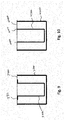
- FIG. 9 demonstrates nested container system with the lipped inner container 3400 with lip 3311 of the present invention, as opposed to alternate invention embodiment shown in FIG. 10 , wherein inner container 4300 does not use a lip.
- Outer container 3200 contains inner container 3300 . The two are joined by generally planar lid 3400 .
- FIG. 10 demonstrates an alternative embodiment without lip.
- Outer container 4200 nests inner container 4300 , the two of which are sealed jointly by lid 4400 .
- lip 3311 and edge 3310 of FIG. 9 combine at single edge 4410 .
- the perforation is meant to run along single edge 4410 , in a lid embodiment, such as those shown above, or as otherwise known to be useful by one skilled in the art.
- perforation generally refers to any characteristic known in the art for a lid, such as a foil lid, to have a predetermined tear point/line.
- perforated perforation refers literally to a hole or set of holes or apertures in the perforation that provide for controlled tearing of the lid.
Abstract
A nested set of containers sealed with a single lid. The lid contains at least one perforation, or weak section, to allow the lid to tear along the perforation at a point between the edge of the outer container and the edge of the inner container, so that removing the lid to the perforation allows for the inner container to remain sealed. The remaining seal outer container edge can then be easily removed without breaking the seal on the inner container. In one embodiment, two or more perforations may be included, each with an adjacent tab to ease removal. The invention includes a method of removing the lid in such a way that the perforation provide for ease of access to the outer container without breaching the inner container.
Description
- The present application is a Continuation-in-Part (CIP) related to and claiming priority from non-provisional U.S. patent application Ser. No 13/545,481, pending non-provisional U.S. patent application Ser. No. 14/535,911, filed Nov. 7, 2014, and U.S. Provisional Patent Applications Nos. 62/110,052 and 62/200,583, filed Jan. 30, 2015 and Aug. 3, 2015, respectively, which applications are all incorporated herein by reference.
- The present invention relates in general to a container and lid system, and more particularly to a nest container and lid device and method for opening the same.
- Ready to drink has a clever package design that allows you to open your drink anywhere on Earth with a bonus snack inside. Most individual-servings of wine are packaged in smaller wineglasses to minimize headspace, to maintain the wine's flavor and improve shelf-life. There is a need for a lid that minimizes headspace and allows the wine, or another beverage, to be packed in an elegant standard-size stemless wineglass. A better package will maintain the feeling of a standard wineglass with a shatter-resistant PET. Removing the lid allows the wine to drop to a standard fil level, perfect for swirling and tasting wine.
- Made for the on-the-go lifestyle, ready to drink means you can have a glass of wine anywhere. Whether you are hiking, at a concert or sporting event, at the beach, traveling or just having a party, this glass is for you. The shatter-resistant material and sealed lid is made so it won't break or spill while en route to the final destination.
- Designed for on-the-go wine lovers, Ready to drink packaging offers individual wine servings with a perfectly paired snack to enhance the wine's natural flavors and satisfy your appetite. Crafted for travel, the standard size shatterproof stemless wine glass is easily packed, unbreakable, and spill-proof. Ready to drink packaging, is the perfect glass of wine, each and every time. To maintain freshness and prevent spills, the innovative lid is mechanically sealed. Once the lid is opened, the wine is at just the right level to swirl, taste, and allow the wine to breathe—without spilling a drop.
- Ready to drink packaging can be adapted to fit almost any type of glass. Easily adapted into a friendly shape for children, the ready to drink packaging can be filled with organic fruit juice or milk and paired with healthy snacks for moms on the go. All mom has to do is throw the drink in her bag and she has a drink and a snack in one. Ready to drink packaging is perfect for special occasions so children can have individual glasses of sparkling cider with a chocolate snack. It can be used as a party favor or personalized for a gift or promotional item. Ready to drink is easily stackable in either a refrigerator or ice chest and more special than a juice box.
- Ready to drink is just right when you want a single glass of wine. You can also mix and match, so if you want red and your friend wants white, you can have both, as each package can be customized in contents. Ready to drink safety material is the perfect container in places where glass containers are not allowed such as beaches, parks, etc.
- Many liquids spoil over time when exposed to oxygen and/or other atmospheric gases, and therefore must be stored in airtight storage containers that minimize the presence of oxygen and other atmospheric gases. For example, during the aging of wine, if a wine is not protected from both microbial spoilage and oxygen at all times it is likely to spoil. Protecting wine usually involves maintaining proper sulfur dioxide (SO2) levels and keeping containers full. Typically, containers for fluids, that are to be protected from atmospheric gases, maintain a space between the top surface of a stored fluid and the underside of the lid of the container (e.g., headspace) at a reduced pressure with respect to the container's ambient environment. This air space (e.g., headspace) must be maintained, to accommodate thermal expansion of the fluid to prevent the lid from being blown off of the container, or to prevent the container from rupturing.
- To minimize the amount of atmospheric gases trapped within the container during the bottling/packaging process, a lid is typically installed during a gas evacuation and/or displacement process. This is typically achieved by dispensing an inert gas into the space between the fluid and the lid as the lid is installed and/or by performing the lid installation operation within a vacuum chamber. For example, the headspaces in wine is purged by use of an inert gas to effectively remove the oxygen to greatly increase the amount of protection. However, it is nearly impossible to remove all atmospheric gases from the space maintained, between the fluid and the container lid. Typically, tall slender containers are preferred to short wider containers because fluids stored in taller slender containers have less exposed surface area to the entrapped atmospheric gases. In the case of wine, the oxygen uptake depends on the surface area exposed to oxygen and the exposure time. The rate of oxidation increases as the exposed surface area increases. As the rate of oxidation increases the shelf life of the wine decreases before the wine spoils.
- Often times, the containers themselves are used for consuming the beverages. Since the space between the lid and the fluid is minimized, to reduce the amount of entrapped atmospheric gases, the container is typically filled such that the fluid level is in close proximity to the rim of the container. However, this increases the likelihood that the beverage will spill when opened by a consumer. In addition, in the case where wine is served in a single use drinking container, having the fluid level near the rim of the container, once the lid is removed, makes it difficult for the user to swirl the wine in the glass so as to allow the wine to breathe and to increase the surface area of the wine to smell the wine's various aromas. In these cases it is desirable to have a greater distance between the top surface of the fluid and the rim of the container.
- Because lids are required to maintain a space between the fluid and the lid to accommodate thermal expansion, and because the lid installation process is typically performed in a vacuum chamber, a pressure differential exists between the inside of the container and its external environment. This pressure differential may pull atmospheric gases into the container over time. The oxygen uptake by a fluid depends on the surface area of the fluid exposed to the oxygen and the exposure time. As a result, tall slender containers are preferred for these fluids as opposed to short, wide containers, since taller, more slender containers result in the fluid having less exposed surface area to the space above. In order to accommodate the pressure differential of the lid and containers, both the container and lid walls must be thick enough to withstand the resultant pressures to prevent failure. This may drive up the weight and material usage, and thus increase the costs of the container and lid.
- Many production and distribution companies are striving to develop more complex and sophisticated packaging mechanisms for securing consumable liquids, such as wine and other beverages. Many of these packaged beverages to be sold and distributed throughout the world need a greater shelf life. Certain beverages, such as wine, require the consumable liquid be protected from atmospheric gases to preserve the inherent qualities and characteristics of the wine. Furthermore, certain beverages are typically paired with dry foodstuffs, often in bulky and/or disagreeable packaging. As such, a need exists for an air purging lid for protecting the liquid from atmospheric gases, as well as a combination package for a beverage and dry goods, which protects and separates the two for control, and ease of access.
- Accordingly, various device and method embodiments for a lid device are provided. In this latest set of embodiments, a nested center container preferably holds a dry content. The center container is placed within the outer container, along with a liquid. The remaining volume in the outer container is filled with an inert gas and/or (partial) vacuum. A generally planar top seal is placed over the opening of both containers.
- In one embodiment the lid is perforated along an arc, or opposite arcs, to provide partial separation to allow access to the outer container liquid while keeping the inner container sealed. Tabs may be located around the perimeter of the lids to provide handholds. Handholds may be placed along the same vector as the perforations to allow directed separation of the lid from the outer container while preserving the seal over the inner container. Further tabs may be located and misaligned with the perforations to allow for removing the lids from both containers in one pull. or to be used to finally remove the lid from the inner container once it has already been removed from the outer container.
- In another embodiment, the container lid contains two tabs, opposite one another, and preferably of various sizes. A first, preferably larger, tab provides access to the outer container and sits along a long perforation. The second tab is directly in contact with the edge of the inner container. A perforation circumscribes a portion, preferably a majority, of the inner container edge.
- In addition to the foregoing exemplary method embodiment, other exemplary system and apparatus embodiments were included in the prior applications and provide related advantages. The foregoing summary has been provided to introduce a selection of concepts in a simplified form.
-
FIG. 1 demonstrates a cross-section side-view of an embodiment of the present invention. -
FIG. 2 demonstrates a cross-section side-view of the exterior container portion noted as 2 ofFIG. 1 . -
FIG. 3 demonstrates inner container portion noted as 3 ofFIG. 1 . -
FIG. 4A demonstrates a lower perspective of an embodiment of the present invention. -
FIG. 4B demonstrates an upper perspective of an embodiment of the present invention. -
FIG. 5A demonstrates a top view of a lid of an embodiment of the present invention. -
FIG. 5B demonstrates a top view of a lid of an embodiment of the present invention. -
FIG. 5C demonstrates a top view of a lid of an embodiment of the present invention. -
FIG. 6 demonstrates a top view of a lid of an embodiment of the present invention. -
FIG. 7 demonstrates a top view of a lid of an embodiment of the present invention. -
FIG. 8 demonstrates a top view of a lid of an embodiment of the present invention. -
FIG. 9 demonstrates a cross-section side-view of an embodiment of the present invention. -
FIG. 10 demonstrates a cross-section side-view of an embodiment of the present invention. - A multiple chamber container, includes an outer chamber with an open top circumscribed by an edge. The outer container is adapted to contain an inner container, as well as a liquid and a gas. Solid material(s) may also be included or existing in the outer container, per choice of filling. The gas can be minimized whether by being crowded out by other components and/or via vacuum seal. The inner container is adapted to hold gas as well as, or in place of, liquid and/or dry goods products. The inner container also includes an open top circumscribed by an edge. When sealed with a generally planar lid, the inner and outer container edges are placed on the same plane and sealed with a flexible lid, as is known in the art, preferably a thin aluminum planar lid.
- The lid may include a partial circular perforation, or otherwise weak portions, that circumscribe all, or preferably part or parts, of the inner container lid edge. One or more tabs ma extend from the lid outer edge to provide for grips or handholds, that indicate to the consumer where to lift the lid so as to open the container. In combination, the consumer can selectively open and access the outer container while leaving the inner container seals via lid. The number of tabs, perforations, or where they are placed can vary based on the embodiment.
- Turning now to
FIG. 1 cross-section of amultiple chamber container 100 showsouter container 200,inner container 300, andlid 400. Outer container includesedge 210 and interior 201 which also containsinner container 300. Optionally, outer container may also contain a fluid 202, wherebyfluid 202 may interface with inner containerexterior surface 320. Additionally, a portion of the space withinouter container 200 may hold agas 203. Inner container also includes anedge 310 and interior 301. Both inner and outer container form cups with a single opening at the top alongedges lid 400, wherebylid 400 covers the concentric openings of the inner and outer containers, and mates vialid bottom side 403. Lid contains atop side 402 andlid edge 401. -
FIG. 2 demonstratesouter container 200 in isolation and cross-section, wherebyFIGS. 2 and 3 are separable portions fromFIG. 1 . As can be seen, wheninner container 300 is removed, additional space frees up, typically allowing gas to enter, and the liquid level 290 of any liquid/fluid 202 therein may decrease.Outer container 200 includes interior 201 andedge 210. Outer containertop opening aperture 220 provides access to contents therein.FIG. 3 showsinner container 300 withexterior surface 320 enclosing interior 301.Inner container 300 also includes anedge 310 to mate withlid 400 and expose lidtop side 402. - Looking further at
inner container 300,FIGS. 4A and 4B show an embodiment of the inner container andlid 400 of the present invention.Inner container 300 includesexterior surface 320 which includesbottom 321. Atedge 310 flange orlip 311 may be preferably included to provide additional surface area for contact withlid 400, wherebylip 311 meetssidewall 321 atbend 312.Lid 400 includes acircumference edge 401, which may include one or more, preferably extendingtabs perforations 500. Perforations include either aligned small indentations or apertures, or weaker material, or thinned material, in lid to provide for ease and priority of separation/tearing when specific tabs are lifted. For instance, access to the outer container may be provided by liftingtabs 440 andopposite tab 442 to the point that the lid separates from the outer container edge (not shown), but remnants remain oninner container edge 310. Lid may be fully separated from the outer container and completely in place on inner container edge so as to completely seal inner container while outer container can be accessed. Separate, if not at the same time, the lid can then be removed from inner container via tab ortabs 443 and/or 441. -
FIGS. 5A, 5B and 5C demonstrate thelid 400 of this particular embodiment in depth.Lid 400 includestabs outer edge 401. One or more perforations (here twoperforations FIGS. 5B and 5C below.Lid 400 interfaces with inner container (not shown) alonglip ring 311A which is defined by lipouter edge 310A andlip corner edge 312A. It is preferred that there be two perforations. As in this reference and throughout this specification, the term perforations should be read liberally to include weak points, weak lines, small consecutive apertures, and allow other known perforation types known in the art to provide for the utility as described in this and the incorporated references. Similarly, the lid would be comprised of a number of differing materials, as is known in the art, but is preferably a foil, preferably aluminum foil, that is flexible and preferably coated to prevent interaction with gas or liquid contained. - In this circular container/lid embodiment,
perforation 501 spans an arc alonglip ring 311A and is preferably equidistance between lipouter edge 310A andlip corner edge 312A.Perforation 501 preferably spans an arc length of ninety degrees, but will be less than 180 degrees and more than 0 degrees. Preferable are lengths ofperforation 501 are between 60 and 120 degrees, but more preferably between 80 and 100 degrees, or in any event these degrees are plus or minus 5 degrees.Perforation 501 must be at or beyondlip corner edge 312A. Perforation may be set along lipouter edge 310A, or even outside of lipouter edge 310A, but preferably less than 1 cm beyond the lip outer edge, preferably no more than 2 mm beyond lipouter edge 310A. In a preferred embodiment, the perforation is to be aligned on the foil such that it is between the lip inner edge and outer edge, preferably along the midline between the lip inner edge and lip outer edge. If not at midline, the perforation should be set somewhere within the range of midline to lip outer edge. - As shown in
FIGS. 5B and 5C , the method of removing the lids with the perforations (FIG. 5C ) and without the perforations (FIG. 5B ) can be demonstrated. To remove the inner container first, without uncovering it, first pull tab(s) 440 and/or 442. Given the stress onlid 400, when the lid is pulled bytab 440 toline 450, lid meets its first resistance (for instance glue) as the lid is attached to the inner container edge at 310A at the outer circumference ofinner container lip 311A. Similarly fromtab 442 to line 451. Pulling further would cause a loss of control to prevent opening the inner container altogether. When pullingside tabs lines - Circle X demonstrates the difference and area not uncovered in this lifting fashion. Any lift, even if not from tabs, will be met by resistance at the outermost edge of the adhesion at
inner container edge 310A. A higher force is required to overcome the adhesion at 311A and may result in premature opening of the inner container. - This is solved with
perforations tab 440, lid meets resistance atedge 310 A. Further force is required to overcome adhesion atlip 311A until reachingperforation 500, wherein lid will begin to tear alongperforation 500. Tear will extend to perforation ends 520, and lid will be removed along aline 450, while remaining sealed up toperforation 501. To complete removal, repeat steps attab 442. Theside tabs lines outer container edge 210 and can be easily removed in spots 210A, 210B, 210C, and 210D. -
FIGS. 6 and 7 demonstrate an alternative embodiment of the lid of the present invention.Lid 1400 includesfirst tab 1441 andsecond tab 1440 alongperiphery 1401. Furthermore,lid 1400 includes a singleelongated perforation 1500.Perforation 1500 extends in a semicircle or the large part of a circle from perforation ends 1501 to 1502. Preferably, perforation represents a single are that is at least 180 degrees, but more preferably between 220 and 320 degrees, or more preferably between 250 and 310 degrees, or even more preferably between 255 and 285 degrees, but most preferably at 270 degrees, but may be plus or minus 5 degrees.First tab 1441 is preferably larger thansecond tab 1440.Lid 1400 is first lifted bytab 1441, to tear atperforation 1500. An inner container can then be gently removed by lifted one end of the extended lid from the outer container, and avoid removing lid from the inner container opening. -
Lid 1400 is lifted fromtab 1441 to outer containerouter edge 1211, past outer container edge 1210A, until it reaches innercontainer lip edge 1311. The tab is pulled gently to separate a portion of innercontainer lip edge 1310A, until it reaches and tears atperforation 1500. Further pulling removeslid 1400 from a majority of outer container edge 1210A surrounding the length of perforation as the lid tears from perforation ends 1501 to 1502. The final portion ofouter container edge 1220 can then be separated fromlid 1400 by gently pulling up onsecond tab 1440, allowing removal of the inner container. Finally, as a separable item, inner container can be opened via removing remaininglid 1400 to inner containerinner lip edge 1312. - As shown in
FIG. 8 , an optional embodiment may include a set of three tabs around one large perforation. Lid 2000 includes innercontainer lip section 2100 andouter container section 2200 where the lid 2000 meets the nested containers (not shown).Inner lip section 2100 showsinner lip edge 2101 andouter lip edge 2102, or rim. Lid 2000 also includestabs - Dual access tabs, as shown may be preferably to a single tab as seen above
FIGS. 6-7 , as use of a thin foil for lid may lead to tearing as the tab is lifted to tear alongperforation 2500. Thin foil lids tends to tear generally, instead of specifically along the perforations, requiring additional tabs to avoid unnecessary stress.Tab 2441 can then be used to access inner container by releasing lid from the inner container lip. -
FIG. 9 demonstrates nested container system with the lippedinner container 3400 withlip 3311 of the present invention, as opposed to alternate invention embodiment shown inFIG. 10 , whereininner container 4300 does not use a lip.Outer container 3200 containsinner container 3300. The two are joined by generallyplanar lid 3400.FIG. 10 demonstrates an alternative embodiment without lip.Outer container 4200 nestsinner container 4300, the two of which are sealed jointly bylid 4400. In the embodiment shown inFIG. 10 ,lip 3311 and edge 3310 ofFIG. 9 combine atsingle edge 4410. In this embodiment, the perforation is meant to run alongsingle edge 4410, in a lid embodiment, such as those shown above, or as otherwise known to be useful by one skilled in the art. - As is used throughout this description, the term perforation generally refers to any characteristic known in the art for a lid, such as a foil lid, to have a predetermined tear point/line. The term perforated perforation refers literally to a hole or set of holes or apertures in the perforation that provide for controlled tearing of the lid.
Claims (19)
1. A multiple chamber container system for storage of separable elements comprising:
a. an inner container comprising a first opening, a first edge within a first plane said first edge defining said first opening, a lip extending from said first edge wherein said lip parallel to said first plane;
b. an outer container comprising a second opening, and a second edge within a second plane defining said second opening, and said outer container sized large enough to allow said inner container to be nested within said outer container;
whereby when said inner container is located within said outer container, said first plane and said second plane align; and
c. a flexible lid adapted to seal both inner container and said outer container along said first and second planes, said lid adhering to said first edge, said lip, and said second edge, said flexible lid further comprising:
at least a first perforation adapted to allow tearing of said flexible lid with a lower force than the remainder of said flexible lid, said at least one perforation aligned over a first section of said lip.
2. The multiple chamber container system for storage of separable elements of claim 1 wherein said flexible lid comprises a perimeter edge, said perimeter edge comprising at least as first tab extending from said perimeter edge.
3. The multiple chamber container system for storage of separable elements of claim 2 , wherein said at least one tab is aligned along a lid plane defined by at least a portion of said flexible lid.
4. The multiple chamber container system for storage of separable elements of claim 2 further comprising at least a second tab.
5. The multiple chamber container system for storage of separable elements of claim 4 whereby said at least second tab is positioned directly opposite said at least first tab.
6. The multiple chamber container system for storage of separable elements of claim 4 further comprising at least a third tab.
7. The multiple chamber container system for storage of separable elements of claim 6 further comprising at least a fourth tab.
8. The multiple chamber container system for storage of separable elements of claim 4 further comprising at least a second perforation aligned over a second portion of said lip.
9. The multiple chamber container system for storage of separable elements of claim 8 wherein said at least a first perforation extend over at least 60 degrees of an arc length along said lip, and said at least a second perforation extend over at least 60 degrees of an arc length along said lip, said at least first perforation and said at least second perforation covering distinct portions of said lip.
10. The multiple chamber container system for storage of separable elements of claim 4 , wherein said at least a first perforation extends at least 180 degrees of an arc length along said lip.
11. The multiple chamber container system for storage of separable elements of claim 10 wherein said at least a first perforation extends at least 250 degrees of an arc length along said lip.
12. The multiple chamber container system for storage of separable elements of claim 11 whereby said at least first tab is outside said at least a first perforation and said at least said second tab is positioned outside a remainder of said flexible lid, said remainder positioned in the remainder of said flexible lid that is not outside said at least a first perforation.
13. A multiple chamber container system for storage of separable elements comprising:
a. an inner container comprising a first opening, a first edge within a first plane said first edge along said first opening;
b. an outer container comprising a second opening, and a second edge within a second plane along said second opening, and said outer container sized large enough to allow said inner container to be nested within said outer container;
whereby when said inner container is located within said outer container, said first plane and said second plane align; and
c. a flexible lid adapted to seal both inner container and said outer container along said first and second planes, said lid adhering to said first edge and said second edge, said flexible lid further comprising:
at least a first perforation adapted to allow tearing of said :flexible lid with a lower force than the remainder of said flexible lid, said at least one perforation aligned near said first edge.
14. A method of removing a nested interior container from an exterior container, whereby both the interior and exterior containers each have a single opening defined by an edge, the interior and exterior containers being concurrently sealed via a perforated flexible lid, comprising the steps of:
a. Lifting an edge of the lid to remove the lid from at least a portion of the lid from at least a portion of the exterior edge;
b. Partially tearing the lid along a perforation between the exterior edge and the interior edge;
c. Removing the remainder of the lid from the exterior lid, while leaving the lid over the entire edge of the interior container;
d. Extracting the sealed interior container from within the exterior container; and
e. Opening the interior container by removing the lid from the interior edge.
15. The method of claim 14 wherein after the step of partially tearing the lid further comprising the step of partially tearing the lid along a second separable perforation, wherein the second separable perforation is between the exterior edge and the interior edge.
16. The method of claim 14 wherein the step of partially tearing comprises tearing an arc length of at least 180 degrees around the interior edge.
17. The method of claim 16 wherein the step of partially tearing comprises tearing an arc length of at least 270 degrees around the interior edge.
18. The method of claim 14 wherein said step of lifting an edge is preceding by a step of grasping a tab adjacent to the perforation in the lid.
18. The method of claim 18 wherein said step of removing the remainder is preceding by a step of grasping a second tab, the second tab not adjacent to a perforation.
Priority Applications (1)
| Application Number | Priority Date | Filing Date | Title |
|---|---|---|---|
| US15/012,766 US20160143467A1 (en) | 2012-07-10 | 2016-02-01 | Air Purging Lid |
Applications Claiming Priority (5)
| Application Number | Priority Date | Filing Date | Title |
|---|---|---|---|
| US13/545,481 US20140014613A1 (en) | 2012-07-10 | 2012-07-10 | Air purging lid |
| US14/535,911 US20150102042A1 (en) | 2012-07-10 | 2014-11-07 | Air Purging Lid |
| US201562110052P | 2015-01-30 | 2015-01-30 | |
| US201562200583P | 2015-08-03 | 2015-08-03 | |
| US15/012,766 US20160143467A1 (en) | 2012-07-10 | 2016-02-01 | Air Purging Lid |
Related Parent Applications (1)
| Application Number | Title | Priority Date | Filing Date |
|---|---|---|---|
| US13/545,481 Continuation-In-Part US20140014613A1 (en) | 2012-07-10 | 2012-07-10 | Air purging lid |
Publications (1)
| Publication Number | Publication Date |
|---|---|
| US20160143467A1 true US20160143467A1 (en) | 2016-05-26 |
Family
ID=56008994
Family Applications (1)
| Application Number | Title | Priority Date | Filing Date |
|---|---|---|---|
| US15/012,766 Abandoned US20160143467A1 (en) | 2012-07-10 | 2016-02-01 | Air Purging Lid |
Country Status (1)
| Country | Link |
|---|---|
| US (1) | US20160143467A1 (en) |
Cited By (3)
| Publication number | Priority date | Publication date | Assignee | Title |
|---|---|---|---|---|
| USD961332S1 (en) * | 2020-02-06 | 2022-08-23 | Eazy-Pz, Llc | Toddler feeding cup |
| US11759035B2 (en) | 2021-01-12 | 2023-09-19 | Instant Brands Holdings Inc. | Silicone food and beverage storage containers |
| USD1022604S1 (en) | 2022-01-11 | 2024-04-16 | Instant Brands Holdings Inc. | Combined food and beverage storage container |
Citations (18)
| Publication number | Priority date | Publication date | Assignee | Title |
|---|---|---|---|---|
| US1609447A (en) * | 1923-02-12 | 1926-12-07 | Orange Crush Company | Compartment bottle |
| US1780728A (en) * | 1929-01-09 | 1930-11-04 | Packer Mfg Co Inc | Bottle structure |
| US2086073A (en) * | 1936-04-24 | 1937-07-06 | Dan L Francescon | Aging potable liquids in glass containers |
| US2352951A (en) * | 1941-08-27 | 1944-07-04 | Geria Andrew | Chemically heated liquid container |
| US2740575A (en) * | 1953-02-25 | 1956-04-03 | Rene J Fontaine | Dispensing container |
| US3235165A (en) * | 1964-03-02 | 1966-02-15 | Mildred J Jackson | Sealing means |
| US3580409A (en) * | 1969-10-09 | 1971-05-25 | Henry J Soboleski | Fruit and vegetable jar suppressor device |
| US4340138A (en) * | 1980-08-05 | 1982-07-20 | Daniel Bernhardt | Multiple compartment multiple seal container |
| US4456164A (en) * | 1982-05-18 | 1984-06-26 | Keyes Fibre Company | Deliddable ovenable container |
| US5042681A (en) * | 1989-01-19 | 1991-08-27 | Schmalbach-Lubeca Ag | Compartmented easy open package |
| US5315811A (en) * | 1991-05-30 | 1994-05-31 | Drug Plastics & Glass Company, Inc. | Method of packaging with an outer container having a container insert for holding a predetermined volume of material |
| US5375698A (en) * | 1993-05-07 | 1994-12-27 | Allergan, Inc. | Prefilled, resealable contact lens container |
| US20030129284A1 (en) * | 2002-01-10 | 2003-07-10 | Admiralty Island Fisheries, Inc. D.B.A. Aqua Star | Shrimp ring |
| US20050266122A1 (en) * | 2003-02-13 | 2005-12-01 | Fabio Franceschi | Capsule to be used to prepare an infused beverage |
| US20060102630A1 (en) * | 2002-08-14 | 2006-05-18 | Firestar Ag | Fuel tin |
| US20080302678A1 (en) * | 2005-03-30 | 2008-12-11 | Rodney Darryl Hunwisk | Edible Food Composition and Various Packaging Arrangments |
| US20110132781A1 (en) * | 2009-12-03 | 2011-06-09 | By The Glass, Llc | Combined wine glass and wine bottle package |
| US20110174814A1 (en) * | 2010-01-19 | 2011-07-21 | Pepsico, Inc. | Collapsible container |
-
2016
- 2016-02-01 US US15/012,766 patent/US20160143467A1/en not_active Abandoned
Patent Citations (18)
| Publication number | Priority date | Publication date | Assignee | Title |
|---|---|---|---|---|
| US1609447A (en) * | 1923-02-12 | 1926-12-07 | Orange Crush Company | Compartment bottle |
| US1780728A (en) * | 1929-01-09 | 1930-11-04 | Packer Mfg Co Inc | Bottle structure |
| US2086073A (en) * | 1936-04-24 | 1937-07-06 | Dan L Francescon | Aging potable liquids in glass containers |
| US2352951A (en) * | 1941-08-27 | 1944-07-04 | Geria Andrew | Chemically heated liquid container |
| US2740575A (en) * | 1953-02-25 | 1956-04-03 | Rene J Fontaine | Dispensing container |
| US3235165A (en) * | 1964-03-02 | 1966-02-15 | Mildred J Jackson | Sealing means |
| US3580409A (en) * | 1969-10-09 | 1971-05-25 | Henry J Soboleski | Fruit and vegetable jar suppressor device |
| US4340138A (en) * | 1980-08-05 | 1982-07-20 | Daniel Bernhardt | Multiple compartment multiple seal container |
| US4456164A (en) * | 1982-05-18 | 1984-06-26 | Keyes Fibre Company | Deliddable ovenable container |
| US5042681A (en) * | 1989-01-19 | 1991-08-27 | Schmalbach-Lubeca Ag | Compartmented easy open package |
| US5315811A (en) * | 1991-05-30 | 1994-05-31 | Drug Plastics & Glass Company, Inc. | Method of packaging with an outer container having a container insert for holding a predetermined volume of material |
| US5375698A (en) * | 1993-05-07 | 1994-12-27 | Allergan, Inc. | Prefilled, resealable contact lens container |
| US20030129284A1 (en) * | 2002-01-10 | 2003-07-10 | Admiralty Island Fisheries, Inc. D.B.A. Aqua Star | Shrimp ring |
| US20060102630A1 (en) * | 2002-08-14 | 2006-05-18 | Firestar Ag | Fuel tin |
| US20050266122A1 (en) * | 2003-02-13 | 2005-12-01 | Fabio Franceschi | Capsule to be used to prepare an infused beverage |
| US20080302678A1 (en) * | 2005-03-30 | 2008-12-11 | Rodney Darryl Hunwisk | Edible Food Composition and Various Packaging Arrangments |
| US20110132781A1 (en) * | 2009-12-03 | 2011-06-09 | By The Glass, Llc | Combined wine glass and wine bottle package |
| US20110174814A1 (en) * | 2010-01-19 | 2011-07-21 | Pepsico, Inc. | Collapsible container |
Cited By (5)
| Publication number | Priority date | Publication date | Assignee | Title |
|---|---|---|---|---|
| USD961332S1 (en) * | 2020-02-06 | 2022-08-23 | Eazy-Pz, Llc | Toddler feeding cup |
| US11759035B2 (en) | 2021-01-12 | 2023-09-19 | Instant Brands Holdings Inc. | Silicone food and beverage storage containers |
| USD1022604S1 (en) | 2022-01-11 | 2024-04-16 | Instant Brands Holdings Inc. | Combined food and beverage storage container |
| USD1022605S1 (en) | 2022-01-11 | 2024-04-16 | Instant Brands Holdings Inc. | Combined food and beverage storage container |
| USD1022606S1 (en) | 2022-01-11 | 2024-04-16 | Instant Brands Holdings Inc. | Combined food and beverage storage container |
Similar Documents
| Publication | Publication Date | Title |
|---|---|---|
| US9156587B2 (en) | Multiple sealed beverage vessels in a case | |
| US9888795B2 (en) | Single serve beverage container | |
| US2740575A (en) | Dispensing container | |
| US6277422B1 (en) | Beverage container and closure therefor which can serve as a coaster | |
| US10070708B2 (en) | Combination beverage and storage container with movable closure | |
| US20010022304A1 (en) | Container | |
| CN105307950A (en) | Packaging container | |
| WO2008020301A1 (en) | A drinking vessel | |
| US20180257818A1 (en) | Packaged food material, stack, and packaged stack | |
| US20160143467A1 (en) | Air Purging Lid | |
| KR20090012799U (en) | A cap for drink container | |
| WO2020078256A1 (en) | Stackable container with built-in channel | |
| KR200491426Y1 (en) | Take-out A disposable receptacle | |
| CN208188948U (en) | A kind of bulk beverage vending machine | |
| KR200429596Y1 (en) | A container for drink | |
| KR200487454Y1 (en) | Instant food set | |
| WO2016173908A1 (en) | A package assembly and a method for producing a package assembly | |
| JP5046112B2 (en) | Packaging containers and straws | |
| KR200202714Y1 (en) | Receptacle | |
| US9975662B1 (en) | Multi-chambered drink container | |
| KR20170047895A (en) | Up and down separating type drink container | |
| AU2015201091B2 (en) | Single serve beverage container | |
| EP1254847A1 (en) | A container | |
| CN109689512A (en) | Beverage container | |
| KR20070036327A (en) | An airtight cap bonded with metal pull tabs and it's apparatus |
Legal Events
| Date | Code | Title | Description |
|---|---|---|---|
| STCB | Information on status: application discontinuation |
Free format text: ABANDONED -- FAILURE TO RESPOND TO AN OFFICE ACTION |