US2034603A - Signal lens - Google Patents
Signal lens Download PDFInfo
- Publication number
- US2034603A US2034603A US709723A US70972334A US2034603A US 2034603 A US2034603 A US 2034603A US 709723 A US709723 A US 709723A US 70972334 A US70972334 A US 70972334A US 2034603 A US2034603 A US 2034603A
- Authority
- US
- United States
- Prior art keywords
- lens
- reflectors
- lenses
- portions
- lens member
- Prior art date
- Legal status (The legal status is an assumption and is not a legal conclusion. Google has not performed a legal analysis and makes no representation as to the accuracy of the status listed.)
- Expired - Lifetime
Links
- 238000005286 illumination Methods 0.000 description 8
- 239000011521 glass Substances 0.000 description 5
- 125000006850 spacer group Chemical group 0.000 description 3
- 239000000463 material Substances 0.000 description 2
- VYZAMTAEIAYCRO-UHFFFAOYSA-N Chromium Chemical compound [Cr] VYZAMTAEIAYCRO-UHFFFAOYSA-N 0.000 description 1
- 238000005266 casting Methods 0.000 description 1
- 150000001768 cations Chemical class 0.000 description 1
- 239000004568 cement Substances 0.000 description 1
- 229910052804 chromium Inorganic materials 0.000 description 1
- 239000011651 chromium Substances 0.000 description 1
- 238000010276 construction Methods 0.000 description 1
- 229910052751 metal Inorganic materials 0.000 description 1
- 239000002184 metal Substances 0.000 description 1
- 238000000465 moulding Methods 0.000 description 1
- 229910052709 silver Inorganic materials 0.000 description 1
- 239000004332 silver Substances 0.000 description 1
Images
Classifications
-
- G—PHYSICS
- G02—OPTICS
- G02B—OPTICAL ELEMENTS, SYSTEMS OR APPARATUS
- G02B5/00—Optical elements other than lenses
- G02B5/12—Reflex reflectors
- G02B5/126—Reflex reflectors including curved refracting surface
-
- Y—GENERAL TAGGING OF NEW TECHNOLOGICAL DEVELOPMENTS; GENERAL TAGGING OF CROSS-SECTIONAL TECHNOLOGIES SPANNING OVER SEVERAL SECTIONS OF THE IPC; TECHNICAL SUBJECTS COVERED BY FORMER USPC CROSS-REFERENCE ART COLLECTIONS [XRACs] AND DIGESTS
- Y10—TECHNICAL SUBJECTS COVERED BY FORMER USPC
- Y10S—TECHNICAL SUBJECTS COVERED BY FORMER USPC CROSS-REFERENCE ART COLLECTIONS [XRACs] AND DIGESTS
- Y10S362/00—Illumination
- Y10S362/812—Signs
Definitions
- the invention relates to lens and more parignates an inner lens member formed of glass, ticularly to lenses used in traflfic danger signals. preferably clear glass, or other suitable material,
- the general object of the invention is to proand-6 designates an outer lens member, prefervide a signal lens which may be illuminated by ably colored glass such as red or green glass or reflection or by direct illumination, and when other. suitable material, cooperating with the 5 directly illuminated will still maintain a subinner lens member to form the lens structure. stantially full field of illumination. More par-
- the inner lens member 5 is provided with a ticularly the invention is designed to provide plurality of recesses or shallow pockets 1 in which certain improvements over my copending appliopaque reflectors 8 are mounted. Each reflector cation Serial No. 679,599, filed July 10, 1933.
- Ac- 8 may be cemented to the lens 5 by cement 9 10 cording to the present invention the lens is having portions thereof disposed in grooves H1 in made in two parts, an inner part and an outer said lens or the reflectors may be molded into the part, the outer part preferably being capable of lens during the casting operation. adjustable spacing from the inner part.
- the outer lens member includes a series of inner part has reflectors mounted or incorporated buttontype lenses II formed integral with the 15 thereon which cooperate with button type lenses rest of this lens member and so disposed thereon formed as integral portions of the outer part. as to line up with the reflectors 8 in the pockets
- Each reflector is tion are; preferably a conically curved sheet metal stamp- 1.
- the button lens being part of the outer lens ing, either silver or chromium plated. 20 member itself, the usual problem of cementing When the two lens members 5 and 6 are aseach lens in place is eliminated.
- the reflectors are lined up or 2.
- the molding problem is simplified in that keep the focus with the button lenses l I in the there are no deep pockets to form.
- outer lens member by means of a suitable cen- 35 3.
- the construction is more economical, and tering device such as notches I 5 in the lens accidental breakage will usually be confined to edges.
- the outer and inner lens members are the outer lens member, thus saving the expense preferably not cemented together, but are of replacing or repairing the more expensive inner clamped together when assembled into a suitable lens member. signal housing.
- the inner, preferably clear glass, lens meming thickness may be inserted between the lens 30 ber may be used with any desired color outer lens members to vary the focus of the button rem b flectors. Shallow focus or small spacing favors 5. More light from the rear illumination source angle of reflection, and deep focus or wider spacpasses through the outer lens member to employ ing favors intensity of reflection.
- the reflectors may be polished at any time through the lens portions ll of the outer lens 40 by removing the inner lens member from its asmember 6 and intensified by the action of these 40 sembly. lenses in the. usual manner, focal distance being 7. Intensity and angle of reflection may be varied as previously described by the use of the varied by means of spacer gaskets between the spacers l2.
- the lens portions ll may be artwo lens members. ranged in the form of letters or indicating symbols
- the invention further consists in the several of various kinds. For example, I have shown in 45 features hereinafter set forth and more particu- Fig. 3 a lens provided with buttons arranged to larly defined by claims at the conclusion hereof.
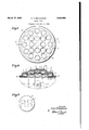
- Fig. 1 is a plan view of a lens structure em- When the full diameter illumination of the lens 60 bodying the invention; is desired the light rays from a lamp source, such Fig. 2 is a detail vertical sectional view taken as l3, find their way through the whole lens on the line 2-2 of Fig. 1; structure in spite of the opaque inserted reflectors Fig. 3 is a detail plan view showing a modificasince the light may passthrough the portions tion. of the inner lens bounding these reflectors and Referring to Figs.
- the numeral 5 desthen through the button lens portions II and the u bounding portions of such lenses of the outer lens member 6 as shown by the arrows N. If now for any reason the light source should be cut out, the lens structure immedLiately becomes a reflecting signal, and the button lens portions I l are used with the lens body as a support. If the illumination of the signal is not too bright, the light beams of car head lights will, upon contacting the reflecting part of the lens build up the intensity of the signal considerably. This makes it possible to use lamps of lower voltage than usually employed in traflic danger signals, and it will also provide a signal having a flashing elfect to the drivers vision. 4
- an inner lamp lens member provided with recesses, reflectors mounted in said recesses, and an outer lamp lens having a plurality of button type lens formed therein and focally spaced from said reflectors to form a plurality of reflecting units, said inner lens having portions in light conductive spaced relation with the button lenses and spaces therebetween of the outer lens to provide complete lamp illumination thereof,
- an inner lamp lens member having a generally convexly curved surface provided with recesses, reflectors mounted in said recesses, and an outer lamp lens having a plurality of button type lenses formed therein and focally spaced from saidreflectors to form a plurality of reflecting units, said outer lens having a generally convexly curved contour, said inner lens having portions in light conductive spaced relation with the button lenses and spaces therebetween of the outer lens to provide'complete lamp illumination thereof.
Description
March 17, 19 36. Q v, E Q 2,034,603
SIGNAL LENS Original Filed Feb. 5, 1934 VENTOR.
CaQNbmammm 1M ATTORNEY Patented Mar. 17, 1936 I UNITED STATES PATENT OFFICE SIGNAL LENS Carl V. Bergstrom, Milwaukee, Wis., assignor to Corning Glass Works, Corning, N. Y., a corporation of New York Application February 5, 1934, Serial No. 709,723 Renewed August-24, 1935 3 Claims. (01. 88-82) The invention relates to lens and more parignates an inner lens member formed of glass, ticularly to lenses used in traflfic danger signals. preferably clear glass, or other suitable material,
The general object of the invention is to proand-6 designates an outer lens member, prefervide a signal lens which may be illuminated by ably colored glass such as red or green glass or reflection or by direct illumination, and when other. suitable material, cooperating with the 5 directly illuminated will still maintain a subinner lens member to form the lens structure. stantially full field of illumination. More par- The inner lens member 5 is provided with a ticularly the invention is designed to provide plurality of recesses or shallow pockets 1 in which certain improvements over my copending appliopaque reflectors 8 are mounted. Each reflector cation Serial No. 679,599, filed July 10, 1933. Ac- 8 may be cemented to the lens 5 by cement 9 10 cording to the present invention the lens is having portions thereof disposed in grooves H1 in made in two parts, an inner part and an outer said lens or the reflectors may be molded into the part, the outer part preferably being capable of lens during the casting operation. adjustable spacing from the inner part. The The outer lens member includes a series of inner part has reflectors mounted or incorporated buttontype lenses II formed integral with the 15 thereon which cooperate with button type lenses rest of this lens member and so disposed thereon formed as integral portions of the outer part. as to line up with the reflectors 8 in the pockets The advantages of the multi-part lens construcl of the inner lens member 5. Each reflector is tion are; preferably a conically curved sheet metal stamp- 1. The button lens being part of the outer lens ing, either silver or chromium plated. 20 member itself, the usual problem of cementing When the two lens members 5 and 6 are aseach lens in place is eliminated. sembled together, the reflectors are lined up or 2. The molding problem is simplified in that keep the focus with the button lenses l I in the there are no deep pockets to form. outer lens member by means of a suitable cen- 35 3. The construction is more economical, and tering device such as notches I 5 in the lens accidental breakage will usually be confined to edges. The outer and inner lens members are the outer lens member, thus saving the expense preferably not cemented together, but are of replacing or repairing the more expensive inner clamped together when assembled into a suitable lens member. signal housing. Spacers or gaskets l2 of vary- 4. The inner, preferably clear glass, lens meming thickness may be inserted between the lens 30 ber may be used with any desired color outer lens members to vary the focus of the button rem b flectors. Shallow focus or small spacing favors 5. More light from the rear illumination source angle of reflection, and deep focus or wider spacpasses through the outer lens member to employ ing favors intensity of reflection. The lens memthe full diameter of illumination because the bers 5 and 6 are each of generally convexly 35 spaces around the reflectors are open and the curved form. light does not have to pass through the side of The light from the head light beams of an aubutton lens reflector pockets. tomobile are reflected by the reflectors 8 back 6. The reflectors may be polished at any time through the lens portions ll of the outer lens 40 by removing the inner lens member from its asmember 6 and intensified by the action of these 40 sembly. lenses in the. usual manner, focal distance being 7. Intensity and angle of reflection may be varied as previously described by the use of the varied by means of spacer gaskets between the spacers l2. The lens portions ll may be artwo lens members. ranged in the form of letters or indicating symbols The invention further consists in the several of various kinds. For example, I have shown in 45 features hereinafter set forth and more particu- Fig. 3 a lens provided with buttons arranged to larly defined by claims at the conclusion hereof. form the letters RR to be used as a warning for In the drawing; a a railroad crossing. Fig. 1 is a plan view of a lens structure em- When the full diameter illumination of the lens 60 bodying the invention; is desired the light rays from a lamp source, such Fig. 2 is a detail vertical sectional view taken as l3, find their way through the whole lens on the line 2-2 of Fig. 1; structure in spite of the opaque inserted reflectors Fig. 3 is a detail plan view showing a modificasince the light may passthrough the portions tion. of the inner lens bounding these reflectors and Referring to Figs. 1 and 2, the numeral 5 desthen through the button lens portions II and the u bounding portions of such lenses of the outer lens member 6 as shown by the arrows N. If now for any reason the light source should be cut out, the lens structure immedLiately becomes a reflecting signal, and the button lens portions I l are used with the lens body as a support. If the illumination of the signal is not too bright, the light beams of car head lights will, upon contacting the reflecting part of the lens build up the intensity of the signal considerably. This makes it possible to use lamps of lower voltage than usually employed in traflic danger signals, and it will also provide a signal having a flashing elfect to the drivers vision. 4
The invention is not to be limited to any particular form or arrangement of parts except in so far as such limitations are included in the claims.
All claims made herein are restricted to two separate elements, one having a plurality of reflectors and the other having a plurality of lenses carried thereby, as claims not so limited are made in my said other application Serial No. 679,599.
What I claim as my invention is:
1. In a device of the character described, the combination of an inner lamp lens member, and an outer lamp lens member, said inner lens memher having reflectors mounted thereon, said outer lens member having smaller lens formed in it cooperating with said reflectors to form a plurality of reflecting units, said lens members having light conductive spaces between said reflectors and smaller lenses, in light conductive relation with portions of said inner lens, said lens members and said spaces providing light conductivity through the entire assembly.
2. Ina device of the character described, the combination of an inner lamp lens member provided with recesses, reflectors mounted in said recesses, and an outer lamp lens having a plurality of button type lens formed therein and focally spaced from said reflectors to form a plurality of reflecting units, said inner lens having portions in light conductive spaced relation with the button lenses and spaces therebetween of the outer lens to provide complete lamp illumination thereof,
3. In a device of the character described, the combination of an inner lamp lens member having a generally convexly curved surface provided with recesses, reflectors mounted in said recesses, and an outer lamp lens having a plurality of button type lenses formed therein and focally spaced from saidreflectors to form a plurality of reflecting units, said outer lens having a generally convexly curved contour, said inner lens having portions in light conductive spaced relation with the button lenses and spaces therebetween of the outer lens to provide'complete lamp illumination thereof.
CARL V. BERGSTROM.
Priority Applications (1)
| Application Number | Priority Date | Filing Date | Title |
|---|---|---|---|
| US709723A US2034603A (en) | 1934-02-05 | 1934-02-05 | Signal lens |
Applications Claiming Priority (1)
| Application Number | Priority Date | Filing Date | Title |
|---|---|---|---|
| US709723A US2034603A (en) | 1934-02-05 | 1934-02-05 | Signal lens |
Publications (1)
| Publication Number | Publication Date |
|---|---|
| US2034603A true US2034603A (en) | 1936-03-17 |
Family
ID=24851067
Family Applications (1)
| Application Number | Title | Priority Date | Filing Date |
|---|---|---|---|
| US709723A Expired - Lifetime US2034603A (en) | 1934-02-05 | 1934-02-05 | Signal lens |
Country Status (1)
| Country | Link |
|---|---|
| US (1) | US2034603A (en) |
Cited By (3)
| Publication number | Priority date | Publication date | Assignee | Title |
|---|---|---|---|---|
| US2503509A (en) * | 1947-12-10 | 1950-04-11 | Frederick S Rader | Oscillating signal reflector for vehicles |
| US3041600A (en) * | 1957-01-31 | 1962-06-26 | Gumpertz | Character projection apparatus |
| US20070091615A1 (en) * | 2005-10-25 | 2007-04-26 | Chi-Tang Hsieh | Backlight module for LCD monitors and method of backlighting the same |
-
1934
- 1934-02-05 US US709723A patent/US2034603A/en not_active Expired - Lifetime
Cited By (3)
| Publication number | Priority date | Publication date | Assignee | Title |
|---|---|---|---|---|
| US2503509A (en) * | 1947-12-10 | 1950-04-11 | Frederick S Rader | Oscillating signal reflector for vehicles |
| US3041600A (en) * | 1957-01-31 | 1962-06-26 | Gumpertz | Character projection apparatus |
| US20070091615A1 (en) * | 2005-10-25 | 2007-04-26 | Chi-Tang Hsieh | Backlight module for LCD monitors and method of backlighting the same |
Similar Documents
| Publication | Publication Date | Title |
|---|---|---|
| US4577260A (en) | Vehicle lamp assemblies | |
| US4371916A (en) | Motor-vehicle lamp with base area illumination | |
| US2034603A (en) | Signal lens | |
| US1874138A (en) | Signal lantern | |
| US2113829A (en) | Autocollimating signal device | |
| US2632095A (en) | Headlight lens | |
| US2380691A (en) | Black-out marker light | |
| US2088501A (en) | Signaling device | |
| US2141159A (en) | bergstrom | |
| US2215203A (en) | Motor vehicle headlight | |
| US1903385A (en) | Reflecting unit | |
| ES290546U (en) | Signaling light with colored light for automotive vehicles (Machine-translation by Google Translate, not legally binding) | |
| US2223059A (en) | Direction signal | |
| US2219203A (en) | Automobile signal | |
| US1795940A (en) | Tail-lamp glass | |
| US1889623A (en) | Combined light and signal | |
| US2350599A (en) | Headlight signal | |
| US1666041A (en) | Traffic signal | |
| US1415595A (en) | Signal device | |
| US2151279A (en) | Reflecting unit | |
| US1990223A (en) | Sectional reflector sign | |
| US1949503A (en) | Dual reflector | |
| US1780046A (en) | Headlight for vehicles | |
| US1348816A (en) | Illuminated sign | |
| US2114232A (en) | Searchlight |