US20420A - Smut-machine - Google Patents
Smut-machine Download PDFInfo
- Publication number
- US20420A US20420A US20420DA US20420A US 20420 A US20420 A US 20420A US 20420D A US20420D A US 20420DA US 20420 A US20420 A US 20420A
- Authority
- US
- United States
- Prior art keywords
- cylinder
- smut
- space
- fan
- blast
- Prior art date
- Legal status (The legal status is an assumption and is not a legal conclusion. Google has not performed a legal analysis and makes no representation as to the accuracy of the status listed.)
- Expired - Lifetime
Links
- 239000002184 metal Substances 0.000 description 6
- 238000009991 scouring Methods 0.000 description 4
- 238000004140 cleaning Methods 0.000 description 2
- 230000000875 corresponding Effects 0.000 description 2
- 238000010438 heat treatment Methods 0.000 description 2
Images

Classifications
-
- B—PERFORMING OPERATIONS; TRANSPORTING
- B02—CRUSHING, PULVERISING, OR DISINTEGRATING; PREPARATORY TREATMENT OF GRAIN FOR MILLING
- B02B—PREPARING GRAIN FOR MILLING; REFINING GRANULAR FRUIT TO COMMERCIAL PRODUCTS BY WORKING THE SURFACE
- B02B3/00—Hulling; Husking; Decorticating; Polishing; Removing the awns; Degerming
- B02B3/08—Hulling; Husking; Decorticating; Polishing; Removing the awns; Degerming by means of beaters or blades
Definitions
- the object of this invention is to obtain by the simplest possible means or arrangement of parts a combination of a fan and heating device so as to operate conjointly in the most efficient manner in cleaning grain from smut, dirt and the like.
- A represents a cylindrical hollow base the under side of which is open.
- a bridge tree (a) is placed having a step (b) at its center to receive the lower end of a vertical shaft B.
- C is a hollow cylinder the lower end of which encompasses the base A and D is a hollow cylinder which encompasses the cylinder O, a suitable space (0) being allowed between them.
- E is a fan box which is placed on the upper ends of the two cylinders C, D, and F, is the fan placed therein, said fan being on the shaft B which passes through the box IE, and has its upper bearing in a cross bar (cl) secured to the upper surface of the box.
- a driving pulley (e) is placed on the upper end of the shaft B.
- a cylinder F On the shaft B and within the cylinder C a cylinder F, is placed.
- the cylinder F is sufliciently Smaller in diameter than the cylinder C to allow radial beaters (f) to be attached to its periphery, the ends of the beaters extending to within a suitable distance of the inner side of the cylinder C.
- the inner side of the cylinder C is corrugated or fluted vertically and a feed pipe G extends through the sides of the two cylinders near their upper ends as shown in Fig. 1.
- the bottom plate (9) of the fan box E is perforated as shown at (it) (2') so that the space (0) between the two cylinders may communicate with the fan box and also the interior of the cylinder C.
- the lower part of the space (0) communicates with the external air by means of perforations (j) made in the base and the lower part of the cylinder C does not communicate directly with the external air but communicates by means of perforations (7a) with the lower part of the space (0) a short distance above the perforations (j).
- the fan box E is secured on the cylinders C, D, by screw rods
- the cylinder C may be constructed of cast metal and the cylinder D and fan box E of sheet metal or metal plate.
Description
1. GERMAN, J-r. & s. R. PERKINS.
Smut Mill.
No. 20,420. Patented June 1 1858.
I illlmlllll r: n r1 Z A y,
. l r V I l 2 71 UNITED STATES PATENT OFFICE.
JOHN GERMAN, JR., OF SOUTHFIELD, AND S. R. PERKINS, OF PONTIAC, MICHIGAN.
SMUT-MACHINE.
Specification of Letters Patent No. 20,420, dated June 1, 1858.
To all whom it may concern:
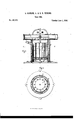
Be it known that we, JOHN GERMAN, J r., of Southfield, in the county. of Oakland and State of Michigan, and S. R. PERKINS, of Pontiac, in the county of Oakland and State of Michigan, have invented a new and Improved Smut-Mill; and we do hereby declare that the following is a full, clear, and exact description of the same, reference being had to the annexed drawings, making a part of this specification, in which Figure 1, is a vertical central section of our improvement. Fig. 2 is a horizontal section of ditto taken in the line (00) (m), Fig. 1.
Similar letters of reference indicate corresponding parts in the two figures.
The object of this invention is to obtain by the simplest possible means or arrangement of parts a combination of a fan and heating device so as to operate conjointly in the most efficient manner in cleaning grain from smut, dirt and the like.
To enable those skilled in the art to fully understand and construct our invention we will proceed to describe it.
A represents a cylindrical hollow base the under side of which is open. Within the base A, a bridge tree (a) is placed having a step (b) at its center to receive the lower end of a vertical shaft B.
C is a hollow cylinder the lower end of which encompasses the base A and D is a hollow cylinder which encompasses the cylinder O, a suitable space (0) being allowed between them.
E is a fan box which is placed on the upper ends of the two cylinders C, D, and F, is the fan placed therein, said fan being on the shaft B which passes through the box IE, and has its upper bearing in a cross bar (cl) secured to the upper surface of the box. A driving pulley (e) is placed on the upper end of the shaft B.
On the shaft B and within the cylinder C a cylinder F, is placed. The cylinder F, is sufliciently Smaller in diameter than the cylinder C to allow radial beaters (f) to be attached to its periphery, the ends of the beaters extending to within a suitable distance of the inner side of the cylinder C. The inner side of the cylinder C is corrugated or fluted vertically and a feed pipe G extends through the sides of the two cylinders near their upper ends as shown in Fig. 1.
The bottom plate (9) of the fan box E is perforated as shown at (it) (2') so that the space (0) between the two cylinders may communicate with the fan box and also the interior of the cylinder C. The lower part of the space (0) communicates with the external air by means of perforations (j) made in the base and the lower part of the cylinder C does not communicate directly with the external air but communicates by means of perforations (7a) with the lower part of the space (0) a short distance above the perforations (j). The fan box E is secured on the cylinders C, D, by screw rods The cylinder C may be constructed of cast metal and the cylinder D and fan box E of sheet metal or metal plate.
The operation is as follows :-Motion is given the shaft B in any proper manner and a draft or blast of air passes up through the space (a) as indicated by the red arrows and a blast passes up through the cylinder 0 as indicated by the black arrows. passes through the pipe G, into the cylinder G and is secured by the rotation of the cylinder F, the beaters (f) and inner corrugated or fluted surface of the cylinder G, effectuall'y breaking the smut balls and also scouring off the dirt which may adhere thereto, and the dirt and smut as it is pulverized and loosened by the scouring device is carried upward by the blast within said cylinder G into the fan box E from which it is ejected by the action of the fan as indicated by the arrow (1), see Fig. 1. In case however any smut or dirt should escape the action of the blast within the cylinder C, and pass down through the perforations (Z4) into the lower part of the space (0) the blast within said space will carry such portions upward within the fan box. It will thus be seen that the grain before leaving the machine, that is before passing out through the apertures (j), is subjected to two blasts generated by the same fan, and the escape of smut or dirt with the grain, which might probably occur in cases where the grain is very dirty or smutty, is consequently avoided because when the grain is subjected to the second blast in the lower part of the space The grain (0) there will be in any case but comparaspective of their arrangement the parts here- 15 tively a small amount of dirt or smut pass in described; but, 7 into said space (0) and therefore it will be We do claim as new and desire to secure readily carried up by the blast. by Letters Patent, 5 We are aware that smut mills have been de- The arrangement of an annular air space vised so as to subject the grain while passing (0) between the cylinders C, D, With openings 20 through them to two or more blasts and We (h, j, Z4) as and for the purpose herein set also are aware that rotating beaters and forth.
fluted cylinders have been used, but We are JOHN GERMAN, JR. 10 not aware that a fan has been used in conv S. R. PERKINS.
nection'with rotating heaters and cylinders Witnesses: so arranged as to form a simple, efiicient and HENRY S. BUEL, economical device, as herein described. We ROBERT C. KYLE,
do not claim therefore separately and irre- C. A. HOWARD.
Publications (1)
| Publication Number | Publication Date |
|---|---|
| US20420A true US20420A (en) | 1858-06-01 |
Family
ID=2085333
Family Applications (1)
| Application Number | Title | Priority Date | Filing Date |
|---|---|---|---|
| US20420D Expired - Lifetime US20420A (en) | Smut-machine |
Country Status (1)
| Country | Link |
|---|---|
| US (1) | US20420A (en) |
Cited By (3)
| Publication number | Priority date | Publication date | Assignee | Title |
|---|---|---|---|---|
| US20050066981A1 (en) * | 2003-09-30 | 2005-03-31 | Crooks Evon Llewellyn | Filtered cigarette incorporating an adsorbent material |
| US20050106975A1 (en) * | 2003-11-18 | 2005-05-19 | Sun Isle Casual Furniture, Llc | Woven articles from synthetic self twisted yarns |
| US20050194014A1 (en) * | 2004-03-04 | 2005-09-08 | Read Louis J.Jr. | Equipment and methods for manufacturing cigarettes |
-
0
- US US20420D patent/US20420A/en not_active Expired - Lifetime
Cited By (4)
| Publication number | Priority date | Publication date | Assignee | Title |
|---|---|---|---|---|
| US20050066981A1 (en) * | 2003-09-30 | 2005-03-31 | Crooks Evon Llewellyn | Filtered cigarette incorporating an adsorbent material |
| US20050106975A1 (en) * | 2003-11-18 | 2005-05-19 | Sun Isle Casual Furniture, Llc | Woven articles from synthetic self twisted yarns |
| US7892989B2 (en) | 2003-11-18 | 2011-02-22 | Casual Living Worldwide, Inc. | Woven articles from synthetic self twisted yarns |
| US20050194014A1 (en) * | 2004-03-04 | 2005-09-08 | Read Louis J.Jr. | Equipment and methods for manufacturing cigarettes |
Similar Documents
| Publication | Publication Date | Title |
|---|---|---|
| US20420A (en) | Smut-machine | |
| US36676A (en) | Improvement in grain-cleaners | |
| US25594A (en) | Smut-machine | |
| US440537A (en) | Ors to chisholm | |
| US15841A (en) | Smut-mill | |
| US23119A (en) | Smut-machine | |
| US1020377A (en) | Grain-cleaning machine. | |
| US27182A (en) | Smut-mill | |
| US13937A (en) | X g grain-cleaning machine | |
| US32578A (en) | Cleaning and feediitg geain to bur-millstones | |
| US21662A (en) | Improved grain-cleaning machine | |
| US24423A (en) | Grain-hulling machine | |
| US36311A (en) | Improvement in smut and grain-cleaning machines | |
| US24126A (en) | Separator for smut-machines | |
| US18179A (en) | Flouk-bolt | |
| US924447A (en) | Pea huller and separating machine. | |
| US57001A (en) | Improvement in smut-machines | |
| US19303A (en) | Improvement in flour-bolts | |
| US17966A (en) | Hominy-mill | |
| US17325A (en) | Machine for | |
| US36545A (en) | Improvement in smut-machines | |
| US11823A (en) | Smut-machine | |
| US23547A (en) | Smut-machiwe | |
| US21563A (en) | Improvement in smut-machines | |
| US23405A (en) | Smut-mill |