US2054809A - Air conditioning method and means - Google Patents
Air conditioning method and means Download PDFInfo
- Publication number
- US2054809A US2054809A US8603A US860335A US2054809A US 2054809 A US2054809 A US 2054809A US 8603 A US8603 A US 8603A US 860335 A US860335 A US 860335A US 2054809 A US2054809 A US 2054809A
- Authority
- US
- United States
- Prior art keywords
- liquid
- filaments
- air
- unit
- parallel
- Prior art date
- Legal status (The legal status is an assumption and is not a legal conclusion. Google has not performed a legal analysis and makes no representation as to the accuracy of the status listed.)
- Expired - Lifetime
Links
Images

Classifications
-
- F—MECHANICAL ENGINEERING; LIGHTING; HEATING; WEAPONS; BLASTING
- F24—HEATING; RANGES; VENTILATING
- F24F—AIR-CONDITIONING; AIR-HUMIDIFICATION; VENTILATION; USE OF AIR CURRENTS FOR SCREENING
- F24F6/00—Air-humidification, e.g. cooling by humidification
- F24F6/02—Air-humidification, e.g. cooling by humidification by evaporation of water in the air
- F24F6/04—Air-humidification, e.g. cooling by humidification by evaporation of water in the air using stationary unheated wet elements
-
- Y—GENERAL TAGGING OF NEW TECHNOLOGICAL DEVELOPMENTS; GENERAL TAGGING OF CROSS-SECTIONAL TECHNOLOGIES SPANNING OVER SEVERAL SECTIONS OF THE IPC; TECHNICAL SUBJECTS COVERED BY FORMER USPC CROSS-REFERENCE ART COLLECTIONS [XRACs] AND DIGESTS
- Y10—TECHNICAL SUBJECTS COVERED BY FORMER USPC
- Y10S—TECHNICAL SUBJECTS COVERED BY FORMER USPC CROSS-REFERENCE ART COLLECTIONS [XRACs] AND DIGESTS
- Y10S261/00—Gas and liquid contact apparatus
- Y10S261/11—Cooling towers
Landscapes
- Engineering & Computer Science (AREA)
- Chemical & Material Sciences (AREA)
- Combustion & Propulsion (AREA)
- Mechanical Engineering (AREA)
- General Engineering & Computer Science (AREA)
- Gas Separation By Absorption (AREA)
Description
Sept. 22, 1936.- w. 1., FLEISHER 2,054,809
- AIR CONDITIONING METHOD AND MEANS Filed Feb. 28, 1955 2 Sheets-Sheet 1 INVENT0R.I WALTER L. FZE/SHEE, BY
A TTORNEY.
Sept. 22, 1936. w 5H I 2,054,809
' AIR CONDITIONING METHOD AND MEANS Filed Feb. 28, 1935 2 Sheets-Sheet 2 1 5' .2.
if :38 l
INVENTOR. M14752 L FLE/sHE/e,
BY My;
- ATTORNEY.
Patented- Sept. 22, 1936 PATENT OFFICE Ant CONDITIONING rm'mon AND mans I Walter L. Fleisher, New York, N. Y. 1 Application February 28, 1935, Serial No. 8,603
18 Claims.
This inventionrelates to the conditioning of air and more particularly, to methods of and means for humidifying, dehumidifying and cleaning of air used both for industrial purposes and in air conditioning for human comfort.
A principal object of the invention is to provide an air or other gas conditioning apparatus utilizing a series of filaments of material bunched together substantially longitudinally. The filaments or fibres are preferably of non-absorbent, non-hygroscopic, non-corrodible, easily wetted, smooth surfaced material. In practice, applicant has found that thin filaments of glass meet the requirements effectively. The longitudinally bunched filaments are positioned to receive liquid .from any desired source, the liquid contacting with and flowing along or longitudinaly of the filaments. The fiow of a liquid particle along a filament serves to spread the particle over a relatively-large area to form, in the aggregate, a large amount of thin liquid film. The spread of liquid particles along the surfaces of' the bunched filaments prevents the formation of droplets, which otherwise would occur if the filaments were not bunched and the fiow of liquid not longitudinally of and along the filaments.
Air or other gas is circulated through and in contact with the filaments over which the liquid flows. The air (and the term air should be understood to include other gases as well) may be propelled in any desired direction, but preferably longitudinally of the filaments, and preferably in the same direction as the fiow of liquid. The velocity of the air when the air fiow is in the same direction as the liquid fiow, along the filaments, will aid the spread of liquid particles over-the. filaments. But, regardless of the direction of air flow, the primary consideration is the flow of liquid and air substantiallylongitudinally 'of the bunched parallel filaments, so that, in effect, the air course and the liquid course are in parallel with the parallel bunched filaments. As a result, the intimacy of contact between air aid liquid enables relatively large volumes oi air to be intensively conditioned to a desired degree by use of a relatively small volume filaments, bunched in parallel relation with re-" spect to one another, are packed in a basket orthe like. The filaments, in effect, divide the air stream passing through the basket into a great number of individual streams determined by the myriad passages formed by adjacent filaments.
The liquid flowing along the filaments acts in the 6 nature of a lubricant to aid the flow of air through the passages, the movement of air simultaneously aiding the liquid to spread over \a the filaments. In this manner, an optimum liquid-surface" relationship is established, so 10 that substantially all of the air is brought in contact with the liquid film toassure complete saturation of the air, although a quantity of liquid may be used not greatly in excess of that which the air can take up; and due to the parallel relal6 tionship of filaments, air course and liquid source, such optimum result is achieved with relatively small consumption of power.
The foregoing and other features of the invention will be apparent from the drawings diagrammatically showing illustrative forms of the invention, to be read in'connection with the accompanying description.
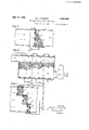
Fig. 1 diagrammatically illustrates a conditioning system in which a group of filaments are g5 bunched, air and liquid passing through the filaments in the same direction, the liquid being distributed equally over the mass of filaments;
Fig. 2 shows a unit filled with filaments, the unit being of triangular cross-sectional area and an arranged to receive liquid at different points thereof;
Fig. 3 shows a conditioning apparatus in which a plurality of units are employed, each unit containing a series of closely bunched fila- 35 ments, the liquid fed over one of the units being arranged to serve the others in succession; and
Fig. 4 is a modifiedv arrangement of the system shown in Fig. 3.
' In- Fig. 1, unit ll contains a series of sub-. stantially straight, bunched filaments. These are preferably of glass, hence, not hygroscopic,
' but may be of any suitable material. They are thin and placed in parallel and substantially 45 vertical relation with respect to one another so that air and liquid passing through the unit will flow longitudinally along the strands. A fewv strands are shown in a layer on top and at thebottom of the unit to act as supports for the vertical threads, forming the main unit, but these maybe replaced by equivalent means. The upper horizontal layer of filaments tends to distribute liquid deposited thereon, the liquid being held by capillarity to the filaments until a sl t-1n;
- cant thickness, yet admirably ficient mass accumulates, whereupon it gently runs down the adjacent vertical filaments. This aids even distribution over the whole unit. The bottom layer of horizontal filaments collects the liquid left after passage along the vertical filaments, this liquid then falling in large drops to sump 32 below. Thus, the bottom layer of filaments, beside afiording support to the vertical filaments, also acts as an eliminator, preventing minute droplets of water from being carried along by the air stream. Liquid is supplied from sump 32 by pump 33 to supply pipe 34 which floods the top of distributing pan 35. Thepan extends across the casing 10 and has a plurality of spaced orifices, each with a nozzle formed lip extending downwardly toward uid above the nozzles determining the rate of fiow therethrough. In many instances, the distributing pan need not be used and the liquid discharged directly upon the horizontal filaments, the purpose of pan 35 being to aid more even distribution of liquid over the unit. ,The liquid, after its course from pan to top horizontal filaments through the vertical filaments to bottom horizontalfilaments to sump 32, is recirculated and the process repeated in a continuous cycle. The filaments are closely packed to form a vast number of passages or tiny channels through which the liquid and air streams fiow. In effect, there will be an innumerable number of air passages and liquid passages. Hence, the liquid will be assured of intimate contact with the surfaces of the filaments and form in the aggregate a large area of unbroken film surface. gate liquid surface will be a maximum for the quantity of liquid employed, in view of the longitudinally grouped filaments, each of insignififitted to provide a maximum surface area for a minimum quantity of liquid. Since. all filaments are bunched together, so that the interstices between them are relatively small, liquid will not be permitted to escape without contact with the filaments and formation of desired liquid film.
The air-stream through casing 10 is in a direction the same as that of the flow of liquid. The air, however, moves at a velocity which will not destroy or negative the adhesive attraction between liquid and filaments. The films, in fact, are caused to spread by the air stream going in the same direction; the liquid acting in the nature of a lubricant to aid the flow of air through the tiny passages. Concurrent flow increases the tendency of vapor pressures of the conditioning liquid and treated gas to equalize; and also, reduces resistance to fiow of the gas. A counter current of airmay be employed, if desired, but it is preferred to fiow the air and liquid concurrently, to prevent building up the liquid into drops, or retard the spreading of the liquid to form film surface, as may occur under some conditions of air velocity. Although the.
filaments may deviate from the vertical, this deviation should not be so great that moisture will drop from the filaments instead of flowing along them to the bottom extremities.
By controlling the volume and temperature of the fluid, and/or the volume of air pulled by Ian 35, the condition of the air may be accurately regulated at minimum cost and maximum efficiency, due to the small cost of power 'by reason of low resistance through the unit and the reduced water requirements.
The use of filaments, grouped together, as described, assures positive cleaning of all the air ,for the air quantity passing unit II, the level of liq,-
The aggreor gas passing through the unit, because of the small diameter-large surface channels between filaments. Unlike scrubbers or units heretofore employed in which the exposed surface of liquid is by comparison relatively small (although the quantities of liquid used in such scrubbers is the surface here is a maximum through the unit, so that positive contact with the total air volume is had and maximum cleaning afforded. In the relatively larger),
practical operation of a device such as illustrated in Fig. 1, the .efficiency of cleaning will be reduced by employing filaments of larger diameter and increased by using smaller ones. The fact that the filaments .are not perfectly parallel, causes the air stream to impinge and deposit dirt particles and the like on the liquid film surfaces. Due to the rapid movement of the air in small streams of great turbulence over the flowing liquid surfaces, practically complete cleaning or removal of solid matter is accomplished.- The film tension causes agglomeration of particles to form masses of sufiicient'size and. mixed with sufficient water to prevent their being carried. away by the air stream. Further, if the filaments are of glass or other washable material, they may easily be cleaned by an ordinary solution of soapy ammonia water, and hence, be retained in service over long periods of time.
In Fig. 2, the unit I l consists of filaments, longitudinally grouped, but the filaments are of different lengths, to form a unit of varying thickness so that different portions of the air stream will be differently conditioned. The air stream is here shown transverse of the filaments, but a parallel flow of air and liquid is preferred. Liquid is supplied by header 3! to a plurality of distributing points. Individual valves I38 may meter the liquid fed to the unit at the several distributing points.
In Fig. 3, a plurality of units llc, lid and He, containing filaments of different lengths are employed. Screens, or the like, 38, act as supports for each unit. The air and liquid flow through the units in the same direction. Liquid from any desired source and at a desired condition, is supplied to distributor pan 39, which is of the same type as pan 35 of Fig. l. The liquid is thereby equally distributed to unit No, and after passing through the unit along the filaments thereof, it falls within the sump of section C. It is then pumped to and over pan 40, which distributes it over unit Nd; and finally, is pumped from the sump of section D to pan 4| which distributes it over unit Ile. It is, thereupon, reconditioned,
. recirculated in whole or in part to pan 39, or
otherwise disposed of. While three stages are shown, any number may be provided. Different portions of the air stream pulled through casing in by fan 42 will thereby be differently condi- Hf. After passing through this unit, the liquid tioned, but form a final mixture at a desired drains to a pan- 44 over. and serving unit Hg,
and then repeats the operation after passing through unit llg, by draining to pan 45 serving the lowermost unit Ilh. The units may he of diiferent size and comprise varying group. of filaments of desired length.
The uses to which applicant may employ his filament formations, for humidification, dehumidification, air and gas cleaning, and temperature control, are numerous; and the vdiagrammatic forms shown in Figs. 1-4 are submitted as illustrative only and in no way limiting.
I claim:
'1. An apparatus for conditioning air comprisof the liquid and air being 'substantially difierent.
2. An apparatus oi the character described, comprising a conditioning unit, the unit containing a plurality of packed substantially parallel elements to provide a series of substantially parallel passages through the unit, means for flowing a liquid through the unit, means for passing air through .the unit substantially in the same direction as the liquid, and means for controlling the condition of the air passing through the unit by controlling the fiow of liquid through said passages and the flow or air in contact with the liquid in the passages. I
' 3. Apparatus of the character described comprising a unit having a plurality of parallel elements comprising capillary threads, said elements so arranged as to provide a plurality of passages for liquid and air passing through the unit, said elements providing resistance means to the fiow of fiuid through the unit, a second unit composed of similar elements, said second unit being positioned with respect to the first unit whereby a stream of air passing through both units will have different portions thereof subjected to difierent resistances.
4. Apparatus of the character described, com- .prising a first unit, said unit consisting of a plurality of bunched capillary threads forming substantially parallel passages for the fiow oi liquid and gaseous fluids through the unit, another unit composed of similar elements, means for flowing liquid through said units and over said elements, and means for passing air through said units and over said elements whereby the temperature and relative humidity of the air will be changed.
5. A conditioner comprising a plurality of thin strands of material, the strands being bunched together, each strand being substantially parallel to the others, means for supplying liquid for flow longitudinally along the strands and means for passing air longitudinally along the strands the air and liquid flowing in streams substantially parallel to each other and substantially parallelto the strands of material.
6. A method of conditioning air consisting in feeding liquid to a group of parallel filaments,
allowing the liquid to flow by gravity along the filaments and moving air in contact with the filaments in the same direction as the fiow of liquid.
7. A method of conditioning a gas consisting in distributing liquid over the top extremities of a group of vertically positioned parallel strands of material, allowing the liquid to flow by gravity along the strands, circulating gas in contact with the strands in the same direction as the flow of liquid, and controlling the degree of conditioning by regulating the difference in velocity of the flow of liquid and circulation of the gas.
8. A method of conditioning air consisting in arranging a group of non-hygroscopic parallel strands of material so that the interstices between adjacent strands is reduced to a practical minimum, feeding liquid over the strands so that it spreads over them by capillary attraction to form a plurality of films of liquid, and circulating air in contact with the strands, the air and liquid moving in the same direction whereby the surface tension of the air and liquid will tend to equalize.
9. A method of conditioning a gas consisting in feeding a liquid to a group of capillary threads bunched in parallel relation to one another, the liquid fi'owing by gravity along the threads, collecting the liquid subsequent to its contact with the threads, feeding the collected liquid to another group' of capillary threads, and circulating gas in contact with said groups of threads.
10. A method of conditioning a gas consisting in grouping a plurality of parallel strands of thin material to form a unit through which gas and liquid may be passed in the form of substantially parallel streams, positioning similar units of strands of desired length, adjacent to the first unit, feeding liquid to each of the units between the strands whereby films of liquid are formed on the strands, and fiowing gas through the units in contact with the film or liquid.
11. A unit of the character described comprising a plurality of strands of material, each strand consisting of a capillary thread of non-hygrw scopic material, all strands being bunched parallel to each other and means for flowing iquid and gas in the same direction longitudinally oi and between said strands.
12. An apparatus for changing the moisture content of a gas comprising a body of substantially parallel filaments the filaments being grouped whereby liquid.deposited thereon will flow in a plurality of sub-' stantially parallel films along said filaments, and means for positioning the filaments as a unit in the path of a stream of gas, the gas flowing through the unit in a plurality 01 parallel courses.
13. Apparatus for conditioning air comprising a series of non-hygroscopic filaments arranged substantially in parallel relationship, means for feeding liquid in contact with and'longitudinally oi the filaments whereby a plurality of surfaces of liquid film will be formed travelling lengthwisev of said filaments, and means for passing air longitudinally between the filaments and in contact with the films or liquid, the air and liquid travelling in parallel courses.
14. A humidifier comprising a unit filled with filaments of non-hygroscopic material, each filament being substantially straight and packed in parallel relationship. with the other filaments, the packing being so arranged as to provide a. plurality of parallel and vertical-courses through the unit, means for depositing liquid at the top or the unit whereby it will be substantially evenly distributed to' said courses, and means for fiow-.
o1 glass-like material,
courses, the liquid forming film on the sides 01' the filaments.
15. A gas conditioning apparatus 01' the character described including a plurality of substantially parallel filaments oi non-hygroscopic material, each filament being substantially straight, means for feeding liquid and air to the filaments, all filaments being grouped in and filling an air channel whereby the passage of air and liquid through the channel results in the production of a plurality of substantially parallel streams of air and liquid, the direction of flow of the air and the direction of flow of the liquid beingsubstantially parallel to the filaments.
16. Apparatus for conditioning air comprising a series of non-hygroscopic filaments arranged substantially in parallel relationship, means for feeding liquid in contact with and longitudinally of the filaments whereiy a plurality of surfaces of liquid film will be for med travelling lengthwise of said filaments, and means for passing air longitudinally between the filaments and in contact with the films of liquid, the air and liquid travelling in the same direction.
1'7. A gas conditioner of the character described including a pack of filaments, each filament being straight and substantially parallel to the other filaments in the pack, the filaments being so arranged as to provide a plurality of vertical channels, a matting of filaments superposed on the pack crosswise of the channels, a
second matting under the pack and crosswise' of the channels, and means for passing air and liquid through the conditioner. v
18. A gas conditioner of the character described including a group of filaments, each filament being straight and substantially parallel to the other filaments in the group, the filaments being so arranged as to provide a plurality of vertical channels, means for passing air and liquid through the conditioner, supporting means on top and at the bottom of the filaments crosswise of the channels, said supporting means on top causing liquid to spread and to be distributed to said channels, said supporting means at the bottom causing liquid from the channels to be collected.
, WALTER L. FLEISHER.
Priority Applications (2)
| Application Number | Priority Date | Filing Date | Title |
|---|---|---|---|
| US8603A US2054809A (en) | 1935-02-28 | 1935-02-28 | Air conditioning method and means |
| GB26394/36A GB477478A (en) | 1935-02-28 | 1936-09-29 | Improvements in or relating to the conditioning of gases |
Applications Claiming Priority (2)
| Application Number | Priority Date | Filing Date | Title |
|---|---|---|---|
| US8603A US2054809A (en) | 1935-02-28 | 1935-02-28 | Air conditioning method and means |
| GB26394/36A GB477478A (en) | 1935-02-28 | 1936-09-29 | Improvements in or relating to the conditioning of gases |
Publications (1)
| Publication Number | Publication Date |
|---|---|
| US2054809A true US2054809A (en) | 1936-09-22 |
Family
ID=26258235
Family Applications (1)
| Application Number | Title | Priority Date | Filing Date |
|---|---|---|---|
| US8603A Expired - Lifetime US2054809A (en) | 1935-02-28 | 1935-02-28 | Air conditioning method and means |
Country Status (2)
| Country | Link |
|---|---|
| US (1) | US2054809A (en) |
| GB (1) | GB477478A (en) |
Cited By (24)
| Publication number | Priority date | Publication date | Assignee | Title |
|---|---|---|---|---|
| US2433271A (en) * | 1944-05-13 | 1947-12-23 | Owens Corning Fiberglass Corp | Method of forming parallel glass fiber filter units |
| US2476582A (en) * | 1945-06-11 | 1949-07-19 | Houdaille Hershey Corp | Method of making filter units |
| US2512271A (en) * | 1947-12-26 | 1950-06-20 | Nathaniel P Green | Water-cooling tower |
| US2793015A (en) * | 1953-12-23 | 1957-05-21 | Marcus C Thompson | Evaporative air-conditioning apparatus |
| US2919211A (en) * | 1954-12-30 | 1959-12-29 | Lof Glass Fibers Co | Evaporator plate and method of producing the same |
| US3033541A (en) * | 1957-09-19 | 1962-05-08 | Standard Oil Co | Vapor-liquid contacting |
| US3101382A (en) * | 1960-01-14 | 1963-08-20 | Carrier Corp | Gas and liquid contact apparatus |
| US3115534A (en) * | 1961-11-24 | 1963-12-24 | Phillips Cooling Tower Co Inc | Cooling towers |
| US3318586A (en) * | 1965-01-11 | 1967-05-09 | Meredith Diven | Mass transfer unit using spaced flexible materials, and method of construction |
| US3686830A (en) * | 1970-08-03 | 1972-08-29 | Richard L Huntington | Multiple compartment cross flow absorber |
| US3791102A (en) * | 1971-06-10 | 1974-02-12 | R Huntington | Multiple compartment packed bed absorber-desorber heat exchanger and method |
| FR2206972A1 (en) * | 1972-11-17 | 1974-06-14 | Schladitz Hermann J | |
| US3947532A (en) * | 1974-06-17 | 1976-03-30 | Buffalo Forge Company | Liquid distribution strip |
| US3977829A (en) * | 1973-05-18 | 1976-08-31 | Merichem Company | Liquid-liquid mass transfer apparatus |
| US3983190A (en) * | 1974-02-22 | 1976-09-28 | Aktiebolaget Carl Munters | Liquid-gas contact apparatus and method for making the same |
| US3989466A (en) * | 1973-08-13 | 1976-11-02 | Pan Samuel C | Liquid-liquid extraction apparatus including fibrous strand packing |
| US3992156A (en) * | 1975-07-23 | 1976-11-16 | Merichem Company | Mass transfer apparatus |
| US4028440A (en) * | 1974-03-11 | 1977-06-07 | Baltimore Aircoil Company, Inc. | Method and apparatus of multi stage injector cooling |
| US4072736A (en) * | 1974-04-05 | 1978-02-07 | Ciba-Geigy Corporation | Packing material |
| US4324749A (en) * | 1977-06-14 | 1982-04-13 | Akzona Incorporated | Three-dimensional exchange element for liquid guidance in liquid-gas contact systems |
| US4980098A (en) * | 1989-03-01 | 1990-12-25 | Living Water Corporation | Gas/liquid heat and/or mass exchanger |
| US5535989A (en) * | 1994-12-02 | 1996-07-16 | Sen; Dipak K. | Liquid film producing process and apparatus for fluid-liquid contacting |
| US6793703B1 (en) | 2002-09-06 | 2004-09-21 | Iaqs, Inc. | Air-filter apparatus |
| US20160220930A1 (en) * | 2013-09-09 | 2016-08-04 | Maagan Desalination Ltd. | Sheaf-based fluid filter |
-
1935
- 1935-02-28 US US8603A patent/US2054809A/en not_active Expired - Lifetime
-
1936
- 1936-09-29 GB GB26394/36A patent/GB477478A/en not_active Expired
Cited By (27)
| Publication number | Priority date | Publication date | Assignee | Title |
|---|---|---|---|---|
| US2433271A (en) * | 1944-05-13 | 1947-12-23 | Owens Corning Fiberglass Corp | Method of forming parallel glass fiber filter units |
| US2476582A (en) * | 1945-06-11 | 1949-07-19 | Houdaille Hershey Corp | Method of making filter units |
| US2512271A (en) * | 1947-12-26 | 1950-06-20 | Nathaniel P Green | Water-cooling tower |
| US2793015A (en) * | 1953-12-23 | 1957-05-21 | Marcus C Thompson | Evaporative air-conditioning apparatus |
| US2919211A (en) * | 1954-12-30 | 1959-12-29 | Lof Glass Fibers Co | Evaporator plate and method of producing the same |
| US3033541A (en) * | 1957-09-19 | 1962-05-08 | Standard Oil Co | Vapor-liquid contacting |
| US3101382A (en) * | 1960-01-14 | 1963-08-20 | Carrier Corp | Gas and liquid contact apparatus |
| US3115534A (en) * | 1961-11-24 | 1963-12-24 | Phillips Cooling Tower Co Inc | Cooling towers |
| US3318586A (en) * | 1965-01-11 | 1967-05-09 | Meredith Diven | Mass transfer unit using spaced flexible materials, and method of construction |
| US3686830A (en) * | 1970-08-03 | 1972-08-29 | Richard L Huntington | Multiple compartment cross flow absorber |
| US3791102A (en) * | 1971-06-10 | 1974-02-12 | R Huntington | Multiple compartment packed bed absorber-desorber heat exchanger and method |
| US3943221A (en) * | 1972-11-17 | 1976-03-09 | Schladitz Hermann J | Apparatus for atomizing and/or vaporizing liquid in a stream of gas |
| FR2206972A1 (en) * | 1972-11-17 | 1974-06-14 | Schladitz Hermann J | |
| US3977829A (en) * | 1973-05-18 | 1976-08-31 | Merichem Company | Liquid-liquid mass transfer apparatus |
| US3989466A (en) * | 1973-08-13 | 1976-11-02 | Pan Samuel C | Liquid-liquid extraction apparatus including fibrous strand packing |
| US3983190A (en) * | 1974-02-22 | 1976-09-28 | Aktiebolaget Carl Munters | Liquid-gas contact apparatus and method for making the same |
| US4028440A (en) * | 1974-03-11 | 1977-06-07 | Baltimore Aircoil Company, Inc. | Method and apparatus of multi stage injector cooling |
| US4072736A (en) * | 1974-04-05 | 1978-02-07 | Ciba-Geigy Corporation | Packing material |
| US3947532A (en) * | 1974-06-17 | 1976-03-30 | Buffalo Forge Company | Liquid distribution strip |
| US3992156A (en) * | 1975-07-23 | 1976-11-16 | Merichem Company | Mass transfer apparatus |
| US4324749A (en) * | 1977-06-14 | 1982-04-13 | Akzona Incorporated | Three-dimensional exchange element for liquid guidance in liquid-gas contact systems |
| US4980098A (en) * | 1989-03-01 | 1990-12-25 | Living Water Corporation | Gas/liquid heat and/or mass exchanger |
| US5535989A (en) * | 1994-12-02 | 1996-07-16 | Sen; Dipak K. | Liquid film producing process and apparatus for fluid-liquid contacting |
| US6793703B1 (en) | 2002-09-06 | 2004-09-21 | Iaqs, Inc. | Air-filter apparatus |
| US20160220930A1 (en) * | 2013-09-09 | 2016-08-04 | Maagan Desalination Ltd. | Sheaf-based fluid filter |
| US10744429B2 (en) * | 2013-09-09 | 2020-08-18 | Maagan Desalination Ltd. | Sheaf-based fluid filter |
| US10905985B2 (en) | 2013-09-09 | 2021-02-02 | Maagan Desalination Ltd. | Sheaf-based fluid filter |
Also Published As
| Publication number | Publication date |
|---|---|
| GB477478A (en) | 1937-12-31 |
Similar Documents
| Publication | Publication Date | Title |
|---|---|---|
| US2054809A (en) | Air conditioning method and means | |
| US5079934A (en) | Evaporative cooler | |
| US3395900A (en) | Gas and liquid contact apparatus | |
| US3227429A (en) | Mass transfer packing | |
| US2703228A (en) | Household air conditioning unit | |
| US3353799A (en) | Fluid treating apparatus and packing construction therefor | |
| EP1716369A1 (en) | Plate heat and mass exchanger with edge extension | |
| US2356757A (en) | Air conditioning apparatus | |
| US3219324A (en) | Apparatus for interphase contact between fluids | |
| US2174060A (en) | Air conditioning apparatus | |
| US20040195708A1 (en) | Distributor for micro-quantities of liquid | |
| US1521575A (en) | Filter for purifying air | |
| US4738805A (en) | Humidifier | |
| US2077427A (en) | Gas scrubber | |
| US1958383A (en) | Method and apparatus for obtaining intimate contact between a gas and liquid | |
| US2405593A (en) | Packing for vapor and liquid contacting apparatus | |
| EP0487223B1 (en) | Evaporative cooler | |
| JPH0765788B2 (en) | Evaporative humidifier and humidifying system using the same | |
| US1992753A (en) | Method and apparatus for continuously conditioning a sheet of fibrous material | |
| US2424248A (en) | Contacting apparatus | |
| CN109764419A (en) | A kind of pump-free type solution dehumidifying and regenerating device based on solution impregnation | |
| US3328941A (en) | Air treating and conditioning apparatus | |
| US2184782A (en) | Air conditioning | |
| US2332224A (en) | Gas and liquid contact apparatus | |
| Westerlund et al. | Absorbers in the open absorption system |