US2111663A - Feed regulator control means - Google Patents
Feed regulator control means Download PDFInfo
- Publication number
- US2111663A US2111663A US24836A US2483635A US2111663A US 2111663 A US2111663 A US 2111663A US 24836 A US24836 A US 24836A US 2483635 A US2483635 A US 2483635A US 2111663 A US2111663 A US 2111663A
- Authority
- US
- United States
- Prior art keywords
- motor
- container
- flow
- level
- comminuting
- Prior art date
- Legal status (The legal status is an assumption and is not a legal conclusion. Google has not performed a legal analysis and makes no representation as to the accuracy of the status listed.)
- Expired - Lifetime
Links
- 239000000463 material Substances 0.000 description 69
- 239000012530 fluid Substances 0.000 description 25
- 241000273930 Brevoortia tyrannus Species 0.000 description 13
- 239000002994 raw material Substances 0.000 description 12
- 239000007788 liquid Substances 0.000 description 8
- 230000033001 locomotion Effects 0.000 description 7
- 230000007423 decrease Effects 0.000 description 5
- 230000011664 signaling Effects 0.000 description 4
- 238000000034 method Methods 0.000 description 3
- 238000002347 injection Methods 0.000 description 2
- 239000007924 injection Substances 0.000 description 2
- 230000003213 activating effect Effects 0.000 description 1
- 230000015572 biosynthetic process Effects 0.000 description 1
- 238000006243 chemical reaction Methods 0.000 description 1
- 239000002817 coal dust Substances 0.000 description 1
- 238000010276 construction Methods 0.000 description 1
- 239000000428 dust Substances 0.000 description 1
- 239000008187 granular material Substances 0.000 description 1
- 239000000203 mixture Substances 0.000 description 1
- 230000003287 optical effect Effects 0.000 description 1
- 239000002245 particle Substances 0.000 description 1
- 238000005192 partition Methods 0.000 description 1
- 229920000136 polysorbate Polymers 0.000 description 1
Images
Classifications
-
- B—PERFORMING OPERATIONS; TRANSPORTING
- B02—CRUSHING, PULVERISING, OR DISINTEGRATING; PREPARATORY TREATMENT OF GRAIN FOR MILLING
- B02C—CRUSHING, PULVERISING, OR DISINTEGRATING IN GENERAL; MILLING GRAIN
- B02C25/00—Control arrangements specially adapted for crushing or disintegrating
Definitions
- Fig. 3 is a sectional elevation of an impact comminuting device with an adjustably controlled mixing tube.
- Fig. 4 is a sectional elevation of an impact 25 comminuting device with means to control the inflow by pneumatic means.
- Fig. 5 is a sectional elevation of an impact comminuting device with a chain feeding device to adjust the rate of flow of the material to the 30 pulverizers.
- the pipe I3 is connected with the space below the piston l8 of cylinder IT.
- the piston I8 is loaded by a spring l9 abutting on a cover 20.
- a lever 221s linked which is keyed on a shaft 23.
- a tongue'24 is fastened.
- the motor ll runs at great speed, it offers no appreciable resistance to the flow of the driving medium (which may be a gas or a liquid).
- the pressure in the pipe I3 is low, the piston I8 is down and the inflow socket 8 is open. If the level of the material rises resistance is offered to the rotation of the body l0 and the motor ll.
- the motor 53 drives by means of a spur wheel 54 a toothed gear 55, running in ball bearings 56, 51, the boss of which forms a nut for a screw-threaded spindle 58.
- the spindle 58 is provided with cross pins 59 engaging a fork 60 of a two-armed lever 6
- the bifurcated end I! of lever ii engages'cross pins 64 of a mixing tube 2 which is slidably mounted in the device,
- the body l0 may perform for instance a to and.
- the means for signalling may be of any known kind, for instance pressure gauges in combination with electrical signalling devices giving acoustic or optical signals. If a liquid or gaseous driving medium is used a valve or the like may be arranged behind the motor II, and the impulse to act on the signalling and controlling devices may be derived from a point behind the motor. If as a motor ii an electric motor is used appropriate controlling means are to be used, such as electrical or magnetical auxiliary devices.
- the slide 9Ia is operated by the device I8 according to the level of the charge in the comminuting device.
Description
B. GRAEMIGER 'FEEDREGULATOR common MEANS Flled June 4, 1935 3 Sheets-Sheet 1 March 22, 1938. B. GRAEMIGER FEED REGULATOR CONTROL MEANS Filed June 4, 1935 3 Sheets-Sheet 5 Patented Mar. 22, 1938 UNITED STATES PATENT orrlcr.
FEED REGULATOR CONTROL MEANS- Benjamin Graemiger, Zurich, Switzerland Application June 4, 1935, Serial No. 24,836
. In Germany June 11, 1934 4 Claims.
or in an apparatus it is important to create an 7 impulse or to exert energy which is in definite relation to the magnitude of the allowed variations of the level of the charge, but which is suf ficiently great to perform the work of signalling and the adjustment of the flow of material adequately and in a reliable manner. The difficulties are especially prominent if the material to be controlled is viscous or granular.
The present invention relates now to a process to perform the said work and to adjust automatically the level of the charge of material within a container by controlling the inflow of the material. The invention consists in that a stream of motive fluid by means of a motor tends to keep a body moving in a zone in which the level of the charge is allowed to play by making use of the reactions or resistance of the said body on the motive fluid to get a signal and to control the outflow of material. The variations of the resistance which the body moved by the motor encounters in the charge vary automatically one or several of the magnitudes of the motive fluid, say its pressure, or its speed and so on. The resistance which the said body encounters is small as long as it moves outside the charge, but it grows rapidly as soon as it is covered partly or wholly by the material. The
changes occuring in the motive fluid correspond to the said resistance and such changes are made use of to give signals or to operate any adjusting device for controlling the level of the charges. By such means impulses etc. may be created which exceed in magnitude the variations of the level (by measuring the specific pressure) a hundred times. Any desired relation of the magnitude of theimpulse to the position of the level may be attained as the intensity of the braking action on the moving body is a function of the height of the layer of material covering the body being moved by the motor. If a liquid or gaseous motive medium is used a variation of the quantity, preferably a variation of the pressure is contemplated; if electrical energy is used an adjustment of voltage and current is effected. The controlling may be effected by a device for adjusting either the inflow or the outflow or both. The most simple embodiment of the invention is for instance in connection with a liquid container, the use of the inflowing liquid as the motive fluid to drive a motor. If the level of the liquid rises the growing resistance to the above said body brakes the motor, the speed of the motor decreases and correspondingly the amount of inflowing liquid.
The invention may be applied with good ,results to adjust the feeding of granular material to comminuting devices, especially to impact 5 comminuting devices. Experience showsthat the process of automatic controlling and adjusting the rate of flow of very flne and moist material may be executed with the use of very simple devices.
In the accompanying drawings impact comminuting devices are shown by way of examples and in a diagrammatical manner and in connection therewith the process is described in a more detailed manner.
' In the drawings:
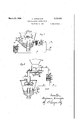
Fig. 1 is a sectional elevation of an impact comminuting device with a tongue to control the charging of the device.
Fig. 2 is a sectional elevation of an impact 20 comminuting device with a disc feeder.
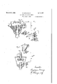
Fig. 3 is a sectional elevation of an impact comminuting device with an adjustably controlled mixing tube.
Fig. 4 is a sectional elevation of an impact 25 comminuting device with means to control the inflow by pneumatic means.
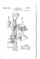
Fig. 5 is a sectional elevation of an impact comminuting device with a chain feeding device to adjust the rate of flow of the material to the 30 pulverizers.
Fig. 5a is a detail view hereinafter referred to.
All the different figures have in common the following references: I denotes the expansion nozzle for the compressed air, 2 the mixing tube, 35 3 an impact body, 4 the sifting blades, 5 a funnel,
6 a conical body, I the outflow socket for the air and the finely comminuted material, 8 the inflow socket or the chute for the inflowing raw material.
The comminuting device works as follows:
The compressed air or gas or vapour expanded in the nozzle l engages the material to be comminuted and projects the same through the mixing tube against the impact body 3.- The com- 45 minuting is attained by impact and by relative friction of the particles. By means of the blades 4 inclined to the radius a rotation is set up which causes the coarse materialto flow back to the raw material. A second division is effected in the 5 space between the parts 5 and 6. Material rejected there flows through the slots 9 back into the first sifting chamber. The produced dust passes together with the .air through the socket 1-. In. the device shown in Fig. 3 part of the air 55 jet takes with it mainly rejected material and the other part mainly raw material. In all other devices a mixture of raw material and of rejected material is worked on.
In all the figures l0 denotes a body having a shaft and blades fixed thereon. The body is arranged at or near the level of the charge which is to be maintained. The shaft is connected with a motor. ll driving a pair of toothed gears I2, l2 (Fig. 1 shows the motor in sectional elevation and in a cross section). l3 and I4 denote the conduits for the driving fluid of the motor II. In Figs. 1 to 3, l5 indicates a throttling device arranged in the conduit I3. 80 denotes a pressure gauge. adapted to measure the pressure of the fluid driving the motor ll.
In the device shown in Fig. 1 the pipe I3 is connected with the space below the piston l8 of cylinder IT. The piston I8 is loaded by a spring l9 abutting on a cover 20. To the piston rod 2| a lever 221s linked which is keyed on a shaft 23. On the said shaft 23 a tongue'24 is fastened. As long as the body It) is not immersed in the material, its rotation offers no resistance. The motor ll runs at great speed, it offers no appreciable resistance to the flow of the driving medium (which may be a gas or a liquid). The pressure in the pipe I3 is low, the piston I8 is down and the inflow socket 8 is open. If the level of the material rises resistance is offered to the rotation of the body l0 and the motor ll.
-'I'he pressure in the pipe l3 raises, the piston I8 is moved upwardly-and closes the inflow 8. The pressure gauge 80 indicates the condition within the pulverizer. I
In the device shown in Fig. 2 the material is fed to the comminuting apparatus from the bunker 3|) by means of a disk feeding device. The
said feeding device comprises a casing 3|, a disc 32 and a retaining rod 35. The disc 32 is driven by a motor (not shown in thedrawings) by means of a worm 33 and a worm wheel 34. Between the outflow of the bunker and. the disc feeder a tube 29 is arranged. The tube 29 is provided with pivots 21. A fork 28 engaging said pivots 21 is rotatably mounted at 26. An arm 25 of the fork 28 is linked to the piston rod 2l of the piston 20. The piston 20 works as described with reference to the device shown in Fig. 1. If the level of the material rises above the body I an increased resistance is offered to the motor II, the pressure of the driving medium is increased. -The piston It! moves upwardly and the pipe 29 is moved downwardly. The amount of the material fed to the disc 32 is reduced accordingly.
In the comminuting device illustrated in Fig. 3 the pipe I3 is connected by a pipe Hi to a chamber 40, closed by bellows 4|. The bellows 4| are loaded by a spring 42 abutting on a cover 43. A rod 44 is connected with the said bellows and to a piston-slide 45, 46 in the distributing chamber 41. The chamber 41 is provided with an inflow 48 and two outflows 49, 50 of the driving medium. Pipes 5|, 52 connect the outflow openings 49, 50 with the motor 53 which may be for instance a toothed gear pump. The motor 53 drives by means of a spur wheel 54 a toothed gear 55, running in ball bearings 56, 51, the boss of which forms a nut for a screw-threaded spindle 58. The spindle 58 is provided with cross pins 59 engaging a fork 60 of a two-armed lever 6| rotatably mounted at 62. The bifurcated end I! of lever ii engages'cross pins 64 of a mixing tube 2 which is slidably mounted in the device,
I fro movement.
The mixing tube 2 is co-axially arranged above the expansion nozzle and is movable in axial direction. If the level of the material within the device rises increased resistance is offered to the motor II as described above. The pressure of the driving medium is increased at It. The bellows 4| are compressed, the piston slide 45, 46 is lifted. The parts 49, 50 are opened and the driving medium passes to the motor 53. The motor 53 shifts the tube 2 downwardly, the flow of raw material to the comminuting device is retarded.
Fig. 4 illustrates an impact comminuting device in connection with a bunker of raw mate rial of which bunker but the lower part 10 is shown. The said bunker is provided with movable wall pieces H, l2, 13, having projections to facilitate the downward flow of the raw material and to prevent the chocking of the channel.
Such auxiliary devices are especially necessary 5 when finely pulverized raw material in a moist condition (moist coal dust) is to be fed. At the lower end of the bunker a nozzle-shaped gap 14 is arranged, the bottom wall 18 forms the tangential continuation of the said gap. A chamber 15 is located in advance of the said gap. The said chamber 15 is connected to the outflow of the motor II by a pipe l4: Compressed air is used to drive the motor. While the level of the material within the-comminuting device is low a greatamount of air flows through the nozzle I4 and a great quantity of raw material is blown into the pipe 8. If the speed of the motor ll decreases according to the height of the level of raw material less air flows through the nozzle 14 and correspondingly less raw material is fed into the comminuting device. The bottom 18 may be inclined, moreover the wall 11 may be made slanting in such a manner that the material fed cannot adhere on the walls 11, 18 and falls by its own weight. any suitable material may be used for said walls TI, 18 on which the material cannot adhere. In place of air and of the injection of air directly by the motor I I as described any other injection device for raw material may be used, which device would have to be controlled in the manner and by the means aforesaid.
It may be pointed out that in the shape andthe arrangement of the body l0 there is no restrictio-n the same may be said about the motor I i and the movement of the body l0 performs. The body l0 may perform for instance a to and. The means for signalling may be of any known kind, for instance pressure gauges in combination with electrical signalling devices giving acoustic or optical signals. If a liquid or gaseous driving medium is used a valve or the like may be arranged behind the motor II, and the impulse to act on the signalling and controlling devices may be derived from a point behind the motor. If as a motor ii an electric motor is used appropriate controlling means are to be used, such as electrical or magnetical auxiliary devices. The motor ll may be brought in the circuit of an electric motor driving a feeding Moreoverrods II8 are fixed. The chain runs over rollers 85,- 88, 81. One of the rollers is drivlngly connected to a motor not shown in the drawings. The chain runs in the direction of the arrows I88, I89. The chain feeding device is shown in connection with two impact comminuting devices of known construction. The partition wall 83 is provided with two openings 88, 89. The material to be fed to the comminuting device flows through the said openings 88. 89 from the upper part of thetrough into the lower part thereof. The lower run of the chain catches the material and moves the same to the openings 93, 94 in the lower part 84 of the trough. The material falls through the said openings into the comminuting device. In front of each of the openings 99, 94 a rotary slide 9| is rotatably mounted on the shaft 92. According to the position of the slide more or less material is fed by the chain to the openings 93, 94. The slides are set by the shaft 92 in dependance to the position of the level of the ma-- terial in the comminuting device. To the shaft 92 an arm 22 is rigidly fixed which is connected.
by the link 22 to the piston I8 of a servo-motor constructed and working as described above. The
space beneath the piston I8 is connected with the outflow pipe for the motive fluid which drives the motor II. The throttle I isarranged in the outflow I4 and not as described above with reference to the examples shown in Figs. 1 to 4, into the inflow pipe I3. As long as the body I8 flnds no resistance by the charge fed into the comminuting device the motor II runs rapidly and a great amountof motive fluid passes through said motor. The pressure in the space beneath the piston I8 is high and reacts against the action of the spring I9.
The pressure tends to open the slide 9|. If however the body I8 is partly or wholly covered by the material its rotation finds increased resistance. The speed of the motor II slows down. The amount of motive fluid passing through the motor decreases. The pressure below the piston I8 decreases accordingly. The slide 9| is now.
moved in a position to restrict the feed of the material. The arrangement of the throttle I5 in the outflow pipe of the motive fluid has the advantage that in case that the flow of motive fluid ceases, the slide 9I closes entirely. If for instance compressed air is used as a motive fluid and is tapped in front of the nozzle I,the feed of material ceases entirely as soon as the flow .of the compressed air ceases.
If the feeding device feeds material in excess to that flowing tothe openings 93, 94 there is left at 89 an excess ofmaterial which is fed by the chain and which falls over the edge 98 into i the lower part of the trough. That surplus material would fill up the whole lower half of the trough at the-right of the opening 94, and finally the upper half of the trough would be filled with surplus material too. The chain would have to pass through the material without feeding the same and the wear of the chain would increase.
:- If the material is of granular and moisty nature the material would stick fast. A regular flow of material from the upper half of the trough into the lower half at 88 and 89 would be quite uncertain. Sucha condition is to be obviated and I attainthis by the following means:
In the space ofthe lower half of the trough between the edge 98 and the opening 89 the body I8a is arranged, whichis moved by the motor Ila (Fig. 5a). The body Illa is driven by an electric motor. Into the circuit of the motor bematerial.
tween the points I88 and I82 a solenoid IN is arranged. The solenoid is provided with a core I83. The core stands under the action of the spring I84 and is linked to the lever I85. The lever I88 is rigidly fixed to the shaft of the slide 9Ia. By the slide 9Ia the material passing from the bunker on to the chain may be controlled. If the material accumulates in the lower half of the trough and comes in the reach of the body I8a the movement of the latter is braked. The current in the circuit of the motor Ila increases. The solenoid attracts the core. The latter moves to the left (Fig. 5a). The slide 9Ia. is moved in such a manner as to close the outflow opening of the bunker 8|. On the contrary if less material passes from the bunker 8I on the chain, as may flow through the openings 93, 94 the body I8a will be freed from material. The resistance offered to the rotation of the body I8a. diminishes, the current in the circuit decreases correspo-ndingly and also the power of the solenoid. The spring I84 moves now the core to the right and the slide 9| is opened. To drive the body 18a, the same or a similar motor as denoted by II may be used and therewith a liquid or gaseous motive fluid; in such a case a suitable servo-motor has to be used to operate the slide 9Ia.
If by the chain feeding device but one comminuting device is to be served, only one slide 9Ia has to be operated to adjust the amount of material fed. The device I8a is in such a case not needed at all.
The slide 9Ia is operated by the device I8 according to the level of the charge in the comminuting device.
Chain feeding devices are especially useful in connection with the feed of very fine and of moist bunkers great difilculties as the flow of material from the bunker very frequently chocks. The receiving portion of such a chain feeding device according to my invention may be long and the formation of bridges of moist material above the outflow portion of the bunkers may thereby be prevented. The chain feeding devices moreover allow the arrangement of the comminuting device at great distances from the bunker. The chain feeding devices allow the location of the comminuting devices in any convenient place. If the openings 88, 89 and the openings 99, 94 are long enough the failing of the flow of material through the said openings can always be obviated.
The chain feeding device allows therefore the feeding of very fine and moist material, or material which offers the very greatest difflculties to feeding by the known devices.
What I claim and wish to secure by U. S. Letters Patent is:
1. In apparatus of the character stated wherein is provided a container, means to flow material into the container, means to remove material from the container, a body, a fluid actuated motor connected with said body for imparting continuous motion to said body. said body being so positioned in the'container that when the level of the material in the container rises above the normal level it will engage said body and thereby apply a braking action to said moving body and said motor, and consequently a variation in the power fluid flowing through said motor is effected, and means utilizing the variation of said power fluid to control the flow of material through the container, said body and its actuating motor being independent of said means to flow Such material offers in the usual and remove material into and from the container.
' 2. In apparatus of the character stated wherein is provided a container, means to flow material into the container, means to remove material from the container, a body, a fluid actuated motor connected with said body for imparting continuous motion to said body, said body being so positioned in the container that when the level of the material in the container rises above the normal level it will engage said body and thereby apply a braking action to said moving body and said motor, and consequently a variation in the power fluid flowing through said motor is eifected, and means utilizing the variation of said power fluid to signal the state of the contents of the container, said body and its actuating motor being independent of said means to flow and remove material into and from the container.
3. In apparatus of the character stated wherein is provided a container, means to flow material into the container, means to remove material from the container, a body, a fluid actuated motor connected with said body for imparting continuous motion to said body, said body being so positioned in the container that when the level of the material in the container rises above the normal level it will engage said body and thereby apply a braking action to said moving body and said motor, and consequently a variation in the power fluid flowing through said motor is effected, means utilizing the variation of said power fluid to control the flow of material through the container and signal the state of the contents of the container, said body and its actuating motor being independent of said means to flow and remove material into and from the container.
4. In apparatus of the character stated wherein is provided a container, means to remove material from the container, a fluid actuated motor, a body driven by said motor located within said container for cooperation with the material therein and governed by the resistance oilered to the movements of said body by the material within the container, means for controlling the flow of material through said container governed by the variations of the motor activating fluid of the said motor, and means to signalize the amount of material in the container, saidbody and its actuating motor being independent of said means to flow and remove material into and from the container.
BENJAMIN GRAEMIGER.
Applications Claiming Priority (1)
| Application Number | Priority Date | Filing Date | Title |
|---|---|---|---|
| DE2111663X | 1934-06-11 |
Publications (1)
| Publication Number | Publication Date |
|---|---|
| US2111663A true US2111663A (en) | 1938-03-22 |
Family
ID=7985464
Family Applications (1)
| Application Number | Title | Priority Date | Filing Date |
|---|---|---|---|
| US24836A Expired - Lifetime US2111663A (en) | 1934-06-11 | 1935-06-04 | Feed regulator control means |
Country Status (1)
| Country | Link |
|---|---|
| US (1) | US2111663A (en) |
Cited By (32)
| Publication number | Priority date | Publication date | Assignee | Title |
|---|---|---|---|---|
| US2418547A (en) * | 1943-03-17 | 1947-04-08 | Cowles Co | Method and apparatus for defibering paper stock |
| US2433560A (en) * | 1944-10-30 | 1947-12-30 | Jr Samuel C Hurley | Hopper controller for uniformly feeding unit articles |
| US2533986A (en) * | 1944-09-22 | 1950-12-12 | Precast Building Sections Inc | Apparatus and method for filling molds |
| US2559557A (en) * | 1944-07-12 | 1951-07-03 | Babcock & Wilcox Co | Aerating feeding of pulverized materials |
| US2624516A (en) * | 1949-01-04 | 1953-01-06 | Blaw Knox Co | Fluid impact pulverizer and separator |
| US2638385A (en) * | 1943-10-20 | 1953-05-12 | Smidth & Co As F L | Conveying apparatus |
| US2652984A (en) * | 1949-05-05 | 1953-09-22 | Safety Car Heating & Lighting | Flow control apparatus for bulk products |
| US2672296A (en) * | 1949-01-04 | 1954-03-16 | Blaw Knox Co | Fluid impact pulverizer |
| US2681131A (en) * | 1950-06-28 | 1954-06-15 | Standard Oil Co | Coal-feeder stoppage indicator |
| US2687817A (en) * | 1952-02-01 | 1954-08-31 | Chesapeake & Ohio Railway | Method and apparatus for controlling the flow of solid materials |
| US2737997A (en) * | 1953-12-01 | 1956-03-13 | Allwood Inc | Apparatus for producing uniform mats of pourable particle material |
| US2788922A (en) * | 1954-02-06 | 1957-04-16 | Buehler Ag Geb | Device for mixing and discharging bulk materials |
| US2795313A (en) * | 1954-02-08 | 1957-06-11 | James Mfg Co | Means for moving feed forward in a reciprocating feed trough |
| US3244325A (en) * | 1964-01-16 | 1966-04-05 | Oxy Dry Sprayer Corp | Apparatus for applying a film of powder |
| US3338434A (en) * | 1965-02-25 | 1967-08-29 | Melvin W Kolze | Sweep arm bin unloader |
| US3348886A (en) * | 1966-03-04 | 1967-10-24 | Hergeth Kg Masch Apparate | Feeding devices for fiber treating machines |
| US3357576A (en) * | 1965-08-26 | 1967-12-12 | Carl E Strombeck | Apparatus for loading and transporting particulate material |
| US3376202A (en) * | 1964-10-08 | 1968-04-02 | Pacific Scientific Co | Waste converter |
| US3405820A (en) * | 1966-04-21 | 1968-10-15 | Ishikawajima Harima Heavy Ind | Dust-proof hopper |
| US3412877A (en) * | 1966-04-08 | 1968-11-26 | Bin Dicator Company | Electrical-optical material level control |
| US3414142A (en) * | 1967-05-09 | 1968-12-03 | Melvin W. Kolze | Sweep arm bin unloader |
| US3501052A (en) * | 1967-02-20 | 1970-03-17 | Hauni Werke Koerber & Co Kg | Magazine for cigarettes or the like |
| US3777874A (en) * | 1971-12-22 | 1973-12-11 | Air Prod & Chem | Powder deposition system |
| US3866799A (en) * | 1973-06-18 | 1975-02-18 | Nat Eng Co | Mixer with automatically controlled discharge system |
| US3920155A (en) * | 1973-05-07 | 1975-11-18 | Xerox Corp | Particle level indicator |
| US3946901A (en) * | 1973-04-04 | 1976-03-30 | Gebruder Buhler Ag | Apparatus for controlling the level of a particulate pourable material in a defined space |
| US3968626A (en) * | 1974-11-11 | 1976-07-13 | Hobbs Oliver K | Apparatus for bagging material |
| US4496084A (en) * | 1982-09-22 | 1985-01-29 | Sam Stein Associates, Inc. | Breading machine |
| US4798283A (en) * | 1982-09-22 | 1989-01-17 | Stein Associates, Inc. | Breading machine |
| US5242122A (en) * | 1991-03-25 | 1993-09-07 | Sala International Ab | Method and arrangement for finely grinding minerals for use as fillers |
| US5361996A (en) * | 1991-12-20 | 1994-11-08 | Sala International Ab | Method and arrangement for finely-grinding minerals |
| US5555967A (en) * | 1995-01-23 | 1996-09-17 | Key Technology, Inc. | Vibratory distributor for bulk articles |
-
1935
- 1935-06-04 US US24836A patent/US2111663A/en not_active Expired - Lifetime
Cited By (32)
| Publication number | Priority date | Publication date | Assignee | Title |
|---|---|---|---|---|
| US2418547A (en) * | 1943-03-17 | 1947-04-08 | Cowles Co | Method and apparatus for defibering paper stock |
| US2638385A (en) * | 1943-10-20 | 1953-05-12 | Smidth & Co As F L | Conveying apparatus |
| US2559557A (en) * | 1944-07-12 | 1951-07-03 | Babcock & Wilcox Co | Aerating feeding of pulverized materials |
| US2533986A (en) * | 1944-09-22 | 1950-12-12 | Precast Building Sections Inc | Apparatus and method for filling molds |
| US2433560A (en) * | 1944-10-30 | 1947-12-30 | Jr Samuel C Hurley | Hopper controller for uniformly feeding unit articles |
| US2624516A (en) * | 1949-01-04 | 1953-01-06 | Blaw Knox Co | Fluid impact pulverizer and separator |
| US2672296A (en) * | 1949-01-04 | 1954-03-16 | Blaw Knox Co | Fluid impact pulverizer |
| US2652984A (en) * | 1949-05-05 | 1953-09-22 | Safety Car Heating & Lighting | Flow control apparatus for bulk products |
| US2681131A (en) * | 1950-06-28 | 1954-06-15 | Standard Oil Co | Coal-feeder stoppage indicator |
| US2687817A (en) * | 1952-02-01 | 1954-08-31 | Chesapeake & Ohio Railway | Method and apparatus for controlling the flow of solid materials |
| US2737997A (en) * | 1953-12-01 | 1956-03-13 | Allwood Inc | Apparatus for producing uniform mats of pourable particle material |
| US2788922A (en) * | 1954-02-06 | 1957-04-16 | Buehler Ag Geb | Device for mixing and discharging bulk materials |
| US2795313A (en) * | 1954-02-08 | 1957-06-11 | James Mfg Co | Means for moving feed forward in a reciprocating feed trough |
| US3244325A (en) * | 1964-01-16 | 1966-04-05 | Oxy Dry Sprayer Corp | Apparatus for applying a film of powder |
| US3376202A (en) * | 1964-10-08 | 1968-04-02 | Pacific Scientific Co | Waste converter |
| US3338434A (en) * | 1965-02-25 | 1967-08-29 | Melvin W Kolze | Sweep arm bin unloader |
| US3357576A (en) * | 1965-08-26 | 1967-12-12 | Carl E Strombeck | Apparatus for loading and transporting particulate material |
| US3348886A (en) * | 1966-03-04 | 1967-10-24 | Hergeth Kg Masch Apparate | Feeding devices for fiber treating machines |
| US3412877A (en) * | 1966-04-08 | 1968-11-26 | Bin Dicator Company | Electrical-optical material level control |
| US3405820A (en) * | 1966-04-21 | 1968-10-15 | Ishikawajima Harima Heavy Ind | Dust-proof hopper |
| US3501052A (en) * | 1967-02-20 | 1970-03-17 | Hauni Werke Koerber & Co Kg | Magazine for cigarettes or the like |
| US3414142A (en) * | 1967-05-09 | 1968-12-03 | Melvin W. Kolze | Sweep arm bin unloader |
| US3777874A (en) * | 1971-12-22 | 1973-12-11 | Air Prod & Chem | Powder deposition system |
| US3946901A (en) * | 1973-04-04 | 1976-03-30 | Gebruder Buhler Ag | Apparatus for controlling the level of a particulate pourable material in a defined space |
| US3920155A (en) * | 1973-05-07 | 1975-11-18 | Xerox Corp | Particle level indicator |
| US3866799A (en) * | 1973-06-18 | 1975-02-18 | Nat Eng Co | Mixer with automatically controlled discharge system |
| US3968626A (en) * | 1974-11-11 | 1976-07-13 | Hobbs Oliver K | Apparatus for bagging material |
| US4496084A (en) * | 1982-09-22 | 1985-01-29 | Sam Stein Associates, Inc. | Breading machine |
| US4798283A (en) * | 1982-09-22 | 1989-01-17 | Stein Associates, Inc. | Breading machine |
| US5242122A (en) * | 1991-03-25 | 1993-09-07 | Sala International Ab | Method and arrangement for finely grinding minerals for use as fillers |
| US5361996A (en) * | 1991-12-20 | 1994-11-08 | Sala International Ab | Method and arrangement for finely-grinding minerals |
| US5555967A (en) * | 1995-01-23 | 1996-09-17 | Key Technology, Inc. | Vibratory distributor for bulk articles |
Similar Documents
| Publication | Publication Date | Title |
|---|---|---|
| US2111663A (en) | Feed regulator control means | |
| US3406426A (en) | Apparatus for forming aggregates of powdered materials | |
| US4572441A (en) | Pneumatic control system for grinding mill | |
| GB982387A (en) | Volumetric feeder device | |
| US2367278A (en) | Sugar-cane feeder | |
| US2273296A (en) | Apparatus and process for separat | |
| US3690570A (en) | Method of and system for controlling grinding mills | |
| US2100848A (en) | Feeder control mechanism | |
| GB390257A (en) | Improvements in or relating to the conveyance and mixing of granular materials such as concrete or the like | |
| US1611675A (en) | Scalper and cut-off attachment for feed mills | |
| GB1093111A (en) | Improvements in apparatus for delivering divided material | |
| US1941573A (en) | Conveying system | |
| US2057768A (en) | Feed valve | |
| US1463094A (en) | Manufacture of briquettes | |
| US922085A (en) | Measuring apparatus. | |
| US2291618A (en) | Pulverizing apparatus | |
| GB403936A (en) | Improvements in flow controlling devices | |
| US1849871A (en) | Pulverizing mill and the like | |
| US2001331A (en) | Process and mechanism for separating intermixed divided materials | |
| US2318306A (en) | Feed system for grinding mills | |
| CN214819378U (en) | Distributor for shaving board | |
| GB1055795A (en) | Improvements in means for continuously feeding pulverulent or granular materials | |
| US1900347A (en) | Coal briquetting equipment | |
| US2031116A (en) | Safety outlet closure for conveyers | |
| SU84708A1 (en) | Dosing hopper for molding and core sands |