US2228811A - Discharge apparatus for washing water closets - Google Patents
Discharge apparatus for washing water closets Download PDFInfo
- Publication number
- US2228811A US2228811A US281986A US28198639A US2228811A US 2228811 A US2228811 A US 2228811A US 281986 A US281986 A US 281986A US 28198639 A US28198639 A US 28198639A US 2228811 A US2228811 A US 2228811A
- Authority
- US
- United States
- Prior art keywords
- lever
- reservoir
- water
- packing
- obturator
- Prior art date
- Legal status (The legal status is an assumption and is not a legal conclusion. Google has not performed a legal analysis and makes no representation as to the accuracy of the status listed.)
- Expired - Lifetime
Links
Images

Classifications
-
- E—FIXED CONSTRUCTIONS
- E03—WATER SUPPLY; SEWERAGE
- E03D—WATER-CLOSETS OR URINALS WITH FLUSHING DEVICES; FLUSHING VALVES THEREFOR
- E03D1/00—Water flushing devices with cisterns ; Setting up a range of flushing devices or water-closets; Combinations of several flushing devices
- E03D1/30—Valves for high or low level cisterns; Their arrangement ; Flushing mechanisms in the cistern, optionally with provisions for a pre-or a post- flushing and for cutting off the flushing mechanism in case of leakage
- E03D1/304—Valves for high or low level cisterns; Their arrangement ; Flushing mechanisms in the cistern, optionally with provisions for a pre-or a post- flushing and for cutting off the flushing mechanism in case of leakage with valves with own buoyancy
Landscapes
- Health & Medical Sciences (AREA)
- Life Sciences & Earth Sciences (AREA)
- Engineering & Computer Science (AREA)
- Hydrology & Water Resources (AREA)
- Public Health (AREA)
- Water Supply & Treatment (AREA)
- Float Valves (AREA)
- Sanitary Device For Flush Toilet (AREA)
Description
Jan. 14, 1941. Q BEUTlN 2,228,811
DISCHARGE APPARATUS FOR WASHING WATER OLOSETS Filed June 29, 1939 2 Sheets-Sheet l Jan. 14, 1941; -m 2,228,811
DISCHARGE APPARATUS FOR WASHING- WATER CLOSETS Filed June 29, 1939 2 Sheets-Sheet Z Patented Jan. 14, 1941 UNITED STATES PATENT OFFICE DISCHARGE APPARATUS FOR WASHING I WATER. CLOSETS 3 Claims.
This application relates to a new water discharge apparatus :for Washing water closets, which, due to the special features thereof and the results obtained in testing same, oifer important advantages over all types of devices known and used heretofore for the same purpose.
The mechanism of the novel apparatus subject of the present invention may be said to constitute a single element so arranged that, without requiring auxiliary intermediary means, it reflects the external action inwardly, and the corresponding displacement does not cause disturbances in the point of admission to the reservoir. Also, it is possible to keep the apparatus water-tight by means of a simple packing, thus avoiding water leakage and insuring the perfect operation of the apparatus.
For this purpose, the apparatus subject of the present invention, comprising a reservoir having its discharge pipe closed by a float obturator, is provided with an actuating element constituted by a lever arranged so that the power arm thereof is located outside the reservoir so as to be manually operated, while the resistance arm of said lever is located within the reservoir for connection with the float obturator. Thus, the fulcrum of said lever is on the wall of the reservoir itself, that is to say, the dead point of the lever, where there it has practically no movement, is on the 30 reservoir wall. This makes it possible to readily render the opening for the passage of the lever water-tight and to keep same sealed, through any suitable packing or the like.
The invention also provides a simple way for combining the means for assembling the actuating mechanism. This onlyrequires a simple set of wedges or the like, so that the fulcrum of the lever will lie on the edge of the opening in the wall, and a packing is adapted on the fulcrum.
40 The tightening of said packing will be suiiicient to render the opening water-tight, as at said dead point of the lever there is no substantial movement involved. Also there is the additional advantage that there is no resistance and therefore the mechanism is light and may be actuated by means of a button or directly through the power In order that the invention may be more clearly understood and readily carried into practice, same has been illustrated by way of example and in a preferred embodiment in the accompanying drawings, wherein:
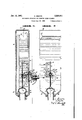
Figure 1 is a side sectional view of the apparatus, showing the simple mechanism constituted by the lever having its power lever located outside the reservoir and its resistance arm within said reservoir, so that the dead point is located exactly on the apertured wall thereof provided with a corresponding packing. In this figure, the full lines show the mechanism in inoperative 5 position, while the dotted lines show same in operative position for discharging the water.
Figure 2 is a rear sectional view of the apparatus, showing the manner in which the resistance arm enters the reservoir for connection with the 10 obturator rod. This rod is guidedly mounted by means of a simple screw adapted from the outside and made water-tight by means of the same packing as used for the lever.
Figure 3 is a front view showing the box of the control button which is preferably connected to the power arm of the lever; and
Figure 4 is a plan view of the apparatus, showing the fulcrum on the reservoir wall, with the corresponding sealing packing; said fulcrum is not subject to movement as it is located on the dead point of the lever.
The same reference characters indicate like or corresponding parts or elements throughout the different views.
With reference to the drawings, a is the reservoir to which water is supplied through pipe I as admitted by valve 2, controlled float-valve 3, the latter being arranged so as to close said floatvalve upon the water reaching a certain fullcharge level in the reservoir.
As is common in apparatus of this type, the bottom of the reservoir a has an outlet provided with a seat 4 corresponding to the starting point of the discharge pipe 5 leading to the watercloset. .An obturator 6 is seated on said seat 4, said obturator being floatable since it is made lighter than water, and in order to provide an effective closure, said obturator 6 is open at the bottom. The upper portion of said obturator is joined to a rod 1 guided in two points of a guide 8, the latter forming a single unit and being adapted against the front wall 9 of reservoir a, where said guide 8, fitted between buttons II], is secured by means of a screw I I passing through said Well 9 so as to be movable from the outside of the reservoir.
As the obturator 6' must be raised to cause the discharge of the water contained in the reservoir, this is done through a lever b, the novel structure 50 and arrangement of which constitute the basis of the present invention. This lever has its fulcrum l2 on the wall 9 of reservoir a, with the particularity that as it passes through an opening in said wall, this lever b, which is of the first class, 55
has its power arm I3 on the outside of the wall 9, while the resistance arm I4 thereof operates in the interior of the reservoir, as clearly shown in Figures 1, 2 and 4.
The opening through which the lever 1) passes is indicated at I5, and as may be seen in the drawings near said opening are the hearings or other suitable means forming, together with a shaft l2, the fulcrum I2 of said lever. As the lever b passes into the reservoir at a point near the obturator 6, in order to avoid leakage of water said opening I5 is provided with a packing I6 of rubber or other suitable material, adapted over the fulcrum I2 so as to serve as a joint on the dead point of the lever. A mere tightening of said packing will be sufiicient to provide a watertight seal, as the lever at that point has practically no movement capable of disturbing the seal, and also for this reason the packing will not affect the action of the lever, which is light due to the little resistance offered thereby.
The free end of the resistance arm I4 of lever b is provided with a fork surrounding rod I and coinciding with a stop I, so that upon actuating the lever b (as clearly shown in Figure 1) said arm will act against stop 1 and cause the lifting of obturator 6 and the latter, after leaving the seat 4 thereof, will float to the position indicated in dotted lines in Figure 1.
The externally located power arm I3 of the lever is connected to the stem of button H which, acting'in a box or body I8 and pressed by a spring I9, constitutes the manual control or actuating element 0. As may be seen from the drawings, said box or body I8 extends forming a casing 20 flanged so as to be adapted against the packing I6, and the latter extends so as to serve as a joint and seat for the entire mount of the device 0.
Said casing ZD'encloses the power arm I3 of lever b and provides sufficient space to enable the displacement of said arm upon being actuated by button I1, for the purpose of raising the obturator through the resistance arm of lever b, as described above.
As shown in Figures 3 and 4, said casing 20, acting as a socket for the device c, is secured to wall 9 of reservoir a by means of screws, in such a manner that said casing presses said packing I6 so as to obtain a water-tight seal.
As shown in Figure 2, screw I I engaging guide 8, has the head thereof outside of the reservoir but is screwed until level with the outer surface of the reservoir wall, in such a manner that the same packing I6 will also seal the orifice through which said screw II is passed. Therefore, packing I6 seals the entire control or actuating mechanism as a unit.
Due to the fact that the only actuating element is constituted by the lever b, the operation of the apparatus above-described is very simple. Upon moving said lever, through the control but ton H, from the position shown in full lines in Figure 1, same is displaced to the position shown in dotted lines, thereby causing the resistance arm of lever 11 to act against stop I of rod I and lifting obturator 6 sufficiently to make the latter leave the seat 4 and move upwardly by flotation to the position shown in dotted lines, thus allowing the discharge of the water contained in the reservoir.
After the discharge of water has been completed, upon releasing the button I! the latter will return to the position shown in full lines by virtue of spring I9, and due to the weight of obturator 6 returning to the seat 4, or through the action of a weight or spring, lever 17 will return to the position shown in full lines, ready to cause a further discharge of water after the latter has again filled the reservoir up to the corresponding level.
From the above, it may be seen that the main feature of the apparatus subject of the present invention is the lever b which does away with the necessity of an elaborate transmission, as by arranging said lever with the power arm located outside of the reservoir and the resistance arm within same, it received and produces in a direct manner the effect necessary to actuate the obturator 6, without affecting the water-tight joint formed, as stated above, by a packing on the fulcrum equivalent to the dead point of lever b. Instead of the button H, the control may comprise a crank formed with the power arm I3 itself.
It is evident that several changes in construction and detail may be carried out by those skilled in the art without departing from the scope of the present invention as clearly set forth in the appended claims.
What I claim is:
1. A water discharge apparatus for flushing water closets comprising a reservoir having a discharge outlet, a guided float obturator in said reservoir for closing said discharge outlet, a control element for actuating said float obturator, said reservoir being provided with an opening in the front wall thereof, a resilient packing member constituting a sealing closure for said opening, said packing member being provided with a passageway therethrough, an angular lever extendl ing through said passageway in sealed relationship to said packing member, means for pivotally journalling said lever at said passageway, said angular lever being so constructed and arranged as to provide a power arm and a resistance arm, said power arm being externally located relative to said reservoir and defining an acute angle with the plane of the front wall of the latter, said control element being mounted on said front wall and being substantially perpendicularly dis- 5.
posed relative to the latter, said power arm being operatively connected to said control elements, and said resistance arm being internally located relative to the reservoir and being operatively connected to said obturator.
2. A water discharge apparatus as defined in claim 1, casing means on said front wall providing a guiding support for said control element. and said packing simultaneously constituting sealing means for said casing means.
3. A water discharge apparatus as defined in claim 1, casing means on said front wall providing a guiding support for said control element, said packing simultaneously constituting sealing means for said casing means, and means for normally urging said control element away from said power arm, said power arm being forked at its inner end.
CARLOS BEUTIN.
Cal
Priority Applications (1)
| Application Number | Priority Date | Filing Date | Title |
|---|---|---|---|
| US281986A US2228811A (en) | 1939-06-29 | 1939-06-29 | Discharge apparatus for washing water closets |
Applications Claiming Priority (1)
| Application Number | Priority Date | Filing Date | Title |
|---|---|---|---|
| US281986A US2228811A (en) | 1939-06-29 | 1939-06-29 | Discharge apparatus for washing water closets |
Publications (1)
| Publication Number | Publication Date |
|---|---|
| US2228811A true US2228811A (en) | 1941-01-14 |
Family
ID=23079605
Family Applications (1)
| Application Number | Title | Priority Date | Filing Date |
|---|---|---|---|
| US281986A Expired - Lifetime US2228811A (en) | 1939-06-29 | 1939-06-29 | Discharge apparatus for washing water closets |
Country Status (1)
| Country | Link |
|---|---|
| US (1) | US2228811A (en) |
Cited By (4)
| Publication number | Priority date | Publication date | Assignee | Title |
|---|---|---|---|---|
| US2504555A (en) * | 1948-02-26 | 1950-04-18 | Raymond H Loether | Flush valve |
| US2608207A (en) * | 1947-01-15 | 1952-08-26 | American Machine & Metals | Sealed float rod |
| US2959980A (en) * | 1957-11-27 | 1960-11-15 | Sloan Valve Co | Flush valve operator |
| US3148381A (en) * | 1960-11-30 | 1964-09-15 | Morales Juan Alberto | Water closet tank and outlet valve |
-
1939
- 1939-06-29 US US281986A patent/US2228811A/en not_active Expired - Lifetime
Cited By (4)
| Publication number | Priority date | Publication date | Assignee | Title |
|---|---|---|---|---|
| US2608207A (en) * | 1947-01-15 | 1952-08-26 | American Machine & Metals | Sealed float rod |
| US2504555A (en) * | 1948-02-26 | 1950-04-18 | Raymond H Loether | Flush valve |
| US2959980A (en) * | 1957-11-27 | 1960-11-15 | Sloan Valve Co | Flush valve operator |
| US3148381A (en) * | 1960-11-30 | 1964-09-15 | Morales Juan Alberto | Water closet tank and outlet valve |
Similar Documents
| Publication | Publication Date | Title |
|---|---|---|
| US2835900A (en) | Operating mechanism for toilet flush tank valve | |
| US2228811A (en) | Discharge apparatus for washing water closets | |
| US2799290A (en) | Flush tank valve | |
| US2190160A (en) | Flushing mechanism for toilet tanks | |
| US2361225A (en) | Line pressure opened self-closing valve | |
| US3082785A (en) | Automatic shut-off valve | |
| US3102711A (en) | Flush valves | |
| US2996727A (en) | Positive closing toilet tank valve | |
| US2367951A (en) | Ball cock | |
| US2692609A (en) | Fueling system | |
| US3348242A (en) | Water closet device | |
| US2849725A (en) | Flushing valves for cisterns | |
| US2296219A (en) | Snap action float valve | |
| US1416317A (en) | Flush valve | |
| US2781519A (en) | Flushing system | |
| US3060450A (en) | Water flushing system | |
| US3026535A (en) | Double tank flushing apparatus | |
| US2412452A (en) | Flush tank control | |
| US2083486A (en) | Flush valve | |
| US2681661A (en) | Valve | |
| US2321631A (en) | Fluid pressure controlling apparatus | |
| US2786493A (en) | Hose nozzle of the automatic shut-off type | |
| US2014483A (en) | Flush valve | |
| US1521354A (en) | Flush valve | |
| US1081110A (en) | Flushing device. |