US2344686A - Paper drier and method - Google Patents
Paper drier and method Download PDFInfo
- Publication number
- US2344686A US2344686A US400286A US40028641A US2344686A US 2344686 A US2344686 A US 2344686A US 400286 A US400286 A US 400286A US 40028641 A US40028641 A US 40028641A US 2344686 A US2344686 A US 2344686A
- Authority
- US
- United States
- Prior art keywords
- paper
- air
- web
- atmosphere
- chamber
- Prior art date
- Legal status (The legal status is an assumption and is not a legal conclusion. Google has not performed a legal analysis and makes no representation as to the accuracy of the status listed.)
- Expired - Lifetime
Links
Images


Classifications
-
- D—TEXTILES; PAPER
- D21—PAPER-MAKING; PRODUCTION OF CELLULOSE
- D21F—PAPER-MAKING MACHINES; METHODS OF PRODUCING PAPER THEREON
- D21F5/00—Dryer section of machines for making continuous webs of paper
- D21F5/02—Drying on cylinders
Landscapes
- Drying Of Solid Materials (AREA)
- Paper (AREA)
Description
March 21, 1944. J. R. FANSEL W PAPER DRIER AND METHOD Filed June 28, 1941 4 Sheets-Sheet 1 egg ' INVENTOR. z b/wz 12'? Ta @5660 BY SM, -4-
M QQN mw March 21, 1944. J. R. FANSELOW PAPER DRIER AND METHOD Filed June 28, 1941 4 Sheets-Sheet 2 mw m6 m R n m March 21, 1944.
J. R. FANSELOW PAPER DRIER AND METHOD Filed June 28, 1941 4 Sheets-Sheet} Lun &
INVENTOR. rfo/Ln R .FJ'ZSGOtI/ WSW 1% March 21, 1944.
J. R. FANSELOW PAPER DRIER AND METHOD Filed June 28, 1941 4 Sheets-Sheet 4 Condiiz'orzfg INVENTOR. fanselow Patented Mar. 21. 1944 a PAPER. nmna AND METHOD John B. Fanselow, Appleton, Wis, asslgnor to Paper Patents Company, a corporation of Wisconsin Application June 2d, 1941, Serial'No. 400,286'
4 Claims. (Cl. 34-18) My invention relates generally the manu- -facture of paper, and it is particularly directed to improved equipment for and methods of drys pape As a paper web leaves the press rolls of a 'Fourdriniermachine it may contain well over 60% by weight of water. The paper web must be dried. so that when finished it will have a uniform moisture content of from 4% to by weight, depending upon the particular ty and grade of paper being manufactured. The removal of the excess water and the drying of the wet paper webs to the desiredunitorm dryness for finished paper has been a long standing problem and difliculty in paper manufacture. More specifically, the problem resides in the difficulty of drying paper webs uniformly across all their parts while maintaining the produ'ctionrates required in modern paper'mills. Ordinarily, in existing paper drying equlpment,"certain parts of the webs will be dried to a substantially greater degree of dryness than other parts. This is particularly true of the sides or edges of the paper webs. i
Each type and grade of paper has a fairly definite range of moisture content to which it should be dried. As above stated, this range ordinarily will lie somewhere between 4% and 10% moisture by weight. If a paper web is notdried uniformly in all parts-to the particular optimum moisture content therefor, certain difficulties will occur in finishing and calendering the paper. If certain parts of the paper are too dry on reaching the calender stacks, the fiber in these areas will be dry, still and brittle,
. and instead of being ironed fiat and smooth, they will remain still? and give a. rough sheet. On the other hand, if certain parts of the'paper web are too wet, usually in the center areas thereof, there will be a tendency to form black streaks in these overmoist sections as the webs pass through the calendering stacks. However, when for the finished paper, and then the over-dried paper is moistened so as to bring it up to the proper moisture content'desired. This practice has not proved to be very satisfactory. The uniformity of moisture content obtained after remoistening is not even, and extra equipment,
time andheat are required in overdrying and remoistening operations. Thus this particular method is not eff cient and the results obtained are not fully satisfactory.
The object of this invention,generally stated, is to provide improved drying equipment for and method of drying a wet paper to a high degree of uniformity throughout all its parts in a very eflicient manner and at a high production rate without the necessity ,of overdrying and subsequent remoistening of the web.
This invention involves the principle that if a wet paper web is allowed to stand for a sufficient length of time in an atmosphere maintained at a given relative humidity and constant temperature, the web will eventually assume a moisture content which is in equilibrium with the atmosphere. Tables may be'prepared for different types and grades of paper showing different moisture contents of the paper with corresponding relative humidities and temperatures of various atmospheres in equilibrium therewith.
According to my invention, the excess moisture in a wet paper web is'first removed so that the driest part of the-paper web will have a moisture content only slightly above the final desired dryness of the paper. This step of removing the xcess moisture may be efiiciently carried out in the paper webs have the proper degree of moisture or dampness in all parts the fibers will be soft and pliable and on calendering will be ironed out smooth and fiat so as to be properly felted together to give a high-grade finish to the paper.
In attempting to overcome the difficulty --in the'usual type of paper 'driers consisting of a series of unenclosed heated drier drums. After this initial efiieient drying operation, the re-.
maining excess moisture is removed by passing the partially dried paper web over heated drier drums enclosed in a chamber in which is maintained an atmosphere of controlled humidity and temperature corresponding to-that with which the moisture content of the-paper web will be in equilibrium'at the finished value of dryness desired. This equilibrium phenomenon prevents any part of the paper from being overdried while permitting any excess moisture above the drying paper in respect to non-uniformity of moisture content in difierent parts of the paper webs, several partial solutions have been suggested and adopted. It has been the widely adopted practice to first overdry the paper web so as to insure that all parts will have'a moisture content substantially less than that desired predetermined equilibrium value to be removed. In thismanner the wet paper web is efiiciently dried to a uniform finished dryness without the usual o'verdrying andremoistening. Thus, not
only are the overdrying and remoistenlng steps eliminated, but in addition, and of great im-' .portance, the paper web is uniformly drie throughout.
' of Fig. 6.
arranged in the usual manner. have not been shown,- it will be understood that For a more complete understanding of the nature and scope of my invention, reference may be had to the following detailed description thereof taken in conjunction with the accompanying drawings. in which:
Figs. la and 1b are diagrammatic and together illustrate drying apparatus for drying a wet paper web according to this invention from the time it leaves the press rolls of a Fourdrinier machine until itis calendered;
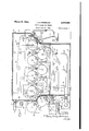
Fig. 2 is a longitudinal vertical sectional view through the conditioning or drying chamber shown diagrammatically in Fig. 1b at the end of the series of drying rolls; I
Fig.3 is a vertical sectional view 3-3 of Fig. 2; .n
Fig. 4 is a diagrammatic view showing: the air taken on line conditioning and circulating system for the drying chamber of Figs. 2 and 3; Fig. 5 is a diagrammatic view of an alternate form of air conditioning and circulating system; Fig. 6 is a fragmentary side elevational view of air distributing tubes used in the drying chamber of Fig. 2; and
Fig. '7 is a sectional view taken on line 1l The basic principles and features of my invention may be understood on referring to the paper drier shown diagrammatically in Figs. 1a and 1D.
A wet paper web Ill, after leaving the press rolls of a Fourdrinier machine, enters the left hand end of a series of thirty. heated drying cylinders or drums ll. These drying cylinders ll may have a diameter of about 5 feet. The wet paper web II] as it enters the paper drier may contain over 60% by weight of moisture. The first ten drier drums I I in the series are collectively designated as the wet end section. The next twelve drying cylinders H in the series are designated as the intermediate section." A coating press I2 is placed in between the wet end section and the intermediate section so as to app y coating to the Y partially dried paper web Ill. The last seven drying cylinders II in the series thereof iare,,en-" closed'in a conditioning chamber or housing i3.
shown for pressing the paper web in down against v the surfaces of the drier drums I l. The felts l4 below the moisture content desired for the flnand I5 are carried on a number of idling rolls l6 Although they similar endless felts are provided for holding the. paper web It against the drying cylinders in the wet end and intermediate sections ahead of the values with which the moisture content of the paper web ill" at its finished value of dryness is 'in equilibrium. The seven drier drums II that are enclosed within the conditioning chamber l3 may be heated by steam to a temperature which controlled atmosphere within the chamber. The heat energy supplied to the drying cylinders in this conditioning chamber would be at a much lower rate than that at which heat energy is 5 supplied tothe drying cylinders external of the conditioning chamber. The efiect of this differing rate of heatsupply is very clearly shown.
- In the subsequent table No. 3, in column 6 of said table, entitled Water evaporated, there is 10 a notation that under typical conditions 1572 lbs. of water per ton of paper manufactured were evaporated in the intermediate section of the 12 drying cylinders, whereas only 68 lbs. of water per ton of paper manufactured were evaporated in. the 7 d y cylinders in the conditioning chamber. It will be understood that the invention is not limited to having any particular number of drying cylinders in any particular arrangement, although the number and arrangement thereof as shown in Figs. 1a and 1b has been found to provide a very satisfactory operating paper drier? Illustrative operating data will serve to more clearly show the manner in which the wet paper 5 web'lills dried in the paper drier of Figs. 1a and through the wet end section a, relatively large amount of the moisture is driven ofi so that when the paper web Ill leaves the wet end section and. enters the coatingpress I2 the moisture content will have been reduced to about by weight.
35 A fairly large part of the coating material added to the paper web' I0 in the coating press 12 is water. so that when the paper web leaves the coating press and enters the intermediate section, the moisture content may have been raised up to 40 50% moisture by weight.
In caseit is desired to have the paper web It) dried to a final value within the range of from 7% to 9%,sufiicient moisture will be driven ofi in the intermediate section so that when the paper web leaves this part of the paper drier it will have an average moisture content of about 12% by weight. This moisture content of 12% is an average value for all parts of the paper web which of' course will not be uniformly dry in all parts at this point. Certain parts, particularly at the edges, will be drier than the center parts. However, the moisture content of 12% is sufficiently high so that the driest parts at the sides. of the web will not have been dried ished paper. As the paper web passes thrupthe conditioning chamber l3 its moisture content is reduced to the particular value desired within the range of from 7% to 9%; for example, the
0 paper may be uniformly dried to a value of 8%. The conditions of the atmosphere within the conditioning chamber I3 are such that all parts of the web' will be reduced to the desired value of dryness, while no part is permitted to be dried relationship between the moisture in the paper web. ill and the controlled atmospherein the chamber l3 prevents such overdrying. 0 As the uniformly dried paper web Ill leaves the right hand side of the conditioning chamber l3, it will tend to lose moisture by evaporative cooling and this loss maybe materially reduced by running the web over a water-cooled roll I! I corresponds closely'to the temperature of the before it is'p'assed to the calender stack 20.
below this figure. As stated, the equilibrium The conditioning chamber [3, functions or serves to subject the paper web "I to a conditioned atmosphere of predetermined uniform temperature and humidity as the web passes therethrough. Since there is a certain amount of drying of the paper web [0 taking place within. the chamber 13, some provision must be made for removing the moisture given off therefrom, and circulation means must be provided to maintain the atmosphere uniform throughout and prevent stagnation in local pockets. It will be seen that several different types of construction of the conditioning chamber l3 and associated apparatus for maintaining a uniform atmos-' phere therewithin may be provided. In Figs. 2 and 3 of the drawings, the details of' one form f of the conditioning chamber and associated atmosphere maintaining apparatus which has been found to be satisfactory, is shown.
Since the atmosphere within the conditioning chamber l3 will ordinarily be in the neighborhood of'about 200Ff. to 205? F., the roof and sidewalls of the chamber should be insulated so as to prevent heat loss from the chamber and condensation of moisture i'rom'the atmosphere i therewithin: The roof 25, front and back end walls 26 and 21 respectively, and the floor 28 are indicated as being formed of insulation. The front and back side walls of the chamber l3 should also be insulated as much as is conven- 30 iently permitted in view of the fact that the side walls contain a number of doorspermitting access to the interior of the chamber. The front side wall30 (Fig'. 3) may have a rigid section 3| built from the level of the floor 32 up to about the bottom of the. bearing supports for the lower set of drier cylinders II, and should have another rigid section '33 depending from the roof 25 down to the bearings for the top set of driers I I. Be-, tween-these rigid sections 3| and 3 3, the front side wall 30 should be filled. with quick opening doors 34 which are hinged in the center so as to open up as indicated by the broken line position shown. The quick opening doors 34 permit the operator to quickly open the chamber [3 in order to remove broke as is done in the unhoused or unenclosed driers in the wet end and intermediate sections of the paper drier. The .back or rear side wall 35 should include a door 36 through which the operators may have'access to the bearings in the side frames 31. A catwalk 39 may be provided for greater ease in servicing these bearings. The bearin gs in the right hand or front side frame 38 may be easily reached through the doors 34 in the front side wall 30.
The paper web I!) enters the front end wall 26 through an elongated opening 42 therein and leaves the conditioning chamber l3 through a, similar elongated opening 43 in the rear end wall 21. -In order to seal off the entrance of the paper web into thefront end wall 26, anupper flexible canvas apron 44 is provided which extends down onto the top of the drier drum Ila, and a second apron 45 is provided which rides easily against the felt 46 as it runs over the idling roll 41. This arrangement is very satisfactory for sealing off the entryof the paper web 10 into the chamber l3 without requiring the paper web to be interfered with. A similar sealing arrangement is provided at the rear end wall 21 so as to seal off the exit of the paper web I0 therethrough. An upper-canvas apron 48 is provided which rides againstrthe upper felt M as it runs over the idling roll I 6, and a lower apron 49 rides against ,the surface of the drying cylinder I lb, as shown.
In the conditioning chamber 13, humid air tends to collect in theelongated dead-air pockets formed between the cylinders II, the paper web It, and the fe1ts-j4 and I5. It is important that the moist humid air which collects in these pockets be swept out so as to keep the paper web continuously exposed and subjected to the conditioned atmosphere of controlled temperature, and relative humidity. It is also desirable that and paper web, and in order to keep the upper and lower felts I4 and I5 to the correct moisture content, two sets of air distributing ducts or tubes 53 and 54 are provided. The set of air distributing tubes 53 are somewhat larger than those in the other set of tubes 54, and comprise twelve in number. There are eleven of the smaller set 1 of ducts 54. The air distributing ducts 53 and 54 are of similar construction and are disposed so as to efficiently accomplishtheir purpose of maintaining a uniform, atmosphere within the conditioning chamber I3.
The details of one of the air distributing tubes or ducts 53 are shownin Figs. 6 and 7 of the drawings. The duct 53 comprise a small diameter inner pipe 55 from which a number of short tubes 56 project. The outer ends of these small tubes 56 fit'in an outer cylindrical casing 51. As the conditioned air spurts or shoots out of the small tubes 55, as indicated diagrammatically in Fig. 2, the air stream serves to sweep the air out of the dead air pockets.
In order to supply the two sets of air distributing ducts or tubes 53 and 54 with conditioned air,
manifold means are provided which include a main air supply' duct 60 (Figs. 2 and 3), from which extend a number of smaller air pipes or ducts 6 l The air pipes 6| connect with the larger air distributing ducts 53 and branch "off so as to connect with the\smaller air distributing ducts 54. It will be understood that the manifold means may take several different forms.
Circulation of the conditioned atmosphere in the conditioning chamber I3 is effected by withdrawing the air from the bottom of the chamber, reconditioning the air, and then supplying it under circulating pressure into the main air distributing pipe 60., A wide air suction pipe 65 is provided in. the pit of the conditioning chamber I3 with three inlet branches 66 turned up therefrom at spaced apart intervals. The left hand end of the pipe 65 is connected to the inlet of a blower 61. The discharge side of the blower 61 is connected by a fitting 68 to the air duct 60. An-air heater 10 in the form of a steam coil may be provided in the fitting 68 for heating the re: circulated atmosphere. In case it is necessary to add moisture to the recirculated atmosphere, steam may be supplied from a steam shower 1!. In order to make up for the amount of atmosphere which is lost from the chamber 13 in removing excess moisture out through the exhaust pipe 12 in the upper left hand corner of the chamber (Fig. 2), make-up air may be supplied into the suction pipe 65 through a duct 13 connected therein. Sufficient make-up air may be added through the duct 13 to the recirculated air so as to balance the amount of atmosphere which is withdrawn through the exhaust 12.
A damper 14 is provided in the exhaust outlet 12 so as to control th amount of atmosphere exhausted. The exhausted atmosphere may be carexhaust I2 soas to provide positive control for exhausting the atmosphere.
Wet and dry bulb recording thermometers l and 1B are provided for the main air duct 60' and the exhaust pipe 12 respectively, so that the temperature and relative humidity of the recirculated and exhausted atmospheres may be checked. The temperature and relative humidity of the recirculated air may be controlled by the heater and the steam shower 1 I, while suflicient make-up air is added thru the duct 13 to compensate for the atmosphere removed through the exhaust I2.
As stated, the seven drum drier ll housed in the conditioning chamber l3 are to be maintained at a temperature substantially equal to the temthe moisture given off from the paper web l0 therein is removed.
The four following tables give representative operating data illustrating the operation oi the upon the particular drier'used and the particular perature of the conditioned atmosphere within the chamber. As stated, this temperature may be in the neighborhood of 200 F. to 205 F. Ac-
' cordingly, it will be necessary to heat these dry.-
-of the chamber in the wet end and intermediate sections. The type of control means for maintaming-the drier temperatures is a. matter of choice, although the inside steam temperature type of control may be mentioned as one satisfactory arrangement.
For purposes of an easier understanding of the invention the air conditioning and circulating system for-maintaining the controlled atmosphere within the conditioning chamber l3 (Figs. 2 and 3) is shown diagrammatically in Fig. 4 of the drawings. v
Instead of maintaining the atmosphere at the.
desired relative humidity and temperature by the recirculating system described in connection with Figs. 2, 3 and 4 of the drawings, an aitemate system may be used wherein conditioned ai flows through the conditioning chamber I3 in one pass without recirculation. Such asystem is shown diagrammatically in Fig. 5 of the drawings. In this system the air makes only one pass through the housing l3. Air is drawn into the intake 80 of a blower ill in a predetermined amount. The air is discharged from the blower 8| and passes through a heater 82- and steam shower 83 before it is delivered to the main air duct pipe 60 in the chamber IS. A wet and dry bulb temperature recorder 84 is provided in the delivery duct 85 so type and conditions of the paper being dried.
The four tables are self-explanatory. Table I shows the equilibrium relationship between the moisture in a popular brand of 39# photogravure paper and the relative humidity of air at 200 F. Since the relationship for relative humidity values below 70% to 80% is practically independent of temperature, this table is substantially correct for air at the temperatures from 175 F. to over Table II illustrates the air requirements for the conditioning chamber l3 on the basis of 2000 pounds of paper per hour production, dried to Table III comprises data showing typical I ,amounts of evaporation and steam requirements in the d'gfierent parts of the paper drier when the web is dried to 9% moisture content at a production rate of three and one-quarter tons of paper per hour.
Table IV gives the distribution of air in the two sets of large and small air-distributing tubes or ducts 53 and 54 respectively when a paper web controlled in respect to temperature and relative humidity by operation of the heater 82 and the steamshower 83.
An exhaust fan 86 is provided in the exhaust line 81 leading from the top of the chamber l3 which serves to remove an amount of the atmosphere from the chamber which corresponds to that delivered by the blower 8|. The wet and dry bulb temperature recorder 88 has its temperature responsive elements disposed in the exhaust 81 ior checking the temperature and relative humidity of the exhausted atmosphere. A suificient amount of air is circulated through the chamber l3 so as to insure that the atmosphere therein is maintained at the desired predetermined temperature and relative humidity while is dried to a moisture content of 9%. The data is based on three and one-quarter tons of paper produced per hour.
' Table I [Showing moisture equilibrium between' a popular brand of 3.9# photogravure paper and air at 200 F.]
Per cent relative humidity g t? or air at mime F of paper Table 2 [Air requirements for conditioning chamber on basis of 2000 lbs. of paper/hr. dried to 9% moisture content air to enter and leave at 200 F.] l
Table 3 [Ming typical amount: of evaporation and steam requirement! in diflrent part: ofthe paper drier when web is dried to 9% moisture conin pounds per ton of paper produced] Part of this steam will be used to heat the air circulated through the conditioning chamber. The remainder will be used in the drying cylinders.
housing, means for regulating the temperature and humidity of the air which is supplied to said housing so as to maintain an atmosphere or controlled, predetermined humidity and temperature I Interme- Condi- Wet and section. Coating gg 33335 11 q f 12 7 drying cylinders cylinders r l 1 Bone dry solids leaving section l, 720 1, 820 l, 820 1, 820 2 Entering consistence per cent-- 37 66 50 88 3 Water entering 2, 980. 886 1,820 248 4 Leaving consistence 66 5O 88 per can 91 a Water leaving--.- ass 1,820 248 180 6 Water evaporated. 2, 044 -934 1, 572 68 7 Evaporation equivalent to, heat to warm web-to 165 F. to 185 F 280 194 8 Sumofitemsfiand7. 2,324 l, 766 68 9 Steam required per 7 ton 0! paper (item 8 times 125 2, 905 2, 208 85 10 Production at 600 I. p. in
tons per hour" 3% 11 Steam required per hour 9, 441 7, 175 276 12 Total steam per hour I 16, 894
1 Water added by coating.
within said housing which is in equilibrium with the moisture content'of the paper web when dried to said predetermined uniiorm dryness, and heating control means operable to supply heat energy to the drying cylinders enclosed in said housing at a much lesser rate than that at which heat energy is supplied to the cylinders external to s rid housing, said control means being operable to maintain the temperature or said enclosed drying cylinders and at a value substantially equal to the temperature of the atmosphere in said chamber.
2. In a paper making machine, a paper drier for drying a continuous, wet paper web to a predetermined uniform moisture content, which comprises, in combination, a series of drying cylinders into one end of which the wet paper is fed, means including a source oi. heat energy for heating said drying cylinders, means for driving said cylinders whereby said paper web is passed over each of said cylinders and through said series thereof, a housing enclosinga plurality of the heated dryingcylinders at the end of said series thereof opposite to the end into which the wet paper web is fed, endless felts Table 4 [Distribution ofair in duct: 53 and 64 for drying web to 9Z3 miilature content-data on basis 0) tons of production I per our R I Distribution of airin chamber (0. i. m.) (3% Air to be tons paper per hour) Water to be evaporated in or makechamber up (c7 1'. Total air Air (c. i. m.) Air (0. i. m.) R H m.) (c. t. m.) for to each oi the to each of the Consistency 6 F the chamber ducts 53 ducts 54 0! web en- 01 i tering the in the chamber chamber R. H. diileren- R. H. difleren- R. H. difleren- Lbs tial between tial between tial between Lbs. per hr R. H. of entering and entering and entering and ton of 5 to exhaust air exhaust air exhaust air paper 2g 200 F.
Per cent Per cent It will be understood that the nature of this invention permits a number of modifications and arrangements to be made in respect to the construction of the paper drier apparatus and .the methods of operation thereof, all of which will be within the broad scope of this invention. Accordingly, it is intended that all matter described above or shown in connection with the accompanying drawings is to be interpreted as illustrative of the invention and is not to be construed in a limited sense.
I claim:
1. In a paper making machine, a paper drier for drying a continuous, wet paper web to a predetermined uniform moi'sture content, which comprises a seriesof drying cylinders into one thereof, a housing enclosing a plurality of the drying cylinders at the end of said series'opposite to the end into which the wet paper web is fed, means for supplying drying air to said supported on idler rollers for pressing the paper web onto the drying cylinders in said housing, a plurality of air-distributing tubes disposed lonitudinally in the dead air pockets in said housing formed by said felts, paper web, and drying cylinders, a recirculating system including a circulating fan connected so as to withdraw air from said housing and to deliver air to said airdistributing tubes, a heater in said recirculating system for heating the recirculated air, an air I make-up supply connected with said recirculating system for adding relatively dry make-up air to the system, an exhaust connected with said housing through which part of the atmosphere therein may be exhausted, heating control means operable to maintain the temperature of the drying surfaces of the drying cylinders enclosed in said'housing at substantially the same temperature as the atmosphere within said housing,v and operable to supply heat energy to the drying cylinders enclosed in said housing at a much lesser rate than that at which heat energy is supplied to the cylinders ahead of said housing whereby moisture is removed from the wet aper web at a'sufliciently rapid rate during its passage through the drying cylinders ahead of 'said housing that the paper web'enters said nous: 'ing with its driest parts having a moistur content only slightly above the predetermined value of dryness desired, and means for regulating the temperature and humidity of the air delivered to said air distributing tubes from said recirhousing and suiiicient make-up air being addedthrough said air make-upsupply tomake up for the atmosphere exhausted.
3. The'method of continuously drying a wet paper web on a multiple roll drier of th class described to a predetermined moisture content which is uniform across the width of the web, which comprises rapidly reducingv the moisture contentof the web'to a point where the driest portion of the web contains 'just slightly more moisturethan said predetermined value, by pass ing the web over a number of the drying cylinders of the drier to which heat energy is supplied at a high rate, and then slowly reducing the remaining moisture content of the web to said predetermined, uniform value by passing the web over additional drying cylinders, to which heat energy is supplied at a much lower rate than that at which heat energy i supplied to said first mentioned drying, cylinders, while simultaneously subjecting the web to a conditioned atmosphere, the temperature of said additional thereof is at said predetermined 'value, the web being on said additional drying cylinders and being subjected to said conditioned atmosphere for a suflicientperiodof time with relation to the rate at which heat energy is supplied tosaid additional drying cylinders to attain said equilibrium condition in all parts thereof.
4. The method of continuously drying a wet paper web on a multiple roll drier of the class described. to a predetermined moisture content which is uniform across the width of the web and which is within the range 01' from about 4 to 10% by weight, which comprises rapidly reducing the moisture content of the web to a point where thedriest portion thereof contains not less than about 12% by weight of moisture by passing the web over a number of the drying cylinders of the drier to which heat energy is supplied at a high rate,.and then slowly reducing the remaining moisture content of the web to said predetermined, uniform value by passing the web over additional drying cylinders, to which heat energy is supplied at a much lower rate than that at which heat energy is supplied to said first mentioned drying cylinders, while simultaneouslysubjecting the web to a conditioned atmosphere, the temperature of said additional drying cylinders and the temperature and humidity of said conditioned atmosphere being so correlated that equilibrium conditions will be achieved in'said web when the moisture content thereof is at said predetermined value, there being sufficient cylinders in said last mendrying cylinders and the temperature and humid-E ity of said conditioned atmosphere being so correlated that equilibrium conditions will be achieved in said web when the moisture content is supplied thereto being such as to assure that the Web shall attain said equilibrium condition in all parts thereof.
JOHN R. FANSELOW.
Priority Applications (1)
| Application Number | Priority Date | Filing Date | Title |
|---|---|---|---|
| US400286A US2344686A (en) | 1941-06-28 | 1941-06-28 | Paper drier and method |
Applications Claiming Priority (1)
| Application Number | Priority Date | Filing Date | Title |
|---|---|---|---|
| US400286A US2344686A (en) | 1941-06-28 | 1941-06-28 | Paper drier and method |
Publications (1)
| Publication Number | Publication Date |
|---|---|
| US2344686A true US2344686A (en) | 1944-03-21 |
Family
ID=23582981
Family Applications (1)
| Application Number | Title | Priority Date | Filing Date |
|---|---|---|---|
| US400286A Expired - Lifetime US2344686A (en) | 1941-06-28 | 1941-06-28 | Paper drier and method |
Country Status (1)
| Country | Link |
|---|---|
| US (1) | US2344686A (en) |
Cited By (17)
| Publication number | Priority date | Publication date | Assignee | Title |
|---|---|---|---|---|
| US2931107A (en) * | 1956-02-13 | 1960-04-05 | American Cyanamid Co | Drying apparatus |
| US3041736A (en) * | 1958-03-28 | 1962-07-03 | Union Carbide Corp | Method and apparatus for drying regenerated cellulose tubing |
| US3049809A (en) * | 1956-02-13 | 1962-08-21 | American Cyanamid Co | Method of drying filamentary material |
| US3079699A (en) * | 1958-10-27 | 1963-03-05 | American Viscose Corp | Web humidifying method |
| DE1150323B (en) * | 1959-07-30 | 1963-06-12 | Svenska Flaektfabriken Ab | Desiccant distribution pipe closed at one end |
| US3183606A (en) * | 1959-10-21 | 1965-05-18 | Svenska Flaektfabriken Ab | Device in press-roll sections for dewatering cellulose pulp webs |
| US3191312A (en) * | 1961-04-17 | 1965-06-29 | Svenska Flaektfabriken Ab | Method of uniformly moistening paper and like hygroscopic web material |
| US3266164A (en) * | 1963-04-03 | 1966-08-16 | Fitchburg Paper | Drying pulp and paper by a high frequency electric field |
| US3432936A (en) * | 1967-05-31 | 1969-03-18 | Scott Paper Co | Transpiration drying and embossing of wet paper webs |
| DE1295353B (en) * | 1964-11-12 | 1969-05-14 | Aschaffenburger Zellstoffwerke | Device for moistening paper webs or the like. |
| US3489283A (en) * | 1967-07-24 | 1970-01-13 | Phillips Petroleum Co | Liquid-solids separation method |
| USRE28459E (en) * | 1966-06-07 | 1975-07-01 | Transpiration drying and embossing of wet paper webs | |
| US4168579A (en) * | 1976-11-19 | 1979-09-25 | Ericsson Sylve J D | Drying apparatus incorporating an air-moistening device |
| US4272316A (en) * | 1979-05-29 | 1981-06-09 | Beloit Corporation | Steam shower |
| US5756156A (en) * | 1995-02-01 | 1998-05-26 | Valmet Corporation | Method for producing surface-treated paper and dry end of a paper machine |
| US6126787A (en) * | 1995-02-01 | 2000-10-03 | Valmet Corporation | Dry end of a paper machine |
| US20120216420A1 (en) * | 2007-02-09 | 2012-08-30 | Usnr/Kockums Cancar Company | Method and apparatus for controlling cooling temperature and pressure in wood veneer jet dryers |
-
1941
- 1941-06-28 US US400286A patent/US2344686A/en not_active Expired - Lifetime
Cited By (21)
| Publication number | Priority date | Publication date | Assignee | Title |
|---|---|---|---|---|
| US3049809A (en) * | 1956-02-13 | 1962-08-21 | American Cyanamid Co | Method of drying filamentary material |
| US2931107A (en) * | 1956-02-13 | 1960-04-05 | American Cyanamid Co | Drying apparatus |
| US3041736A (en) * | 1958-03-28 | 1962-07-03 | Union Carbide Corp | Method and apparatus for drying regenerated cellulose tubing |
| US3079699A (en) * | 1958-10-27 | 1963-03-05 | American Viscose Corp | Web humidifying method |
| DE1150323B (en) * | 1959-07-30 | 1963-06-12 | Svenska Flaektfabriken Ab | Desiccant distribution pipe closed at one end |
| US3183606A (en) * | 1959-10-21 | 1965-05-18 | Svenska Flaektfabriken Ab | Device in press-roll sections for dewatering cellulose pulp webs |
| US3191312A (en) * | 1961-04-17 | 1965-06-29 | Svenska Flaektfabriken Ab | Method of uniformly moistening paper and like hygroscopic web material |
| US3266164A (en) * | 1963-04-03 | 1966-08-16 | Fitchburg Paper | Drying pulp and paper by a high frequency electric field |
| DE1295353B (en) * | 1964-11-12 | 1969-05-14 | Aschaffenburger Zellstoffwerke | Device for moistening paper webs or the like. |
| USRE28459E (en) * | 1966-06-07 | 1975-07-01 | Transpiration drying and embossing of wet paper webs | |
| US3432936A (en) * | 1967-05-31 | 1969-03-18 | Scott Paper Co | Transpiration drying and embossing of wet paper webs |
| US3489283A (en) * | 1967-07-24 | 1970-01-13 | Phillips Petroleum Co | Liquid-solids separation method |
| US4168579A (en) * | 1976-11-19 | 1979-09-25 | Ericsson Sylve J D | Drying apparatus incorporating an air-moistening device |
| US4272316A (en) * | 1979-05-29 | 1981-06-09 | Beloit Corporation | Steam shower |
| US5756156A (en) * | 1995-02-01 | 1998-05-26 | Valmet Corporation | Method for producing surface-treated paper and dry end of a paper machine |
| US6126787A (en) * | 1995-02-01 | 2000-10-03 | Valmet Corporation | Dry end of a paper machine |
| US6193840B1 (en) | 1995-02-01 | 2001-02-27 | Valmet Corporation | Method for producing surface-treated paper |
| US20120216420A1 (en) * | 2007-02-09 | 2012-08-30 | Usnr/Kockums Cancar Company | Method and apparatus for controlling cooling temperature and pressure in wood veneer jet dryers |
| US8667703B2 (en) * | 2007-02-09 | 2014-03-11 | Usnr/Kockums Cancar Company | Method and apparatus for controlling cooling temperature and pressure in wood veneer jet dryers |
| US9228780B2 (en) | 2007-02-09 | 2016-01-05 | Usnr, Llc | Method and apparatus for controlling cooling temperature and pressure in wood veneer jet dryers |
| US9797655B2 (en) | 2007-02-09 | 2017-10-24 | Usnr, Llc | Method and apparatus for controlling cooling temperature and pressure in wood veneer jet dryers |
Similar Documents
| Publication | Publication Date | Title |
|---|---|---|
| US2344686A (en) | Paper drier and method | |
| US2091805A (en) | Paper making method and machine | |
| US4247990A (en) | Method for controlling the moisture content of a web of sheet material | |
| US3089252A (en) | Web moisture profile control for paper machine | |
| US1718573A (en) | Paper-making method and machine | |
| US5647141A (en) | Process and apparatus for drying sheet materials | |
| KR100205102B1 (en) | Method in the drying of a paper web as well as dryer sections of a paper machine | |
| US3110575A (en) | Porous belt drying apparatus | |
| FI116376B (en) | Method and apparatus for treating a web of material | |
| US5033207A (en) | Device for drying a material web | |
| US6128833A (en) | Dryer-section concept and method in the drying of a paper/board web | |
| US2939222A (en) | Method for drying or other treatment of a web-like material | |
| US2281496A (en) | Air drier for paper | |
| US3815254A (en) | Method and apparatus for controlling the amount of moisture removed from material | |
| US2061976A (en) | Process and apparatus for the drying of travelling webs | |
| US3242583A (en) | Method of drying a running web of sheet material | |
| US1438511A (en) | Paper-making machine | |
| FI104194B (en) | Pulp drying section, pulp drying method and pulp drying blade | |
| US6094838A (en) | Curl and profile correction with high velocity hoods | |
| US1656853A (en) | Paper machinp | |
| US2929153A (en) | Drying apparatus for sheet material | |
| US2616188A (en) | Web drying apparatus | |
| US2000546A (en) | Paper drying process and apparatus | |
| US1595473A (en) | Method and apparatus for drying sheet material | |
| US3376653A (en) | Dryer ventilation |