US2348178A - Method of making metallic products of sheetlike form - Google Patents
Method of making metallic products of sheetlike form Download PDFInfo
- Publication number
- US2348178A US2348178A US172516A US17251637A US2348178A US 2348178 A US2348178 A US 2348178A US 172516 A US172516 A US 172516A US 17251637 A US17251637 A US 17251637A US 2348178 A US2348178 A US 2348178A
- Authority
- US
- United States
- Prior art keywords
- metal
- belt
- annulus
- molten metal
- heat absorbing
- Prior art date
- Legal status (The legal status is an assumption and is not a legal conclusion. Google has not performed a legal analysis and makes no representation as to the accuracy of the status listed.)
- Expired - Lifetime
Links
- 238000004519 manufacturing process Methods 0.000 title description 8
- 229910052751 metal Inorganic materials 0.000 description 171
- 239000002184 metal Substances 0.000 description 171
- 239000000047 product Substances 0.000 description 42
- 238000000034 method Methods 0.000 description 36
- 239000002826 coolant Substances 0.000 description 16
- 238000001816 cooling Methods 0.000 description 15
- 239000007789 gas Substances 0.000 description 13
- XLYOFNOQVPJJNP-UHFFFAOYSA-N water Substances O XLYOFNOQVPJJNP-UHFFFAOYSA-N 0.000 description 12
- 230000002093 peripheral effect Effects 0.000 description 11
- 239000013078 crystal Substances 0.000 description 9
- 239000000463 material Substances 0.000 description 9
- RYGMFSIKBFXOCR-UHFFFAOYSA-N Copper Chemical compound [Cu] RYGMFSIKBFXOCR-UHFFFAOYSA-N 0.000 description 7
- 229910000831 Steel Inorganic materials 0.000 description 7
- 230000000694 effects Effects 0.000 description 7
- 230000008569 process Effects 0.000 description 7
- 239000010959 steel Substances 0.000 description 7
- 229910045601 alloy Inorganic materials 0.000 description 6
- 239000000956 alloy Substances 0.000 description 6
- 229910052802 copper Inorganic materials 0.000 description 6
- 239000010949 copper Substances 0.000 description 6
- 238000002425 crystallisation Methods 0.000 description 6
- 230000008025 crystallization Effects 0.000 description 6
- 239000007788 liquid Substances 0.000 description 6
- 239000000853 adhesive Substances 0.000 description 5
- 230000001070 adhesive effect Effects 0.000 description 5
- 230000033001 locomotion Effects 0.000 description 5
- 150000002739 metals Chemical class 0.000 description 5
- 239000007787 solid Substances 0.000 description 5
- 230000009471 action Effects 0.000 description 4
- 238000005266 casting Methods 0.000 description 4
- 230000003628 erosive effect Effects 0.000 description 4
- 230000005484 gravity Effects 0.000 description 4
- 239000004033 plastic Substances 0.000 description 4
- 230000004044 response Effects 0.000 description 4
- 238000005204 segregation Methods 0.000 description 4
- 230000008901 benefit Effects 0.000 description 3
- 238000004891 communication Methods 0.000 description 3
- 239000012535 impurity Substances 0.000 description 3
- 238000002844 melting Methods 0.000 description 3
- 230000008018 melting Effects 0.000 description 3
- 230000000704 physical effect Effects 0.000 description 3
- 238000005096 rolling process Methods 0.000 description 3
- 239000007921 spray Substances 0.000 description 3
- 238000009736 wetting Methods 0.000 description 3
- QGZKDVFQNNGYKY-UHFFFAOYSA-N Ammonia Chemical compound N QGZKDVFQNNGYKY-UHFFFAOYSA-N 0.000 description 2
- IJGRMHOSHXDMSA-UHFFFAOYSA-N Atomic nitrogen Chemical compound N#N IJGRMHOSHXDMSA-UHFFFAOYSA-N 0.000 description 2
- 101100379079 Emericella variicolor andA gene Proteins 0.000 description 2
- 239000011358 absorbing material Substances 0.000 description 2
- 238000006243 chemical reaction Methods 0.000 description 2
- 230000008602 contraction Effects 0.000 description 2
- 239000000498 cooling water Substances 0.000 description 2
- 238000005336 cracking Methods 0.000 description 2
- 230000007547 defect Effects 0.000 description 2
- 230000001419 dependent effect Effects 0.000 description 2
- 238000005755 formation reaction Methods 0.000 description 2
- 210000004907 gland Anatomy 0.000 description 2
- 230000017525 heat dissipation Effects 0.000 description 2
- 238000011835 investigation Methods 0.000 description 2
- 239000000203 mixture Substances 0.000 description 2
- 239000012768 molten material Substances 0.000 description 2
- 238000012856 packing Methods 0.000 description 2
- 238000005192 partition Methods 0.000 description 2
- 239000011819 refractory material Substances 0.000 description 2
- 229910052709 silver Inorganic materials 0.000 description 2
- 239000004332 silver Substances 0.000 description 2
- 239000011343 solid material Substances 0.000 description 2
- 230000002269 spontaneous effect Effects 0.000 description 2
- 239000000126 substance Substances 0.000 description 2
- 238000012546 transfer Methods 0.000 description 2
- 229910000906 Bronze Inorganic materials 0.000 description 1
- VYZAMTAEIAYCRO-UHFFFAOYSA-N Chromium Chemical compound [Cr] VYZAMTAEIAYCRO-UHFFFAOYSA-N 0.000 description 1
- 229910000881 Cu alloy Inorganic materials 0.000 description 1
- CWYNVVGOOAEACU-UHFFFAOYSA-N Fe2+ Chemical compound [Fe+2] CWYNVVGOOAEACU-UHFFFAOYSA-N 0.000 description 1
- BQCADISMDOOEFD-UHFFFAOYSA-N Silver Chemical compound [Ag] BQCADISMDOOEFD-UHFFFAOYSA-N 0.000 description 1
- 239000006096 absorbing agent Substances 0.000 description 1
- -1 alloys Chemical class 0.000 description 1
- 229910052782 aluminium Inorganic materials 0.000 description 1
- XAGFODPZIPBFFR-UHFFFAOYSA-N aluminium Chemical compound [Al] XAGFODPZIPBFFR-UHFFFAOYSA-N 0.000 description 1
- 229910021529 ammonia Inorganic materials 0.000 description 1
- 238000012550 audit Methods 0.000 description 1
- 230000015572 biosynthetic process Effects 0.000 description 1
- 239000010974 bronze Substances 0.000 description 1
- 229910052804 chromium Inorganic materials 0.000 description 1
- 239000011651 chromium Substances 0.000 description 1
- 239000004020 conductor Substances 0.000 description 1
- 239000000470 constituent Substances 0.000 description 1
- 238000010276 construction Methods 0.000 description 1
- 238000004320 controlled atmosphere Methods 0.000 description 1
- KUNSUQLRTQLHQQ-UHFFFAOYSA-N copper tin Chemical compound [Cu].[Sn] KUNSUQLRTQLHQQ-UHFFFAOYSA-N 0.000 description 1
- 230000007423 decrease Effects 0.000 description 1
- 210000001787 dendrite Anatomy 0.000 description 1
- 238000013461 design Methods 0.000 description 1
- 238000009826 distribution Methods 0.000 description 1
- 238000001125 extrusion Methods 0.000 description 1
- 238000005242 forging Methods 0.000 description 1
- 230000004927 fusion Effects 0.000 description 1
- 238000010438 heat treatment Methods 0.000 description 1
- 239000001257 hydrogen Substances 0.000 description 1
- 229910052739 hydrogen Inorganic materials 0.000 description 1
- 125000004435 hydrogen atom Chemical class [H]* 0.000 description 1
- 239000011261 inert gas Substances 0.000 description 1
- 230000000266 injurious effect Effects 0.000 description 1
- 230000002452 interceptive effect Effects 0.000 description 1
- 235000000396 iron Nutrition 0.000 description 1
- 239000007769 metal material Substances 0.000 description 1
- 238000012986 modification Methods 0.000 description 1
- 230000004048 modification Effects 0.000 description 1
- 230000007935 neutral effect Effects 0.000 description 1
- 229910052757 nitrogen Inorganic materials 0.000 description 1
- 230000003647 oxidation Effects 0.000 description 1
- 238000007254 oxidation reaction Methods 0.000 description 1
- 238000007747 plating Methods 0.000 description 1
- 230000001681 protective effect Effects 0.000 description 1
- 230000003134 recirculating effect Effects 0.000 description 1
- 230000009467 reduction Effects 0.000 description 1
- 230000002829 reductive effect Effects 0.000 description 1
- 238000011160 research Methods 0.000 description 1
- 230000000717 retained effect Effects 0.000 description 1
- 239000002893 slag Substances 0.000 description 1
- 238000009751 slip forming Methods 0.000 description 1
- 238000007711 solidification Methods 0.000 description 1
- 230000008023 solidification Effects 0.000 description 1
- 238000005507 spraying Methods 0.000 description 1
- KDYFGRWQOYBRFD-UHFFFAOYSA-N succinic acid Chemical compound OC(=O)CCC(O)=O KDYFGRWQOYBRFD-UHFFFAOYSA-N 0.000 description 1
- 239000013589 supplement Substances 0.000 description 1
- 238000003466 welding Methods 0.000 description 1
Images


Classifications
-
- B—PERFORMING OPERATIONS; TRANSPORTING
- B22—CASTING; POWDER METALLURGY
- B22D—CASTING OF METALS; CASTING OF OTHER SUBSTANCES BY THE SAME PROCESSES OR DEVICES
- B22D11/00—Continuous casting of metals, i.e. casting in indefinite lengths
- B22D11/06—Continuous casting of metals, i.e. casting in indefinite lengths into moulds with travelling walls, e.g. with rolls, plates, belts, caterpillars
Definitions
- This invention relates to a new methodoirv making a new product, namely, a metallic product in sheet or strip form.
- An object of my invention is to provide a. commercial procedurel for manufacturing-'metallic strip which is simpler and more effective than any procedure heretofore employed commercially and which involvesl forming sheet or stripflikel l product .direct from molten metal without the necessity of employing intermediate steps such l0 as the usual casting and rolling procedures.
- a metal in the molten state acts like most other liquids. It exhibits the physical ehm-m- 4l' terlstic of surface tensioninvarying degrees and dependent somewhat upon the particular metal l and its temperature, but its principal characteristics, at ordinary industrial pouring temperatures, are its liquid-like 'free mobility4 resulting 'from the reduced cohesive forc between its atomic or molecular constituents;l its ability to readily shape itself in response to applied orfconiining forces; its ability to wet most materials (Cl. zit-200.1)
- vself-levcuiig characteristic under uniformly cpplied forces such as gravity or other ydirectional forces.
- My new method takes advantage of such inherent ,physical characteristics as are exhibited by molten metal at ordinary industrial pouring temperatures and involves utilizing those vcharacteristics in the productionof a liquid layer of controlled width and thickness and in then cooling 'the same to the solidilication temperature, and delivering the solid continuous nat or sheet-like product so formed.
- My new method broadly consists in creating controlled ilow of molten metal existing at a predetermined temperature, such, for example, as the ordinary industrial pouring temperature, andl v in interceptlng the flow with an extended, clean,
- My invention also involves new and improved apparatus for continuously producing strip from p molten metal, such las steel, and'while I have illustrated various modifications oi.' such appaf ratus, each such embodiment is so formed that it is capable of carrying forward more or less speciilc procedure which involves creating-a substantially uniform flow of molten metal in the form of aconilned stream; laying such stream on a substantially horizontally disposed, rapidly .moving heat absorbing surface capable of being wet by the molten metal; accomplishing the delivery of the molten metal to such surface so as to eliminate the effect of the turbulence inthe stream at the point of initial contact between molten metal and 4heat abmrbing surface; and
- the metal of the layer is self-leveling hydrostatically while still molten and highly plastic but is rapidly chilled by reason of its extended surface, and is converted into a solid strip of substantially uniform width and thickness which is first carried by the absorbing surfacoby reason of the gripping contact between it and the surface, but which shrinks as it cools and is thus freed from the supporting and cooling surface without any interfering factors.
- the width of the strip so formed can be controlled by controlling the width of the molten metal stream as it is delivered to the heat absorbing surface and I have discovered that the thickness of the strip may be controlled within close limits by controlling the relationship be- Vtween the velocity of the absorbing surfae and the velocity of ilow of the molten stream delivered thereto.
- the cross section of the metal strip is determined and controlled within close limits, by the following relation: Cross sectional area of the strip multiplied by the velocityof the heat absorbing surface equals the cross sectional areav of the molten streamqielivered to the surface) multiplied by the ⁇ velocity of thel flow of that stream.
- a nozzle such as above described, delivers molten metal to such a heat absorbing surface under conditions such that there is little or no turbu ience at the zone of initial contact between the stream and the heat absorbing surface
- the width of the resulting layer and strip will be substantially that of the nozzle, consequently in the above example the gage of the strip or film will be .04 divided by 2 or .020 inch.
- the absolute contact between the metal and the surface makes it possible to consider the twoas a single bi-metallic section in determining heat exchange conditions.
- the heat exchange between the molten layer and the solidor heatabsorbing layer and throughout their respective thicknesses is directly proportional to the heat conductivity of each layer and the heat gradient involved, consequently the above known factors make it possible to determine the length of time that contact must be maintained between ythe two layers in order to solidify the molten layer and free it from the heat absorbing layer. That the,forces heretofore enumerated, but also selecting a heat absorbing surface whichis wetted by the particular molten metal acted upon.
- the product of my improved procedure is characterized by minute stringer-like crystals at random,l and all substantially identical in size and uniformly and homogeneously distributed throughout the mass of the finished product.
- thevstrip-like product is characterized by .a uniformity of chemical composition identical to that of the molten metal supplied by the melting furnace and free from variations and defects, such as are inherited from a primary ingot structure and as are occasioned byv selective segregation of component metals and concentration of impurities at the grain boundaries of columna'l crystals, gaspockets, etc.
- 'Ille material is also free from the directional effect such as is ordinarily occasioned by mechanical working and crushing of the large place under conditions such that heat is not only rapidly delivered to the relatively cold heatabsorbing velement but-also while the metal, being so cooled, exists in layer-like form.
- a layer of long columnar crystals also called4 dendritic crystals which characterize ingpt and other Acast-formations.
- This new product how everfrgtains most of the above-described characteristics and advantages of its new primary crystalline structure after mechanical working,
- an object of my invention is to provide new'and improved apparatus for producing strip direct ⁇ from molten metal.
- a further object is to produce flat metallic material, such as strip, having new and improved physical properties and characteristics.
- Figure l is a diagrammatic vertical sectional view ofY a machine embodying my invention andv in which the improved molten metal is deliv ered tothe surface of a rapidly moving heat absorbing element in the form of ran endless belt;
- Fig. 2 is a vertical sectional view, on an en larged scale, and illustrates a modication of a A structural detail of the machine shown in Fig. 1:
- Fig. 3 is a view corresponding to Fig. 2 but diagrammatically illustrating a forming roll in such relationship tothe associatedv parts that it coactswith the heat absorbing element in the production of the ilnished product; Y
- Fig. 4 is a diagrammatic, sectional view of modified form of apparatus in which the heat absorbing element is in the form of a rigid annulus
- I such as a ring or cylinder
- Fig. -5 is a diagrammatic, fragmental, lsectional view of a machine similar to the machine cf Fig. 4 but illustratingstructural-variations;
- iiig. 6 is a side elevation of a machine, such as is generally illustrated in Fig. 4 or ⁇ iiig. 5;
- Fig. 7 is a fragmental, sectional view of a machine, such as is illustrated in Fig. ll, but equipped with a rotary metering valve;
- Fig. 8 is a view in side and sectional elevation of a ring type machine equipped with structural features similar to those illustrated in preceding views;
- Fig. 9 is a diagrammatic view illustrating the gearing employed in connection with the machine of Fig. 8;
- Fig. 10 is a iragmental, transverse, sectional view of a water jacketed strip forming ring and illustrates means for driving the ring;
- Fig. 11 is a vertical, sectional view of the machine diagrammatically illustrated in Fig. 8;
- Fig. l2 is a diagrammatic top plan view of the machine shown inFig. 8.
- Fig. 13 is a diagrammatic, fragmental, sectional view of apparatus such as disclosed in Fig. 8 and illustrates accessories which may be employed in connection therewith.
- Fig. l is a diagrammatic illustration oi a simple but effective machine for carrying out my new process.
- the heat absorbing agent is in the form of an endless belt or band, preferably made from metal having high heat conductivity, such,
- the belt is so mounted that one strand or reach is not only substantially horizontal, but is also substantially fiat and is adapted to receive molten metal delivered from an associated nozzle.
- 'I'he arrangement is also such that a stream of molten metal of controlled width, flow and temperature is, in e'ect. laid upon the belt while the belt is moving at a uniform rate in the general direction of stream ilow and at a velocity such that the stream is drawn out into a layer of the desired thickness o1' the ilnished product.
- the continuous stream of metal is so laid upon the moving belt as to substantially eliminate turbulence but at the same time create a continuous and controlled flow on the belt so that the finished product can be produced in continuous or strip-like form.
- the 'I'he heat absorbing belt is so constructed with relation to heat absorbing. ability and is so positioned, with relation to the molten metal delivery nozzle, and is so cooled that itis capable ol' chilling the metal contacting therewith to the solidiflcation temperature while such metal is retained ilat, and all without raising the temperature of the belt above a safe and predetermined temperature. That is to say, the belt is so constructed and proportioned with relation to its heat absorbing capacity and available cooling facilities that the temperature thereof is nover raised to such a point as to occasion welding, surface pitting, cracking or erosion, or the warping of the belt. In addition.
- the belt and its supports are so positioned, relatively to the molten metal delivery nozzle, that the time of contact between each portion of the belt and the metal supported thereby is sufilcient to not only insure solidiflcation of the molten metal, but also its free release from the belt under such conditions that it will be propelled. by the forces previously acting on it, in substantially the direction of its travel while in gripping contact with the beit.
- aA heat absorbing, element I in the form of an endless belt, is mounted on spaced pulleys 2 and 3, which are suitably Journaled on a frame l including a table la.
- the pidiera 2 and 3 are so located, within relation to each other, that the'upper reach or leg of the belt is substantially horizontal and is located immediately above the table la.
- a nomic 5, for delivering molten metal onto the upper reach of the belt is shown formed as a part of a molten metal receptacle 6, which is mounted on the machine frame and is adjustable therealong and lengthwise of the upper reach of the belt I.
- any suitable means may be employed tor driving the belt, consequently .I merely note that the pulley 2 is mounted on shaft I and that the shaft 'I isa driving shaft which may be, and preferably is motivated by a motor, the speed of ⁇ which may be adjusted.
- I employ means for taking up the slack in the belt and this means is illustrated as a hydraulic cylinder I carried by the frame l and provided with a piston 9 operatively connected to the bearing block of the pulley 3.
- the cylinder is shown as provided with an inlet port I0 through winch liqui d under pressure is admitted.
- I. also provide grooved guides I I mounted on the machine frame and each adapted to receive one lateral edge of the upper reach oi' the belt I as the belt leaves the pulley 3 and moves across the table la and onto the pulley 2.
- the delivery end, of the nozzle 5 is located immediately above the upper reach of the belt and at a point intermediate the pulleys 2 and I.
- the receptacle l is shown as provided with a refractory lining and is divided into two compartments I2 and Il', which communicate with each other through a continuously submerged port Il.
- 'Ihe compartment I3 communicates directly with the nozzle I and is preferably of substantially greater capacity than the compartment I2, which is adapted to receive molten metal direct from a furnace or ladle.
- I have shown a diagrammatic representation of a ladle I5 so suspended that its pouring apparatus Il is delivering molten metal into the compartment I2. With this arrangement, slag and other impurities tend to float to the top of the metal within the compartment I2,
- the belt I is so driven by the pulley 2 that it moves in the direction of the arrows-of Fig. 1 and its upper reach, therefore, moves in the generalI direction of the ilow of metal through the nozzle 5 and onto it.. a
- the cooling means includes a liquid delivery pipe I1, which communicates with and supplies cooling medium to spray pipes Il, which extend along and below the lower reach of the belt and are provided with spray apertures', for directing cooling medium on the lower sur-y lace of the belt.
- a liquid delivery pipe I1 which communicates with and supplies cooling medium to spray pipes Il, which extend along and below the lower reach of the belt and are provided with spray apertures', for directing cooling medium on the lower sur-y lace of the belt.
- One or more rubber. squeegees I9 are so mounted on the machine frame that they bear on the belt I at a point beyond the delivery of coolant thereto so that all traces of coolant are wiped oil' of the surface of the belt as it moves toward and onto the pulley 3.
- the squeegees are located within the confines oi' a tank 20, which extends throughout the length of the belt, is located below ilo-e spray pipes IB and is adapted to receive the coolant issuing therefrom and dripping from thebelt.
- the tank is Provided with a drain port '20"iand if desired ordinary and well knownI means may be employed for recirculating the coolant collected within the In Fig. 1 I have shown the machine provided with a product-receiving table 2
- the arm 22 is so formed that its upper face-i. e., its product-receiving and directing facelies within or just below the plane defined by the upper reach of the belt.
- a protective hood 22 for the pur- .pose of preventing oxidation of the holten metal as it is delivered onto and moves with the belt I.
- the hood is in the form of a shield which encloses a portion of the upper reach of the belt and which is secured to the receptacle 6 or the portion thereof which deilnes the nozzle-5.
- 'Ihe hood is provided with a gas delivery pipe 24 and may be provided with a gas discharge pipe 25. yThat is to say, the arrangement is such that ari/inert atmosphere may be maintained within t e hood by reason of the delivery thereto of an inert gas, such as hydrogen, nitrogen, ammonia fgas, etc.
- the adjustment'of the receptacle 6 along, the belt may be accomplished in a number of more or less obvious ways and fonthis reason I have diagrammatically illustrated it as associated with an ordinary positioning screw l26, which is threaded Athrough a fixed or stationary bracket 2i' of the machine frame.
- Such an arrangement provides means for adjusting the position of the nozzle i along the upper reach of the belt and for locking l it in the adjusted position.
- This metal passes through the submerged port I4 -into the compartment Il,
- Thecompartment I3 is preferably of such capacity as to minimize the effect of such variations in heady as may be occasioned by a lack of uniformity compartment I2. f ,c
- the nozzle is so formed and located that the stream of molten metal issuing therefrom is delivered to the surface of the upper reach of the belt without producing undue stream so delivered is controlled as to width and rate of now.
- the width substantially corresponds to that of the nozzle and the ow responds to variations in head within compartment I3, i. el, the cross sectional area of the nozzle 5 and the head of molten metal within the compartment I2 controls the velocity of flow of the molten metal issuing from the nozzle and moving onto the belt.
- the belt I is so driven that its upper reach is moving in the general direction of the metal flow during the entire period that metal -is issuing from the nozzle i. It will also be apparent that the velocity of the belt is suoli, with relationto the rate of metal in the delivery ofnmetal to the turbulence inthe ilow of metal onto the surface. In addition,.the
- predetermined width and thickness i. e., the width and thickness of the finished product.
- the belt I ⁇ must be so designed that it will accommodate the rapid dissipation of heat from the molten metal delivered to lit but it must also be so' designed that each unit of length thereof will, under the cooling facilities available, be cooledto a predetermined and constant temperature during the time it is moving free of molten or solidified metal.
- the belt must be so designed that each unit of length'thereof will be cooled to a predetermined temperature as itmoves around the pulley 2, throughout the -distance spanned by the lower reach of the belt, around the pulley 3 and back to the metal-receiving position below the ⁇ ness and the physical characteristics ofthe flow onto it, as to draw that ow out into a layer la metal, of which the belt is made, lwill determine the diameters of the pulleys 2 and I in order to avoid subjecting the belt to stresses beyond the elastic-limit as it moves around the pulleys.
- the diameter of the pulleys 2 and 3, orof equivalent structures have no other influence on the working of the process here outlined, except where their belt in Fig. l.
- This length is variable and depends upon the ilnal or delivery temperature of the product, the initial temperature -of the molten. metal and the heat conducting conditions involved. It will also be apparent to those skilled in the art that under some conditions the majority of such length is required for the purpose vof cooling the metal to nal temperature after it has arrived at the solidiiicatioh ltemperature, i.
- the contact between the molten metal and the heat absorbing element is so intimate that the surface characteristics of the element are reproduced on the adjacent face of the nished strip-like product.
- the heat absorbing element may be plated with such a metal as chromium and then polished to the desired degree of smoothness.
- that element may then be plated with such metal as silver. Forcthis reason one detail oi my invention involves providing the heat absorbing element with a surface such as conditions designate and even where such a. surface is laidon
- strip-like product produced is chilled to such a temperature that it frees itself frm the beit without disrupting or f disturbing factors, prior to arriving at a. position with relation to the pulley 2, where the belt contacts with and starts to move around that pulley. 'I'he strip-like product will, therefore, move across the extension 22 and onto the table -2I from which it may be delivered to a coller or to other means for handling it.
- gas is clelivered thereto through the passage N during the entire product-forming operation.
- gas is selected so as to provide a neutral "5 or inert atmosphere, but the gas may be selected in order to promote a desired chemical reaction with the molten metal.
- a constant circulation of the gas is preferably maintained within the hood in order to insure continual effectiveness in connection withn the desired reaction and the passage 25 may therefore be employed as a part of the gas circulating system.
- vIn Fig. 2 l have shown a modied form oi yit molten metal receptacle equipped with accessories which maybe employed in a machine, such as illustrated in Fig. 1.
- the receptacle E' is provided with two compartments I2 and I3', which are adapted to be placed in communication with each other through a submerged port It.
- This port is provided in a horizontally disposed partition and is adapted to be controlled by a manually'adjustable stopper-1l".
- flow through the nozzle E' can be controlled by adjusting the position of the stopper 21 with relation toits seat around the port 4 I4", or the flow can be completely cut oir by seating the stopper and thus closing thev port it.
- the molten metal delivered through the nozzle is drawn out into a metal stream or layer by the movement of the belt l and that the uniformity ⁇ of this layer depends, at least in part, upon uniformity of flow of the molten metal stream issuing from the nozzle 5. It is, of course, apparent that the velocity of such ilow will vary with variations in lthe gravity head and, it will also be apparent, that the confining walls of the nozzle and of the passage leading thereto, will cause retardation of the iiow in the portions of the stream immediately adjacent thereto. in order to insure a iiow of metal onto the belt which is substan- Y tially uniform throughout all portions of' the stream.
- a metering valve 2E which is diagrammatically shown in Fig. 2 as Journaled in an adjustable support 29 carried by a bracket 30 of the receptacle i
- This metering valve is cylindrical, is so formed that a coolant maybe delivered to the interior thereof, and is adapted to be driven at such a speed that it will have an impelling eilect on the molten metal issuing from the receptacle 6' and will, therefore, tend to minimize the variations in velocity which may be occasioned by the :national resistance and slight variations in gravity head.
- valve 2l is so located that it cooperates with the associated stationary walls in forming the throat of the nozzle 5'.
- the stationary walls referred to provide a channel-shaped passage into v valve 2n so nts that its cylindrical surface supplements the ,channel-shaped passage in forming the nozzle.
- valve 2l Any suitable means may be employed for rotating the valve 2l at a uniform but adjustable speed and in the drawings I have diagrammatisuch a way as to indicate that the valve 2l may thus vary the impelling force on the molten met- 7s al traversing the nozzle and that independent which the cylindrical f cally illustrated a chain and sprocket'drlve in l means may beemployed for driving lthe valve.
- the valve 28 functions as a valve in that it may be employed to vary the sectional area of the throat of the nozzle.
- valve support 29 projecting into' a' guiding aperture 32, with which the bracket 30 is provided, and I have diagrammatically illustrated a screw connection 33 between the support and the bracket and so arrranged as to adjust the position of the support with relation to the guiding aperture 32.
- a contact stripl 34 carried by a suitably slotted bracket 34 vof the receptacle 6' and yieldingly pressed against the cylindrical surface of the valve 2l.
- This strip is in such a position that it provides a seal between the valve and the bracket Il and thus aids in conilning vthe molten metal as it moves toward the throat of the nozzle 5' under the effective gravity head.
- the cylindrical ,'/valve 28 can be made of refractory material or of a heat resisting alloy which will ⁇ withstand the corrosive and/or erosive action of the molten metal. It may, however, be made of steel or of any suitable material having the desired heat conducting characteristics and when made from such material it will preferably,
- the passage 2l' is provided with inlet and outlet ports so located that the cooling medium can. be readily circulatedtherethrough while the valve 2l is rotating.
- the metering valve provides two methods of controlling ⁇ the flow from the nozzle 5'; one depending on the propelling eifect ofthe valve and rendered.
- the position of the roll longitudinally of belt l i. e., its position with relation to the point of initial contact of the molten metal with the belt, may be varied depending upon the specific result desired.
- the molten metal ldelivered to the belt is characterized as a gas carrying metal, such as eifervescent steel or a will, therefore, be possible to so set the roll I6 that it will not only compress orreduce the thickness ofthe plastic metal layer carried by the belt,-
- the roll 38 may be so adjusted, with relation to the direction of the belt travel and also with relation to its position above the belt', that it will effect a hot working of the metal and at such a point as to aid in liberating gases from the metal.
- ⁇ Zlhe resultant product will be rendered more homogeneous by such a functioning er the ron end wm be substantially free of gas pockets and blow holes.
- the roll 36 may be set so close to the molten metal delivery nozzle that the metal 'issuing from the nozzle and 'carried by the belt will still'be in molten condition when contacted by the'roll surface.
- the roll may be so.positioned that it will act on the metal carried by the belt while the portion of such metal contacting with it is still molten, but even so, the ⁇ roll may be so A 4stream er menen mem lssnmgfrrom ,the
- nozzle contactswith the belt I (generally moving at a higher velocity than the velocity of ilow of the metal), instantly wete tnebelt, adheres to it 5 kand is carried by it in a nlm-like layer 35, which is self-leveling ,hydrostatically and which is ofuniform section' and of a ⁇ thickness depending upon the relative velocity ,of the belt and the rate of metal ilow onto the belt.
- This layer' when chilled below the solidiilcation temperature, constitutes the ilnlshed product.
- Fig. 3 Iliave diagrammatically illustrated a still further modinca'tion of the apparatus of Fig. 1.
- I alsoeniploy a forming roll 36, which is/moun'ted on a drive shaft 38 and is adjustable toward and away fromthe nozzle, i. e., is capable of being adjustably positioned longitudinally of the belt.
- This forming roll ⁇ is preferably driven at such a speed that its peripheral velocity equals that of the belt I.
- the roll can be made of refractory material or of a heat resistingalloy or an alloy having high heat conductivityv characteristics, in
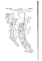
- FIG. l l have shown in section an assembly of elements, including a source of molten metal, such as the ladle i5, a receptacle for such metal, such as the receptacle E, and a rigid annulus 4U, which is provided with a 'specially cooled heat absorbing surface Il, onto ⁇ which molten metal is delivered bythe nozzle 5, forming a part of the receptacle G.
- the annulus 40 is shown broken away for convenience of illustration Aand is shown as suspended on driving roll 44, the axis of which is located within the vertical plane defined by the geometric and rotational axis of the annulus. In. this respect the view is illustrative only and is intended to disclose that the annulus is so mounted and so driven that it is free to expand in all directions.
- the annulus must be so designed'that the centrifugal force resulting from its rotation at the desired speed will not'be the predominating force durasistir heat absorbing surface where that surface is clean at the time the molten metal is delivered thereto and is so moved as to avoid taxs or vibratory forces. It has also been observed that this adsolidiilcation the centrifugal force freely lifts the continuously forming strip away from the heat absorbing surface if that force exceeds one pound per pound.
- the object of employing a heat absorbing surface-whether cylindrical or plane-is (l) to transform the stream of molten material, such as moten metal, into a hydrostatically self-leveling nlm of definite width and thickness; (2) to cool and chill this illm into a solid fiat product; and (3) to reduce the temperature of the solid film-like product to such a point below the solidiflcation temperature as will facilitate delivery, collection, etc.
- the peripheral speed of the ⁇ heat absorbing lcylindrical surface is preferably such that the lift the thin molten metal film away fromthe resulting centrifugal force, acting on the solidifled product, is less than one pound per pound of film.
- the kapparatus can be so designed that a larger quantity of heat may be absorbed through the heat absorbing surface and by the heat absorbing material on which the surface is formed, without raising that material to such a temperature as will occasion erosion, mechanical distortion, heat cracking or pitting.
- the annulus, or at least the heat absorbing portion thereof, ⁇ must be formed of high. conductivity metal, such as copper, and its thickness mustbe such that no portion thereof will be raised above injurious temperature during the procedure of absorbing heat from the molten metal deliveredthereto.
- the chilling plate can be water jacketed as shown an thus produce a convenient way of dissipating heat delivered thereto.
- an inner surface of the annulus may be employed as the heatabsorbing surface and under such conditions the centrifugal force occasioned by the Yrotation of the annulus will favor the procedure and consequently need not be controlled as before stated.
- Fig. is a diagrammatic view of apparatus somewhat similar to the apparatus disclosed in Fig. 4. It, however, diagrammatically discloses means for subjecting the layer or lm oi molten metal to a 'formative force after. it has been formed on the .surfaceof the heat absorbing annulus or chilling plate '40.
- the heat absorbing element 40 is of annular form and is so associated with a receptacle 6 and its delivery nozzle 5 that molten metal is laid onto the outer cylindrical surface 4l thereof, all as described in connection with Fig. 4.
- the annulus lll] is rotating at a high speed and theadhesive andA
- the roller 35a of Fig. 5 corresponds in structure and function to the roller 36.0f Fig.
- roller 3 is preferably water cooled as described in connection with the roller 35 so that it functions not only to exert a-forming force on the film-like layer but also to absorb heat from the layer.
- This adjustment oi" the position of the roller 33 peripherally of the annulus is accomplished by means, such as the set screws 4l iorming ya part of the apparatus diagrammatically illustrated in Fig. 5.
- roller 35a is so rotated that its peripheral velocityequals that of the annulus 40 and that the roller r36a may be adjusted to different positions radially of the annulus so as to vary the extent of the forming force applied to the nlm-like layer carried by the surface IH.
- Fig. 5 I have shown such an axial adjustment of the roller 35a as to appreciably reduce the section of the nlm-like layer as it passes under the roll or through the Working pass formed by the cooperation of the annulus 60 and the roll.
- rollers 48 each of which is diagrammatically shown as trunnioned in a prong-shaped rame 49.
- Each frame G9 is indicated as pivotally mounted ona iulcrum shaft 5l suitably carried by the frame of the apparatus and so arranged that each roller 48 is forced against the surface of the filmlike strip passing under it.
- the rollers 48 may be of such weight or may be so arranged that one or more of them subjects the then formed hot metallic strip to a substantial deiorming force, but I prefer to so adjust the rollers 48 that the force exerted by each and the results accomplished thereby are similar to the force employed and the results accomplished in the usual planishing pass employed in rolling mill practice.
- each infinitesimal section of the lm-like layer moves through a relatively short arc around the center of rotation of the annulus 4U, while passing from the highly ⁇ liquid-to the state at which it spontaneously crystallizes.
- the extent of this arc may be calculated more or less closely.
- V may be desirable to so position the roller 36 or 36a that its surface does contact with molten metal.
- the wetting action involves adhesive and cohesive forces but, as previously stated, the roller is rotated at a relatively high speed, consequently the centrifugal force prevents any portion of the metal from sticking to the roller.
- contractive forces tend to and do free it from its contactual gripping engagement with the annulus ,49, consequently it may be readily lifted from the heat absorbing surface and delivered as a continuously forming strip or sheet to a roller table or similar support. These contractive forces may also play some part in preventing the molten metal from adhering to the roller 36a when that roller is adjusted to such a posiguished from plastic, metal.
- Fig. 5 I have diagrammatically illustrated the hood 23 as enclosing the roller 36a and also each of the rollers t8. My intent is to disclose that my improved process contemplates employing the desired atmosphere during those portions of the procedure in'which a selected or controlled atmosphere may be beneficially employed.
- Fig. 7 is likewise a diagrammatic view of apparatus which may be employed in carrying out Under these conditions the roller plays my invention.
- the heat absorbing annulus 461s shown broken away for convenience of illustration.
- It is associated with a receptacle 6d, which, like the receptacle 6 of Fig. 2 or Fig. 3, is provided with a metering valve 28a, so arranged that it may be adjusted toward and away from the stationary bottom wall' 5.2 of the nozzle and may also be driven at a predetermined speed for the purpose of aiding in the delivery of, or of actually propelling molten metal from the receptacle 6a and onto the heat absorbing element 40.
- the feeding receptacle 6a is associated with a support shelf 53 forming a part of the frame of the machine and provided withfree running rollers 55 and a single roller 56 for supporting the receptacle in different positions thereon.
- the single roller 56 is so located that when the receptacle 6a is filled withmolten metal and is moved to an operative position, with relation to the annulus 40, it will be so supported on the roller 56 that it will balance toward the ring or annulus 40 causing the tip of the lower wall 52 of the metal delivery nozzle 5 to rub on the heat absorbing face of the annulus with a slight pressure.
- Fig. 6 I have indicated that .the point of initial contact of the molten metal, issuing from the-nozzle 5', with the heat absorbing annulus 40 is substantially removed from the vertical axial plane of the annulus.
- the distance between this point and such plane, or the vertical diameter of the annulus is indicated by the letter thus disclosing that the adhesive and cohesive forces involved cause the molten metal to move, with the supporting, heat-absorbing surface of the annulus, and even though the initial movement is an upward movement.
- the distance x is not a fixed distance, but is to some extent determined by the desirability of so positioning the molten metal delivery nozzle, with relation to the annulus, that the stream of molten metal issuing therefrom will be laid upon the rapidly moving peripheral surface of the annulus d with minimum impact and turbulence.
- Fig. 'l I have shown the heat absorbing .annulus or chilling ring 40 so mounted that it is not only capable of being rotated at the desired speed but also of properly cooperating with the molten-metal-feed receptacle 6 and of being free to expand and contract in response to the varying temperature conditions involved.
- the intent is to provide a heat absorbing annulus of such peripheral length that each heat absorbing portion thereof may be brought back to a preselected equalizing temperature of, for example, 300, 400 or 500 F. between the time that it moves free of the finished product and again receives molten metal from the metal delivery nozzle.
- the ring or annulus 40 will necessarily be of large diameter and this accentuates the necessity for permitting free and unhar'npered expansion and contraction while driving thering at the desired speed.
- each disc 51 is flanged as shown at 51' in Fig. 11 and is adapted to engage and support a re-entrant flange 6
- the two discs 51 fit the two flanges 6I of the annulus in the same way that the flanged wheels of a rail traversing a vehicle nt the rails constituting the track, and the flanges 51 of the discs therefore laterally position the annulus.
- the frame 64 is illustrated as substantially triangular. of discs 62 is journaled in a bearing 65 (preferably a roller bearing) located at one end of the base of the triangular frame 64.
- a bearing 65 preferably a roller bearing
- a similar construction and bearing is employed for the pair of discs 63 and the bearing 65', forming a part of that assembly, is mounted at the other end of the base portion of the frame.
- An apex hub 66 is secured to the lateral members of the frame 64 and is so formed that it receives a key shaft 61 rigidly secured to and dependingfrom the shelf 60. This key shaft extends vertically and the apex hub is apertured to receive it.
- the relationship between the apex hub 66 and the shaft 61 is such that the hub is capable of sliding freely along the shaft, but is prevented from turning around the shaft.
- the frame 64 is also provided with a, base hub 68, which is secured to the base member ofthe triangular frame at a point midway between the bearings 65 and 65'.
- the base hub is apertured to receive an upwardly projecting shaft 69, which, as shown in Fig. 1l, is rigidly secured to a bracket 69 of the main frame of the machine and is axially aligned with the key shaft 61.
- the shaft 69 is also a key shaft and the relationship between it and base hub 66 is such that the hub is capable of sliding freely alongthe shaft but is prevented from turning around it.
- the weight of the frame 64 is substantially counterbalanced by weights 16 acting through a counterbalancing lever 1I, which is fulcrumed on a bracket 12 of the frame and is forked to provide a bifurcated end 13, which straddles an extended
- a reference to lFig.'10 discloses that the centerless ring or annulus 48.
- ls of H-section i. e., the web portion 48a is provided with outwardly projecting flanges 15, as well as the re-entrant flanges 6
- Theflanges 15 define the width of the heat-absorbing, molten-metalreceiving surface of the annulus 48 and while they are shown formed as a. unitary part of the annulus, it is apparent that theymay be. separately formed and so arrangedthat they may be adjusted toward and away from each other so as to vary the effective width of this heat-absorbing surface.
- Fig. 10 also discloses a convenient and desirable way of providing the web 48a with a water jacket or chamber 42 through which water or other coolant may be circulated.
- the annulusl is provided with an annular band of corrugated metal 16, which is fitted between andl secured to the flanges 6
- the lateral edges of the band are flanged and each such flanged edge is secured to one ofthe flanges 6
- this is accomplished by securing the flangedends of the corrugated band 16 to the flanges 6
- Figs. l0 and 11 I have shown the inner face -of the web 48a corrugated-i, e., provided with alternately arranged circumferentlally extending grooves and ridges 18-for the purpose of providing an extended surface exposed to the coolant within lthe water jacket or chamber 42'.
- Figs'. 7, 8 and 1l I have illustrated means for obtaining a circulation of coolant through the chamber 42.
- the annulus 48 is provided with a manifold 19, to which a. delivery pipe 88 is connected.
- the pipe 88 is also connected'to an elbow 8
- a water delivery pipe 82 (Fig.
- the annulus communicates with this elbow and is so connected to a source of waterunder pressure that it is capable of turning with the annulus, but at the same time supplying water to the chamber 42' through the inlet ppe 88.
- the annulus is also provided with an outlet manifold 83 and similar piping connections are associated with it so as to maintain a circulation throughout the annulus during its rotation.
- inlet manifold I9 is separated from the outletA manifold 83 by a partition 84, which may extend entirely across the chamber 42.
- An outlet pipe 85 communicates with and is secured to the outlet ⁇ manifold v83 and is connected by suitable pipe connections 85-85' with a discharge pipe 86 (Fig. l1) ⁇ which is located centrally and extends axially of the annulus 48.
- centerless gear I mean 'one in the form of an annulus or ring and devoid of spokes and hub or equivalent structure.
- 'I'he ring gear 98 has a pitch diameter substantially equal to the diameter of the heat-absorbing cylindrical surface 4
- the inner surface is provided with an annular ridge 9
- the ring gear is supported by three spaced rollers 92, 93 and 94.
- the roller 92 is mounted on the shaft 58 of the roller bearing 59 and, like the other rollers 93 and 94, is peripherally grooved to receive the ridge or track 9
- the rollers 93 and 94 are mounted on either side of the roller 92 and the threezrollers are located in triangular relationship and in such ⁇ positions, with relation to the circumferential track 9
- Each of the rollers 93 andv 94 is provided with a separate mounting shaft which is journaled in a separate bearingsupported on and rigidly secured to the shelf 68 forming a part of the machine frame.
- the ring gear 98 is provided with a three point support, thus definitely defining its position.
- 'I'he gear 98 is driven by a motor 95, which is preferably of the variable speed type and is shown mounted on the shelf 68 of the frame.
- the shaft 95 of the motor is provided with a pinion 96, which meshes with and drives a gear 91, carried by a shaft 98 which also carries 'a pinion 99, which meshes with the teeth of the ring gear 98.
- the shaft 98 is mounted in a suitable bearing supported by a vertical Wall
- the pinion 99 meshes with the teeth of the ring fgear and drives that gear.
- the ring gear 98 is provided with a. plurality of laterally projecting pins
- the ring gear is provided with six such pins, each being threaded into an aperture provided for its reception and projecting laterally of the ring gear.
- 83 may be formed ,as an integral partof the annulus 48 and, as shown, each projects laterally from the section and dimensions as to provide a rigid support for the'annulus, the ring gear and accessories.
- it is a cast structure and is, of course, intended to be rigidly secured to an adequate and rigid fundation. It consists essentiallyof a vertical wall member
- Fig. 8 is a more or less diagrammatic eleva' tion of the annulus I0, together with accessory apparatus; For convenience of illustration, a portion only of the machine frame is illustrated but it will be understood that the vertical wall portion of the frame is located in such relationi ship to the annulus 40 and the ring gear 90 that both may be rotatedat high speeds without being subjected to substantial vibration, side sway,
- Fig. 8 I have disclosed the molten metal feed receptacle 8 as provided with a separately formed removable delivery nozzle
- 05 is shown bolted to the metal casing of the receptacle 6 and a reference to previously described illustrations will make it.
- metering alve I 06 is in effect a water cooled roll provided with hollow trunnions
- 06 is shown as formed in' three parts, viz., a cylindrical part
- Each such hub portion is peripherally flanged to receive the cylindrical portion
- 06' is adapted to be included in a water circulating system for the chamber III and is, therefore, provided at its outer end with an ordinary fitting I I2 which is secured thereto by means of la suitable packing gland' nut
- cooling water or medium may be dey livered to the trunnion
- Radial passages Ilii provide a means of communication between the interior of the trunnion and the chamber II I.
- Similar passages IM' are provided in the hubder such conditions, it will be vdesirable to continuously dissipate-the heat absorbed by the metallic surface and this, of course, will be accomplished by providing a suillicent-circulation of cooling medium through the chamber
- the molten'metal contacting surface ofI the metering valve may be such as will be Wet by the molten metal, but this surface is preferably oxidized or otherwise coated so as to prevent adhesion or sticking of the molten metal.
- 01 is car-- ried by the vertical wall portion
- This adjustment is accomplished by providing an adjustable abutment IIS for the free end of the fulcrumed frame
- this l means consists of a crank cam IIB which is car-' ried by a crank shaft
- This crank shaft is geared to a counterweight spool
- is so supported by the spool
- crank shaft II'I may be employed for the purpose of lifting the frame 01 and thus moving the metering valve to an inoperative position 'with irelation to the annulus 40.
- 06 is provided with a driving gear
- any suitable means may be employed for driving the metering valve and its position, with relation to the molten metal delivery nozzle, may be such as heretofore described, particularly in connection with Fig. 3.
Description
J. M. MERLE May 2, 1944.
METHOD 0F MAKING METALLIC PRODUCT OF SHEET-LIKE FORM 7 Sheets-Sheet 1 Filed Nov. 5, 1937 INV EN TOR. 777. m BY/W #mem L, ATToRNEYs.
J. M. MRLE May 2, 1944.
METHOD oF MAKING METALLIC PRODUCT oF SHEET-LIKE FORM '7 sheets-sheet 2 Filed Nov. 5, 1937 IN VEN TOR.
V/'J ATTORNEYS.
J. M. MERLE May 2, 1944.
METHOD oF MAKING METALLIC PRODUCT oF SHEET-LIKE FORM Filed Nov. 3, 193;'
7 Sheets-Sheet 5 INVENToR.
7??. Wie/bez., i2? T M ATTORNEYS.
LIKE FORM J. M. MERLE May 2, 1944.
METHOD GF' MAKING ETAL-LIC PRODUCT OF SHEET- Filed Nov. 5, 1937 7 Sheets-Sheet 4 INVENTOR.
/LWO
QZ/; ATTORNEYS J. M. MERLE May 2, 1944.
METHOD OF MAKING METALLIC PRODUCT OF SHEET-LIKE FORM Filed Nov. 3, 1937 7 Sheets-Sheet 5 IN VEN TOR. W m 7M /L www 61 Q m@ A #a ATTORNEYS.
vMany 2, 1944. J. M. MERLE 2,348,178
METHOD 0F MAKING METALLIC PRODUCT OF SHEET-LIKE FORM Filed Nov. 3, 1957 '7 Shees--Sheel 6 70 INVENToR.
Wm www ATTORNEYS.
J. M. MERLE May 2,\ 1944.
METHOD OF MAKING METALLIC PRODUCT OF SHEET-LIKE FORM Filed Nov. 3, 1937 '7 SheetSSheet IN V EN TOR.
L ATTORNEYS.
Pciccic'd May z, 1944v UNiTED- s'i'A'rEsl MErnon or MAKING Mamme Paonuc'rs or. simn'rmxir roam Joseph M. Merle, Tarentum, Pa. Application November a, 1931, scrici Nc. 172,516
. 5 Claims.
This invention relates to a new methodoirv making a new product, namely, a metallic product in sheet or strip form.
An object of my invention is to provide a. commercial procedurel for manufacturing-'metallic strip which is simpler and more effective than any procedure heretofore employed commercially and which involvesl forming sheet or stripflikel l product .direct from molten metal without the necessity of employing intermediate steps such l0 as the usual casting and rolling procedures.
There have been numerous attempts to form flat metallic products direct from molten metal,
but all such attempts have either resulted in complete failure or haveresulted in procedures 15 of vdoubtful commercial Dracticability, botli'from the standpoint ofthe procedure itself and also from .the standpoint ofthe productv resulting therefrom,
. One such procedure was suggested as early as 20 1865 and, as disclosed by Bessemer Patent 49,053 of 1865, involves providing a pool of molten metal inthe `crotch between two cooled rolls and ro-v tating the rollsiin opposite directions and in sucha'way as to discharge downwardly and through 25 the space between therolls, such solidied metal as may form within the pool and to mechanically deform it into a iiat product as it is so discharged. The records in the United States Patent Ofllcedisclose that variations of this' pro- 30 cedure have been periodically attempted, but the commercial art discloses that uch attemptshave only met with mediocre succ and then in connection with metals of low melting points.
In carrying out my invention, I take advantage 35 of natural physical phenomena or laws not heretofore utilized in previous attempts to form sheet or -strip-like material direct from molten metal, and as a result I not only produce a product having highly advantageous and novel physical char- 40 acteristics, but I also produce a procedure which vis simple and effective and is capable of lbeing effectively employed commercially. -v
A metal in the molten state acts like most other liquids. It exhibits the physical ehm-m- 4l' terlstic of surface tensioninvarying degrees and dependent somewhat upon the particular metal l and its temperature, but its principal characteristics, at ordinary industrial pouring temperatures, are its liquid-like 'free mobility4 resulting 'from the reduced cohesive forc between its atomic or molecular constituents;l its ability to readily shape itself in response to applied orfconiining forces; its ability to wet most materials (Cl. zit-200.1)
vself-levcuiig characteristic under uniformly cpplied forces such as gravity or other ydirectional forces. My new method takes advantage of such inherent ,physical characteristics as are exhibited by molten metal at ordinary industrial pouring temperatures and involves utilizing those vcharacteristics in the productionof a liquid layer of controlled width and thickness and in then cooling 'the same to the solidilication temperature, and delivering the solid continuous nat or sheet-like product so formed.
My new method broadly consists in creating controlled ilow of molten metal existing ata predetermined temperature, such, for example, as the ordinary industrial pouring temperature, andl v in interceptlng the flow with an extended, clean,
cold surface of a heat absorbing agentl capable of being wet by the molten metal and moving at a uniform rate in the direction of its extended surface and at a velocity-greater than the velocity of flow of the metal, whereby the molten metal v is, in effect, delivered-to the moving surface,
coats that surface -or a portion thereof by rea- ^son of its; wetting action, i. e., its capacity to adhere toy such surface, and builds up a layer thickness thereon in response to interatomic or intramolecular forces-i. e., cohesion forceslanti 'to an extent -which is dependent upon theA )relative velocity'of the heatabsorbing surface and the velocity of flow of the molten metal stream, and then chilling the metal of thisiayer to the solid state while it 'is in-contact withv and in fact supported by the surface lof such heat absorbing element. i
My invention also involves new and improved apparatus for continuously producing strip from p molten metal, such las steel, and'while I have illustrated various modifications oi.' such appaf ratus, each such embodiment is so formed that it is capable of carrying forward more or less speciilc procedure which involves creating-a substantially uniform flow of molten metal in the form of aconilned stream; laying such stream on a substantially horizontally disposed, rapidly .moving heat absorbing surface capable of being wet by the molten metal; accomplishing the delivery of the molten metal to such surface so as to eliminate the effect of the turbulence inthe stream at the point of initial contact between molten metal and 4heat abmrbing surface; and
accumulating on 'such surface a molten layer by reason of the cohesive and adhesive forces there involved,vcooling the layer so formed below the solidiilcation temperature. and then delivering with which it is brought into contact; audits Ill the layerin the form of a contimious strip while nietig-aire utilizing the contractive and expansive force encountered to free it from the heat absorbing element.
I have discovered that where molten metal such,` for example, as ferrous metal, is so delivered to such asurface the quiescent stream continuously supplied onto the moving surface will be drawn out into a layer moving at the velocity of the surface and accumulated by combined adhesive and cohesive forces from metal below the i major portion of the surface of such tream.
The metal of the layer is self-leveling hydrostatically while still molten and highly plastic but is rapidly chilled by reason of its extended surface, and is converted into a solid strip of substantially uniform width and thickness which is first carried by the absorbing surfacoby reason of the gripping contact between it and the surface, but which shrinks as it cools and is thus freed from the supporting and cooling surface without any interfering factors.
The width of the strip so formed can be controlled by controlling the width of the molten metal stream as it is delivered to the heat absorbing surface and I have discovered that the thickness of the strip may be controlled within close limits by controlling the relationship be- Vtween the velocity of the absorbing surfae and the velocity of ilow of the molten stream delivered thereto. To state this in another way, the cross section of the metal strip is determined and controlled within close limits, by the following relation: Cross sectional area of the strip multiplied by the velocityof the heat absorbing surface equals the cross sectional areav of the molten streamqielivered to the surface) multiplied by the `velocity of thel flow of that stream. g
For example, if the stream of molten metal flowing from a rectangular nozzle 2 inches wide and one-half inch thick, and at a velocity of two feet per second is delivered to and laid upon a heat absorbing surface, such as previously described, moving at 50 feet per second, the section of the resulting continuous strip can be computed as follows: Z %O=.04 square inch. That is to say, the metal layer or strip formed will-have a cross sectional area, of 0.04 square inch. I have also discovered that where a nozzle, such as above described, delivers molten metal to such a heat absorbing surface under conditions such that there is little or no turbu ience at the zone of initial contact between the stream and the heat absorbing surface, the width of the resulting layer and strip will be substantially that of the nozzle, consequently in the above example the gage of the strip or film will be .04 divided by 2 or .020 inch.
While the procedure for forming the continuous strip may be varied, it will be apparent from the foregoing that the now preferred procedure not only involves the utilization of all surface and the molten metal'delivered thereto. This i'orce is of considerable magnitude, even though other forces may be involved, and can account for the fact that the molten layer adheres to the moving heat absorbing surface and acts as a unitary part of that surface-i. e., moving with it at the same speed and in the same directionup to the pointwhere it loses the adhesive and `vacuum grip by its complete solidication and subsequent shrinkage under the cooling or chilling conditionsencountered.
It will, of course, be apparent that even after the metal strip is thus freed from the moving heat absorbing surface it will continue to move in the direction of and in response to the impelling forces previously acting on it.
Wliile the layer of molten metal is adhering to and moving with the heat absorbing surface, the absolute contact between the metal and the surface makes it possible to consider the twoas a single bi-metallic section in determining heat exchange conditions. The heat exchange between the molten layer and the solidor heatabsorbing layer and throughout their respective thicknesses is directly proportional to the heat conductivity of each layer and the heat gradient involved, consequently the above known factors make it possible to determine the length of time that contact must be maintained between ythe two layers in order to solidify the molten layer and free it from the heat absorbing layer. That the,forces heretofore enumerated, but also selecting a heat absorbing surface whichis wetted by the particular molten metal acted upon. lit may be that .further investigation will disclosel variations in the capacity of a molten metal to wet different solid materials, but I have found that most molten metals, including alloys, when delivered to a clean," cold, dry surface of solid material, such as steel or copper or 4a copper alloy, provide good contact between the molten lmetal and the surface due, no doubt, to the wetting action or the free action of interatomic :attraction between the metal of the absorbing is to say, the heat transfer which takes place is tallic layer and a determined section of a se@ lected heat absorbing material, consequentlythe desired velocity of the heat absorbingtsurfaco having been selected, the distance through which the combined or bi-metallic section must movein order to obtain the desired vcooling of the molten metal layer-can be mathematically determined.
While I have stated that the thickness of the molten metal layer, and consequentlyI of `the nnished strip, can, in eifect, be controlled by controlling the relationship between the velocity of the moving surface and the velocity of flow of the molten stream delivered to that surface. this statement is accurate only, so far as I now know. for thickness up to about V4", as other factors may aifect the exact relationship when molten metal layers of larger thickness are involved.' The foregoing. however, discloses that the known factors available make it pomble to accurately determine the amount and rate of heat dissipation necessary in order to accomplish the dosired results, and that the various facilitiesopen to the designer oi' apparatus fol-*carrying out theprocedure-make it posible to not only effectively dissipate the heat of the molten metal,
lng elementis properly selected, with relaon to the capacity of the molten Vmetal to wet it, the contact between the molten metal and-tbe Supasians porting surface of the heat absorbing element is so intimate that a vacuum grip is accomplished and the surface of the heat absorbing element is, in effect. reproduced upon the formed strip. For this reason it is not only possible but desirable to provide theheat absorbing element with a polished heat absorbing surface and to. then so correlate heat input and heat dissipation from that surface as to avoid temperature condltions which will even tend to corrode or mar it.
The procedure herein defined also results in the production of a strip having improved physical characteristics. It is apparent from theforegoingdescription that my improved process involves dissipatng substantially al1 heat-i. e., the superheat of fusion and the latent' heat of fusion-while the metal being processed is in layer-likeform of the-thickness of the nished product. l As the moving heat-absorbing surface contacts with the molten metal, it almost instantaneously draws that metal out into a thin sheet o f the desired finished thickness and, as a result, substantially all the cooling takes method is similar in physical characteristics to the chilled layer and is characterized by a primary. crystal structure freeA from separate or' distinct zones or layers of crystallization and homogeneous and uniform throughout the length and thickness of the strip. 'l'hat is to say, the product of my improved procedure is characterized by minute stringer-like crystals at random,l and all substantially identical in size and uniformly and homogeneously distributed throughout the mass of the finished product. In addition, thevstrip-like product is characterized by .a uniformity of chemical composition identical to that of the molten metal supplied by the melting furnace and free from variations and defects, such as are inherited from a primary ingot structure and as are occasioned byv selective segregation of component metals and concentration of impurities at the grain boundaries of columna'l crystals, gaspockets, etc.
'Ille material is also free from the directional effect such as is ordinarily occasioned by mechanical working and crushing of the large place under conditions such that heat is not only rapidly delivered to the relatively cold heatabsorbing velement but-also while the metal, being so cooled, exists in layer-like form.
It is generally acknowledged that the Acast structure of metals is weak as compared to such structure as is developed by or results from -mechanical' working, and that this inherent weakness is due'to the typical crystal formation. obtaining in a cast product which has zones or layers of. crystallization as follows: l. A chilled layer or skin at the periphery of the castingl and made up of small stringer-like at random not oriented) crystals.
2. A layer of long columnar crystals also called4 dendritic crystals which characterize ingpt and other Acast-formations. This new product,how everfrgtains most of the above-described characteristics and advantages of its new primary crystalline structure after mechanical working,
such as rolling, forging or extrusion and after heat treatment to which it responds effectively and actively, due to-its uniformity and homogeneity. A
'This crystalline structure of this improved product' and the physical properties resulting dendrites or needles, oriented with respect to 'I the axis of crystalline growth and in a direction opposite to heat flow and which 'is the main cause of the cast structural weakness.
3. A central zone of equiaxed large crystals. The physical properties of theA above mentioned chilled layer are usuallyvmuch better than the properties of other parts of the casting and of the ilnished product after the casting hasv been subjected to mechanical working, because its chemical composition is homogeneous and free of segregation andin this respect is the same as the molten 'metal in the furnace or ladle. 0n the other hand. the heterogeneous crystalline structure of the casting is characterized by selec- Vtive segregation of the alloy and impurities, gas
pockets, shrinkagecavities or piping and other well known phenomena defined under the general name of ingotism.
Y Recent research and investigation, in Aconnection with the crystallization of metals, has shown that the at random, fine crystalline structure of the chilled layer of an ingot is due to the substantially instantaneous undercooling of a thin shell of molten metal as it contacts with the cold walls'of the mold, and the resultant. practically, spontaneous crystallization within that! shell which is free from segregation and orientation. It has beenfound thatthe sectionof the crystals in the chilled layer becomes smaller as the velocityof crystallization increasesi. e., as the timefactor decreases. I not only utilize these discoveries in producing the product here deflned-but'alsoincontrolling the size of such 4 crystals` and 'the relative iinenessof the material` From the foregoing it will berapparent that therefrom are particularly marked in high alloys. such as high speed tool steels, and the so called stainless irons and steels. In addition, it will be apparent that the procedure is such as to almost wholly eliminate defects and disadvantages occasioned by gases occluded of in solution in the molten metal.
t From the foregoing it is apparent that an object of my invention is to provide new'and improved apparatus for producing strip direct `from molten metal. r
A further object is to produce flat metallic material, such as strip, having new and improved physical properties and characteristics.
These and other objects which will be made more apparent'throughout the further descrip'- tion, are. attained by means of the apparatus herein 'disclosed and the procedure or method described in connection therewith.
In the drawings,
Figure l is a diagrammatic vertical sectional view ofY a machine embodying my invention andv in which the improved molten metal is deliv ered tothe surface of a rapidly moving heat absorbing element in the form of ran endless belt;
Fig. 2 is a vertical sectional view, on an en larged scale, and illustrates a modication of a A structural detail of the machine shown in Fig. 1:
Fig. 3 is a view corresponding to Fig. 2 but diagrammatically illustrating a forming roll in such relationship tothe associatedv parts that it coactswith the heat absorbing element in the production of the ilnished product; Y
Fig. 4 is a diagrammatic, sectional view of modified form of apparatus in which the heat absorbing element is in the form of a rigid annulus,
I such as a ring or cylinder;
the metal product ,produced by my improved 75 Fig. -5 is a diagrammatic, fragmental, lsectional view of a machine similar to the machine cf Fig. 4 but illustratingstructural-variations;
i nuria, 17s
iiig. 6 is a side elevation of a machine, such as is generally illustrated in Fig. 4 or `iiig. 5;
Fig. 7 is a fragmental, sectional view of a machine, such as is illustrated in Fig. ll, but equipped with a rotary metering valve;
Fig. 8 is a view in side and sectional elevation of a ring type machine equipped with structural features similar to those illustrated in preceding views;
Fig. 9 is a diagrammatic view illustrating the gearing employed in connection with the machine of Fig. 8;
Fig. 10 is a iragmental, transverse, sectional view of a water jacketed strip forming ring and illustrates means for driving the ring;
Fig. 11 is a vertical, sectional view of the machine diagrammatically illustrated in Fig. 8;
` Fig. l2 is a diagrammatic top plan view of the machine shown inFig. 8; and
Fig. 13 is a diagrammatic, fragmental, sectional view of apparatus such as disclosed in Fig. 8 and illustrates accessories which may be employed in connection therewith.
Fig. l is a diagrammatic illustration oi a simple but effective machine for carrying out my new process. There the heat absorbing agent is in the form of an endless belt or band, preferably made from metal having high heat conductivity, such,
for example, as copper, silver, copper' alloy, bronze, aluminum, etc. The belt is so mounted that one strand or reach is not only substantially horizontal, but is also substantially fiat and is adapted to receive molten metal delivered from an associated nozzle. 'I'he arrangementis also such that a stream of molten metal of controlled width, flow and temperature is, in e'ect. laid upon the belt while the belt is moving at a uniform rate in the general direction of stream ilow and at a velocity such that the stream is drawn out into a layer of the desired thickness o1' the ilnished product. The continuous stream of metal is so laid upon the moving belt as to substantially eliminate turbulence but at the same time create a continuous and controlled flow on the belt so that the finished product can be produced in continuous or strip-like form.
'I'he heat absorbing belt is so constructed with relation to heat absorbing. ability and is so positioned, with relation to the molten metal delivery nozzle, and is so cooled that itis capable ol' chilling the metal contacting therewith to the solidiflcation temperature while such metal is retained ilat, and all without raising the temperature of the belt above a safe and predetermined temperature. That is to say, the belt is so constructed and proportioned with relation to its heat absorbing capacity and available cooling facilities that the temperature thereof is nover raised to such a point as to occasion welding, surface pitting, cracking or erosion, or the warping of the belt. In addition. the belt and its supports are so positioned, relatively to the molten metal delivery nozzle, that the time of contact between each portion of the belt and the metal supported thereby is sufilcient to not only insure solidiflcation of the molten metal, but also its free release from the belt under such conditions that it will be propelled. by the forces previously acting on it, in substantially the direction of its travel while in gripping contact with the beit.
Referring specifically to Fig. l, aA heat absorbing, element I, in the form of an endless belt, is mounted on spaced pulleys 2 and 3, which are suitably Journaled on a frame l including a table la. The pidiera 2 and 3 are so located, within relation to each other, that the'upper reach or leg of the belt is substantially horizontal and is located immediately above the table la. A nomic 5, for delivering molten metal onto the upper reach of the belt, is shown formed as a part of a molten metal receptacle 6, which is mounted on the machine frame and is adjustable therealong and lengthwise of the upper reach of the belt I.
Any suitable means may be employed tor driving the belt, consequently .I merely note that the pulley 2 is mounted on shaft I and that the shaft 'I isa driving shaft which may be, and preferably is motivated by a motor, the speed of `which may be adjusted. In order to maintain the upper. reach of the belt horizontal and also ilat, i. e., substantially in one plane, I employ means for taking up the slack in the belt and this means is illustrated as a hydraulic cylinder I carried by the frame l and provided with a piston 9 operatively connected to the bearing block of the pulley 3. The cylinder is shown as provided with an inlet port I0 through winch liqui d under pressure is admitted. In addition to this yielding means for taking up the'slack in the belt, I. also provide grooved guides I I mounted on the machine frame and each adapted to receive one lateral edge of the upper reach oi' the belt I as the belt leaves the pulley 3 and moves across the table la and onto the pulley 2.
As shown, the delivery end, of the nozzle 5 is located immediately above the upper reach of the belt and at a point intermediate the pulleys 2 and I. The receptacle l is shown as provided with a refractory lining and is divided into two compartments I2 and Il', which communicate with each other through a continuously submerged port Il. 'Ihe compartment I3 communicates directly with the nozzle I and is preferably of substantially greater capacity than the compartment I2, which is adapted to receive molten metal direct from a furnace or ladle. In the drawings, I have shown a diagrammatic representation of a ladle I5 so suspended that its pouring apparatus Il is delivering molten metal into the compartment I2. With this arrangement, slag and other impurities tend to float to the top of the metal within the compartment I2,
whereas clean metal enters the compartment I3 through the submerged port Il and isy available tor delivery through the nozzle I.
The belt I is so driven by the pulley 2 that it moves in the direction of the arrows-of Fig. 1 and its upper reach, therefore, moves in the generalI direction of the ilow of metal through the nozzle 5 and onto it.. a
Various means may be employed for cooling the belt I and in the drawings I have illustrated means for spraying cooling medium, such as liquid, onto the lower leg or reach of the belt. As there illustrated, the cooling means includes a liquid delivery pipe I1, which communicates with and supplies cooling medium to spray pipes Il, which extend along and below the lower reach of the belt and are provided with spray apertures', for directing cooling medium on the lower sur-y lace of the belt. One or more rubber. squeegees I9 are so mounted on the machine frame that they bear on the belt I at a point beyond the delivery of coolant thereto so that all traces of coolant are wiped oil' of the surface of the belt as it moves toward and onto the pulley 3. As shown, the squeegees are located within the confines oi' a tank 20, which extends throughout the length of the belt, is located below ilo-e spray pipes IB and is adapted to receive the coolant issuing therefrom and dripping from thebelt. The tank is Provided with a drain port '20"iand if desired ordinary and well knownI means may be employed for recirculating the coolant collected within the In Fig. 1 I have shown the machine provided with a product-receiving table 2| and an extension thereof in the form of4 an arm 22, which is hinged on the machine frame in such-position that its free end inayvbea'r on the belt I as it moves around the pulley 2. In addition, the arm 22 is so formed that its upper face-i. e., its product-receiving and directing facelies within or just below the plane defined by the upper reach of the belt.
I have also shown theapparatus of Fig. 1 as provided with a protective hood 22 for the pur- .pose of preventing oxidation of the holten metal as it is delivered onto and moves with the belt I. As there illustrated, the hood is in the form of a shield which encloses a portion of the upper reach of the belt and which is secured to the receptacle 6 or the portion thereof which deilnes the nozzle-5. 'Ihe hood is provided with a gas delivery pipe 24 and may be provided with a gas discharge pipe 25. yThat is to say, the arrangement is such that ari/inert atmosphere may be maintained within t e hood by reason of the delivery thereto of an inert gas, such as hydrogen, nitrogen, ammonia fgas, etc.
The adjustment'of the receptacle 6 along, the belt may be accomplished in a number of more or less obvious ways and fonthis reason I have diagrammatically illustrated it as associated with an ordinary positioning screw l26, which is threaded Athrough a fixed or stationary bracket 2i' of the machine frame. Such an arrangement provides means for adjusting the position of the nozzle i along the upper reach of the belt and for locking l it in the adjusted position.
The operation of apparatus such'as described is as follows: Molten metal at a temperature, such as is ordinarily employed in commercial pouring,
is delivered to the compartment I2 of the recep- -tacle 8 and preferably under conditions such as to maintain a predetermined 1eve1 within that compartment.y This metal passes through the submerged port I4 -into the compartment Il,
which, as stated; Ais in open communication with the nozzle I. Thecompartment I3 ispreferably of such capacity as to minimize the effect of such variations in heady as may be occasioned by a lack of uniformity compartment I2. f ,c
The nozzle is so formed and located that the stream of molten metal issuing therefrom is delivered to the surface of the upper reach of the belt without producing undue stream so delivered is controlled as to width and rate of now. The width substantially corresponds to that of the nozzle and the ow responds to variations in head within compartment I3, i. el, the cross sectional area of the nozzle 5 and the head of molten metal within the compartment I2 controls the velocity of flow of the molten metal issuing from the nozzle and moving onto the belt.
'I'he foregoing discloses that the belt I is so driven that its upper reach is moving in the general direction of the metal flow during the entire period that metal -is issuing from the nozzle i. It will also be apparent that the velocity of the belt is suoli, with relationto the rate of metal in the delivery ofnmetal to the turbulence inthe ilow of metal onto the surface. In addition,.the
of predetermined width and thickness, i. e., the width and thickness of the finished product.-
One problem with apparatus, such as illustrated in Fig. 1, is to so position the nomle 5 with relation tothe upper reach of the belt I that the layer of metal distributed over the belt is not only cooled to the solidiflcation temperature, but also to such an extent that it is freed from the belt prior to the time that the belt moves around the pulley 2. This, however, can be computed with sufficient accuracy to assure the desired results. Assume', for example, that the machine of Fig. 1 is operating under conditions such as to produce a finished product the form of a strip 2" wide and .020" thick and that the delivery throat of the nozzle 5 is 2" x l/2" and delivers molten ifnetal to the belt I at the rate of 2 feet per second. The application of the previously mentioned mathematical equation discloses that the belt must be driven at a speed such that its linear velocity is 50 .feet per second. This Aalso means that the layer of molten metal (2" wide and .020" thick)4 adhering to the belt is moving at a velocity of 50 feet per second.-` The` designers specific problem is, therefore, to soY design the belt I-from the standpoint of material employed in its make-up, its length and also cooling facilities availablethat the metal supported on it is cooled to the desired temperature as it moves toword the pulley 2, and all withoutraising the belt or any portion thereof to such a temperature es wion 'permit weming or as will detrimentany effeqt the physical characteristics of the belt.
`The manskilled in the art will recognize that must be such as to dissipate the heat thus taken up by the belt, and to accomplish the dissipation during the period that the belt-is moving free of the molten metal or the nished product and this 'factor designates the length of the belt. That is to say, the belt I` must be so designed that it will accommodate the rapid dissipation of heat from the molten metal delivered to lit but it must also be so' designed that each unit of length thereof will, under the cooling facilities available, be cooledto a predetermined and constant temperature during the time it is moving free of molten or solidified metal. AIn other words, the belt must be so designed that each unit of length'thereof will be cooled to a predetermined temperature as itmoves around the pulley 2, throughout the -distance spanned by the lower reach of the belt, around the pulley 3 and back to the metal-receiving position below the `ness and the physical characteristics ofthe flow onto it, as to draw that ow out into a layer la metal, of which the belt is made, lwill determine the diameters of the pulleys 2 and I in order to avoid subjecting the belt to stresses beyond the elastic-limit as it moves around the pulleys. It
should, however, be noted that the diameter of the pulleys 2 and 3, orof equivalent structures, have no other influence on the working of the process here outlined, except where their belt in Fig. l. This length is variable and depends upon the ilnal or delivery temperature of the product, the initial temperature -of the molten. metal and the heat conducting conditions involved. It will also be apparent to those skilled in the art that under some conditions the majority of such length is required for the purpose vof cooling the metal to nal temperature after it has arrived at the solidiiicatioh ltemperature, i. e., a temperature such that the metal is no longer in the liquid stata I have heretofore stressed the necessity for vmaintainingthe belt ilat as it receives, forms and chills the molten metal. This because I conceive my process as involving procedure such that the molten metal is, in eiect, subjected to forming forces by the heat absorbing element, but must be cooled through the plastic range and into the solidiilcation range without being subjected to disrupting forces. For this reason it is necessary to so form and mount the pulleys 2 and 3,that during the operation of the process the molten-metal-receiving reach of the belt moves without vibration and under such conditions that its metal supporting surface moves in a plane defined by the direction oi' its motion, vwhile passing through length X, or such portion of such length as is required to accomplish the solidification of the molten metal.
As previously stated, the contact between the molten metal and the heat absorbing element is so intimate that the surface characteristics of the element are reproduced on the adjacent face of the nished strip-like product. Under some conditions it may, therefore, be desirable to provide the heat abrbing element with a polished surface and conditions may also makeit desirable to plate the surface ci the element with a metal having high heat conductivity or other desirable physical characteristics., For example, where conditions are such as tomake it desirable to provide a heat absorbing element having a l surface of high melting point, highly resistant to erosion and to liquid diusion, the heat absorbing element may be plated with such a metal as chromium and then polished to the desired degree of smoothness.' On the other hand, where conditions are such as to indicate the necessity for high heat conductivity at the surface of the heat absorbing'element, that element may then be plated with such metal as silver. Forcthis reason one detail oi my invention involves providing the heat absorbing element with a surface such as conditions designate and even where such a. surface is laidonto the element by a plating or other procedure.
The strip-like product produced, as above described, is chilled to such a temperature that it frees itself frm the beit without disrupting or f disturbing factors, prior to arriving at a. position with relation to the pulley 2, where the belt contacts with and starts to move around that pulley. 'I'he strip-like product will, therefore, move across the extension 22 and onto the table -2I from which it may be delivered to a coller or to other means for handling it.
.Where the hood 23 is employed, gas is clelivered thereto through the passage N during the entire product-forming operation. Ordinarily gas is selected so as to provide a neutral "5 or inert atmosphere, but the gas may be selected in order to promote a desired chemical reaction with the molten metal. Under such circumstances, a constant circulation of the gas is preferably maintained within the hood in order to insure continual effectiveness in connection withn the desired reaction and the passage 25 may therefore be employed as a part of the gas circulating system.
vIn Fig. 2 l have shown a modied form oi yit molten metal receptacle equipped with accessories which maybe employed in a machine, such as illustrated in Fig. 1.* As shown, the receptacle E' is provided with two compartments I2 and I3', which are adapted to be placed in communication with each other through a submerged port It. This port is provided in a horizontally disposed partition and is adapted to be controlled by a manually'adjustable stopper-1l". With such apparatus, flow through the nozzle E' can be controlled by adjusting the position of the stopper 21 with relation toits seat around the port 4 I4", or the flow can be completely cut oir by seating the stopper and thus closing thev port it.
.The previous description discloses that the molten metal delivered through the nozzle is drawn out into a metal stream or layer by the movement of the belt l and that the uniformity `of this layer depends, at least in part, upon uniformity of flow of the molten metal stream issuing from the nozzle 5. It is, of course, apparent that the velocity of such ilow will vary with variations in lthe gravity head and, it will also be apparent, that the confining walls of the nozzle and of the passage leading thereto, will cause retardation of the iiow in the portions of the stream immediately adjacent thereto. in order to insure a iiow of metal onto the belt which is substan- Y tially uniform throughout all portions of' the stream. I have provided what may be termed a metering valve 2E, which is diagrammatically shown in Fig. 2 as Journaled in an adjustable support 29 carried by a bracket 30 of the receptacle i This metering valve is cylindrical, is so formed that a coolant maybe delivered to the interior thereof, and is adapted to be driven at such a speed that it will have an impelling eilect on the molten metal issuing from the receptacle 6' and will, therefore, tend to minimize the variations in velocity which may be occasioned by the :national resistance and slight variations in gravity head. l
In the apparatus illustrated, the valve 2l is so located that it cooperates with the associated stationary walls in forming the throat of the nozzle 5'. In this connection, it will be understood that the stationary walls referred to provide a channel-shaped passage into v valve 2n so nts that its cylindrical surface supplements the ,channel-shaped passage in forming the nozzle.
Any suitable means may be employed for rotating the valve 2l at a uniform but adjustable speed and in the drawings I have diagrammatisuch a way as to indicate that the valve 2l may thus vary the impelling force on the molten met- 7s al traversing the nozzle and that independent which the cylindrical f cally illustrated a chain and sprocket'drlve in l means may beemployed for driving lthe valve. In addition to varying the impelling force, the valve 28 functions as a valve in that it may be employed to vary the sectional area of the throat of the nozzle. In order to accomplish this I have shown the valve support 29 projecting into' a' guiding aperture 32, with which the bracket 30 is provided, and I have diagrammatically illustrated a screw connection 33 between the support and the bracket and so arrranged as to adjust the position of the support with relation to the guiding aperture 32.
In the drawings I have shown a contact stripl 34 carried by a suitably slotted bracket 34 vof the receptacle 6' and yieldingly pressed against the cylindrical surface of the valve 2l. This strip is in such a position that it provides a seal between the valve and the bracket Il and thus aids in conilning vthe molten metal as it moves toward the throat of the nozzle 5' under the effective gravity head.
The cylindrical ,'/valve 28 can be made of refractory material or of a heat resisting alloy which will `withstand the corrosive and/or erosive action of the molten metal. It may, however, be made of steel or of any suitable material having the desired heat conducting characteristics and when made from such material it will preferably,
be provided with an internal e 28' for cooling water or other cooling medium. It will, of '30- course, be understood that the passage 2l' is provided with inlet and outlet ports so located that the cooling medium can. be readily circulatedtherethrough while the valve 2l is rotating.
From the foregoing itis apparent that the metering valve provides two methods of controlling `the flow from the nozzle 5'; one depending on the propelling eifect ofthe valve and rendered.
effective by varying the.-speed -of its rotation; and the other depending on the position of the valve. While variations in the speed of rotation of the valve causeV variations in the rate of now through the nozzle, the primary purpose of rotating the valve, is to assure, as far as possible, a uniform flow of the nozzle and the parts of the stream issuing therefrom emes by the beit, and prior te the time that that portion of the roll again contacts with such metal.
y The position of the roll longitudinally of belt l, i. e., its position with relation to the point of initial contact of the molten metal with the belt, may be varied depending upon the specific result desired. For example, where the molten metal ldelivered to the belt is characterized as a gas carrying metal, such as eifervescent steel or a will, therefore, be possible to so set the roll I6 that it will not only compress orreduce the thickness ofthe plastic metal layer carried by the belt,-
but accomplish this reduction at such a point along the belt (and therefore at such time during the cooling process) as to assist in the forcing out or the liberating of the gases carried by the metal. Thus the roll 38 may be so adjusted, with relation to the direction of the belt travel and also with relation to its position above the belt', that it will effect a hot working of the metal and at such a point as to aid in liberating gases from the metal. `Zlhe resultant product will be rendered more homogeneous by such a functioning er the ron end wm be substantially free of gas pockets and blow holes.
` Then, too, the roll 36 may be set so close to the molten metal delivery nozzle that the metal 'issuing from the nozzle and 'carried by the belt will still'be in molten condition when contacted by the'roll surface.
'deliver a substantial quantity of heat to the roll while thus in contact with it, but will not adhere 40 to the igoll because of the centrifugal force occasioned by the high rotative speed of the roll. That is to say, the roll may be so.positioned that it will act on the metal carried by the belt while the portion of such metal contacting with it is still molten, but even so, the `roll may be so A 4stream er menen mem lssnmgfrrom ,the
nozzle contactswith the belt I (generally moving at a higher velocity than the velocity of ilow of the metal), instantly wete tnebelt, adheres to it 5 kand is carried by it in a nlm-like layer 35, which is self-leveling ,hydrostatically and which is ofuniform section' and of a `thickness depending upon the relative velocity ,of the belt and the rate of metal ilow onto the belt. This layer', when chilled below the solidiilcation temperature, constitutes the ilnlshed product. Y
In Fig. 3 Iliave diagrammatically illustrated a still further modinca'tion of the apparatus of Fig. 1. In addition to employing the metering Kvalve 28, described in connection with Fig. 2, I alsoeniploy a forming roll 36, which is/moun'ted on a drive shaft 38 and is adjustable toward and away fromthe nozzle, i. e., is capable of being adjustably positioned longitudinally of the belt. This forming roll`is preferably driven at such a speed that its peripheral velocity equals that of the belt I. The roll can be made of refractory material or of a heat resistingalloy or an alloy having high heat conductivityv characteristics, in
employed as to impart surface characteristics to the upper surface of the metal illm or layer carried by the-belt and tol some extent shape andA deilne the thickness of such layer. It will be apparent that the heat-absorbing characteristics of the roll are of primary importance in accomplishing the results here defined.
From the foregoing it will be apparentfthat the position of the roll 3G, with relation to the point of initial contact of the molten metaipwith which latter event itY will be provided with an interior passageV 36' for coolant so supplied and so circulated through the interior e as to i completely dissipate the heat taken up by each v 4 l portion of the roll 'contacting with the hot metal ii tially fiat heat absorbing surface, resulting from the belt I, will determine the functioning 'of the roll, but that in any event. the roll will tend to impart surface characteristics' to the 'finished product and will also play a part in determining the `thickness of the nished product. It will, of course, be apparent that Eig. 3 is employed for descriptive `,purposes only and that in order to rende'r the roll 36 effective, particularly as an instrument 'of hot Working, the belt l will necessarily have to be backed at a point opposite to it in order to effectively counteract the force imparted to the-metal layer by it. This backing, asliisclosed by other apparatus illustrated, can
be most effectively accomplished by means 'ofv leveling'.
the use of an endless belt or band, is replaccd by a cylindrical surface of a rigid annulus. In Fig. l l have shown in section an assembly of elements, including a source of molten metal, such as the ladle i5, a receptacle for such metal, such as the receptacle E, and a rigid annulus 4U, which is provided with a 'specially cooled heat absorbing surface Il, onto `which molten metal is delivered bythe nozzle 5, forming a part of the receptacle G. The annulus 40 is shown broken away for convenience of illustration Aand is shown as suspended on driving roll 44, the axis of which is located within the vertical plane defined by the geometric and rotational axis of the annulus. In. this respect the view is illustrative only and is intended to disclose that the annulus is so mounted and so driven that it is free to expand in all directions.
' While various means may be employed for cooling the heat absorbing portion lil and its sur- Vface Il, have shown the annulus as provided with cooling chamber 42, formed between the' annulus lli and an annular jacket 40' and through which an intensive circulation of water or other itself to the cylindrical surface in the same way' as when laid upon a substantially flat moving surface and will. wet and adhere to the surface, moving with it in the form of a continuously formed film or layer which is hydrostatically self- This layer or film is of substantially uniform section and of a thickness, which, within the 4limits heretofore mentioned, corresponds t the relative velocity of flow of the stream and the peripheral or lineal velocity of the heat absorbing surface on which the stream is laid. That is to say, my procedure can be carried forward in the production of fiat strip or sheet-like metal where the molten metal stream is delivered to or laid upon a cylindrical heat absorbing surface of a rotating element and the forces involved and the results accomplished are substantially the same as where the molten metal' is laid upon a substantially ilat moving surface as described in connection with Figs. V1 to The rotation involved, of course, occasions centrifugal. force and it must therefore be noted that the annulus must be rotated at such a speedv that the centrifugal force generated within the metal film or layer supported thereon is lessv than one pound per pound. In other words, the annulus must be so designed'that the centrifugal force resulting from its rotation at the desired speed will not'be the predominating force durasistir heat absorbing surface where that surface is clean at the time the molten metal is delivered thereto and is so moved as to avoid jolis or vibratory forces. It has also been observed that this adsolidiilcation the centrifugal force freely lifts the continuously forming strip away from the heat absorbing surface if that force exceeds one pound per pound.
The object of employing a heat absorbing surface-whether cylindrical or plane-is: (l) to transform the stream of molten material, such as moten metal, into a hydrostatically self-leveling nlm of definite width and thickness; (2) to cool and chill this illm into a solid fiat product; and (3) to reduce the temperature of the solid film-like product to such a point below the solidiflcation temperature as will facilitate delivery, collection, etc. From the foregoing it is apparent that the peripheral speed of the `heat absorbing lcylindrical surface is preferably such that the lift the thin molten metal film away fromthe resulting centrifugal force, acting on the solidifled product, is less than one pound per pound of film.
Someadvantage is gained by employing a rigid annulus rather than a flexible belt or band for the purpose of providing the heatabsorbing suri'ace. For example, the kapparatus can be so designed that a larger quantity of heat may be absorbed through the heat absorbing surface and by the heat absorbing material on which the surface is formed, without raising that material to such a temperature as will occasion erosion, mechanical distortion, heat cracking or pitting. It will, of course, be apparent that in order to accomplish-this, the annulus, or at least the heat absorbing portion thereof,` must be formed of high. conductivity metal, such as copper, and its thickness mustbe such that no portion thereof will be raised above injurious temperature during the procedure of absorbing heat from the molten metal deliveredthereto. I have found that it is desirable to employ such heat conducting metal and to so form the annulus that no portionv thereof will be raised above 500 F. while carrying forward the procedure here under cons'ideration. This involves the thickness of the heatabsorbing) rim or annulus onto which the molten metal is delivered and which, for want of a better term, maybe termed-chilling plate."
Let itbe assumed, for example, that it is desired to produce a continuous strip approximately one-fourth inch thick-i. e., about the maximum thickness that ordinary steel will adhere to the heat absorbing surface of a cold chilling plate and will cool uniformly throughout its thickness and when reaching the solidiflcation point will spontaneously crystallize throughout its section and produce the desired crystalline structure. The quantity of heat involved under the assumed conditions is such that the so called chilling plate must have a thickness of approximately one inch. It is commercially impractical, if not mechanicallyimpossible, to bend a belt or band of copper one inch in thickness around a pulley and at the same time so drive the belt as to 'provide a rapidly moving heat absorbing surface such as is here involved. It will be apparent that even Where such belt is made of copper or similar high conductivity metal, the pulleys would have to be of such enormous diameters and the belt of such enormous length as to render the Whole procedure impractical.
Then too, by employing a rigid annulus the chilling plate can be water jacketed as shown an thus produce a convenient way of dissipating heat delivered thereto. Furthermore, an inner surface of the annulus may be employed as the heatabsorbing surface and under such conditions the centrifugal force occasioned by the Yrotation of the annulus will favor the procedure and consequently need not be controlled as before stated.
Fig. is a diagrammatic view of apparatus somewhat similar to the apparatus disclosed in Fig. 4. It, however, diagrammatically discloses means for subjecting the layer or lm oi molten metal to a 'formative force after. it has been formed on the .surfaceof the heat absorbing annulus or chilling plate '40. The heat absorbing element 40 is of annular form and is so associated with a receptacle 6 and its delivery nozzle 5 that molten metal is laid onto the outer cylindrical surface 4l thereof, all as described in connection with Fig. 4. The annulus lll] is rotating at a high speed and theadhesive andA The roller 35a of Fig. 5 corresponds in structure and function to the roller 36.0f Fig. 3, and is preferably water cooled as described in connection with the roller 35 so that it functions not only to exert a-forming force on the film-like layer but also to absorb heat from the layer. The trunnions of the roller A in bearings d6, which are so mounted in an arcuate guide frame 41 that the roller maybe shifted around the axis of the heat absorbing annulus 40 toward and away from the nozzle 5. In this way the roller may be moved toward and away from the point of initial contact oi the molten metal with the heat absorbing surface and may be locked in the desired position. This adjustment oi" the position of the roller 33 peripherally of the annulus is accomplished by means, such as the set screws 4l iorming ya part of the apparatus diagrammatically illustrated in Fig. 5.
It will also be understood that the roller 35a is so rotated that its peripheral velocityequals that of the annulus 40 and that the roller r36a may be adjusted to different positions radially of the annulus so as to vary the extent of the forming force applied to the nlm-like layer carried by the surface IH. In Fig. 5 I have shown such an axial adjustment of the roller 35a as to appreciably reduce the section of the nlm-like layer as it passes under the roll or through the Working pass formed by the cooperation of the annulus 60 and the roll.
36a are mounted l In Fig. 5 I have also shown additional means for engaging and exerting force on the outer peripheral surface of the film-like layer or. strip supported on the heat absorbing surface ill. These additional means are shown in the form of rollers 48, each of which is diagrammatically shown as trunnioned in a prong-shaped rame 49. Each frame G9 is indicated as pivotally mounted ona iulcrum shaft 5l suitably carried by the frame of the apparatus and so arranged that each roller 48 is forced against the surface of the filmlike strip passing under it. The rollers 48 may be of such weight or may be so arranged that one or more of them subjects the then formed hot metallic strip to a substantial deiorming force, but I prefer to so adjust the rollers 48 that the force exerted by each and the results accomplished thereby are similar to the force employed and the results accomplished in the usual planishing pass employed in rolling mill practice.
I have not intended to imply by either Fig. 3 or Fig. 5 that the roll 35 or 36a is so located that it engages the surface of the iilm-like layer while the metal constituting that layer is still molten and highly mobile. While the heat transfer from the metal of the molten stream to the heat absorbing annulus lll cannot be described accurately as instantaneous, nevertheless the conditions involved contribute to a very rapid dissipation of heat from the molten material and consequently the material loses its, highly mobility very rapidly as it is spread over the heat absorbing surface. Itis, therefore, apparent that each infinitesimal section of the lm-like layer moves through a relatively short arc around the center of rotation of the annulus 4U, while passing from the highly `liquid-to the state at which it spontaneously crystallizes. The extent of this arc may be calculated more or less closely. I, however, note that under some conditions it Vmay be desirable to so position the roller 36 or 36a that its surface does contact with molten metal. anvimportant part in abstracting latent heat from'the molten metal and should, therefore, be formed of highly conductive material and preferably of material such as is Wet by the molten metal involved. The wetting action, of course, involves adhesive and cohesive forces but, as previously stated, the roller is rotated at a relatively high speed, consequently the centrifugal force prevents any portion of the metal from sticking to the roller.
As thelmetal of the nlm-likelayer is chilled below its point of spontaneous crystallization, contractive forces tend to and do free it from its contactual gripping engagement with the annulus ,49, consequently it may be readily lifted from the heat absorbing surface and delivered as a continuously forming strip or sheet to a roller table or similar support. These contractive forces may also play some part in preventing the molten metal from adhering to the roller 36a when that roller is adjusted to such a posiguished from plastic, metal.
In Fig. 5 I have diagrammatically illustrated the hood 23 as enclosing the roller 36a and also each of the rollers t8. My intent is to disclose that my improved process contemplates employing the desired atmosphere during those portions of the procedure in'which a selected or controlled atmosphere may be beneficially employed.
Fig. 7 is likewise a diagrammatic view of apparatus which may be employed in carrying out Under these conditions the roller plays my invention. In that view the heat absorbing annulus 461s shown broken away for convenience of illustration. It is associated with a receptacle 6d, which, like the receptacle 6 of Fig. 2 or Fig. 3, is provided with a metering valve 28a, so arranged that it may be adjusted toward and away from the stationary bottom wall' 5.2 of the nozzle and may also be driven at a predetermined speed for the purpose of aiding in the delivery of, or of actually propelling molten metal from the receptacle 6a and onto the heat absorbing element 40.
As shown, the feeding receptacle 6a. is associated with a support shelf 53 forming a part of the frame of the machine and provided withfree running rollers 55 and a single roller 56 for supporting the receptacle in different positions thereon. The single roller 56 is so located that when the receptacle 6a is filled withmolten metal and is moved to an operative position, with relation to the annulus 40, it will be so supported on the roller 56 that it will balance toward the ring or annulus 40 causing the tip of the lower wall 52 of the metal delivery nozzle 5 to rub on the heat absorbing face of the annulus with a slight pressure. In this manner the molten metal stream issuing from the nozzle 5 will be laid gently upon the peripheral face of the annulus 40 without turbulence or splashing and the distribution of the metal peripherally of and across the face of the annulus 40 is as described in connection with Figs. 4 and 5. When it is desired to withdrawthe receptacle 6a .from operative relationship with the annulus 40 it is moved rearwardly along the shelf and is then supported by the rollers 55, as well as the roller 56.
In Fig. 6 I have indicated that .the point of initial contact of the molten metal, issuing from the-nozzle 5', with the heat absorbing annulus 40 is substantially removed from the vertical axial plane of the annulus. The distance between this point and such plane, or the vertical diameter of the annulus is indicated by the letter thus disclosing that the adhesive and cohesive forces involved cause the molten metal to move, with the supporting, heat-absorbing surface of the annulus, and even though the initial movement is an upward movement. The distance x is not a fixed distance, but is to some extent determined by the desirability of so positioning the molten metal delivery nozzle, with relation to the annulus, that the stream of molten metal issuing therefrom will be laid upon the rapidly moving peripheral surface of the annulus d with minimum impact and turbulence.
In Fig. 'l I have shown the heat absorbing .annulus or chilling ring 40 so mounted that it is not only capable of being rotated at the desired speed but also of properly cooperating with the molten-metal-feed receptacle 6 and of being free to expand and contract in response to the varying temperature conditions involved. As'previously stated, the intent is to provide a heat absorbing annulus of such peripheral length that each heat absorbing portion thereof may be brought back to a preselected equalizing temperature of, for example, 300, 400 or 500 F. between the time that it moves free of the finished product and again receives molten metal from the metal delivery nozzle. To comply with this requirement the ring or annulus 40 will necessarily be of large diameter and this accentuates the necessity for permitting free and unhar'npered expansion and contraction while driving thering at the desired speed.
In the illustrated embodiment this condition is assured by supporting the annulus on spaced discs 61, which are carried on a shaft 58 of a roller bearing 59, of sufficient size to readily support the weight of the ring or annulus 40. (See also Figs. 11 and 12.) The bearing 59 is rigidly secured to a lateral extension 60 of the frame of the machine. Each disc 51 is flanged as shown at 51' in Fig. 11 and is adapted to engage and support a re-entrant flange 6| forming a part of the annulus 40 (see Figs. 10 and 1l). That is to say, the two discs 51 fit the two flanges 6I of the annulus in the same way that the flanged wheels of a rail traversing a vehicle nt the rails constituting the track, and the flanges 51 of the discs therefore laterally position the annulus.
In order to insure proper positioning of the annulus 46 during its rotation, I have provided two pairs of guiding discs 62 and 63 which are mounted on a frame 64 so arranged that it is free to move vertically and thus accommodate the free expansion andcontraction of the annulus while imposinga guiding force on it.
The frame 64 is illustrated as substantially triangular. of discs 62 is journaled in a bearing 65 (preferably a roller bearing) located at one end of the base of the triangular frame 64. A similar construction and bearing is employed for the pair of discs 63 and the bearing 65', forming a part of that assembly, is mounted at the other end of the base portion of the frame. An apex hub 66 is secured to the lateral members of the frame 64 and is so formed that it receives a key shaft 61 rigidly secured to and dependingfrom the shelf 60. This key shaft extends vertically and the apex hub is apertured to receive it. The relationship between the apex hub 66 and the shaft 61 is such that the hub is capable of sliding freely along the shaft, but is prevented from turning around the shaft.
The frame 64 is also provided with a, base hub 68, which is secured to the base member ofthe triangular frame at a point midway between the bearings 65 and 65'. The base hub is apertured to receive an upwardly projecting shaft 69, which, as shown in Fig. 1l, is rigidly secured to a bracket 69 of the main frame of the machine and is axially aligned with the key shaft 61. The shaft 69 is also a key shaft and the relationship between it and base hub 66 is such that the hub is capable of sliding freely alongthe shaft but is prevented from turning around it. 'I'hus it is apparent that the cooperation between the key shaft 61 and the apex hub 66 and the cooperation between the key shaft 69 and the base hub 68 is such that the triangular frame is free to move vertically, but is prevented from swinging around the aligned shafts 61 and 69. The frame 64, therefore, provides a three point rollerlc'ontact for each track flange 6| of the annulus 46.- This arrangement of support for the annulus makes it possible to employ a centerless annulus or. ring as the heat absorbing element and at the same time rotate that ring at the desired speed, but without occasioning side sway or swing during the rotation. That is to say, by employing the frame 64 and a mounting therefor, such as described, the annulus 40 may be rigidly guided while rotating but without hampering free expansion and contraction.
The weight of the frame 64 is substantially counterbalanced by weights 16 acting through a counterbalancing lever 1I, which is fulcrumed on a bracket 12 of the frame and is forked to provide a bifurcated end 13, which straddles an extended The mounting shaft 62 of the pair part of the hub 68 and engages a suitable collar formed thereon. 'I'he usual arrangement of counthe associated parts may be more or less fully balanced.
A reference to lFig.'10 discloses that the centerless ring or annulus 48. there illustrated, ls of H-section, i. e., the web portion 48a is provided with outwardly projecting flanges 15, as well as the re-entrant flanges 6|. Theflanges 15 define the width of the heat-absorbing, molten-metalreceiving surface of the annulus 48 and while they are shown formed as a. unitary part of the annulus, it is apparent that theymay be. separately formed and so arrangedthat they may be adjusted toward and away from each other so as to vary the effective width of this heat-absorbing surface.
Fig. 10 also discloses a convenient and desirable way of providing the web 48a with a water jacket or chamber 42 through which water or other coolant may be circulated. As there shown, the annulusl is provided with an annular band of corrugated metal 16, which is fitted between andl secured to the flanges 6| in such relationship to the web 48a as to provide an adequate cooling chamber or space. The lateral edges of the band are flanged and each such flanged edge is secured to one ofthe flanges 6| in such a way as to provide a water tight joint. In the apparatus illustrated this is accomplished by securing the flangedends of the corrugated band 16 to the flanges 6| by means .of short segmental sections 11 whch are l bolted to the Yflanges 6|.
In Figs. l0 and 11, I have shown the inner face -of the web 48a corrugated-i, e., provided with alternately arranged circumferentlally extending grooves and ridges 18-for the purpose of providing an extended surface exposed to the coolant within lthe water jacket or chamber 42'. In Figs'. 7, 8 and 1l I have illustrated means for obtaining a circulation of coolant through the chamber 42. As there illustrated, the annulus 48 is provided with a manifold 19, to which a. delivery pipe 88 is connected. The pipe 88 is also connected'to an elbow 8| so located that its inlet leg is located centrally and extends axially ofthe annulus 48. A water delivery pipe 82 (Fig. l1) communicates with this elbow and is so connected to a source of waterunder pressure that it is capable of turning with the annulus, but at the same time supplying water to the chamber 42' through the inlet ppe 88. The annulus is also provided with an outlet manifold 83 and similar piping connections are associated with it so as to maintain a circulation throughout the annulus during its rotation. The
inlet manifold I9 is separated from the outletA manifold 83 by a partition 84, which may extend entirely across the chamber 42. An outlet pipe 85 communicates with and is secured to the outlet` manifold v83 and is connected by suitable pipe connections 85-85' with a discharge pipe 86 (Fig. l1)` which is located centrally and extends axially of the annulus 48.
It will, of course, be apparent that the weight is concentric therewith. By centerless gear, I mean 'one in the form of an annulus or ring and devoid of spokes and hub or equivalent structure. 'I'he ring gear 98 has a pitch diameter substantially equal to the diameter of the heat-absorbing cylindrical surface 4| of th'e annulus 48 and, as shown, its gear teeth are formed on its outer peripheral surface. The inner surface is provided with an annular ridge 9| which is shown as of rectangular section and is so located that it provides a roller-engaging track for the ring gear.
- As shown in Figs. 9 and 11, the ring gear is supported by three spaced rollers 92, 93 and 94. The roller 92 is mounted on the shaft 58 of the roller bearing 59 and, like the other rollers 93 and 94, is peripherally grooved to receive the ridge or track 9|. The rollers 93 and 94 are mounted on either side of the roller 92 and the threezrollers are located in triangular relationship and in such` positions, with relation to the circumferential track 9|, as to definitely position the ring gear with relation to the frame of the machine. That is to say, the three point support defines the position of the axis of the ring gear and the cooperation of track ridge 9| and roller grooves defines the lateral position of the gear. Each of the rollers 93 andv 94 is provided with a separate mounting shaft which is journaled in a separate bearingsupported on and rigidly secured to the shelf 68 forming a part of the machine frame. With this arrangement, the ring gear 98 is provided with a three point support, thus definitely defining its position.
'I'he gear 98 is driven by a motor 95, which is preferably of the variable speed type and is shown mounted on the shelf 68 of the frame. As shown in thel drawings (Fig. l2) the shaft 95 of the motor is provided with a pinion 96, which meshes with and drives a gear 91, carried by a shaft 98 which also carries 'a pinion 99, which meshes with the teeth of the ring gear 98. The shaft 98 is mounted in a suitable bearing supported by a vertical Wall |8I, which forms a part of the machine frame and projects vertically above the shelf 68. The pinion 99 meshes with the teeth of the ring fgear and drives that gear.
As shown in Figs. 9 and 10, the ring gear 98 is provided with a. plurality of laterally projecting pins |82, which are equally spaced in circular arrangement and cooperate with similarly located teeth |83 on the annulus 48 in providing a driving connection between the gear and annulus. `As shown, the ring gear is provided with six such pins, each being threaded into an aperture provided for its reception and projecting laterally of the ring gear. The teeth |83 may be formed ,as an integral partof the annulus 48 and, as shown, each projects laterally from the section and dimensions as to provide a rigid support for the'annulus, the ring gear and accessories. As illustrated, itis a cast structure and is, of course, intended to be rigidly secured to an adequate and rigid fundation. It consists essentiallyof a vertical wall member |84, which forms a support for the shelf 60, the brackets 09' and 12 heretofore mentioned and which also forms a rigid support for the so called vertical wall which, as shown in Fig. 11, extends above the shelf 60 and is'anged at its upper end.
Fig. 8 is a more or less diagrammatic eleva' tion of the annulus I0, together with accessory apparatus; For convenience of illustration, a portion only of the machine frame is illustrated but it will be understood that the vertical wall portion of the frame is located in such relationi ship to the annulus 40 and the ring gear 90 that both may be rotatedat high speeds without being subjected to substantial vibration, side sway,
etc. In Fig. 8 I have disclosed the molten metal feed receptacle 8 as provided with a separately formed removable delivery nozzle |05, which corresponds A in function, location and structure to the previously described delivery nozzle or 5'. The nozzle |05 is shown bolted to the metal casing of the receptacle 6 and a reference to previously described illustrations will make it.
apparent that the nozzle, as well as the receptacle numeral |06. As shown (Figs. 8 and 11), the
metering alve I 06 is in effect a water cooled roll provided with hollow trunnions |08', which are suitably journaled in a yoke-shaped carriage |01 arranged to swing about a fulcrum shaft |08 y and thus vary the position of the metering valve |06 with relation to the heat absorbing surface of the annulus 40.
The valve |06 is shown as formed in' three parts, viz., a cylindrical part |09 and,two interlocking web portions ||0 and I0.4 Each ofthe previously mentioned hollow trunnions, |06', is
shown formed as an integral 'part of one of the so called web portions. Each such hub portion is peripherally flanged to receive the cylindrical portion |09 and the arrangement is such as to provide an interior chamber I I I, which lies adjacent to the inner surface of the cylindrical part |09 and constitutes a cooling chamber for that part. Each rotary trunnion |06' is adapted to be included in a water circulating system for the chamber III and is, therefore, provided at its outer end with an ordinary fitting I I2 which is secured thereto by means of la suitable packing gland' nut ||3 and which is provided with a suitable packing gland. As shown bythe arrows in Fig. 11, cooling water or medium may be dey livered to the trunnion |06' directly associated with the hub portion |I0'. Radial passages Ilii provide a means of communication between the interior of the trunnion and the chamber II I.
Similar passages IM' are provided in the hubder such conditions, it will be vdesirable to continuously dissipate-the heat absorbed by the metallic surface and this, of course, will be accomplished by providing a suillicent-circulation of cooling medium through the chamber As previously described, the molten'metal contacting surface ofI the metering valve may be such as will be Wet by the molten metal, but this surface is preferably oxidized or otherwise coated so as to prevent adhesion or sticking of the molten metal.
The fulcrum shaft. I 08 for the'frame |01 is car-- ried by the vertical wall portion |0| of themachine frame and the arrangement is such that movement ofthe frame |01 around the shaft |08 alters the relative position of the cylindrical surl|06. 'This adjustment is accomplished by providing an adjustable abutment IIS for the free end of the fulcrumed frame |01.` This abutment is shown in Figs. 8 and 9 as a pin threaded into a boss carried by the machine frame and pro-l Jectingupwardly above the boss in such a position that it is engaged by the frame |01.
I have also shown means for counterbalancing at least a portion of the unsupported weight of the frame |01, the metering valve |08 and accessory to be described. As illustrated; this l means consists of a crank cam IIB which is car-' ried by a crank shaft ||1 Journaled in the verltical wall portion |0| of the machineV frame. This crank shaft is geared to a counterweight spool ||0 by means ofgears ||9 and |20. The counterweight I2| is so supported by the spool ||8 that the crank shaft ||1 tends to turn in a counterclockwise direction, as shown in Figs'. 8 and 9, and thus tends to counteract the turning moment imparted to the frame -by the unsup` ported weight, etc. As shown in Fig. 9, the crank shaft II'I may be employed for the purpose of lifting the frame 01 and thus moving the metering valve to an inoperative position 'with irelation to the annulus 40. 1
The metering valve |06 is provided with a driving gear |22 which, as shown, is in the form of y a ring gear and is secured to the hub portion H0' (Fig. 11). Teeth of this gear |22 mesh with the teeth of the ring gear 0,0 when the frame |01' is in operativel position with relation to the annulus 40, thus providing means for sodriving the metering valve that the active peripheral surface thereof moves' at the same peripheral velocity as that of the cooperating face of the anfnulus 40. As heretofore described, any suitable means may be employed for driving the metering valve and its position, with relation to the molten metal delivery nozzle, may be such as heretofore described, particularly in connection with Fig. 3.
The apparatus of Fig. 8 'is also shown as pro- Vvided with a series of peripherally spaced rolls
Priority Applications (1)
| Application Number | Priority Date | Filing Date | Title |
|---|---|---|---|
| US172516A US2348178A (en) | 1937-11-03 | 1937-11-03 | Method of making metallic products of sheetlike form |
Applications Claiming Priority (1)
| Application Number | Priority Date | Filing Date | Title |
|---|---|---|---|
| US172516A US2348178A (en) | 1937-11-03 | 1937-11-03 | Method of making metallic products of sheetlike form |
Publications (1)
| Publication Number | Publication Date |
|---|---|
| US2348178A true US2348178A (en) | 1944-05-02 |
Family
ID=22628036
Family Applications (1)
| Application Number | Title | Priority Date | Filing Date |
|---|---|---|---|
| US172516A Expired - Lifetime US2348178A (en) | 1937-11-03 | 1937-11-03 | Method of making metallic products of sheetlike form |
Country Status (1)
| Country | Link |
|---|---|
| US (1) | US2348178A (en) |
Cited By (26)
| Publication number | Priority date | Publication date | Assignee | Title |
|---|---|---|---|---|
| US2693012A (en) * | 1950-09-08 | 1954-11-02 | Gen Motors Corp | Method and apparatus for manufacturing sheet material |
| US2763044A (en) * | 1949-06-04 | 1956-09-18 | Joseph B Brennan | Method of continuously casting strip metal |
| DE965066C (en) * | 1950-01-21 | 1957-07-25 | Ilario Properzi | Device for continuous casting of metal bars |
| US2847737A (en) * | 1955-05-02 | 1958-08-19 | Joseph B Brennan | Casting method |
| US2904860A (en) * | 1955-12-27 | 1959-09-22 | Hazelett Strip Casting Corp | Metal casting method and apparatus |
| US2956320A (en) * | 1955-12-28 | 1960-10-18 | Olin Mathieson | Casting of metal |
| US3318364A (en) * | 1966-03-21 | 1967-05-09 | Southwire Co | Band supporting means |
| US3349835A (en) * | 1964-05-15 | 1967-10-31 | Beteiligungs & Patentverw Gmbh | Continuous horizontal strip-casting apparatus |
| US4016925A (en) * | 1973-02-23 | 1977-04-12 | Mitsui Mining & Smelting Co., Ltd. | Method for continuously manufacturing endless lead sheet |
| US4077462A (en) * | 1976-06-30 | 1978-03-07 | Allied Chemical Corporation | Chill roll casting of continuous filament |
| JPS5725261A (en) * | 1980-07-24 | 1982-02-10 | Kawasaki Steel Corp | Manufacture of thin plate |
| US4372369A (en) * | 1980-09-19 | 1983-02-08 | Massachusetts Institute Of Technology | Continuous process for forming sheet metal from an alloy containing non-dendritic primary solid |
| JPS60261642A (en) * | 1984-06-08 | 1985-12-24 | Hitachi Ltd | Apparatus for continuous casting of thin metallic sheet |
| FR2566688A1 (en) * | 1984-06-28 | 1986-01-03 | Mannesmann Ag | METHOD AND DEVICE FOR CONTINUOUS CASTING OF METAL FUSION BATH, ESPECIALLY STEEL FUSION BATH |
| EP0181567A1 (en) * | 1984-11-03 | 1986-05-21 | MANNESMANN Aktiengesellschaft | Equipment for casting metal strip, especially steel strip |
| EP0208890A2 (en) * | 1985-06-19 | 1987-01-21 | SUNDWIGER EISENHÜTTE MASCHINENFABRIK GmbH & CO. | Process for the continuous casting of a metal strand, especially as a band or profile, and device for carrying out the process |
| US4694885A (en) * | 1985-06-06 | 1987-09-22 | Hitachi Zosen Corporation | Apparatus for continuous casting of thin metallic plate |
| US4793400A (en) * | 1987-11-24 | 1988-12-27 | Battelle Development Corporation | Double brushing of grooved casting wheels |
| US4836271A (en) * | 1987-03-12 | 1989-06-06 | Mannesmann Aktiengesellschaft | Casting apparatus for casting metal strip, in particular, steel strip |
| US5176198A (en) * | 1990-02-19 | 1993-01-05 | Lauener Engineering Ltd. | Molten metal feed in a strip caster |
| WO1995017274A1 (en) * | 1993-12-23 | 1995-06-29 | Kaiser Aluminum And Chemical Corporation | Method and apparatus for twin belt casting |
| US5515908A (en) * | 1992-06-23 | 1996-05-14 | Kaiser Aluminum & Chemical Corporation | Method and apparatus for twin belt casting of strip |
| US5538071A (en) * | 1991-07-01 | 1996-07-23 | Mannesmann Aktiengesellschaft | Machine and method of continuously casting a metal strip |
| US6173755B1 (en) * | 1996-05-23 | 2001-01-16 | Aluminum Company Of America | Nozzle for continuous slab casting |
| US20080034606A1 (en) * | 2006-05-03 | 2008-02-14 | Georgia-Pacific Consumer Products Lp | Energy-Efficient Yankee Dryer Hood System |
| US11566335B2 (en) * | 2017-10-19 | 2023-01-31 | Obshchestvo S Ogranichennoy Otvetstvennost'Yu “Obedinennaya Kompaniya Rusal Inzhenerno-Tekhnologicheskiy Tsentr” | Formation of lining layers in the cathode shells of aluminum electrolytic reduction cells |
-
1937
- 1937-11-03 US US172516A patent/US2348178A/en not_active Expired - Lifetime
Cited By (34)
| Publication number | Priority date | Publication date | Assignee | Title |
|---|---|---|---|---|
| US2763044A (en) * | 1949-06-04 | 1956-09-18 | Joseph B Brennan | Method of continuously casting strip metal |
| DE965066C (en) * | 1950-01-21 | 1957-07-25 | Ilario Properzi | Device for continuous casting of metal bars |
| US2693012A (en) * | 1950-09-08 | 1954-11-02 | Gen Motors Corp | Method and apparatus for manufacturing sheet material |
| US2847737A (en) * | 1955-05-02 | 1958-08-19 | Joseph B Brennan | Casting method |
| US2904860A (en) * | 1955-12-27 | 1959-09-22 | Hazelett Strip Casting Corp | Metal casting method and apparatus |
| US2956320A (en) * | 1955-12-28 | 1960-10-18 | Olin Mathieson | Casting of metal |
| US3349835A (en) * | 1964-05-15 | 1967-10-31 | Beteiligungs & Patentverw Gmbh | Continuous horizontal strip-casting apparatus |
| US3318364A (en) * | 1966-03-21 | 1967-05-09 | Southwire Co | Band supporting means |
| US4016925A (en) * | 1973-02-23 | 1977-04-12 | Mitsui Mining & Smelting Co., Ltd. | Method for continuously manufacturing endless lead sheet |
| US4077462A (en) * | 1976-06-30 | 1978-03-07 | Allied Chemical Corporation | Chill roll casting of continuous filament |
| JPS5725261A (en) * | 1980-07-24 | 1982-02-10 | Kawasaki Steel Corp | Manufacture of thin plate |
| US4372369A (en) * | 1980-09-19 | 1983-02-08 | Massachusetts Institute Of Technology | Continuous process for forming sheet metal from an alloy containing non-dendritic primary solid |
| JPS60261642A (en) * | 1984-06-08 | 1985-12-24 | Hitachi Ltd | Apparatus for continuous casting of thin metallic sheet |
| FR2566688A1 (en) * | 1984-06-28 | 1986-01-03 | Mannesmann Ag | METHOD AND DEVICE FOR CONTINUOUS CASTING OF METAL FUSION BATH, ESPECIALLY STEEL FUSION BATH |
| EP0181567A1 (en) * | 1984-11-03 | 1986-05-21 | MANNESMANN Aktiengesellschaft | Equipment for casting metal strip, especially steel strip |
| US4694885A (en) * | 1985-06-06 | 1987-09-22 | Hitachi Zosen Corporation | Apparatus for continuous casting of thin metallic plate |
| EP0208890A2 (en) * | 1985-06-19 | 1987-01-21 | SUNDWIGER EISENHÜTTE MASCHINENFABRIK GmbH & CO. | Process for the continuous casting of a metal strand, especially as a band or profile, and device for carrying out the process |
| EP0208890A3 (en) * | 1985-06-19 | 1988-10-26 | Sundwiger Eisenhutte Maschinenfabrik Grah & Co | Process for the continuous casting of a metal strand, especially as a band or profile, and device for carrying out the process |
| US4836271A (en) * | 1987-03-12 | 1989-06-06 | Mannesmann Aktiengesellschaft | Casting apparatus for casting metal strip, in particular, steel strip |
| AU607970B2 (en) * | 1987-03-12 | 1991-03-21 | Mannesmann Aktiengesellschaft | Method and casting equipment for casting of metal strips, in particular of steel |
| US4793400A (en) * | 1987-11-24 | 1988-12-27 | Battelle Development Corporation | Double brushing of grooved casting wheels |
| US5176198A (en) * | 1990-02-19 | 1993-01-05 | Lauener Engineering Ltd. | Molten metal feed in a strip caster |
| US5538071A (en) * | 1991-07-01 | 1996-07-23 | Mannesmann Aktiengesellschaft | Machine and method of continuously casting a metal strip |
| US5515908A (en) * | 1992-06-23 | 1996-05-14 | Kaiser Aluminum & Chemical Corporation | Method and apparatus for twin belt casting of strip |
| US5564491A (en) * | 1992-06-23 | 1996-10-15 | Kaiser Aluminum & Chemical Corporation | Method and apparatus for twin belt casting of strip |
| US6102102A (en) * | 1992-06-23 | 2000-08-15 | Kaiser Aluminum & Chemical Corporation | Method and apparatus for continuous casting of metals |
| WO1995017274A1 (en) * | 1993-12-23 | 1995-06-29 | Kaiser Aluminum And Chemical Corporation | Method and apparatus for twin belt casting |
| US6173755B1 (en) * | 1996-05-23 | 2001-01-16 | Aluminum Company Of America | Nozzle for continuous slab casting |
| US20080034606A1 (en) * | 2006-05-03 | 2008-02-14 | Georgia-Pacific Consumer Products Lp | Energy-Efficient Yankee Dryer Hood System |
| US7716850B2 (en) * | 2006-05-03 | 2010-05-18 | Georgia-Pacific Consumer Products Lp | Energy-efficient yankee dryer hood system |
| US20100192403A1 (en) * | 2006-05-03 | 2010-08-05 | Georgia-Pacific Consumer Products Lp | Energy-Efficient Yankee Dryer Hood System |
| US8132338B2 (en) | 2006-05-03 | 2012-03-13 | Georgia-Pacific Consumer Products Lp | Energy-efficient yankee dryer hood system |
| US11566335B2 (en) * | 2017-10-19 | 2023-01-31 | Obshchestvo S Ogranichennoy Otvetstvennost'Yu “Obedinennaya Kompaniya Rusal Inzhenerno-Tekhnologicheskiy Tsentr” | Formation of lining layers in the cathode shells of aluminum electrolytic reduction cells |
| US11885035B2 (en) | 2017-10-19 | 2024-01-30 | Obshchestvo S Organichennoy Otvetstvennost'yu “Obedinennaya Kompaniya Rusal Inzhenerno-Tekhnologicheskiy Tsentr” | Formation of lining layers in the cathode shells of aluminium electrolytic reduction cells |
Similar Documents
| Publication | Publication Date | Title |
|---|---|---|
| US2348178A (en) | Method of making metallic products of sheetlike form | |
| US5520243A (en) | Metal strip casting | |
| US2383310A (en) | Continuous casting apparatus and process | |
| US2693012A (en) | Method and apparatus for manufacturing sheet material | |
| US2285740A (en) | Apparatus for producing solid and tubular products from undercooled molten material | |
| PT740972E (en) | ACO BAND LAMINATION | |
| JPH0647501A (en) | Method and device for continuous casting of metal | |
| JPH08252654A (en) | Method for casting metal and method for continuously casting metal strip | |
| GB769129A (en) | Method for the casting of sheets of a fusible material | |
| FI101944B (en) | Casting of steel strips | |
| US5584338A (en) | Metal strip casting | |
| GB1287510A (en) | Improvements in or relating to the continuous casting of metals | |
| US3794106A (en) | Plant for producing a metal band from a melt | |
| US3642055A (en) | Method of and apparatus for continuously casting molten metal | |
| CA2288754A1 (en) | Amorphous or glassy alloy surfaced rolls for the continuous casting of metal strip | |
| US2129702A (en) | Process for making metal products | |
| US3730254A (en) | Roller pair type continuous casting apparatus | |
| US3605867A (en) | Apparatus for casting metal strip | |
| US2345352A (en) | Apparatus and method of producing products from undercooled molten metal | |
| US3581809A (en) | Continuous casting device | |
| JPS636308B2 (en) | ||
| US2316144A (en) | Formation of metal shapes | |
| US3857434A (en) | Roll-couple, continuous-strip casting | |
| JPH0562019B2 (en) | ||
| US20030062146A1 (en) | Amorphous or glassy alloy surfaced rolls for the continuous casting of metal strip |