US2420522A - Method of making articles from plastic treated materials - Google Patents
Method of making articles from plastic treated materials Download PDFInfo
- Publication number
- US2420522A US2420522A US433943A US43394342A US2420522A US 2420522 A US2420522 A US 2420522A US 433943 A US433943 A US 433943A US 43394342 A US43394342 A US 43394342A US 2420522 A US2420522 A US 2420522A
- Authority
- US
- United States
- Prior art keywords
- pieces
- plastic
- inlay
- cloth
- shell
- Prior art date
- Legal status (The legal status is an assumption and is not a legal conclusion. Google has not performed a legal analysis and makes no representation as to the accuracy of the status listed.)
- Expired - Lifetime
Links
Images


Classifications
-
- F—MECHANICAL ENGINEERING; LIGHTING; HEATING; WEAPONS; BLASTING
- F41—WEAPONS
- F41H—ARMOUR; ARMOURED TURRETS; ARMOURED OR ARMED VEHICLES; MEANS OF ATTACK OR DEFENCE, e.g. CAMOUFLAGE, IN GENERAL
- F41H1/00—Personal protection gear
- F41H1/04—Protection helmets
- F41H1/08—Protection helmets of plastics; Plastic head-shields
-
- A—HUMAN NECESSITIES
- A42—HEADWEAR
- A42B—HATS; HEAD COVERINGS
- A42B3/00—Helmets; Helmet covers ; Other protective head coverings
- A42B3/04—Parts, details or accessories of helmets
- A42B3/06—Impact-absorbing shells, e.g. of crash helmets
-
- A—HUMAN NECESSITIES
- A42—HEADWEAR
- A42C—MANUFACTURING OR TRIMMING HEAD COVERINGS, e.g. HATS
- A42C2/00—Manufacturing helmets by processes not otherwise provided for
-
- B—PERFORMING OPERATIONS; TRANSPORTING
- B29—WORKING OF PLASTICS; WORKING OF SUBSTANCES IN A PLASTIC STATE IN GENERAL
- B29C—SHAPING OR JOINING OF PLASTICS; SHAPING OF MATERIAL IN A PLASTIC STATE, NOT OTHERWISE PROVIDED FOR; AFTER-TREATMENT OF THE SHAPED PRODUCTS, e.g. REPAIRING
- B29C70/00—Shaping composites, i.e. plastics material comprising reinforcements, fillers or preformed parts, e.g. inserts
- B29C70/04—Shaping composites, i.e. plastics material comprising reinforcements, fillers or preformed parts, e.g. inserts comprising reinforcements only, e.g. self-reinforcing plastics
- B29C70/28—Shaping operations therefor
- B29C70/30—Shaping by lay-up, i.e. applying fibres, tape or broadsheet on a mould, former or core; Shaping by spray-up, i.e. spraying of fibres on a mould, former or core
- B29C70/34—Shaping by lay-up, i.e. applying fibres, tape or broadsheet on a mould, former or core; Shaping by spray-up, i.e. spraying of fibres on a mould, former or core and shaping or impregnating by compression, i.e. combined with compressing after the lay-up operation
- B29C70/342—Shaping by lay-up, i.e. applying fibres, tape or broadsheet on a mould, former or core; Shaping by spray-up, i.e. spraying of fibres on a mould, former or core and shaping or impregnating by compression, i.e. combined with compressing after the lay-up operation using isostatic pressure
-
- B—PERFORMING OPERATIONS; TRANSPORTING
- B29—WORKING OF PLASTICS; WORKING OF SUBSTANCES IN A PLASTIC STATE IN GENERAL
- B29C—SHAPING OR JOINING OF PLASTICS; SHAPING OF MATERIAL IN A PLASTIC STATE, NOT OTHERWISE PROVIDED FOR; AFTER-TREATMENT OF THE SHAPED PRODUCTS, e.g. REPAIRING
- B29C70/00—Shaping composites, i.e. plastics material comprising reinforcements, fillers or preformed parts, e.g. inserts
- B29C70/04—Shaping composites, i.e. plastics material comprising reinforcements, fillers or preformed parts, e.g. inserts comprising reinforcements only, e.g. self-reinforcing plastics
- B29C70/28—Shaping operations therefor
- B29C70/40—Shaping or impregnating by compression not applied
- B29C70/42—Shaping or impregnating by compression not applied for producing articles of definite length, i.e. discrete articles
- B29C70/44—Shaping or impregnating by compression not applied for producing articles of definite length, i.e. discrete articles using isostatic pressure, e.g. pressure difference-moulding, vacuum bag-moulding, autoclave-moulding or expanding rubber-moulding
-
- B—PERFORMING OPERATIONS; TRANSPORTING
- B32—LAYERED PRODUCTS
- B32B—LAYERED PRODUCTS, i.e. PRODUCTS BUILT-UP OF STRATA OF FLAT OR NON-FLAT, e.g. CELLULAR OR HONEYCOMB, FORM
- B32B27/00—Layered products comprising a layer of synthetic resin
-
- B—PERFORMING OPERATIONS; TRANSPORTING
- B29—WORKING OF PLASTICS; WORKING OF SUBSTANCES IN A PLASTIC STATE IN GENERAL
- B29C—SHAPING OR JOINING OF PLASTICS; SHAPING OF MATERIAL IN A PLASTIC STATE, NOT OTHERWISE PROVIDED FOR; AFTER-TREATMENT OF THE SHAPED PRODUCTS, e.g. REPAIRING
- B29C43/00—Compression moulding, i.e. applying external pressure to flow the moulding material; Apparatus therefor
- B29C43/02—Compression moulding, i.e. applying external pressure to flow the moulding material; Apparatus therefor of articles of definite length, i.e. discrete articles
- B29C43/10—Isostatic pressing, i.e. using non-rigid pressure-exerting members against rigid parts or dies
- B29C43/12—Isostatic pressing, i.e. using non-rigid pressure-exerting members against rigid parts or dies using bags surrounding the moulding material or using membranes contacting the moulding material
-
- B—PERFORMING OPERATIONS; TRANSPORTING
- B29—WORKING OF PLASTICS; WORKING OF SUBSTANCES IN A PLASTIC STATE IN GENERAL
- B29K—INDEXING SCHEME ASSOCIATED WITH SUBCLASSES B29B, B29C OR B29D, RELATING TO MOULDING MATERIALS OR TO MATERIALS FOR MOULDS, REINFORCEMENTS, FILLERS OR PREFORMED PARTS, e.g. INSERTS
- B29K2105/00—Condition, form or state of moulded material or of the material to be shaped
- B29K2105/06—Condition, form or state of moulded material or of the material to be shaped containing reinforcements, fillers or inserts
- B29K2105/08—Condition, form or state of moulded material or of the material to be shaped containing reinforcements, fillers or inserts of continuous length, e.g. cords, rovings, mats, fabrics, strands or yarns
- B29K2105/0809—Fabrics
-
- B—PERFORMING OPERATIONS; TRANSPORTING
- B29—WORKING OF PLASTICS; WORKING OF SUBSTANCES IN A PLASTIC STATE IN GENERAL
- B29L—INDEXING SCHEME ASSOCIATED WITH SUBCLASS B29C, RELATING TO PARTICULAR ARTICLES
- B29L2031/00—Other particular articles
- B29L2031/48—Wearing apparel
- B29L2031/4807—Headwear
- B29L2031/4814—Hats
- B29L2031/4821—Helmets
-
- Y—GENERAL TAGGING OF NEW TECHNOLOGICAL DEVELOPMENTS; GENERAL TAGGING OF CROSS-SECTIONAL TECHNOLOGIES SPANNING OVER SEVERAL SECTIONS OF THE IPC; TECHNICAL SUBJECTS COVERED BY FORMER USPC CROSS-REFERENCE ART COLLECTIONS [XRACs] AND DIGESTS
- Y10—TECHNICAL SUBJECTS COVERED BY FORMER USPC
- Y10T—TECHNICAL SUBJECTS COVERED BY FORMER US CLASSIFICATION
- Y10T156/00—Adhesive bonding and miscellaneous chemical manufacture
- Y10T156/10—Methods of surface bonding and/or assembly therefor
- Y10T156/1002—Methods of surface bonding and/or assembly therefor with permanent bending or reshaping or surface deformation of self sustaining lamina
- Y10T156/1026—Methods of surface bonding and/or assembly therefor with permanent bending or reshaping or surface deformation of self sustaining lamina with slitting or removal of material at reshaping area prior to reshaping
Definitions
- This invention relates to molding methods and apparatus and more particularly to an improved method and apparatus for making various articles from plastic impregnated cloths or fabrics.
- molding dies have been usually made similar to the dies used for stamping metals. 1. e. of heavy cast steel construction with hand shaped forming portions. Making such dies is a very tedious work requiring high skill and long time, and therefore in view of the high cost of molding dies and the necessity of using heavy powerful presses, setting-up for production even of a relatively small article of the foregoing character required relatively large investment and a long time. In addition to the above.
- a further object of the present invention is to provide an improved method for making various articles from plastic treated fabric materials, which articles do not have any sections internally weakened by the distortion of the fabric texture, which defects may not be apparent and may not be possible of visual detection.
- a still further object of the present invention is to provide an improved method for maflng various articles from plastic impregnated fabric materials, which articles may be provided in desired places with additional local reinforcements of any desirable material.
- a still further object of the invention is to provide an improved method for making various articles from the materials of the above described general character and having shapes making impossible to form them in molding dies of a single acting press due to the difllculties of withdrawing the die punch, and usually requiring multiple acting presses and very complicated dies.
- a still further object of the present invention is to provide an improved method for making various articles from flat pieces of plastic covered or impregnated fabric or cloth, said method including an improved molding operation or step which can be easily eflected in very simple apparatus and does not require making of special molding dies or use of large presses.
- a still further object of the present invention is to provide an improved method of making various articles from materials of the foregoing general character in large quantities with deliveries to be made in the shortest possible time, such as may be necessary in emergencies or in time for seasonal sales and in similar situations where because of the present improved method manufacture of such articles may be easily and quickly organized without the necessity of large investments in molding dies, presses or other expensive machinery as well as without securing ample supply of skilled help for making the molding dies, setting the machinery for production and securing other facilities which may be either scarce or even entirely unavailable at a particular time or place.
- a still further object of the invention is to provide an improved method of making plastic or plastic treated inlays for various articles, such for instance as for two-piece military helmets, which method does not require making specially shaped molding dies but in accordance with which the inlay receiving portion of the article itself, such for instance as the steel shell of a two-piece helmet, may be used as a mold.
- a still further object of the present invention is to provide an improved method of making plastic or plastic impregnated articles which method permits molding and curing of such articles using relatively low pressures which, in turn, permits use of a mold of thin sheet metal structures or members, such for instance as an actual part of the article or its first sheet metal model, as may be the case in making parts of motor vehicle bodies and the like.
- a still further object of the present invention is to provide an improved method for making plastic or plastic impregnated inlays for a helmet of military or other type which method enables producing such inlays fast and in large quantities with low initial investment in machinery.
- a still further object of the present invention is to provide an improved method for making plastic or plastic impregnated inlays for helmets, which method is simple, may be carried out with the aid of very inexpensive apparatus, enables high capacity production. decreases scrap and enables use of semi-skilled and unskilled labor.
- Fig. l is a perspective view illustrating a twopiece military helmet including a liner or inlay made in accordance with the present invention.
- the high spots so produced are crushed by the dies, squeezing out the plastic and producing so-called "dry spots,” or places with insuflicient plastic bond and often damaged fibers, while in other places excessive resin accumulates in the so-called “resin pockets.
- the helmet or other article so produced is usually spotty in appearance, having light dry spots and dark resin pockets, and its strength and shockresisting capacity is decreased.
- the abutting Joints with "fitted" edges have very little strength, and if such joints are running to the very edge of the article, such as to the very edge of the brim of a safetyhelmet, such helmets often fall along such seams under relatively light shock loads.
- such joints in the edge of the brim of a safety helmet form places where separation of the bonded cloth pieces may originate.
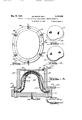
- Fig. 2 is a bottom view of the helmet shown in Fig. 1, the chin straps thereof being cut away for the sake of clarity.
- Fig. 3 is an exploded view showing separately the steel shell and the plastic inlay forming, when assembled, a complete helmet.
- Fig. 4 is a vertical sectional view of the assembled helmet, said view being taken in the direction of the arrows on the section plane passing through the line 4-4 of Fig. 1.
- Fig. 5 s an exploded view showing a set of pieces out out from plastic impregnated cloth from which pieces a plastic inlay is molded in accordance with the herein disclosed improved method.
- Fig. 6 is a perspective view showing a form block on which fiat pieces such as those shown in Fig. 5 are conveniently folded to an approximate shape of the inlay.
- Fig. 7 is a perspective view illustrating a starshaped cloth piece folded on said block approximately to the shape of the inlay, with its seams or places of juncture being connected together.
- Fig. 8 is an exploded perspective view illustrating cloth pieces of Fig. 5 folded together and ready to be assembled for molding.
- Fig. 9 is a vertical sectional view of a mold for forming and curing the plastic inlay.
- Fig. 10 is a top view of the mold shown in section in Fig. 9.
- Fig. 11 is a perspective view illustrating a molded inlay blank as the same comes out of the mold.
- Fig. 12 is a perspective view illustrating the inlay blank of Fig. 11 after the same has been properly trimmed.
- Fig. 13 is a sectional view showing a mold of a modified construction for forming and curing the plastic inlay.
- Fig. 14 illustrates a still further modification of the mold for curing such inlays, said mold being shown in vertical section.
- Fig. 15 shows a mold for molding an article with smooth inside surface, said mold being shown in vertical section.
- Figs. 16, 17 and 18 illustrate a modified step of molding the inlay, said step or operation being performed in two stages: first, by preforming the inlay, and second, by finally molding and BAQO, 522
- Fla. 16 is a sectional view showing a preforming mold with the assembled inlay pieces operatively arranged therein but before the rubber ball is expanded.
- Fig. 17 is a view similar in part to Fig, 16 but showing the rubber ball expanded and the pieces having assumed the shape of the inlay.
- Fig. 18 is a sectional view illustrating the mold for final forming and curing, the preformed inlay being shown therein pressed against the wall of the mold by the expanded rubber bag carried by the cover of the mold.
- an improved military helmet of twopiece construction including a liner or inlay made from plastic impregnated fabric or cloth.
- a liner or inlay made from plastic impregnated fabric or cloth.
- an improved method of making various articles from plastic treated cloths. fabrics or felted fibers and an improved apparatus for carrying out the molding or final forming and curing of such articles.
- Said improved method and apparatus are hereinafter disclosed as applied to making a lastic liner or inlay for a two-piece military helmet, shown in the drawings. It will be understood, however, that the present method and apparatus are not limited to making such inlays. but may be applied with equal success for making various other articles from the materials of the above general character, such for instance as parts of motor vehicle bodies, refrigeration cabinets. various sanitary articles and the like.
- plastic as used herein includes various thermosetting and thermoplastic materials which may be used in connection with fabric or fiber reinforcements and molded by application of heat and pressure.
- Figs. 1 to 4 wherein the improved military helmet is illustrated, the same comprises an outside shell 20 made preferably by stamping from sheet steel.
- an inlay or liner generally indicated by the numeral 2
- Within said inlay 2! there is secured in any suitable manner, such as with the aid of rivets 22, a supporting structure made of a plurality of interconnected straps and adapted to support said inlay on the wearer's head without permitting the inlay to contact the head of the wearer.
- the inlay is provided with an adjustable chin strap 23, while the shell 20 is similarly provided with a. heavier chin strap 24 having a buckle 25 and suitable adjustment means.
- the inlay supporting structure or suspension generally indicated by the numeral 26 does not of itself form a part of the present in vention and therefore no detailed description thereof is deemed necessary herein, this construction being clear from the drawings.
- the helmet herein disclosed is found in the fact that, as can be clearly seen in Fig. 4, the middle portions 21 and 28 of the shell 20 and the inlay 2
- the same effect may also be produced by having the lower portion of the walls of the shell and inlay extend parallel to each other on both sides of the helmet and therefore insuring frictional contact between the inlay and the shell at or along large frictional surfaces.
- an improved method of making the helmet inlay 2i from plastic treated cloth or fabric as well as various fiber materials in accordance with the improved method a suitable fabric or fiber material is first treated with plastic of any desirable or suitable character.
- plastic any desirable or suitable character.
- thermoplastic or thermosetting plastic materials such as thermoplastic resins, phenol formaldehyde. urea formaldehyde. synthetic resins, synthetic rubber, natural rubber, and the like may be used. Selection of the fabric material depends largely upon the character and use of the article to be made. For military helmet inlays it is preferable to use a closely woven cloth such as ordinary canvas.
- plastic material to the canvas After application of the plastic material to the canvas, the same is dried in any suitable manner depending on the nature and character oi. the plastic material and may then be used for cut-- ting therefrom pieces of desired outline.
- application of the plastic material to the canvas is made on special machines by spraying. large rolls of such plastic treated canvas may be prepared, dried, and stored for later use.
- Cutting out of pieces of desired outline from cloth may be done in any suitable manner such as with the aid of scissors or a knife, or with the aid of a suitable blanking die when a considerable number of layers of cloth may be arranged in a die and a corresponding number of pieces cut out in a single stroke of a press.
- the outline of the pieces cut out for making separate articles depends upon the shape thereof and the number of cloth layers used. In general, the outline of such pieces represents a developade or development surface of the article with some additional material along the seams or places of juncture thereof in order to produce overlapping seams.
- local reinforcement pieces may also be provided, outline of said pieces depending upon the character of the desired reinforcement.
- For the helmet inlay it is preferable to use two star-shaped pieces 33 and a top piece 3
- Pieces 33 each representing substantially a development surface of the inlay 2
- seams or places of juncture of the edges in pieces 33 are indicated by the numerals 33, and the pieces 33 after they are folded are designated by the numerals 34.
- Seams 33 after the connection therein is effected are additionally painted with the same plastic material in order to insure sulficient quantity thereof at said place of juncture.
- Fig. 8 illustrates two folded pieces 34 and the head reinforcing piece 3
- is put on the bottom of one of the pieces 34, and thereupon the second piece 34 is inserted into the first piece. It is desirable in the process of such assembly to stagger the seams 33 of pieces 34, thereby insuring a stronger construction.
- the mold device illustrated therein comprises a base 36 adapted to receive a hollow dome 31, which dome is separable from said base and may be secured thereto with the aid of any suitable locking devices, such as devices 38.
- the forming portion of the dome 31 is formed by an actual helmet shell arranged within said dome.
- the shell used in said dome is indicated by the numeral 23 used in Figs. 1-4 for designating the shell of the helmet shown therein.
- the shell 23 is fitted into the dome 31 in such a manner that it may be securely held therein.
- the shell may be supported in the dome in any suitable manner, such as by placing plugs between the shell 23 and the walls of the dome or by forming on the walls of said dome suitable lugs 39 which are shaped to contact the walls of the shell 23.
- the pressure exerting member of the molding device is exemplified by a rubber member or blanket 43 arranged on the base 33 and held in the assembled condition of the molding device between the base 36 and the edges of the dome 31 as can be clearly seen from an examination of Fig. 9.
- Fig. 9 illustrates the assembled molding device with the pieces 34 and 3
- the assembled pieces Because of heat the plastic material of the assembled pieces softens and as pressure within the chamber 41 increases, the assembled pieces yield to the pressure exerted thereon by the blanket 43, and being pressed by said blanket against the inner walls of the shell 23, they gradually assume the exact shape thereof. Due to the fact that seams 33 are somewhat loose, the edges of the pieces 34 separate in the process of such forming either because of the breaking of the weak threads used in sewing or by melting the spot connections produced by the soldering iron. Thus the cloth is permitted to rearrange itself in the process of molding without imposing any appreciable stresses and strains on the cloth material or fibers thereof.
- Another advantage of the present method of molding resides in the fact that pressure within the chamber 41 being equal in all directions, the blanket 43 presses on the assembled pieces uniformly in all directions, thereby permitting only necessary self-adjustment of cloth pieces without distorting their desirable arrangement. It will be understood that should such pieces be formed with the aid of a punch head moving into a forming portion of the die, unless a considerable draft or taper is provided on such walls, the punch may carry some pieces of cloth with it for an appreciable distance due to the friction between the stationary die walls and the movable punch walls with the cloth pieces between them. Such carrying of the pieces may completely disorganize their arrangement within an article and form wide gaps in the finished article, which gaps may, of course, be filled by the plastic and therefore make the defect of decreased strength thereof completely concealed from visual observation and detection.
- the live steam plug I2 is closed and the exhaust plug II is opened to exhaust the steam and reduce pressure within the chamber 41.
- the dome I1 is disconnected and removed from the base and the formed inlay blank is permitted to cool down.
- the inlay blank is then removed from the rubber blanket 4B and the rough edges thereof indicated by the numeral I! of Fig. 11 are trimmed off in any suitable 10 manner.
- the trimmed edges of the blank are additionally either treated with plastic material or covered with a suitable trimming strip.
- the blanket then assumes the form illustrated in Fig. 12.
- the supporting structure I is riveted to the inlay blank and the chin strap is secured thereto.
- heating and the pressure functions it is also possible to separate the heating and the pressure functions and to employ diflercnt fiuids for eflecting such functions.
- heating may be eflected with the aid of steam under definite pressure and temperature
- forming pressure may be attained pneumatically with the aid of compressed air.
- present invention is not limited to any particular type of the above mentioned fluids and that various other gaseous as well as liquid substances may also be used.
- Fig. 13 there is shown a molding device in which heating of the molded blank is eifected with the aid of steam, while pressure thereon is produced pneumatically, which is to say, with the aid of compressed air.
- the structure of Fig. 13 differs from the structure of Fig. 9 only in that feature of its construction that in the mold of Fig. 13 only a compressed air line is provided in the base of the mold, while steam line is provided in the dome part thereof in order to admit steam between the walls of said dome and the helmet shell 20.
- the structure illustrated therein comprises a base liil to which there is detachably connected with the aid of locking devices'ii a cover 62 of a box-like or other suitable shape.
- the shell 20 is arranged in said cover 52 in a way to form a steam chamber 63 between said shell 20 and the walls of the cover 52.
- a rubber blanket -or bag it arranged similarly to the rubber blanket 40 of the structure of Fig. 9 is provided, said blanket being adapted to be expanded by compressed air delivered into the air chamber 55 formed within said rubber blanket or bag 54, through a suitable conduit 56.
- Live steam is delivered into the steam chamber II through a conduit 61 controlled with the aid of a suitable plug it, while exhaust is efl'ected through a conduit 59 controlled with a suitable plug 60.
- conduit controlling plugs such as $8 and II are shown in the drawing diagrammatically and for the purpose of simplicity adjacent the molding device, while in an actual device they may be located in any convenient place on the line and, in fact, may be brought together on a single control board for more convenient control of the device.
- the steam is admitted into the chamber 68 from the line 84 by opening a plug 65 thereof and is exhausted through the line 68 by opening a plug 61 thereof.
- a cover 68 detachably secured to the base 62 with the aid of a number of locking devices 69 has an air line I0 provided therein.
- the steam under relatively low pressure may be constantly admitted into the chamber 63 for heating the shell 20.
- the assembled inlay pieces are first arranged within the shell 20 and thereupon a floating rubber member II is placed within said pieces. Next, the rubber bag I2 is arranged within said floating rubber member II, and the cover 68 is put in place and secured to the base 52.
- Air is then admitted into the air chamber 13 formed by the rubber bag I2 and the cover 68, in order to press the floating rubber member 1i and the assembled inlay pieces against the heated walls on the shell 20.
- Fig. 15 the form I5 of sheet metal is supported by lugs I6 on the base 11 to which is detachably secured with the aid of locks 18 a cover 19.
- a rubber membrane 00 is held in the assembled condition of the molding device between the base I1 and the cover I9 is adapted to be pressed by air pressure against the workpiece BI, pressing the same against the form 15. Pressure within the cover is created by admitting air therein through a line 82, while steam is admitted into the steam chamber formed under the form I5, through a steam line generally indicated by the numeral 83 and similar in its construction to the steam line system of the structure shown in Fig. 14.
- are first arranged in a shell 20 before the same is inserted into the base 85 as shown in Fig. 16, and the cover 90 together with the rubber ball 9i carried thereby is placed over the base, with the rubber ball entering the assembled inlay pieces. Air is then slowly admitted into the ball 90 expanding the same as shown in Fig. 17. Due to the action of the heat supplied by the steam coil, the plastic material with which the pieces 30 and ii are treated, softens suiliciently to permit the rubber ball to preform the inlay pieces and to impart to them the form of the inlay. After the inlay blank is so preformed, the cover 00 is removed and the shell 20 together with the inlay blank contained therein is transferred into the mold illustrated in Fi l. 18.
- the molding device shown in Fig. 18 comprises a base 05 provided with a shell receiving recess 96 and a steam chamber 91 into which steam is admitted through a live steam line 88 and exhausted through an exhaust line 90.
- a cover I00 has secured thereto in any suitable manner a rubber bag I02.
- the bag I02 is held against said cover by a ring I03 engaged by screws IN.
- the cover I00 is detachably secured to the base 85 with the aid of locks I04.
- An air line I05 is arranged in the cover, and the entire cover is suspended on a pulley I06 with the aid of a cord or cable I01 having on its free end a counterbalancing weight I08.
- the cover I00 is first removed and the shell 20 together with the preformed inlay blank contained therein is transferred from the molding device illustrated in Figs. 16 and 1'7 into the shell receiving recess 95 of the mold of Fig. 18.
- the cover I00 is then brought over the base 95 and the rubber bag I02 inserted into the inlay blank.
- the cover I00 is next secured to the base 95 with locks I08.
- the air is admitted through the line I05 into the air chamber I09 formed in the rubber bag I02, whereby said air bag is caused to expand and to press against the preformed inlay blank, pressing the same against the inner walls of shell 20.
- the preformed blank is then kept under heat and pressure as long as the plastic material and the canvas require.
- the shell 20 is removed from the base 85 by first removing the cover llil therefrom, and is transferred to another station for removal of the finally formed blank.
- the mold may be continuously used without delays necessary to remove the blank from the shell. With the apparatus illustrated in Figs. 16, 17 and 18 a somewhat faster production may be obtained.
- the pressure producing member is in the form of a fluid expanded rubber member. It will be understood, however, that under certain conditions it may be practical to use a solid rubber member and to apply mechanical pressure thereto, causing the rubber "to fiow” and to apply pressure to a blank. With the use of such members much greater pressures may be attained. If a member of this general character is employed, the shape of itshould be approximating the shape of the article to be molded somewhat closer than it is necessary when a fluid expanded bag is employed.
- an additional advantage of the above described method and apparatus is also due to the fact that presence of high spots, such as those found at overlapping seams, does not result in producing in molding excessively high localized pressures.
- the punch of the die first contacts such high spots and until they are crushed, no molding pressure can be exerted on the low spots of the mat or blank.
- the resilient pressure member "absorbs such high spots and exerts equal pressures both on the high and low spots of the blank, whereby crushing of fibers at such high spots is prevented.
- the floating member ll of the apparatus shown in Fig. 14 may be made of smooth material such as oil cloth, cellophane and the like, thus producing a somewhat smoother finish than is produced by rubber actually contacting the blank.
- a method of making a safety helmet from fiat plastic impregnated substantialhr unstretchable fabric material comprising the steps of providing from said material a plurality of pieces, each of said pieces substantially corresponding to the development of the helmet but being larger in area to ensure substantial overlapp of its meeting edges when folded to the shape of the helmet and molded, folding each of said pieces to an approximate shape of the helmet with edges of the fabric of the same piece overlapping each other for a substantial distance; assembling said pieces together to form a laminated preform; placing such preform into a heated mold and pressing it against the hot surface of said mold with the aid of a rubber member adapted to absorb the unevenness in the thickness of the walls of the preform produced by the overlapping edges in the preform and thus to exert substantially uniform pressure on all points thereof; and, leaving said preform in the mold under the resilient pressure of said rubber member for a predetermined time to cure the plastic.
- a method of making from plastic impregnated substantially unstretchable fabric material of hollow articles including relatively deep curved draws comprising the steps of providing from said material a plurality of pieces each having an area larger than the development of the corresponding area of the article in order to ensure substantial overlapping of the meeting edges of said development when folded to the shape of the article surface and molded; so folding each of said pieces and assembling them to form a laminated preform; placing said preform into a heated mold; and, pressing it against the walls of said mold with the aid of an expandable rubber member, and leaving said preform in the mold under the resilient pressure of said rubber member for a predetermined time to cure the plastic.
Description
May 13, 1947.
LE GRAND DALY METHOD OF MAKING ARTICLES FROI PLASTIC TREATED IA'I'ERIALS Filed larch 9, 194.2 6 Sheets-Sheet 1 1;; grand Z May 1947- LE GRAND DALY 2,420,522
METHOD OF MAKING ARTICLES FROM PLASTIC TREATED MATERIALS Filed March 9, 1942 6 Sheets-Sheet 2 INVENTOR jgy'rarrd Z4 Z y LE GRAND DALY 2,420,522
METHOD OF MAKING ARTICLES FROM PLASTIC TREATED MATERIALS Filed March 9, 1942 6 Sheets-Sheet 3 VENTOR e rand U411;
29 k '&
y 1947- LE GRAND DALY 2,420,522
METHOD OF MAKING ARTICLES FROM PLASTIC TREATED MATERIALS Filed March 9, 1942 6 Sheets-Sheet 4 L4 mvsmon 5 le Grand flatly,
a a-aw May 13, 1947. LE GRAND DALY 2,420,522
METHOD OF MAKING ARTICLES FROM PLASTIC TREATED MATERIALS Filed larch 9, 1942 6 Sheets-Sheet 5 I IIIII INVENTOR .1 r nd F415;
y 1947- LE GRAND DALY 2,420,522
METHOD OF MAKING ARTICLES FROM PLASTIC TREATED MATERIALS Filed March 9, 1942 6 Sheets-Sheet 6 .9/ g a i Fl E 15. Z0 INVENTOR 18$ ran! fldl ll.
Patented May 13, 1947 OFFICE METHOD OF MAKING ARTICLES FROM PLASTIC TREATED MATERIALS Le Grand Daly, Birmingham, Mich.
Application March 9, 1942, Serial No. 433,943
GCIa-ims.
This invention relates to molding methods and apparatus and more particularly to an improved method and apparatus for making various articles from plastic impregnated cloths or fabrics.
Heretofore considerable dimculties have been encountered in the art of making articles of the above general character and particularly in forming them to shapes including relatively deep draws or curved surfaces. Under one method of conventional practice of making such articles a flat sheet or a mat is first built-up of a desirable number of alternating layers of uncured plastic material and fabric: thereupon such flat sheet is operated upon in a die apparatus of a relatively powerful press and formed to desired shape between the correspondingly shaped punch and die of said apparatus. similarly to stamping metals. The die apparatus is usually heated in some suitable way in order to soften the plastic material and/or to effect curing thereof. Very high forming pressures such for instance as 5000 lbs. per square inch produced mechanically or hydraulically have been considered necessary to eflect proper forming and molding, in consequence whereof molding dies have been usually made similar to the dies used for stamping metals. 1. e. of heavy cast steel construction with hand shaped forming portions. Making such dies is a very tedious work requiring high skill and long time, and therefore in view of the high cost of molding dies and the necessity of using heavy powerful presses, setting-up for production even of a relatively small article of the foregoing character required relatively large investment and a long time. In addition to the above. still more serious difficulties have been confronted due to the fact that when the shape of the article produced included portions of considerable curvature or deep draws, damaging fibers of the reinforcing fabric in some sections of such curved portions and formation of folds or wrinkles in others were extremely diilicult to avoid. The latter diiliculty is due to the inability of cloth or of fabric fibers to stretch as much as it is necessary in order that a flat sheet of a fabric material would assume a curved shape. In other words, while stretching of metal fibers and "flow of metal within a metal sheet during stamping is considerable and may be carried on practically indefinitely by alternating forming and annealing of the stamped blank. such stretching and flow of material cannot be achieved in fabrics, and forming operations on flat pieces of fabric reinforced plastic materials invariably result in severely damaging the fabric fibers, formation of which fabric reinforced plastic articles or articles made of plastic treated fabrics may be molded without distorting the fabric or texture thereof, forming wrinkles and folds, weakening or breaking the fibers of the fabric; and which method also ensures that the fabric or cloth in the finished article retains its original strength.
A further object of the present invention is to provide an improved method for making various articles from plastic treated fabric materials, which articles do not have any sections internally weakened by the distortion of the fabric texture, which defects may not be apparent and may not be possible of visual detection.
A still further object of the present invention is to provide an improved method for maflng various articles from plastic impregnated fabric materials, which articles may be provided in desired places with additional local reinforcements of any desirable material.
A still further object of the invention is to provide an improved method for making various articles from the materials of the above described general character and having shapes making impossible to form them in molding dies of a single acting press due to the difllculties of withdrawing the die punch, and usually requiring multiple acting presses and very complicated dies.
A still further object of the present invention is to provide an improved method for making various articles from flat pieces of plastic covered or impregnated fabric or cloth, said method including an improved molding operation or step which can be easily eflected in very simple apparatus and does not require making of special molding dies or use of large presses.
A still further object of the present invention is to provide an improved method of making various articles from materials of the foregoing general character in large quantities with deliveries to be made in the shortest possible time, such as may be necessary in emergencies or in time for seasonal sales and in similar situations where because of the present improved method manufacture of such articles may be easily and quickly organized without the necessity of large investments in molding dies, presses or other expensive machinery as well as without securing ample supply of skilled help for making the molding dies, setting the machinery for production and securing other facilities which may be either scarce or even entirely unavailable at a particular time or place.
A still further object of the invention is to provide an improved method of making plastic or plastic treated inlays for various articles, such for instance as for two-piece military helmets, which method does not require making specially shaped molding dies but in accordance with which the inlay receiving portion of the article itself, such for instance as the steel shell of a two-piece helmet, may be used as a mold.
A still further object of the present invention is to provide an improved method of making plastic or plastic impregnated articles which method permits molding and curing of such articles using relatively low pressures which, in turn, permits use of a mold of thin sheet metal structures or members, such for instance as an actual part of the article or its first sheet metal model, as may be the case in making parts of motor vehicle bodies and the like.
A still further object of the present invention is to provide an improved method for making plastic or plastic impregnated inlays for a helmet of military or other type which method enables producing such inlays fast and in large quantities with low initial investment in machinery.
A still further object of the present invention is to provide an improved method for making plastic or plastic impregnated inlays for helmets, which method is simple, may be carried out with the aid of very inexpensive apparatus, enables high capacity production. decreases scrap and enables use of semi-skilled and unskilled labor.
Other objects of this invention will appear in the following description and appended claims, reference being had to the accompanying drawings forming a part of this specification wherein like reference characters designate corresponding parts in the several views.
Fig. l is a perspective view illustrating a twopiece military helmet including a liner or inlay made in accordance with the present invention.
In making articles such as safety helmets attempts have been made to cut out pieces of plastic impregnated fabric in the shape forming a geometric development into the shape of the helmet, fitting the meeting edges of the piece into sub stantially abutting relationship. Several pieces of such a nature are then assembled, with staggering of their abutting joints, and the pieces are molded in the molding dies into a helmet. It has been found, however, that fitting the edges of such pieces is a tedious work and that shifting of such pieces in the mold may cause separation of some of such abutting joints in some places, folds and high spots in others. In consequence thereof, the high spots so produced are crushed by the dies, squeezing out the plastic and producing so-called "dry spots," or places with insuflicient plastic bond and often damaged fibers, while in other places excessive resin accumulates in the so-called "resin pockets. The helmet or other article so produced is usually spotty in appearance, having light dry spots and dark resin pockets, and its strength and shockresisting capacity is decreased. Moreover, the abutting Joints with "fitted" edges have very little strength, and if such joints are running to the very edge of the article, such as to the very edge of the brim of a safetyhelmet, such helmets often fall along such seams under relatively light shock loads. In addition, such joints in the edge of the brim of a safety helmet form places where separation of the bonded cloth pieces may originate.
A large amount of inventive effort has heretofore been directed by those skilled in the art to the solution of the above problem. It was proposed, for instance, to use a knit preform individually made for each article such as a helmet. which preform is easily stretchable to desired shape. However, the cost of knitting such preforms is relatively high, and in many cases it is prohibitive for production in moderate quantitles or for experimental work, since it may require ordering such preforms from special mills and necessitate special set-up ofmachines for each special form. It was also proposed to use glass fiber fabrics of an open mesh weaveand with fibers so slippery as to permit forming "deep draws" by distorting the weave. While such expedients have solved some of the above discussed problems, they have introduced new difficulties preventing wider acceptance of such proposals.
Fig. 2 is a bottom view of the helmet shown in Fig. 1, the chin straps thereof being cut away for the sake of clarity.
Fig. 3 is an exploded view showing separately the steel shell and the plastic inlay forming, when assembled, a complete helmet.
Fig. 4 is a vertical sectional view of the assembled helmet, said view being taken in the direction of the arrows on the section plane passing through the line 4-4 of Fig. 1.
Fig. 5 .s an exploded view showing a set of pieces out out from plastic impregnated cloth from which pieces a plastic inlay is molded in accordance with the herein disclosed improved method.
Fig. 6 is a perspective view showing a form block on which fiat pieces such as those shown in Fig. 5 are conveniently folded to an approximate shape of the inlay.
Fig. 7 is a perspective view illustrating a starshaped cloth piece folded on said block approximately to the shape of the inlay, with its seams or places of juncture being connected together.
Fig. 8 is an exploded perspective view illustrating cloth pieces of Fig. 5 folded together and ready to be assembled for molding.
Fig. 9 is a vertical sectional view of a mold for forming and curing the plastic inlay.
Fig. 10 is a top view of the mold shown in section in Fig. 9.
Fig. 11 is a perspective view illustrating a molded inlay blank as the same comes out of the mold.
Fig. 12 is a perspective view illustrating the inlay blank of Fig. 11 after the same has been properly trimmed.
Fig. 13 is a sectional view showing a mold of a modified construction for forming and curing the plastic inlay.
Fig. 14 illustrates a still further modification of the mold for curing such inlays, said mold being shown in vertical section.
Fig. 15 shows a mold for molding an article with smooth inside surface, said mold being shown in vertical section.
Figs. 16, 17 and 18 illustrate a modified step of molding the inlay, said step or operation being performed in two stages: first, by preforming the inlay, and second, by finally molding and BAQO, 522
curing tne same. Particularly. Fla. 16 is a sectional view showing a preforming mold with the assembled inlay pieces operatively arranged therein but before the rubber ball is expanded.
Fig. 17 is a view similar in part to Fig, 16 but showing the rubber ball expanded and the pieces having assumed the shape of the inlay.
Fig. 18 is a sectional view illustrating the mold for final forming and curing, the preformed inlay being shown therein pressed against the wall of the mold by the expanded rubber bag carried by the cover of the mold.
Before explaining in detail the present invention it is to be understood that the invention is not limited in its application to the details of construction and arrangement of parts illustrated in the accompanying drawings. since the invention is capable of other embodiments and of being practiced or carried out in various ways. Also it is to be understood that the phraseology or terminology employed herein is for the purpose of description and not of limitation.
In the drawings there is shown. by way of example, an improved military helmet of twopiece construction. including a liner or inlay made from plastic impregnated fabric or cloth. There is hereinafter described in detail and illustrated in the drawings an improved method of making various articles from plastic treated cloths. fabrics or felted fibers, and an improved apparatus for carrying out the molding or final forming and curing of such articles. Said improved method and apparatus are hereinafter disclosed as applied to making a lastic liner or inlay for a two-piece military helmet, shown in the drawings. It will be understood, however, that the present method and apparatus are not limited to making such inlays. but may be applied with equal success for making various other articles from the materials of the above general character, such for instance as parts of motor vehicle bodies, refrigeration cabinets. various sanitary articles and the like. It should also be understood that the term plastic" as used herein includes various thermosetting and thermoplastic materials which may be used in connection with fabric or fiber reinforcements and molded by application of heat and pressure.
Referring now to Figs. 1 to 4 wherein the improved military helmet is illustrated, the same comprises an outside shell 20 made preferably by stamping from sheet steel. Within said helmet shell 20 there is fitted an inlay or liner generally indicated by the numeral 2|. Within said inlay 2! there is secured in any suitable manner, such as with the aid of rivets 22, a supporting structure made of a plurality of interconnected straps and adapted to support said inlay on the wearer's head without permitting the inlay to contact the head of the wearer. The inlay is provided with an adjustable chin strap 23, while the shell 20 is similarly provided with a. heavier chin strap 24 having a buckle 25 and suitable adjustment means. The inlay supporting structure or suspension generally indicated by the numeral 26 does not of itself form a part of the present in vention and therefore no detailed description thereof is deemed necessary herein, this construction being clear from the drawings.
An important advantage of the helmet herein disclosed is found in the fact that, as can be clearly seen in Fig. 4, the middle portions 21 and 28 of the shell 20 and the inlay 2| respectively are made somewhat larger than the portions adjacent the edges thereof, and therefore some effort is necessary for forcing the inlay into the shell and for withdrawing said inlay therefrom. By virtue of such a construction easy separation of the shell and inlay under conditions of actual use is prevented. In accordance with the invention the same effect may also be produced by having the lower portion of the walls of the shell and inlay extend parallel to each other on both sides of the helmet and therefore insuring frictional contact between the inlay and the shell at or along large frictional surfaces. This will also prevent any undesirable movement or rocking of the steel shell on the inlay and thus will make the two-piece helmet in its fully assembled condition in effect a one-piece construction and yet will permit attainment of the advantages resulting from its laminated construction. such as the advantage of bullet deflection.
In accordance with the invention there is provided an improved method of making the helmet inlay 2i from plastic treated cloth or fabric as well as various fiber materials. In accordance with the improved method a suitable fabric or fiber material is first treated with plastic of any desirable or suitable character. Various commercially available thermoplastic or thermosetting plastic materials. such as thermoplastic resins, phenol formaldehyde. urea formaldehyde. synthetic resins, synthetic rubber, natural rubber, and the like may be used. Selection of the fabric material depends largely upon the character and use of the article to be made. For military helmet inlays it is preferable to use a closely woven cloth such as ordinary canvas.
In treating the canvas with plastic material which may be done either in any suitable machine or by hand, I prefer to cover with plastic material both surfaces of the canvas completely either by painting or spraying such surfaces. It is preferable to cover only the surfaces of the cloth without actually permitting the plastic material to penetrate through the entire thickness of the cloth and to surround the separate threads or fibers thereof. By virtue of such a treatment it is possible to apply a considerable amount of plastic material to the canvas or cloth and yet to preserve in the cloth a desired degree of softness necessary for proper folding of the cloth pieces in later stages of the inlay making. Such softness is retained by the canvas due to the fact that although the outside surfaces thereof after the plastic material solidifies become somewhat stlff or rigid, the inside of the cloth is still dry and separate fibers may move slightly with respect to each other and to adjust themselves in bending the cloth. It can be understood that s ould plastic material be driven between the separate fibers and threads into the entire thickness of the cloth as may be done by such plastic applying processes as rolling, after the plastic material solidifies, the separate fibers of the cloth are prevented from moving with respect to each other, and if bending or creasing of the cloth takes place along a particular line, extremely high stresses are imposed on separate fibers along that line, which may easily produce breaking of such overstrained fibers at said line. In actual molding such broken fibers and spaces between them are, of course, filled with plastic and cannot be noticed by an outside examination of the finished article, but nevertheless the strength of the cloth is thereby considerably reduced.
After application of the plastic material to the canvas, the same is dried in any suitable manner depending on the nature and character oi. the plastic material and may then be used for cut-- ting therefrom pieces of desired outline. When application of the plastic material to the canvas is made on special machines by spraying. large rolls of such plastic treated canvas may be prepared, dried, and stored for later use.
Cutting out of pieces of desired outline from cloth may be done in any suitable manner such as with the aid of scissors or a knife, or with the aid of a suitable blanking die when a considerable number of layers of cloth may be arranged in a die and a corresponding number of pieces cut out in a single stroke of a press. The outline of the pieces cut out for making separate articles depends upon the shape thereof and the number of cloth layers used. In general, the outline of such pieces represents a developade or development surface of the article with some additional material along the seams or places of juncture thereof in order to produce overlapping seams. In addition, local reinforcement pieces may also be provided, outline of said pieces depending upon the character of the desired reinforcement. For the helmet inlay it is preferable to use two star-shaped pieces 33 and a top piece 3|, as shown in Fig. 5.
Pieces 33 each representing substantially a development surface of the inlay 2|, are folded on a form block 32 illustrated in Fig. 8 to an approximate form of the inlay, as shown in Fig. 7, and the seams are loosely connected in any suitable manner, such for instance as by touching them in places with a heated body such as a soldering iron or by sewing them together with weak thread easily broken. In the drawings such seams or places of juncture of the edges in pieces 33 are indicated by the numerals 33, and the pieces 33 after they are folded are designated by the numerals 34. Seams 33 after the connection therein is effected are additionally painted with the same plastic material in order to insure sulficient quantity thereof at said place of juncture.
Fig. 8 illustrates two folded pieces 34 and the head reinforcing piece 3| ready to be assembled. In assembly, the head piece 3| is put on the bottom of one of the pieces 34, and thereupon the second piece 34 is inserted into the first piece. It is desirable in the process of such assembly to stagger the seams 33 of pieces 34, thereby insuring a stronger construction.
After the pieces 34 and 3| are thus assembled, they are ready to be finally formed and cured in accordance with the present improved method. Such final forming and curing may be done either in a single step or operation or may be divided into a number'of steps, such for instance as into a preforming operation and into the final forming and curing operation. If said final forming and curing is effected in a single operation, the same may be done in a, mold illustrated in Fig. 9. Referring to said figure, the mold device illustrated therein comprises a base 36 adapted to receive a hollow dome 31, which dome is separable from said base and may be secured thereto with the aid of any suitable locking devices, such as devices 38. The forming portion of the dome 31 is formed by an actual helmet shell arranged within said dome. In order to indicate that such shell is a part of the actual helmet, the shell used in said dome is indicated by the numeral 23 used in Figs. 1-4 for designating the shell of the helmet shown therein. The shell 23 is fitted into the dome 31 in such a manner that it may be securely held therein. The shell may be supported in the dome in any suitable manner, such as by placing plugs between the shell 23 and the walls of the dome or by forming on the walls of said dome suitable lugs 39 which are shaped to contact the walls of the shell 23. The pressure exerting member of the molding device is exemplified by a rubber member or blanket 43 arranged on the base 33 and held in the assembled condition of the molding device between the base 36 and the edges of the dome 31 as can be clearly seen from an examination of Fig. 9. A live steam line 4| controlled by a suitable plug 42 and opening with a port 43 into a steam chamber 41 formed under the blanket 43, is provided for admitting live steam into the mold. Similarly for releasing the exhaust steam from the mold there is provided an exhaust steam line 44 controlled with the aid of a plug 45 and opening into the steam chamber with a port 46.
When the pieces 34 and 3| are assembled together as described and are ready to be molded, the dome 31 is removed from the base 33 and the assembled pieces are arranged over the upwardly extending middle portion of the blanket 43. Thereupon the dome 31 is placed over the blanket 43 and the assembled pieces, and is secured to the base 33 with the aid of the locking devices 33. Fig. 9 illustrates the assembled molding device with the pieces 34 and 3| arranged therein for final forming and curing. When the mold is so assembled with the pieces arranged therein, the live steam is then slowly admitted by opening the live steam plug 42 and letting the steam enter the chamber 41. The steam entering said chamber 41 heats the blanket 43 and slowly presses it against the assembled pieces 34 and 3| transferring to them by conduction the heat from the blanket 43. Because of heat the plastic material of the assembled pieces softens and as pressure within the chamber 41 increases, the assembled pieces yield to the pressure exerted thereon by the blanket 43, and being pressed by said blanket against the inner walls of the shell 23, they gradually assume the exact shape thereof. Due to the fact that seams 33 are somewhat loose, the edges of the pieces 34 separate in the process of such forming either because of the breaking of the weak threads used in sewing or by melting the spot connections produced by the soldering iron. Thus the cloth is permitted to rearrange itself in the process of molding without imposing any appreciable stresses and strains on the cloth material or fibers thereof. The plastic material being under such condition in its liquid form, internal adjustment of the fibers within separate pieces of cloth also takes place, and therefore the individual fibers under such conditions do not carry any appreciable loads as is the case when they are stretched in a single cloth piece which is being formed with the aid of a die punch of conventional method. By virtue of method the cloth retains its original strength and when the article is molded and the plastic solidifies, the fibers thereof are in a substantially unstrained condition which is not the case with articles produced in accordance with the above described conventional methods.
Another advantage of the present method of molding resides in the fact that pressure within the chamber 41 being equal in all directions, the blanket 43 presses on the assembled pieces uniformly in all directions, thereby permitting only necessary self-adjustment of cloth pieces without distorting their desirable arrangement. It will be understood that should such pieces be formed with the aid of a punch head moving into a forming portion of the die, unless a considerable draft or taper is provided on such walls, the punch may carry some pieces of cloth with it for an appreciable distance due to the friction between the stationary die walls and the movable punch walls with the cloth pieces between them. Such carrying of the pieces may completely disorganize their arrangement within an article and form wide gaps in the finished article, which gaps may, of course, be filled by the plastic and therefore make the defect of decreased strength thereof completely concealed from visual observation and detection.
It can also be understood from an examination of Fig. 9 that by virtue of using a fluid expanded resilient blanket, forms may be produced which could not be stamped with the aid of a conventional molding die because of the fact that a single acting punch cannot be withdrawn therefrom. An additional advantage of the present method resides in the fact that relatively low steam pressures may be utilized and give good results. As has been explained above, in conventional methods pressures such as 5000 pounds per square inch have been considered necessary for efiecting proper molding of articles of this general character. With the present improved method selection of the proper pressure depends upon the character of the fabric material used. In small light articles where soft silk is used as the reinforcing material, such pressure may be very low, and in fact, 25 pounds per square inch may give satisfactory results. If on the other hand very heavy closely woven cloth is used in many layers and, in addition, the shape to be Produced includes curvature of rather small radii, a higher pressure should be employed. For very smooth finishes higher pressures are also desirable. However, under ordinary conditions it is not necessary to use pressures above 1500 pounds per square inch. In fact, pressure of 1000 pounds per square inch is considered suflicient for rather severe conditions. Thus, with the present improved method the pressure such as indicated above is still five times as small as the average pressures used in conventional methods. In actual practice, however, a much lower pressure than 1000 pounds per square inch is desirable. With the cloth used for the helmet inlays pressures of 100 pounds per square inch gives very satisfactory results and such pressure is preferred With the use of the above described method using pressure of approximately 100 pounds per square inch, which pressure implies a corresponding definite temperature of the steam (wet or saturated), the time necessary to effect complete final forming and curing of average materials is approximately five to twenty minutes. With higherpressures and temperatures somewhat different duration of the forming and ouring period may be desirable, and the same should be determined experimentally for the particular conditions and materials used.
After the forming and curing process is completed, the live steam plug I2 is closed and the exhaust plug II is opened to exhaust the steam and reduce pressure within the chamber 41. Thereupon the dome I1 is disconnected and removed from the base and the formed inlay blank is permitted to cool down. The inlay blank is then removed from the rubber blanket 4B and the rough edges thereof indicated by the numeral I! of Fig. 11 are trimmed off in any suitable 10 manner. The trimmed edges of the blank are additionally either treated with plastic material or covered with a suitable trimming strip. The blanket then assumes the form illustrated in Fig. 12. Thereupon the supporting structure I is riveted to the inlay blank and the chin strap is secured thereto. These operations complete the inlay and the same is now ready for use, gather separately or in connection with the shell It will now be clear in view of the foregoing that in the apparatus described in Fig. 0 steam acts as both the pressure and the heating medium and heat is conducted to the inlay pieces through the blanket 40. Such method and apparatus is very simple and may be successfully used under many conditions.
In accordance with the invention it is also possible to separate the heating and the pressure functions and to employ diflercnt fiuids for eflecting such functions. For instance, while heating may be eflected with the aid of steam under definite pressure and temperature, forming pressure may be attained pneumatically with the aid of compressed air. It will be understood however that the present invention is not limited to any particular type of the above mentioned fluids and that various other gaseous as well as liquid substances may also be used.
In Fig. 13 there is shown a molding device in which heating of the molded blank is eifected with the aid of steam, while pressure thereon is produced pneumatically, which is to say, with the aid of compressed air. Generally, the structure of Fig. 13 differs from the structure of Fig. 9 only in that feature of its construction that in the mold of Fig. 13 only a compressed air line is provided in the base of the mold, while steam line is provided in the dome part thereof in order to admit steam between the walls of said dome and the helmet shell 20. Referring now to Fig. 13, the structure illustrated therein comprises a base liil to which there is detachably connected with the aid of locking devices'ii a cover 62 of a box-like or other suitable shape. The shell 20 is arranged in said cover 52 in a way to form a steam chamber 63 between said shell 20 and the walls of the cover 52. A rubber blanket -or bag it arranged similarly to the rubber blanket 40 of the structure of Fig. 9 is provided, said blanket being adapted to be expanded by compressed air delivered into the air chamber 55 formed within said rubber blanket or bag 54, through a suitable conduit 56. Live steam is delivered into the steam chamber II through a conduit 61 controlled with the aid of a suitable plug it, while exhaust is efl'ected through a conduit 59 controlled with a suitable plug 60. It should be understood that locations of the conduit controlling plugs such as $8 and II are shown in the drawing diagrammatically and for the purpose of simplicity adjacent the molding device, while in an actual device they may be located in any convenient place on the line and, in fact, may be brought together on a single control board for more convenient control of the device.
In operation, after the assembled inlay pieces 34 and II are arranged on the rubber bag it and the cover 52 afllxed to the base 50, steam is first admitted into the chamber 63 to heat the shell 20, whereupon air is gradually admitted through the conduit 58 and the rubber blanket or membrane is caused to press the inlay pieces against the shell 20. After the forming and curing process is completed, the air and the steam lines are closed, and the exhaust conduit opened. 'I'hereupon the mold is opened and the molded inlay blank removed therefrom as described above. With the above described construction any desired pressure may be attained without ail'ecting the temperature of the steam. It should be understood that temperature of saturated and wet steam depends only upon the pressure thereof. In the structure of Fig. 13 very low pressure steam may be used for heating while higher pressures may be employed for expanding the bag 54 without increasing the curing temperature. By superheating the steam, higher temperatures may be attained without increasing the pressure of the steam which may be undesirable in molds of light construction.
Fig. 14 illustrates a molding device of a still further modified construction. The structure of Fig. 14 is constructed substantially on the same A principle as Fig. 13, the diflerence lying mainly in the fact that in the structure of Fig. 14 the shell is arranged in the base of the device and therefore the inlay blank or the assembled pieces for forming the same are arranged within the shell 20 as they are put in the mold rather than assembled on the rubber bag as is done in the structures of Figs. 9 and 13. Referring now more particularly to Fig. 14, the structure illustrated therein comprises a base 62 of a box-like or any other suitable shape, having a steam chamber 63 formed between its walls and the shell 20. The steam is admitted into the chamber 68 from the line 84 by opening a plug 65 thereof and is exhausted through the line 68 by opening a plug 61 thereof. A cover 68 detachably secured to the base 62 with the aid of a number of locking devices 69 has an air line I0 provided therein. In operation, the steam under relatively low pressure may be constantly admitted into the chamber 63 for heating the shell 20. The assembled inlay pieces are first arranged within the shell 20 and thereupon a floating rubber member II is placed within said pieces. Next, the rubber bag I2 is arranged within said floating rubber member II, and the cover 68 is put in place and secured to the base 52. Air is then admitted into the air chamber 13 formed by the rubber bag I2 and the cover 68, in order to press the floating rubber member 1i and the assembled inlay pieces against the heated walls on the shell 20. By the provision of the floating member II a somewhat better and easier self-arrangement of the cloth pieces in forming is permitted, which is important if particularly smooth finishes are desirable.
It will be understood that with the structures illustrated in Figs. 9, 13 and 14, the outside surface of the molded inlay will come out smooth, while the inside thereof will exhibit the roughness of the cloth. If smooth surface is desired on the inside rather than the outside of an article, it is molded against the outside of the form. A molding apparatus for an article of a plate shape and producing smooth surface on the inside thereof is illustrated in Fig. 15, said apparatus being constructed similar to the molding apparatus of Fig. 14.
In the structure of Fig. 15 the form I5 of sheet metal is supported by lugs I6 on the base 11 to which is detachably secured with the aid of locks 18 a cover 19. A rubber membrane 00 is held in the assembled condition of the molding device between the base I1 and the cover I9 is adapted to be pressed by air pressure against the workpiece BI, pressing the same against the form 15. Pressure within the cover is created by admitting air therein through a line 82, while steam is admitted into the steam chamber formed under the form I5, through a steam line generally indicated by the numeral 83 and similar in its construction to the steam line system of the structure shown in Fig. 14.
Figs. 16, 1'7 and 18 illustrate a modified type of the apparatus in which the step or operation of the final forming and curing is effected in two stages: first, by preforming the article in the device of Figs. 16 and 17 and thereupon finally forming and curing the same in the device illustrated in Fig. 18.
The prei'orming device illustrated in Figs. 16 and I1 comprises a base 85 adapted to receive a shell 20, which shell may be easily inserted in place and removed therefrom by getting hold of the edges thereof at recesses provided at the upper edges of the base, such as at recesses 80. Within the base 05 there is arranged a steam coil 81 controlled by plugs 88 and 09, said steam coil arranged so that it comes in close proximity to the shell 20 when the same is inserted into the base 85. An electric coil may also be used. A cover 00 carrying a rubber ball 9| is adapted to be placed over the base 85. The rubber ball 8| may be expanded by admitting air under pressure therein through a conduit 82 controlled by a plug 93. In operation, the assembled inlay pieces ill and 3| are first arranged in a shell 20 before the same is inserted into the base 85 as shown in Fig. 16, and the cover 90 together with the rubber ball 9i carried thereby is placed over the base, with the rubber ball entering the assembled inlay pieces. Air is then slowly admitted into the ball 90 expanding the same as shown in Fig. 17. Due to the action of the heat supplied by the steam coil, the plastic material with which the pieces 30 and ii are treated, softens suiliciently to permit the rubber ball to preform the inlay pieces and to impart to them the form of the inlay. After the inlay blank is so preformed, the cover 00 is removed and the shell 20 together with the inlay blank contained therein is transferred into the mold illustrated in Fi l. 18.
The molding device shown in Fig. 18 comprises a base 05 provided with a shell receiving recess 96 and a steam chamber 91 into which steam is admitted through a live steam line 88 and exhausted through an exhaust line 90. A cover I00 has secured thereto in any suitable manner a rubber bag I02. In the present embodiment of the invention the bag I02 is held against said cover by a ring I03 engaged by screws IN. The cover I00 is detachably secured to the base 85 with the aid of locks I04. An air line I05 is arranged in the cover, and the entire cover is suspended on a pulley I06 with the aid of a cord or cable I01 having on its free end a counterbalancing weight I08. In operation, the cover I00 is first removed and the shell 20 together with the preformed inlay blank contained therein is transferred from the molding device illustrated in Figs. 16 and 1'7 into the shell receiving recess 95 of the mold of Fig. 18. The cover I00 is then brought over the base 95 and the rubber bag I02 inserted into the inlay blank. The cover I00 is next secured to the base 95 with locks I08. Thereupon the air is admitted through the line I05 into the air chamber I09 formed in the rubber bag I02, whereby said air bag is caused to expand and to press against the preformed inlay blank, pressing the same against the inner walls of shell 20. The preformed blank is then kept under heat and pressure as long as the plastic material and the canvas require. After the forming and curing process is completed, the shell 20 is removed from the base 85 by first removing the cover llil therefrom, and is transferred to another station for removal of the finally formed blank. Thus the mold may be continuously used without delays necessary to remove the blank from the shell. With the apparatus illustrated in Figs. 16, 17 and 18 a somewhat faster production may be obtained.
In the molding devices herein illustrated and described, the pressure producing member is in the form of a fluid expanded rubber member. It will be understood, however, that under certain conditions it may be practical to use a solid rubber member and to apply mechanical pressure thereto, causing the rubber "to fiow" and to apply pressure to a blank. With the use of such members much greater pressures may be attained. If a member of this general character is employed, the shape of itshould be approximating the shape of the article to be molded somewhat closer than it is necessary when a fluid expanded bag is employed.
It will now be understood in view of the foregoing that an additional advantage of the above described method and apparatus is also due to the fact that presence of high spots, such as those found at overlapping seams, does not result in producing in molding excessively high localized pressures. In the conventional die molds, the punch of the die first contacts such high spots and until they are crushed, no molding pressure can be exerted on the low spots of the mat or blank. In the process and apparatus of the present invention the resilient pressure member "absorbs such high spots and exerts equal pressures both on the high and low spots of the blank, whereby crushing of fibers at such high spots is prevented.
A number of modifications may be effected in the above described method and apparatus without departing from the scope of the present invention. For instance, steam may be used in molds similar to those illustrated in Figs. l3, l4, l and 18 both for heating the shell 20 and expanding the rubber member. It should also be understood that the term "rubber as is used in both the specification and the following claims includes natural as well as synthetic rubber, and also any rubber-like or resilient material suitable for the purposes described.
Under certain conditions it is desirable to cut the pieces from the fibrous material before it is treated with plastic, and to apply such plastic onto the pieces either by painting or spraying the plastic in liquid or powder form after the pieces are so cut out, or even after they are folded to the approximate shape of the article or assembled in the mold.
In cases where smoother finish is desirable, the floating member ll of the apparatus shown in Fig. 14 may be made of smooth material such as oil cloth, cellophane and the like, thus producing a somewhat smoother finish than is produced by rubber actually contacting the blank.
There is thus provided an improved method and apparatus whereby various articles made of fabric reinforced plastic materials or plastic treated fabrics and fiber materials may be molded with the use of relatively low pressures and with the aid of inexpensive apparatus, whereby obiects of the present invention listed above and numerous additional advantages are attained.
I claim:
1. A method of making a safety helmet from fiat plastic impregnated substantialhr unstretchable fabric material, said method comprising the steps of providing from said material a plurality of pieces, each of said pieces substantially corresponding to the development of the helmet but being larger in area to ensure substantial overlapp of its meeting edges when folded to the shape of the helmet and molded, folding each of said pieces to an approximate shape of the helmet with edges of the fabric of the same piece overlapping each other for a substantial distance; assembling said pieces together to form a laminated preform; placing such preform into a heated mold and pressing it against the hot surface of said mold with the aid of a rubber member adapted to absorb the unevenness in the thickness of the walls of the preform produced by the overlapping edges in the preform and thus to exert substantially uniform pressure on all points thereof; and, leaving said preform in the mold under the resilient pressure of said rubber member for a predetermined time to cure the plastic.
2. In a method of making from plastic impr nai'ed fabric a hollow laminated article, its hollow being at least in one place larger than the largest aperture in the article wall, the steps of providing from said material a plurality of pieces, each piece being a development of at least a portion of the article surface but having additional material along its meeting edges in order to ensure their substantial overlapp g when the piece is folded to the shape of the article surface and molded; folding said pieces and assembling them together to form a laminated preform; placing said preform into a curing mold; introducing into said preform an expandable rubber member and expanding the same to press the preform against the walls of the mold, contracting the rubber member and withdrawing it from the hollow article after the plastic is cured.
3. A method of making from plastic impregnated substantially unstretchable fabric material of hollow articles including relatively deep curved draws, said method comprising the steps of providing from said material a plurality of pieces each having an area larger than the development of the corresponding area of the article in order to ensure substantial overlapping of the meeting edges of said development when folded to the shape of the article surface and molded; so folding each of said pieces and assembling them to form a laminated preform; placing said preform into a heated mold; and, pressing it against the walls of said mold with the aid of an expandable rubber member, and leaving said preform in the mold under the resilient pressure of said rubber member for a predetermined time to cure the plastic.
4. In a method of making from fiat plastic impregnated cloth of a hollow article including curved walls, the steps of cutting from said cloth a piece foaming substantially a development of said article with additional cloth being provided on said development at least at some of the edges thereof intended to meet when said development is folded to the shape of the article, the amount of such additional cloth being sufiicicnt to ensure substantial overlapping of said edges both when the development is folded as well as after the same is molded, folding said development to the approximate shape of the article to make a preform, and molding said preform in a mold 15 under the pressure of a rubber member adapted to absorb the high spots formed at the overlapping edges of the preform and thus to exert substantially uniform pressure on all points thereof.
5. In a method of making from flat plastic treated cloth of a hollow article including curved surfaces, the steps of cutting from said cloth at least one piece forming substantially a development of the surface of said article with additional cloth being allowed on said piece at the edges thereof adapted to meet when said development is folded, the amount of such additional cloth being suiilcient to ensure overlapping of such meeting edges for a substantial distance both when the development is folded as well as after the same is molded; folding said development to the approximate form of the surface of said article with its meeting edges overlapping each other to make a preform, and molding said preform in a heated sheet metal mold under the pressure of a rubber member adapted to absorb the high spots formed at the overlaps of said meeting edges and, thus, to exert substantially uniform pressure on all points of said preform.
6. In a method of making from flat plastic impregnated cloth of a hollow article including curved surfaces, the steps of cutting from said cloth a piece forming substantially a development of at least a portion of the surface of said article with additional cloth being allowed on said piece at the edges thereof adapted to meet when said development is folded, the amount of 16 such additional cloth being sufficient to ensure overlapping of such meeting edges for a substantial distance both when the development is folded as well as after the same is molded, folding said development to the approximate form of the surface of said article to make a preform with its meetin edges overlapping each other, and molding said preform in a steam heated mold under the pressure of a water-expandable rubber member adapted to absorb the high spots formed at the overlaps of said meeting edges and, thus. to exert on said overlaps substantially the same pressure as on other points of said preform.
LE GRAND DALY.
REFERENCES CITED The following references are of record in the file of this patent:
UNITED STATES PATENTS Number Name Date 1,213,051 Wickes Jan. 16, 1917 2,123,275 Dym July 12, 1938 535,773 Rowley Mar. 12, 1895 1,343,185 Kendal] June 8, 1920 1,589,464 Frederick June 22, 1926 2,328,992 Nielsen Sept. 7, 1943 1,912,931 Clay June 6, 1933 2,308,453 Potchen Jan. 12, 1943 1,475,623 Edgerton Nov. 27, 1923 1,839,436 Wood June 5, 1932 1,640,543 G'udge Aug. 30, 1927 Certificate of Correction latent No. 2,420,522.
May 13, 1947.
LE GRAND DALY It is hereby certified that error appears in the numbered patent requiring correction as follows:
rinted specification of the above olumn 3, line 49, beginning with the words In making strike out all to and including the syllable and period posals.
in line 26, column 4, and insert the same in column 2,
me 3, before the sentence beginning with One of"; and that the said Letters Patent should be read with this correction therein.
Signed and sealed this 22nd day of July, A. D. 1947.
LESLIE FRAZER,
First Assistant Uommisaioner of Patents.
15 under the pressure of a rubber member adapted to absorb the high spots formed at the overlapping edges of the preform and thus to exert substantially uniform pressure on all points thereof.
5. In a method of making from flat plastic treated cloth of a hollow article including curved surfaces, the steps of cutting from said cloth at least one piece forming substantially a development of the surface of said article with additional cloth being allowed on said piece at the edges thereof adapted to meet when said development is folded, the amount of such additional cloth being suiilcient to ensure overlapping of such meeting edges for a substantial distance both when the development is folded as well as after the same is molded; folding said development to the approximate form of the surface of said article with its meeting edges overlapping each other to make a preform, and molding said preform in a heated sheet metal mold under the pressure of a rubber member adapted to absorb the high spots formed at the overlaps of said meeting edges and, thus, to exert substantially uniform pressure on all points of said preform.
6. In a method of making from flat plastic impregnated cloth of a hollow article including curved surfaces, the steps of cutting from said cloth a piece forming substantially a development of at least a portion of the surface of said article with additional cloth being allowed on said piece at the edges thereof adapted to meet when said development is folded, the amount of 16 such additional cloth being sufficient to ensure overlapping of such meeting edges for a substantial distance both when the development is folded as well as after the same is molded, folding said development to the approximate form of the surface of said article to make a preform with its meetin edges overlapping each other, and molding said preform in a steam heated mold under the pressure of a water-expandable rubber member adapted to absorb the high spots formed at the overlaps of said meeting edges and, thus. to exert on said overlaps substantially the same pressure as on other points of said preform.
LE GRAND DALY.
REFERENCES CITED The following references are of record in the file of this patent:
UNITED STATES PATENTS Number Name Date 1,213,051 Wickes Jan. 16, 1917 2,123,275 Dym July 12, 1938 535,773 Rowley Mar. 12, 1895 1,343,185 Kendal] June 8, 1920 1,589,464 Frederick June 22, 1926 2,328,992 Nielsen Sept. 7, 1943 1,912,931 Clay June 6, 1933 2,308,453 Potchen Jan. 12, 1943 1,475,623 Edgerton Nov. 27, 1923 1,839,436 Wood June 5, 1932 1,640,543 G'udge Aug. 30, 1927 Certificate of Correction latent No. 2,420,522.
May 13, 1947.
LE GRAND DALY It is hereby certified that error appears in the numbered patent requiring correction as follows:
rinted specification of the above olumn 3, line 49, beginning with the words In making strike out all to and including the syllable and period posals.
in line 26, column 4, and insert the same in column 2,
me 3, before the sentence beginning with One of"; and that the said Letters Patent should be read with this correction therein.
Signed and sealed this 22nd day of July, A. D. 1947.
LESLIE FRAZER,
First Assistant Uommisaioner of Patents.
Priority Applications (2)
| Application Number | Priority Date | Filing Date | Title |
|---|---|---|---|
| US433943A US2420522A (en) | 1942-03-09 | 1942-03-09 | Method of making articles from plastic treated materials |
| US738960A US2532442A (en) | 1942-03-09 | 1947-04-02 | Molded article |
Applications Claiming Priority (1)
| Application Number | Priority Date | Filing Date | Title |
|---|---|---|---|
| US433943A US2420522A (en) | 1942-03-09 | 1942-03-09 | Method of making articles from plastic treated materials |
Publications (1)
| Publication Number | Publication Date |
|---|---|
| US2420522A true US2420522A (en) | 1947-05-13 |
Family
ID=23722185
Family Applications (1)
| Application Number | Title | Priority Date | Filing Date |
|---|---|---|---|
| US433943A Expired - Lifetime US2420522A (en) | 1942-03-09 | 1942-03-09 | Method of making articles from plastic treated materials |
Country Status (1)
| Country | Link |
|---|---|
| US (1) | US2420522A (en) |
Cited By (35)
| Publication number | Priority date | Publication date | Assignee | Title |
|---|---|---|---|---|
| US2448114A (en) * | 1943-05-18 | 1948-08-31 | Goodrich Co B F | Method for making heat-molded articles containing fabric reinforcements |
| US2556060A (en) * | 1946-03-06 | 1951-06-05 | Globe Wernicke Co | Method of making plastic desk tops |
| US2625683A (en) * | 1947-12-08 | 1953-01-20 | Prot Inc | Crash helmet |
| US2739640A (en) * | 1947-10-10 | 1956-03-27 | Globe Wernicke Co | Method of producing a linoleum covered desk top |
| US2747180A (en) * | 1952-06-20 | 1956-05-22 | Zenith Plastics Company | Radar reflector |
| US2746049A (en) * | 1951-11-23 | 1956-05-22 | Willson Products Inc | Helmet |
| US2922417A (en) * | 1953-06-11 | 1960-01-26 | Johnson & Johnson | Air-permeable product and method of making it |
| US2931042A (en) * | 1954-04-27 | 1960-04-05 | Mine Safety Appliances Co | Protective headgear and method of making it |
| DE1080770B (en) * | 1952-11-07 | 1960-04-28 | Sued West Chemie Gmbh | Pressing device consisting of a die and male mold for the production of shell-shaped, deep-drawn molded parts from fiber layers impregnated with plastics |
| US2956916A (en) * | 1958-07-01 | 1960-10-18 | Mine Safety Appliances Co | Helmet shell and method of making it |
| DE1124669B (en) * | 1957-01-22 | 1962-03-01 | Ici Australia Ltd | Method for manufacturing hollow bodies open at the top from plastic foils and device for carrying out the method |
| US3139228A (en) * | 1962-05-04 | 1964-06-30 | Reinforced Plastic Container C | Laminated structure |
| US3300357A (en) * | 1964-09-23 | 1967-01-24 | Detroit Gasket And Mfg Company | Headliner construction and method of making same |
| DE1238186B (en) * | 1961-03-29 | 1967-04-06 | Ford Werke Ag | Device for deforming air-permeable, plate-shaped fiber material |
| US3479666A (en) * | 1968-07-24 | 1969-11-25 | American Safety Equip | Camouflaged helmet shell and method for making same |
| US3600713A (en) * | 1969-07-07 | 1971-08-24 | Mike C Holt | Athletic helmet |
| EP0224015A1 (en) * | 1985-11-25 | 1987-06-03 | Schuberth-Werk GmbH & Co. KG | Method of making a metal helmet |
| EP0226782A1 (en) * | 1985-12-20 | 1987-07-01 | Seinve, S.A. | Improved protective ballistic helmet |
| US4759893A (en) * | 1984-03-19 | 1988-07-26 | Manfred Krauter | Method of making fibre-reinforced plastic molded parts |
| US4953234A (en) * | 1987-08-03 | 1990-09-04 | Allied-Signal Inc. | Impact resistant helmet |
| US6128786A (en) * | 1997-10-16 | 2000-10-10 | Hos Development Corporation | One-size-fits-all helmet |
| DE10214714A1 (en) * | 2002-04-03 | 2003-10-16 | Kortschack Fritz | Production of tubs or trays by deep drawing comprises molding sheet in female mold using liquid-filled male mold |
| US20160058095A1 (en) * | 2013-08-23 | 2016-03-03 | David Barta | Safety module helmet |
| US9307803B1 (en) | 2013-03-15 | 2016-04-12 | INTER Materials, LLC | Ballistic helmets and method of manufacture thereof |
| US10149511B2 (en) | 2012-09-28 | 2018-12-11 | Matscitechno Licensing Company | Protective headgear system |
| US20190090573A1 (en) * | 2017-09-26 | 2019-03-28 | Tenacious Holdings, Inc. | Bump cap |
| USD865333S1 (en) * | 2018-05-15 | 2019-11-05 | Xtreme Sports Safety, Inc. | Hat liner |
| US10993496B2 (en) | 2014-02-21 | 2021-05-04 | Matscitechno Licensing Company | Helmet padding system |
| US11191316B2 (en) | 2017-04-26 | 2021-12-07 | Fend Corp. | Collapsible helmet |
| US11253771B2 (en) | 2014-02-21 | 2022-02-22 | Matscitechno Licensing Company | Helmet padding system |
| US11540578B2 (en) | 2020-03-12 | 2023-01-03 | Matscitechno Licensing Company | Helmet system |
| US11540577B2 (en) | 2020-03-12 | 2023-01-03 | Matscitechno Licensing Company | Helmet system |
| US11659882B2 (en) | 2014-02-21 | 2023-05-30 | Matscitechno Licensing Company | Helmet padding system |
| US11730222B2 (en) | 2014-02-21 | 2023-08-22 | Matscitechno Licensing Company | Helmet padding system |
| US11744312B2 (en) | 2014-02-21 | 2023-09-05 | Matscitechno Licensing Company | Helmet padding system |
Citations (11)
| Publication number | Priority date | Publication date | Assignee | Title |
|---|---|---|---|---|
| US535773A (en) * | 1895-03-12 | Hat-pressing apparatus | ||
| US1213051A (en) * | 1912-09-20 | 1917-01-16 | Victor Talking Machine Co | Method of making diaphragms. |
| US1343185A (en) * | 1919-04-11 | 1920-06-08 | Sarah Frances Kendall | Machine for blocking and pressing hats |
| US1475623A (en) * | 1919-03-06 | 1923-11-27 | Henry C Egerton | Phonograph horn, etc. |
| US1589464A (en) * | 1924-06-07 | 1926-06-22 | Chicago Mica Company | Insulating ring and method of making the same |
| US1640543A (en) * | 1919-11-28 | 1927-08-30 | Westinghouse Electric & Mfg Co | Bushing and method of forming the same |
| US1839436A (en) * | 1932-01-05 | Method of producing composite articles | ||
| US1912931A (en) * | 1928-05-17 | 1933-06-06 | Westinghouse Electric & Mfg Co | Molded article |
| US2123275A (en) * | 1936-06-01 | 1938-07-12 | Mine Safety Appliances Co | Protective headgear |
| US2308453A (en) * | 1939-05-20 | 1943-01-12 | John F Neary Jr | Apparatus for manufacturing laminated material |
| US2328992A (en) * | 1939-09-15 | 1943-09-07 | Woodall Industries Inc | Method of fabricating fibrous resinous structures |
-
1942
- 1942-03-09 US US433943A patent/US2420522A/en not_active Expired - Lifetime
Patent Citations (11)
| Publication number | Priority date | Publication date | Assignee | Title |
|---|---|---|---|---|
| US535773A (en) * | 1895-03-12 | Hat-pressing apparatus | ||
| US1839436A (en) * | 1932-01-05 | Method of producing composite articles | ||
| US1213051A (en) * | 1912-09-20 | 1917-01-16 | Victor Talking Machine Co | Method of making diaphragms. |
| US1475623A (en) * | 1919-03-06 | 1923-11-27 | Henry C Egerton | Phonograph horn, etc. |
| US1343185A (en) * | 1919-04-11 | 1920-06-08 | Sarah Frances Kendall | Machine for blocking and pressing hats |
| US1640543A (en) * | 1919-11-28 | 1927-08-30 | Westinghouse Electric & Mfg Co | Bushing and method of forming the same |
| US1589464A (en) * | 1924-06-07 | 1926-06-22 | Chicago Mica Company | Insulating ring and method of making the same |
| US1912931A (en) * | 1928-05-17 | 1933-06-06 | Westinghouse Electric & Mfg Co | Molded article |
| US2123275A (en) * | 1936-06-01 | 1938-07-12 | Mine Safety Appliances Co | Protective headgear |
| US2308453A (en) * | 1939-05-20 | 1943-01-12 | John F Neary Jr | Apparatus for manufacturing laminated material |
| US2328992A (en) * | 1939-09-15 | 1943-09-07 | Woodall Industries Inc | Method of fabricating fibrous resinous structures |
Cited By (39)
| Publication number | Priority date | Publication date | Assignee | Title |
|---|---|---|---|---|
| US2448114A (en) * | 1943-05-18 | 1948-08-31 | Goodrich Co B F | Method for making heat-molded articles containing fabric reinforcements |
| US2556060A (en) * | 1946-03-06 | 1951-06-05 | Globe Wernicke Co | Method of making plastic desk tops |
| US2739640A (en) * | 1947-10-10 | 1956-03-27 | Globe Wernicke Co | Method of producing a linoleum covered desk top |
| US2625683A (en) * | 1947-12-08 | 1953-01-20 | Prot Inc | Crash helmet |
| US2746049A (en) * | 1951-11-23 | 1956-05-22 | Willson Products Inc | Helmet |
| US2747180A (en) * | 1952-06-20 | 1956-05-22 | Zenith Plastics Company | Radar reflector |
| DE1080770B (en) * | 1952-11-07 | 1960-04-28 | Sued West Chemie Gmbh | Pressing device consisting of a die and male mold for the production of shell-shaped, deep-drawn molded parts from fiber layers impregnated with plastics |
| US2922417A (en) * | 1953-06-11 | 1960-01-26 | Johnson & Johnson | Air-permeable product and method of making it |
| US2931042A (en) * | 1954-04-27 | 1960-04-05 | Mine Safety Appliances Co | Protective headgear and method of making it |
| DE1124669B (en) * | 1957-01-22 | 1962-03-01 | Ici Australia Ltd | Method for manufacturing hollow bodies open at the top from plastic foils and device for carrying out the method |
| US2956916A (en) * | 1958-07-01 | 1960-10-18 | Mine Safety Appliances Co | Helmet shell and method of making it |
| DE1238186B (en) * | 1961-03-29 | 1967-04-06 | Ford Werke Ag | Device for deforming air-permeable, plate-shaped fiber material |
| US3139228A (en) * | 1962-05-04 | 1964-06-30 | Reinforced Plastic Container C | Laminated structure |
| US3300357A (en) * | 1964-09-23 | 1967-01-24 | Detroit Gasket And Mfg Company | Headliner construction and method of making same |
| US3479666A (en) * | 1968-07-24 | 1969-11-25 | American Safety Equip | Camouflaged helmet shell and method for making same |
| US3600713A (en) * | 1969-07-07 | 1971-08-24 | Mike C Holt | Athletic helmet |
| US4759893A (en) * | 1984-03-19 | 1988-07-26 | Manfred Krauter | Method of making fibre-reinforced plastic molded parts |
| EP0224015A1 (en) * | 1985-11-25 | 1987-06-03 | Schuberth-Werk GmbH & Co. KG | Method of making a metal helmet |
| DE3541571A1 (en) * | 1985-11-25 | 1987-06-04 | Schuberth Werk Kg | STEEL HELMET AND METHOD FOR THE PRODUCTION THEREOF |
| EP0226782A1 (en) * | 1985-12-20 | 1987-07-01 | Seinve, S.A. | Improved protective ballistic helmet |
| US4953234A (en) * | 1987-08-03 | 1990-09-04 | Allied-Signal Inc. | Impact resistant helmet |
| US6128786A (en) * | 1997-10-16 | 2000-10-10 | Hos Development Corporation | One-size-fits-all helmet |
| DE10214714A1 (en) * | 2002-04-03 | 2003-10-16 | Kortschack Fritz | Production of tubs or trays by deep drawing comprises molding sheet in female mold using liquid-filled male mold |
| US10149511B2 (en) | 2012-09-28 | 2018-12-11 | Matscitechno Licensing Company | Protective headgear system |
| US10448695B2 (en) | 2013-03-15 | 2019-10-22 | Inter Materials, Inc. | Ballistic helmets and method of manufacture thereof |
| US9307803B1 (en) | 2013-03-15 | 2016-04-12 | INTER Materials, LLC | Ballistic helmets and method of manufacture thereof |
| US20160058095A1 (en) * | 2013-08-23 | 2016-03-03 | David Barta | Safety module helmet |
| US11253771B2 (en) | 2014-02-21 | 2022-02-22 | Matscitechno Licensing Company | Helmet padding system |
| US10993496B2 (en) | 2014-02-21 | 2021-05-04 | Matscitechno Licensing Company | Helmet padding system |
| US11659882B2 (en) | 2014-02-21 | 2023-05-30 | Matscitechno Licensing Company | Helmet padding system |
| US11730222B2 (en) | 2014-02-21 | 2023-08-22 | Matscitechno Licensing Company | Helmet padding system |
| US11744312B2 (en) | 2014-02-21 | 2023-09-05 | Matscitechno Licensing Company | Helmet padding system |
| US11191316B2 (en) | 2017-04-26 | 2021-12-07 | Fend Corp. | Collapsible helmet |
| US11589634B2 (en) | 2017-04-26 | 2023-02-28 | Fend Corp. | Collapsible helmet |
| US10779599B2 (en) * | 2017-09-26 | 2020-09-22 | Tenacious Holdings, Inc. | Bump cap |
| US20190090573A1 (en) * | 2017-09-26 | 2019-03-28 | Tenacious Holdings, Inc. | Bump cap |
| USD865333S1 (en) * | 2018-05-15 | 2019-11-05 | Xtreme Sports Safety, Inc. | Hat liner |
| US11540578B2 (en) | 2020-03-12 | 2023-01-03 | Matscitechno Licensing Company | Helmet system |
| US11540577B2 (en) | 2020-03-12 | 2023-01-03 | Matscitechno Licensing Company | Helmet system |
Similar Documents
| Publication | Publication Date | Title |
|---|---|---|
| US2420522A (en) | Method of making articles from plastic treated materials | |
| US2532442A (en) | Molded article | |
| US4961700A (en) | Shaping means for the production of fiber-reinforced preform articles | |
| US2727278A (en) | Method of making molded composite article | |
| US2710046A (en) | Ornamental sheet material and method of making same | |
| CA1182970A (en) | Process and apparatus for producing moulded parts from flat tangled fibre fleece mats | |
| US3947207A (en) | Apparatus for preforming brassiere pads | |
| KR100217975B1 (en) | Method of molding multilayer molded article | |
| US4061817A (en) | Luggage shells and process for the manufacture thereof | |
| GB1305982A (en) | ||
| JPS59150740A (en) | Preparation of multi-layered molded article | |
| US2735390A (en) | Harris | |
| US2702769A (en) | Method of making sponge rubber articles and product | |
| US3164655A (en) | Method of making breast pads, cups and fronts | |
| US2610322A (en) | Helmet | |
| US2977268A (en) | Method of making impregnated glass fiber articles | |
| US4013750A (en) | Method for making brassiere pad preforms | |
| US1595006A (en) | Method of manufacturing hollow rubber articles | |
| US3711362A (en) | Method for forming wedge shaped edge | |
| US3336181A (en) | Molding apparatus and process for making the same | |
| US3366291A (en) | Hat making method | |
| US2338490A (en) | Method of decorating fabrics | |
| JPS6324807B2 (en) | ||
| DE948639C (en) | Method and device for the production of molded pieces of extremely low wall thickness from synthetic resin, in particular from fiber material sheets impregnated with synthetic resin | |
| JPS6324840B2 (en) |