US2430772A - Removable sash construction - Google Patents
Removable sash construction Download PDFInfo
- Publication number
- US2430772A US2430772A US552486A US55248644A US2430772A US 2430772 A US2430772 A US 2430772A US 552486 A US552486 A US 552486A US 55248644 A US55248644 A US 55248644A US 2430772 A US2430772 A US 2430772A
- Authority
- US
- United States
- Prior art keywords
- members
- sash
- shaped
- frame
- window
- Prior art date
- Legal status (The legal status is an assumption and is not a legal conclusion. Google has not performed a legal analysis and makes no representation as to the accuracy of the status listed.)
- Expired - Lifetime
Links
Images


Classifications
-
- E—FIXED CONSTRUCTIONS
- E06—DOORS, WINDOWS, SHUTTERS, OR ROLLER BLINDS IN GENERAL; LADDERS
- E06B—FIXED OR MOVABLE CLOSURES FOR OPENINGS IN BUILDINGS, VEHICLES, FENCES OR LIKE ENCLOSURES IN GENERAL, e.g. DOORS, WINDOWS, BLINDS, GATES
- E06B3/00—Window sashes, door leaves, or like elements for closing wall or like openings; Layout of fixed or moving closures, e.g. windows in wall or like openings; Features of rigidly-mounted outer frames relating to the mounting of wing frames
- E06B3/32—Arrangements of wings characterised by the manner of movement; Arrangements of movable wings in openings; Features of wings or frames relating solely to the manner of movement of the wing
- E06B3/34—Arrangements of wings characterised by the manner of movement; Arrangements of movable wings in openings; Features of wings or frames relating solely to the manner of movement of the wing with only one kind of movement
- E06B3/42—Sliding wings; Details of frames with respect to guiding
- E06B3/44—Vertically-sliding wings
- E06B2003/4438—Vertically-sliding wings characterised by the material used for the frames
- E06B2003/4446—Wood
-
- E—FIXED CONSTRUCTIONS
- E06—DOORS, WINDOWS, SHUTTERS, OR ROLLER BLINDS IN GENERAL; LADDERS
- E06B—FIXED OR MOVABLE CLOSURES FOR OPENINGS IN BUILDINGS, VEHICLES, FENCES OR LIKE ENCLOSURES IN GENERAL, e.g. DOORS, WINDOWS, BLINDS, GATES
- E06B3/00—Window sashes, door leaves, or like elements for closing wall or like openings; Layout of fixed or moving closures, e.g. windows in wall or like openings; Features of rigidly-mounted outer frames relating to the mounting of wing frames
- E06B3/32—Arrangements of wings characterised by the manner of movement; Arrangements of movable wings in openings; Features of wings or frames relating solely to the manner of movement of the wing
- E06B3/34—Arrangements of wings characterised by the manner of movement; Arrangements of movable wings in openings; Features of wings or frames relating solely to the manner of movement of the wing with only one kind of movement
- E06B3/42—Sliding wings; Details of frames with respect to guiding
- E06B3/44—Vertically-sliding wings
- E06B2003/4492—Vertically-sliding wings provided with screens
Definitions
- a further object is the provision of storm sash which may be slidably opened and closed in the same manner as windows of standard construction.
- a still further object is the provision of storm sash which i fractionally engaged by its permanent holding means to hold it in any desired position, open or closed.
- Still another object is the provision of storm sash which may be opened to register with the open window for the purpose of providing better ventilation.
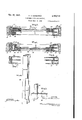
- Figure 1 is a face view of storm sash constructed in accordance with the present specification, shown installed in a typical window frame, the view being partly broken away;
- Figure 2 is a vertical section on the line 2-2 of Figure 1;
- Figure 3 is a fragmentary vertical section on the line 3-3 of Figure 1;
- Figure 4 is a fragmentary vertical section on the line 2-4 of Figure 1;
- Figure 5 is a horizontal section on the line 5-5 of Figure 1;
- Figure 6 is a horizontal of Figure 1;
- Figure 7 is a fragmentary horizontal section on the line 1-1 of Figure 1;
- Figure 8 is a fragmentary horizontal section on the line 8-8 of Figure 1;
- Figure 9 is a perspective view of one of the side members of the permanent holding frame.
- Figure 10 is a perspective view of one of the corner members of the storm sash proper.
- the permanent holding frame consists of four members: two vertical side members 20 and 28,
- Side members 20 and 2i are E-shaped channel bars whose outer parallel walls are cut out in part, one at its upper portion, the other at its lower portion. The purposeof these cut out portions will be disclosed shortly.
- Top member 22 in cross section appears as shown in Figur 3. It has three parallel walls; a wide outer wall 24, a medium inner wall 25, and
- outer wall 25 which are joined at right angles to the top wall or ceiling 21, said parallel walls being spaced apart the same distance as the parallel walls of the E-shaped channel bars 22 and 21.
- Outer wall 24 and inner wall 25 are joined at a point where the latter terminates by means of a downwardly humped web .28.
- the hump 29 of said web constitutes the upper bead member of the holding frame.
- Bottom frame member 23 is a hollow member made, preferably, of a single piece of sheet material bent backward upon itself. It has no bottom plate to correspond to the top plate 27 of the top cross member 22. It has three parallel walls 30, 3i and 32 of which outer walls 30 and 32 register at the bottom, outer wall 30 is joined at the top to the bottom of inner wall 3
- a plurality of riveted spacers 35 assist in properly spacing walls 3! and 32. Walls 3! and 32 are spaced to fit into the space between adjacentparallel walls of the E-shaped channel bars I and walls 30 and 32 are spaced to fit into the space between the outer parallel walls of said channel bars.
- the four members constituting the holding frame may be made of sheet metal or of any other suitable material. They may be pressed into shape or they may be made in any other desirable way. They may be fabricated in different standard sizes or they may be cut to size on the job.
- top member 22 When installed, top member 22 is aiiixed, as by screws, to the top iii of the window frame, and side members 20 and 2i are aifixed in the same manner to the side posts ll of the window frame.
- may also be affixed to the top member 22 by means of screws 22a and the bottom member 23 may be afiixed to the side members by means of screw 23a.
- Bottom member 23 is not afixed to the sill I9 of the window frame.
- is affixed, as by rivets, a U-shaped channel member 32 to whose web is amxed, as by screws, a bead 43.
- slidably disposed in each of the U- shaped channels 44 and 45 formed by the walls of E-shaped side member 20 is a U-shaped member 48, similar, in all substantial respects, to U- shaped members 42.
- Torsion springs 41 tend to push members 46 out of their respective channels and cross bars 48 which are aflixed to the side member 20 and pass through apertures in the side walls of said members 46, prevent said members 46 from leaving their respective channels.
- Beads 49 are aflixed, as by screws, to the webs of U-shaped member 46.
- the sash proper comprises side frame members 50 and 51, a top member 52, a bottom member 53 and four corner members 54.
- Members 50, 52 and 53 are elongated channel bars which are H-shapecl in cross section, the ends of the inner legs thereof, being bent inwardly to form a pair of flanges 55. These flanges hold, in the space that separates them, pane of glass 56.
- the lower sash frame has an inwardly extending flange 58 on its bottom member 53 and an outwardly extending flange 59 on its top member 52.
- the flange 59 assists in rendering the space between the frame of the upper sash and the frame of the lower sash weathertight.
- the flange 58 is a finger grip for convenience in raising or lowering the lower sash.
- the corner members 54 comprises an L- shaped element 60 which is U-shaped in cross section. This element corresponds cross sectionally to cushion 51 and by the same token, to the U-shaped channel formed by the inner legs, web and flanges'of the members 50, 5!, 52 and 53, when a pane of glass projects into said channel through the space between said flanges.
- a plate 61 is affixed to each side of said L-shaped element, in the manner shown in Figure 10. Said plate corresponds in width to members 50, 5
- the cushions 51, L- shaped elements 60 and pane of glass are inserted into members 50, 5
- the sash is insertedinto the vertical channels formed by the parallel walls of the E-shaped side members 20 and 2!. This is done through the cut-outportions in said side members. It will be seen in Figures 5 and 6 that the outer legs of H-shaped side members 59 and Si straddle beads 43 and 49. It will be seen in Figures 3 and 4 that the outer legs of top and bottom members 52 and 53 of the sash straddle, respectively, beads 29 and 34. Plates 6! of the corner members of the sash frame also straddle the beads.
- U-shaped members 46 are brought into frictional contact with the sash frame. This permits of raising or lowering either sash to any height and leaving it there, This close contact also makes for weathertight construction. Weathertight construction is also provided by the pressure contact of the member 39 with the window sill, previously described.
- Screens may be substituted for the storm sash when provided with frames which correspond to the sash frames above described.
- a sash frame for window sash, raid sash having rectangular guide channels on top, bottom and sides, said frame comprising a pair of side members aflixed to top and bottom members, said side members being E-shaped in cross section and having bead carrying guide members which are U-shaped in cross section in each of their channels, the U-shaped guide members in one of said E-shaped side members being urged outwardly against the window sash by means of tension elements, said top member being substantially E-shaped in cross section, the outer leg of the E being longer than the middle leg and the latter being longer than the inner leg thereof, a bead being formed at the end of the middle leg, between said middle leg and said outer leg, said bottom member comprising a pair of hollow telescoping members, a plurality of tension elements disposed between said telescoping members and urging them into extended position, the upper telescoping member having a bead formed at the top thereof, the lower of said members having a short inner leg and a long outer leg to conform to the downward slope of
- a sash frame for window sash said sash having rectangular guide channels, a top member which is substantially E-shaped in cross section, the outer leg of the E being longer than the middle leg and the latter being longer than the inner leg thereof, a bead being formed at the end of the middle leg, between said middle leg and said. outer leg, said bead being adapted to engage the corresponding rectangular channels of the window sash.
- a sash frame for window sash said sash having rectangular guide channels, a bottom member comprising a pair of hollow telescoping members, a plurality of tension elements disposed between said members and urging them into extended position, the upper telescoping member having a bead formed at the top thereof, the lower of said members having a short inner leg and a long outer leg to conform to the downward slope of a window sill. said bead being adapted to engage the corresponding rectangular guide channels of the window sash.
Description
NW. N, 14?. H. A. KAMMERER REMOVABLE SASH CONSTRUCTION s Sheets-Sheet 1 Filed Sept. 2, 1944 Harry JZJCan-nrn erer ATTORNEYS s snets-sheet 2 INVEN TOR.
ATvoRmzvs w ffarry/ifl-Kammerer H. A. KAMMERER Filed Sept. 2, 1944 REMOVABLE SASH CONSTRUCTION Nov. 11, 11941-7.
NW, m, 1%? h H, A. KAMMERE R mgwm REMOVABLE SASH CONSTRUCTION Filed Sept. 2, 19% 3 Sheets-Sheet 3 ATTORNEYS Patented Nov. 11,194?
UNITED STATES PATENT CFFICE REMOVABLE SASH CONSTRUCTION Harry A. Kammerer, Mount Vernon, N. Y. Application September 2, 1944, Serial No. 552,486 3 Claims. (Cl. 189-72) A further object is the provision of storm sash which may be slidably opened and closed in the same manner as windows of standard construction.
A still further object is the provision of storm sash which i fractionally engaged by its permanent holding means to hold it in any desired position, open or closed.
Still another object is the provision of storm sash which may be opened to register with the open window for the purpose of providing better ventilation.
These and other objects are attained by struc ture and mechanism illustrated in the accompanying drawing in which Figure 1 is a face view of storm sash constructed in accordance with the present specification, shown installed in a typical window frame, the view being partly broken away;
Figure 2 is a vertical section on the line 2-2 of Figure 1;
Figure 3 is a fragmentary vertical section on the line 3-3 of Figure 1;
Figure 4 is a fragmentary vertical section on the line 2-4 of Figure 1;
Figure 5 is a horizontal section on the line 5-5 of Figure 1;
Figure 6 is a horizontal of Figure 1;
Figure 7 is a fragmentary horizontal section on the line 1-1 of Figure 1;
Figure 8 is a fragmentary horizontal section on the line 8-8 of Figure 1;
Figure 9 is a perspective view of one of the side members of the permanent holding frame; and
Figure 10 is a perspective view of one of the corner members of the storm sash proper.
The permanent holding frame consists of four members: two vertical side members 20 and 28,
section on the line E$ one top cross member 22 and one bottom cross member 23.
a. narrow outer wall 25 which are joined at right angles to the top wall or ceiling 21, said parallel walls being spaced apart the same distance as the parallel walls of the E-shaped channel bars 22 and 21. Outer wall 24 and inner wall 25 are joined at a point where the latter terminates by means of a downwardly humped web .28. The hump 29 of said web constitutes the upper bead member of the holding frame.
Slidably disposed in said bottom frame member 23 is a smaller, somewhat similarly shaped member 36. A plurality of torsion springs 3? disposed between the web of frame member 23 and the corresponding web of member 36 tend to urge member 36 downwardly against window sill IS. The purpose of this arrangement will shortly become apparent. Slots 38 in member 36 accommodate spacers 35.
The four members constituting the holding frame may be made of sheet metal or of any other suitable material. They may be pressed into shape or they may be made in any other desirable way. They may be fabricated in different standard sizes or they may be cut to size on the job.
When installed, top member 22 is aiiixed, as by screws, to the top iii of the window frame, and side members 20 and 2i are aifixed in the same manner to the side posts ll of the window frame. The side members 20 and 2| may also be affixed to the top member 22 by means of screws 22a and the bottom member 23 may be afiixed to the side members by means of screw 23a.- Bottom member 23 is not afixed to the sill I9 of the window frame.
It will be noted that in each of the U shaped channels 40 and ll formed by the walls of E- shaped side member 2| is affixed, as by rivets, a U-shaped channel member 32 to whose web is amxed, as by screws, a bead 43. It will also be noted that slidably disposed in each of the U- shaped channels 44 and 45 formed by the walls of E-shaped side member 20 is a U-shaped member 48, similar, in all substantial respects, to U- shaped members 42. Torsion springs 41 tend to push members 46 out of their respective channels and cross bars 48 which are aflixed to the side member 20 and pass through apertures in the side walls of said members 46, prevent said members 46 from leaving their respective channels. Beads 49 are aflixed, as by screws, to the webs of U-shaped member 46.
The sash proper comprises side frame members 50 and 51, a top member 52, a bottom member 53 and four corner members 54. Members 50, 52 and 53 are elongated channel bars which are H-shapecl in cross section, the ends of the inner legs thereof, being bent inwardly to form a pair of flanges 55. These flanges hold, in the space that separates them, pane of glass 56. A cushion or insulating material 51', such as rubber or felt, is carried by these members 50, 5|, 52 and 53 in the space formed by the web portionsthereof, the inner leg portions and the flanges. This cushion may be made in U- shaped cross section to accommodate the edge of the glass pane. This is shown in Figures 3 and 4, for example.
It will be seen in Figure 2 that the lower sash frame has an inwardly extending flange 58 on its bottom member 53 and an outwardly extending flange 59 on its top member 52. The flange 59 assists in rendering the space between the frame of the upper sash and the frame of the lower sash weathertight. The flange 58 is a finger grip for convenience in raising or lowering the lower sash.
The corner members 54 comprises an L- shaped element 60 which is U-shaped in cross section. This element corresponds cross sectionally to cushion 51 and by the same token, to the U-shaped channel formed by the inner legs, web and flanges'of the members 50, 5!, 52 and 53, when a pane of glass projects into said channel through the space between said flanges. A plate 61 is affixed to each side of said L-shaped element, in the manner shown in Figure 10. Said plate corresponds in width to members 50, 5|, 52 and 53.
To assemble the sash, the cushions 51, L- shaped elements 60 and pane of glass are inserted into members 50, 5|, 52 and 53 in the manner indicated. Said members and the L- shaped elements are then fixed together as by means of screws.
To install the sash into the holding frame, the sash is insertedinto the vertical channels formed by the parallel walls of the E-shaped side members 20 and 2!. This is done through the cut-outportions in said side members. It will be seen in Figures 5 and 6 that the outer legs of H-shaped side members 59 and Si straddle beads 43 and 49. It will be seen in Figures 3 and 4 that the outer legs of top and bottom members 52 and 53 of the sash straddle, respectively, beads 29 and 34. Plates 6! of the corner members of the sash frame also straddle the beads.
Screens may be substituted for the storm sash when provided with frames which correspond to the sash frames above described.
Modifications of the invention may be incorporated therein without departing from the broad principles thereof.
I claim:
1. A sash frame for window sash, raid sash having rectangular guide channels on top, bottom and sides, said frame comprising a pair of side members aflixed to top and bottom members, said side members being E-shaped in cross section and having bead carrying guide members which are U-shaped in cross section in each of their channels, the U-shaped guide members in one of said E-shaped side members being urged outwardly against the window sash by means of tension elements, said top member being substantially E-shaped in cross section, the outer leg of the E being longer than the middle leg and the latter being longer than the inner leg thereof, a bead being formed at the end of the middle leg, between said middle leg and said outer leg, said bottom member comprising a pair of hollow telescoping members, a plurality of tension elements disposed between said telescoping members and urging them into extended position, the upper telescoping member having a bead formed at the top thereof, the lower of said members having a short inner leg and a long outer leg to conform to the downward slope of a window sill, the beads in said top, bottom and side frame members being adapted, respectively, to engage the top, bottom and side guide channels of the window sash.
2. In a sash frame for window sash, said sash having rectangular guide channels, a top member which is substantially E-shaped in cross section, the outer leg of the E being longer than the middle leg and the latter being longer than the inner leg thereof, a bead being formed at the end of the middle leg, between said middle leg and said. outer leg, said bead being adapted to engage the corresponding rectangular channels of the window sash.
3. In a sash frame for window sash, said sash having rectangular guide channels, a bottom member comprising a pair of hollow telescoping members, a plurality of tension elements disposed between said members and urging them into extended position, the upper telescoping member having a bead formed at the top thereof, the lower of said members having a short inner leg and a long outer leg to conform to the downward slope of a window sill. said bead being adapted to engage the corresponding rectangular guide channels of the window sash.
HARRY A. KAMMERER.
REFERENCES CITED The following references are of record in the file of this patent:
UNITED STATES PATENTS Number Name Date 1,022,719 Brown Apr. 9, 1912 1,063,346 Forsyth June 3, 1913 1,506,960 Watson Sept. 2, 1924 1,765,442 Paitl June 24, 1930 1,908,270 Shaffer -1 May 9, 1933 1,998,315 Glaser Apr. 16, 1935 2,156,964 Biddle May 2, 1939 2,177,463 Schunk Oct. 24, 1939 2,288,558 Vose June 30, 1942 2,303,129 Kurtz Nov. 24, 1942
Priority Applications (1)
| Application Number | Priority Date | Filing Date | Title |
|---|---|---|---|
| US552486A US2430772A (en) | 1944-09-02 | 1944-09-02 | Removable sash construction |
Applications Claiming Priority (1)
| Application Number | Priority Date | Filing Date | Title |
|---|---|---|---|
| US552486A US2430772A (en) | 1944-09-02 | 1944-09-02 | Removable sash construction |
Publications (1)
| Publication Number | Publication Date |
|---|---|
| US2430772A true US2430772A (en) | 1947-11-11 |
Family
ID=24205542
Family Applications (1)
| Application Number | Title | Priority Date | Filing Date |
|---|---|---|---|
| US552486A Expired - Lifetime US2430772A (en) | 1944-09-02 | 1944-09-02 | Removable sash construction |
Country Status (1)
| Country | Link |
|---|---|
| US (1) | US2430772A (en) |
Cited By (24)
| Publication number | Priority date | Publication date | Assignee | Title |
|---|---|---|---|---|
| US2523070A (en) * | 1947-07-08 | 1950-09-19 | Theodore L Smalley | Adjustable sill block |
| US2541948A (en) * | 1948-04-26 | 1951-02-13 | Ace Storm Window Company | Single sash storm window mounting |
| US2564264A (en) * | 1947-02-12 | 1951-08-14 | Wisco Inc | Window |
| US2585471A (en) * | 1947-05-10 | 1952-02-12 | Harry J Kammerer | Window structure |
| US2589685A (en) * | 1946-04-02 | 1952-03-18 | Jr Alfred B Edwards | Window |
| US2605870A (en) * | 1946-11-27 | 1952-08-05 | Weather Proof Co | Window construction |
| US2607964A (en) * | 1948-03-11 | 1952-08-26 | Ventsulator Mfg Co Inc | Double sash metal frame window |
| US2612660A (en) * | 1950-05-15 | 1952-10-07 | Stephen M Casey | Window construction |
| US2629143A (en) * | 1949-04-06 | 1953-02-24 | Tilt Type Products Inc | Storm window |
| US2630891A (en) * | 1947-02-13 | 1953-03-10 | Zitomer Abe | Window structure |
| US2640535A (en) * | 1950-06-29 | 1953-06-02 | Eagle Picher Co | Triple sliding storm window unit |
| US2643422A (en) * | 1947-10-04 | 1953-06-30 | Prosper L Gottschalk | Window construction |
| US2664599A (en) * | 1948-01-02 | 1954-01-05 | Alumatic Corp Of America | Window structure |
| US2677861A (en) * | 1952-06-30 | 1954-05-11 | Leo H Weiss | Weather stripping for windows having vertically slidable sashes |
| US2678479A (en) * | 1949-05-19 | 1954-05-18 | Jr Alfred B Edwards | Window construction |
| US2685110A (en) * | 1950-04-01 | 1954-08-03 | Gen Bronze Corp | Sliding window construction |
| US2704573A (en) * | 1955-03-22 | russell | ||
| US2740998A (en) * | 1952-08-11 | 1956-04-10 | Alumatic Corp Of America | Window structures |
| US2742118A (en) * | 1950-12-23 | 1956-04-17 | Sylvan Joseph | Window assembly |
| US2774997A (en) * | 1951-08-02 | 1956-12-25 | Alumatic Corp Of America | Sash and sash frames |
| US2781090A (en) * | 1954-10-15 | 1957-02-12 | Wisconsin Window Unit Co | Combination screen and storm sash frames |
| US2846734A (en) * | 1948-01-02 | 1958-08-12 | Zitomer Abe | Window structures |
| US3054152A (en) * | 1958-07-23 | 1962-09-18 | Jr Earl M Trammell | Window unit |
| US3256641A (en) * | 1962-12-20 | 1966-06-21 | Malta Mfg Company | Window units |
Citations (10)
| Publication number | Priority date | Publication date | Assignee | Title |
|---|---|---|---|---|
| US1022719A (en) * | 1911-11-06 | 1912-04-09 | Stewart Brown | Wind-shield frame. |
| US1063346A (en) * | 1907-08-12 | 1913-06-03 | George H Forsyth | Window construction. |
| US1506960A (en) * | 1922-07-21 | 1924-09-02 | William H Watson | Unitary screen and closure arrangement for window openings |
| US1765442A (en) * | 1929-06-10 | 1930-06-24 | Michael J Paitl | Window construction |
| US1908270A (en) * | 1930-12-12 | 1933-05-09 | Om Edwards Co Inc | Window sash construction |
| US1998315A (en) * | 1933-12-16 | 1935-04-16 | Chamberlin Metal Weather Strip | Storm sash and frame |
| US2156964A (en) * | 1936-08-19 | 1939-05-02 | Oscar H Biddle | Insulating sash |
| US2177463A (en) * | 1938-06-30 | 1939-10-24 | Nat Lock Washer Co | Car or bus window construction |
| US2288558A (en) * | 1939-11-28 | 1942-06-30 | Mathews Brother Co | Friction window sash mounting |
| US2303129A (en) * | 1939-12-30 | 1942-11-24 | Libbey Owens Ford Glass Co | Window construction |
-
1944
- 1944-09-02 US US552486A patent/US2430772A/en not_active Expired - Lifetime
Patent Citations (10)
| Publication number | Priority date | Publication date | Assignee | Title |
|---|---|---|---|---|
| US1063346A (en) * | 1907-08-12 | 1913-06-03 | George H Forsyth | Window construction. |
| US1022719A (en) * | 1911-11-06 | 1912-04-09 | Stewart Brown | Wind-shield frame. |
| US1506960A (en) * | 1922-07-21 | 1924-09-02 | William H Watson | Unitary screen and closure arrangement for window openings |
| US1765442A (en) * | 1929-06-10 | 1930-06-24 | Michael J Paitl | Window construction |
| US1908270A (en) * | 1930-12-12 | 1933-05-09 | Om Edwards Co Inc | Window sash construction |
| US1998315A (en) * | 1933-12-16 | 1935-04-16 | Chamberlin Metal Weather Strip | Storm sash and frame |
| US2156964A (en) * | 1936-08-19 | 1939-05-02 | Oscar H Biddle | Insulating sash |
| US2177463A (en) * | 1938-06-30 | 1939-10-24 | Nat Lock Washer Co | Car or bus window construction |
| US2288558A (en) * | 1939-11-28 | 1942-06-30 | Mathews Brother Co | Friction window sash mounting |
| US2303129A (en) * | 1939-12-30 | 1942-11-24 | Libbey Owens Ford Glass Co | Window construction |
Cited By (24)
| Publication number | Priority date | Publication date | Assignee | Title |
|---|---|---|---|---|
| US2704573A (en) * | 1955-03-22 | russell | ||
| US2589685A (en) * | 1946-04-02 | 1952-03-18 | Jr Alfred B Edwards | Window |
| US2605870A (en) * | 1946-11-27 | 1952-08-05 | Weather Proof Co | Window construction |
| US2564264A (en) * | 1947-02-12 | 1951-08-14 | Wisco Inc | Window |
| US2630891A (en) * | 1947-02-13 | 1953-03-10 | Zitomer Abe | Window structure |
| US2585471A (en) * | 1947-05-10 | 1952-02-12 | Harry J Kammerer | Window structure |
| US2523070A (en) * | 1947-07-08 | 1950-09-19 | Theodore L Smalley | Adjustable sill block |
| US2643422A (en) * | 1947-10-04 | 1953-06-30 | Prosper L Gottschalk | Window construction |
| US2846734A (en) * | 1948-01-02 | 1958-08-12 | Zitomer Abe | Window structures |
| US2664599A (en) * | 1948-01-02 | 1954-01-05 | Alumatic Corp Of America | Window structure |
| US2607964A (en) * | 1948-03-11 | 1952-08-26 | Ventsulator Mfg Co Inc | Double sash metal frame window |
| US2541948A (en) * | 1948-04-26 | 1951-02-13 | Ace Storm Window Company | Single sash storm window mounting |
| US2629143A (en) * | 1949-04-06 | 1953-02-24 | Tilt Type Products Inc | Storm window |
| US2678479A (en) * | 1949-05-19 | 1954-05-18 | Jr Alfred B Edwards | Window construction |
| US2685110A (en) * | 1950-04-01 | 1954-08-03 | Gen Bronze Corp | Sliding window construction |
| US2612660A (en) * | 1950-05-15 | 1952-10-07 | Stephen M Casey | Window construction |
| US2640535A (en) * | 1950-06-29 | 1953-06-02 | Eagle Picher Co | Triple sliding storm window unit |
| US2742118A (en) * | 1950-12-23 | 1956-04-17 | Sylvan Joseph | Window assembly |
| US2774997A (en) * | 1951-08-02 | 1956-12-25 | Alumatic Corp Of America | Sash and sash frames |
| US2677861A (en) * | 1952-06-30 | 1954-05-11 | Leo H Weiss | Weather stripping for windows having vertically slidable sashes |
| US2740998A (en) * | 1952-08-11 | 1956-04-10 | Alumatic Corp Of America | Window structures |
| US2781090A (en) * | 1954-10-15 | 1957-02-12 | Wisconsin Window Unit Co | Combination screen and storm sash frames |
| US3054152A (en) * | 1958-07-23 | 1962-09-18 | Jr Earl M Trammell | Window unit |
| US3256641A (en) * | 1962-12-20 | 1966-06-21 | Malta Mfg Company | Window units |
Similar Documents
| Publication | Publication Date | Title |
|---|---|---|
| US2430772A (en) | Removable sash construction | |
| US2916112A (en) | Metal window construction | |
| US3256641A (en) | Window units | |
| US1954017A (en) | Ventilator panel for windows | |
| GB972167A (en) | Louver structure | |
| US2530708A (en) | Building unit | |
| US2342614A (en) | Guide frame for storm window, window screen, or like inserts | |
| US2895182A (en) | Window structure | |
| US4020595A (en) | Door of adjustable height | |
| US2630891A (en) | Window structure | |
| US1948108A (en) | Weather strip | |
| US2329485A (en) | Supplemental metallic window unit | |
| US1636593A (en) | John edwin dennis | |
| US3172169A (en) | Retaining structure for window sash and counterweights | |
| US1740960A (en) | Window-screen fixture | |
| US2651082A (en) | Window structure | |
| US2589938A (en) | Garage door | |
| US2587440A (en) | Storm blind | |
| US1882951A (en) | Rolling screen | |
| US2608278A (en) | Window construction | |
| US2583851A (en) | Convertible window | |
| US1730471A (en) | Window construction | |
| US1666839A (en) | Metallic window sash | |
| US2619690A (en) | Window or other slidable closure | |
| US2326897A (en) | Metal sash structure |